Quick Start GuideMELSEC iQ-R Series Simple Motion Module
Let's Start!
Applicable Model
-RD77MS2
-RD77MS4
-RD77MS8
-RD77MS16
Mitsubishi Servo System ControllersQuick Start Guide
FACTORY AUTOMATION

1
RD77MS Quick Start Guide
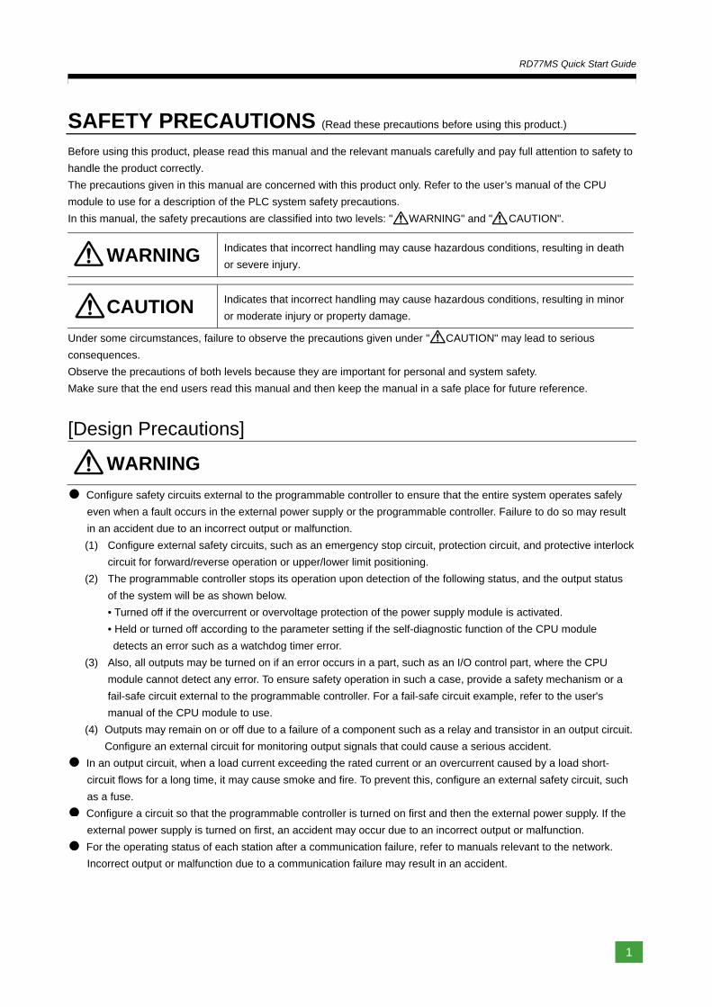
SAFETY PRECAUTIONS (Read these precautions before using this product.)
Before using this product, please read this manual and the relevant manuals carefully and pay full attention to safety to
handle the product correctly.
The precautions given in this manual are concerned with this product only. Refer to the user’s manual of the CPU
module to use for a description of the PLC system safety precautions.
In this manual, the safety precautions are classified into two levels: " WARNING" and " CAUTION".
WARNING Indicates that incorrect handling may cause hazardous conditions, resulting in death
or severe injury.
CAUTION Indicates that incorrect handling may cause hazardous conditions, resulting in minor
or moderate injury or property damage.
Under some circumstances, failure to observe the precautions given under " CAUTION" may lead to serious
consequences.
Observe the precautions of both levels because they are important for personal and system safety.
Make sure that the end users read this manual and then keep the manual in a safe place for future reference.
[Design Precautions]
WARNING
Configure safety circuits external to the programmable controller to ensure that the entire system operates safely
even when a fault occurs in the external power supply or the programmable controller. Failure to do so may result
in an accident due to an incorrect output or malfunction.
(1) Configure external safety circuits, such as an emergency stop circuit, protection circuit, and protective interlock
circuit for forward/reverse operation or upper/lower limit positioning.
(2) The programmable controller stops its operation upon detection of the following status, and the output status
of the system will be as shown below.
• Turned off if the overcurrent or overvoltage protection of the power supply module is activated.
• Held or turned off according to the parameter setting if the self-diagnostic function of the CPU module
detects an error such as a watchdog timer error.
(3) Also, all outputs may be turned on if an error occurs in a part, such as an I/O control part, where the CPU
module cannot detect any error. To ensure safety operation in such a case, provide a safety mechanism or a
fail-safe circuit external to the programmable controller. For a fail-safe circuit example, refer to the user's
manual of the CPU module to use.
(4) Outputs may remain on or off due to a failure of a component such as a relay and transistor in an output circuit.
Configure an external circuit for monitoring output signals that could cause a serious accident.
In an output circuit, when a load current exceeding the rated current or an overcurrent caused by a load short-
circuit flows for a long time, it may cause smoke and fire. To prevent this, configure an external safety circuit, such
as a fuse.
Configure a circuit so that the programmable controller is turned on first and then the external power supply. If the
external power supply is turned on first, an accident may occur due to an incorrect output or malfunction.
For the operating status of each station after a communication failure, refer to manuals relevant to the network.
Incorrect output or malfunction due to a communication failure may result in an accident.
要
2
RD77MS Quick Start Guide
WARNING
When connecting an external device with a CPU module or intelligent function module to modify data of a running
programmable controller, configure an interlock circuit in the program to ensure that the entire system will always
operate safely. For other forms of control (such as program modification, parameter change, forced output, or
operating status change) of a running programmable controller, read the relevant manuals carefully and ensure
that the operation is safe before proceeding. Improper operation may damage machines or cause accidents.
Especially, when a remote programmable controller is controlled by an external device, immediate action cannot
be taken if a problem occurs in the programmable controller due to a communication failure. To prevent this,
configure an interlock circuit in the program, and determine corrective actions to be taken between the external
device and CPU module in case of a communication failure.
Do not write any data to the "system area" and "write-protect area" of the buffer memory in the module. Also, do
not use any "use prohibited" signals as an output signal from the CPU module to each module. Doing so may
cause malfunction of the programmable controller system. For the "system area", "write-protect area", and the
"use prohibited" signals, refer to the user's manual for the module used.
If a communication cable is disconnected, the network may be unstable, resulting in a communication failure of
multiple stations. Configure an interlock circuit in the program to ensure that the entire system will always operate
safely even if communications fail. Failure to do so may result in an accident due to an incorrect output or
malfunction.
To maintain the safety of the programmable controller system against unauthorized access from external devices
via the network, take appropriate measures. To maintain the safety against unauthorized access via the Internet,
take measures such as installing a firewall.
Configure safety circuits external to the programmable controller to ensure that the entire system operates safely
even when a fault occurs in the external power supply or the programmable controller. Failure to do so may result
in an accident due to an incorrect output or malfunction.
(1) Machine home position return is controlled by two kinds of data: a home position return direction and a home
position return speed. Deceleration starts when the near-point dog signal turns on. If an incorrect home
position return direction is set, motion control may continue without deceleration. To prevent machine damage
caused by this, configure an interlock circuit external to the programmable controller.
(2) When the module detects an error, the motion slows down and stops or the motion suddenly stops, depending
on the stop group setting in parameter. Set the parameter to meet the specifications of a positioning control
system. In addition, set the home position return parameter and positioning data within the specified setting
range.
(3) Outputs may remain on or off, or become undefined due to a failure of a component such as an insulation
element and transistor in an output circuit, where the module cannot detect any error. In a system that the
incorrect output could cause a serious accident, configure an external circuit for monitoring output signals.
If safety standards (ex., robot safety rules, etc.,) apply to the system using the module, servo amplifier and
servomotor, make sure that the safety standards are satisfied.
Construct a safety circuit externally of the module or servo amplifier if the abnormal operation of the module or
servo amplifier differs from the safety directive operation in the system.
Do not remove the SSCNETIII cable while turning on the control circuit power supply of Multiple CPU system and
servo amplifier. Do not see directly the light generated from SSCNETIII connector of the module or servo
amplifier and the end of SSCNETIII cable. When the light gets into eyes, you may feel something wrong with
eyes. (The light source of SSCNETIII complies with class1 defined in JISC6802 or IEC60825-1.).
3
RD77MS Quick Start Guide
[Design Precautions]
CAUTION
Do not install the control lines or communication cables together with the main circuit lines or power cables. Keep
a distance of 100 mm or more between them. Failure to do so may result in malfunction due to noise.
During control of an inductive load such as a lamp, heater, or solenoid valve, a large current (approximately ten
times greater than normal) may flow when the output is turned from off to on. Therefore, use a module that has a
sufficient current rating.
After the CPU module is powered on or is reset, the time taken to enter the RUN status varies depending on the
system configuration, parameter settings, and/or program size. Design circuits so that the entire system will
always operate safely, regardless of the time.
Do not power off the programmable controller or do not reset the CPU module during the setting registration.
Doing so will make the data in the flash ROM undefined. The data need to be set in the buffer memory and to be
written to the flash ROM again. Doing so may cause malfunction or failure of the module.
Reset the CPU module after changing the parameters. Failure to do so may cause malfunction because the
previous parameter settings remain in the module.
When changing the operating status of the CPU module from external devices (such as remote RUN/STOP),
select "Do Not Open by Program" for "Opening Method" in the module parameters. If "Open by Program" is
selected, an execution of remote STOP causes the communication line to close. Consequently, the CPU module
cannot reopen the communication line, and external devices cannot execute the remote RUN.
[Installation Precautions]
WARNING
Shut off the external power supply (all phases) used in the system before mounting or removing the module.
Failure to do so may result in electric shock or cause the module to fail or malfunction.
要
4
RD77MS Quick Start Guide
[Installation Precautions]
CAUTION
Use the programmable controller in an environment that meets the general specifications in the manual "Safety
Guidelines" included in the base unit. Failure to do so may result in electric shock, fire, malfunction, or damage to
or deterioration of the product.
To mount a module, place the concave part(s) located at the bottom onto the guide(s) of the base unit, and push
in the module until the hook(s) located at the top snaps into place. Incorrect mounting may cause malfunction,
failure, or drop of the module.
When using the programmable controller in an environment of frequent vibrations, fix the module with a screw.
Tighten the screws within the specified torque range. Undertightening can cause drop of the screw, short circuit,
or malfunction. Overtightening can damage the screw and/or module, resulting in drop, short circuit, or
malfunction.
When using an extension cable, connect it to the extension cable connector of the base unit securely. Check the
connection for looseness. Poor contact may cause incorrect input or output.
When using an SD memory card, fully insert it into the memory card slot. Check that it is inserted completely.
Poor contact may cause malfunction.
Securely insert an extended SRAM cassette into the cassette connector of a CPU module. After insertion, close
the cassette cover and check that the cassette is inserted completely. Poor contact may cause malfunction.
Do not directly touch any conductive parts and electronic components of the module, SD memory card, extended
SRAM cassette, or connector. Doing so may cause malfunction or failure of the module.
[Wiring Precautions]
WARNING
Shut off the external power supply (all phases) used in the system before installation and wiring. Failure to do so
may result in electric shock or damage to the product.
After installation and wiring, attach the included terminal cover to the module before turning it on for operation.
Failure to do so may result in electric shock.
5
RD77MS Quick Start Guide
[Wiring Precautions]
CAUTION
Individually ground the FG and LG terminals of the programmable controller with a ground resistance of 100 ohm
or less. Failure to do so may result in electric shock or malfunction.
Use applicable solderless terminals and tighten them within the specified torque range. If any spade solderless
terminal is used, it may be disconnected when the terminal screw comes loose, resulting in failure.
Check the rated voltage and signal layout before wiring to the module, and connect the cables correctly.
Connecting a power supply with a different voltage rating or incorrect wiring may cause fire or failure.
Connectors for external devices or coaxial cables must be crimped or pressed with the tool specified by the
manufacturer, or must be correctly soldered. Incomplete connections may cause short circuit, fire, or malfunction.
Securely connect the connector to the module. Poor contact may cause malfunction.
Do not install the control lines or communication cables together with the main circuit lines or power cables. Keep
a distance of 100 mm or more between them. Failure to do so may result in malfunction due to noise.
Place the cables in a duct or clamp them. If not, dangling cable may swing or inadvertently be pulled, resulting in
damage to the module or cables or malfunction due to poor contact. Do not clamp the extension cables with the
jacket stripped.
Check the interface type and correctly connect the cable. Incorrect wiring (connecting the cable to an incorrect
interface) may cause failure of the module and external device.
Tighten the terminal screws or connector screws within the specified torque range. Undertightening can cause
drop of the screw, short circuit, fire, or malfunction. Overtightening can damage the screw and/or module,
resulting in drop, short circuit, fire, or malfunction.
When disconnecting the cable from the module, do not pull the cable by the cable part. For the cable with
connector, hold the connector part of the cable. For the cable connected to the terminal block, loosen the terminal
screw. Pulling the cable connected to the module may result in malfunction or damage to the module or cable.
Prevent foreign matter such as dust or wire chips from entering the module. Such foreign matter can cause a fire,
failure, or malfunction.
A protective film is attached to the top of the module to prevent foreign matter, such as wire chips, from entering
the module during wiring. Do not remove the film during wiring. Remove it for heat dissipation before system
operation.
Mitsubishi programmable controllers must be installed in control panels. Connect the main power supply to the
power supply module in the control panel through a relay terminal block. Wiring and replacement of a power
supply module must be performed by qualified maintenance personnel with knowledge of protection against
electric shock. For wiring, refer to the MELSEC iQ-R Module Configuration Manual.
For Ethernet cables to be used in the system, select the ones that meet the specifications in the MELSEC iQ-R
Ethernet/CC-Link IE User's Manual (Startup). If not, normal data transmission is not guaranteed.
要
6
RD77MS Quick Start Guide
[Startup and Maintenance Precautions]
WARNING
Do not touch any terminal while power is on. Doing so will cause electric shock or malfunction.
Correctly connect the battery connector. Do not charge, disassemble, heat, short-circuit, solder, or throw the
battery into the fire. Also, do not expose it to liquid or strong shock. Doing so may cause the battery to generate
heat, explode, ignite, or leak, resulting in injury or fire.
Shut off the external power supply (all phases) used in the system before cleaning the module or retightening the
terminal screws, connector screws, or module fixing screws. Failure to do so may result in electric shock or cause
the module to fail or malfunction.
[Startup and Maintenance Precautions]
CAUTION
When connecting an external device with a CPU module or intelligent function module to modify data of a running
programmable controller, configure an interlock circuit in the program to ensure that the entire system will always
operate safely. For other forms of control (such as program modification, parameter change, forced output, or
operating status change) of a running programmable controller, read the relevant manuals carefully and ensure
that the operation is safe before proceeding. Improper operation may damage machines or cause accidents.
Especially, when a remote programmable controller is controlled by an external device, immediate action cannot
be taken if a problem occurs in the programmable controller due to a communication failure. To prevent this,
configure an interlock circuit in the program, and determine corrective actions to be taken between the external
device and CPU module in case of a communication failure.
Do not disassemble or modify the modules. Doing so may cause failure, malfunction, injury, or a fire.
Use any radio communication device such as a cellular phone or PHS (Personal Handyphone System) more than
25 cm away in all directions from the programmable controller. Failure to do so may cause malfunction.
Shut off the external power supply (all phases) used in the system before mounting or removing the module.
Failure to do so may cause the module to fail or malfunction.
Tighten the screws within the specified torque range. Undertightening can cause drop of the component or wire,
short circuit, or malfunction. Overtightening can damage the screw and/or module, resulting in drop, short circuit,
or malfunction.
After the first use of the product, do not mount/remove the module to/from the base unit, and the terminal block
to/from the module, and do not insert/remove the extended SRAM cassette to/from the CPU module more than
50 times (IEC 61131-2 compliant) respectively. Exceeding the limit of 50 times may cause malfunction.
After the first use of the product, do not insert/remove the SD memory card to/from the CPU module more than
500 times. Exceeding the limit may cause malfunction.
Do not touch the metal terminals on the back side of the SD memory card. Doing so may cause malfunction or
failure.
Do not touch the integrated circuits on the circuit board of an extended SRAM cassette. Doing so may cause
malfunction or failure.
Do not drop or apply shock to the battery to be installed in the module. Doing so may damage the battery, causing
the battery fluid to leak inside the battery. If the battery is dropped or any shock is applied to it, dispose of it
without using.
7
RD77MS Quick Start Guide
Startup and maintenance of a control panel must be performed by qualified maintenance personnel with
knowledge of protection against electric shock. Lock the control panel so that only qualified maintenance
personnel can operate it.
Before handling the module, touch a conducting object such as a grounded metal to discharge the static
electricity from the human body. Failure to do so may cause the module to fail or malfunction.
Before testing the operation, set a low speed value for the speed limit parameter so that the operation can be
stopped immediately upon occurrence of a hazardous condition.
Confirm and adjust the program and each parameter before operation. Unpredictable movements may occur
depending on the machine.
When using the absolute position system function, on starting up, and when the module or absolute value motor
has been replaced, always perform a home position return.
Before starting the operation, confirm the brake function.
Do not perform a megger test (insulation resistance measurement) during inspection.
After maintenance and inspections are completed, confirm that the position detection of the absolute position
detection function is correct.
Lock the control panel and prevent access to those who are not certified to handle or install electric equipment.
[Operating Precautions]
CAUTION
When changing data and operating status, and modifying program of the running programmable controller from
an external device such as a personal computer connected to an intelligent function module, read relevant
manuals carefully and ensure the safety before operation. Incorrect change or modification may cause system
malfunction, damage to the machines, or accidents.
Do not power off the programmable controller or reset the CPU module while the setting values in the buffer
memory are being written to the flash ROM in the module. Doing so will make the data in the flash ROM
undefined. The values need to be set in the buffer memory and written to the flash ROM again. Doing so also can
cause malfunction or failure of the module.
Note that when the reference axis speed is specified for interpolation operation, the speed of the partner axis (2nd,
3rd, or 4th axis) may exceed the speed limit value.
Do not go near the machine during test operations or during operations such as teaching. Doing so may lead to
injuries.
[Operating Precautions]
CAUTION
When disposing of this product, treat it as industrial waste.
When disposing of batteries, separate them from other wastes according to the local regulations. For details on
battery regulations in EU member states, refer to the MELSEC iQ-R Module Configuration Manual.

要
8
RD77MS Quick Start Guide
[Transportation Precautions]
CAUTION
When transporting lithium batteries, follow the transportation regulations. For details on the regulated models,
refer to the MELSEC iQ-R Module Configuration Manual.
The halogens (such as fluorine, chlorine, bromine, and iodine), which are contained in a fumigant used for
disinfection and pest control of wood packaging materials, may cause failure of the product. Prevent the entry of
fumigant residues into the product or consider other methods (such as heat treatment) instead of fumigation. The
disinfection and pest control measures must be applied to unprocessed raw wood.
9
RD77MS Quick Start Guide
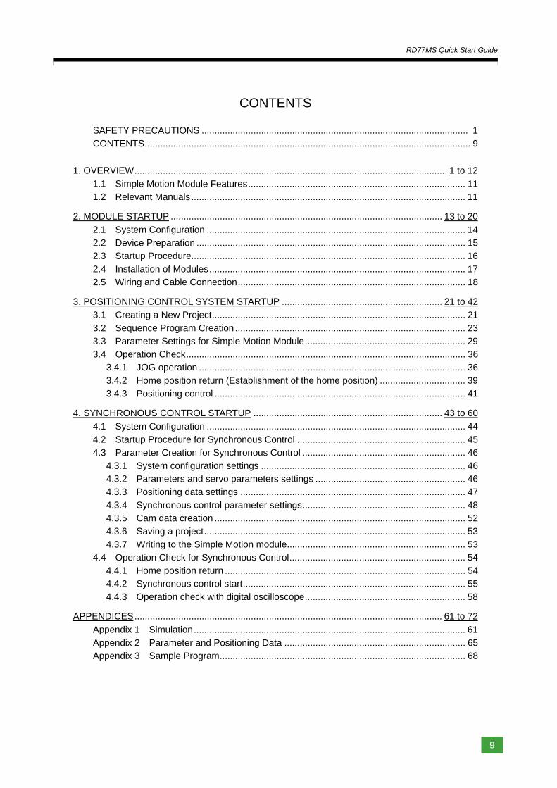
CONTENTS
SAFETY PRECAUTIONS ....................................................................................................... 1 CONTENTS .............................................................................................................................. 9
1. OVERVIEW ......................................................................................................................... 1 to 12
1.1 Simple Motion Module Features .................................................................................... 11 1.2 Relevant Manuals .......................................................................................................... 11
2. MODULE STARTUP ......................................................................................................... 13 to 20
2.1 System Configuration .................................................................................................... 14 2.2 Device Preparation ........................................................................................................ 15 2.3 Startup Procedure.......................................................................................................... 16
2.4 Installation of Modules ................................................................................................... 17 2.5 Wiring and Cable Connection ........................................................................................ 18
3. POSITIONING CONTROL SYSTEM STARTUP .............................................................. 21 to 42
3.1 Creating a New Project .................................................................................................. 21
3.2 Sequence Program Creation ......................................................................................... 23 3.3 Parameter Settings for Simple Motion Module .............................................................. 29 3.4 Operation Check ............................................................................................................ 36
3.4.1 JOG operation ....................................................................................................... 36 3.4.2 Home position return (Establishment of the home position) ................................. 39 3.4.3 Positioning control ................................................................................................. 41
4. SYNCHRONOUS CONTROL STARTUP ......................................................................... 43 to 60
4.1 System Configuration .................................................................................................... 44 4.2 Startup Procedure for Synchronous Control ................................................................. 45 4.3 Parameter Creation for Synchronous Control ............................................................... 46
4.3.1 System configuration settings ............................................................................... 46 4.3.2 Parameters and servo parameters settings .......................................................... 46 4.3.3 Positioning data settings ....................................................................................... 47
4.3.4 Synchronous control parameter settings ............................................................... 48 4.3.5 Cam data creation ................................................................................................. 52 4.3.6 Saving a project ..................................................................................................... 53
4.3.7 Writing to the Simple Motion module ..................................................................... 53 4.4 Operation Check for Synchronous Control .................................................................... 54
4.4.1 Home position return ............................................................................................. 54
4.4.2 Synchronous control start ...................................................................................... 55 4.4.3 Operation check with digital oscilloscope .............................................................. 58
APPENDICES ....................................................................................................................... 61 to 72
Appendix 1 Simulation ......................................................................................................... 61
Appendix 2 Parameter and Positioning Data ...................................................................... 65 Appendix 3 Sample Program ............................................................................................... 68

要
10
RD77MS Quick Start Guide
MEMO
1
Overview
2
Module
Startup
3
Positioning
Control S
tartup
4
Synchronous
Control S
tartup
Appendices
1. OVERVIEW
11
RD77MS Quick Start Guide
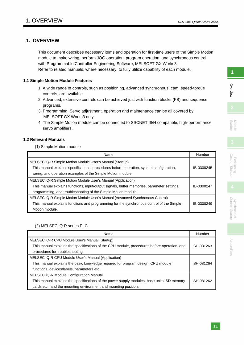
1. OVERVIEW
This document describes necessary items and operation for first-time users of the Simple Motion module to make wiring, perform JOG operation, program operation, and synchronous control
with Programmable Controller Engineering Software, MELSOFT GX Works3. Refer to related manuals, where necessary, to fully utilize capability of each module.
1.1 Simple Motion Module Features
1. A wide range of controls, such as positioning, advanced synchronous, cam, speed-torque controls, are available.
2. Advanced, extensive controls can be achieved just with function blocks (FB) and sequence programs.
3. Programming, Servo adjustment, operation and maintenance can be all covered by
MELSOFT GX Works3 only. 4. The Simple Motion module can be connected to SSCNET III/H compatible, high-performance
servo amplifiers.
1.2 Relevant Manuals
(1) Simple Motion module
(2) MELSEC iQ-R series PLC
Name Number
MELSEC iQ-R Simple Motion Module User's Manual (Startup)
This manual explains specifications, procedures before operation, system configuration,
wiring, and operation examples of the Simple Motion module.
IB-0300245
MELSEC iQ-R Simple Motion Module User's Manual (Application)
This manual explains functions, input/output signals, buffer memories, parameter settings,
programming, and troubleshooting of the Simple Motion module.
IB-0300247
MELSEC iQ-R Simple Motion Module User's Manual (Advanced Synchronous Control)
This manual explains functions and programming for the synchronous control of the Simple
Motion module.
IB-0300249
Name Number
MELSEC iQ-R CPU Module User's Manual (Startup)
This manual explains the specifications of the CPU module, procedures before operation, and
procedures for troubleshooting.
SH-081263
MELSEC iQ-R CPU Module User's Manual (Application)
This manual explains the basic knowledge required for program design, CPU module
functions, devices/labels, parameters etc.
SH-081264
MELSEC iQ-R Module Configuration Manual
This manual explains the specifications of the power supply modules, base units, SD memory
cards etc., and the mounting environment and mounting position.
SH-081262

1. OVERVIEW
12
RD77MS Quick Start Guide
(3) Servo amplifier
Name Number
MR-J4-_B_(-RJ) Servo amplifier Instruction Manual
This manual explains the I/O signals, parts names, parameters, start-up procedure and others
for MR-J4-_B(-RJ)/MR-J4-_B4(-RJ)/MR-J4-_B1(-RJ) Servo amplifier.
SH-030106
MR-J4W2-_B/MR-J4W3-_B/MR-J4W2-0303B6 Servo amplifier Instruction Manual
This manual explains the I/O signals, parts names, parameters, start-up procedure and others
for Multi-axis AC Servo MR-J4W2-_B/MR-J4W3_B/MR-J4W2-0303B6 Servo amplifier.
SH-030105
1
Overview
2
Module
Startup
3
Positioning
Control S
tartup
4
Synchronous
Control S
tartup
Appendices
2. MODULE STARTUP
13
RD77MS Quick Start Guide
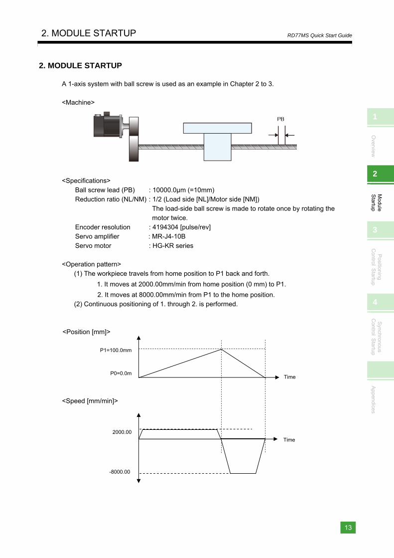
2. MODULE STARTUP
A 1-axis system with ball screw is used as an example in Chapter 2 to 3.
<Machine>
<Specifications>
Ball screw lead (PB) : 10000.0μm (=10mm) Reduction ratio (NL/NM) : 1/2 (Load side [NL]/Motor side [NM])
The load-side ball screw is made to rotate once by rotating the
motor twice. Encoder resolution : 4194304 [pulse/rev] Servo amplifier : MR-J4-10B
Servo motor : HG-KR series
<Operation pattern>
(1) The workpiece travels from home position to P1 back and forth.
1. It moves at 2000.00mm/min from home position (0 mm) to P1.
2. It moves at 8000.00mm/min from P1 to the home position. (2) Continuous positioning of 1. through 2. is performed.
<Position [mm]>
<Speed [mm/min]>
2000.00
-8000.00
Time
Time
P1=100.0mm
P0=0.0m
2. MODULE STARTUP
14
RD77MS Quick Start Guide
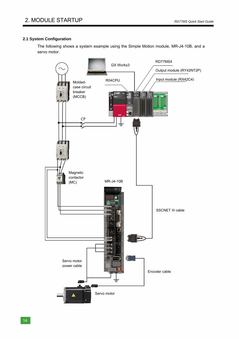
2.1 System Configuration
The following shows a system example using the Simple Motion module, MR-J4-10B, and a
servo motor.
Molded-case circuit breaker (MCCB)
Magnetic contactor (MC)
SSCNET III cable
Servo motor
Encoder cable
Servo motor power cable
MR-J4-10B
GX Works3
R04CPU
RD77MS4
Output module (RY42NT2P)
Input module (RX42C4)
1
Overview
2
Module
Startup
3
Positioning
Control S
tartup
4
Synchronous
Control S
tartup
Appendices
2. MODULE STARTUP
15
RD77MS Quick Start Guide
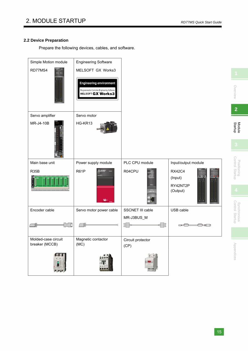
2.2 Device Preparation
Prepare the following devices, cables, and software.
Simple Motion module Engineering Software
RD77MS4 MELSOFT GX Works3
Servo amplifier Servo motor
MR-J4-10B
HG-KR13
Main base unit Power supply module PLC CPU module Input/output module
R35B
R61P
R04CPU
RX42C4
(Input) RY42NT2P (Output)
Encoder cable
Servo motor power cable
SSCNET III cable
MR-J3BUS_M
USB cable
Molded-case circuit breaker (MCCB)
Magnetic contactor (MC)
Circuit protector
(CP)
2. MODULE STARTUP
16
RD77MS Quick Start Guide
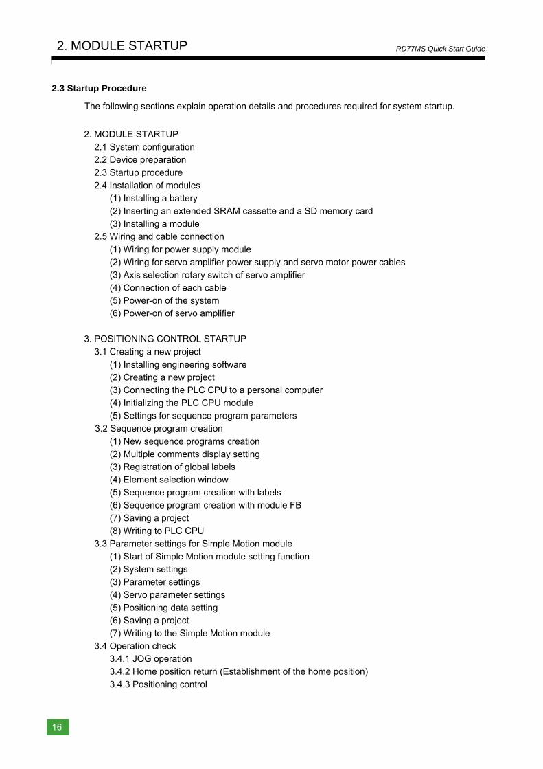
2.3 Startup Procedure
The following sections explain operation details and procedures required for system startup.
2. MODULE STARTUP 2.1 System configuration 2.2 Device preparation
2.3 Startup procedure 2.4 Installation of modules
(1) Installing a battery
(2) Inserting an extended SRAM cassette and a SD memory card (3) Installing a module
2.5 Wiring and cable connection
(1) Wiring for power supply module (2) Wiring for servo amplifier power supply and servo motor power cables (3) Axis selection rotary switch of servo amplifier
(4) Connection of each cable (5) Power-on of the system (6) Power-on of servo amplifier
3. POSITIONING CONTROL STARTUP
3.1 Creating a new project
(1) Installing engineering software (2) Creating a new project (3) Connecting the PLC CPU to a personal computer
(4) Initializing the PLC CPU module (5) Settings for sequence program parameters
3.2 Sequence program creation
(1) New sequence programs creation (2) Multiple comments display setting (3) Registration of global labels
(4) Element selection window (5) Sequence program creation with labels (6) Sequence program creation with module FB
(7) Saving a project (8) Writing to PLC CPU
3.3 Parameter settings for Simple Motion module
(1) Start of Simple Motion module setting function (2) System settings (3) Parameter settings
(4) Servo parameter settings (5) Positioning data setting (6) Saving a project
(7) Writing to the Simple Motion module 3.4 Operation check
3.4.1 JOG operation
3.4.2 Home position return (Establishment of the home position) 3.4.3 Positioning control
1
Overview
2
Module
Startup
3
Positioning
Control S
tartup
4
Synchronous
Control S
tartup
Appendices
2. MODULE STARTUP
17
RD77MS Quick Start Guide
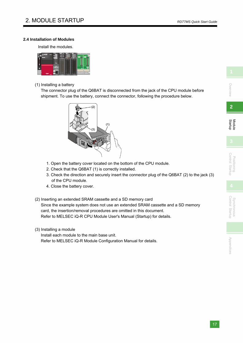
2.4 Installation of Modules
Install the modules.
(1) Installing a battery
The connector plug of the Q6BAT is disconnected from the jack of the CPU module before shipment. To use the battery, connect the connector, following the procedure below.
1. Open the battery cover located on the bottom of the CPU module. 2. Check that the Q6BAT (1) is correctly installed.
3. Check the direction and securely insert the connector plug of the Q6BAT (2) to the jack (3) of the CPU module.
4. Close the battery cover.
(2) Inserting an extended SRAM cassette and a SD memory card Since the example system does not use an extended SRAM cassette and a SD memory card, the insertion/removal procedures are omitted in this document.
Refer to MELSEC iQ-R CPU Module User's Manual (Startup) for details.
(3) Installing a module Install each module to the main base unit.
Refer to MELSEC iQ-R Module Configuration Manual for details.
2. MODULE STARTUP
18
RD77MS Quick Start Guide
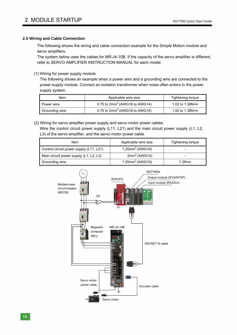
2.5 Wiring and Cable Connection
The following shows the wiring and cable connection example for the Simple Motion module and
servo amplifiers. The system below uses the cables for MR-J4-10B. If the capacity of the servo amplifier is different, refer to SERVO AMPLIFIER INSTRUCTION MANUAL for each model.
(1) Wiring for power supply module The following shows an example when a power wire and a grounding wire are connected to the
power supply module. Connect an isolation transformer when noise often enters in the power supply system.
Item Applicable wire size Tightening torque
Power wire 0.75 to 2mm2 (AWG18 to AWG14) 1.02 to 1.38N•m
Grounding wire 0.75 to 2mm2 (AWG18 to AWG14) 1.02 to 1.38N•m
(2) Wiring for servo amplifier power supply and servo motor power cables
Wire the control circuit power supply (L11, L21) and the main circuit power supply (L1, L2, L3) of the servo amplifier, and the servo motor power cable.
Item Applicable wire size Tightening torque
Control circuit power supply (L11, L21) 1.25mm2 (AWG16) -
Main circuit power supply (L1, L2, L3) 2mm2 (AWG14) -
Grounding wire 1.25mm2 (AWG16) 1.2N•m
Molded-case circuit breaker (MCCB)
Magnetic
contactor
(MC)
SSCNET III cable
Servo motor
Encoder cable
Servo motor
power cable
MR-J4-10B
R04CPU
RD77MS4
Output module (RY42NT2P)
Input module (RX42C4)
CP
1
Overview
2
Module
Startup
3
Positioning
Control S
tartup
4
Synchronous
Control S
tartup
Appendices
2. MODULE STARTUP
19
RD77MS Quick Start Guide
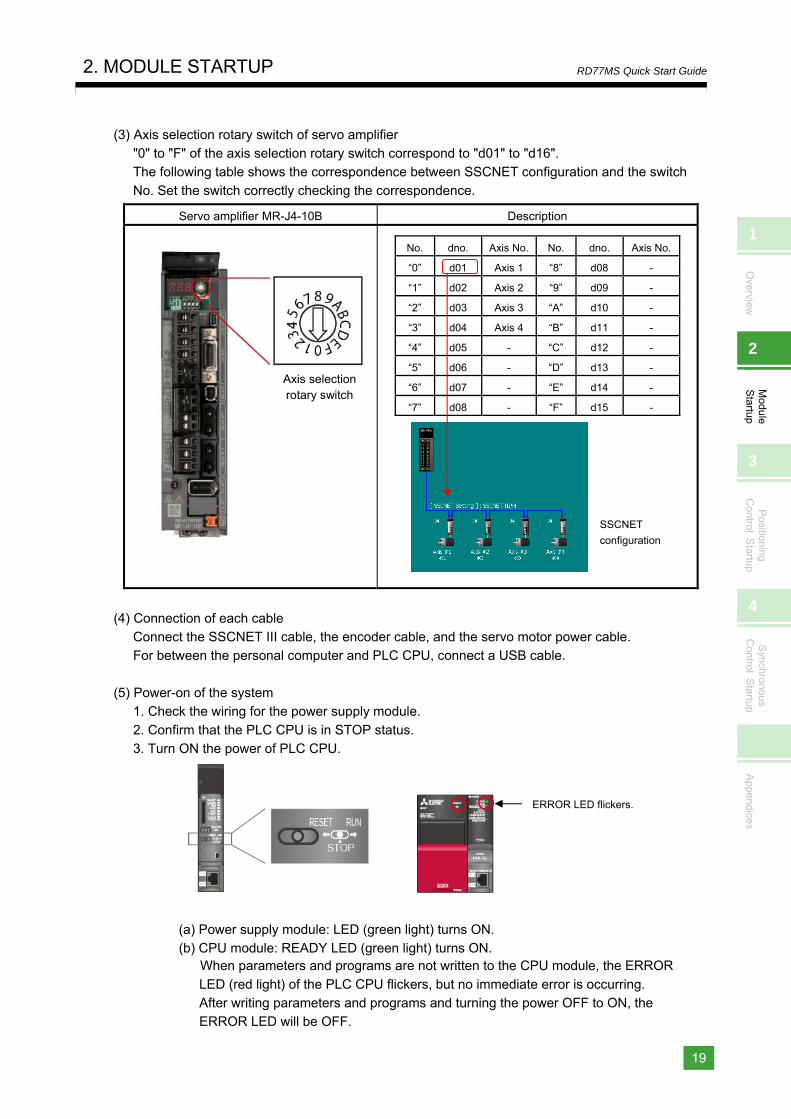
(3) Axis selection rotary switch of servo amplifier "0" to "F" of the axis selection rotary switch correspond to "d01" to "d16". The following table shows the correspondence between SSCNET configuration and the switch
No. Set the switch correctly checking the correspondence.
Servo amplifier MR-J4-10B Description
No. dno. Axis No. No. dno. Axis No.
“0” d01 Axis 1 “8” d08 -
“1” d02 Axis 2 “9” d09 -
“2” d03 Axis 3 “A” d10 -
“3” d04 Axis 4 “B” d11 -
“4” d05 - “C” d12 -
“5” d06 - “D” d13 -
“6” d07 - “E” d14 -
“7” d08 - “F” d15 -
(4) Connection of each cable Connect the SSCNET III cable, the encoder cable, and the servo motor power cable. For between the personal computer and PLC CPU, connect a USB cable.
(5) Power-on of the system 1. Check the wiring for the power supply module.
2. Confirm that the PLC CPU is in STOP status. 3. Turn ON the power of PLC CPU.
(a) Power supply module: LED (green light) turns ON. (b) CPU module: READY LED (green light) turns ON.
When parameters and programs are not written to the CPU module, the ERROR
LED (red light) of the PLC CPU flickers, but no immediate error is occurring. After writing parameters and programs and turning the power OFF to ON, the ERROR LED will be OFF.
ERROR LED flickers.
Axis selection rotary switch
SSCNET
configuration
2. MODULE STARTUP
20
RD77MS Quick Start Guide
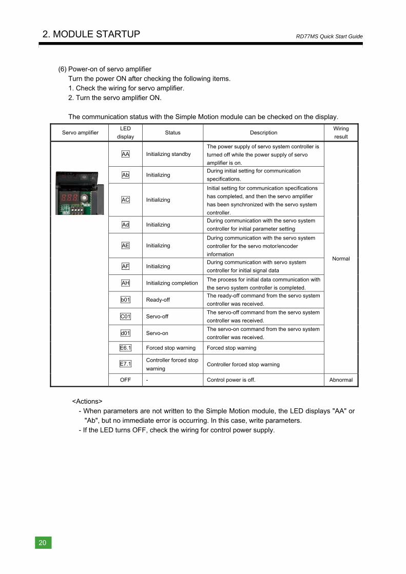
(6) Power-on of servo amplifier Turn the power ON after checking the following items. 1. Check the wiring for servo amplifier.
2. Turn the servo amplifier ON. The communication status with the Simple Motion module can be checked on the display.
Servo amplifier LED
display Status Description
Wiring
result
AA Initializing standby The power supply of servo system controller is
turned off while the power supply of servo
amplifier is on.
Normal
Ab Initializing During initial setting for communication
specifications.
AC Initializing
Initial setting for communication specifications
has completed, and then the servo amplifier
has been synchronized with the servo system
controller.
Ad Initializing During communication with the servo system
controller for initial parameter setting
AE Initializing
During communication with the servo system
controller for the servo motor/encoder
information
AF Initializing During communication with servo system
controller for initial signal data
AH Initializing completionThe process for initial data communication with
the servo system controller is completed.
b01 Ready-off The ready-off command from the servo system
controller was received.
C01 Servo-off The servo-off command from the servo system
controller was received.
d01 Servo-on The servo-on command from the servo system
controller was received.
E6.1 Forced stop warning Forced stop warning
E7.1 Controller forced stop
warning Controller forced stop warning
OFF - Control power is off. Abnormal
<Actions>
- When parameters are not written to the Simple Motion module, the LED displays "AA" or "Ab", but no immediate error is occurring. In this case, write parameters.
- If the LED turns OFF, check the wiring for control power supply.
1
Overview
2
Module
Startup
3
Positioning
Control S
tartup
4
Synchronous
Control S
tartup
Appendices
3. POSITIONING CONTROL STARTUP
21
RD77MS Quick Start Guide
3. POSITIONING CONTROL STARTUP
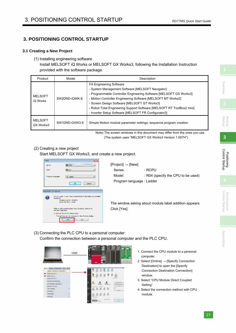
3.1 Creating a New Project
(1) Installing engineering software Install MELSOFT iQ Works or MELSOFT GX Works3, following the Installation Instruction
provided with the software package.
Product Model Description
MELSOFT
iQ Works SW2DND-iQWK-E
FA Engineering Software
- System Management Software [MELSOFT Navigator]
- Programmable Controller Engineering Software [MELSOFT GX Works3]
- Motion Controller Engineering Software [MELSOFT MT Works2]
- Screen Design Software [MELSOFT GT Works3]
- Robot Total Engineering Support Software [MELSOFT RT ToolBox2 mini]
- Inverter Setup Software [MELSOFT FR Configurator2]
MELSOFT
GX Works3 SW1DND-GXW3-E Simple Motion module parameter settings, sequence program creation
Note) The screen windows in this document may differ from the ones you use.
(The system uses “MELSOFT GX Works3 Version 1.007H”)
(2) Creating a new project
Start MELSOFT GX Works3, and create a new project.
(3) Connecting the PLC CPU to a personal computer Confirm the connection between a personal computer and the PLC CPU.
1. Connect the CPU module to a personal
computer.
2. Select [Online] → [Specify Connection
Destination] to open the [Specify
Connection Destination Connection]
window.
3. Select “CPU Module Direct Coupled
Setting”.
4. Select the connection method with CPU
module.
[Project] → [New]
Series : RCPU
Model : R04 (specify the CPU to be used)
Program language : Ladder
The window asking about module label addition appears.
Click [Yes].
3. POSITIONING CONTROL STARTUP
22
RD77MS Quick Start Guide
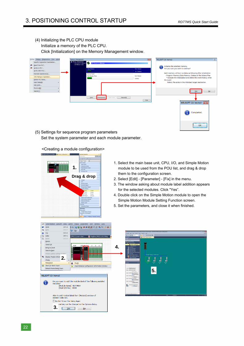
(4) Initializing the PLC CPU module Initialize a memory of the PLC CPU.
Click [Initialization] on the Memory Management window.
(5) Settings for sequence program parameters
Set the system parameter and each module parameter.
<Creating a module configuration>
1. Select the main base unit, CPU, I/O, and Simple Motion
module to be used from the POU list, and drag & drop
them to the configuration screen.
2. Select [Edit] - [Parameter] - [Fix] in the menu.
3. The window asking about module label addition appears
for the selected modules. Click "Yes”.
4. Double click on the Simple Motion module to open the
Simple Motion Module Setting Function screen.
5. Set the parameters, and close it when finished.
Drag & drop
1.
3.
2.
4.
5.
1
Overview
2
Module
Startup
3
Positioning
Control S
tartup
4
Synchronous
Control S
tartup
Appendices
3. POSITIONING CONTROL STARTUP
23
RD77MS Quick Start Guide
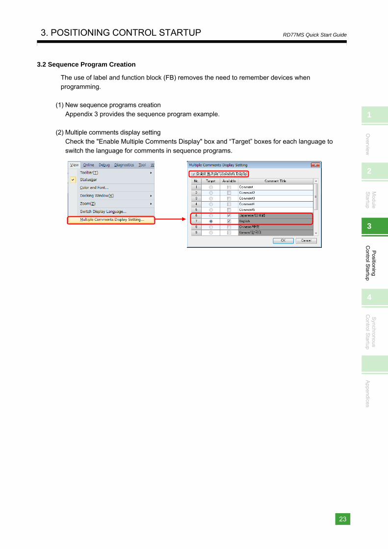
3.2 Sequence Program Creation
The use of label and function block (FB) removes the need to remember devices when programming.
(1) New sequence programs creation Appendix 3 provides the sequence program example.
(2) Multiple comments display setting Check the "Enable Multiple Comments Display" box and “Target” boxes for each language to
switch the language for comments in sequence programs.
3. POSITIONING CONTROL STARTUP
24
RD77MS Quick Start Guide
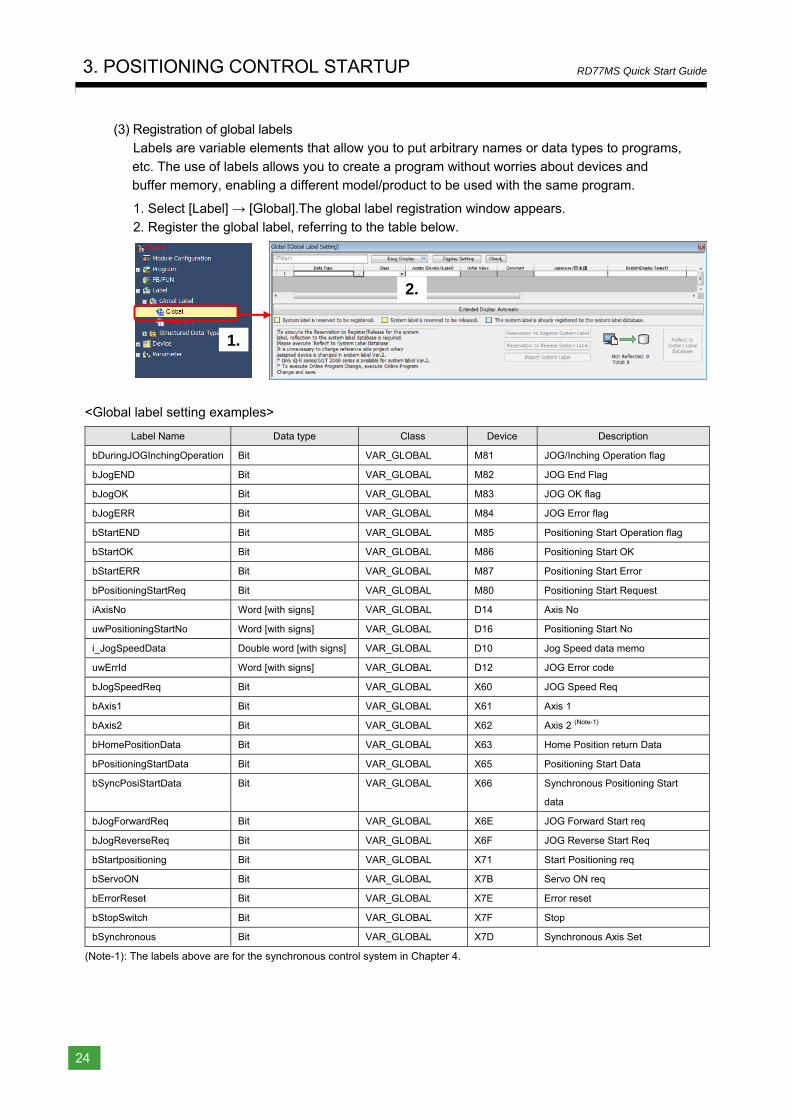
(3) Registration of global labels Labels are variable elements that allow you to put arbitrary names or data types to programs,
etc. The use of labels allows you to create a program without worries about devices and buffer memory, enabling a different model/product to be used with the same program.
1. Select [Label] → [Global].The global label registration window appears. 2. Register the global label, referring to the table below.
<Global label setting examples>
Label Name Data type Class Device Description
bDuringJOGInchingOperation Bit VAR_GLOBAL M81 JOG/Inching Operation flag
bJogEND Bit VAR_GLOBAL M82 JOG End Flag
bJogOK Bit VAR_GLOBAL M83 JOG OK flag
bJogERR Bit VAR_GLOBAL M84 JOG Error flag
bStartEND Bit VAR_GLOBAL M85 Positioning Start Operation flag
bStartOK Bit VAR_GLOBAL M86 Positioning Start OK
bStartERR Bit VAR_GLOBAL M87 Positioning Start Error
bPositioningStartReq Bit VAR_GLOBAL M80 Positioning Start Request
iAxisNo Word [with signs] VAR_GLOBAL D14 Axis No
uwPositioningStartNo Word [with signs] VAR_GLOBAL D16 Positioning Start No
i_JogSpeedData Double word [with signs] VAR_GLOBAL D10 Jog Speed data memo
uwErrId Word [with signs] VAR_GLOBAL D12 JOG Error code
bJogSpeedReq Bit VAR_GLOBAL X60 JOG Speed Req
bAxis1 Bit VAR_GLOBAL X61 Axis 1
bAxis2 Bit VAR_GLOBAL X62 Axis 2 (Note-1)
bHomePositionData Bit VAR_GLOBAL X63 Home Position return Data
bPositioningStartData Bit VAR_GLOBAL X65 Positioning Start Data
bSyncPosiStartData Bit VAR_GLOBAL X66 Synchronous Positioning Start
data
bJogForwardReq Bit VAR_GLOBAL X6E JOG Forward Start req
bJogReverseReq Bit VAR_GLOBAL X6F JOG Reverse Start Req
bStartpositioning Bit VAR_GLOBAL X71 Start Positioning req
bServoON Bit VAR_GLOBAL X7B Servo ON req
bErrorReset Bit VAR_GLOBAL X7E Error reset
bStopSwitch Bit VAR_GLOBAL X7F Stop
bSynchronous Bit VAR_GLOBAL X7D Synchronous Axis Set
(Note-1): The labels above are for the synchronous control system in Chapter 4.
1.
2.
1
Overview
2
Module
Startup
3
Positioning
Control S
tartup
4
Synchronous
Control S
tartup
Appendices
3. POSITIONING CONTROL STARTUP
25
RD77MS Quick Start Guide
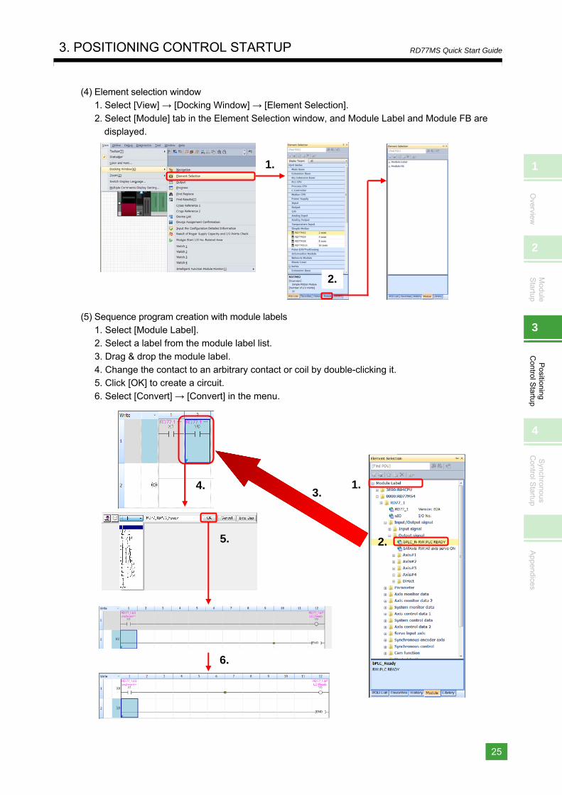
(4) Element selection window 1. Select [View] → [Docking Window] → [Element Selection].
2. Select [Module] tab in the Element Selection window, and Module Label and Module FB are displayed.
(5) Sequence program creation with module labels 1. Select [Module Label]. 2. Select a label from the module label list.
3. Drag & drop the module label. 4. Change the contact to an arbitrary contact or coil by double-clicking it. 5. Click [OK] to create a circuit.
6. Select [Convert] → [Convert] in the menu.
1.
2.
2.
1.
5.
6.
3.4.
3. POSITIONING CONTROL STARTUP
26
RD77MS Quick Start Guide
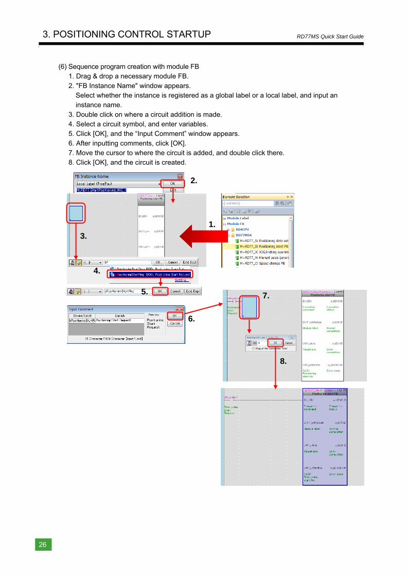
(6) Sequence program creation with module FB 1. Drag & drop a necessary module FB.
2. "FB Instance Name" window appears. Select whether the instance is registered as a global label or a local label, and input an instance name.
3. Double click on where a circuit addition is made. 4. Select a circuit symbol, and enter variables. 5. Click [OK], and the “Input Comment” window appears.
6. After inputting comments, click [OK]. 7. Move the cursor to where the circuit is added, and double click there. 8. Click [OK], and the circuit is created.
2.
1.
5.
8.
3.
4.
7.
6.
1
Overview
2
Module
Startup
3
Positioning
Control S
tartup
4
Synchronous
Control S
tartup
Appendices
3. POSITIONING CONTROL STARTUP
27
RD77MS Quick Start Guide
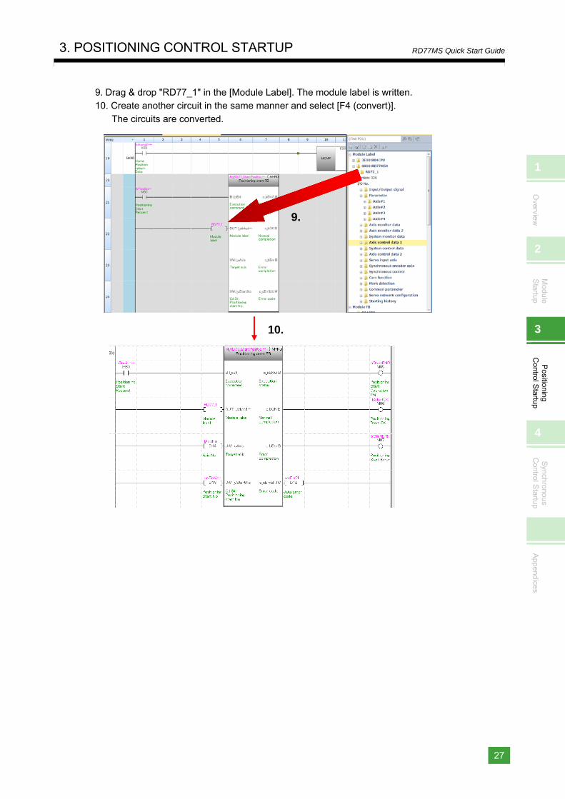
9. Drag & drop "RD77_1" in the [Module Label]. The module label is written. 10. Create another circuit in the same manner and select [F4 (convert)].
The circuits are converted.
10.
9.
3. POSITIONING CONTROL STARTUP
28
RD77MS Quick Start Guide
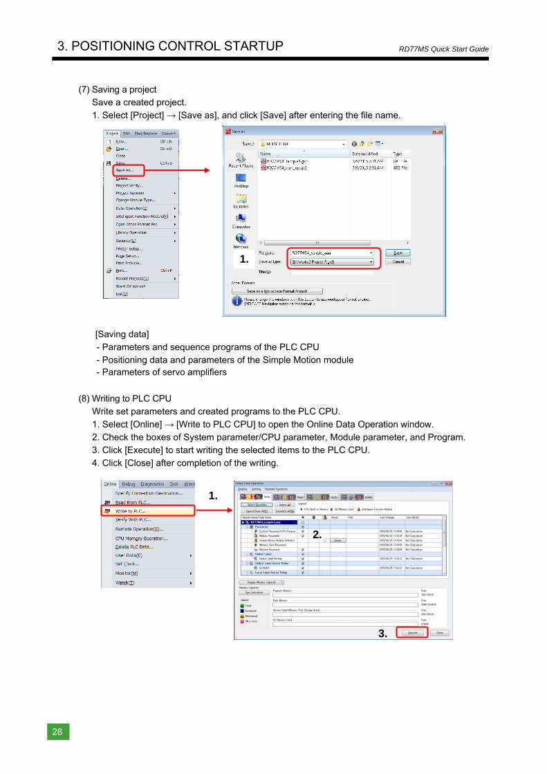
(7) Saving a project Save a created project.
1. Select [Project] → [Save as], and click [Save] after entering the file name.
[Saving data]
- Parameters and sequence programs of the PLC CPU - Positioning data and parameters of the Simple Motion module - Parameters of servo amplifiers
(8) Writing to PLC CPU Write set parameters and created programs to the PLC CPU.
1. Select [Online] → [Write to PLC CPU] to open the Online Data Operation window. 2. Check the boxes of System parameter/CPU parameter, Module parameter, and Program. 3. Click [Execute] to start writing the selected items to the PLC CPU.
4. Click [Close] after completion of the writing.
1.
2.
1.
3.
1
Overview
2
Module
Startup
3
Positioning
Control S
tartup
4
Synchronous
Control S
tartup
Appendices
3. POSITIONING CONTROL STARTUP
29
RD77MS Quick Start Guide
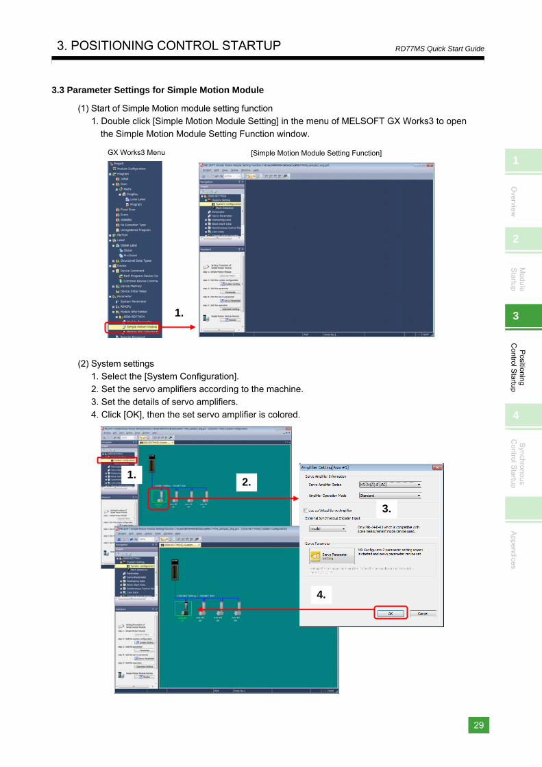
3.3 Parameter Settings for Simple Motion Module
(1) Start of Simple Motion module setting function 1. Double click [Simple Motion Module Setting] in the menu of MELSOFT GX Works3 to open
the Simple Motion Module Setting Function window.
(2) System settings 1. Select the [System Configuration]. 2. Set the servo amplifiers according to the machine.
3. Set the details of servo amplifiers. 4. Click [OK], then the set servo amplifier is colored.
GX Works3 Menu [Simple Motion Module Setting Function]
1.
2.1.
3.
4.
3. POSITIONING CONTROL STARTUP
30
RD77MS Quick Start Guide
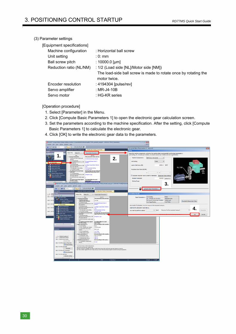
(3) Parameter settings
[Equipment specifications] Machine configuration : Horizontal ball screw Unit setting : 0: mm
Ball screw pitch : 10000.0 [μm] Reduction ratio (NL/NM) : 1/2 (Load side [NL]/Motor side [NM])
The load-side ball screw is made to rotate once by rotating the
motor twice. Encoder resolution : 4194304 [pulse/rev] Servo amplifier : MR-J4-10B
Servo motor : HG-KR series
[Operation procedure]
1. Select [Parameter] in the Menu. 2. Click [Compute Basic Parameters 1] to open the electronic gear calculation screen. 3. Set the parameters according to the machine specification. After the setting, click [Compute
Basic Parameters 1] to calculate the electronic gear. 4. Click [OK] to write the electronic gear data to the parameters.
2.1.
3.
4.
1
Overview
2
Module
Startup
3
Positioning
Control S
tartup
4
Synchronous
Control S
tartup
Appendices
3. POSITIONING CONTROL STARTUP
31
RD77MS Quick Start Guide
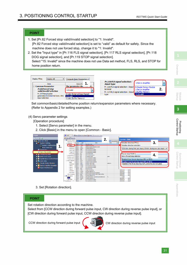
POINT
1. Set [Pr.82 Forced stop valid/invalid selection] to "1: Invalid". [Pr.82 Forced stop valid/invalid selection] is set to “valid” as default for safety. Since the
machine does not use forced stop, change it to "1: Invalid". 2. Set the "Input type" in [Pr.116 FLS signal selection], [Pr.117 RLS signal selection], [Pr.118
DOG signal selection], and [Pr.119 STOP signal selection]. Select "15: Invalid" since the machine does not use Data set method, FLS, RLS, and STOP for home position return.
Set common/basic/detailed/home position return/expansion parameters where necessary. (Refer to Appendix 2 for setting examples.)
(4) Servo parameter settings
[Operation procedure] 1. Select [Servo parameter] in the menu. 2. Click [Basic] in the menu to open [Common - Basic].
3. Set [Rotation direction].
POINT
Set rotation direction according to the machine. Select from [CCW direction during forward pulse input, CW direction during reverse pulse input], or [CW direction during forward pulse input, CCW direction during reverse pulse input].
2.
1.
4.
3.
CCW direction during forward pulse input CW direction during reverse pulse input
2.
1.
3. POSITIONING CONTROL STARTUP
32
RD77MS Quick Start Guide
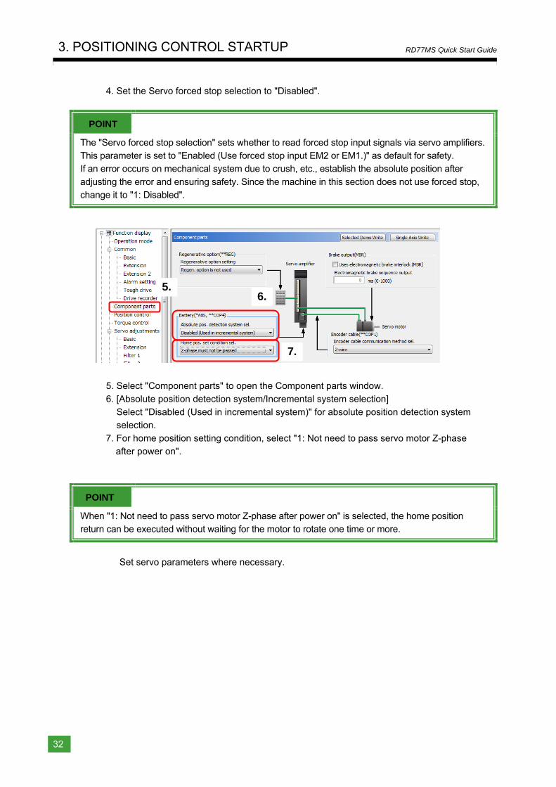
4. Set the Servo forced stop selection to "Disabled".
POINT
The "Servo forced stop selection" sets whether to read forced stop input signals via servo amplifiers. This parameter is set to "Enabled (Use forced stop input EM2 or EM1.)" as default for safety. If an error occurs on mechanical system due to crush, etc., establish the absolute position after
adjusting the error and ensuring safety. Since the machine in this section does not use forced stop, change it to "1: Disabled".
5. Select "Component parts" to open the Component parts window.
6. [Absolute position detection system/Incremental system selection] Select "Disabled (Used in incremental system)" for absolute position detection system selection.
7. For home position setting condition, select "1: Not need to pass servo motor Z-phase after power on".
POINT
When "1: Not need to pass servo motor Z-phase after power on" is selected, the home position return can be executed without waiting for the motor to rotate one time or more.
Set servo parameters where necessary.
5.6.
7.
1
Overview
2
Module
Startup
3
Positioning
Control S
tartup
4
Synchronous
Control S
tartup
Appendices
3. POSITIONING CONTROL STARTUP
33
RD77MS Quick Start Guide
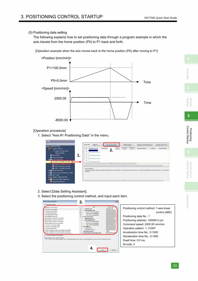
(5) Positioning data setting The following explains how to set positioning data through a program example in which the
axis travels from the home position (P0) to P1 back and forth.
[Operation example when the axis moves back to the home position (P0) after moving to P1]
[Operation procedure] 1. Select "Axis #1 Positioning Data" in the menu.
2. Select [Data Setting Assistant].
3. Select the positioning control method, and input each item.
<Position [mm/min]>
P1=100.0mm
P0=0.0mm
2000.00
<Speed [mm/min]>
-8000.00
Time
Time
Positioning control method: 1-axis linear
control (ABS)
Positioning data No.: 1
Positioning address: 100000.0 μm
Command speed: 2000.00 mm/min
Operation pattern: 1: CONT
Acceleration time No.: 0:1000
Deceleration time No.: 0:1000
Dwell time: 0:0 ms
M-code: 0
2.1.
3.
4.
3. POSITIONING CONTROL STARTUP
34
RD77MS Quick Start Guide
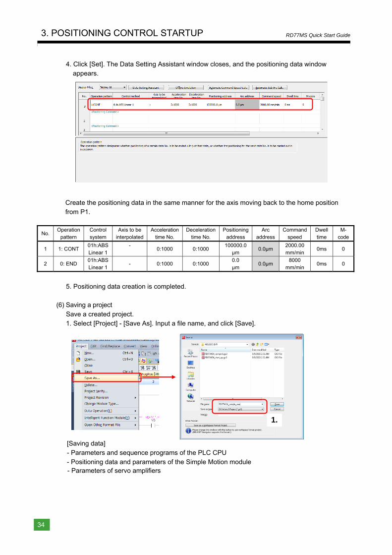
4. Click [Set]. The Data Setting Assistant window closes, and the positioning data window appears.
Create the positioning data in the same manner for the axis moving back to the home position from P1.
No. Operation
pattern Control system
Axis to be interpolated
Acceleration time No.
Deceleration time No.
Positioning address
Arc address
Command speed
Dwell time
M-code
1 1: CONT 01h:ABS Linear 1
-
0:1000 0:1000 100000.0
μm 0.0μm
2000.00 mm/min
0ms 0
2 0: END 01h:ABS Linear 1
- 0:1000 0:1000 0.0 μm
0.0μm 8000
mm/min 0ms 0
5. Positioning data creation is completed.
(6) Saving a project
Save a created project. 1. Select [Project] - [Save As]. Input a file name, and click [Save].
[Saving data]
- Parameters and sequence programs of the PLC CPU - Positioning data and parameters of the Simple Motion module - Parameters of servo amplifiers
1.
1
Overview
2
Module
Startup
3
Positioning
Control S
tartup
4
Synchronous
Control S
tartup
Appendices
3. POSITIONING CONTROL STARTUP
35
RD77MS Quick Start Guide
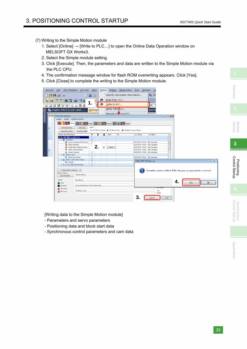
(7) Writing to the Simple Motion module 1. Select [Online] → [Write to PLC…] to open the Online Data Operation window on
MELSOFT GX Works3. 2. Select the Simple module setting. 3. Click [Execute]. Then, the parameters and data are written to the Simple Motion module via
the PLC CPU. 4. The confirmation message window for flash ROM overwriting appears. Click [Yes]. 5. Click [Close] to complete the writing to the Simple Motion module.
[Writing data to the Simple Motion module] - Parameters and servo parameters
- Positioning data and block start data - Synchronous control parameters and cam data
2.
1.
3.
4.
3. POSITIONING CONTROL STARTUP
36
RD77MS Quick Start Guide
3.4 Operation Check
The sequence program used in this section is an example using R04CPU and RD77MS4. When another different module is used, the signal assignment differs. Refer to MELSEC iQ-R
Simple Motion Module User's Manual (Application) for details of each signal.
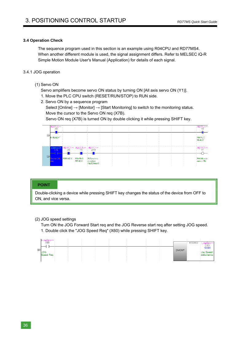
3.4.1 JOG operation
(1) Servo ON Servo amplifiers become servo ON status by turning ON [All axis servo ON (Y1)]. 1. Move the PLC CPU switch (RESET/RUN/STOP) to RUN side.
2. Servo ON by a sequence program Select [Online] → [Monitor] → [Start Monitoring] to switch to the monitoring status. Move the cursor to the Servo ON req (X7B).
Servo ON req (X7B) is turned ON by double clicking it while pressing SHIFT key.
POINT
Double-clicking a device while pressing SHIFT key changes the status of the device from OFF to
ON, and vice versa.
(2) JOG speed settings
Turn ON the JOG Forward Start req and the JOG Reverse start req after setting JOG speed. 1. Double click the "JOG Speed Req" (X60) while pressing SHIFT key.
1
Overview
2
Module
Startup
3
Positioning
Control S
tartup
4
Synchronous
Control S
tartup
Appendices
3. POSITIONING CONTROL STARTUP
37
RD77MS Quick Start Guide
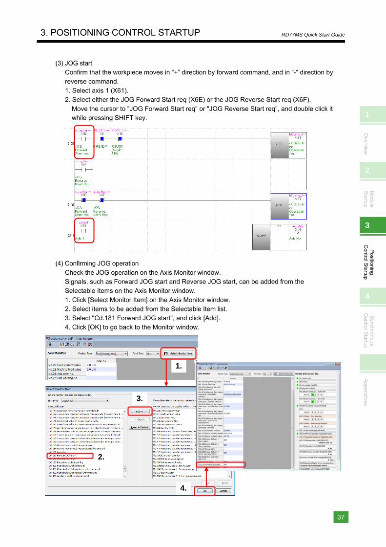
(3) JOG start Confirm that the workpiece moves in “+” direction by forward command, and in “-“ direction by
reverse command. 1. Select axis 1 (X61). 2. Select either the JOG Forward Start req (X6E) or the JOG Reverse Start req (X6F).
Move the cursor to "JOG Forward Start req" or "JOG Reverse Start req", and double click it while pressing SHIFT key.
(4) Confirming JOG operation
Check the JOG operation on the Axis Monitor window. Signals, such as Forward JOG start and Reverse JOG start, can be added from the Selectable Items on the Axis Monitor window.
1. Click [Select Monitor Item] on the Axis Monitor window. 2. Select items to be added from the Selectable Item list. 3. Select "Cd.181 Forward JOG start", and click [Add].
4. Click [OK] to go back to the Monitor window.
2.
1.
4.
3.
3. POSITIONING CONTROL STARTUP
38
RD77MS Quick Start Guide
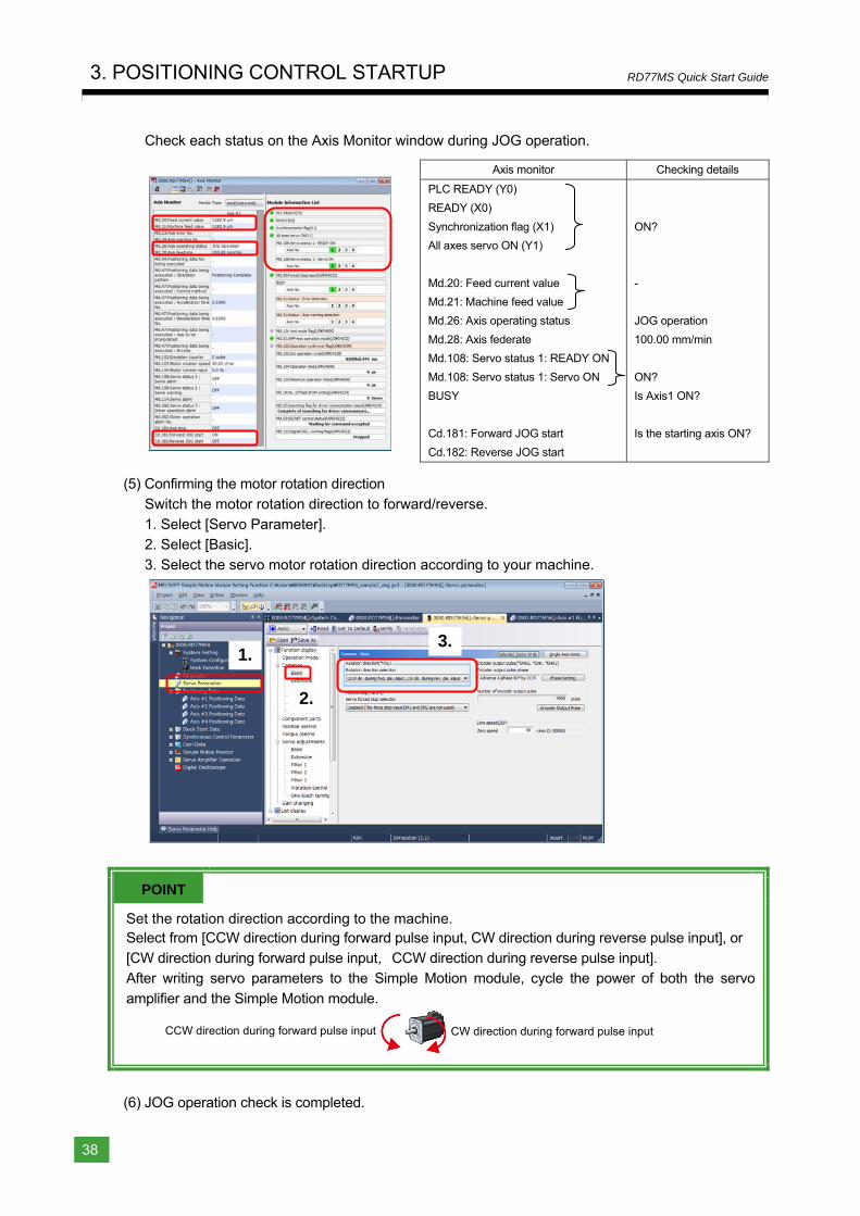
Check each status on the Axis Monitor window during JOG operation.
Axis monitor Checking details
PLC READY (Y0)
READY (X0)
Synchronization flag (X1)
All axes servo ON (Y1)
Md.20: Feed current value
Md.21: Machine feed value
Md.26: Axis operating status
Md.28: Axis federate
Md.108: Servo status 1: READY ON
Md.108: Servo status 1: Servo ON
BUSY
Cd.181: Forward JOG start
Cd.182: Reverse JOG start
ON?
-
JOG operation
100.00 mm/min
ON?
Is Axis1 ON?
Is the starting axis ON?
(5) Confirming the motor rotation direction
Switch the motor rotation direction to forward/reverse. 1. Select [Servo Parameter]. 2. Select [Basic].
3. Select the servo motor rotation direction according to your machine.
POINT
Set the rotation direction according to the machine. Select from [CCW direction during forward pulse input, CW direction during reverse pulse input], or [CW direction during forward pulse input,CCW direction during reverse pulse input]. After writing servo parameters to the Simple Motion module, cycle the power of both the servo
amplifier and the Simple Motion module.
(6) JOG operation check is completed.
2.
1. 3.
CCW direction during forward pulse input CW direction during forward pulse input
1
Overview
2
Module
Startup
3
Positioning
Control S
tartup
4
Synchronous
Control S
tartup
Appendices
3. POSITIONING CONTROL STARTUP
39
RD77MS Quick Start Guide
3.4.2 Home position return (Establishment of the home position)
There are two types of home position return control:
- Machine home position return which does not use address information to establish the home position.
- Fast home position return which performs positioning by using the coordinate defined by
machine home position. This document explains the method of performing the machine home position return using Data set method.
After setting "9001" as the positioning start No., the home position return is started by turning ON the Positioning start signal.
Item Buffer memory Signal Description
Axis 1 positioning start No. 4300 - Set the positioning start No. Set “9001”
for machine home position return.
Axis 1 positioning start - Y10 Execute the home position return and
positioning start.
POINT
After setting "9001" as the positioning start No., the machine home position return is started by turning ON the Positioning start.
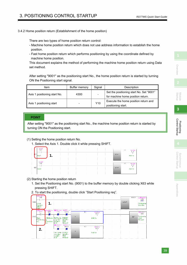
(1) Setting the home position return No.
1. Select the Axis 1. Double click it while pressing SHIFT.
(2) Starting the home position return
1. Set the Positioning start No. (9001) to the buffer memory by double clicking X63 while pressing SHIFT.
2. To start the positioning, double click ”Start Positioning req”.
1.
1.
2.
1.
2.
3. POSITIONING CONTROL STARTUP
40
RD77MS Quick Start Guide
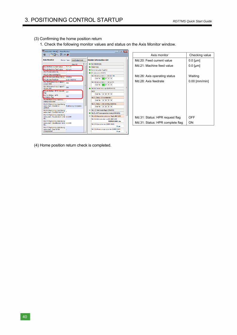
(3) Confirming the home position return 1. Check the following monitor values and status on the Axis Monitor window.
Axis monitor Checking value
Md.20: Feed current value
Md.21: Machine feed value
Md.26: Axis operating status
Md.28: Axis feedrate
Md.31: Status: HPR request flag
Md.31: Status: HPR complete flag
0.0 [μm]
0.0 [μm]
Waiting
0.00 [mm/min]
OFF
ON
(4) Home position return check is completed.
1
Overview
2
Module
Startup
3
Positioning
Control S
tartup
4
Synchronous
Control S
tartup
Appendices
3. POSITIONING CONTROL STARTUP
41
RD77MS Quick Start Guide
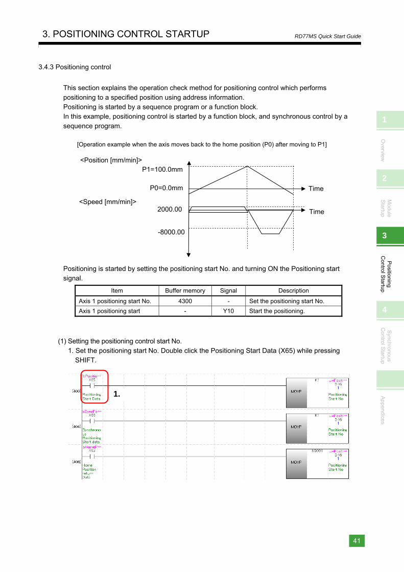
3.4.3 Positioning control
This section explains the operation check method for positioning control which performs
positioning to a specified position using address information. Positioning is started by a sequence program or a function block. In this example, positioning control is started by a function block, and synchronous control by a
sequence program.
[Operation example when the axis moves back to the home position (P0) after moving to P1]
Positioning is started by setting the positioning start No. and turning ON the Positioning start signal.
Item Buffer memory Signal Description
Axis 1 positioning start No. 4300 - Set the positioning start No.
Axis 1 positioning start - Y10 Start the positioning.
(1) Setting the positioning control start No. 1. Set the positioning start No. Double click the Positioning Start Data (X65) while pressing
SHIFT.
2000.00<Speed [mm/min]>
-8000.00
P1=100.0mm
P0=0.0mm
<Position [mm/min]>
Time
Time
1.
3. POSITIONING CONTROL STARTUP
42
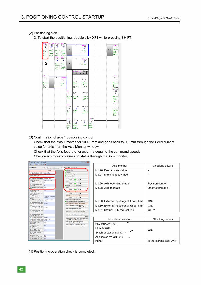
RD77MS Quick Start Guide
(2) Positioning start 2. To start the positioning, double click X71 while pressing SHIFT.
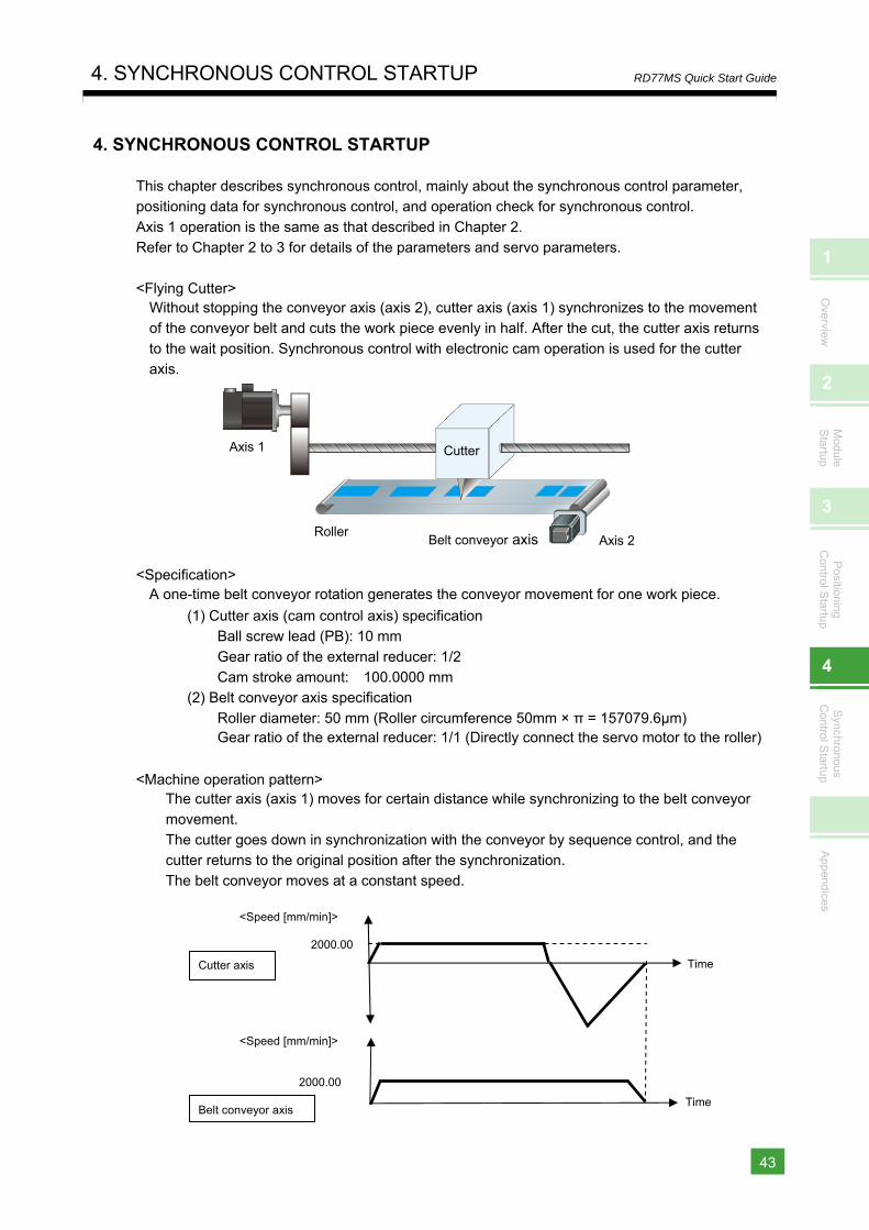
(3) Confirmation of axis 1 positioning control
Check that the axis 1 moves for 100.0 mm and goes back to 0.0 mm through the Feed current value for axis 1 on the Axis Monitor window. Check that the Axis feedrate for axis 1 is equal to the command speed.
Check each monitor value and status through the Axis monitor.
Axis monitor Checking details
Md.20: Feed current value
Md.21: Machine feed value
Md.26: Axis operating status
Md.28: Axis feedrate
Md.30: External input signal: Lower limit
Md.30: External input signal: Upper limit
Md.31: Status: HPR request flag
-
-
Position control
2000.00 [mm/min]
ON?
ON?
OFF?
Module information Checking details
PLC READY (Y0)
READY (X0)
Synchronization flag (X1)
All axes servo ON (Y1)
BUSY
ON?
Is the starting axis ON?
(4) Positioning operation check is completed.
2.
1
Overview
2
Module
Startup
3
Positioning
Control S
tartup
4
Synchronous
Control S
tartup
Appendices
4. SYNCHRONOUS CONTROL STARTUP
43
RD77MS Quick Start Guide
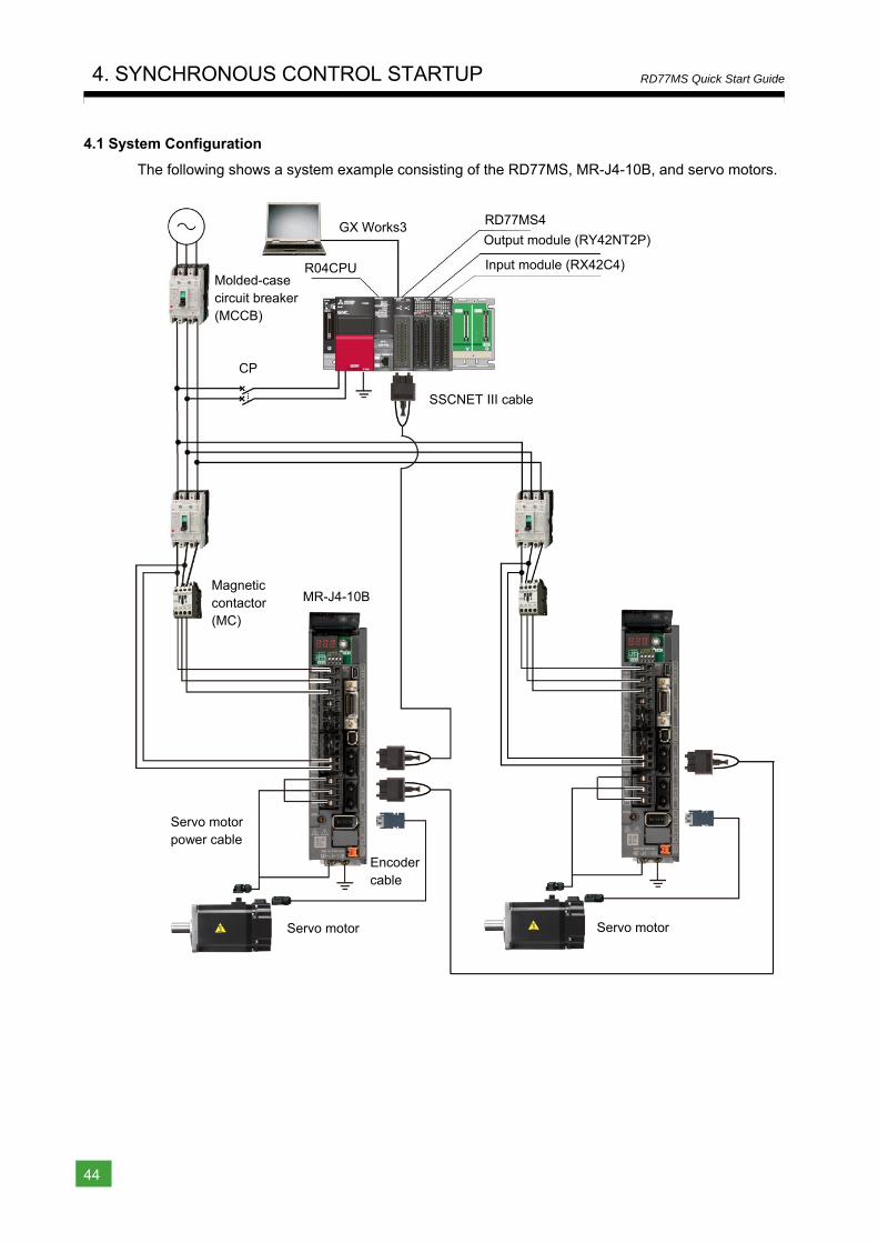
4. SYNCHRONOUS CONTROL STARTUP
This chapter describes synchronous control, mainly about the synchronous control parameter, positioning data for synchronous control, and operation check for synchronous control.
Axis 1 operation is the same as that described in Chapter 2. Refer to Chapter 2 to 3 for details of the parameters and servo parameters.
<Flying Cutter> Without stopping the conveyor axis (axis 2), cutter axis (axis 1) synchronizes to the movement of the conveyor belt and cuts the work piece evenly in half. After the cut, the cutter axis returns
to the wait position. Synchronous control with electronic cam operation is used for the cutter axis.
<Specification> A one-time belt conveyor rotation generates the conveyor movement for one work piece.
(1) Cutter axis (cam control axis) specification Ball screw lead (PB): 10 mm
Gear ratio of the external reducer: 1/2 Cam stroke amount: 100.0000 mm
(2) Belt conveyor axis specification
Roller diameter: 50 mm (Roller circumference 50mm × π = 157079.6μm) Gear ratio of the external reducer: 1/1 (Directly connect the servo motor to the roller)
<Machine operation pattern> The cutter axis (axis 1) moves for certain distance while synchronizing to the belt conveyor movement.
The cutter goes down in synchronization with the conveyor by sequence control, and the cutter returns to the original position after the synchronization. The belt conveyor moves at a constant speed.
2000.00
<Speed [mm/min]>
<Speed [mm/min]>
2000.00
Belt conveyor axis
Cutter axis
Time
Time
CutterAxis 1
Roller Belt conveyor axis Axis 2
4. SYNCHRONOUS CONTROL STARTUP
44
RD77MS Quick Start Guide
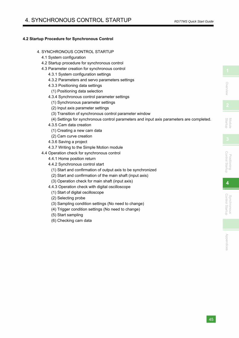
4.1 System Configuration
The following shows a system example consisting of the RD77MS, MR-J4-10B, and servo motors.
Molded-case circuit breaker (MCCB)
Magnetic contactor (MC)
SSCNET III cable
Servo motor
Encoder cable
Servo motor power cable
MR-J4-10B
GX Works3
R04CPU
RD77MS4
Output module (RY42NT2P)
Input module (RX42C4)
CP
Servo motor
1
Overview
2
Module
Startup
3
Positioning
Control S
tartup
4
Synchronous
Control S
tartup
Appendices
4. SYNCHRONOUS CONTROL STARTUP
45
RD77MS Quick Start Guide
4.2 Startup Procedure for Synchronous Control
4. SYNCHRONOUS CONTROL STARTUP 4.1 System configuration 4.2 Startup procedure for synchronous control 4.3 Parameter creation for synchronous control
4.3.1 System configuration settings 4.3.2 Parameters and servo parameters settings 4.3.3 Positioning data settings
(1) Positioning data selection 4.3.4 Synchronous control parameter settings
(1) Synchronous parameter settings (2) Input axis parameter settings (3) Transition of synchronous control parameter window (4) Settings for synchronous control parameters and input axis parameters are completed.
4.3.5 Cam data creation (1) Creating a new cam data (2) Cam curve creation
4.3.6 Saving a project 4.3.7 Writing to the Simple Motion module
4.4 Operation check for synchronous control 4.4.1 Home position return 4.4.2 Synchronous control start
(1) Start and confirmation of output axis to be synchronized (2) Start and confirmation of the main shaft (input axis) (3) Operation check for main shaft (input axis)
4.4.3 Operation check with digital oscilloscope (1) Start of digital oscilloscope (2) Selecting probe (3) Sampling condition settings (No need to change) (4) Trigger condition settings (No need to change) (5) Start sampling (6) Checking cam data
4. SYNCHRONOUS CONTROL STARTUP
46
RD77MS Quick Start Guide
4.3 Parameter Creation for Synchronous Control
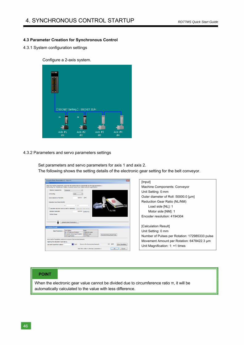
4.3.1 System configuration settings
Configure a 2-axis system.
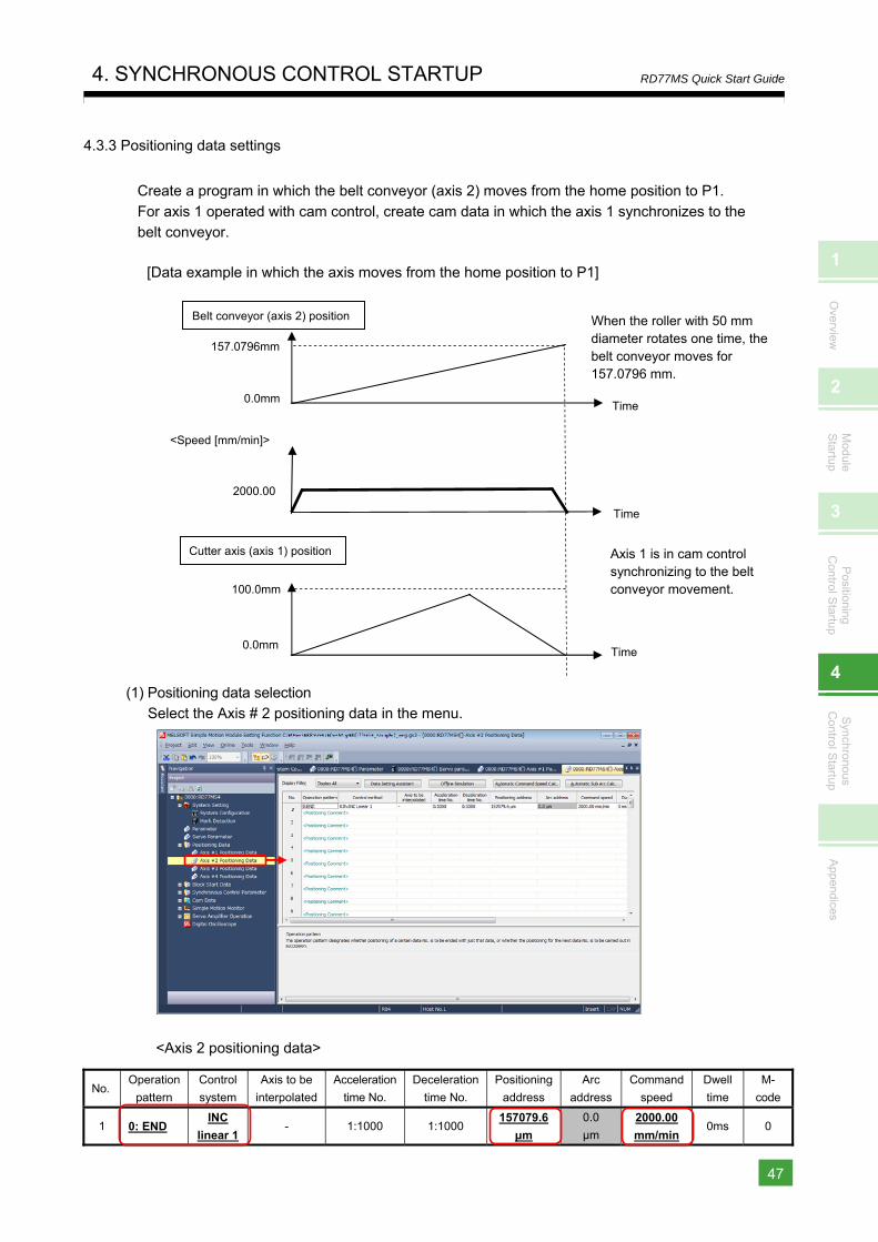
4.3.2 Parameters and servo parameters settings
Set parameters and servo parameters for axis 1 and axis 2.
The following shows the setting details of the electronic gear setting for the belt conveyor.
[Input]
Machine Components: Conveyor
Unit Setting: 0:mm
Outer diameter of Roll: 50000.0 [μm]
Reduction Gear Ratio (NL/NM)
Load side [NL]: 1
Motor side [NM]: 1
Encoder resolution: 4194304
[Calculation Result]
Unit Setting: 0 mm
Number of Pulses per Rotation: 172985333 pulse
Movement Amount per Rotation: 6478422.3 μm
Unit Magnification: 1: ×1 times
POINT
When the electronic gear value cannot be divided due to circumference ratio π, it will be automatically calculated to the value with less difference.
1
Overview
2
Module
Startup
3
Positioning
Control S
tartup
4
Synchronous
Control S
tartup
Appendices
4. SYNCHRONOUS CONTROL STARTUP
47
RD77MS Quick Start Guide
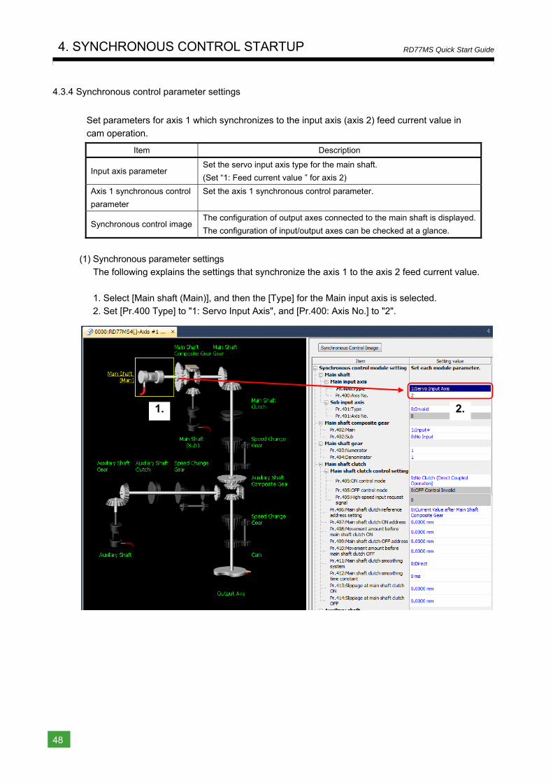
4.3.3 Positioning data settings
Create a program in which the belt conveyor (axis 2) moves from the home position to P1.
For axis 1 operated with cam control, create cam data in which the axis 1 synchronizes to the belt conveyor.
[Data example in which the axis moves from the home position to P1]
(1) Positioning data selection Select the Axis # 2 positioning data in the menu.
<Axis 2 positioning data>
No. Operation
pattern
Control
system
Axis to be
interpolated
Acceleration
time No.
Deceleration
time No.
Positioning
address
Arc
address
Command
speed
Dwell
time
M-
code
1 0: END INC
linear 1 - 1:1000 1:1000
157079.6
μm
0.0
μm
2000.00
mm/min 0ms 0
100.0mm
0.0mm
Cutter axis (axis 1) position
Belt conveyor (axis 2) position
157.0796mm
0.0mm
When the roller with 50 mm diameter rotates one time, the belt conveyor moves for 157.0796 mm.
Axis 1 is in cam control synchronizing to the belt conveyor movement.
Time
Time
<Speed [mm/min]>
2000.00
Time
4. SYNCHRONOUS CONTROL STARTUP
48
RD77MS Quick Start Guide
4.3.4 Synchronous control parameter settings
Set parameters for axis 1 which synchronizes to the input axis (axis 2) feed current value in
cam operation.
Item Description
Input axis parameter Set the servo input axis type for the main shaft.
(Set “1: Feed current value ” for axis 2)
Axis 1 synchronous control
parameter
Set the axis 1 synchronous control parameter.
Synchronous control image The configuration of output axes connected to the main shaft is displayed.
The configuration of input/output axes can be checked at a glance.
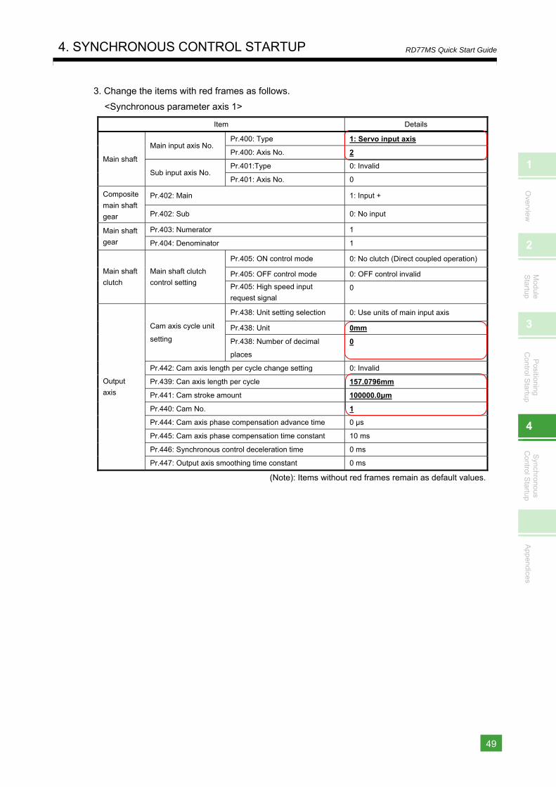
(1) Synchronous parameter settings The following explains the settings that synchronize the axis 1 to the axis 2 feed current value.
1. Select [Main shaft (Main)], and then the [Type] for the Main input axis is selected. 2. Set [Pr.400 Type] to "1: Servo Input Axis", and [Pr.400: Axis No.] to "2".
1. 2.
1
Overview
2
Module
Startup
3
Positioning
Control S
tartup
4
Synchronous
Control S
tartup
Appendices
4. SYNCHRONOUS CONTROL STARTUP
49
RD77MS Quick Start Guide
3. Change the items with red frames as follows.
<Synchronous parameter axis 1>
Item Details
Main shaft
Main input axis No. Pr.400: Type 1: Servo input axis
Pr.400: Axis No. 2
Sub input axis No. Pr.401:Type 0: Invalid
Pr.401: Axis No. 0
Composite
main shaft
gear
Pr.402: Main 1: Input +
Pr.402: Sub 0: No input
Main shaft
gear
Pr.403: Numerator 1
Pr.404: Denominator 1
Main shaft
clutch
Main shaft clutch
control setting
Pr.405: ON control mode 0: No clutch (Direct coupled operation)
Pr.405: OFF control mode 0: OFF control invalid
Pr.405: High speed input
request signal 0
Output
axis
Cam axis cycle unit
setting
Pr.438: Unit setting selection 0: Use units of main input axis
Pr.438: Unit 0mm
Pr.438: Number of decimal
places
0
Pr.442: Cam axis length per cycle change setting 0: Invalid
Pr.439: Can axis length per cycle 157.0796mm
Pr.441: Cam stroke amount 100000.0μm
Pr.440: Cam No. 1
Pr.444: Cam axis phase compensation advance time 0 μs
Pr.445: Cam axis phase compensation time constant 10 ms
Pr.446: Synchronous control deceleration time 0 ms
Pr.447: Output axis smoothing time constant 0 ms
(Note): Items without red frames remain as default values.
4. SYNCHRONOUS CONTROL STARTUP
50
RD77MS Quick Start Guide
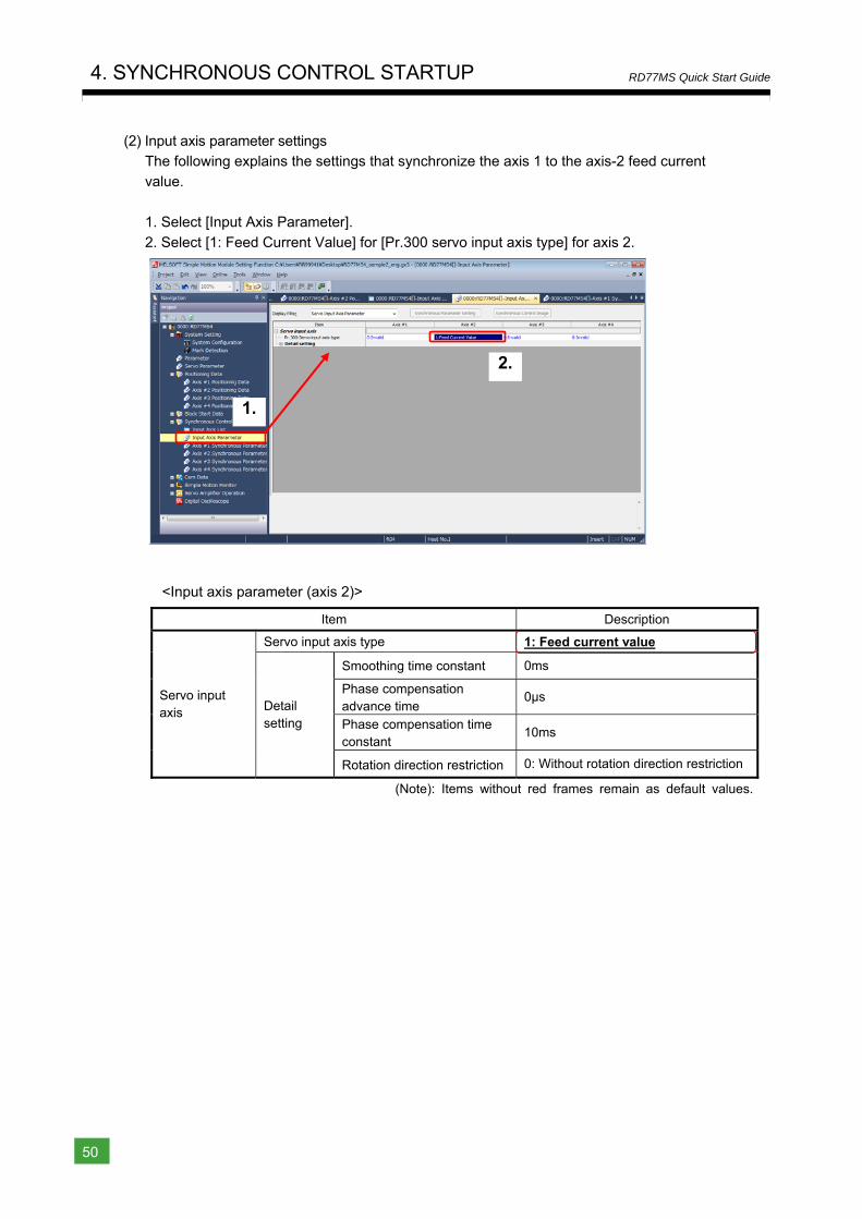
(2) Input axis parameter settings The following explains the settings that synchronize the axis 1 to the axis-2 feed current
value.
1. Select [Input Axis Parameter].
2. Select [1: Feed Current Value] for [Pr.300 servo input axis type] for axis 2.
<Input axis parameter (axis 2)>
Item Description
Servo input axis
Servo input axis type 1: Feed current value
Detail setting
Smoothing time constant 0ms
Phase compensation advance time
0μs
Phase compensation time constant
10ms
Rotation direction restriction 0: Without rotation direction restriction
(Note): Items without red frames remain as default values.
2.
1.
1
Overview
2
Module
Startup
3
Positioning
Control S
tartup
4
Synchronous
Control S
tartup
Appendices
4. SYNCHRONOUS CONTROL STARTUP
51
RD77MS Quick Start Guide
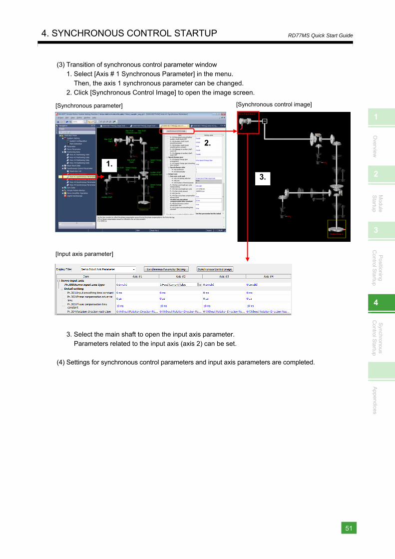
(3) Transition of synchronous control parameter window 1. Select [Axis # 1 Synchronous Parameter] in the menu.
Then, the axis 1 synchronous parameter can be changed. 2. Click [Synchronous Control Image] to open the image screen.
3. Select the main shaft to open the input axis parameter. Parameters related to the input axis (axis 2) can be set.
(4) Settings for synchronous control parameters and input axis parameters are completed.
[Synchronous parameter] [Synchronous control image]
2.
1.
3.
[Input axis parameter]
4. SYNCHRONOUS CONTROL STARTUP
52
RD77MS Quick Start Guide
4.3.5 Cam data creation
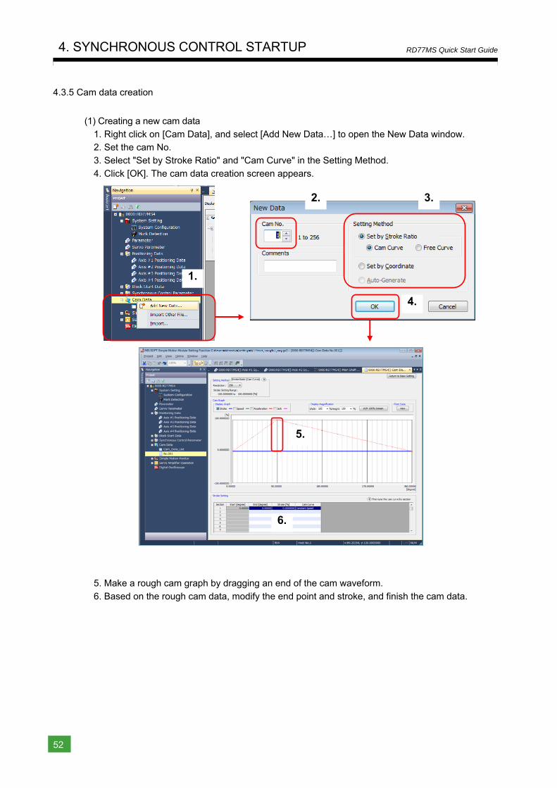
(1) Creating a new cam data
1. Right click on [Cam Data], and select [Add New Data…] to open the New Data window. 2. Set the cam No. 3. Select "Set by Stroke Ratio" and "Cam Curve" in the Setting Method.
4. Click [OK]. The cam data creation screen appears.
5. Make a rough cam graph by dragging an end of the cam waveform.
6. Based on the rough cam data, modify the end point and stroke, and finish the cam data.
2.
1.
3.
4.
5.
6.
1
Overview
2
Module
Startup
3
Positioning
Control S
tartup
4
Synchronous
Control S
tartup
Appendices
4. SYNCHRONOUS CONTROL STARTUP
53
RD77MS Quick Start Guide
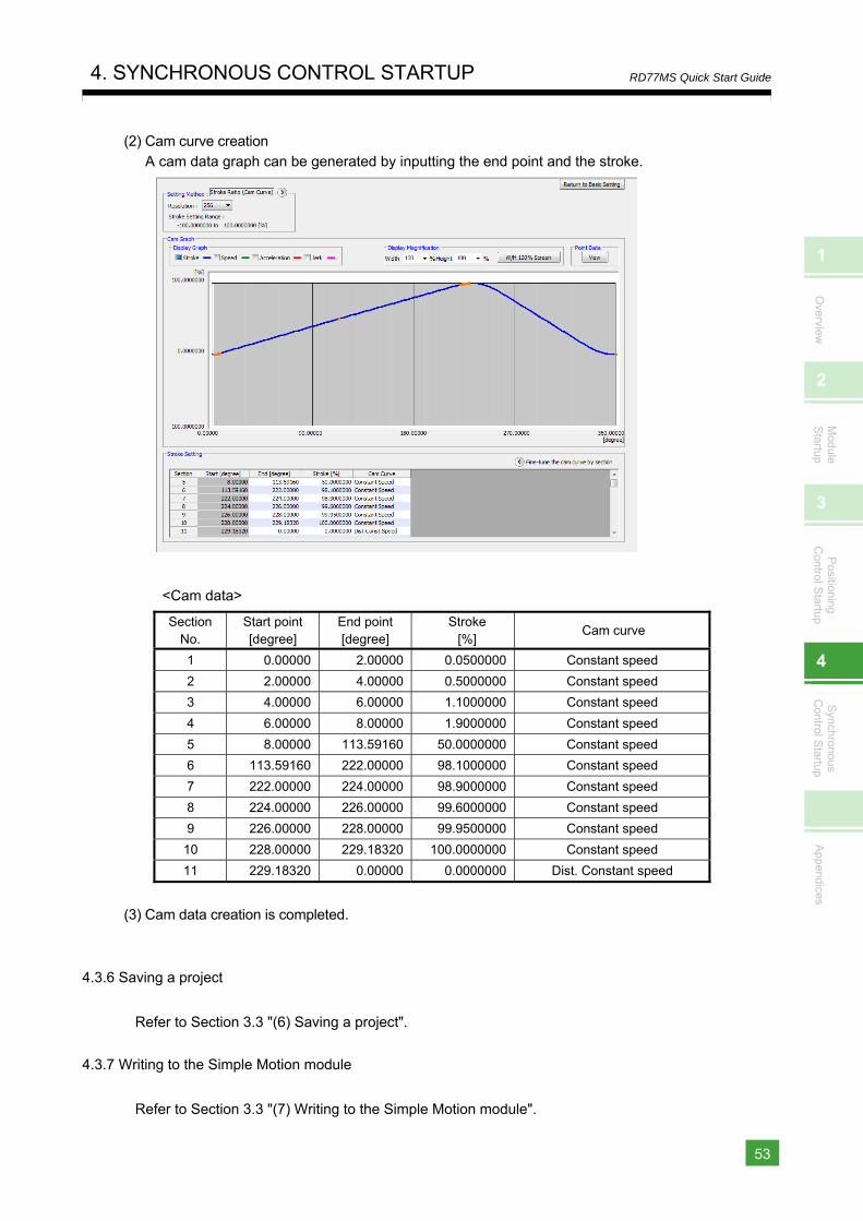
(2) Cam curve creation A cam data graph can be generated by inputting the end point and the stroke.
<Cam data>
Section No.
Start point [degree]
End point [degree]
Stroke [%]
Cam curve
1 0.00000 2.00000 0.0500000 Constant speed
2 2.00000 4.00000 0.5000000 Constant speed
3 4.00000 6.00000 1.1000000 Constant speed
4 6.00000 8.00000 1.9000000 Constant speed
5 8.00000 113.59160 50.0000000 Constant speed
6 113.59160 222.00000 98.1000000 Constant speed
7 222.00000 224.00000 98.9000000 Constant speed
8 224.00000 226.00000 99.6000000 Constant speed
9 226.00000 228.00000 99.9500000 Constant speed
10 228.00000 229.18320 100.0000000 Constant speed
11 229.18320 0.00000 0.0000000 Dist. Constant speed
(3) Cam data creation is completed.
4.3.6 Saving a project
Refer to Section 3.3 "(6) Saving a project".
4.3.7 Writing to the Simple Motion module
Refer to Section 3.3 "(7) Writing to the Simple Motion module".
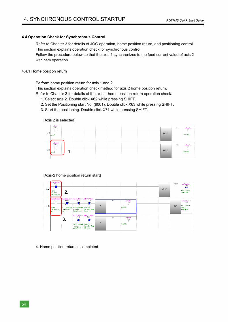
4. SYNCHRONOUS CONTROL STARTUP
54
RD77MS Quick Start Guide
4.4 Operation Check for Synchronous Control
Refer to Chapter 3 for details of JOG operation, home position return, and positioning control.
This section explains operation check for synchronous control. Follow the procedure below so that the axis 1 synchronizes to the feed current value of axis 2 with cam operation.
4.4.1 Home position return
Perform home position return for axis 1 and 2.
This section explains operation check method for axis 2 home position return. Refer to Chapter 3 for details of the axis-1 home position return operation check.
1. Select axis 2. Double click X62 while pressing SHIFT.
2. Set the Positioning start No. (9001). Double click X63 while pressing SHIFT. 3. Start the positioning. Double click X71 while pressing SHIFT.
[Axis 2 is selected]
[Axis-2 home position return start]
4. Home position return is completed.
1.
2.
3.
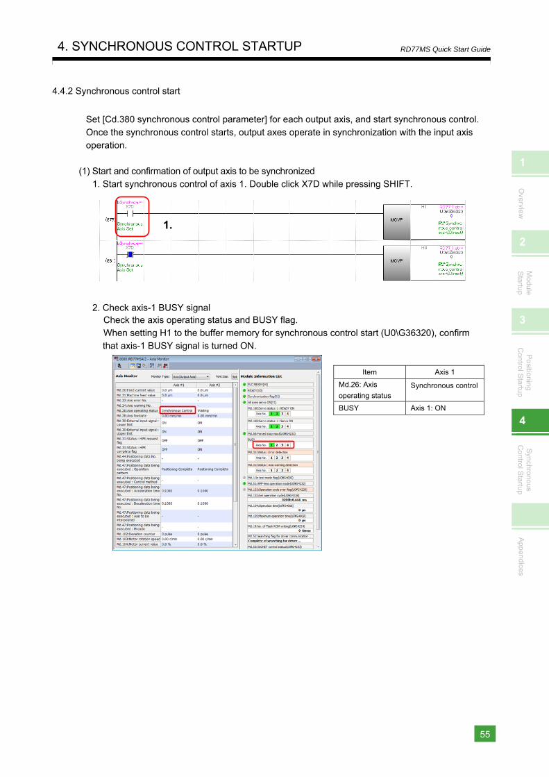
1
Overview
2
Module
Startup
3
Positioning
Control S
tartup
4
Synchronous
Control S
tartup
Appendices
4. SYNCHRONOUS CONTROL STARTUP
55
RD77MS Quick Start Guide
4.4.2 Synchronous control start
Set [Cd.380 synchronous control parameter] for each output axis, and start synchronous control.
Once the synchronous control starts, output axes operate in synchronization with the input axis operation.
(1) Start and confirmation of output axis to be synchronized 1. Start synchronous control of axis 1. Double click X7D while pressing SHIFT.
2. Check axis-1 BUSY signal Check the axis operating status and BUSY flag. When setting H1 to the buffer memory for synchronous control start (U0\G36320), confirm that axis-1 BUSY signal is turned ON.
Item Axis 1
Md.26: Axis
operating status Synchronous control
BUSY Axis 1: ON
1.
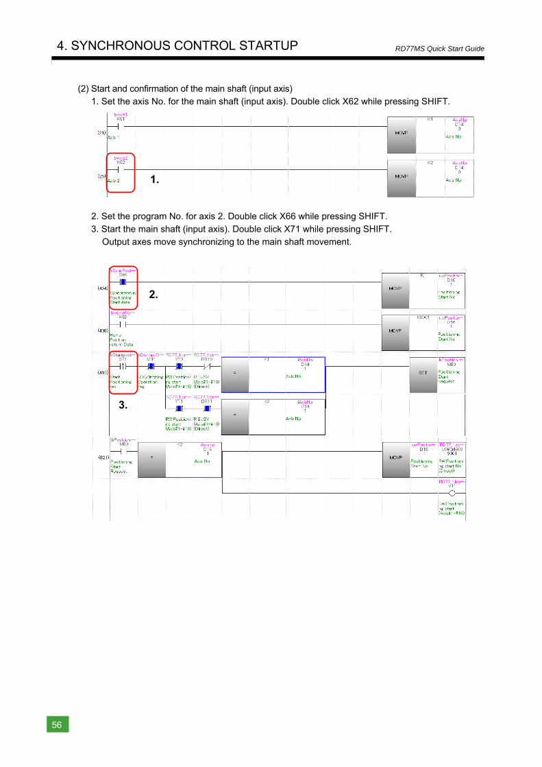
4. SYNCHRONOUS CONTROL STARTUP
56
RD77MS Quick Start Guide
(2) Start and confirmation of the main shaft (input axis) 1. Set the axis No. for the main shaft (input axis). Double click X62 while pressing SHIFT.
2. Set the program No. for axis 2. Double click X66 while pressing SHIFT.
3. Start the main shaft (input axis). Double click X71 while pressing SHIFT. Output axes move synchronizing to the main shaft movement.
2.
3.
1.
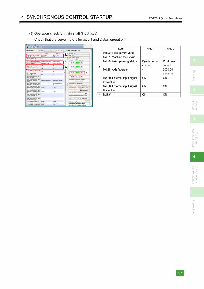
1
Overview
2
Module
Startup
3
Positioning
Control S
tartup
4
Synchronous
Control S
tartup
Appendices
4. SYNCHRONOUS CONTROL STARTUP
57
RD77MS Quick Start Guide
(3) Operation check for main shaft (input axis)
Check that the servo motors for axis 1 and 2 start operation.
Item Axis 1 Axis 2
1Md.20: Feed current value
Md.21: Machine feed value
-
-
-
-
2
Md.26: Axis operating status
Md.28: Axis federate
Synchronous
control
-
Positioning
control
2000.00
[mm/min]
3
Md.30: External input signal:
Lower limit
Md.30: External input signal:
Upper limit
ON
ON
ON
ON
4 BUSY ON ON
1.
2.
3.
4.
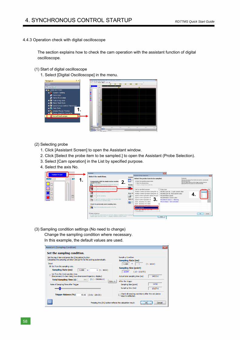
4. SYNCHRONOUS CONTROL STARTUP
58
RD77MS Quick Start Guide
4.4.3 Operation check with digital oscilloscope
The section explains how to check the cam operation with the assistant function of digital
oscilloscope.
(1) Start of digital oscilloscope
1. Select [Digital Oscilloscope] in the menu.
(2) Selecting probe
1. Click [Assistant Screen] to open the Assistant window. 2. Click [Select the probe item to be sampled.] to open the Assistant (Probe Selection). 3. Select [Cam operation] in the List by specified purpose.
4. Select the axis No.
(3) Sampling condition settings (No need to change) Change the sampling condition where necessary. In this example, the default values are used.
1.
1. 2.
3.4.
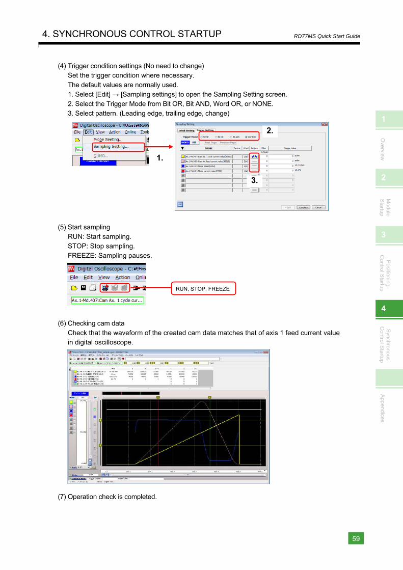
1
Overview
2
Module
Startup
3
Positioning
Control S
tartup
4
Synchronous
Control S
tartup
Appendices
4. SYNCHRONOUS CONTROL STARTUP
59
RD77MS Quick Start Guide
(4) Trigger condition settings (No need to change) Set the trigger condition where necessary.
The default values are normally used. 1. Select [Edit] → [Sampling settings] to open the Sampling Setting screen. 2. Select the Trigger Mode from Bit OR, Bit AND, Word OR, or NONE.
3. Select pattern. (Leading edge, trailing edge, change)
(5) Start sampling RUN: Start sampling. STOP: Stop sampling.
FREEZE: Sampling pauses.
(6) Checking cam data
Check that the waveform of the created cam data matches that of axis 1 feed current value in digital oscilloscope.
(7) Operation check is completed.
1.
2.
3.
RUN, STOP, FREEZE

4. SYNCHRONOUS CONTROL STARTUP
60
RD77MS Quick Start Guide
MEMO
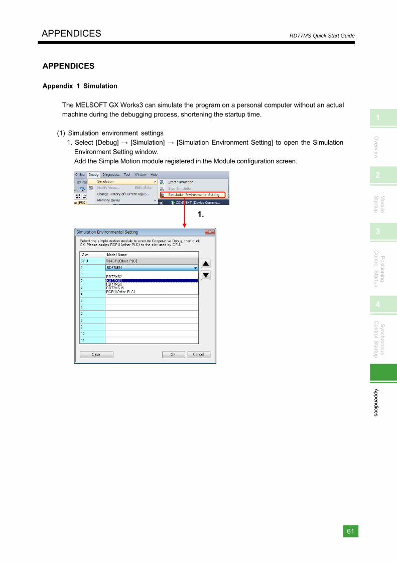
1
Overview
2
Module
Startup
3
Positioning
Control S
tartup
4
Synchronous
Control S
tartup
Appendices
APPENDICES
61
RD77MS Quick Start Guide
APPENDICES
Appendix 1 Simulation
The MELSOFT GX Works3 can simulate the program on a personal computer without an actual machine during the debugging process, shortening the startup time.
(1) Simulation environment settings 1. Select [Debug] → [Simulation] → [Simulation Environment Setting] to open the Simulation
Environment Setting window. Add the Simple Motion module registered in the Module configuration screen.
1.
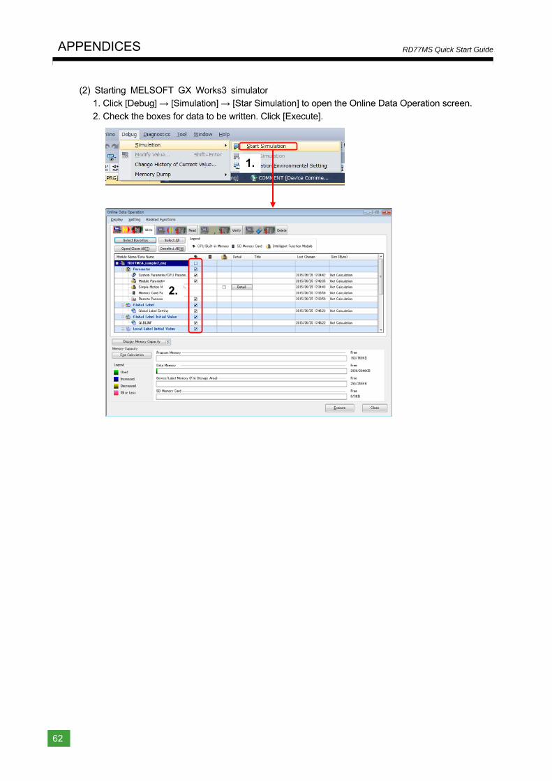
APPENDICES
62
RD77MS Quick Start Guide
(2) Starting MELSOFT GX Works3 simulator 1. Click [Debug] → [Simulation] → [Star Simulation] to open the Online Data Operation screen.
2. Check the boxes for data to be written. Click [Execute].
1.
2.
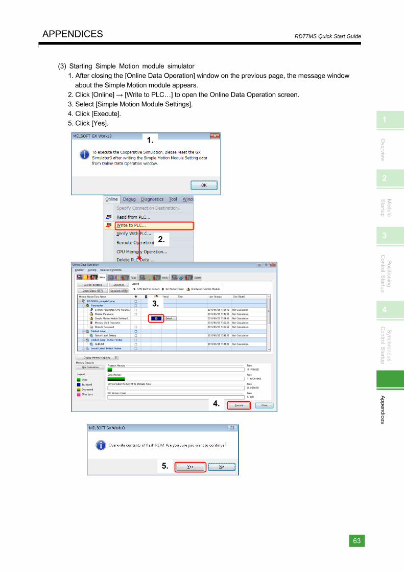
1
Overview
2
Module
Startup
3
Positioning
Control S
tartup
4
Synchronous
Control S
tartup
Appendices
APPENDICES
63
RD77MS Quick Start Guide
(3) Starting Simple Motion module simulator 1. After closing the [Online Data Operation] window on the previous page, the message window
about the Simple Motion module appears. 2. Click [Online] → [Write to PLC…] to open the Online Data Operation screen. 3. Select [Simple Motion Module Settings].
4. Click [Execute]. 5. Click [Yes].
1.
2.
5.
3.
4.
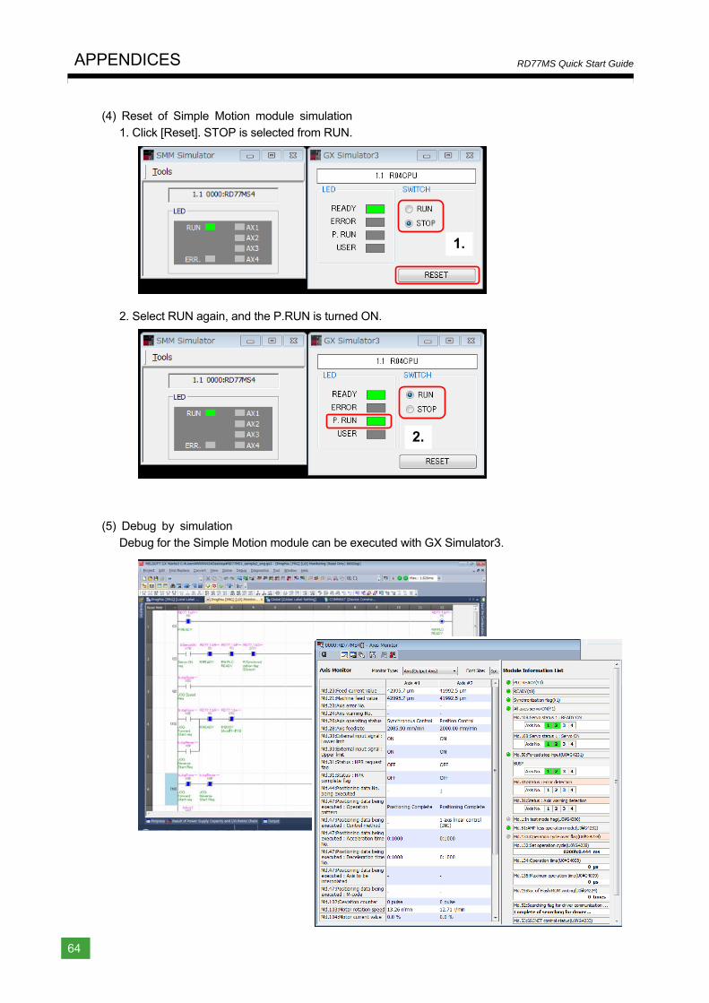
APPENDICES
64
RD77MS Quick Start Guide
(4) Reset of Simple Motion module simulation 1. Click [Reset]. STOP is selected from RUN.
2. Select RUN again, and the P.RUN is turned ON.
(5) Debug by simulation
Debug for the Simple Motion module can be executed with GX Simulator3.
1.
2.
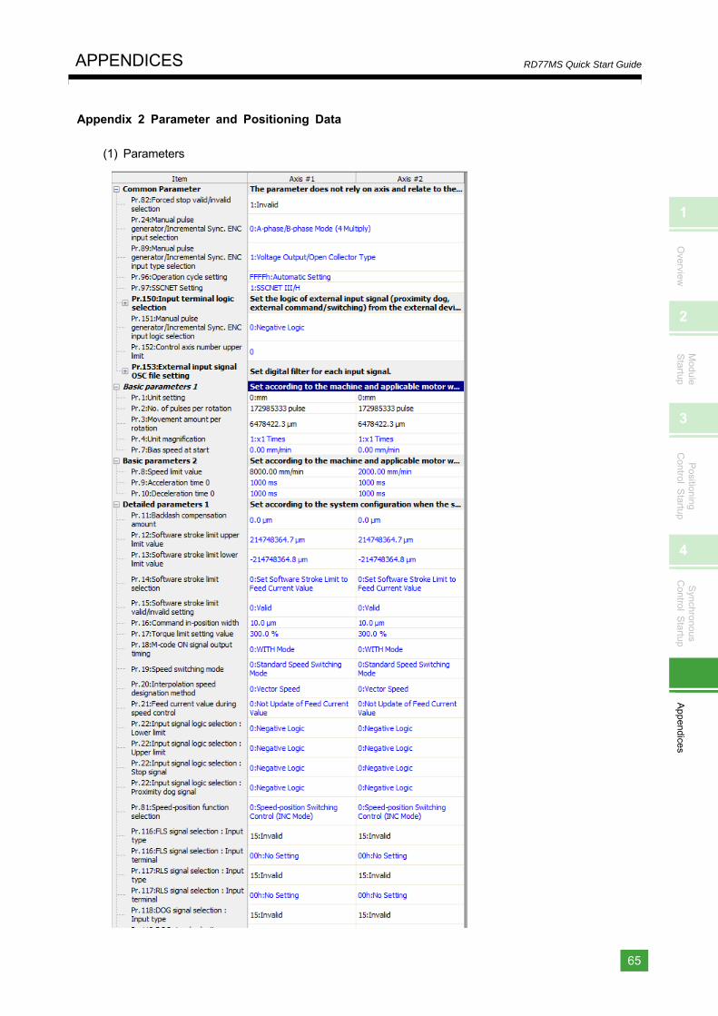
1
Overview
2
Module
Startup
3
Positioning
Control S
tartup
4
Synchronous
Control S
tartup
Appendices
APPENDICES
65
RD77MS Quick Start Guide
Appendix 2 Parameter and Positioning Data
(1) Parameters
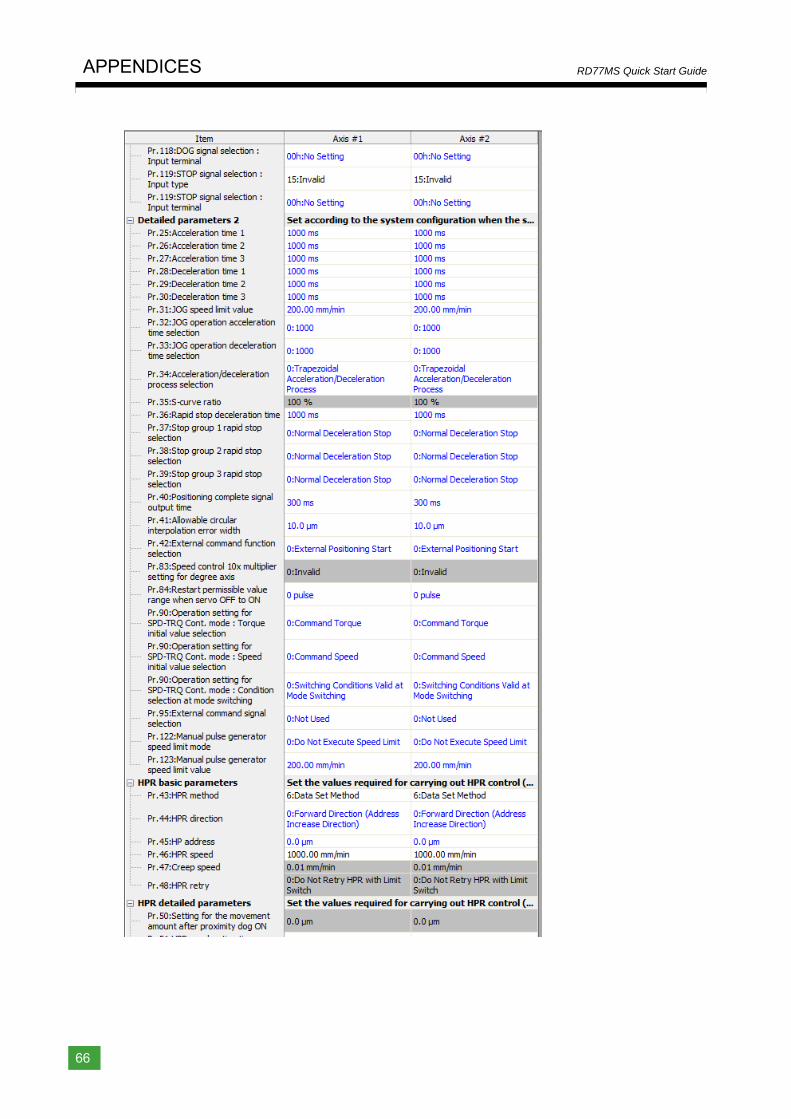
APPENDICES
66
RD77MS Quick Start Guide
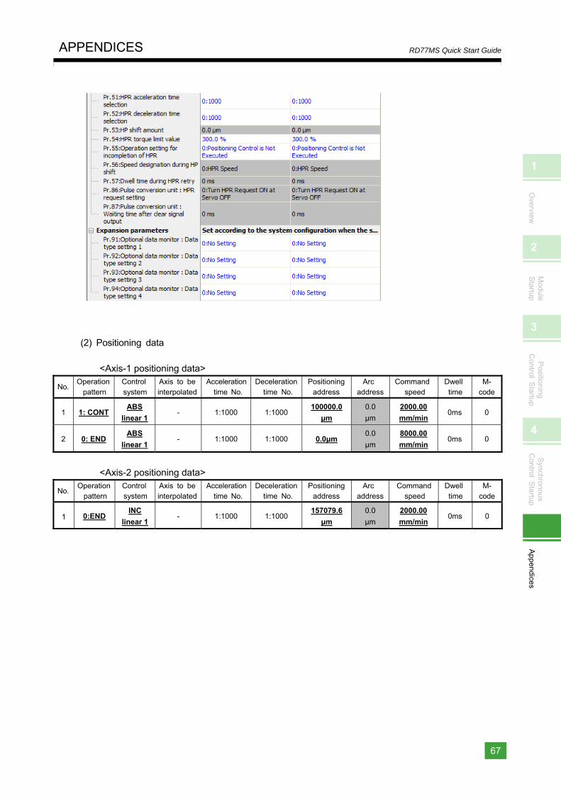
1
Overview
2
Module
Startup
3
Positioning
Control S
tartup
4
Synchronous
Control S
tartup
Appendices
APPENDICES
67
RD77MS Quick Start Guide
(2) Positioning data
<Axis-1 positioning data>
No. Operation
pattern Control system
Axis to be interpolated
Acceleration time No.
Deceleration time No.
Positioningaddress
Arc address
Command speed
Dwell time
M- code
1 1: CONT ABS
linear 1 - 1:1000 1:1000
100000.0
μm
0.0
μm
2000.00
mm/min 0ms 0
2 0: END ABS
linear 1 - 1:1000 1:1000 0.0μm
0.0
μm
8000.00
mm/min 0ms 0
<Axis-2 positioning data>
No. Operation
pattern Control system
Axis to be interpolated
Acceleration time No.
Deceleration time No.
Positioningaddress
Arc address
Command speed
Dwell time
M- code
1 0:END INC
linear 1 - 1:1000 1:1000
157079.6
μm
0.0
μm
2000.00
mm/min 0ms 0
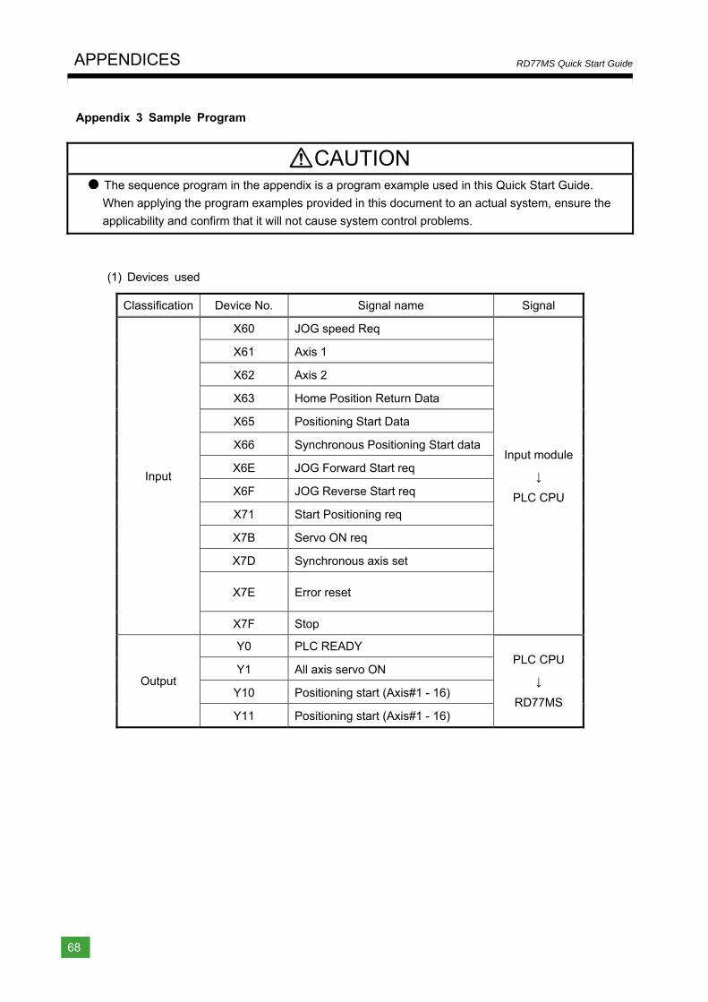
APPENDICES
68
RD77MS Quick Start Guide
Appendix 3 Sample Program
CAUTION The sequence program in the appendix is a program example used in this Quick Start Guide.
When applying the program examples provided in this document to an actual system, ensure the
applicability and confirm that it will not cause system control problems.
(1) Devices used
Classification Device No. Signal name Signal
Input
X60 JOG speed Req
Input module
↓
PLC CPU
X61 Axis 1
X62 Axis 2
X63 Home Position Return Data
X65 Positioning Start Data
X66 Synchronous Positioning Start data
X6E JOG Forward Start req
X6F JOG Reverse Start req
X71 Start Positioning req
X7B Servo ON req
X7D Synchronous axis set
X7E Error reset
X7F Stop
Output
Y0 PLC READY PLC CPU
↓
RD77MS
Y1 All axis servo ON
Y10 Positioning start (Axis#1 - 16)
Y11 Positioning start (Axis#1 - 16)
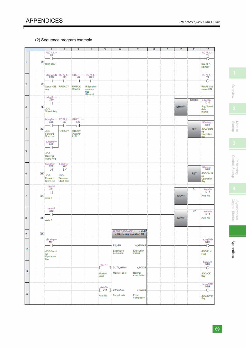
1
Overview
2
Module
Startup
3
Positioning
Control S
tartup
4
Synchronous
Control S
tartup
Appendices
APPENDICES
69
RD77MS Quick Start Guide
(2) Sequence program example
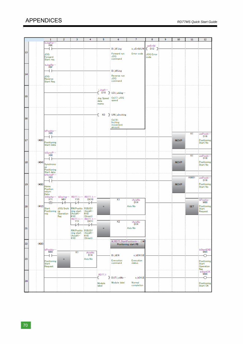
APPENDICES
70
RD77MS Quick Start Guide
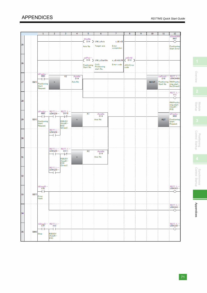
1
Overview
2
Module
Startup
3
Positioning
Control S
tartup
4
Synchronous
Control S
tartup
Appendices
APPENDICES
71
RD77MS Quick Start Guide
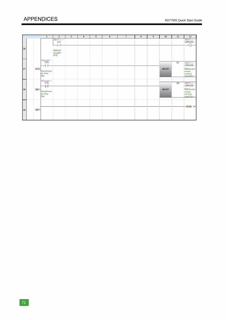
APPENDICES
72
RD77MS Quick Start Guide

Country/Region Sales officeUSA Mitsubishi Electric Automation, Inc.
500 Corporate Woods Parkway, Vernon Hills, IL 60061, U.S.A.Mexico Mitsubishi Electric Automation, Inc. Mexico Branch
Mariano Escobedo #69, Col.Zona Industrial, Tlalnepantla Edo. Mexico, C.P.54030Brazil Mitsubishi Electric do Brasil Comercio e Servicos Ltda.
Rua Jussara, 1750- Bloco B Anexo, Jardim Santa Cecilia, CEP 06465-070, Barueri - SP, BrasilGermany Mitsubishi Electric Europe B.V. German Branch
Gothaer Strasse 8, 40880 Ratingen, GermanyUK Mitsubishi Electric Europe B.V. UK Branch
Travellers Lane, UK-Hatfield, Hertfordshire, AL10 8XB, U.K.Italy Mitsubishi Electric Europe B.V. Italian Branch
Centro Direzionale Colleoni - Palazzo Sirio, Viale Colleoni 7, 20864 Agrate Brianza (Milano), Italy
Spain Mitsubishi Electric Europe B.V. Spanish BranchCarretera de Rubi, 76-80-Apdo. 420, 08190 Sant Cugat del Valles (Barcelona), Spain
France Mitsubishi Electric Europe B.V. French Branch25, Boulevard des Bouvets, 92741 Nanterre Cedex, France
Czech Republic Mitsubishi Electric Europe B.V. Czech BranchAvenir Business Park, Radlicka 751/113e, 158 00 Praha 5, Czech Republic
Poland Mitsubishi Electric Europe B.V. Polish Branchul. Krakowska 50, 32-083 Balice, Poland
Russia Mitsubishi Electric (Russia) LLC St. Petersburg BranchPiskarevsky pr. 2, bld 2, lit “Sch”, BC “Benua”, office 720; 195027 St. Petersburg, Russia
Sweden Mitsubishi Electric Europe B.V. (Scandinavia) Fjelievagen 8, SE-22736 Lund, Sweden
Turkey Mitsubishi Electric Turkey A.S. Umraniye BranchSerifali Mahallesi Nutuk Sokak No:5, TR-34775 Umraniye / Istanbul, Turkey
UAE Mitsubishi Electric Europe B.V. Dubai Branch Dubai Silicon Oasis, P.O.BOX 341241, Dubai, U.A.E.
South Africa ADROIT TECHNOLOGIES20 Waterford Office Park, 189 Witkoppen Road, Fourways, South Africa
China Mitsubishi Electric Automation (China) Ltd.Mitsubishi Electric Automation Center, No.1386 Hongqiao Road, Shanghai, China
Taiwan SETSUYO ENTERPRISE CO., LTD.6F, No.105, Wugong 3rd Road, Wugu District, New Taipei City 24889, Taiwan
Korea Mitsubishi Electric Automation Korea Co., Ltd. 7F-9F, Gangseo Hangang Xi-tower A, 401, Yangcheon-ro, Gangseo-Gu, Seoul 07528, Korea
Singapore Mitsubishi Electric Asia Pte. Ltd.307 Alexandra Road, Mitsubishi Electric Building, Singapore 159943
Thailand Mitsubishi Electric Factory Automation (Thailand) Co., Ltd.12th Floor, SV.City Building, Office Tower 1, No. 896/19 and 20 Rama 3 Road, Kwaeng Bangpongpang, Khet Yannawa, Bangkok 10120, Thailand
Indonesia PT. Mitsubishi Electric IndonesiaGedung Jaya 11th Floor, JL. MH. Thamrin No.12, Jakarta Pusat 10340, Indonesia
Vietnam Mitsubishi Electric Vietnam Company Limited Unit 01-04, 10th Floor, Vincom Center, 72 Le Thanh Ton Street, District 1, Ho Chi Minh City, Vietnam
India Mitsubishi Electric India Pvt. Ltd. Pune BranchEmerald House, EL-3, J Block, M.I.D.C., Bhosari, Pune - 411026, Maharashtra, India
Australia Mitsubishi Electric Australia Pty. Ltd.348 Victoria Road, P.O. Box 11, Rydalmere, N.S.W 2116, Australia
Tel/FaxTel : +1-847-478-2100Fax : +1-847-478-2253Tel : +52-55-3067-7500Fax : –Tel : +55-11-4689-3000Fax : +55-11-4689-3016Tel : +49-2102-486-0Fax : +49-2102-486-1120Tel : +44-1707-28-8780Fax : +44-1707-27-8695Tel : +39-039-60531Fax : +39-039-6053-312
Tel : +34-935-65-3131Fax : +34-935-89-1579Tel : +33-1-55-68-55-68Fax : +33-1-55-68-57-57Tel : +420-251-551-470Fax : +420-251-551-471Tel : +48-12-347-65-00Fax : +48-12-630-47-01Tel : +7-812-633-3497Fax : +7-812-633-3499
Tel : +46-8-625-10-00Fax : +46-46-39-70-18Tel : +90-216-526-3990 Fax : +90-216-526-3995Tel : +971-4-3724716 Fax : +971-4-3724721 Tel : +27-11-658-8100Fax : +27-11-658-8101Tel : +86-21-2322-3030Fax : +86-21-2322-3000Tel : +886-2-2299-2499Fax : +886-2-2299-2509Tel : +82-2-3660-9510Fax : +82-2-3664-8372/8335Tel : +65-6473-2308Fax : +65-6476-7439Tel : +66-2682-6522 to 6531Fax : +66-2682-6020
Tel : +62-21-3192-6461Fax : +62-21-3192-3942Tel : +84-8-3910-5945Fax : +84-8-3910-5947
Tel : +91-20-2710-2000Fax : +91-20-2710-2100Tel : +61-2-9684-7777Fax : +61-2-9684-7245
New publication, effective September 2015.Specifications are subject to change without notice.L(NA)03119-A 1509[IP]
Mitsubishi Electric Corporation Nagoya Works is a factory certified for ISO 14001 (standards for environmental managementsystems) and ISO 9001 (standards for quality assurance management systems).
Mitsubishi Servo System Controllers Quick Start Guide
Recommended