Tallahassee, FL, November 5-6, 2015
Lessons Learned from PHIL Experiments with Power Converters and Fault Current
Limiters
3rd Annual International Workshop on Grid Simulator Testing
of Energy Systems and Wind Turbine Power Trains
J. Langston, M. Steurer, K. Schoder Center for Advanced Power Systems
Florida State University

Overview
I. PHIL II. Lessons Learned
I. Stability II. Engagement of PHIL Interfaces III. Accuracy IV. Flexibility of PHIL Interfaces V. Protection of PHIL Experiments VI. Other Points
III. Conclusion
Nov. 5-6, 2015 Grid Simulator Testing Workshop 2

HIL Simulation Approach
Nov. 5-6, 2015 Grid Simulator Testing Workshop 3
• A device under test (DUT) is interfaced to a simulated environment through HIL interfaces to a real-time simulation model
• Allows – DUT to be exercised in a wide range of
potentially realistic environments – Execution of extreme conditions within
controlled lab environment – DUT to be tested with systems not yet
constructed – DUT to be exercised to extremes of
interface specifications including controlled transients
• Controller HIL (CHIL) – HIL Interfaces use control level (low
voltage) signals for I/O • Power HIL (PHIL)
– Power amplifiers and/or actuators are used for interfacing
– Power flow over PHIL interface
Interface
Algorithm
G Interface
AlgorithmMRG
A
B
C
DUT
A
B
C
Amplifier Dynamometer
References
andFeedback
References
andFeedback
Real Time Simulation
SimulatedDUT
GMRG
DUTController
ControlSignalsSimulated
VabcandIabc
SimulatedTand
Real Time Simulation

Challenges Associated with HIL Simulation
Nov. 5-6, 2015 Grid Simulator Testing Workshop 4
• Restrictions of real-time simulation – Typically fixed time-step size simulations with minimum achievable time-step size – Limitations on the size and complexity of simulated systems due to finite
computational resources • Limitations of amplifiers and actuators (max power, torque, speed, etc.) • Assessment of the impact of HIL Interfaces (particularly PHIL) • Accuracy of models used for surroundings
– Common issue with modeling and simulation activities, in general – establishing confidence in the models.
– Synergy between model verification and validation (V&V) and HIL simulation
DUT
DUT
Controller
Amplif ier
Amplif ier
Controller
PHILInterface
Controls
Interface
ComponentROS
RealTime
Simulator
PHIL
Interface
• Non-ideal interfaces – Time delays associated with
I/O, controllers for actuators and amplifiers, etc.
– Limited bandwidth of amplifiers and actuators

Stability of PHIL Experiments
Nov. 5-6, 2015 Grid Simulator Testing Workshop 5
[1] Wei Ren, M. Steurer, and T.L. Baldwin. Improve the stability and the accuracy of power hardware-in-the-loop simulation by selecting appropriate interface algorithms. Industry Applications, IEEE Transactions on, 44(4):1286-1294, July 2008. [2] Alexander Viehweider, Felix Lehfuss, and Georg Lauss. Interface and stability issues for SISO and MIMO power hardware in the loop simulation of distribution networks with photovoltaic generation. International Journal of Renewable Energy Research (IJRER), 2(4):631-639, 2012.
PHIL System [1] Example ROS and DUT
Voltage Type Ideal Transformer Model Interface Algorithm
𝑊𝑊 = −1 + det (𝐼𝐼 + 𝐺𝐺𝑂𝑂𝑂𝑂)
𝐺𝐺𝑂𝑂𝑂𝑂−𝐼𝐼𝐼𝐼𝐼𝐼−𝑉𝑉𝐼𝐼 = −𝑍𝑍𝐴𝐴𝑍𝑍𝐵𝐵
𝑇𝑇𝑚𝑚𝐼𝐼𝑇𝑇𝐴𝐴
𝐺𝐺𝑂𝑂𝑂𝑂−𝐼𝐼𝐼𝐼𝐼𝐼−𝐼𝐼𝐼𝐼 = −𝑍𝑍𝐵𝐵𝑍𝑍𝐴𝐴
𝑇𝑇𝑚𝑚𝑉𝑉𝑇𝑇𝐴𝐴
[2]
ROS DUT+
-

Examples of PHIL Experiments Presenting Challenges in Terms of Stability
Nov. 5-6, 2015 Grid Simulator Testing Workshop 6
Fault Current Limiters
Island Detection Tests for PV Inverters
ROS DUT
PHIL Interface
RLC Load Bank
PV Inverter
ROS DUT
PHIL Interface

Engagement of PHIL Interfaces
Nov. 5-6, 2015 Grid Simulator Testing Workshop 7
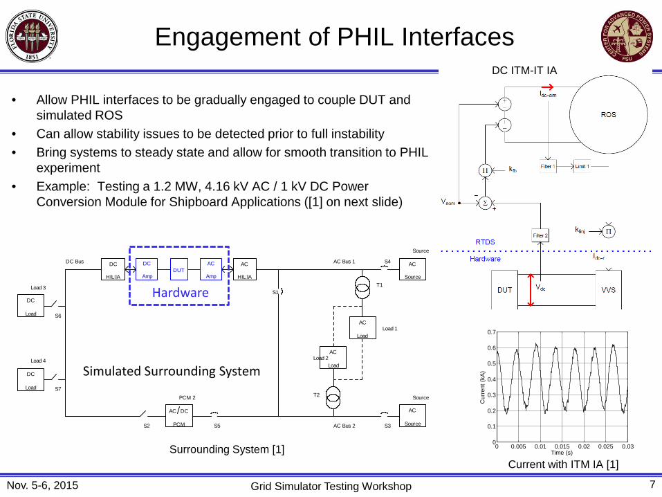
• Allow PHIL interfaces to be gradually engaged to couple DUT and simulated ROS
• Can allow stability issues to be detected prior to full instability • Bring systems to steady state and allow for smooth transition to PHIL
experiment • Example: Testing a 1.2 MW, 4.16 kV AC / 1 kV DC Power
Conversion Module for Shipboard Applications ([1] on next slide)
Surrounding System [1] Current with ITM IA [1]
DC ITM-IT IA

Engagement of PHIL Interfaces
Nov. 5-6, 2015 Grid Simulator Testing Workshop 7
• Allow PHIL interfaces to be gradually engaged to couple DUT and simulated ROS
• Can allow stability issues to be detected prior to full instability • Bring systems to steady state and allow for smooth transition to PHIL
experiment • Example: Testing a 1.2 MW, 4.16 kV AC / 1 kV DC Power
Conversion Module for Shipboard Applications ([1] on next slide)
0 0.005 0.01 0.015 0.02 0.025 0.030
0.1
0.2
0.3
0.4
0.5
0.6
0.7
Time (s)
Cur
rent
(kA
)
Surrounding System [1] Current with ITM IA [1]
DC ITM-IT IA
Engagement of PHIL Interfaces
Nov. 5-6, 2015 Grid Simulator Testing Workshop 7
• Allow PHIL interfaces to be gradually engaged to couple DUT and simulated ROS
• Can allow stability issues to be detected prior to full instability • Bring systems to steady state and allow for smooth transition to PHIL
experiment • Example: Testing a 1.2 MW, 4.16 kV AC / 1 kV DC Power
Conversion Module for Shipboard Applications ([1] on next slide)
0 0.005 0.01 0.015 0.02 0.025 0.030
0.1
0.2
0.3
0.4
0.5
0.6
0.7
Time (s)
Cur
rent
(kA
)
AC
Source
Source
DUTAC
Amp
DC
Amp
AC
HILIA
DC
HILIA
DC
Load
Load 3
DC
Load
Load 4
S4
S6
S7
AC
Source
Source
AC DC
PCM
PCM 2
S2 S3S5
S1
AC
LoadLoad 1
T1
AC
LoadLoad 2
T2
AC Bus 1
AC Bus 2
DC Bus
Hardware
Simulated Surrounding System
Surrounding System [1] Current with ITM IA [1]
DC ITM-IT IA

Engagement of PHIL Interfaces
Nov. 5-6, 2015 Grid Simulator Testing Workshop 7
• Allow PHIL interfaces to be gradually engaged to couple DUT and simulated ROS
• Can allow stability issues to be detected prior to full instability • Bring systems to steady state and allow for smooth transition to PHIL
experiment • Example: Testing a 1.2 MW, 4.16 kV AC / 1 kV DC Power
Conversion Module for Shipboard Applications ([1] on next slide)
0 0.005 0.01 0.015 0.02 0.025 0.030
0.1
0.2
0.3
0.4
0.5
0.6
0.7
Time (s)
Cur
rent
(kA
)
Surrounding System [1] Current with ITM IA [1]
DC ITM-IT IA

Engagement of PHIL Interfaces
Nov. 5-6, 2015 Grid Simulator Testing Workshop 8
• Example: Testing a 1.2 MW, 4.16 kV AC / 1 kV DC Power Conversion Module for Shipboard Applications [1]
• Employed current-type Damping Impedance Method (DIM) IA [2]
0 0.005 0.01 0.015 0.02 0.025 0.030
0.1
0.2
0.3
0.4
0.5
0.6
0.7
Time (s)
Cur
rent
(kA
)
[1] J. Langston, F. Bogdan, J. Hauer, K. Schoder, M. Steurer, D. Dalessandro, T. Fikse, J. Cherry, and S. Gonstead, “Megawatt-scale power hardware-in-the-loop simulation testing of a power conversion module for naval applications," Electric Ship Technologies Symposium (ESTS), 2015 IEEE, pp.268,275, 21-24 June 2015. [2] Richard Mack Mersenski. Evaluation of a new power-hardware-in-the-loop (PHIL) interface algorithm for current controlled amplifiers. Master's thesis, University of South Carolina, 2011.
DC DIM-IT IA Current with DIM IA [1]

Engagement of PHIL Interfaces
Nov. 5-6, 2015 Grid Simulator Testing Workshop 9
• Example: PHIL Testing of Air Core Superconducting FCL [1] • Used Modified DIM IA [2] • Initialized damping impedance to known pre-quench impedance • Used a few cycles of pre-fault, load current to allow the
impedance to be estimated and all feedback of the IA engaged
[1] Naeckel, O.; Langston, J.; Steurer, M.; Fleming, F.; Paran, S.; Edrington, C.; Noe, M., "Power Hardware-in-the-Loop Testing of an Air Coil Superconducting Fault Current Limiter Demonstrator," Applied Superconductivity, IEEE Transactions on , vol.25, no.3, pp.1,7, June 2015. [2] Sanaz Paran and CS Edrington. Improved power hardware in the loop interface methods via impedance matching. In Electric Ship Technologies Symposium (ESTS), 2013 IEEE, pages 342-346. IEEE, 2013.
PHIL Setup and ROS [1] Voltage and DUT Impedance [1]

Accuracy
Nov. 5-6, 2015 Grid Simulator Testing Workshop 10
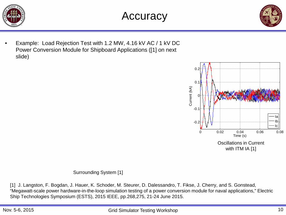
• Example: Load Rejection Test with 1.2 MW, 4.16 kV AC / 1 kV DC Power Conversion Module for Shipboard Applications ([1] on next slide)
Surrounding System [1]
[1] J. Langston, F. Bogdan, J. Hauer, K. Schoder, M. Steurer, D. Dalessandro, T. Fikse, J. Cherry, and S. Gonstead, “Megawatt-scale power hardware-in-the-loop simulation testing of a power conversion module for naval applications," Electric Ship Technologies Symposium (ESTS), 2015 IEEE, pp.268,275, 21-24 June 2015.
Oscillations in Current with ITM IA [1]

Accuracy
Nov. 5-6, 2015 Grid Simulator Testing Workshop 10
• Example: Load Rejection Test with 1.2 MW, 4.16 kV AC / 1 kV DC Power Conversion Module for Shipboard Applications ([1] on next slide)
AC
Source
Source
DUTAC
Amp
DC
Amp
AC
HILIA
DC
HILIA
DC
Load
Load 3
DC
Load
Load 4
S4
S6
S7
AC
Source
Source
AC DC
PCM
PCM 2
S2 S3S5
S1
AC
LoadLoad 1
T1
AC
LoadLoad 2
T2
AC Bus 1
AC Bus 2
DC Bus
Hardware
Simulated Surrounding System
Surrounding System [1]
[1] J. Langston, F. Bogdan, J. Hauer, K. Schoder, M. Steurer, D. Dalessandro, T. Fikse, J. Cherry, and S. Gonstead, “Megawatt-scale power hardware-in-the-loop simulation testing of a power conversion module for naval applications," Electric Ship Technologies Symposium (ESTS), 2015 IEEE, pp.268,275, 21-24 June 2015.
Oscillations in Current with ITM IA [1]

Accuracy
Nov. 5-6, 2015 Grid Simulator Testing Workshop 10
• Example: Load Rejection Test with 1.2 MW, 4.16 kV AC / 1 kV DC Power Conversion Module for Shipboard Applications ([1] on next slide)
Surrounding System [1]
[1] J. Langston, F. Bogdan, J. Hauer, K. Schoder, M. Steurer, D. Dalessandro, T. Fikse, J. Cherry, and S. Gonstead, “Megawatt-scale power hardware-in-the-loop simulation testing of a power conversion module for naval applications," Electric Ship Technologies Symposium (ESTS), 2015 IEEE, pp.268,275, 21-24 June 2015.
Oscillations in Current with ITM IA [1]
Accuracy
Nov. 5-6, 2015 Grid Simulator Testing Workshop 10
• Example: Load Rejection Test with 1.2 MW, 4.16 kV AC / 1 kV DC Power Conversion Module for Shipboard Applications ([1] on next slide)
Surrounding System [1]
[1] J. Langston, F. Bogdan, J. Hauer, K. Schoder, M. Steurer, D. Dalessandro, T. Fikse, J. Cherry, and S. Gonstead, “Megawatt-scale power hardware-in-the-loop simulation testing of a power conversion module for naval applications," Electric Ship Technologies Symposium (ESTS), 2015 IEEE, pp.268,275, 21-24 June 2015.
0 0.02 0.04 0.06 0.08
-0.2
-0.1
0
0.1
0.2
Time (s)
Cur
rent
(kA
)
IaIbIc
Oscillations in Current with ITM IA [1]

Accuracy
Nov. 5-6, 2015 Grid Simulator Testing Workshop 11
• Example: Load Rejection Test with 1.2 MW, 4.16 kV AC / 1 kV DC Power Conversion Module for Shipboard Applications ([1] on next slide)
Currents Using DIM IA (Lower Damping Impedance) [1]
[1] J. Langston, F. Bogdan, J. Hauer, K. Schoder, M. Steurer, D. Dalessandro, T. Fikse, J. Cherry, and S. Gonstead, “Megawatt-scale power hardware-in-the-loop simulation testing of a power conversion module for naval applications," Electric Ship Technologies Symposium (ESTS), 2015 IEEE, pp.268,275, 21-24 June 2015.
Currents Using DIM IA (Higher Damping Impedance) [1]

Protection Systems
Nov. 5-6, 2015 Grid Simulator Testing Workshop 12
• Important to protect the DUT • Gracefully shut down the experiment if a problem is encountered • Take (only) appropriate actions in response to detected problems • Example: Testing 1.2 MW, 15,000 RPM High Speed Generator [1]
[1] J. Langston, M. Steurer, K. Schoder, J. Hauer, F. Bogdan, I. Leonard, T. Chiocchio, M. Sloderbeck, A. Farrell, J. Vaidya, and K. Yost, “Megawatt Scale Hardware-in-the-Loop Testing of a High Speed Generator,” Proc. 2012 ASNE Day, Arlington, VA, February 9-10, 2012.
Test Setup [1]
• Protection Elements – Over-voltage – Over-current – Over-speed – Over-torque
• Protection Actions – Open closed-loop controls – Open excitation switch – Ramp VVS (load) current to zero – Ramp dynamometer speed to zero – Step dynamometer speed reference to zero

Protection Systems
Nov. 5-6, 2015 Grid Simulator Testing Workshop 13
• Methods to detect the onset of instability – Frequency – Voltage/current distortion – Time-based – Others
• Example: Anti-Islanding Tests of PV Inverters using PHIL [1]
[1] M. Steurer, K. Schoder, J. Langston, J. Hauer, and B. Mather, “Progress on Power Hardware-in-the-Loop Based Anti-Islanding Testing of PV Converters,” Presentation at the Second International Workshop on Grid Simulator Testing of Wind Turbine Drivetrains, September 17-18, 2014, North Charleston, South Carolina, USA.
Stable Case [1]
-50 0 50 100-30
-20
-10
0
10
20
3057 ms40 ms
42 ms
time (ms)
I a (A)
Capture 562: 8 kW, Qf=1, ITM, Rwye, 1/10
mea (C)modelmea (M)
-10 0 10 20 30 40 50 60-6
-4
-2
0
2
4
6
850 ms33 ms
54 ms
time (ms)
I a (A)
Capture 599: 3 kW, Qf=2, ITM, Rwye
mea (C)modelmea (M)
Marginally Stable Case [1]
SwitchPVConverter
AC-Source
Load BankR-L-C
DC-Source
Anti-Island Test Setup [1]

Other Points
Nov. 5-6, 2015 Grid Simulator Testing Workshop 14
• Simulation Mode • Information Collection
– Capture Reference Signals
– Collect Trending Information Including Settings
• Minimize Surrounding System
• Detailed Checklists and Procedures
• Attention to Detail Surrounding System [1]
[1] J. Langston, F. Bogdan, J. Hauer, K. Schoder, M. Steurer, D. Dalessandro, T. Fikse, J. Cherry, and S. Gonstead, “Megawatt-scale power hardware-in-the-loop simulation testing of a power conversion module for naval applications," Electric Ship Technologies Symposium (ESTS), 2015 IEEE, pp.268,275, 21-24 June 2015.

Other Points
Nov. 5-6, 2015 Grid Simulator Testing Workshop 14
• Simulation Mode • Information Collection
– Capture Reference Signals
– Collect Trending Information Including Settings
• Minimize Surrounding System
• Detailed Checklists and Procedures
• Attention to Detail
AC
Source
Source
DUTAC
Amp
DC
Amp
AC
HILIA
DC
HILIA
DC
Load
Load 3
DC
Load
Load 4
S4
S6
S7
AC
Source
Source
AC DC
PCM
PCM 2
S2 S3S5
S1
AC
LoadLoad 1
T1
AC
LoadLoad 2
T2
AC Bus 1
AC Bus 2
DC Bus
Hardware
Simulated Surrounding System
Surrounding System [1]
[1] J. Langston, F. Bogdan, J. Hauer, K. Schoder, M. Steurer, D. Dalessandro, T. Fikse, J. Cherry, and S. Gonstead, “Megawatt-scale power hardware-in-the-loop simulation testing of a power conversion module for naval applications," Electric Ship Technologies Symposium (ESTS), 2015 IEEE, pp.268,275, 21-24 June 2015.
Other Points
Nov. 5-6, 2015 Grid Simulator Testing Workshop 14
• Simulation Mode • Information Collection
– Capture Reference Signals
– Collect Trending Information Including Settings
• Minimize Surrounding System
• Detailed Checklists and Procedures
• Attention to Detail Surrounding System [1]
[1] J. Langston, F. Bogdan, J. Hauer, K. Schoder, M. Steurer, D. Dalessandro, T. Fikse, J. Cherry, and S. Gonstead, “Megawatt-scale power hardware-in-the-loop simulation testing of a power conversion module for naval applications," Electric Ship Technologies Symposium (ESTS), 2015 IEEE, pp.268,275, 21-24 June 2015.
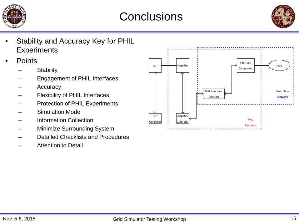
Conclusions
Nov. 5-6, 2015 Grid Simulator Testing Workshop 15
• Stability and Accuracy Key for PHIL Experiments
• Points – Stability – Engagement of PHIL Interfaces – Accuracy – Flexibility of PHIL Interfaces – Protection of PHIL Experiments – Simulation Mode – Information Collection – Minimize Surrounding System – Detailed Checklists and Procedures – Attention to Detail
DUT
DUT
Controller
Amplif ier
Amplif ier
Controller
PHILInterface
Controls
Interface
ComponentROS
RealTime
Simulator
PHIL
Interface
Recommended