Lecture 12 (Requirements Engineering)
Dr. Sheela Ramanna
Applied Computer Science
University of Winnipeg
Chapters 17 and 18

Related to Product and Project Competencies

Managing Requirements
Why
Too many requirements
What
Systematic way of handling requirements
How
Requirements Engineering
The Activities of the Analysis Phase

Types of SW Requirements
Functional
Specify what the software has to do (functions that need to be implemented)
Non-functional
Quality requirements such as performance, reliability, usability (how well the functions perform)
Other
Legal issues, standards issues and so on

Requirements Engineering
Project moves from recognition and definition of the problem domain to a solution domain A Bridge to Design and Construction
Foundation of the software product Cost of missed or incorrect requirement Relates primarily to product competency
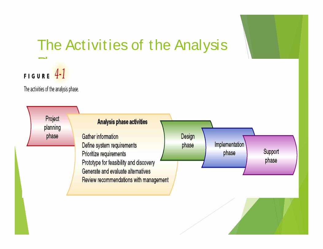
Requirements Engineering Steps
1. Requirements Inception2. Requirements Elicitation- understanding what
the customers want3. Requirements analysis (elaboration) and
negotiation-analyzing need and negotiating a reasonable solution
4. Requirements specification- specifying the solution unambiguously (Document)
5. Requirements validation6. Requirements Management

2. Requirements Elicitation Methods
Interviewing Brainstorming (creative thinking) Questionnaire Joint-Application Development (JAD) Use-case scenarios QFD – Quality Function Deployment
Identify affected communities Create high-level requirements Assign a value to each requirement
indicating degree of importance to the customer
“The hardest single part of building a software system is deciding precisely what to build”– Fred Brooks

Requirements Elicitation
Problems of scope Establishing system boundaries
Problems of understanding What the customers want
Problems of Volatility Changing requirements (over time)

3. Requirements Elaboration
Also known as Analysis Modeling Defines (using a standard
modeling technique) the data(information), functional and behavioral domain of the system

4. Requirements Specification
Written document, formal mathematical model, set of graphical models, a prototype, use-case scenarios..
Final Work Product of Requirements Engineering
System Requirements Specification (SRS) or System Study Report (SSR)

Software Requirements Document
Industry 4901 CourseSoftware Requirements Document (SRS)
System Study Report (SSR)
Both documents are a result of the requirements gathering (or analysis phases)

SRS Goals
A well-designed, well-written SRS accomplishes four major goals: Provides feedback to the customer It decomposes the problem into component
parts It serves as an input to the design specification It serves as a product validation check.

Topics addressed in a typical SRS Interfaces Functional Capabilities Performance Levels Data Structures/Elements Safety Reliability Security/Privacy Quality Constraints and Limitations

How does one create an SRS?
1. A template2. A method for identifying requirements and
linking sources3. Business operation rules4. A traceability matrix

1. Example: Industry Template1. Introduction 1.1 Purpose 1.2 Document conventions 1.3 Intended audience 1.4 Additional information 1.5 Contact information/SRS team members 1.6 References
2. Overall Description 2.1 Product perspective 2.2 Product functions 2.3 User classes and characteristics 2.4 Operating environment 2.5 User environment 2.6 Design/implementation constraints 2.7 Assumptions and dependencies
3. External Interface Requirements 3.1 User interfaces 3.2 Hardware interfaces 3.3 Software interfaces 3.4 Communication protocols and interfaces
4. System Features 4.1 System feature A 4.1.1 Description and priority 4.1.2 Action/result 4.1.3 Functional requirements 4.2 System feature B
5. Other Nonfunctional Requirements 5.1 Performance requirements 5.2 Safety requirements 5.3 Security requirements 5.4 Software quality attributes 5.5 Project documentation 5.6 User documentation
6. Other Requirements Appendix A: Terminology/Glossary/Definitions list Appendix B: To be determined
1. SRS Table of Contents or Template
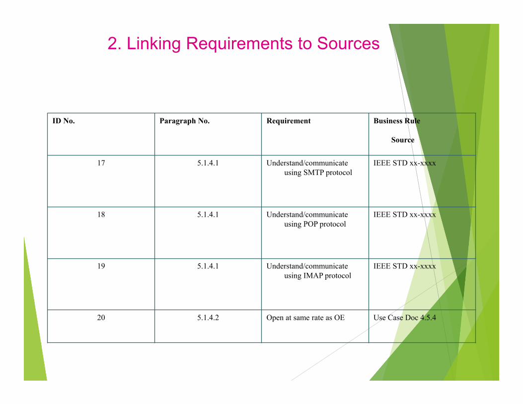
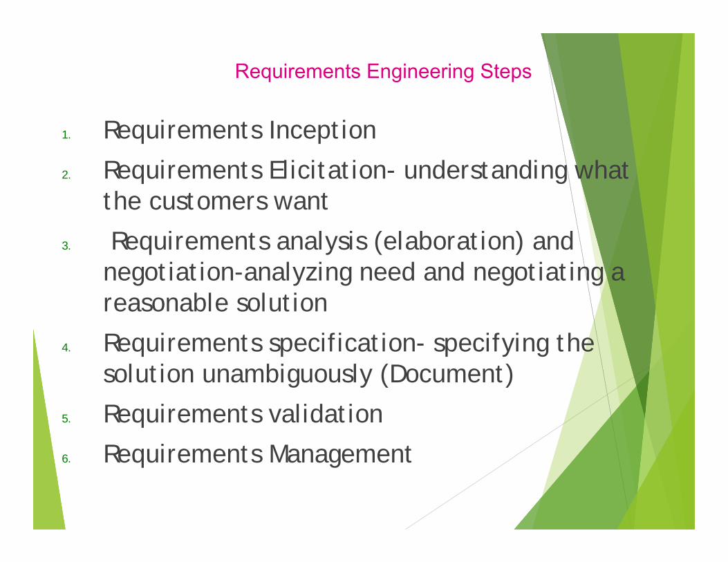
2. Linking Requirements to Sources
ID No. Paragraph No. Requirement Business Rule
Source
17 5.1.4.1 Understand/communicate using SMTP protocol
IEEE STD xx-xxxx
18 5.1.4.1 Understand/communicate using POP protocol
IEEE STD xx-xxxx
19 5.1.4.1 Understand/communicate using IMAP protocol
IEEE STD xx-xxxx
20 5.1.4.2 Open at same rate as OE Use Case Doc 4.5.4

Characteristics of a good SRS
Correctness Unambiguousness Completeness Consistency Ranking for importance Verifiability Modifiability Traceability
http://www.techwrl.com/techwhirl/magazine/writing/softwarerequirementspecs.html

Characteristics of a good SRS
Correctness An SRS is correct only if every requirement
stated therein is one that the SW shall meet Unambiguousness
If every requirement has only one interpretation
Representation tools/methodologies such as UML should be used rather than natural language
Characteristics of a good SRS
Completeness All significant requirements are included Full labels and references to all figures/tables No TBD (To be determined) labels
Consistency logical conflict between actions Conflict amongst characteristics Two or more requirements may describe the
same object but use different terms This problem stems from terminology used
in different domains ( health care, military..)

Characteristics of a good SRS Ranking for importance
Essential Conditional Optional
Verifiable If there exists some finite cost-effective
process with which a person or machine can check if the product meets the requirement
Modifiable SRS has a easy-to-use organization with a TOC,
index and cross-referencing Traceability (using a matrix to perform forward
and backward traceability)

Requirements Traceability Matrix (Simple)
DesignReqID Screen 1.1 DB Design Report 2.1 Report 2.2
1.1 Yes1.2 Yes Yes1.31.4 Yes2.12.22.32.42.5

Example 1The example below shows the links that are to be maintained. To demonstrate bi-directional traceability evidence of sorting (and use) by each column is to be captured.
Unique Requirement ID
Requirement Description Design Reference
Module / Configured Item Reference
Release Reference
Test Script Name/Step Number Reference
(Original source: NASA PAL Link)
Instructions
The above table should be created in a spreadsheet or database such that it may be easily sorted by each column to achieve bi-directional traceability between columns. The unique identifiers for items should be assigned in a hierarchical outline form such that the lower level (more detailed) items can have their lineage traced.
Unique Requirement ID The Unique Requirement ID / System Requirement Statement where the requirement is referenced, and/or the unique ID for decomposed requirements
Requirement Description Enter the description of the requirement (e.g., Change Request description).
Design Reference Enter the paragraph number where the CR is referenced in the design documentation
Module / Configured Item Reference Enter the unique identifier of the software module or configured item where the design is realized.
Release Reference Enter the release/build version number where the requirement is fulfilled
Test Script Name/Step Number Reference Enter the test script name/step number where the requirement is referenced (e.g., Step 1)

Legend:
1.COTS CSC (Computer Software Component)
1.1 User I/F CSC
1.3 OPSLAN I/F CSC
2.0 DAQ I/F CSC
2.1 Data Format/Storage CSC
SRS Requirement Design Component(s) (CSC’s)
3.2.1.1 1.0, 1.1
3.2.1.2 1.0, 1.1
3.2.1.3 1.0, 1.1
3.2.1.4 1.0, 1.1
Example: Partial RTM

Requirements Validation Checklist
Are requirements stated clearly Is the source of the requirement identified Is this requirement really necessary or an add-on
feature Is this requirement testable Is this requirement traceable Is this requirement bounded What other requirements are related to this
requirement Does this requirement conflict with other
requirements

Requirements Management Planning
Requirements identification A change management process Traceability policy CASE tool support (spreadsheets, simple
DB systems)

System Study Report
• It is a deliverable that is produced at the end of the Analysis Phase as a part of the Applied CS Lifecycle
• Also called System Study Report (SSR)
• Documents all the work done starting from the initiation phase to the end of analysis phase
• A Technical Meeting is held at the end of the analysis phase to discuss the SSR
• Scope of the project
• Risks and Controls
• Change Control
• Plans (Implementation and Training Plans)
• Technical Issues

Table of Contents
1.0 Introduction
1.1 Project Initiation
1.2 User Environment
1.3 Description of the Current System
1.4 Shortcomings and Benefits of the Current System
2.0 Proposed System
2.1 Objectives of the Proposed System
2.2 Benefits of the Proposed System
2.3 Scope of the Proposed System
2.4 Statement of User Requirements (Ranking)

Table of Contents 3.0 System Architecture
3.1 Software Architecture Options
3.2 Hardware Architecture Options
4.0 Advisability Study 4.1 Evaluation Criteria
4.1.1 Software
4.1.2 Hardware
4.1.3 Software Tools
4.2 Evaluation
4.2.1 Software
4.2.2 Hardware
4.2.3 Software Tools
4.3 Recommendation
4.3.1 Software
4.3.2 Hardware
4.3.3 Software Tools

Table of Contents 5.0 General Design
5.1 Description
5.2 Context-level Process Model
5.3 Preliminary Data Model
5.4 Description of Screens/Reports
5.5 Testing Plans
5.6 Conversion Plans
5.7 Training Plans
5.8 Implementation Plan
5.9 Risk and Control Issues
5.10 User and Technical Manuals

Table of Contents 6.0 Project Management
6.1 Assumptions
6.2 Change Control Management
6.3 Maintenance Issues
6.4 Project Plan
7.0 Appendix
A. Process Model: DFDs for current system (if necessary)
B. Process Model: DFDs for proposed system
C. Preliminary Data Model: ERD
D. Preliminary Data Dictionary
E. Preliminary Screen Designs
F. Preliminary Report Designs
G. Work Request
H. Change Control Form

System Study Report The System Study Report (SSR) is submitted for
approval by each team to its IS Director prior to the system study review.
Upon approval, the team must distribute copies of the SSR to all faculty members of the Applied CS Department as well as to the end-user(s).
The narrative part (not including design documents) of the report should not exceed 50 pages in length.
The General Design Diagrams for the system must follow the notation described in the section 8.0 of this document.

Requirements – Validation (Methods)
Requirements reviews (formal technical review) Prototyping Test-case generation Automated consistency analysis (when there are
too many requirements)
In 4901, System Study Review is a formal Technical Review held in November
Recommended