1
12/03/15
Computer Graphics
Lecture 10
Global Illumination 1: Ray Tracing and Radiosity
Taku Komura
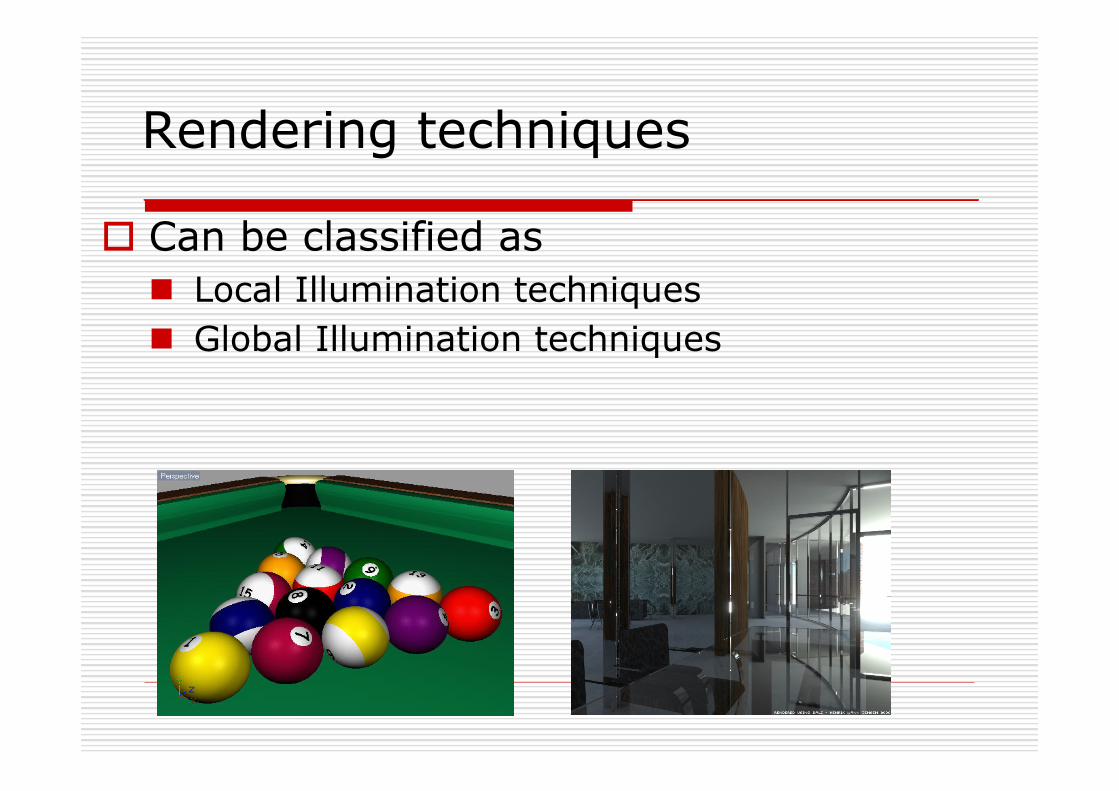
Rendering techniques
o Can be classified as n Local Illumination techniques n Global Illumination techniques
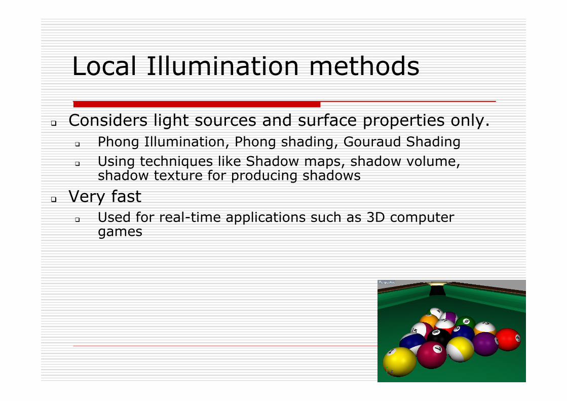
Local Illumination methods q Considers light sources and surface properties only.
q Phong Illumination, Phong shading, Gouraud Shading q Using techniques like Shadow maps, shadow volume,
shadow texture for producing shadows q Very fast
q Used for real-time applications such as 3D computer games
4
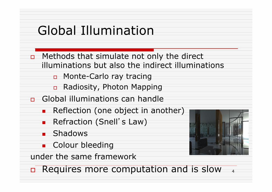
Global Illumination
o Methods that simulate not only the direct illuminations but also the indirect illuminations
o Monte-Carlo ray tracing o Radiosity, Photon Mapping
o Global illuminations can handle n Reflection (one object in another) n Refraction (Snell’s Law) n Shadows n Colour bleeding
under the same framework o Requires more computation and is slow
5
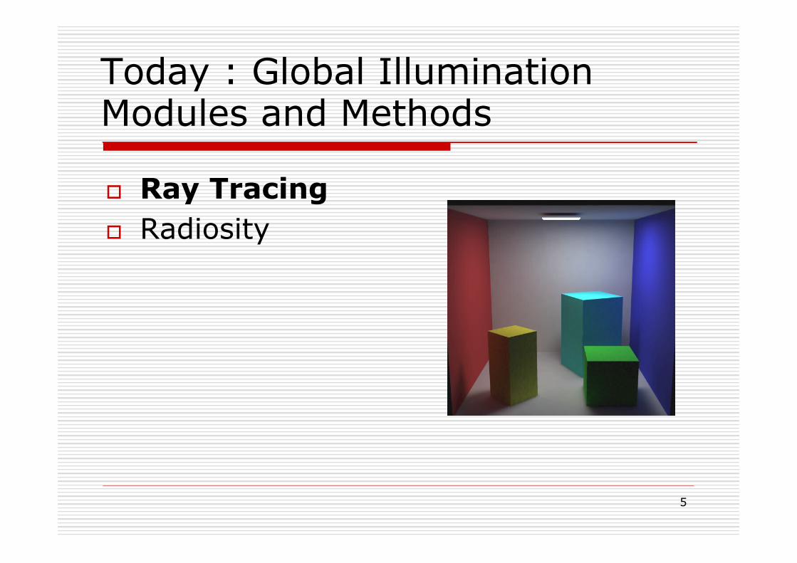
Today : Global Illumination Modules and Methods
o Ray Tracing o Radiosity
6
12/03/15
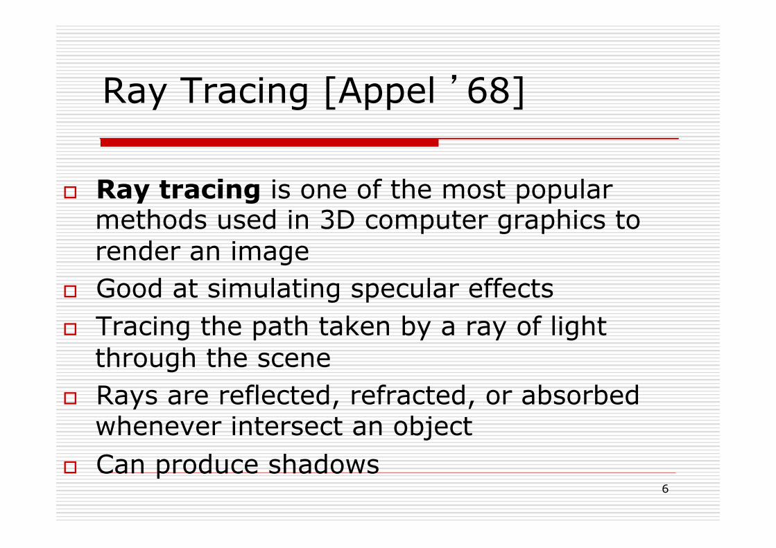
Ray Tracing [Appel ’68]
o Ray tracing is one of the most popular methods used in 3D computer graphics to render an image
o Good at simulating specular effects o Tracing the path taken by a ray of light
through the scene o Rays are reflected, refracted, or absorbed
whenever intersect an object o Can produce shadows
7
12/03/15
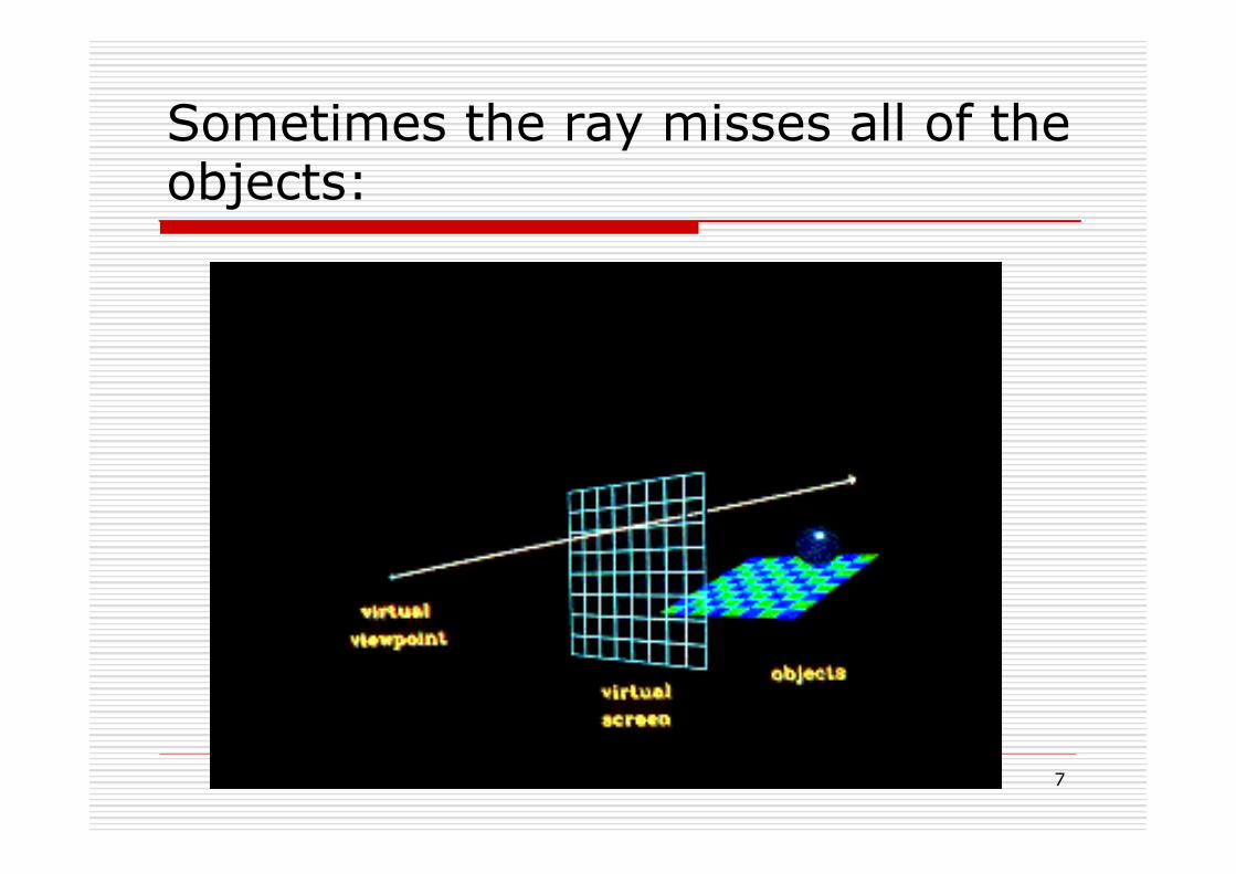
Sometimes the ray misses all of the objects:
8
12/03/15
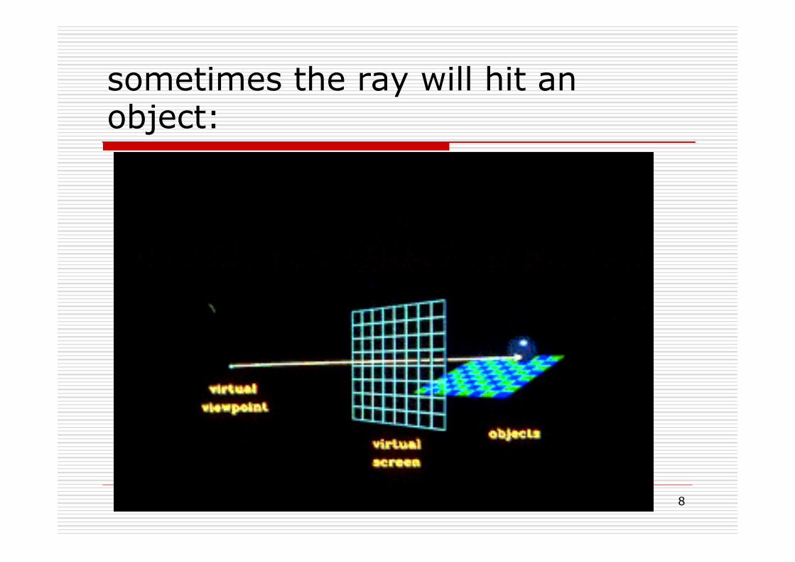
sometimes the ray will hit an object:
9
12/03/15
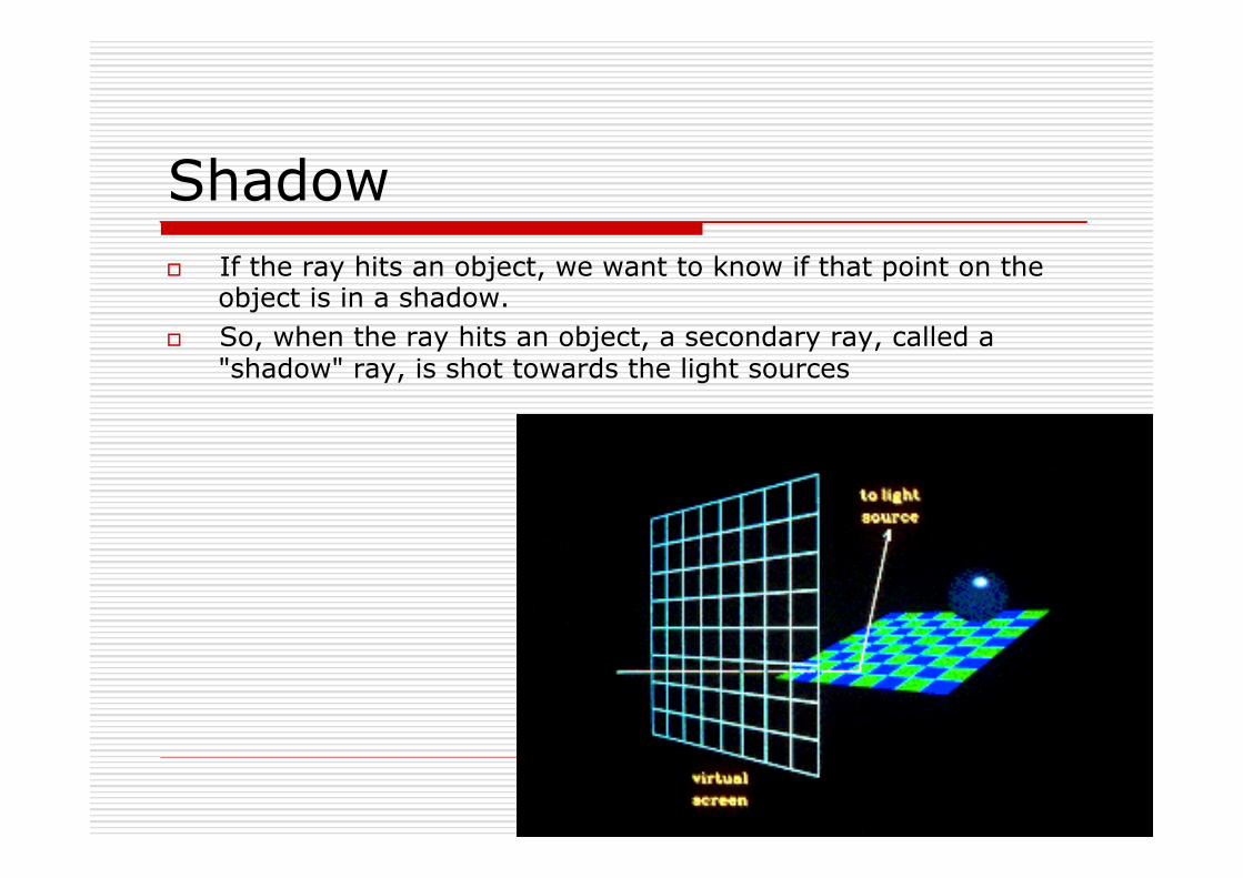
Shadow o If the ray hits an object, we want to know if that point on the
object is in a shadow. o So, when the ray hits an object, a secondary ray, called a
"shadow" ray, is shot towards the light sources
10
12/03/15
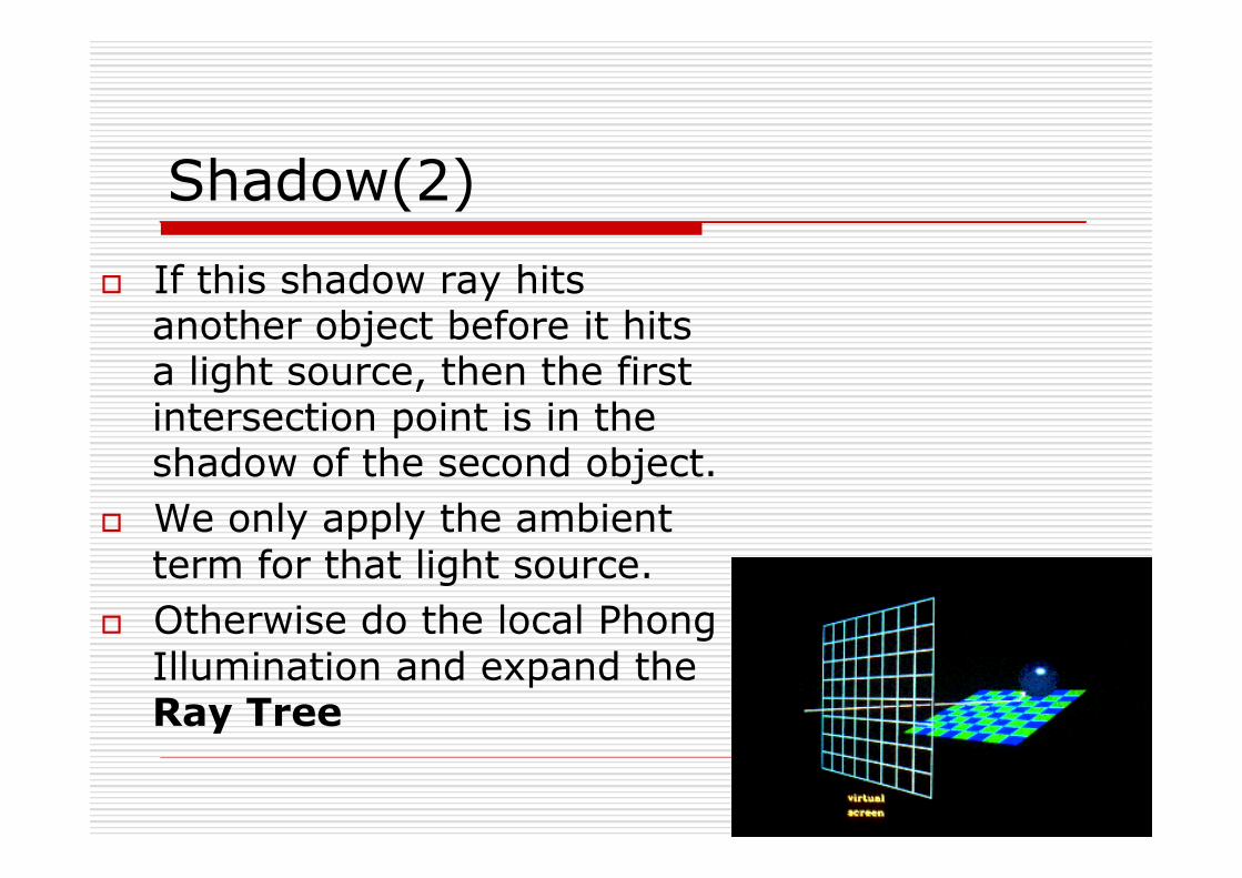
Shadow(2) o If this shadow ray hits
another object before it hits a light source, then the first intersection point is in the shadow of the second object.
o We only apply the ambient term for that light source.
o Otherwise do the local Phong Illumination and expand the Ray Tree

11
12/03/15
Shadow (3) o First Intersection point in the shadow
of the second object

12
12/03/15
Reflected Ray o Also, when a ray
hits an object, a reflected ray is generated which is tested against all of the objects in the scene.
13
12/03/15
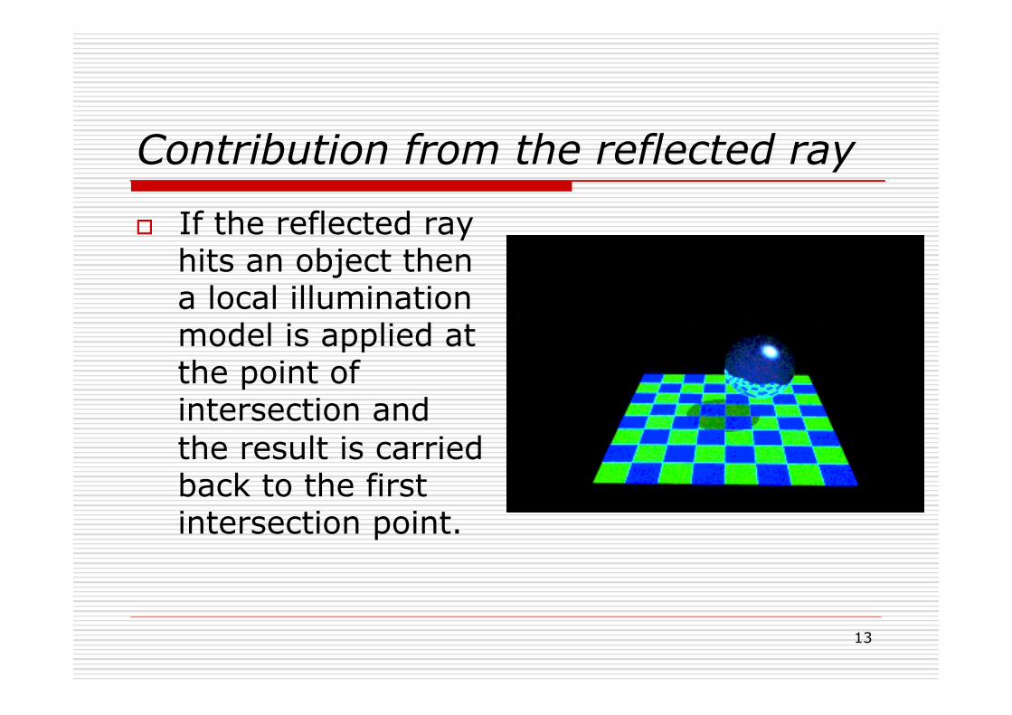
Contribution from the reflected ray
o If the reflected ray hits an object then a local illumination model is applied at the point of intersection and the result is carried back to the first intersection point.

14
12/03/15
Transmitted Ray o If the intersected
object is transparent, then a transmitted ray is generated and tested against all the objects in the scene

15
12/03/15
Contribution from the transmitted ray
o As with the reflected ray, if the transmitted ray hits an object then a local illumination model is applied at the point of intersection and the result is carried back to the first intersection point.
16
12/03/15
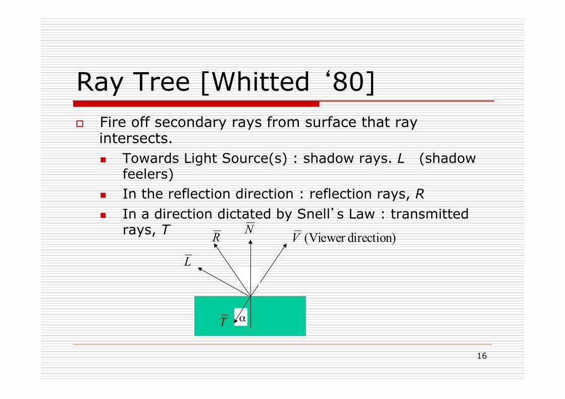
Ray Tree [Whitted ‘80] o Fire off secondary rays from surface that ray
intersects. n Towards Light Source(s) : shadow rays. L (shadow
feelers) n In the reflection direction : reflection rays, R n In a direction dictated by Snell’s Law : transmitted
rays, T
θ
N
Lθ
α
direction)(Viewer VR
T
17
12/03/15
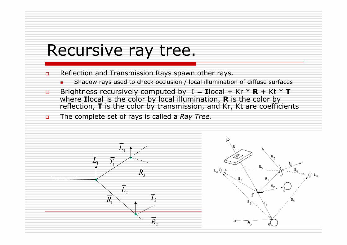
Recursive ray tree. o Reflection and Transmission Rays spawn other rays.
n Shadow rays used to check occlusion / local illumination of diffuse surfaces
o Brightness recursively computed by I = Ilocal + Kr * R + Kt * T where Ilocal is the color by local illumination, R is the color by reflection, T is the color by transmission, and Kr, Kt are coefficients
o The complete set of rays is called a Ray Tree.
Viewpoint
1L
2L
3L
1R
2R
3R1T
2T
Light Source ray determines colour of current object.
18
12/03/15
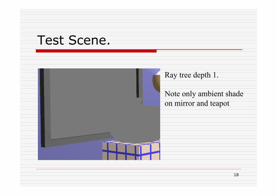
Test Scene.
Ray tree depth 1. Note only ambient shade on mirror and teapot
19
12/03/15
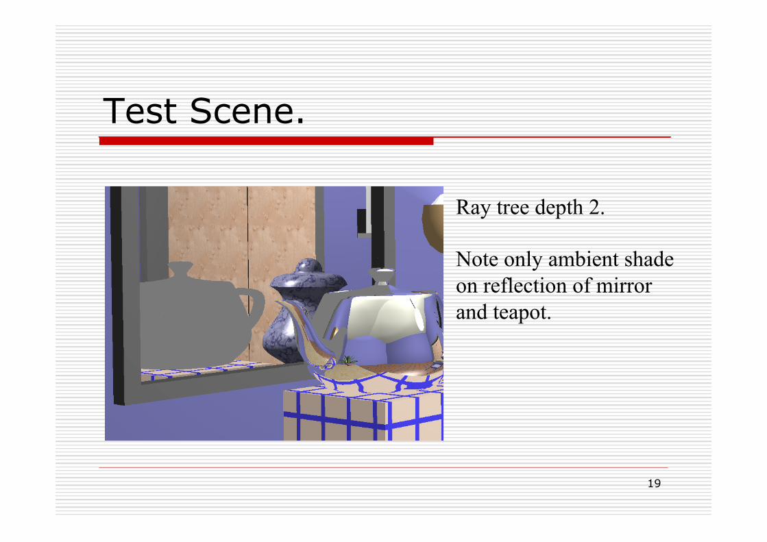
Test Scene.
Ray tree depth 2. Note only ambient shade on reflection of mirror and teapot.
20
12/03/15
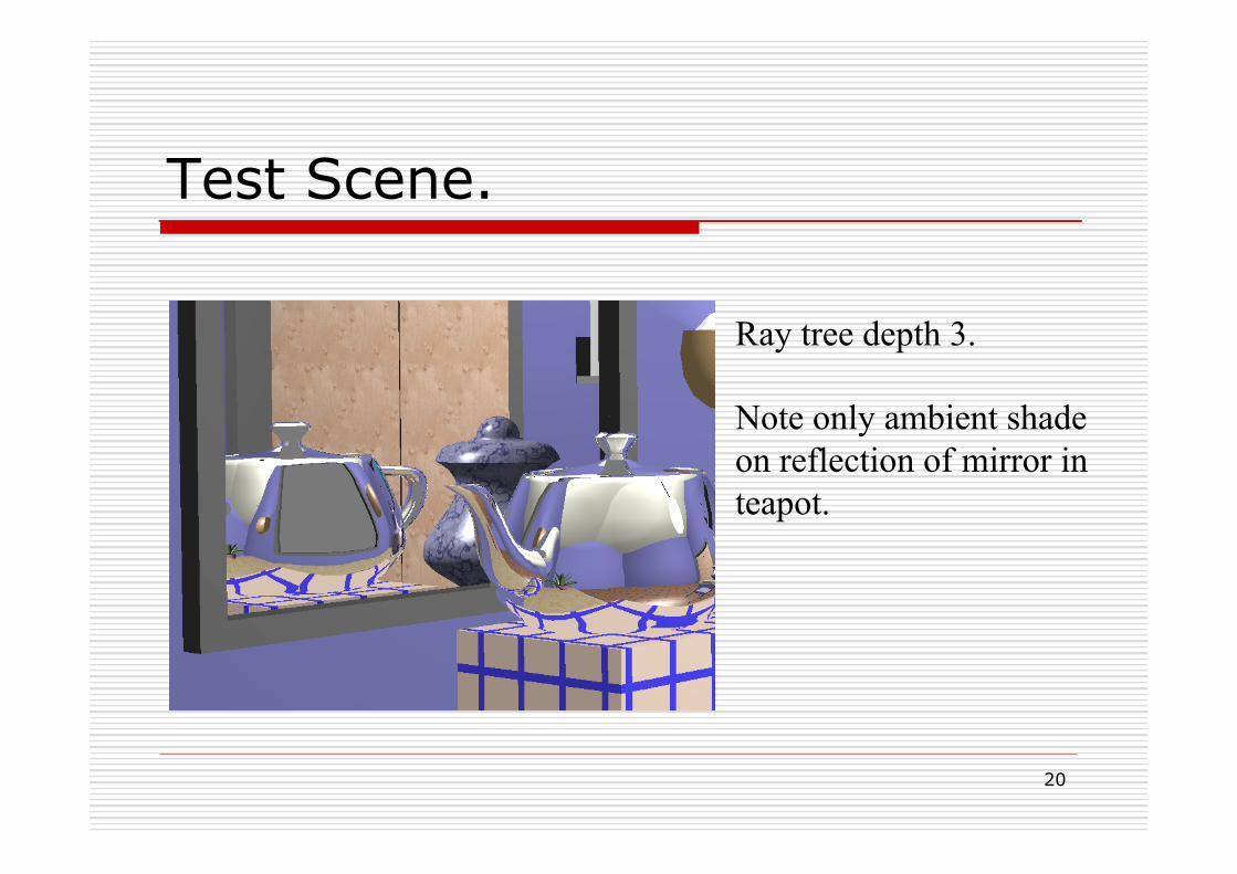
Test Scene.
Ray tree depth 3. Note only ambient shade on reflection of mirror in teapot.
21
12/03/15
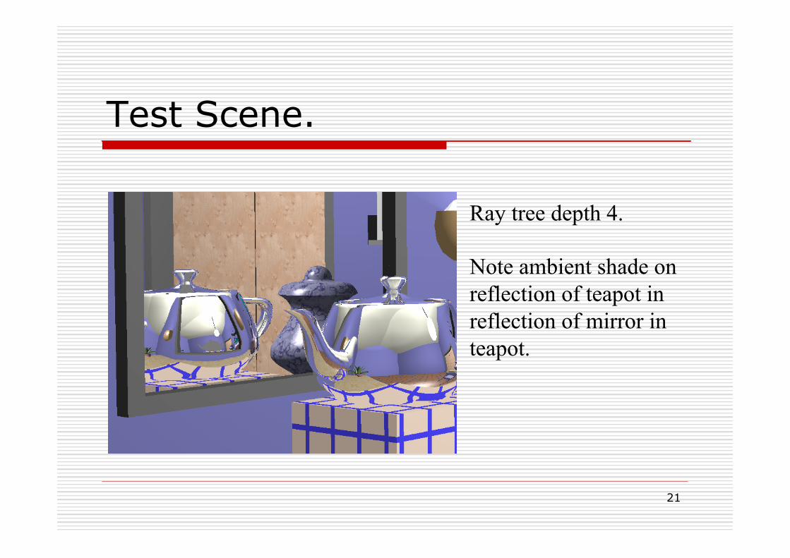
Test Scene.
Ray tree depth 4. Note ambient shade on reflection of teapot in reflection of mirror in teapot.

22
12/03/15
Test Scene.
Ray tree depth 5.

23
12/03/15
Test Scene.
Ray tree depth 6.
24
12/03/15
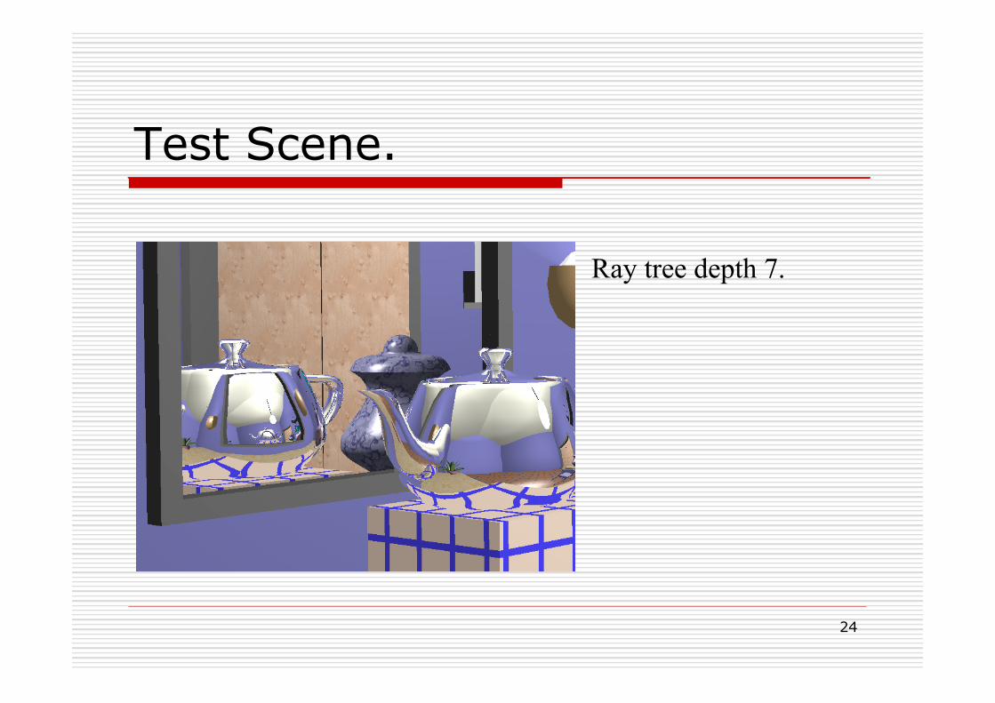
Test Scene.
Ray tree depth 7.
25
12/03/15
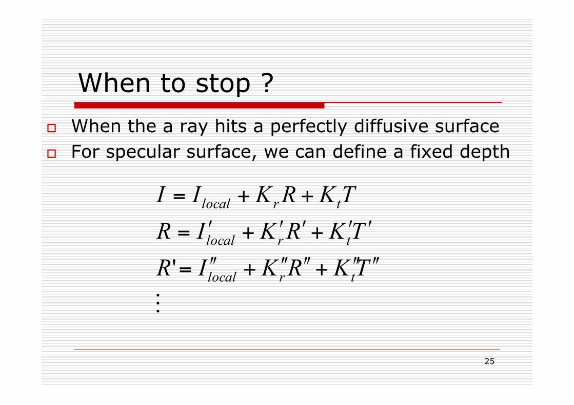
When to stop ? o When the a ray hits a perfectly diffusive surface o For specular surface, we can define a fixed depth
!
TKRKIRTKRKIRTKRKII
trlocal
trlocal
trlocal
ʹ′ʹ′ʹ′ʹ′+ʹ′ʹ′ʹ′ʹ′+ʹ′ʹ′=
ʹ′ʹ′+ʹ′ʹ′+ʹ′=
++=
'

Adaptive tree depth control. n Calculate maximum contribution of a ray to a pixels
final value. n For example, if the surface is more diffusive, smaller
influence from the reflection ray n Multiply contribution of ray’s ancestors down the tree. n Stop when below some threshold
n In the case above, stop when
Hall, R. A. and Greenberg D.P. , "A Testbed for Realistic Image Synthesis", IEEE Computer Graphics and Applications, 3(8), Nov., 1983
(...))))((( rlocalrlocalrlocalrlocal KIKIKIKII ʹ′ʹ′ʹ′+ʹ′ʹ′ʹ′ʹ′ʹ′+ʹ′ʹ′ʹ′+ʹ′+=
thresholdKKKK rrrr <ʹ′ʹ′ʹ′ʹ′ʹ′ʹ′ ...
27
12/03/15
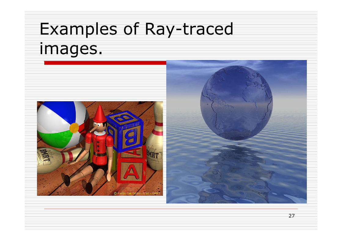
Examples of Ray-traced images.
28
12/03/15
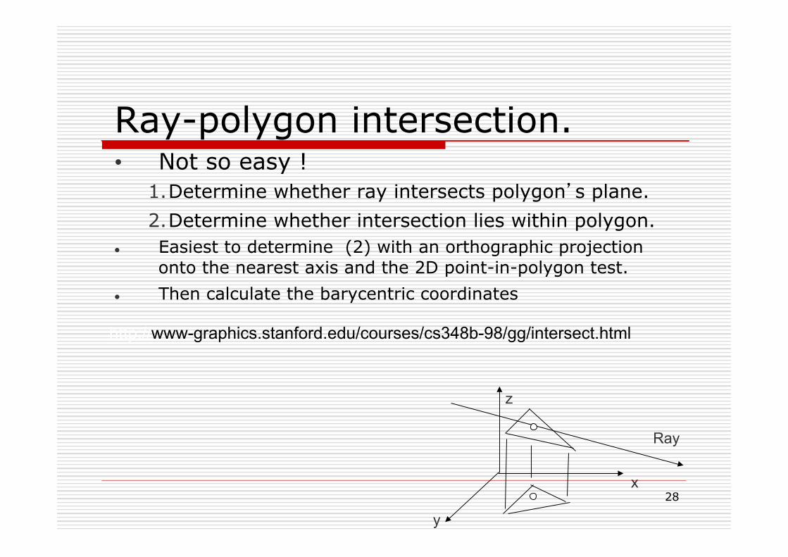
Ray-polygon intersection. • Not so easy !
1. Determine whether ray intersects polygon’s plane. 2. Determine whether intersection lies within polygon.
l Easiest to determine (2) with an orthographic projection onto the nearest axis and the 2D point-in-polygon test.
l Then calculate the barycentric coordinates
Ray
x
y
z
http://www-graphics.stanford.edu/courses/cs348b-98/gg/intersect.html
29
12/03/15
Accelerating Ray Tracers
o Ray Tracing is very time-consuming because of intersection calculations
o Solutions: n Use faster machines n Use specialized hardware, especially parallel processors. n Use perspective projection for the first ray n Use a larger threshold for adaptive depth tree control n Reduce the number of rays / polygon intersection check
o Bounding volumes
30
12/03/15
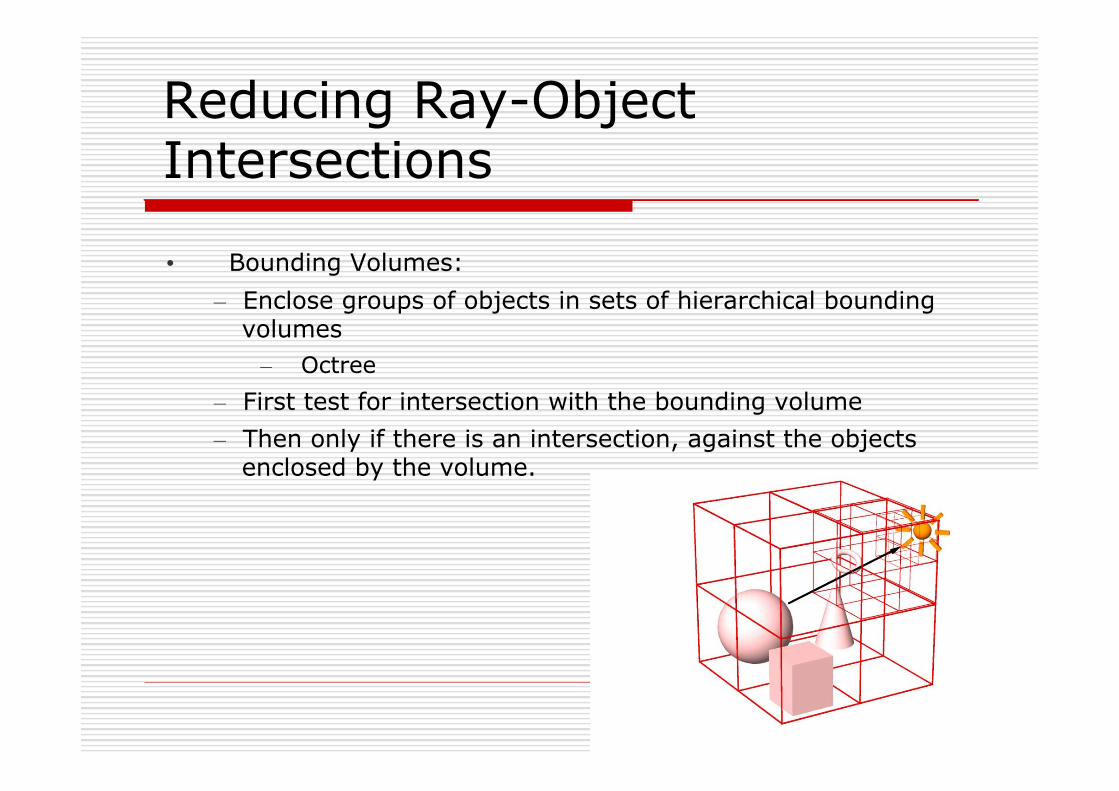
Reducing Ray-Object Intersections • Bounding Volumes:
– Enclose groups of objects in sets of hierarchical bounding volumes
– Octree – First test for intersection with the bounding volume – Then only if there is an intersection, against the objects
enclosed by the volume.
31
12/03/15
Ray Tracing : Drawbacks o Can we produce soft shadows? o Can we produce bleeding effects? o Can we render caustics? o Can we generate shadows of
refractive objects?
32
12/03/15
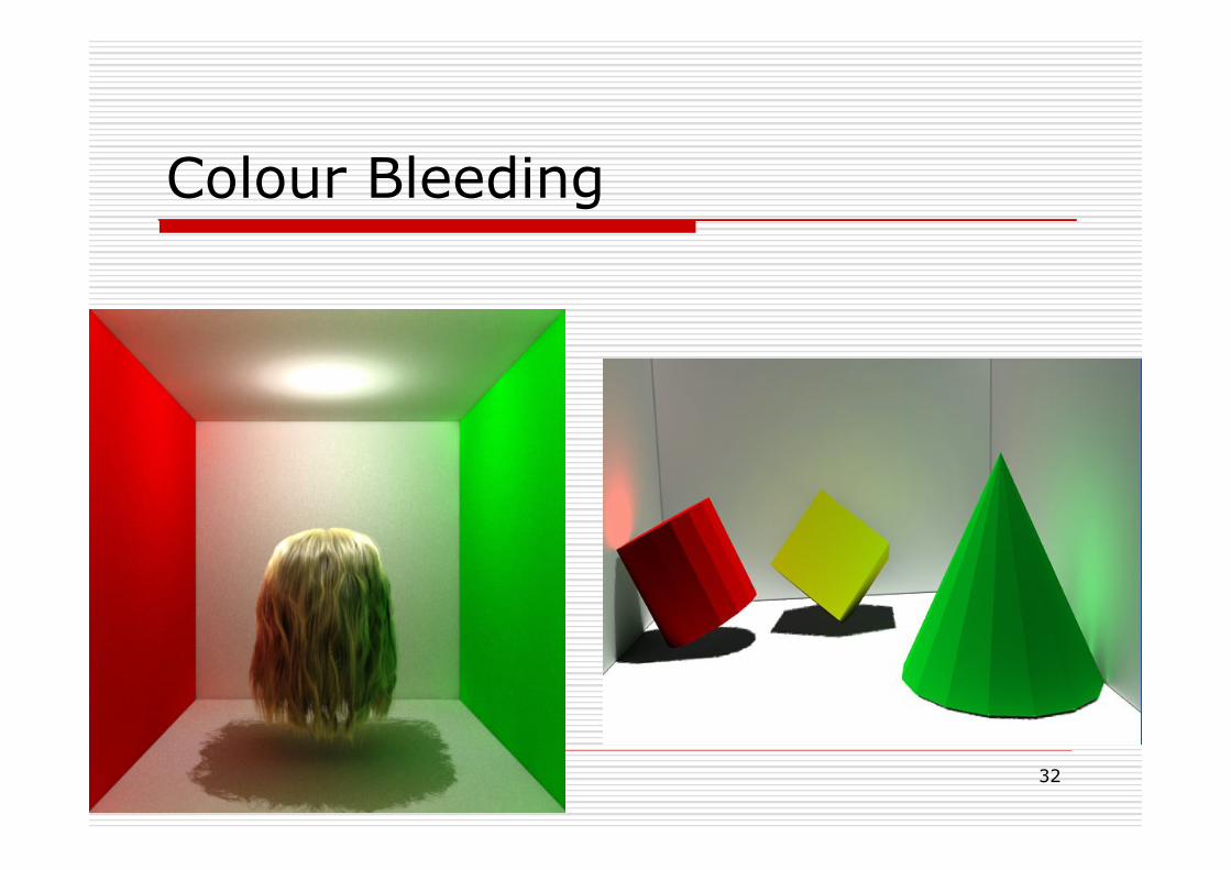
Colour Bleeding

33
12/03/15
Caustics

34
12/03/15
Tough Cases
o Caustics n Light focuses through a specular
surface onto a diffuse surface n Which direction should secondary
rays be cast to detect caustic? o Bleeding
n Color of diffuse surface reflected in another diffuse surface
n Which direction should secondary rays be cast to detect bleeding?
Tracking the light source after hitting diffuse surface is not very easy
35
6/11/2007
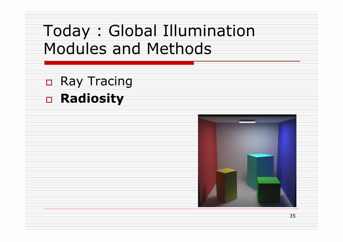
Today : Global Illumination Modules and Methods
o Ray Tracing o Radiosity
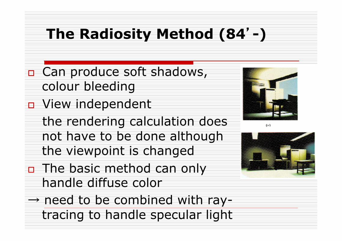
The Radiosity Method (84’-)
o Can produce soft shadows, colour bleeding
o View independent the rendering calculation does not have to be done although the viewpoint is changed
o The basic method can only handle diffuse color
→ need to be combined with ray-tracing to handle specular light
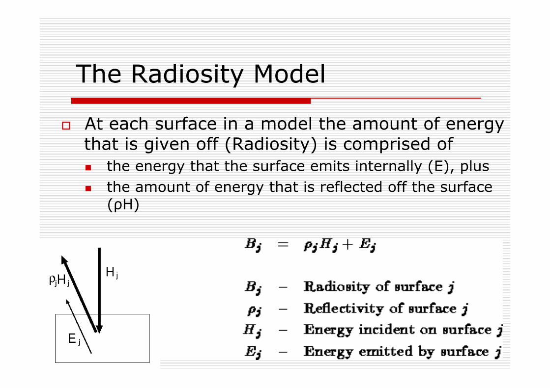
The Radiosity Model
o At each surface in a model the amount of energy that is given off (Radiosity) is comprised of n the energy that the surface emits internally (E), plus n the amount of energy that is reflected off the surface
(ρH)
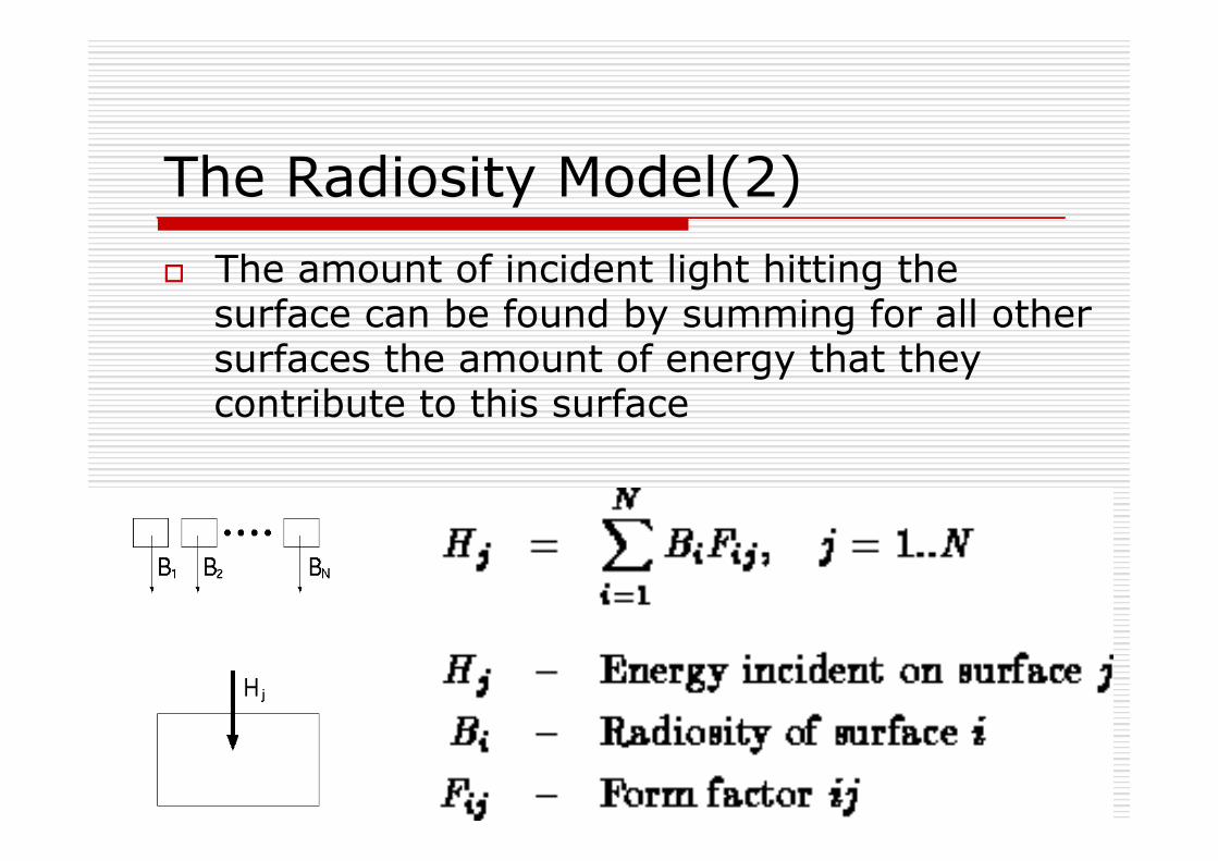
The Radiosity Model(2) o The amount of incident light hitting the
surface can be found by summing for all other surfaces the amount of energy that they contribute to this surface
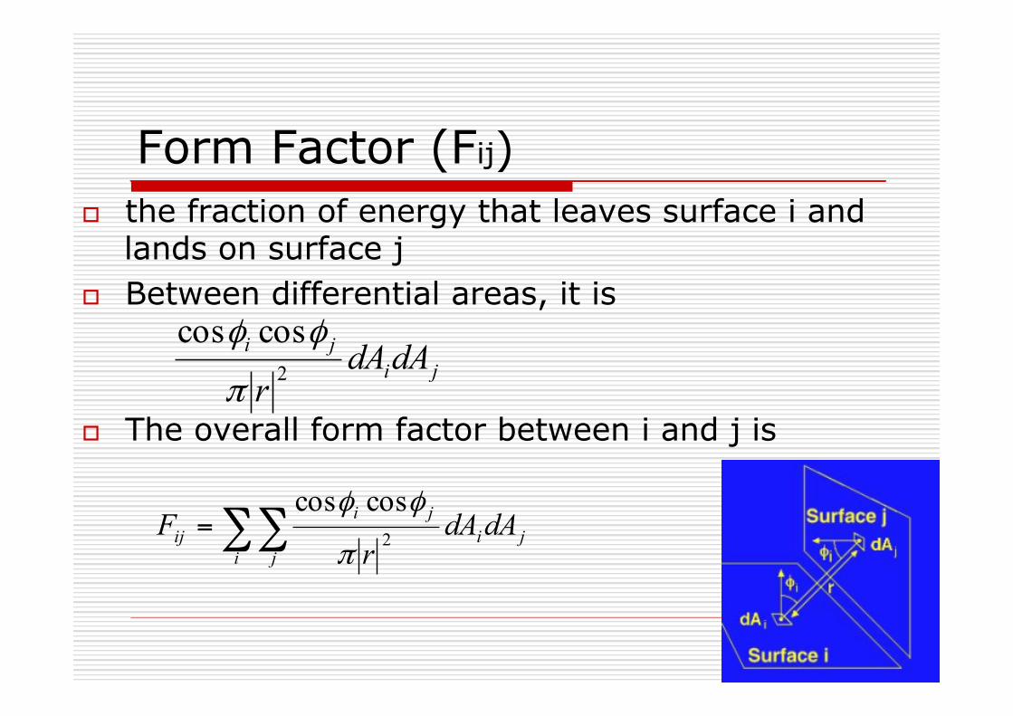
Form Factor (Fij) o the fraction of energy that leaves surface i and
lands on surface j o Between differential areas, it is o The overall form factor between i and j is ∑∑=
i jji
jiij dAdA
rF 2
coscos
π
φφ
jiji dAdA
r 2coscos
π
φφ

The Radiosity Matrix
The radiosity equation now looks like this: The derived radiosity equations form a set of N linear equations in N unknowns. This leads nicely to a matrix solution:

Radiosity Steps:
1 - Generate Model 2 - Compute Form Factors 3 - Solve Radiosity Matrix 4 – Render • Only if the geometry of the model is changed must the system start over from step 1. • If objects are moved, start over from step 2. • If the lighting or reflectance parameters of the scene are modified the system may start over from step 3. • If the view parameters are changed, the system must merely re-render the scene (step 4).
Radiosity Features:
o The faces must be subdivided into small patches to reduce the artifacts
o The computational cost for calculating the form factors is expensive n Quadratic to the number of patches
o Solving for Bi is also very costly o Cannot handle specular light
43
12/03/15
Recommended Reading
o Foley at al. Chapter 16, sections 16.11, 16.12 and 16.12.5.
o Introductory text Chapter 14 sections 14.6 and 14.7.
o An Efficient Ray-Polygon Intersection by Didier Badouel from Graphics Gems I
o Most graphics texts cover recursive ray tracing.
Recommended


![Progressive Photon Mapping - 東京大学hachisuka/starpm2012/PPM_Basics.pdf · Global Illumination Algorithms • Path Tracing [Kajiya 86] • Light Tracing [Arvo 86][Dutré 93]](https://img.pdfslide.us/doc/110x75/5f0d2ea27e708231d439135c/progressive-photon-mapping-hachisukastarpm2012ppm-global-illumination.jpg)