8/13/2019 latitude-c400_Service Manual_en-us.pdf
http://slidepdf.com/reader/full/latitude-c400service-manualen-uspdf 1/41
Dell™ Latitude™ C400 Service Manualefore You Begin
ystem Components
eyboard
emory Module and Modem Daughter Card
ard Drive
Wireless Network Adapter
isplay Assembly and Display Latch
alm Restooling Fan
eserve Battery
ashing the BIOS
udio Board
ystem Board
attery Latch
n Assignments for I/O Connectors
Notes, Notices, and Cautions
NOTE: A NOTE indicates important information that helps you make better use of your computer.
NOTICE: A NOTICE indicates either potential damage to hardware or loss of data and tells you how to avoid theproblem.
CAUTION: A CAUTION indicates a potential for property damage, personal injury, or death.
nformation in this document is subject to change without notice.
2001 Dell Computer Corporation. All rights reserved.
eproduction in any manner whatsoever without the written permission of Dell Computer Corporation is strictly forbidden.
rademarks used in this text: Dell , the DELL logo, and Latitude are trademarks of Dell Computer Corporation; Intel is a registered trademark o
tel Corporation; Microsoft and Windows are registered trademarks of Microsoft Corporation.
ther trademarks and trade names may be used in this document to refer to either the entities claiming the marks and names or their producell Computer Corporation disclaims any proprietary interest in trademarks and trade names other than its own.
ctober 2001 Rev. A00
8/13/2019 latitude-c400_Service Manual_en-us.pdf
http://slidepdf.com/reader/full/latitude-c400service-manualen-uspdf 2/41
ack to Contents Page
Before You BeginDell™ Latitude™ C400 Service Manual
Preparing to Work Inside the Computer
Recommended Tools
Screw Identification
Preparing to Work Inside the Computer
NOTICE: Only a certified service technician should perform repairs on your computer. Damage due to servicing thatnot authorized by Dell is not covered by your warranty.
NOTICE: To avoid damaging the computer, perform the following steps before you begin working inside the comput
1. Make sure that the work surface is clean to prevent scratching the computer cover.
2. Save any work in progress and close all open application programs.
3. Turn off the computer and all attached devices.
NOTE: Make sure the computer is turned off and not in suspend-to-disk or hibernate mode. If you cannot shudown the computer using the computer's operating system, press and hold the power button for 4 seconds.
4. Make sure the computer is undocked.
5. Disconnect the computer from the electrical outlet.
6. To avoid possible damage to the system board, wait 10 to 20 seconds and then disconnect any attached devices.
7. Disconnect all other external cables from the computer, including the IDE modular bay cable (if connected).
8. Remove any installed PC Cards or plastic blanks from the PC Card slot.
9. Close the display and turn the computer upside down on a flat work surface.
NOTICE: To avoid damaging the system board, you must remove the battery before you service the computer.
10. Remove the battery from the battery bay.
11. To dissipate any static electricity while you work, use a wrist grounding strap or periodically touch an unpainted mesurface.
12. Handle components and cards with care. Do not touch the components or contacts on a card. Hold a card by it edgor by its metal mounting bracket. Hold internal components by their edges, not by their pins.
Recommended Tools
he procedures in this manual require the following tools:
#1 magnetized Phillips screwdriver
Small flat-blade screwdriver
8/13/2019 latitude-c400_Service Manual_en-us.pdf
http://slidepdf.com/reader/full/latitude-c400service-manualen-uspdf 3/41
5-mm nut driver
7-mm nut driver
Needle-nose pliers
Flash BIOS update program floppy disk or CD
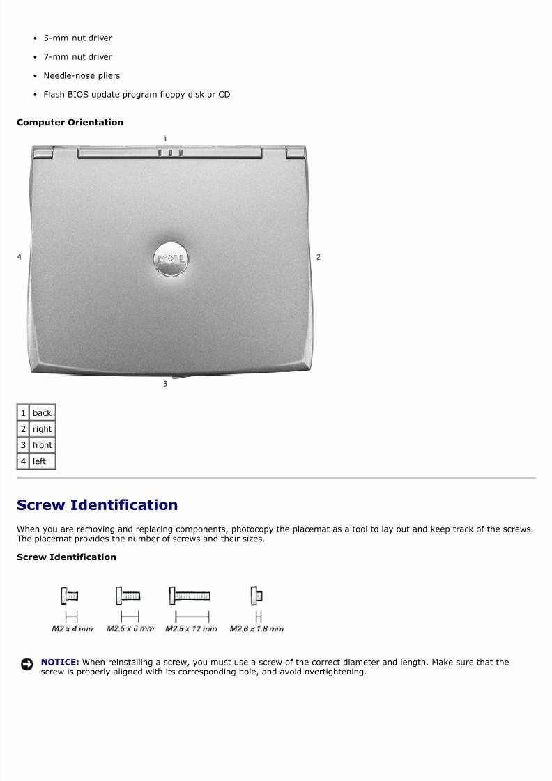
omputer Orientation
1 back
2 right
3 front
4 left
Screw Identification
When you are removing and replacing components, photocopy the placemat as a tool to lay out and keep track of the screhe placemat provides the number of screws and their sizes.
crew Identification
NOTICE: When reinstalling a screw, you must use a screw of the correct diameter and length. Make sure that thescrew is properly aligned with its corresponding hole, and avoid overtightening.
8/13/2019 latitude-c400_Service Manual_en-us.pdf
http://slidepdf.com/reader/full/latitude-c400service-manualen-uspdf 4/41
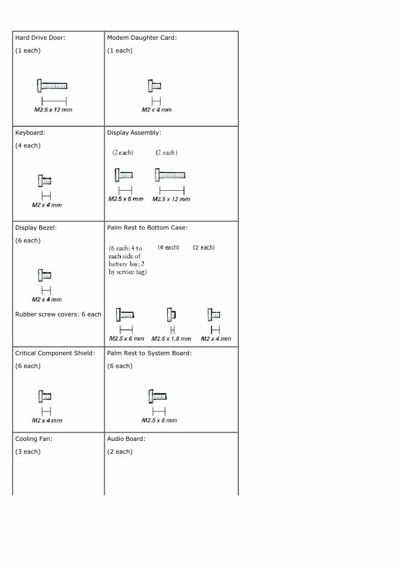
Hard Drive Door:
(1 each)
Modem Daughter Card:
(1 each)
Keyboard:
(4 each)
Display Assembly:
Display Bezel:
(6 each)
Rubber screw covers: 6 each
Palm Rest to Bottom Case:
Critical Component Shield:
(6 each)
Palm Rest to System Board:
(6 each)
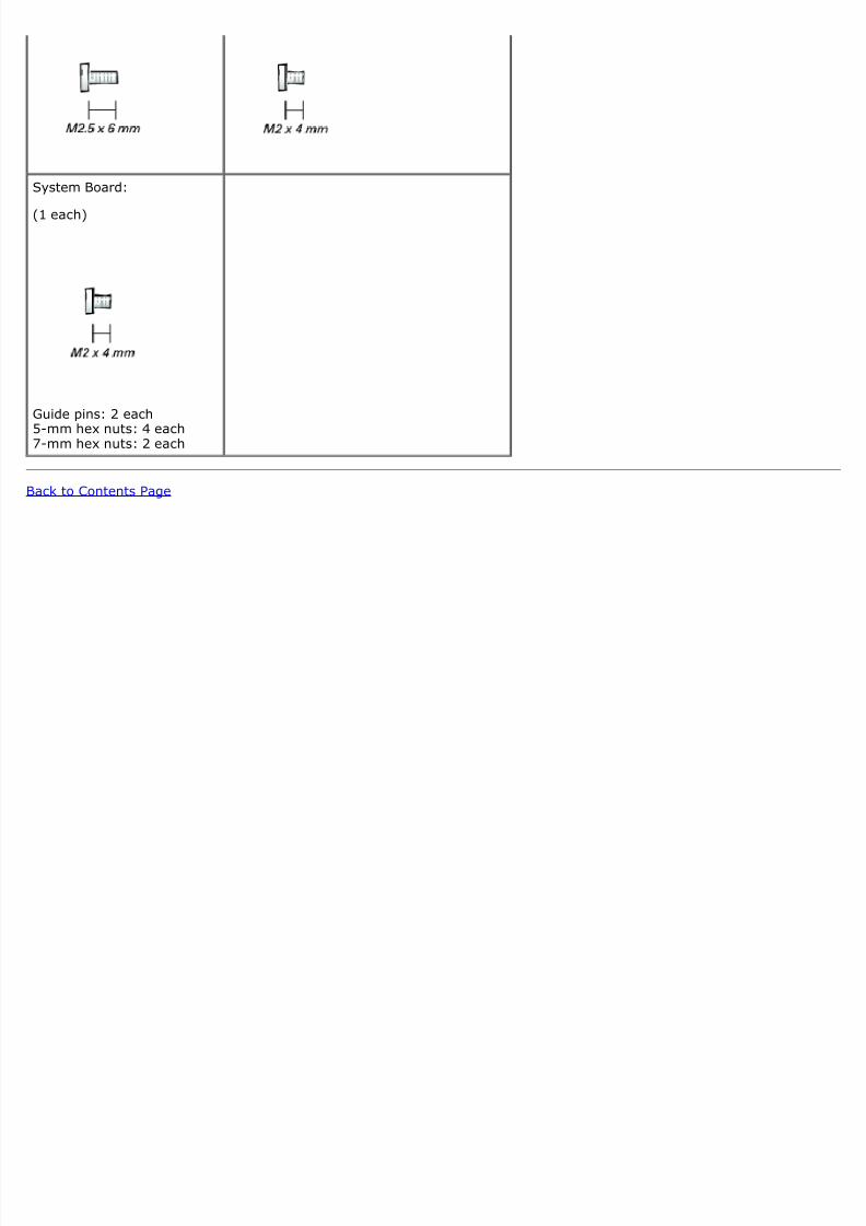
Cooling Fan:
(3 each)
Audio Board:
(2 each)
8/13/2019 latitude-c400_Service Manual_en-us.pdf
http://slidepdf.com/reader/full/latitude-c400service-manualen-uspdf 5/41
8/13/2019 latitude-c400_Service Manual_en-us.pdf
http://slidepdf.com/reader/full/latitude-c400service-manualen-uspdf 6/41
ack to Contents Page
System ComponentsDell™ Latitude™ C400 Service Manual
NOTICE: Only a certified service technician should perform repairs on your computer. Damage due to servicing thatnot authorized by Dell is not covered by your warranty.
NOTICE: Unless otherwise noted, each procedure in this manual assumes that a part can be replaced by performingthe removal procedure in reverse order.
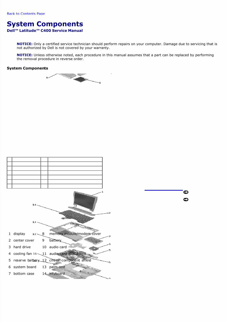
ystem Components
1 display 8 memory module/modem cover
2 center cover 9 battery
3 hard drive 10 audio card
4 cooling fan 11 audio card shield
5 reserve battery 12 critical component shield
6 system board 13 palm rest
7 bottom case 14 keyboard

8/13/2019 latitude-c400_Service Manual_en-us.pdf
http://slidepdf.com/reader/full/latitude-c400service-manualen-uspdf 7/41
ack to Contents Page
8/13/2019 latitude-c400_Service Manual_en-us.pdf
http://slidepdf.com/reader/full/latitude-c400service-manualen-uspdf 8/41
ack to Contents Page
KeyboardDell™ Latitude™ C400 Service Manual
Removing the Keyboard
Replacing the Keyboard
Removing the Keyboard
NOTICE: Disconnect the computer and any attached devices from electrical outlets, and remove any installedbatteries.
NOTICE: To avoid ESD, ground yourself by using a wrist grounding strap or by touching an unpainted metal surfacethe computer.
NOTICE: Read "Preparing to Work Inside the Computer" before performing the following procedure.
1. Remove the hard drive.
NOTICE: The key caps on the keyboard are fragile, easily dislodged, and time-consuming to replace. Be careful wheremoving and handling the keyboard.
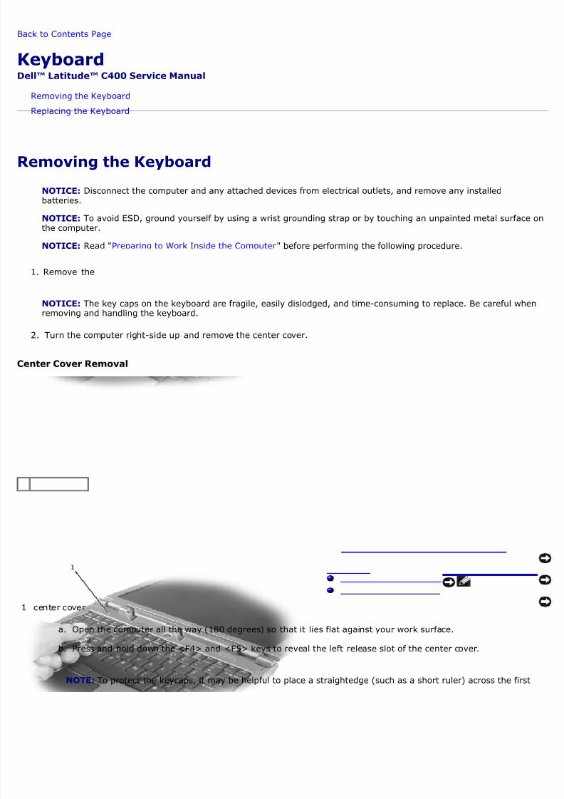
2. Turn the computer right-side up and remove the center cover.
enter Cover Removal
1 center cover
a. Open the computer all the way (180 degrees) so that it lies flat against your work surface.
b. Press and hold down the <F4> and <F5> keys to reveal the left release slot of the center cover.
NOTE: To protect the keycaps, it may be helpful to place a straightedge (such as a short ruler) across the first
8/13/2019 latitude-c400_Service Manual_en-us.pdf
http://slidepdf.com/reader/full/latitude-c400service-manualen-uspdf 9/41
row or two of keycaps, and press on the straightedge instead of on the keycaps themselves.
c. Insert a flat-blade screwdriver into the slot. While holding the screwdriver, make your hand into a fist, braceyour knuckles against the keyboard, and pry up the center cover.
d. Repeat steps b and c for the right release slot, located behind the <F9> and <F10> keys.
e. Lift the center cover up and away from the bottom case.
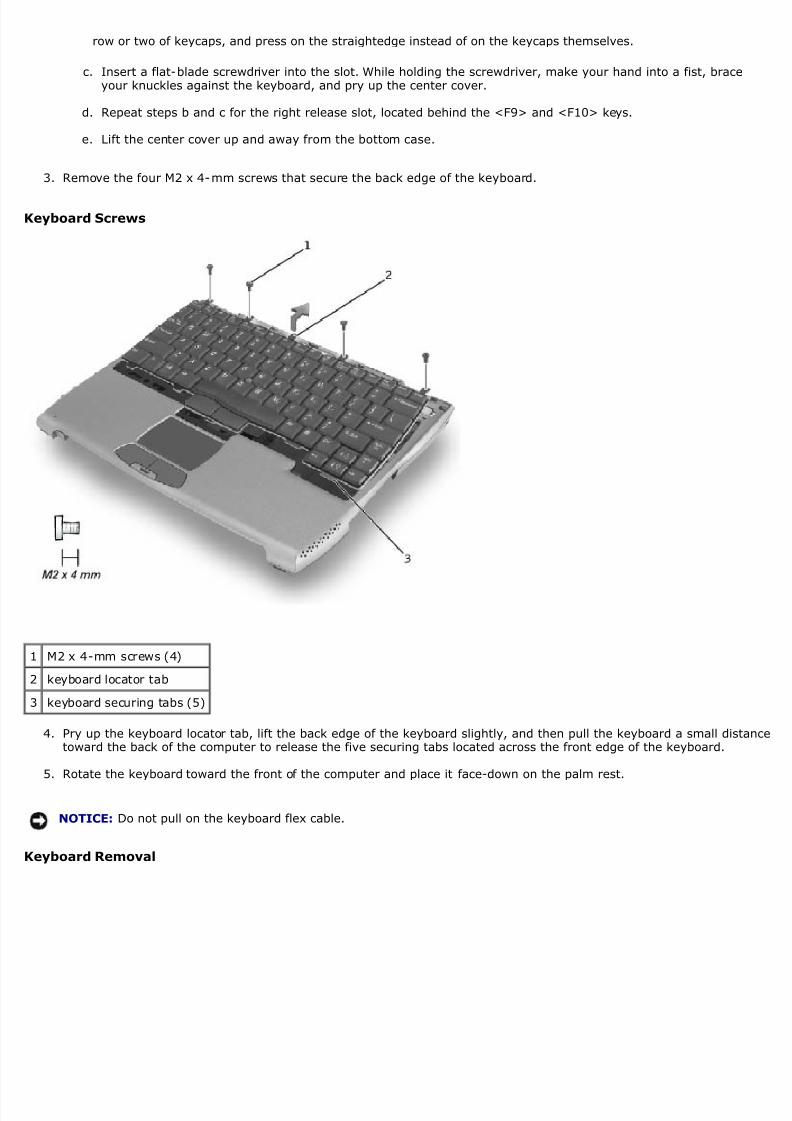
3. Remove the four M2 x 4-mm screws that secure the back edge of the keyboard.
Keyboard Screws
1 M2 x 4-mm screws (4)
2 keyboard locator tab
3 keyboard securing tabs (5)
4. Pry up the keyboard locator tab, lift the back edge of the keyboard slightly, and then pull the keyboard a small disttoward the back of the computer to release the five securing tabs located across the front edge of the keyboard.
5. Rotate the keyboard toward the front of the computer and place it face-down on the palm rest.
NOTICE: Do not pull on the keyboard flex cable.
Keyboard Removal
8/13/2019 latitude-c400_Service Manual_en-us.pdf
http://slidepdf.com/reader/full/latitude-c400service-manualen-uspdf 10/41
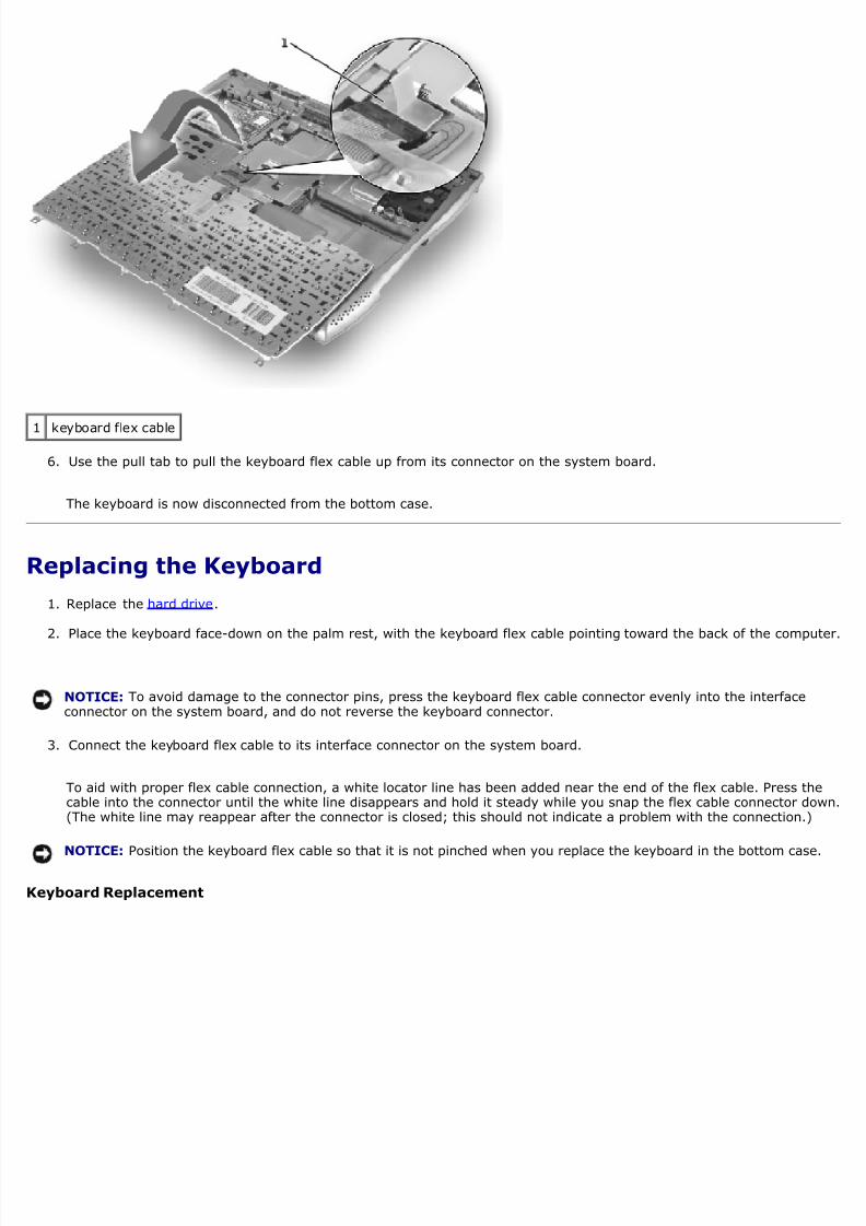
1 keyboard flex cable
6. Use the pull tab to pull the keyboard flex cable up from its connector on the system board.
The keyboard is now disconnected from the bottom case.
Replacing the Keyboard
1. Replace the hard drive.
2. Place the keyboard face-down on the palm rest, with the keyboard flex cable pointing toward the back of the comp
NOTICE: To avoid damage to the connector pins, press the keyboard flex cable connector evenly into the interfaceconnector on the system board, and do not reverse the keyboard connector.
3. Connect the keyboard flex cable to its interface connector on the system board.
To aid with proper flex cable connection, a white locator line has been added near the end of the flex cable. Press thcable into the connector until the white line disappears and hold it steady while you snap the flex cable connector do(The white line may reappear after the connector is closed; this should not indicate a problem with the connection.)
NOTICE: Position the keyboard flex cable so that it is not pinched when you replace the keyboard in the bottom case
Keyboard Replacement
8/13/2019 latitude-c400_Service Manual_en-us.pdf
http://slidepdf.com/reader/full/latitude-c400service-manualen-uspdf 11/41
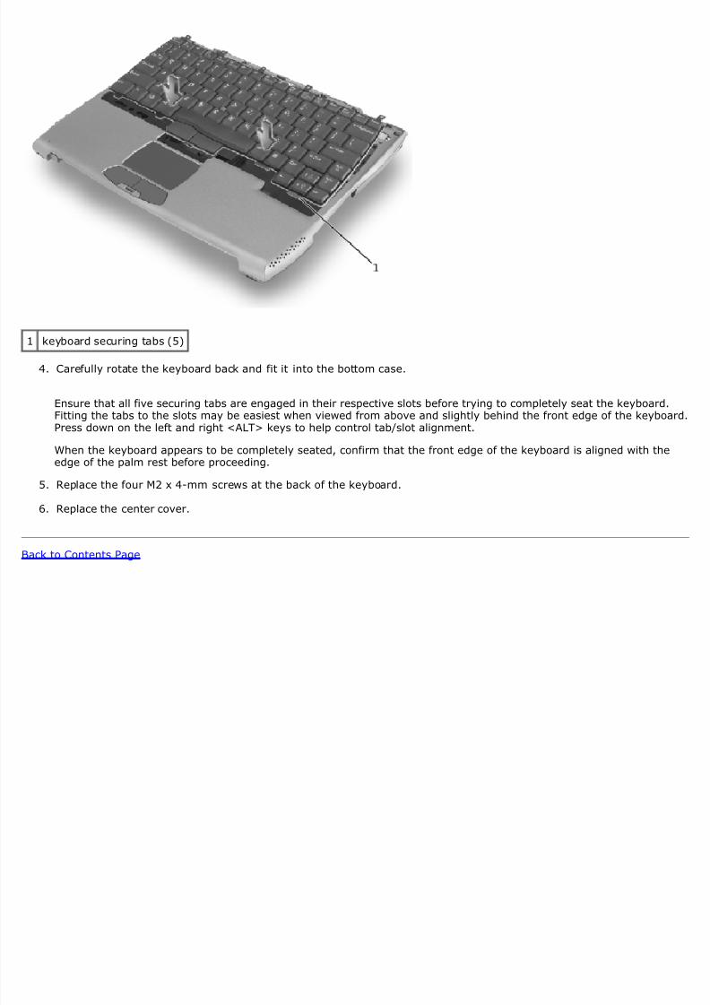
1 keyboard securing tabs (5)
4. Carefully rotate the keyboard back and fit it into the bottom case.
Ensure that all five securing tabs are engaged in their respective slots before trying to completely seat the keyboardFitting the tabs to the slots may be easiest when viewed from above and slightly behind the front edge of the keyboPress down on the left and right <ALT> keys to help control tab/slot alignment.
When the keyboard appears to be completely seated, confirm that the front edge of the keyboard is aligned with theedge of the palm rest before proceeding.
5. Replace the four M2 x 4-mm screws at the back of the keyboard.
6. Replace the center cover.
ack to Contents Page
8/13/2019 latitude-c400_Service Manual_en-us.pdf
http://slidepdf.com/reader/full/latitude-c400service-manualen-uspdf 12/41
ack to Contents Page
Memory Module and Modem Daughter CardDell™ Latitude™ C400 Service Manual
Removing the Memory Module/Modem Cover
Removing the Memory Modules
Replacing the Memory Modules
Removing the Modem Daughter Card
Replacing the Modem Daughter Card
Removing the Memory Module/Modem Cover
NOTE: This procedure covers removing and replacing the memory module located under the memory module/modecover on the bottom of the computer. A second memory module resides on the upper surface of the system boardunder the critical component shield. To replace the memory module under the critical component shield, perform theprocedure for removing the palm rest up to and including removal of the critical component shield. Then replace thememory module.
NOTICE: Disconnect the computer and any attached devices from electrical outlets, and remove any installedbatteries.
NOTICE: To avoid ESD, ground yourself by using a wrist grounding strap or by touching an unpainted metal surfacethe computer.
NOTICE: Read "Preparing to Work Inside the Computer" before performing the following procedure.
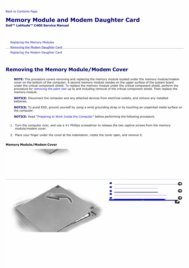
1. Turn the computer over, and use a #1 Phillips screwdriver to release the two captive screws from the memorymodule/modem cover.
2. Place your finger under the cover at the indentation, rotate the cover open, and remove it.
Memory Module/Modem Cover
8/13/2019 latitude-c400_Service Manual_en-us.pdf
http://slidepdf.com/reader/full/latitude-c400service-manualen-uspdf 13/41
Removing the Memory Modules
NOTICE: Disconnect the computer and any attached devices from electrical outlets, and remove the battery.
NOTICE: To avoid ESD, ground yourself by using a wrist grounding strap or by touching an unpainted metal surfacethe computer.
NOTICE: Read "Preparing to Work Inside the Computer" before performing the following procedure.
1. Remove the memory module/modem cover.
NOTICE: To prevent damage to the memory module connector, do not use tools to spread the inner metal tabs thasecure the memory module.
2. Use your fingertips to carefully spread apart the inner tabs on each end of the memory module socket.
The module should pop up.
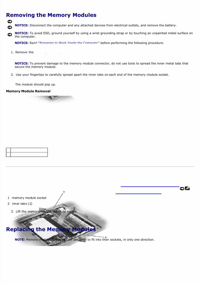
Memory Module Removal
1 memory module socket2 inner tabs (2)
3. Lift the memory module out of its socket.
Replacing the Memory Modules
NOTE: Memory modules are keyed, or designed to fit into their sockets, in only one direction.
8/13/2019 latitude-c400_Service Manual_en-us.pdf
http://slidepdf.com/reader/full/latitude-c400service-manualen-uspdf 14/41
NOTICE: The memory module must be inserted at a 45-degree angle to avoid damaging the connector.
1. Align the notch in the memory module with the slot in the center of the socket.
2. Slide the edge connector of the module firmly into the socket at a 45- degree angle, and rotate the module down uyou hear a click. If you do not hear the click, remove the module and reinstall it.
3. Replace the cover and tighten the two captive screws.
Removing the Modem Daughter Card
NOTICE: Disconnect the computer and any attached devices from electrical outlets, and remove the battery.
NOTICE: To avoid ESD, ground yourself by using a wrist grounding strap or by touching an unpainted metal surfacethe computer.
NOTICE: Read "Preparing to Work Inside the Computer" before performing the following procedure.
1. Turn the computer over, and remove the memory module/modem cover.
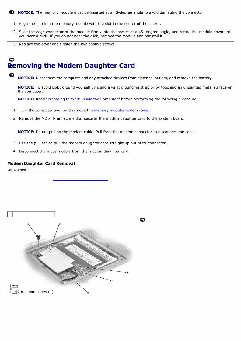
2. Remove the M2 x 4-mm screw that secures the modem daughter card to the system board.
NOTICE: Do not pull on the modem cable. Pull from the modem connector to disconnect the cable.
3. Use the pull tab to pull the modem daughter card straight up out of its connector.
4. Disconnect the modem cable from the modem daughter card.
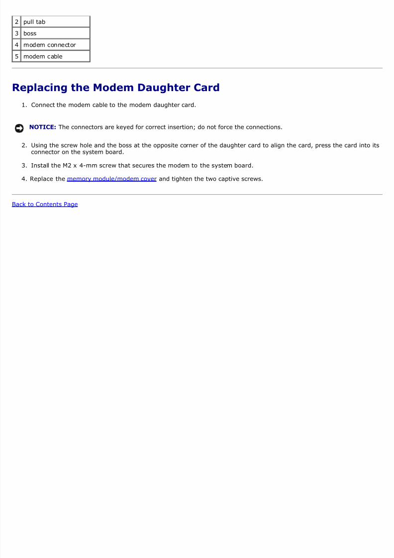
Modem Daughter Card Removal
1 M2 x 4-mm screw (1)
8/13/2019 latitude-c400_Service Manual_en-us.pdf
http://slidepdf.com/reader/full/latitude-c400service-manualen-uspdf 15/41
2 pull tab
3 boss
4 modem connector
5 modem cable
Replacing the Modem Daughter Card
1. Connect the modem cable to the modem daughter card.
NOTICE: The connectors are keyed for correct insertion; do not force the connections.
2. Using the screw hole and the boss at the opposite corner of the daughter card to align the card, press the card intoconnector on the system board.
3. Install the M2 x 4-mm screw that secures the modem to the system board.
4. Replace the memory module/modem cover and tighten the two captive screws.
ack to Contents Page
8/13/2019 latitude-c400_Service Manual_en-us.pdf
http://slidepdf.com/reader/full/latitude-c400service-manualen-uspdf 16/41
ack to Contents Page
Hard DriveDell™ Latitude™ C400 Service Manual
Removing the Hard Drive
Replacing the Hard Drive
Removing the Hard Drive
1. Save and close any open files, exit any open programs, and shut down the computer.
NOTICE: Disconnect the computer and any attached devices from electrical outlets, and remove the battery.
NOTICE: The hard drive is very sensitive to shock. Handle the hard drive by its edges (do not squeeze the top of thhard drive case), and avoid dropping it.
NOTICE: Read "Preparing to Work Inside the Computer" before performing the following procedure.
NOTICE: To prevent data loss, turn off your computer before removing the hard drive. Do not remove the hard drivwhile the computer is on, in standby mode or in hibernate mode.
CAUTION: If you remove the hard drive from the computer when the drive is hot, d o n o t t o u c h the metahousing of the hard drive.
2. Ground yourself by touching a metal connector on the back of the computer.
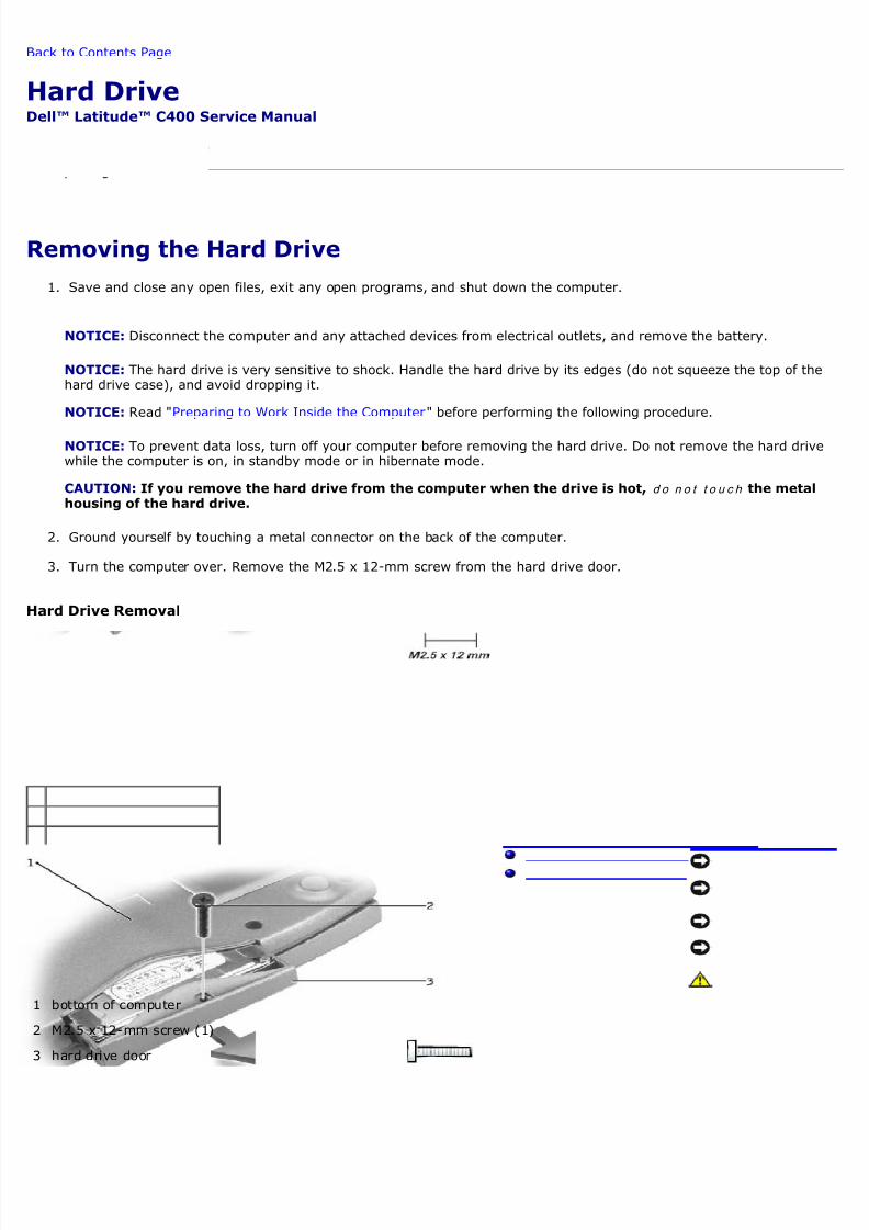
3. Turn the computer over. Remove the M2.5 x 12-mm screw from the hard drive door.
ard Drive Removal
1 bottom of computer
2 M2.5 x 12-mm screw (1)
3 hard drive door

8/13/2019 latitude-c400_Service Manual_en-us.pdf
http://slidepdf.com/reader/full/latitude-c400service-manualen-uspdf 17/41
4. Slide the hard drive straight out of the computer.
Replacing the Hard Drive
NOTICE: Use firm and even pressure to slide the hard drive into place. If you force the hard drive into place usingexcessive force, you may damage the connector.
1. Push the hard drive into the drive bay until it is fully seated in the bay.
2. Replace the M2.5 x 12-mm screw in the hard drive door.
ack to Contents Page
8/13/2019 latitude-c400_Service Manual_en-us.pdf
http://slidepdf.com/reader/full/latitude-c400service-manualen-uspdf 18/41
ack to Contents Page
Wireless Network AdapterDell™ Latitude™ C400 Service Manual
Removing the Wireless Network Adapter
Replacing the Wireless Network Adapter
Removing the Wireless Network Adapter
NOTICE: Disconnect the computer and any attached devices from electrical outlets, and remove any installedbatteries.
NOTICE: To avoid ESD, ground yourself by using a wrist grounding strap or by touching an unpainted metal surfacethe computer.
NOTICE: Read "Preparing to Work Inside the Computer" before performing the following procedure.
1. Remove the hard drive.
2. Remove the keyboard.
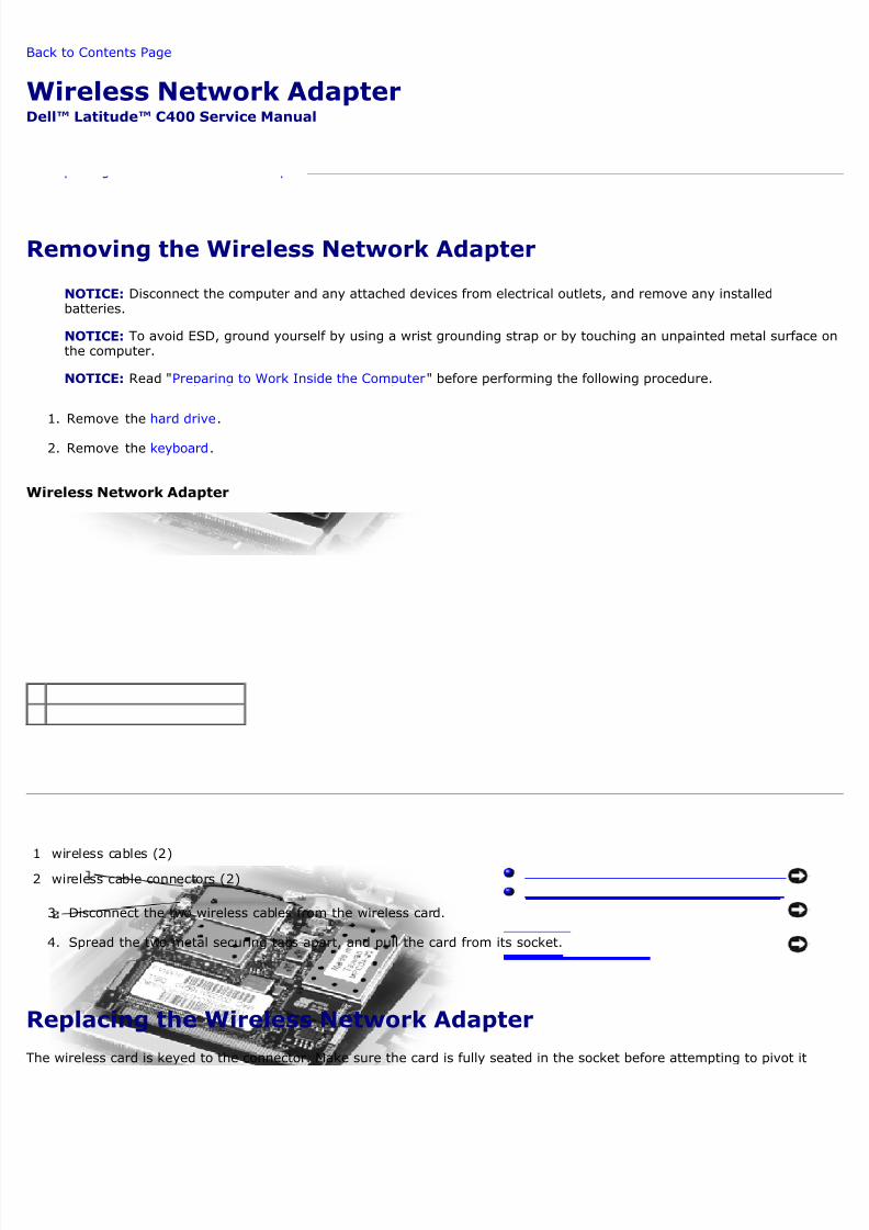
Wireless Network Adapter
1 wireless cables (2)
2 wireless cable connectors (2)
3. Disconnect the two wireless cables from the wireless card.
4. Spread the two metal securing tabs apart, and pull the card from its socket.
Replacing the Wireless Network Adapter
he wireless card is keyed to the connector. Make sure the card is fully seated in the socket before attempting to pivot it

8/13/2019 latitude-c400_Service Manual_en-us.pdf
http://slidepdf.com/reader/full/latitude-c400service-manualen-uspdf 19/41
own into place.
ack to Contents Page
8/13/2019 latitude-c400_Service Manual_en-us.pdf
http://slidepdf.com/reader/full/latitude-c400service-manualen-uspdf 20/41
ack to Contents Page
Display Assembly and Display LatchDell™ Latitude™ C400 Service Manual
Removing the Display Assembly
Replacing the Display Latch
Removing the Display Assembly
NOTICE: You must remove the display assembly before you remove the palm rest.
NOTICE: Disconnect the computer and any attached devices from electrical outlets, and remove any installedbatteries.
NOTICE: To avoid ESD, ground yourself by using a wrist grounding strap or by touching an unpainted metal surfacethe computer.
NOTICE: Read "Preparing to Work Inside the Computer" before performing the following procedure.
1. Remove the battery.
2. Remove the hard drive.
3. Remove the center cover.
4. Close the display.
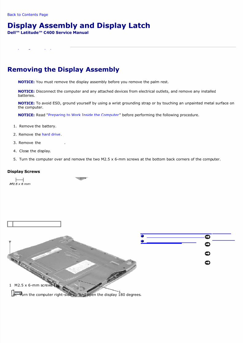
5. Turn the computer over and remove the two M2.5 x 6-mm screws at the bottom back corners of the computer.
Display Screws
1 M2.5 x 6-mm screws (2)
6. Turn the computer right-side up and open the display 180 degrees.
8/13/2019 latitude-c400_Service Manual_en-us.pdf
http://slidepdf.com/reader/full/latitude-c400service-manualen-uspdf 21/41
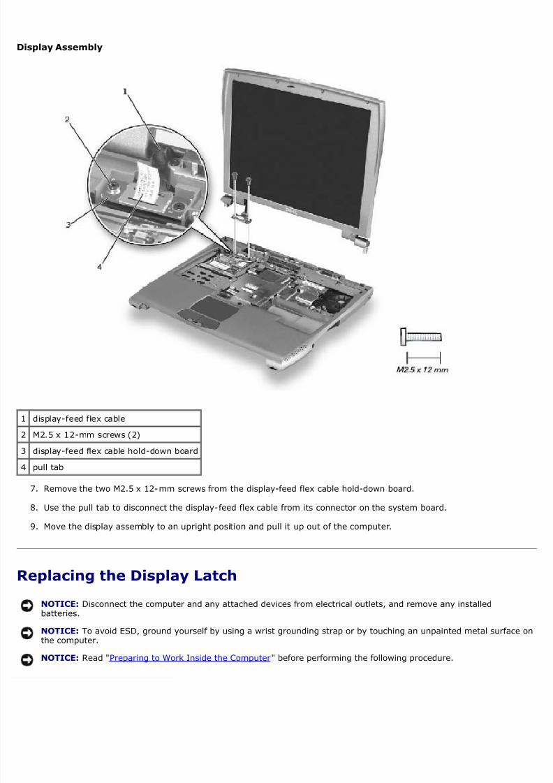
Display Assembly
1 display-feed flex cable
2 M2.5 x 12-mm screws (2)
3 display-feed flex cable hold-down board
4 pull tab
7. Remove the two M2.5 x 12-mm screws from the display-feed flex cable hold-down board.
8. Use the pull tab to disconnect the display-feed flex cable from its connector on the system board.
9. Move the display assembly to an upright position and pull it up out of the computer.
Replacing the Display Latch
NOTICE: Disconnect the computer and any attached devices from electrical outlets, and remove any installedbatteries.
NOTICE: To avoid ESD, ground yourself by using a wrist grounding strap or by touching an unpainted metal surfacethe computer.
NOTICE: Read "Preparing to Work Inside the Computer" before performing the following procedure.
8/13/2019 latitude-c400_Service Manual_en-us.pdf
http://slidepdf.com/reader/full/latitude-c400service-manualen-uspdf 22/41
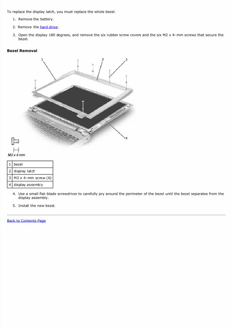
o replace the display latch, you must replace the whole bezel.
1. Remove the battery.
2. Remove the hard drive.
3. Open the display 180 degrees, and remove the six rubber screw covers and the six M2 x 4-mm screws that secure bezel.
ezel Removal
1 bezel
2 display latch3 M2 x 4-mm screw (6)
4 display assembly
4. Use a small flat-blade screwdriver to carefully pry around the perimeter of the bezel until the bezel separates from display assembly.
5. Install the new bezel.
ack to Contents Page
8/13/2019 latitude-c400_Service Manual_en-us.pdf
http://slidepdf.com/reader/full/latitude-c400service-manualen-uspdf 23/41
ack to Contents Page
Palm RestDell™ Latitude™ C400 Service Manual
Removing the Palm Rest
Replacing the Palm Rest
Removing the Palm Rest
NOTICE: Disconnect the computer and any attached devices from electrical outlets, and remove any installedbatteries.
NOTICE: To avoid ESD, ground yourself by using a wrist grounding strap or by touching an unpainted metal surfacethe computer.
NOTICE: Read "Preparing to Work Inside the Computer" before performing the following procedure.
1. Remove the hard drive.
2. Remove the keyboard.
NOTICE: You must remove the display assembly before you remove the palm rest; the display hinges pass throughthe back of the palm rest.
3. Remove the display assembly.
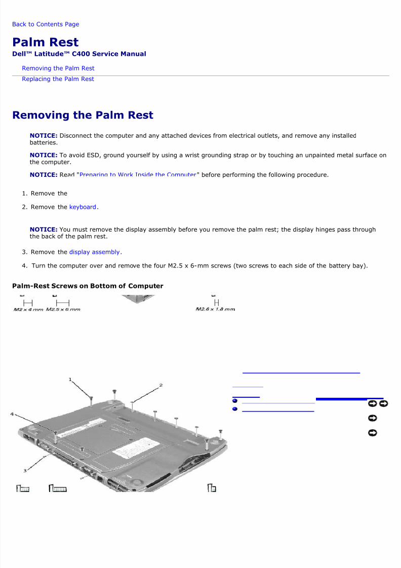
4. Turn the computer over and remove the four M2.5 x 6-mm screws (two screws to each side of the battery bay).
alm-Rest Screws on Bottom of Computer
8/13/2019 latitude-c400_Service Manual_en-us.pdf
http://slidepdf.com/reader/full/latitude-c400service-manualen-uspdf 24/41
1 M2.5 x 6-mm screws (4)
2 M2.6 x 1.8-mm screws (4)
3 M2 x 4-mm screws (2)
4 M2.5 x 6-mm screws (2)
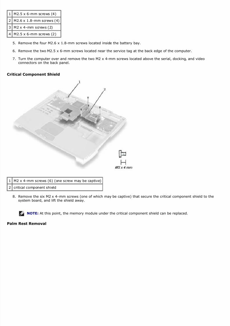
5. Remove the four M2.6 x 1.8-mm screws located inside the battery bay.
6. Remove the two M2.5 x 6-mm screws located near the service tag at the back edge of the computer.
7. Turn the computer over and remove the two M2 x 4-mm screws located above the serial, docking, and videoconnectors on the back panel.
ritical Component Shield
1 M2 x 4-mm screws (6) (one screw may be captive)
2 critical component shield
8. Remove the six M2 x 4-mm screws (one of which may be captive) that secure the critical component shield to thesystem board, and lift the shield away.
NOTE: At this point, the memory module under the critical component shield can be replaced.
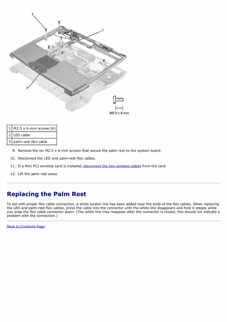
alm Rest Removal
8/13/2019 latitude-c400_Service Manual_en-us.pdf
http://slidepdf.com/reader/full/latitude-c400service-manualen-uspdf 25/41
1 M2.5 x 6-mm screws (6)
2 LED cable
3 palm-rest flex cable
9. Remove the six M2.5 x 6-mm screws that secure the palm rest to the system board.
10. Disconnect the LED and palm-rest flex cables.
11. If a Mini PCI wireless card is installed, disconnect the two wireless cables from the card.
12. Lift the palm rest away.
Replacing the Palm Rest
o aid with proper flex cable connection, a white locator line has been added near the ends of the flex cables. When replache LED and palm-rest flex cables, press the cable into the connector until the white line disappears and hold it steady whou snap the flex cable connector down. (The white line may reappear after the connector is closed; this should not indicaroblem with the connection.)
ack to Contents Page
8/13/2019 latitude-c400_Service Manual_en-us.pdf
http://slidepdf.com/reader/full/latitude-c400service-manualen-uspdf 26/41
ack to Contents Page
Cooling FanDell™ Latitude™ C400 Service Manual
Removing the Cooling Fan
Removing the Cooling Fan
NOTICE: Disconnect the computer and any attached devices from electrical outlets, and remove any installedbatteries.
NOTICE: To avoid ESD, ground yourself by using a wrist grounding strap or by touching an unpainted metal surfacethe computer.
NOTICE: Read "Preparing to Work Inside the Computer" before performing the following procedure.
1. Remove the hard drive.
2. Remove the keyboard.
3. Remove the display assembly.
4. Remove the palm rest.
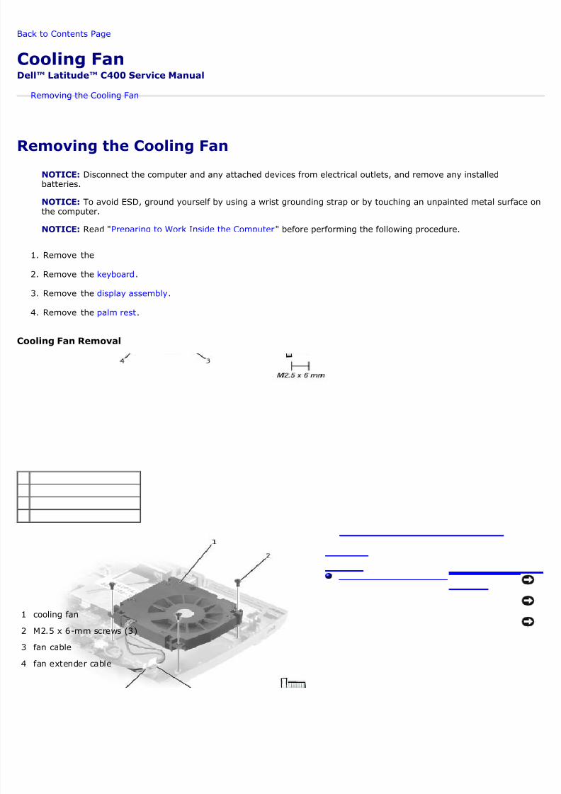
ooling Fan Removal
1 cooling fan
2 M2.5 x 6-mm screws (3)
3 fan cable
4 fan extender cable

8/13/2019 latitude-c400_Service Manual_en-us.pdf
http://slidepdf.com/reader/full/latitude-c400service-manualen-uspdf 27/41
5. Remove the fan cable from the fan extender cable that runs under the system board.
6. Remove the three M2.5 x 6-mm screws that secure the cooling fan.
7. Lift out the cooling fan.
ack to Contents Page
8/13/2019 latitude-c400_Service Manual_en-us.pdf
http://slidepdf.com/reader/full/latitude-c400service-manualen-uspdf 28/41
ack to Contents Page
Reserve BatteryDell™ Latitude™ C400 Service Manual
Removing the Reserve Battery
Replacing the Reserve Battery
Removing the Reserve Battery
NOTICE: The reserve battery provides power to the computer's RTC and NVRAM when the computer is turned off.Removing the battery causes the computer to lose the date and time information as well as all user-specifiedparameters in the BIOS. If possible, make a copy of this information before you remove the reserve battery.
NOTICE: Disconnect the computer and any attached devices from electrical outlets, and remove any installedbatteries.
NOTICE: To avoid ESD, ground yourself by using a wrist grounding strap or by touching an unpainted metal surfacethe computer.
NOTICE: Read "Preparing to Work Inside the Computer" before performing the following procedure.
1. Remove the hard drive.
2. Remove the keyboard.
3. Remove the display assembly.
4. Remove the palm rest.
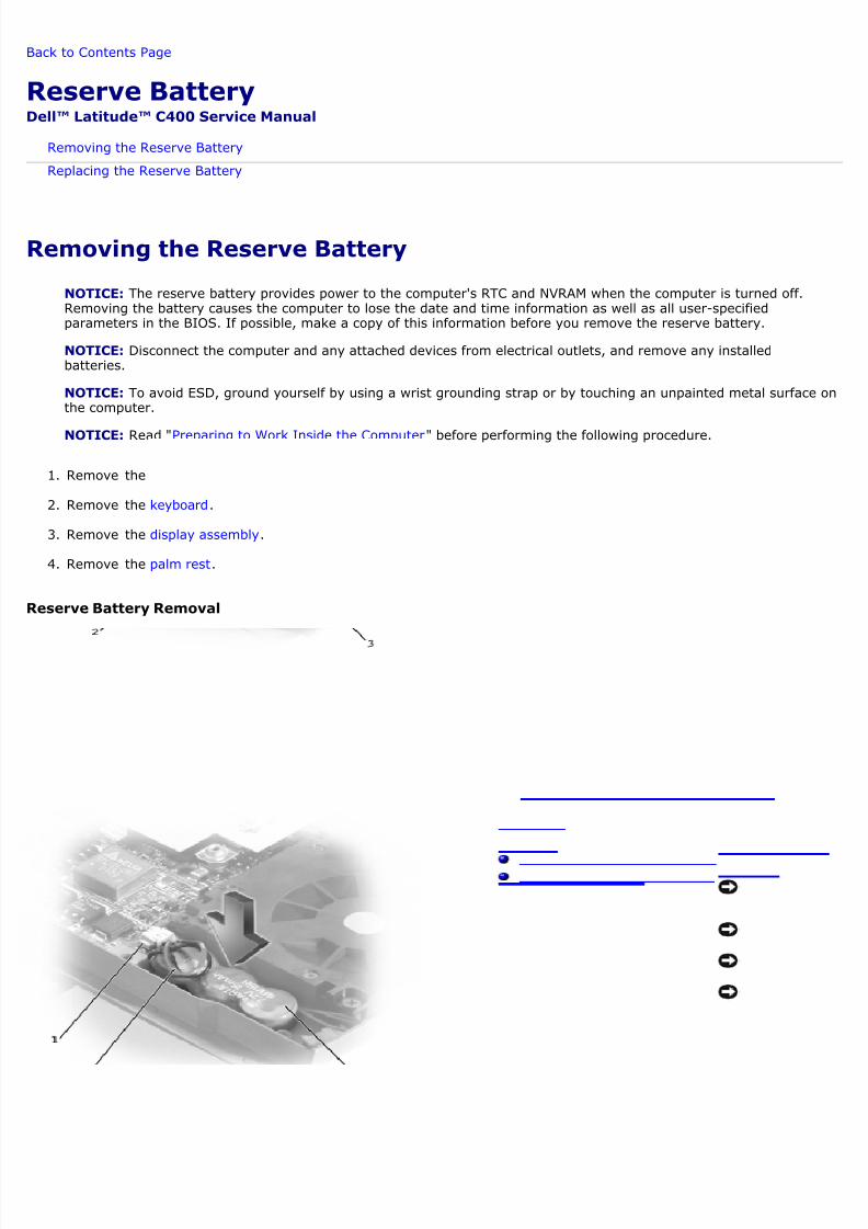
Reserve Battery Removal
8/13/2019 latitude-c400_Service Manual_en-us.pdf
http://slidepdf.com/reader/full/latitude-c400service-manualen-uspdf 29/41
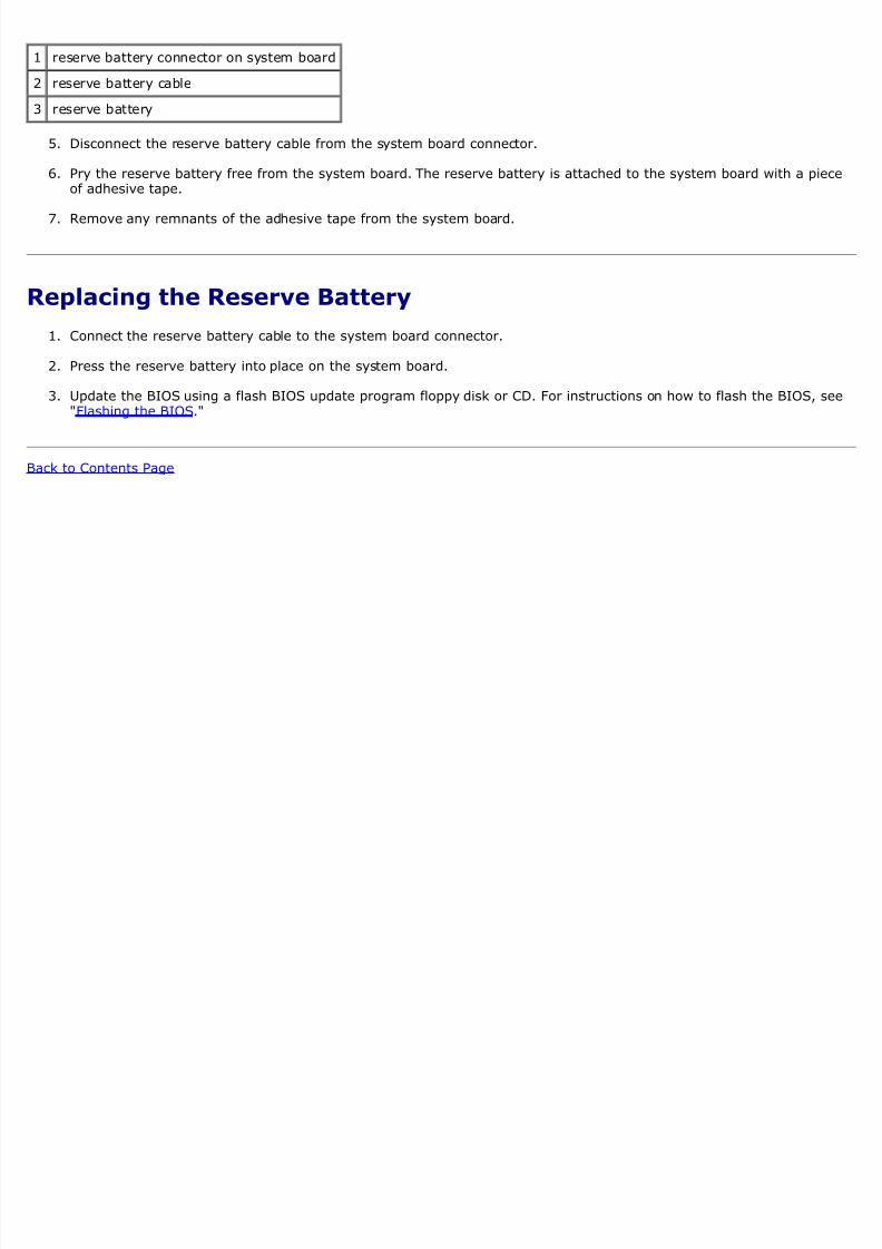
1 reserve battery connector on system board
2 reserve battery cable
3 reserve battery
5. Disconnect the reserve battery cable from the system board connector.
6. Pry the reserve battery free from the system board. The reserve battery is attached to the system board with a pieof adhesive tape.
7. Remove any remnants of the adhesive tape from the system board.
Replacing the Reserve Battery
1. Connect the reserve battery cable to the system board connector.
2. Press the reserve battery into place on the system board.
3. Update the BIOS using a flash BIOS update program floppy disk or CD. For instructions on how to flash the BIOS, s"Flashing the BIOS."
ack to Contents Page
8/13/2019 latitude-c400_Service Manual_en-us.pdf
http://slidepdf.com/reader/full/latitude-c400service-manualen-uspdf 30/41
ack to Contents Page
Flashing the BIOSDell™ Latitude™ C400 Service Manual
erform the following steps to update the BIOS:
1. Make sure that the AC adapter is plugged in and that the main battery is installed properly.
2. Turn on the computer. The following error message appears:
Syst em hardware f ai l ur es: #0010
St r i ke t he F1 key to shut down
3. Instead of pressing <F1>, insert the Flash BIOS update floppy disk or CD into the appropriate drive and press <F6and then press <F4>. The computer displays the following message on the screen:
Fai l ur e over r i de
Processor update f ai l ur e. Rel oad cur r ent BI OS
St ri ke the F1 key t o cont i nue, F2 t o run t he set up ut i l i t y.
4. Press <F1>. The computer continues to boot and updates the new BIOS.
5. Press <F2> to enter the system setup program and reset the boot sequence with the appropriate drive, if required
6. Press <ESC> to exit the system setup program.
7. Remove the Flash BIOS update floppy disk or CD from the drive and restart the computer.
ack to Contents Page
8/13/2019 latitude-c400_Service Manual_en-us.pdf
http://slidepdf.com/reader/full/latitude-c400service-manualen-uspdf 31/41
ack to Contents Page
Audio BoardDell™ Latitude™ C400 Service Manual
Removing the Audio Board
Replacing the Audio Board
Removing the Audio Board
NOTICE: Disconnect the computer and any attached devices from electrical outlets, and remove any installedbatteries.
NOTICE: To avoid ESD, ground yourself by using a wrist grounding strap or by touching an unpainted metal surfacethe computer.
NOTICE: Read "Preparing to Work Inside the Computer" before performing the following procedure.
1. Remove the hard drive.
2. Remove the keyboard.
3. Remove the display assembly.
4. Remove the palm rest.
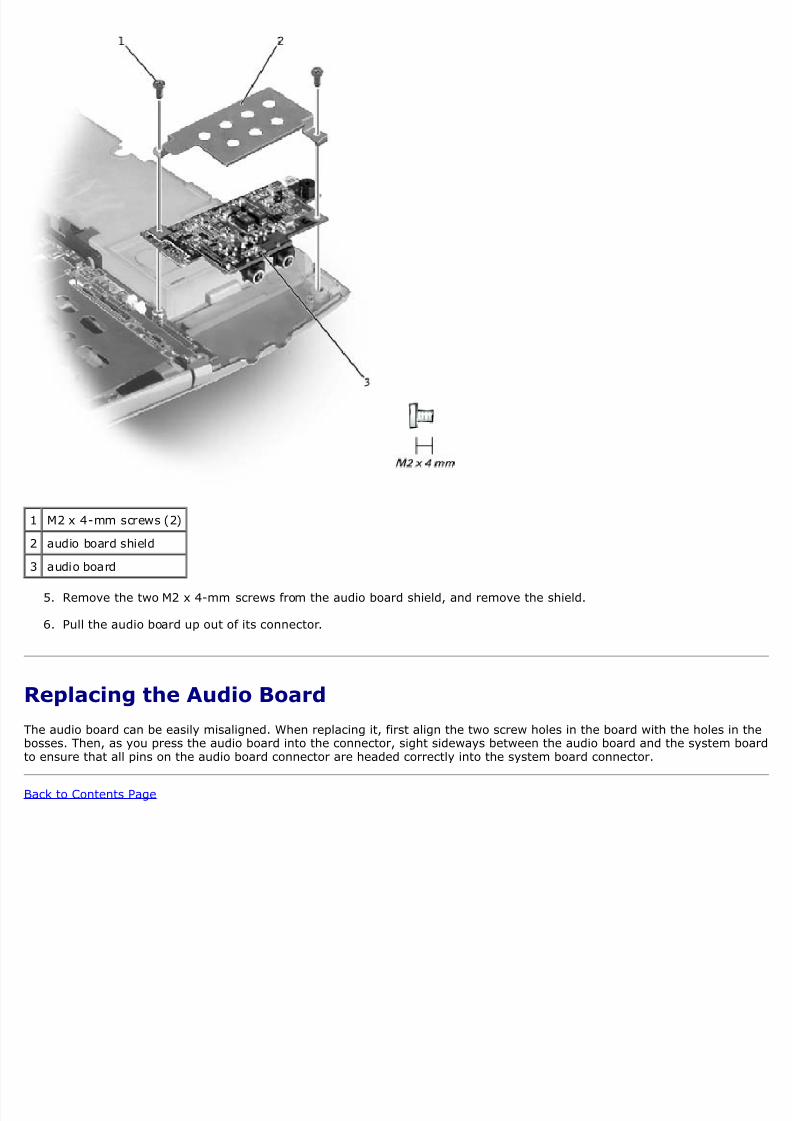
Audio Board Removal
8/13/2019 latitude-c400_Service Manual_en-us.pdf
http://slidepdf.com/reader/full/latitude-c400service-manualen-uspdf 32/41
1 M2 x 4-mm screws (2)
2 audio board shield
3 audio board
5. Remove the two M2 x 4-mm screws from the audio board shield, and remove the shield.
6. Pull the audio board up out of its connector.
Replacing the Audio Board
he audio board can be easily misaligned. When replacing it, first align the two screw holes in the board with the holes in osses. Then, as you press the audio board into the connector, sight sideways between the audio board and the system bo ensure that all pins on the audio board connector are headed correctly into the system board connector.
ack to Contents Page
8/13/2019 latitude-c400_Service Manual_en-us.pdf
http://slidepdf.com/reader/full/latitude-c400service-manualen-uspdf 33/41
ack to Contents Page
System BoardDell™ Latitude™ C400 Service Manual
Removing the System Board
Replacing the System Board
Removing the System Board
he system board's BIOS chip contains the service tag sequence, which is also visible on a barcode label on the bottom ofomputer. The replacement kit for the system board may include a CD that provides a utility for transferring the service taequence to the replacement system board.
NOTICE: Disconnect the computer and any attached devices from electrical outlets, and remove any installedbatteries.
NOTICE: To avoid ESD, ground yourself by using a wrist grounding strap or by touching an unpainted metal surfacethe computer.
NOTICE: Read "Preparing to Work Inside the Computer" before performing the following procedure.
1. Remove the PC Card or plastic blank, if present, from the PC Card slot.
2. Remove the hard drive.
3. Remove the keyboard.
4. Remove the display assembly.
5. Remove the palm rest.
6. Remove the wireless network adapter, if present.
7. Remove the modem daughter card, if present.
8. Remove all installed memory modules.
9. Remove the audio board.
ystem Board Removal
8/13/2019 latitude-c400_Service Manual_en-us.pdf
http://slidepdf.com/reader/full/latitude-c400service-manualen-uspdf 34/41
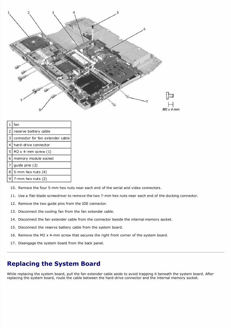
1 fan
2 reserve battery cable
3 connector for fan extender cable
4 hard-drive connector
5 M2 x 4-mm screw (1)
6 memory module socket
7 guide pins (2)
8 5-mm hex nuts (4)
9 7-mm hex nuts (2)
10. Remove the four 5-mm hex nuts near each end of the serial and video connectors.
11. Use a flat-blade screwdriver to remove the two 7-mm hex nuts near each end of the docking connector.
12. Remove the two guide pins from the IDE connector.
13. Disconnect the cooling fan from the fan extender cable.
14. Disconnect the fan extender cable from the connector beside the internal memory socket.
15. Disconnect the reserve battery cable from the system board.
16. Remove the M2 x 4-mm screw that secures the right front corner of the system board.
17. Disengage the system board from the back panel.
Replacing the System Board
While replacing the system board, pull the fan extender cable aside to avoid trapping it beneath the system board. Aftereplacing the system board, route the cable between the hard-drive connector and the internal memory socket.

8/13/2019 latitude-c400_Service Manual_en-us.pdf
http://slidepdf.com/reader/full/latitude-c400service-manualen-uspdf 35/41
fter you have replaced the system board, insert the floppy disk or CD that accompanied the replacement system board ihe appropriate drive, and turn on the computer. Follow the instructions on the screen.
NOTE: After replacing the system board, be sure to enter the computer's service tag sequence into the BIOS of thereplacement system board.
ack to Contents Page
8/13/2019 latitude-c400_Service Manual_en-us.pdf
http://slidepdf.com/reader/full/latitude-c400service-manualen-uspdf 36/41
ack to Contents Page
Battery LatchDell™ Latitude™ C400 Service Manual
Removing the Battery Latch
Replacing the Battery Latch
Removing the Battery Latch
NOTICE: Disconnect the computer and any attached devices from electrical outlets, and remove any installedbatteries.
NOTICE: To avoid ESD, ground yourself by using a wrist grounding strap or by touching an unpainted metal surfacethe computer.
NOTICE: Read "Preparing to Work Inside the Computer" before performing the following procedure.
1. Remove the PC Card or plastic blank, if present, from the PC Card slot.
2. Remove the hard drive.
3. Remove the keyboard.
4. Remove the display assembly.
5. Remove the palm rest.
6. Remove the wireless network adapter, if present.
7. Remove the modem daughter card, if present.
8. Remove all installed memory modules.
9. Remove the audio board.
10. Remove the system board.
attery Latch Removal
8/13/2019 latitude-c400_Service Manual_en-us.pdf
http://slidepdf.com/reader/full/latitude-c400service-manualen-uspdf 37/41
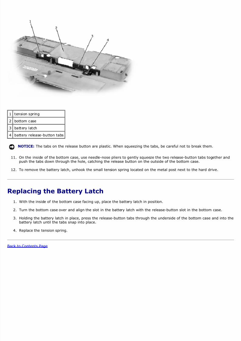
1 tension spring
2 bottom case
3 battery latch
4 battery release-button tabs
NOTICE: The tabs on the release button are plastic. When squeezing the tabs, be careful not to break them.
11. On the inside of the bottom case, use needle-nose pliers to gently squeeze the two release-button tabs together apush the tabs down through the hole, catching the release button on the outside of the bottom case.
12. To remove the battery latch, unhook the small tension spring located on the metal post next to the hard drive.
Replacing the Battery Latch
1. With the inside of the bottom case facing up, place the battery latch in position.
2. Turn the bottom case over and align the slot in the battery latch with the release-button slot in the bottom case.
3. Holding the battery latch in place, press the release-button tabs through the underside of the bottom case and intobattery latch until the tabs snap into place.
4. Replace the tension spring.
ack to Contents Page
8/13/2019 latitude-c400_Service Manual_en-us.pdf
http://slidepdf.com/reader/full/latitude-c400service-manualen-uspdf 38/41
ack to Contents Page
Pin Assignments for I/O ConnectorsDell™ Latitude™ C400 Service Manual
Serial Connector USB Connector
Docking Connector IDE Module Bay Connector
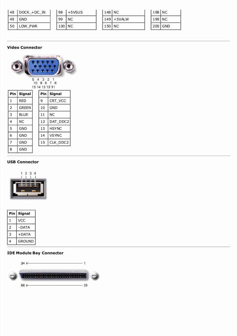
Video Connector
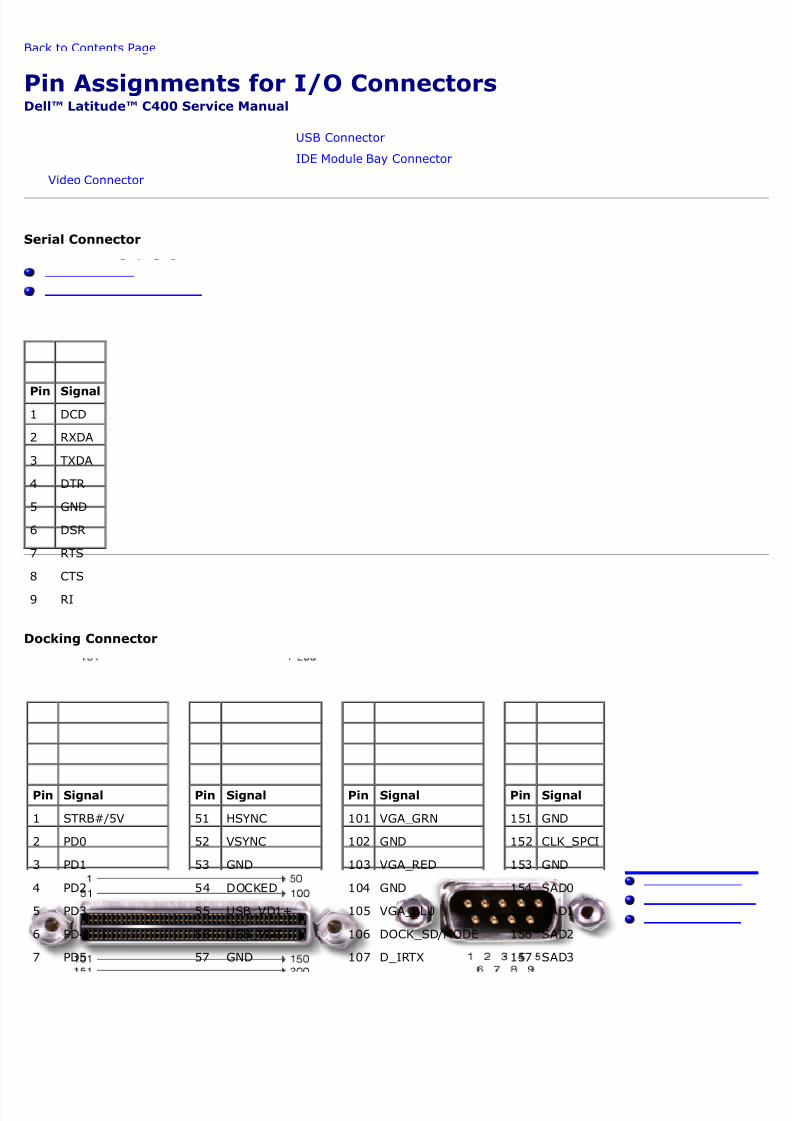
erial Connector
Pin Signal
1 DCD
2 RXDA
3 TXDA
4 DTR
5 GND
6 DSR
7 RTS
8 CTS
9 RI
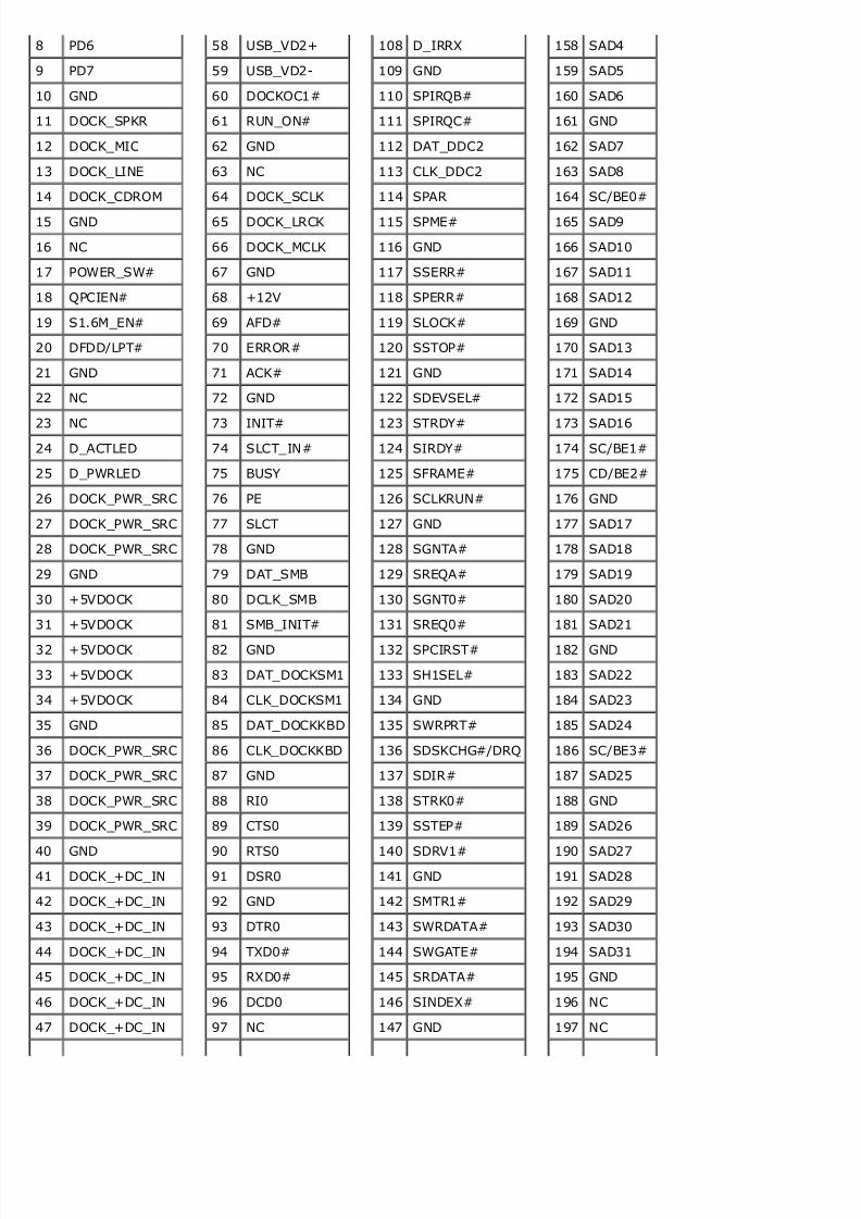
Docking Connector
Pin Signal
1 STRB#/5V
2 PD0
3 PD1
4 PD2
5 PD3
6 PD4
7 PD5
Pin Signal
51 HSYNC
52 VSYNC
53 GND
54 DOCKED
55 USB_VD1+
56 USB_VD1-
57 GND
Pin Signal
101 VGA_GRN
102 GND
103 VGA_RED
104 GND
105 VGA_BLU
106 DOCK_SD/MODE
107 D_IRTX
Pin Signal
151 GND
152 CLK_SPCI
153 GND
154 SAD0
155 SAD1
156 SAD2
157 SAD3
8/13/2019 latitude-c400_Service Manual_en-us.pdf
http://slidepdf.com/reader/full/latitude-c400service-manualen-uspdf 39/41
8 PD6
9 PD7
10 GND
11 DOCK_SPKR
12 DOCK_MIC
13 DOCK_LINE
14 DOCK_CDROM
15 GND
16 NC
17 POWER_SW#
18 QPCIEN#
19 S1.6M_EN#
20 DFDD/LPT#
21 GND
22 NC
23 NC
24 D_ACTLED
25 D_PWRLED
26 DOCK_PWR_SRC
27 DOCK_PWR_SRC
28 DOCK_PWR_SRC
29 GND
30 +5VDOCK
31 +5VDOCK
32 +5VDOCK
33 +5VDOCK
34 +5VDOCK
35 GND
36 DOCK_PWR_SRC
37 DOCK_PWR_SRC
38 DOCK_PWR_SRC
39 DOCK_PWR_SRC
40 GND
41 DOCK_+DC_IN
42 DOCK_+DC_IN
43 DOCK_+DC_IN
44 DOCK_+DC_IN
45 DOCK_+DC_IN
46 DOCK_+DC_IN
47 DOCK_+DC_IN
58 USB_VD2+
59 USB_VD2-
60 DOCKOC1#
61 RUN_ON#
62 GND
63 NC
64 DOCK_SCLK
65 DOCK_LRCK
66 DOCK_MCLK
67 GND
68 +12V
69 AFD#
70 ERROR#
71 ACK#
72 GND
73 INIT#
74 SLCT_IN#
75 BUSY
76 PE
77 SLCT
78 GND
79 DAT_SMB
80 DCLK_SMB
81 SMB_INIT#
82 GND
83 DAT_DOCKSM1
84 CLK_DOCKSM1
85 DAT_DOCKKBD
86 CLK_DOCKKBD
87 GND
88 RI0
89 CTS0
90 RTS0
91 DSR0
92 GND
93 DTR0
94 TXD0#
95 RXD0#
96 DCD0
97 NC
108 D_IRRX
109 GND
110 SPIRQB#
111 SPIRQC#
112 DAT_DDC2
113 CLK_DDC2
114 SPAR
115 SPME#
116 GND
117 SSERR#
118 SPERR#
119 SLOCK#
120 SSTOP#
121 GND
122 SDEVSEL#
123 STRDY#
124 SIRDY#
125 SFRAME#
126 SCLKRUN#
127 GND
128 SGNTA#
129 SREQA#
130 SGNT0#
131 SREQ0#
132 SPCIRST#
133 SH1SEL#
134 GND
135 SWRPRT#
136 SDSKCHG#/DRQ
137 SDIR#
138 STRK0#
139 SSTEP#
140 SDRV1#
141 GND
142 SMTR1#
143 SWRDATA#
144 SWGATE#
145 SRDATA#
146 SINDEX#
147 GND
158 SAD4
159 SAD5
160 SAD6
161 GND
162 SAD7
163 SAD8
164 SC/BE0#
165 SAD9
166 SAD10
167 SAD11
168 SAD12
169 GND
170 SAD13
171 SAD14
172 SAD15
173 SAD16
174 SC/BE1#
175 CD/BE2#
176 GND
177 SAD17
178 SAD18
179 SAD19
180 SAD20
181 SAD21
182 GND
183 SAD22
184 SAD23
185 SAD24
186 SC/BE3#
187 SAD25
188 GND
189 SAD26
190 SAD27
191 SAD28
192 SAD29
193 SAD30
194 SAD31
195 GND
196 NC
197 NC
8/13/2019 latitude-c400_Service Manual_en-us.pdf
http://slidepdf.com/reader/full/latitude-c400service-manualen-uspdf 40/41
48 DOCK_+DC_IN
49 GND
50 LOW_PWR
98 +5VSUS
99 NC
100 NC
148 NC
149 +5VALW
150 NC
198 NC
199 NC
200 GND
ideo Connector
Pin Signal
1 RED
2 GREEN
3 BLUE
4 NC
5 GND
6 GND
7 GND
8 GND
Pin Signal
9 CRT_VCC
10 GND
11 NC
12 DAT_DDC2
13 HSYNC
14 VSYNC
15 CLK_DDC2
SB Connector
Pin Signal
1 VCC
2 –DATA
3 +DATA
4 GROUND
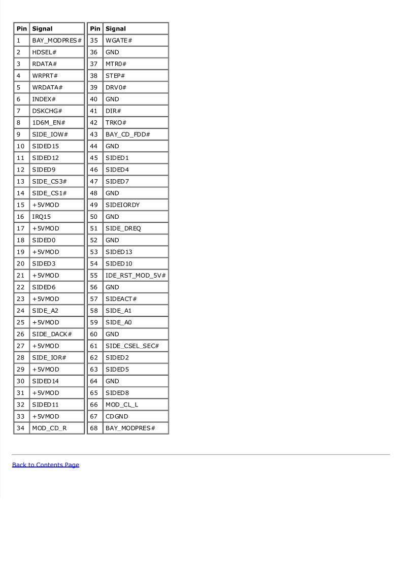
DE Module Bay Connector
8/13/2019 latitude-c400_Service Manual_en-us.pdf
http://slidepdf.com/reader/full/latitude-c400service-manualen-uspdf 41/41
Pin Signal
1 BAY_MODPRES#
2 HDSEL#
3 RDATA#
4 WRPRT#
5 WRDATA#
6 INDEX#
7 DSKCHG#
8 1D6M_EN#
9 SIDE_IOW#
10 SIDED15
11 SIDED12
12 SIDED9
13 SIDE_CS3#
14 SIDE_CS1#
15 +5VMOD
16 IRQ15
17 +5VMOD
18 SIDED0
19 +5VMOD
20 SIDED3
21 +5VMOD
22 SIDED6
23 +5VMOD
24 SIDE_A2
25 +5VMOD
26 SIDE_DACK#
27 +5VMOD
28 SIDE_IOR#
29 +5VMOD
30 SIDED14
31 +5VMOD
32 SIDED11
33 +5VMOD
34 MOD_CD_R
Pin Signal
35 WGATE#
36 GND
37 MTR0#
38 STEP#
39 DRV0#
40 GND
41 DIR#
42 TRKO#
43 BAY_CD_FDD#
44 GND
45 SIDED1
46 SIDED4
47 SIDED7
48 GND
49 SIDEIORDY
50 GND
51 SIDE_DREQ
52 GND
53 SIDED13
54 SIDED10
55 IDE_RST_MOD_5V#
56 GND
57 SIDEACT#
58 SIDE_A1
59 SIDE_A0
60 GND
61 SIDE_CSEL_SEC#
62 SIDED2
63 SIDED5
64 GND
65 SIDED8
66 MOD_CL_L
67 CDGND
68 BAY_MODPRES#
Recommended