70 TRANSPORTATION RESEARCH RECORD 1336
Lateral Subgrade Modulus of Sands for Deep Foundations
DANIEL 0. WONG
The common practice of designing laterally loaded deep foundations is either by means of the lateral sub grade modulus concept or by the lateral load tran fer method . The lateral subgrade modulu for sand is a function of several factors including deflection , wh.ich it elf is usually an unknown. The lateral load tran fer med10d is readily available to analyze laterally Loaded deep fo'undatioli by using p-y curves. However, p-y curves are complicated mathematical relations and by no means offer a simple repre entation of the pile-soil interaction. The concept of the equivalent subgrade modulus for sands, in which the nonlinear pile-soil characteristics are implicitly taken into account, i presented. Relationships of. equivalent subgrade modulu ver u dimensionless lateral load factor for sands are developed and a design procedure is proposed. Comparison f olution by the propo ed de ign procedure and the lateral load transfer method is favorable.
The design of laterally loaded deep foundation typically requires the prediction of lateral deflection and induced bending moment of the foundation elements under applied load . The analyses can be performed by means of the lateral subgrade modulus concept. The lateral subgrade modulus is a linear relationshjp of oi l pres ure and deflection . However, the lateral subgrade modulus i a function of depth for cohesionless soils (1). McClelland and Focht (2) also howed that soil responses to lateral loading are dependellt on depth and pi.le deflection. A representative value of the lateral subgrade modulus may be assumed for a particular problem (3). A more rational approach to analyzing laterally loaded piles is to model the oils by uncoupled , n nlinear load transfer functions widely known a p-y curve . A p-y relatio.nship is a mathematical repre entation of th oil reaction and the lateral piJ deflection per unit length ac a paJticular location along the pile . A linear subgrade modulu with re pect to depth can be obtained by an iterative procedure using p-y data (4). Numerical procedures using finite difference or finite element algorithms have been developed to incorporate the p-y criteria in the analyses of laterally loaded piles (5 ,6). However, such procedures require extensive numerical procedures such that the linear subgrade modulu method may be preferred in preliminary computations or for relatively imple design ca es. Furthermore a single subgrade modulu for a particular problem usually provide a better overall feeling or under ·rnnding of the pile- oil interaction than a eries of p-y curves. Attempts have been made in the pa l to develop a simplified method for analyses of laterally loaded piles (7). The work presented offers a unique subgrade modulus for ands de cribing the pile-soiJ interaction for a pecific laterally loaded pile condition.
McBride-Ratcliff and Associates , Inc., 7220 Langtry, Houston, Tex. 77040.
The development of the equivalent subgrade modul,u kcq for sands under lateral loads is described . The equivalent ubgrade modulus is a pile-soil relationship incorporating im
plicitly the effects of the lateral load and the nonlinearity of pile- oil interaction. A parametric study was conducted to develop the appropriate equjvalent ubgrade modulus by backcalculating with Broms's equation (3) using the required deflection obtained from a numerical model for the laterally loaded pile problem- COM 624 (6) . Such methodology wa used uccessfully to develop the equivalent ubgrade modulu for lateral1y loaded piles in clays (8). Among the parameters investigated in thi study are lateral load , pile stiffness and soi l properties. Boch submerged and above-water conditions are considered. The de ign curves of k.q versus the dimensionless lateral load factor for cohesionless soil · are subsequently developed and a simple design procedure i · propo ed. Solutions for ma~imum pile deflection and maximum bending moment for laterally loaded piles in sands can be readily solved with accuracy comparable with the load transfer method.
BROMS'S EQUATIONS AND NONDIMENSIONAL SOLUTIONS
Presented in this section are the brief synopses of Broms's equations and the nondimensional solutions for solving laterally loaded piles in sands.
Broms's Equations
Broms (3) stated that for piles with the dimensionles depth of embedment of ..,.,L larger than 4.0 , the magnitude of the lateral deflection at the ground surface i · unaffected by a change of the embedment length, L. ,, is defined as
(1)
where k i the coefficient of subgrade reaction, assumed to be a function of relative density of soil only, and EI is the bending tiffne s of the pile.
Terzaghi (1) has shown that the horizontal coefficient of subgrade reaction kh at depth Z, for a pile with diameter B, in sand can be found as
(2)

Wong
Broms recommended that the lateral deflection at the ground surface, y0 , for a free-head long pile (11L > 4.0) be calculated as
2.40P Yo = kfl·6( EJ)M
where P is the applied lateral load at the ground surface.
(3)
For a fully restrained long pile, where the slope at the pile head remains zero, the deflection at the ground surface is determined by
0.93P Yo = kfl·6(£J)0.4
Nondimensional Solutions
(4)
Nondimensional solutions for laterally loaded piles require an iterative procedure to achieve convergence of the relative stiffness factor, T, which is the reciprocal of 11 in Equation 1:
T = (Ellk)0•2 (5)
The lateral deflection, y, and bending moment, M, of the pile can be obtained from the following equations:
(6)
(7)
where A y and BY are deflection coefficients due to the applied lateral load P and the applied moment M, respectively, and Am and Bm are moment coefficients due to the applied lateral load P and the applied moment M, respectively.
Depending on the value of the maximum depth coefficient, Zmax , the deflection and mon:!er1l coefficients can be obtained at any depth along the pile. Coefficient charts are available in Matlock and Reese's paper (4). Zmax is defined as
L Z max = T (8)
In the absence of an applied moment at thl?. pile head, the maximum deflection and moment coefficients can be found in Table 1.
71
Using the maximum coefficients in Table 1, the maximum deflection and maximum moment of piles under the lateral loads can be calculated from Equations 6 and 7, respectively.
Both Broms's equations and the nondimensional solutions describe the soil resistance by a modulus k, which, as mentioned previously, is a function of the depth and magnitude of the lateral load. The estimation of the k value is usually a challenge to practicing engineers but is essential to the accuracy of the solution. This paper presents a representative k value, which implicitly accounts for the effects of pile depth, pile diameter, and the applied lateral loads, to be used directly in the Broms and nondimensional equations.
LOAD TRANSFER RELATIONSHIPS FOR SANDS
Nonlinear lateral load transfer relationships, termed p-y curves, are often used to represent the soil responses subjected to lateral loading. A brief description of four procedures to construct p-y curves for piles in sands , as presented by Murchison and O'Neill (9), is presented in the subsequent paragraphs. Details of the four procedures can be found in their respective references .
Procedure of Reese et al.
Reese et al. (10) introduced a p-y method based on the results of a series of field tests. A p-y curve constructed from this method consists of four segments as shown in Figure 1. The first segment is a linear relationship with a slope of kZ up to a point that can be determined by an empirical relationship, where Z is the depth of interest. k is a soil modulus and can be determined from the standard penetration test blow count. Correlations shown in Figures 2 and 3 are recommended. Figures 2 and 3 are modified by Murchison and O'Neill (9) from Gibbs and Holtz (11) and Meyer and Reese (12) , respectively. The second segment is a parabola and terminates at a deflection of B/60, where B is the diameter of the pile . The curve continues in a straight line with a slope empirically determined and terminates at a deflection of 3B/80 with soil resistance reaching an ultimate value , Pu· Pu remains unchanged as deflection increases for the fourth segment in the p-y curve . The ultimate soil resistance per unit of depth, Pu, can be calculated as the lesser value of Equations 9 and 10 and modified by an empirical parameter involving the pile, soil , and loading conditions.
Pu = ·yz[B(KP - K.) + ZKP tan <I> tan f3]
Pu = -yBZ[K~ + 2K0K~ tan<!> + tan<!> - K.]
(9)
(10)
TABLE 1 SUMMARY OF MAXIMUM DEFLECTION AND MOMENT COEFFICIENTS DUE TO LATERAL LOAD ONLY (4)
A A zm ...
Fr«·head Restrained-Head Free-head Reslnlned·ff•ad (Slope=O.O) (Slope•O.O)
10 2-435 0.820 0.772 0.930
4 2.445 0.829 0.767 0.930
3 2.723 0.968 0.704 0.970
2.2 4.011 1.268 0.557 1.060

72
p
Z:O
y
FIGURE 1 Characteristic shape of a family of p-y curves for procedure of Reese et al. (10).
where 'Y is the unit weight of soils and K. and KP are Rankine active and passive coefficient, respectively. K 0 is the at-rest earth pressure coefficient, <!> is the frictional angle, and f3 is determined as 45 + <j>/2.
Bogard and Matlock's Procedure
This method (13) called for a modification of the first method by simplifying the calculation of Pu and using nondimensional charts to generate p-y curves. Pu can be determined as the minimum of the values given in Equations 11 and 12.
100
TRANSPORTATION RESEARCH RECORD 1336
Pu (11)
Pu (12)
The parameters Cv C2 , and C3 are related to the angle of internal friction of sands. The p-y curves are subsequently constructed using normalized charts.
Scott's Procedure
Scott (14) idealized the p-y curve into two linear segments. The first straight line segment terminates at a resistance value Pk with a slope of kZ. pk can be determined from design curves of normalized resistance versus angle of internal friction; k can be found from the relationship presented in Figure 3. The second straight line segment starts with Pk with an empirically determined slope of kZ/4. There is no ultimate soil resistance value defined in this method.
Murchison and O'Neill Procedure
The p-y relationship characterized by this procedure (9) is a continuous hyperbolic tangent curve. This method is a reformulation of Parker's recommendation (15) on his experimental and analytical study of small diameter piles in sands. Murchison and O'Neill suggested that the characteristic p-y curve can be represented as
P = ~Putanh [ (A~~Jy J (13)
40 psi
-.... ' Cl)
80
NUMBERS ON CURVES
INDICATE EFFECTIVE
OVERBURDEN PRESSURE
OF SANOS AT DEPTH
~ 0 _, m
z .... z ;:)
0 0
~ 0 _, m
60
40
20
RELATIVE I VERY I DENSITY LOOSE LOOSE
iii 28° 29°
OF .. TEIEST
I 30°
I DENSE
38°
20 psi
psi
FIGURE 2 SPT blow count versus angle of friction and relative density of sands (9).

Wong
-u
VERY LOOS~ 300 LOOSE
250
200
.! 150
.K
100
50
MEDIUM DENSE DENSE
VERY DENSE
SANO BELOW THE WATER
TABLE
73
o._~~_,__...~~--i--.._~~~ ............. ~~-----._~__. 0 20 40 60 80 100
D, ("!.)
FIGURE 3 k versus relative density (9).
where Pu is the unmodified ultimate soil resistance found in Equations 9 and 10. 'TJ is taken as 1.5 for uniformly tapered piles and 1.0 for circular, prismatic piles. A is a factor related to the diameter of pile, B, and depth Z as
A = 3 - O.SZIB ~ 9 for static loading (14)
The shape of the p-y curve generated from this procedure is similar to that from the procedure of Reese et al. except that it is not a piecewise curve but a continuous analytical function.
PARAMETRIC STUDY
A parametric study was performed on hypothetical problems to determine a representative lateral subgrade modulus, called the equivalent lateral subgrade modulus (keq), under specific pile-soil conditions. The same methodology was successfully used to develop the lateral equivalent subgrade modulus for piles in clays (8) . The method involves calculating the lateral deflection of a hypothetical pile, y0 , under specific soil and loading conditions by employing a numerical computer solution COM624 (6). The equivalent lateral subgrade modulus,
keq' can lie determined by rewriting Equations 3 and 4 as follows:
keq 4.302 P 1
•67
for free-head pile (15) (El)o.61 y~61
l.eq o. 86 P1
·"' for restrained-head pile (16) (E/)0.61 Y!6'
where P is the applied lateral load and EI is the bending stiffness of pile.
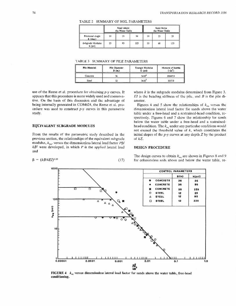
A wide range of sub grade modulus was selected to represent a full spectrum of soil parameters in this study. Table 2 summarizes the selected soil parameters for cohesionless soils above and below the water table. The pile parameters investigated in the study are given in Table 3.
To perform the required numerical analyses using COM624, the lateral pile-soil interaction is modeled by the p-y curves, which may be constructed by one of the four procedures described in previous sections. Murchison and O'Neill (9) concluded that their proposed procedure was the most accurate of all four procedures. However, the conclusion of accuracy was based on a small data base and the relative comparison of the four procedures. The recent design manual sponsored by the Federal Highway Administration (16) recommends the
74 TRANSPORTATION RESEARCH RECORD 1336
TABLE 2 SUMMARY OF SOIL PARAMETERS
Sand Above Sand Below the Water Table the Water Table
Frictional Angle 29 33 39 29 33 39 di ldeo.\
Subgrade Modulus 25 95 225 20 60 125 k (pci)
TABLE 3 SUMMARY OF PILE PARAMETERS
Piie Material Piie Diameter B (In.)
Concrete 36
Steel 12
use of the Reese et al. procedure for obtaining p-y curves. It appears that this procedure is more widely used and conservative. On the basis of this discussion and the advantage of being internally generated in COM624, the Reese et al. procedure was used to construct p-y curves in this parametric study.
EQUIVALENT SUBGRADE MODULUS
From the results of the parametric study described in the previous section, the relationships of the equivalent subgrade modulus, k0 q, versus the dimensionless lateral load factor P13/ kB2 were developed, in which P is the applied lateral load and
13 = (kB/4El)o.2s
·;:; ~ ... • ...
10
(17)
0
•
Young's Modulus Moment or Inertia E (psi) I (lo4)
3x10⁶ 80HOn
3x10⁷ 1017.9
where k is the subgrade modulus determined from Figure 3. EI is the bending stiffness of the pile, and B is the pile diameter.
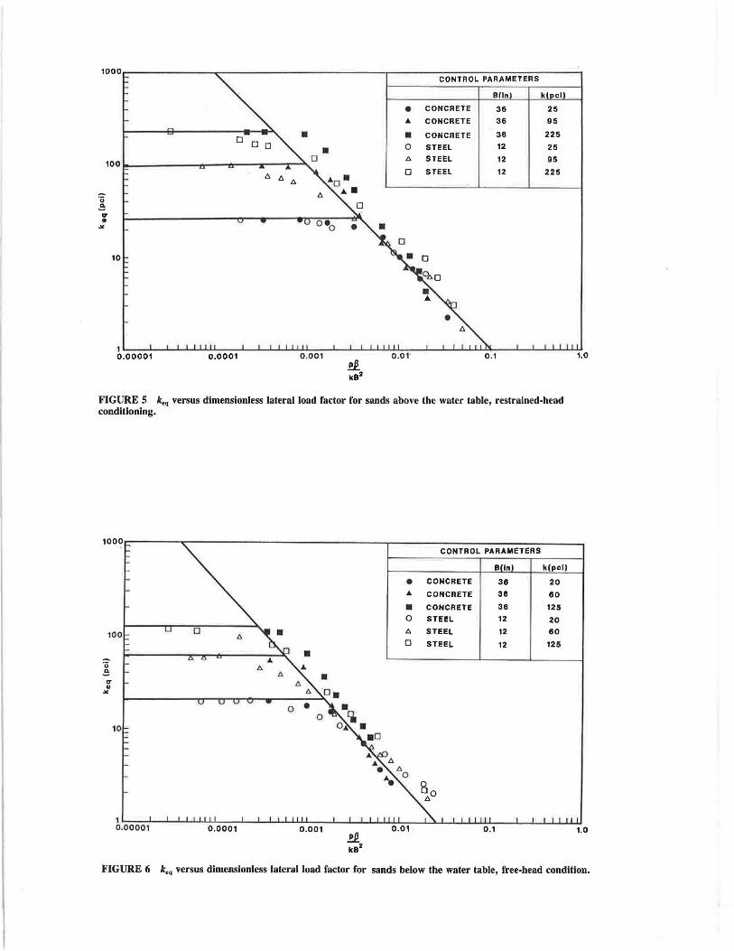
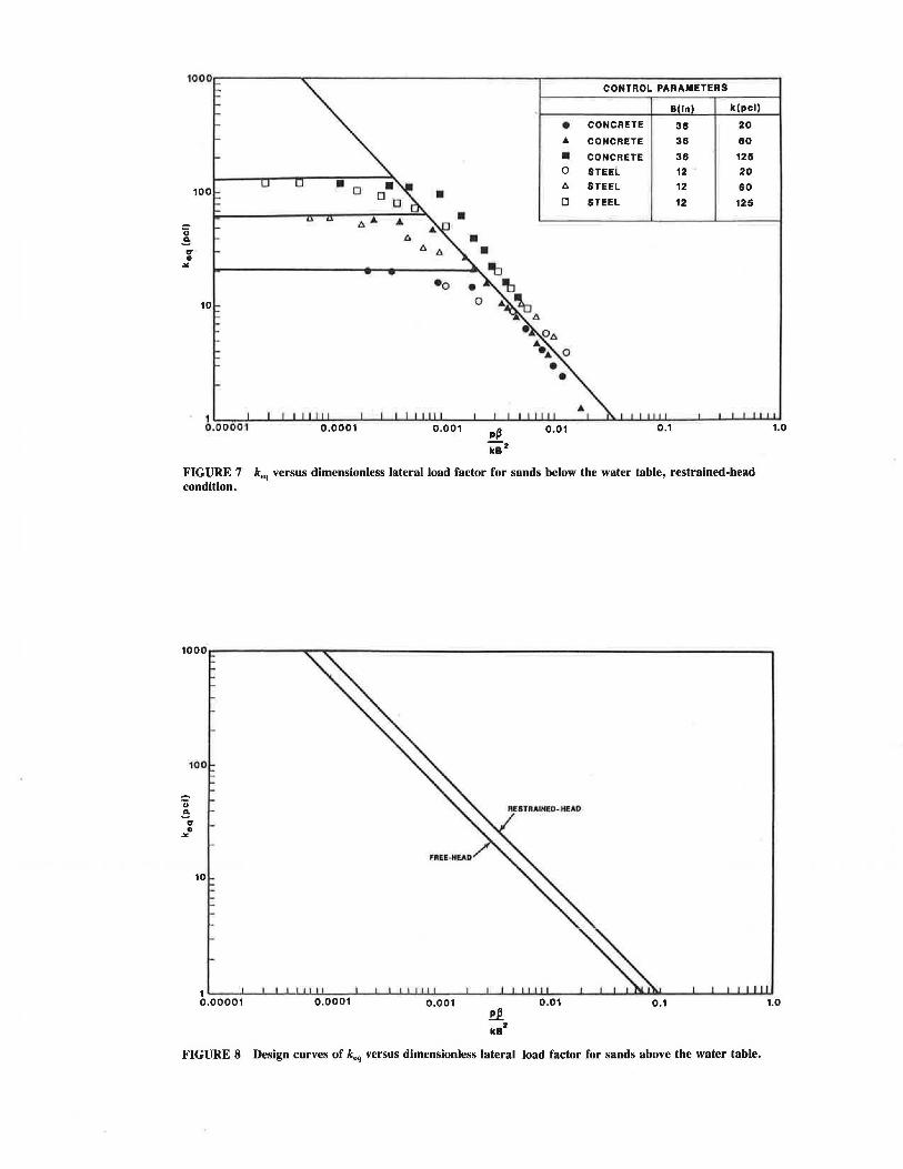
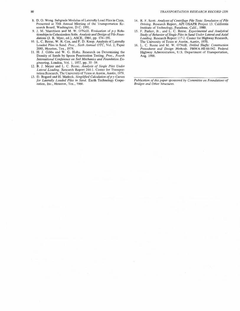
Figures 4 and 5 show the relationships of k0 q versus the dimensionless lateral load factor for sands above the water table under a free-head and a restrained-head condition, respectively. Figures 6 and 7 show the relationship for sands below the water table under a free-head and a restrainedhead condition. The k.q under any particular conditions would not exceed the threshold value of k, which constitutes the initial slopes of the p-y curves at any depth Z by the product of kZ.
DESIGN PROCEDURE
The design curves to obtain k0 q are shown in Figures 8 and 9 for cohesionless soils above and below the water table, re-
CONTROL PARAMETERS
Blln) k( cl)
• CONCRETE 311 25 ~ CONCRETE 36 95
• CONCRETE 311 225 0 STEEL 12 25 A STEEL 12 95
0 STEEL 12 225
1'-~.....L.-JL......JL......L....L..ILI.l..l...-~.....L.--l--l'-l....l.J..U.L-~...1..--1--L.....L.J....1..LJ.L-~...l..--L--L.....L...LJL..L.IJL...-~..L---L--L.....L. .............. 0.00001 0.0001 0.001 0.01 0.1
~ k8
FIGURE 4 k.q versus dimensionless lateral load factor for sands above the water table, free-head conditioning.
1.0
CONTROL PARAMETERS
Blln k cl
• CONCRETE 36 25 ... CONCRETE 36 95
• • CONCRETE 36 225 0 STEEL 12 25 /;. STEEL 12 95
0 STEEL 12 225
10
~~.o-0_0_0~1'---'--'-.L...L...l...L~o~.o-0-0-1_.___.__._._~~o~.~o-o-1__.~_,__,_.L..L~.u...~~'---'--'-~~~o~.1~___.~.._.._......._......_.~1.o
.!!! kB2
FIGURE 5 keq versus dimensionless lateral load factor for sands above the water table, restrained-head conditioning.
1000 CONTROL PARAMETERS
B In k(pcl)
• CONCRETE 36 20 ... CONCRETE 36 60
• CONCRETE 36 125 0 STEEL 12 20
100 0 /;. STEEL 12 60 0 STEEL 12 125
• '(j
..!!: .,. .. ""
~.~o~o~o-0~1'--~~ ..... .LL~OL.o-0_0_1~__.__.l-1...l..J.LLOL.o-0_1__Jl--..J.......L..L..l....L.J..U..~--l...i...L....L.LJ....LJ..OL.L1~......l.~.J....J....JW....L.LU1.o
!1. k8
2
FIGURE 6 k.q versus dimensionless lateral load factor for sands below the water table, free-head condition.
Ci .!!; ... ., ...
10
• D
A A
•
A
•o
p(j ka2
• ... • 0
A
D
0.01
CONTROL PARAMETERS
B In k(pcl)
CONCRETE 38 20
CONCRETE 38 80
CONCRETE 38 125
STEEL 12 20
STEEL 12 80
STEEL 12 125
FIGURE 7 k.q versus dimensionless lateral load factor for sands below the water table, restrained-head condition.
·u .e ... ., ...
1.0
1'--~....L.--'L.......1--'-.......... ..L..L.l.-~....L.--'--'--'-..L..L.U...L-~-'--'---"-'-..L..L.L.L.JL-~....._ ................ _._ ............ ~~-'---'--'-....L. ........ ~ 0.00001 0.0001 0.001 0.01 0.1 1.0
FIGURE 8 Design curves of k.q versus dimensionless lateral load factor for sands above the water table.

Wong 77
1L-~..L-...L..-'-L...L..L.U-'-~...L..-L-.1-.J-J..L..L....._~_.___._.......L...L.J...JL...L..L~---i-"-........ ._...~ .......... ~~'---'--'--'L....l....LU.J 0 .00001 0.0001 0 .001 !£. 0.01 0.1 1.0
k82
FIGURE 9 Design curves of k.q versus dimensionless lateral load factor for sands below the water table.
spectively. The horizontal lines in Figures 4 through 7 represent the threshold value of k for sands of variou relative densities. These lines are omitted in Figures 8 and 9, but the threshold values should be checked before a modulus is cho-en from the design curves. The checking mechanism will be
further discu ed in the following parngraph. A simple design procedure is propo ed to analyze laterally loaded piles in sands as follow :
1. haracterize the subsurface soil with a threshold subgrade modulu k, using the relationships presented in Figures 2 and 3.
2. Obtain coefficient J3 using Equation 17. 3. Calculate the dimen. ionless lateral load factor, PJ3/k82•
4. Determine the equivalent subgrade modulu , k.," from either Figure 8 or Figure 9. Depending on given subsurface and boundary conditions, check keq ~ k. If keq > k, use keq = k .
5. Calculate the maximum deflection of pile from Equations 3 or 4 by sub tituting k.q into k.
6. Determine the maximum moment from Equation 7 with all the necessary parameters obtained from Table 1 and Equation 5.
The nondimensional equation (Equation 6) can also be used to determine the maximum deflection of the p.ile by using the equivalent modulus k.q· However , only Brom ' equations (Equation 3 or 4) are considered for the ubsequenl sections of this paper.
This paragraph demonstrates the simplicity of the proposed design procedure by following Step 1 to 6 to olve an example problem. Given a pipe pile of 20-in. OD and % in. in wall
thickness driven into submerged sands (<!> = 30 degrees), k in Step 1 can be found in Figures 2 and 3 as 30 pci. Obtain J3 in Equation 17 as 8.186 x 10 - 3 in. - 1 using E of 3 x 10⁷
psi and I of 1,113.5 in. 4 Determine PJ3/kB2 for a lateral load P of 15 kips as O.Dl. Obtain a keq of about 2.8 pci from Figure 9. The maximum deflection and maximum moment are found to be 1.20 in. and 1.2 x 106 in.-lb using Equations 3 and 7, respectively, for free-head conditions.
To examine the effectiveness of the proposed design procedure, a study was conducted to compare results obtained by computer analyses using COM624 and by following the proposed procedure. Three cases were established for the comparison study: (a) steel pipe pile 20 in. in diameter and % in. in wall thickness driven in subrrierged sands and loaded laterally under free-head condition; (b) 24-in.-diameter drilled pier, dry sands, and restrained-bead condition; and (c) 48-in .-diameter drilled pier, ubmerged sand , and free-head condition. Table 4 summarizes the important parameters for these three cases. Figures 10 and 11 compare the maximum deflections and maximum moments, respectively, by COM624 and the proposed design method. The comparisons indicate a less than 10 p rcent discrepancy in results within the range of variou controlled parameters used in this study.
CONCLUSIONS
The relationships of equivalent subgrade modulus and dimensionless lateral load factor are established for laterally loaded piles in sands above and below the water table. A simple design procedure using the concept of the equivalent sub grade modulus is propo ed lo find the maximum deflection

TABLE 4 PARAMETERS FOR COMPARISON STUDY
Case Pile Piie Diameter Pile-Head Frlctlonal Soll Materlul 8 (In.) Condition Angle (deg.) Condllloo
A Steel 20• Free 30 Submerged
B Concrete 24 Restrained 35 Dry
c Concrete 48 Free 36 Submerged
• with 3/8 in. Wi.Jll lhickncss
PREDICTED BY COM624
1.2 PREDICTED BY THE PROPOSED DESIGN PROCEDURE
1.0 '"":' CASE A .!:
z 0 I-0 0.8 w ..I LL w Q
w ::! a.. 0.6 s ~ s )( o(
:I 0 .4
0.2
o'i/....::::::::=:i::::.:::::::=:=~-~~-'-~~-'-~~---'-~~---'~~~"--~---' 0 10 20 30 40 so 60 70 80
LATERAL LOAD AT PILE HEAD (KIPS)
FIGURE 10 Comparison of maximum deflections by COM624 and proposed method.

Wong 79
0 .5
8
PREDICTED BV COM62~
10
PREDICTED BV THE PROPOSED
DESIGN PROCEDURE
.. ~ '
.~
"' 0 8 ~
"' .... z w :I 0 :I 6
:I :::> ! )(
c(
:I 4
2
20 40 60 80 100
LATERAL LOAD AT PILE HEAD (KIPS)
FIGURE 11 Comparison of maximum moments by COM624 and proposed method.
and maximum moment for practical problems. A comparison study indicated that the results obtained by the proposed procedure compared well with those determined by the computer using numerical solution COM624.
LIMIT A TIO NS
The proposed equivalent lateral subgrade modulus and the design procedures were developed on the basis of the range of controlled parameters outlined in Tables 2 and 3. The findings of this study are only applicable for cohesion less soils . Similar results and procedures for cohesive soils can be found in a companion paper (8) . Potential users of the proposed design curves and procedures are urged to recognize all the limitations.
ACKNOWLEDGMENTS
The author would like to thank all the reviewers who provided many useful comments to this paper .
REFERENCES
1. K. Terzaghi. Evaluation of Coefficients of Subgrade Reaction. Oeoteclmiq11e, Institut ion of Civil Engineers, Vol. 5, London , 1955, pp. 297-326.
2. B. McClelland and J. A . Focht, Jr. Soil Modulus of Laterally Loaded Piles. Transactions, ASCE, Vol. 123, 1958, pp. 1.049-1086.
3. B. B. Broms. Lateral Resistance of Piles in Cohesionless Soils . Journal of the Soil Mech(lnics and Foundations Division , Vol. 90, No. SM3, 1964, pp. 123-156.
4. H. Mmlock and L. C. Reese. Generalized Solutions fo r Laterally Loaded Piles. Journal of the Soil Mechanics and Fo1111dations DMsion , Paper 2626, Vol. 86, No. SMS, 1960, pp. 63- 91.
5. H. Mal'lock and T. A. Haliburton. A Program for Finite· Element Solwio11 of Beam-Co/1111111s on Nonlinear Support . Austin, Tex., 1964.
6. L. C. Reese and W. R. Sullivan. Docwne111a1ion of Computer Program OM 624, Georecl111ica/ Engineering Software SSB0-1. Geotechnical Engineering Center Titc University of Texas at Austin , Austin, L97S, pp. 663-649.
7. L. T . Evan , J r., and J. M. Duncan. Simplified A 11alysi of Latert1/ly Loaded Piles . Report UCBfET/82-04. University of California at Berkeley, Berkeley, 1982.
80
8. D. 0. Wong. Subgrade Modulus of Laterally Load Piles in Clays. Presented at 70th Annual Meeting of the Transportation Research Board, Washington, D.C. 1991.
9. J. M. Murchison and M. W. O'Neill. Evaluation of p-y Relationships in Cohesionless Soils. A nalysis and Design of Pile Formdalions (J . R. Myer, ed .) , ASCE, 19 , pp. 174- 191.
10. L. . Reese, W. R. Cox , and F. D . Koop. Analy is of Laterally Loaded Piles in Sand. Proc., Sixth Annual OTC, Vol. 2, Paper 2080, Houston, Tex., 1974.
11. H . J. Gibbs and W. G. Holtz. Research on Determining the Density of Sands by poon Penetration Testing. Proc. Fourth 111temational Conference 011 oil Mechanics and Fowulation Engineering, London, Vol. 1, 1957, pp. 35-59.
12. B. J. Meyer and L. C. Reese. Analysis of Single Piles Under Lateral Loading. Research Report 244-1. Center for Transportation Research, The University of Texas at Austin, Austin, 1979.
13. D . Bogard and H. Matlock. Simplified Calculation of p-y urves for L111erally Loaded Piles in Sand. Earth Technology orporation, Inc., Houston, Tex., 1980.
TRANSPORTATION RESEARCH RECORD 1336
14. R. F. Scott. Analyses of Centrifuge Pile Tests: Simulation of Pile Driving. Research Report, API 0 APR Project 13. California Institute of Technology, Pasadena, Calif. , 1980.
15. F. Parker, Jr., and L. C. Reese. Experimental and Analytical Study of Behavior of Si11gle Piles in Sand Under Lateral and Axial Loading. Research Report 117-2. Center for Highway Re earch, The University of Texas at Austin, Austin, 1970.
16. L. C. Reese and M. W. O'Neill. Drilled Shafts: Construction Procedures and Design Methods. FHWA-HI-88-042. Federal Highway Administration, U.S. Department of Transportation, Aug. 1988.
Publication of this paper sponsored by Commillee on Foundations of Bridges and Other Structures.
Recommended