LAT-TD-04618 1
GLAST LAT Project
Tracker Inner Shipping ContainerTracker Inner Shipping Container
Analysis and Test ResultsAnalysis and Test Results
Tracker Inner Shipping ContainerTracker Inner Shipping Container
Analysis and Test ResultsAnalysis and Test Results
August 20, 2003
Michael OpieMichael Opie
LAT-TD-04618 2
GLAST LAT Project
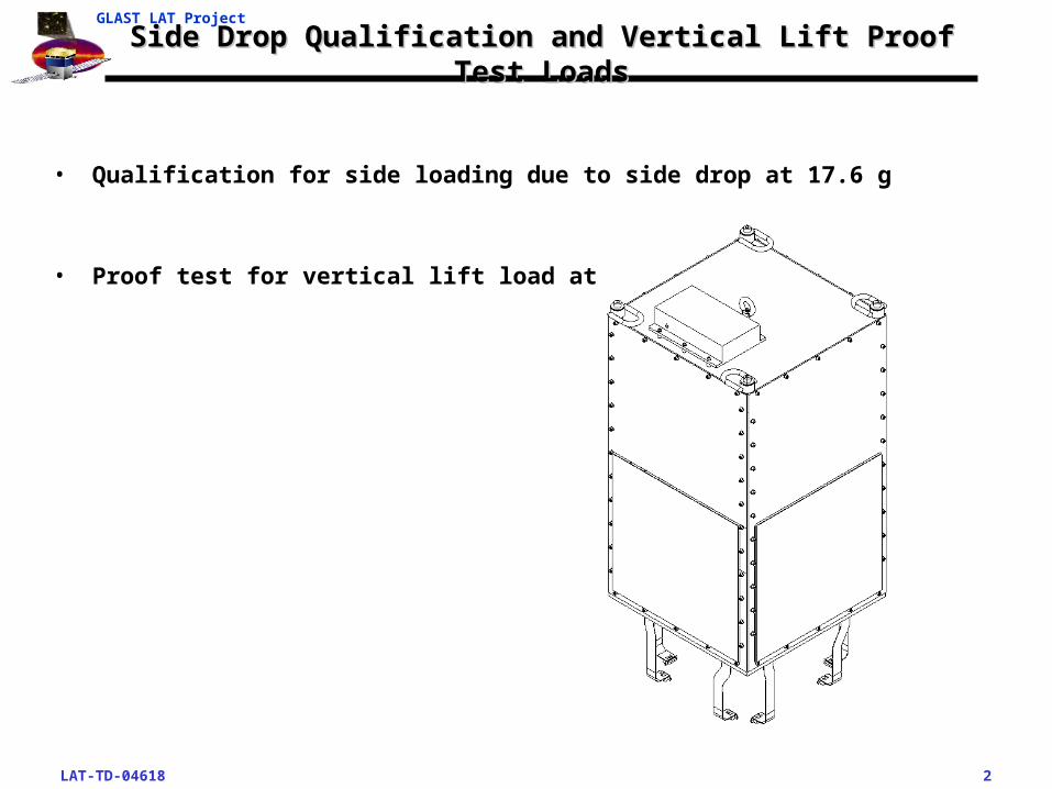
Side Drop Qualification and Vertical Lift Proof Test LoadsSide Drop Qualification and Vertical Lift Proof Test Loads
• Qualification for side loading due to side drop at 17.6 g
• Proof test for vertical lift load at 2g
LAT-TD-04618 3
GLAST LAT Project
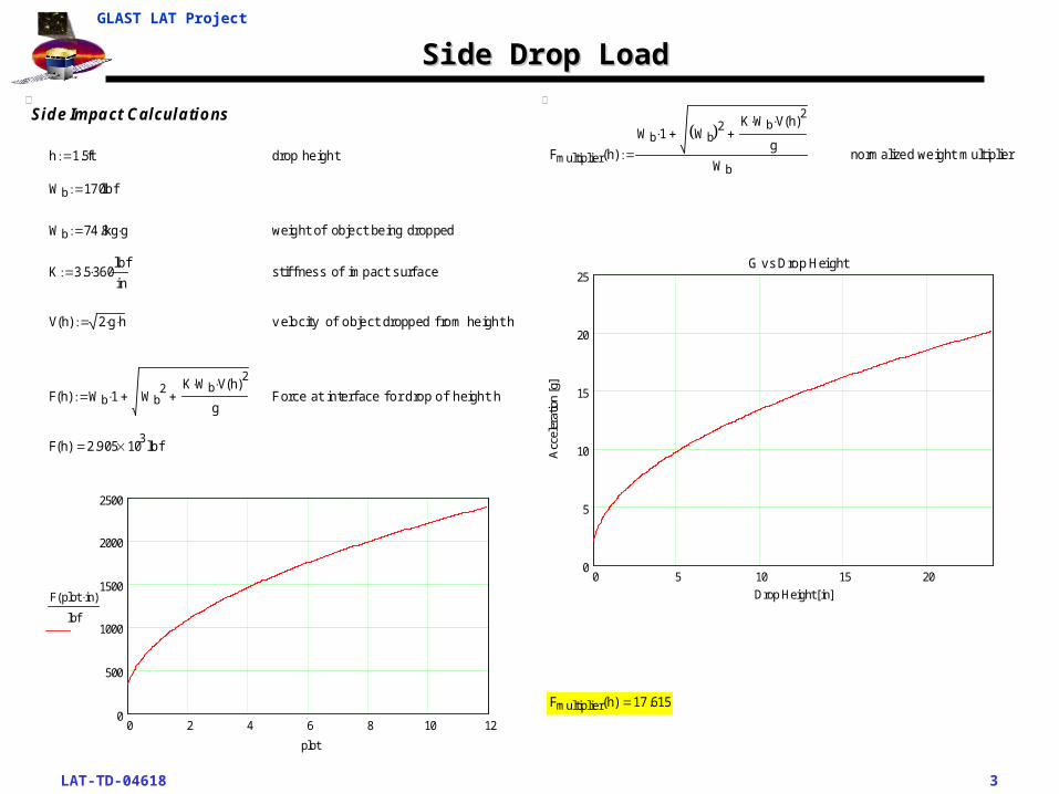
Side Drop LoadSide Drop Load
Side Impact Calcula tions
h 1.5ft drop height
Wb 170lbf
Wb 74.8kg g weight of object being dropped
K 3.5 360lb f
in st if f ness of impact surf ace
V h( ) 2 g h v elocity of object dropped f rom height h
F h( ) Wb 1 Wb2 K Wb V h( )
2
g Force at interf ace f or drop of height h
F h( ) 2.905 103 lb f
0 2 4 6 8 10 120
500
1000
1500
2000
2500
F plot in( )
lbf
plot
Fmultiplier h( )
Wb 1 Wb 2K Wb V h( )
2
g
Wb normalized weight mult iplier
0 5 10 15 200
5
10
15
20
25G vs Drop Height
Drop Height [in]
Acc
eler
atio
n [g
]
Fmultiplier h( ) 17 .615
LAT-TD-04618 4
GLAST LAT Project
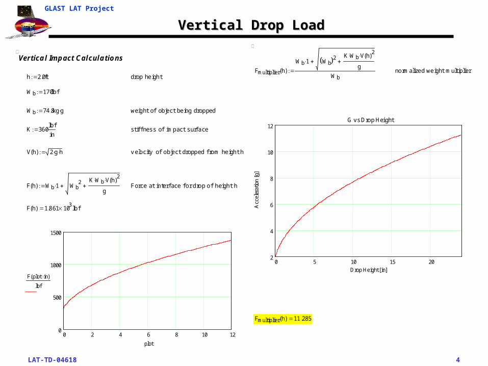
Vertical Drop LoadVertical Drop Load
Vertica l Impact Calcula tions
h 2.0ft drop height
Wb 170lbf
Wb 74 .8kg g weight of object being dropped
K 360lbf
in st if f ness of impact surf ace
V h( ) 2 g h v elocity of object dropped f rom height h
F h( ) Wb 1 Wb2 K Wb V h( )
2
g Force at interf ace f or drop of height h
F h( ) 1.861 103 lb f
0 2 4 6 8 10 120
500
1000
1500
F plot in( )
lbf
plot
Fmultiplier h( )
Wb 1 Wb 2 K Wb V h( )2
g
Wb normalized weight mult iplier
0 5 10 15 202
4
6
8
10
12G vs Drop Height
Drop Height [in]
Acc
eler
atio
n [g
]
Fmultiplier h( ) 11 .285
LAT-TD-04618 5
GLAST LAT Project
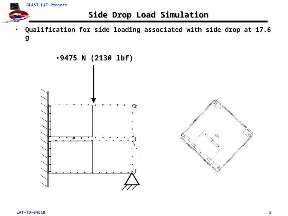
Side Drop Load SimulationSide Drop Load Simulation
• Qualification for side loading associated with side drop at 17.6 g
•9475 N (2130 lbf)
LAT-TD-04618 6
GLAST LAT Project
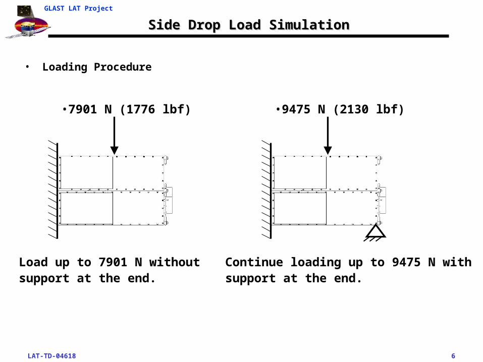
Side Drop Load SimulationSide Drop Load Simulation
• Loading Procedure
•7901 N (1776 lbf) •9475 N (2130 lbf)
Load up to 7901 N without support at the end.
Continue loading up to 9475 N with support at the end.
LAT-TD-04618 7
GLAST LAT Project
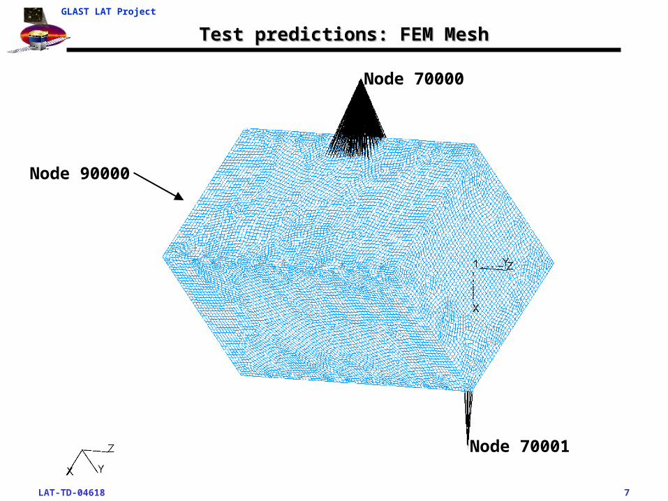
Test predictions: FEM MeshTest predictions: FEM Mesh
Node 70000
Node 70001
Node 90000
LAT-TD-04618 8
GLAST LAT Project
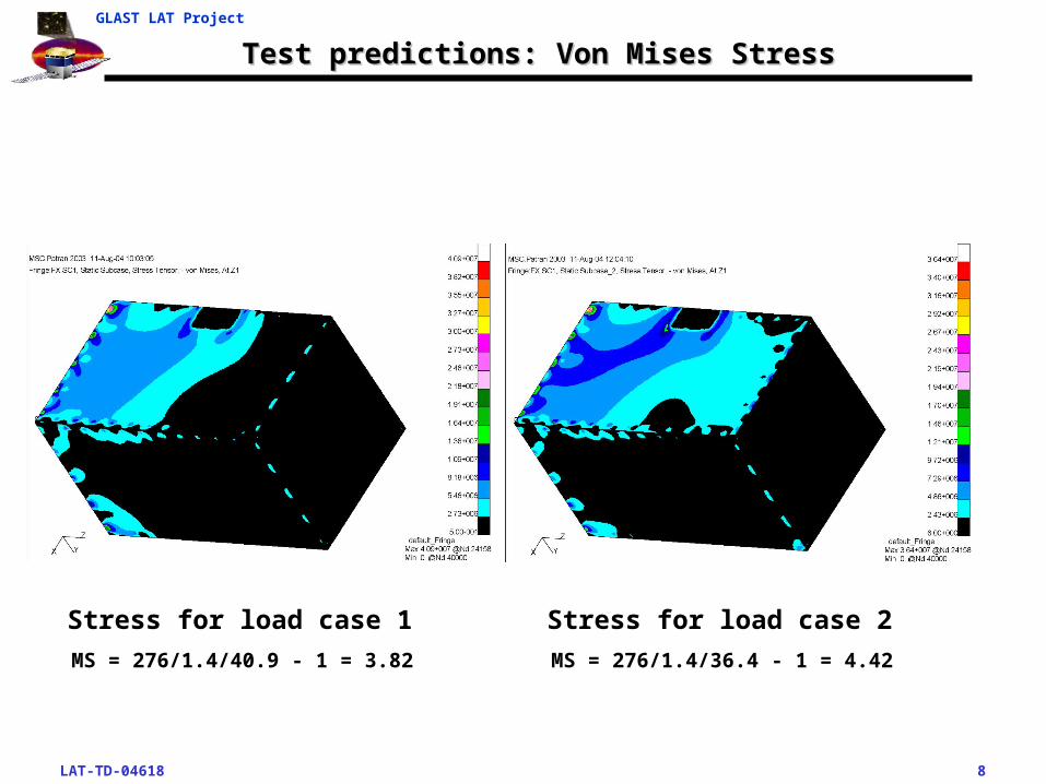
Test predictions: Von Mises StressTest predictions: Von Mises Stress
Stress for load case 2Stress for load case 1
MS = 276/1.4/40.9 - 1 = 3.82 MS = 276/1.4/36.4 - 1 = 4.42
LAT-TD-04618 9
GLAST LAT Project
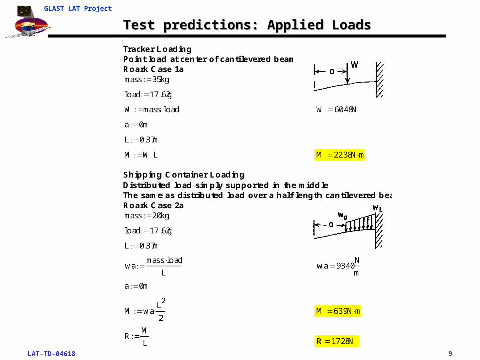
Test predictions: Applied LoadsTest predictions: Applied Loads
R 1728NRM
L
M 639N mM waL
2
2
a 0m
wa 9340N
mwa
mass loadL
L 0.37m
load 17 .62g
mass 20kg
Shipping Container LoadingDistributed load simply supported in the middleThe same as distributed load over a half length cantilevered beamRoark Case 2a
M 2238N mM W L
L 0.37m
a 0m
W 6048NW mass load
load 17 .62g
mass 35kg
Tracker LoadingPoint load at center of canti levered beamRoark Case 1a
LAT-TD-04618 10
GLAST LAT Project
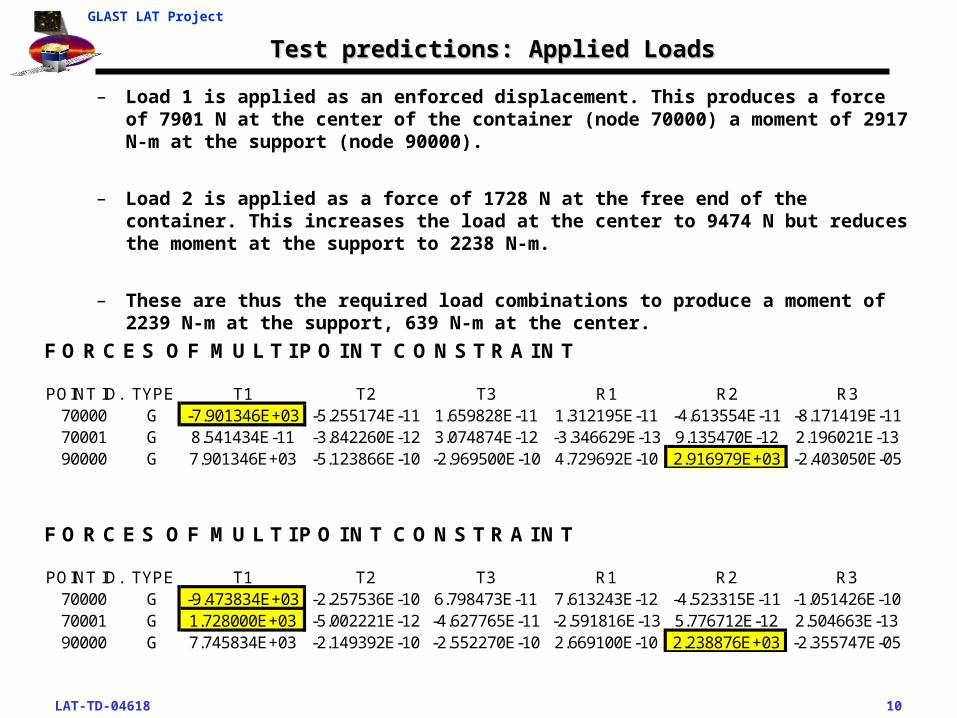
Test predictions: Applied LoadsTest predictions: Applied Loads
– Load 1 is applied as an enforced displacement. This produces a force of 7901 N at the center of the container (node 70000) a moment of 2917 N-m at the support (node 90000).
– Load 2 is applied as a force of 1728 N at the free end of the container. This increases the load at the center to 9474 N but reduces the moment at the support to 2238 N-m.
– These are thus the required load combinations to produce a moment of 2239 N-m at the support, 639 N-m at the center.
F O R C E S O F M U L T I P O I N T C O N S T R A I N T
POINT ID. TYPE T1 T2 T3 R1 R2 R370000 G -9.473834E+03 -2.257536E-10 6.798473E-11 7.613243E-12 -4.523315E-11 -1.051426E-1070001 G 1.728000E+03 -5.002221E-12 -4.627765E-11 -2.591816E-13 5.776712E-12 2.504663E-1390000 G 7.745834E+03 -2.149392E-10 -2.552270E-10 2.669100E-10 2.238876E+03 -2.355747E-05
F O R C E S O F M U L T I P O I N T C O N S T R A I N T
POINT ID. TYPE T1 T2 T3 R1 R2 R370000 G -7.901346E+03 -5.255174E-11 1.659828E-11 1.312195E-11 -4.613554E-11 -8.171419E-1170001 G 8.541434E-11 -3.842260E-12 3.074874E-12 -3.346629E-13 9.135470E-12 2.196021E-1390000 G 7.901346E+03 -5.123866E-10 -2.969500E-10 4.729692E-10 2.916979E+03 -2.403050E-05

LAT-TD-04618 11
GLAST LAT Project
Margins of Safety – Side Load LC 1Margins of Safety – Side Load LC 1
As F(y) F(u) F(y) F(u) Preload Torque Preload Load Bolt Friction SF(y) SF(u)mm^2 [MPa] [MPa] [N] [N] % of Yield [N-m] [N] [N] Efficientcy Coefficient14.9 344.7 689.5 5149 10299 65.0% 3.35 3347 8 1.00 0.15 2 319.6 189.585 379.225 3722 7446 0 2036
Bolt Interaction Helicoil Helicoil Plate Edge E/D Shear Shear MS Bearing Bearing MSMargin Fu Margin Thickness Distance Tearout Allowable Shear Allowable Bearing
[N] [mm] [mm] [MPa] [MPa] [MPa] [MPa] [MPa] [MPa]0.01 15791 0.57 3.18 12 2.4 26.7 186.2 1.33 128.1 606.7 0.580.56
Mass G-Loading Shear Load Axial Load[kg] [-] [N] [N]
74.80 17.62 2036 8
Part Description Material Load Case Failure Mode D dmm mm
LAT-DS-03949 TKR Inner Ship Assy 18-8 SS Mass = 74.8 Kg Tension 5.0 4.4DIN912-A2 M5 Soc Hd Cap Scr 100 ksi Ultimate 17.615G Side Load Shear 5.0 4.4

LAT-TD-04618 12
GLAST LAT Project
Margins of Safety – Side Load LC 2Margins of Safety – Side Load LC 2
Mass G-Loading Shear Load Axial Load[kg] [-] [N] [N]
74.80 17.62 1806 8
Part Description Material Load Case Failure Mode D dmm mm
LAT-DS-03949 TKR Inner Ship Assy 18-8 SS Mass = 74.8 Kg Tension 5.0 4.4DIN912-A2 M5 Soc Hd Cap Scr 100 ksi Ultimate 17.615G Side Load Shear 5.0 4.4
As F(y) F(u) F(y) F(u) Preload Torque Preload Load Bolt Friction SF(y) SF(u)mm^2 [MPa] [MPa] [N] [N] % of Yield [N-m] [N] [N] Efficientcy Coefficient14.9 344.7 689.5 5149 10299 65.0% 3.35 3347 8 1.00 0.15 2 319.6 189.585 379.225 3722 7446 0 1806
Bolt Interaction Helicoil Helicoil Plate Edge E/D Shear Shear MS Bearing Bearing MSMargin Fu Margin Thickness Distance Tearout Allowable Shear Allowable Bearing
[N] [mm] [mm] [MPa] [MPa] [MPa] [MPa] [MPa] [MPa]0.19 15791 0.57 3.18 12 2.4 23.7 186.2 1.62 113.6 606.7 0.780.83
LAT-TD-04618 13
GLAST LAT Project
Vertical Lift Load Proof TestVertical Lift Load Proof Test
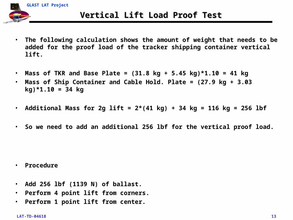
• The following calculation shows the amount of weight that needs to be added for the proof load of the tracker shipping container vertical lift.
• Mass of TKR and Base Plate = (31.8 kg + 5.45 kg)*1.10 = 41 kg • Mass of Ship Container and Cable Hold. Plate = (27.9 kg + 3.03 kg)*1.10 = 34 kg
• Additional Mass for 2g lift = 2*(41 kg) + 34 kg = 116 kg = 256 lbf
• So we need to add an additional 256 lbf for the vertical proof load.
• Procedure
• Add 256 lbf (1139 N) of ballast.• Perform 4 point lift from corners.• Perform 1 point lift from center.
LAT-TD-04618 14
GLAST LAT Project
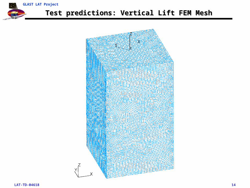
Test predictions: Vertical Lift FEM MeshTest predictions: Vertical Lift FEM Mesh
LAT-TD-04618 15
GLAST LAT Project
Test predictions: Vertical Lift Von Mises StressTest predictions: Vertical Lift Von Mises Stress
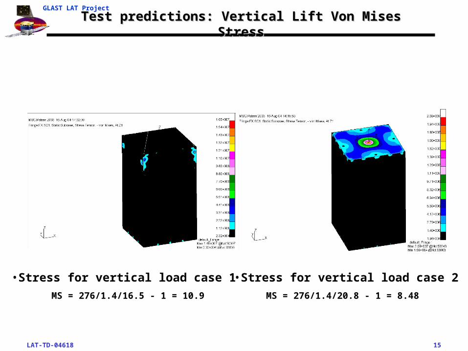
•Stress for vertical load case 2•Stress for vertical load case 1
MS = 276/1.4/16.5 - 1 = 10.9 MS = 276/1.4/20.8 - 1 = 8.48
LAT-TD-04618 16
GLAST LAT Project
Margins of Safety – Vertical Lift LC 1Margins of Safety – Vertical Lift LC 1
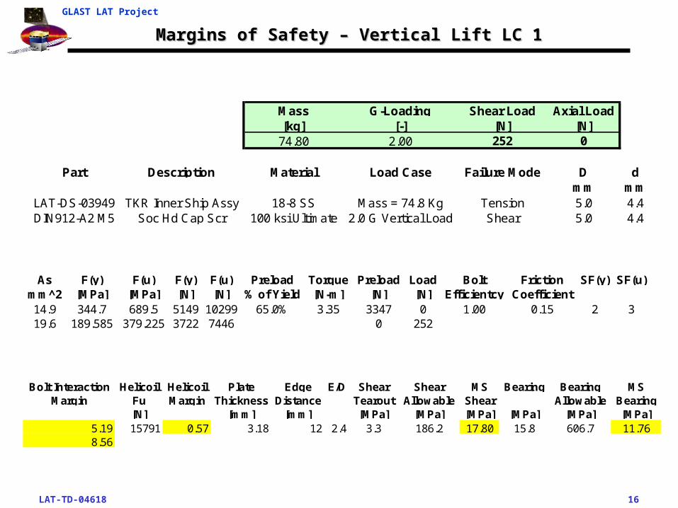
Mass G-Loading Shear Load Axial Load[kg] [-] [N] [N]
74.80 2.00 252 0
Part Description Material Load Case Failure Mode D dmm mm
LAT-DS-03949 TKR Inner Ship Assy 18-8 SS Mass = 74.8 Kg Tension 5.0 4.4DIN912-A2 M5 Soc Hd Cap Scr 100 ksi Ultimate 2.0 G Vertical Load Shear 5.0 4.4
As F(y) F(u) F(y) F(u) Preload Torque Preload Load Bolt Friction SF(y) SF(u)mm^2 [MPa] [MPa] [N] [N] % of Yield [N-m] [N] [N] Efficientcy Coefficient14.9 344.7 689.5 5149 10299 65.0% 3.35 3347 0 1.00 0.15 2 319.6 189.585 379.225 3722 7446 0 252
Bolt Interaction Helicoil Helicoil Plate Edge E/D Shear Shear MS Bearing Bearing MSMargin Fu Margin Thickness Distance Tearout Allowable Shear Allowable Bearing
[N] [mm] [mm] [MPa] [MPa] [MPa] [MPa] [MPa] [MPa]5.19 15791 0.57 3.18 12 2.4 3.3 186.2 17.80 15.8 606.7 11.768.56

LAT-TD-04618 17
GLAST LAT Project
Margins of Safety – Vertical Lift LC 2Margins of Safety – Vertical Lift LC 2
Mass G-Loading Shear Load Axial Load[kg] [-] [N] [N]
74.80 2.00 306 7
Part Description Material Load Case Failure Mode D dmm mm
LAT-DS-03949 TKR Inner Ship Assy 18-8 SS Mass = 74.8 Kg Tension 5.0 4.4DIN912-A2 M5 Soc Hd Cap Scr 100 ksi Ultimate 2.0 G Vertical Load Shear 5.0 4.4
As F(y) F(u) F(y) F(u) Preload Torque Preload Load Bolt Friction SF(y) SF(u)mm^2 [MPa] [MPa] [N] [N] % of Yield [N-m] [N] [N] Efficientcy Coefficient14.9 344.7 689.5 5149 10299 65.0% 3.35 3347 7 1.00 0.15 2 319.6 189.585 379.225 3722 7446 0 306
Bolt Interaction Helicoil Helicoil Plate Edge E/D Shear Shear MS Bearing Bearing MSMargin Fu Margin Thickness Distance Tearout Allowable Shear Allowable Bearing
[N] [mm] [mm] [MPa] [MPa] [MPa] [MPa] [MPa] [MPa]6.79 15791 0.57 3.18 12 2.4 4.0 186.2 14.47 19.3 606.7 9.50
11.14
LAT-TD-04618 18
GLAST LAT Project
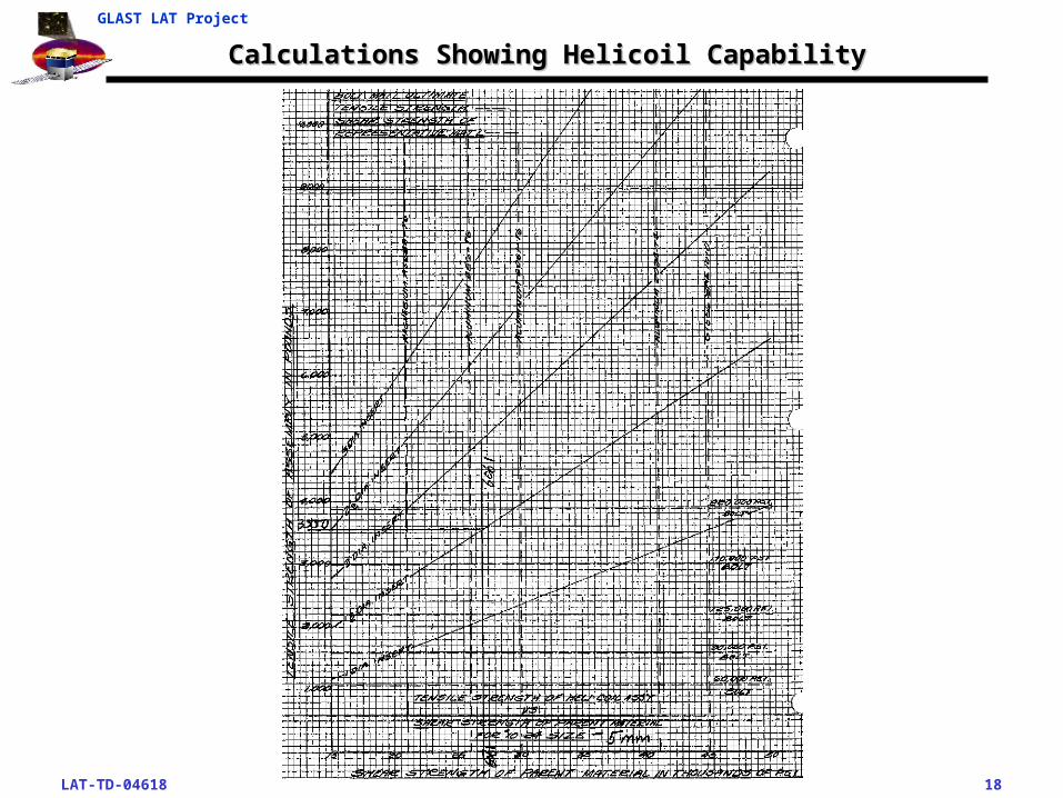
Calculations Showing Helicoil CapabilityCalculations Showing Helicoil Capability
LAT-TD-04618 19
GLAST LAT Project
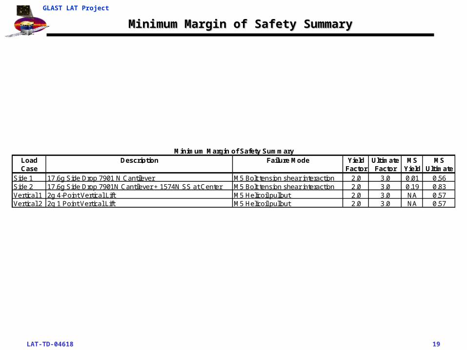
Minimum Margin of Safety SummaryMinimum Margin of Safety Summary
Load Description Failure Mode Yield Ultimate MS MSCase Factor Factor Yield Ultimate
Side 1 17.6g Side Drop 7901 N Cantilever M5 Bolt tension shear interaction 2.0 3.0 0.01 0.56Side 2 17.6g Side Drop 7901N Cantilever + 1574N SS at Center M5 Bolt tension shear interaction 2.0 3.0 0.19 0.83Vertical 1 2g 4-Point Vertical Lift M5 Helicoil pullout 2.0 3.0 NA 0.57Vertical 2 2g 1 Point Vertical Lift M5 Helicoil pullout 2.0 3.0 NA 0.57
Minimum Margin of Safety Summary
LAT-TD-04618 20
GLAST LAT Project
Side Load Test ResultsSide Load Test Results
• Test equipment weighed 130 lbf. So the target loads where reduced to the following:
Load Case 1 = 1646 lbf (7322 N)
Load Case 2 = 2000 lbf (8896 N)
• Actual loads achieved during test where:
Load Case 1 = 1725 lbf (7673 N)
Load Case 2 = 2150 lbf (9564 N)
• The test resulted in no anomalies. Test deemed successful.
LAT-TD-04618 21
GLAST LAT Project
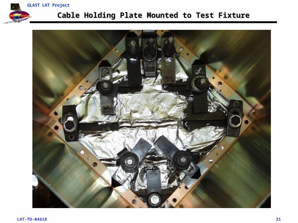
Cable Holding Plate Mounted to Test FixtureCable Holding Plate Mounted to Test Fixture
LAT-TD-04618 22
GLAST LAT Project
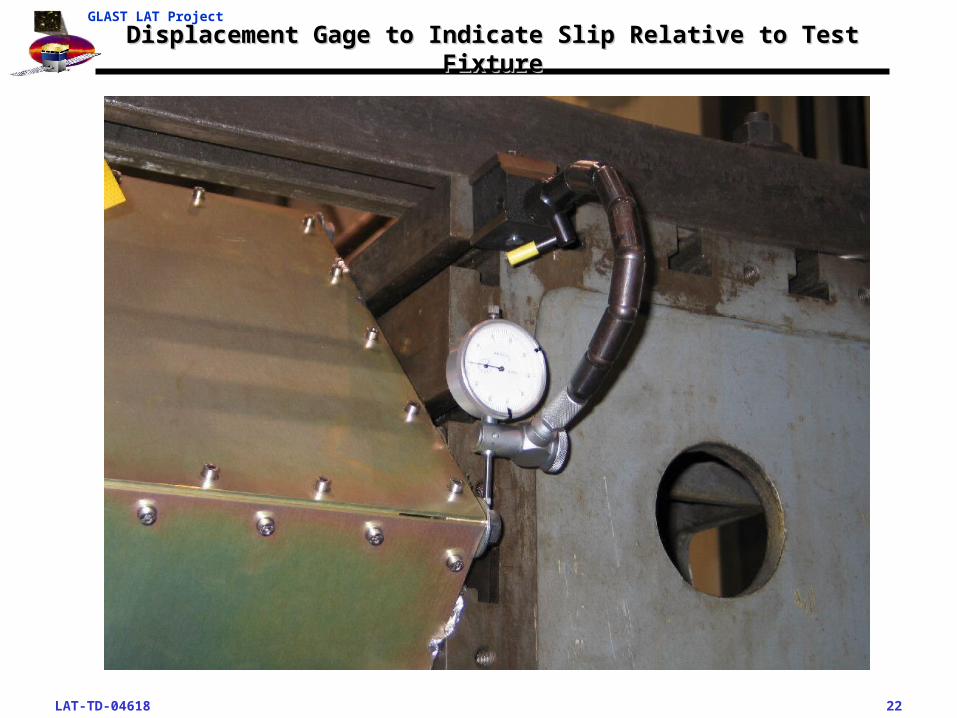
Displacement Gage to Indicate Slip Relative to Test FixtureDisplacement Gage to Indicate Slip Relative to Test Fixture
LAT-TD-04618 23
GLAST LAT Project
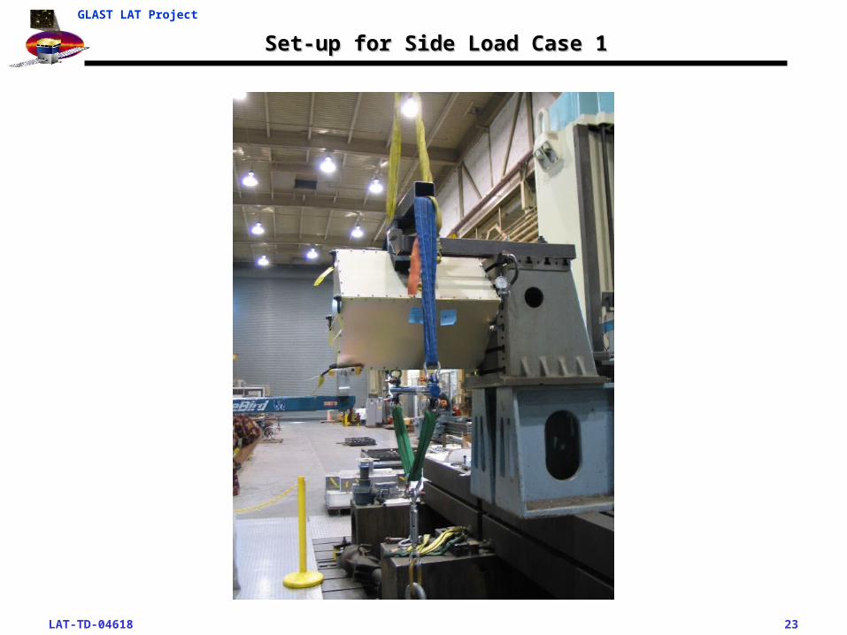
Set-up for Side Load Case 1Set-up for Side Load Case 1
LAT-TD-04618 24
GLAST LAT Project
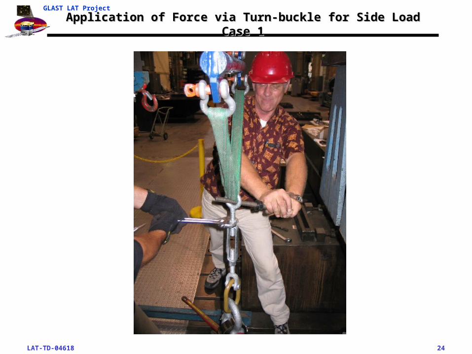
Application of Force via Turn-buckle for Side Load Case 1Application of Force via Turn-buckle for Side Load Case 1
LAT-TD-04618 25
GLAST LAT Project
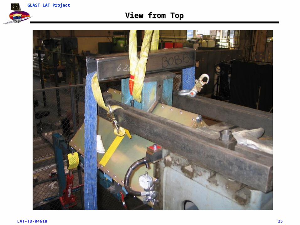
View from TopView from Top
LAT-TD-04618 26
GLAST LAT Project
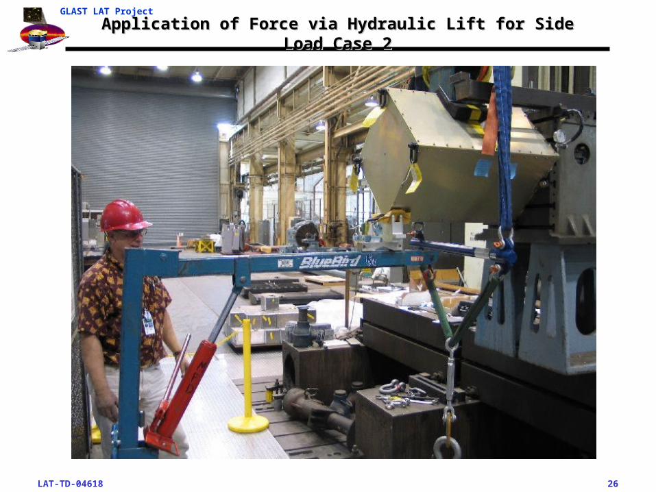
Application of Force via Hydraulic Lift for Side Load Case 2Application of Force via Hydraulic Lift for Side Load Case 2
LAT-TD-04618 27
GLAST LAT Project
Vertical Lift Load Test ResultsVertical Lift Load Test Results
• Actual added mass simulator load was 260 lbf (1157 N) versus required 256 lbf (1139 N).
• The test resulted in no anomalies. Test deemed successful.
LAT-TD-04618 28
GLAST LAT Project
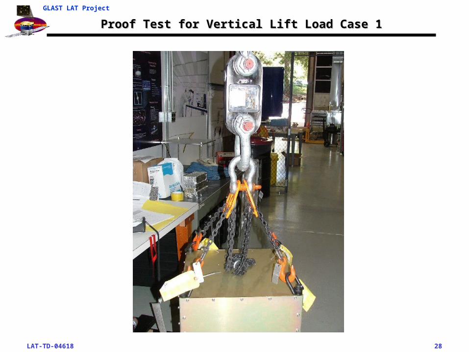
Proof Test for Vertical Lift Load Case 1Proof Test for Vertical Lift Load Case 1
LAT-TD-04618 29
GLAST LAT Project
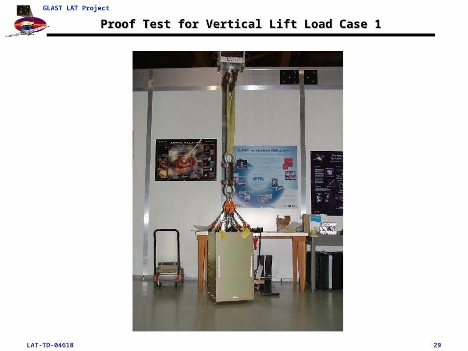
Proof Test for Vertical Lift Load Case 1Proof Test for Vertical Lift Load Case 1
Recommended