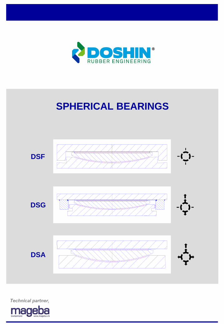
DSA
DSG
DSF
SPHERICAL BEARINGS
2 Introduction
Quality
Main reasons for the quality and durability of the bearings:
• Qualified and experienced specialised staff
• Sophisticated and reliable individual components
• High-quality materials: min. 8mm thick sliding material, long-lasting silicone
grease, etc.
• Quality standard (certified to ISO9001)
Contents Page
Introduction 2
Construction, mode of operation & materials 3
Requirements 4
Identification 5
New sliding material 6
Design and approval 7
DSF series – fixed 8
DSG series - guided sliding 10
DSA series - free sliding 12
Fixing types 14
Special structures 15
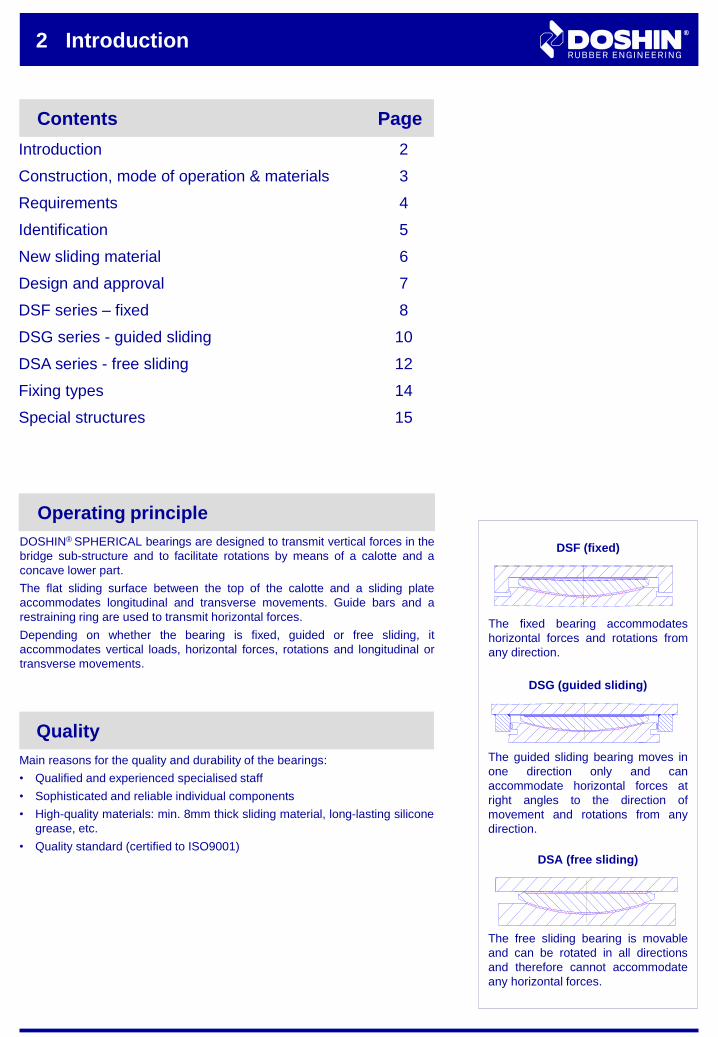
Operating principle
DOSHIN® SPHERICAL bearings are designed to transmit vertical forces in the
bridge sub-structure and to facilitate rotations by means of a calotte and a
concave lower part.
The flat sliding surface between the top of the calotte and a sliding plate
accommodates longitudinal and transverse movements. Guide bars and a
restraining ring are used to transmit horizontal forces.
Depending on whether the bearing is fixed, guided or free sliding, it
accommodates vertical loads, horizontal forces, rotations and longitudinal or
transverse movements.
The fixed bearing accommodates
horizontal forces and rotations from
any direction.
DSF (fixed)
The guided sliding bearing moves in
one direction only and can
accommodate horizontal forces at
right angles to the direction of
movement and rotations from any
direction.
DSG (guided sliding)
The free sliding bearing is movable
and can be rotated in all directions
and therefore cannot accommodate
any horizontal forces.
DSA (free sliding)
TF
Construction, mode of operation & materials 3
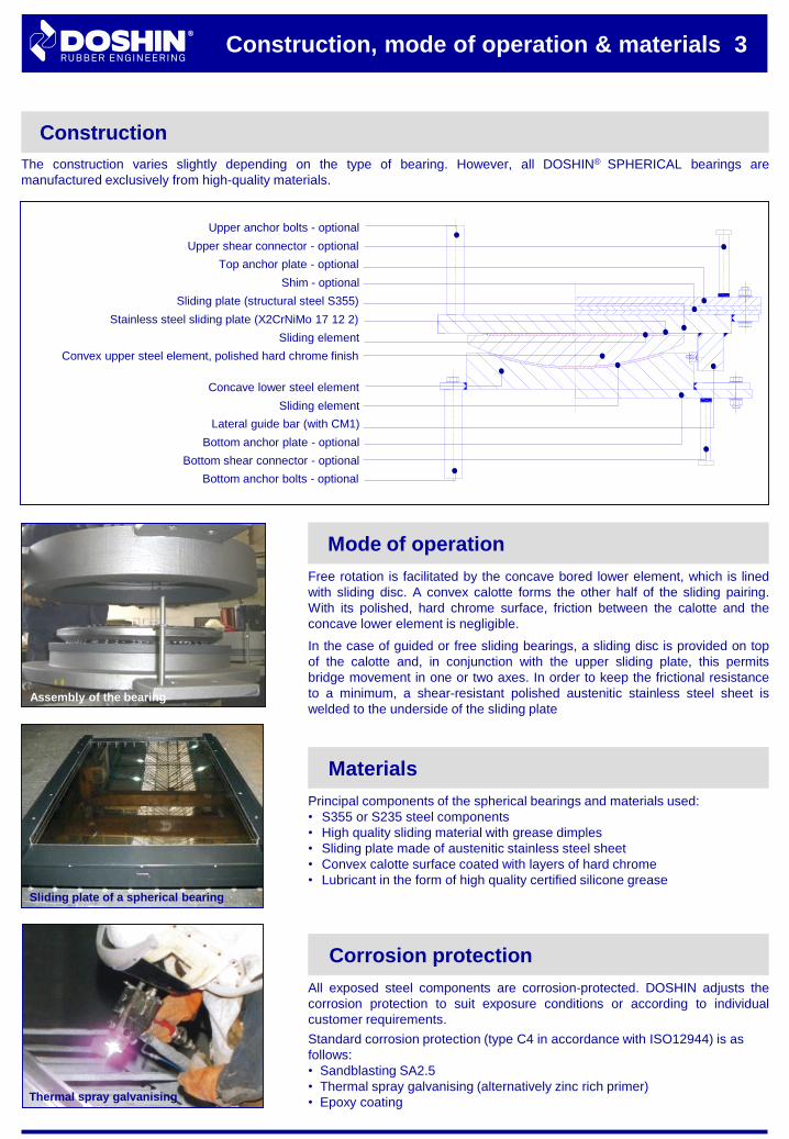
Construction
The construction varies slightly depending on the type of bearing. However, all DOSHIN® SPHERICAL bearings are
manufactured exclusively from high-quality materials.
Upper shear connector - optional
Top anchor plate - optional
Sliding plate (structural steel S355)
Stainless steel sliding plate (X2CrNiMo 17 12 2)
Shim - optional
Sliding element
Concave lower steel element
Convex upper steel element, polished hard chrome finish
Sliding element
Bottom anchor plate - optional
Upper anchor bolts - optional
Bottom shear connector - optional
Bottom anchor bolts - optional
Lateral guide bar (with CM1)
Sliding plate of a spherical bearing
Thermal spray galvanising
Mode of operation
Free rotation is facilitated by the concave bored lower element, which is lined
with sliding disc. A convex calotte forms the other half of the sliding pairing.
With its polished, hard chrome surface, friction between the calotte and the
concave lower element is negligible.
In the case of guided or free sliding bearings, a sliding disc is provided on top
of the calotte and, in conjunction with the upper sliding plate, this permits
bridge movement in one or two axes. In order to keep the frictional resistance
to a minimum, a shear-resistant polished austenitic stainless steel sheet is
welded to the underside of the sliding plate
All exposed steel components are corrosion-protected. DOSHIN adjusts the
corrosion protection to suit exposure conditions or according to individual
customer requirements.
Standard corrosion protection (type C4 in accordance with ISO12944) is as
follows:
• Sandblasting SA2.5
• Thermal spray galvanising (alternatively zinc rich primer)
• Epoxy coating
Corrosion protection
Principal components of the spherical bearings and materials used:
• S355 or S235 steel components
• High quality sliding material with grease dimples
• Sliding plate made of austenitic stainless steel sheet
• Convex calotte surface coated with layers of hard chrome
• Lubricant in the form of high quality certified silicone grease
Materials
Assembly of the bearing
Notes on requirements of EN 1337
DR® SPHERICAL bearings satisfy all requirements of the European bearing
standard EN 1337. This places special demands on the bearing manufacturer,
such as:
(1) Requirement of EN 1337-2: “Provision against contamination of the sliding
surface shall be made by suitable devices. Such protection devices shall be
easily removable for the purpose of inspection."
(2) Requirement of EN 1337-2: "In order to ensure bearing alignment in
accordance with EN 1337-11 a reference surface or other suitable device
shall be installed on the sliding element. The deviation from parallel of the
reference surface with respect to the plane sliding surface shall not exceed
1%."
Movements: The dimension sheets on pages 8 to 13 list the main bearing
dimensions. They apply to the following movements:
DSG longitudinal: 100 mm total transverse: 0 mm
DSA longitudinal: 100 mm total transverse: 40 mm total
Larger longitudinal and transverse movements are possible at
any time. In such cases the dimensions of the sliding plate and
the top anchoring should be adjusted accordingly.
Rotations: The standard rotation about the main axis is 0,010 radians plus
the increased movement in accordance with EN 1337-1. For
larger rotations DOSHIN adapts the bearings individually.
Friction: Slide resistance is calculated on the basis of the Sliding material
stress with relevant superimposed load and horizontal force.
Design criteria
Actions – loads according to EC 1
The load combinations on pages 8 to 13 conform to the “new design concept”
according to Eurocode 1 (EN 1991-2: Actions on structures, Traffic loads on
bridges). If the input loads do not conform to the Eurocode, verification is to be
carried out in accordance with the appropriate standard (DIN, AASHTO, BS,
SIA, etc.).
4 Notes on the requirements in accordance
with EN 1337-7/2
Identification 5
Labelling
The DOSHIN® SPHERICAL bearing is marked with a typographic image on the
upper surface. This facilitates efficient installation of the bearing.
The labelling on the cover or sliding plate gives information about the type, size
and number of a bearing.
In addition on the upper site of the bearing arrows indicate the movement axis
and pre-setting direction as follows:
• Arrows
Arrows indicate the main movement directions of the sliding bearing
• Double arrows
Double arrows on the sliding bearing indicate the pre-setting direction
• Note
Detents used during the construction phase and other special designs are
specially marked. They should be meticulously checked during installation in
accordance with the bearing layout plan.
DOSHIN® SPHERICAL bearings are manufactured in accordance with
European Standard EN 1337-7.
CE conformity
The movement gauge indicates the horizontal movement and the pre-setting value of the bearing:
Movement gauge
0 5 10 15 10 5
Travel W
W2
evx
5 x 10 mmGauge
on the
sliding plate
Pointer on the
lower part
W2
+ evxW2
- evxW2
evx = Pre-setting value at installation
2
W2
+ evx = Slide path to the fixed bearing
- evx = Slide path away from the fixed bearingW
Example:
evx = +75 mm
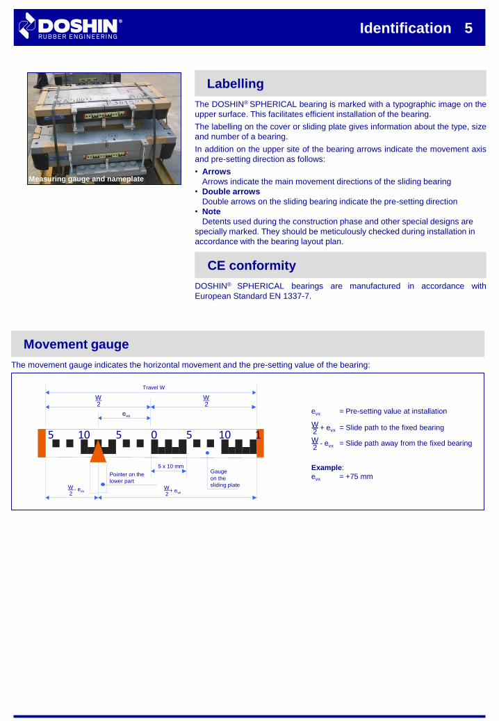
Bearings ready for shipping
Measuring gauge and nameplate
Tests performed
Extensive static load and sliding friction tests have been carried out by
DOSHIN testing laboratory in accordance with the test program for sliding
materials.
More durability of a traditional bearing.
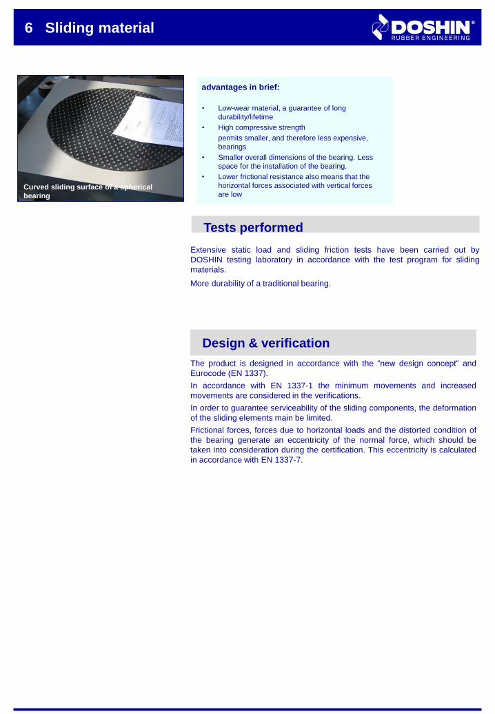
6 Sliding material
Curved sliding surface of a spherical
bearing
advantages in brief:
• Low-wear material, a guarantee of long
durability/lifetime
• High compressive strength
permits smaller, and therefore less expensive,
bearings
• Smaller overall dimensions of the bearing. Less
space for the installation of the bearing.
• Lower frictional resistance also means that the
horizontal forces associated with vertical forces
are low
Design & verification
The product is designed in accordance with the “new design concept“ and
Eurocode (EN 1337).
In accordance with EN 1337-1 the minimum movements and increased
movements are considered in the verifications.
In order to guarantee serviceability of the sliding components, the deformation
of the sliding elements main be limited.
Frictional forces, forces due to horizontal loads and the distorted condition of
the bearing generate an eccentricity of the normal force, which should be
taken into consideration during the certification. This eccentricity is calculated
in accordance with EN 1337-7.
Design 7
Areas of application
DOSHIN® SPHERICAL bearings are particularly suitable for the following
areas of application:
•Structures with frequent high deformations from traffic
•Structures requiring fast bearing movement, such as bridges for high-speed
railways
•Medium to high loads
•Structures with high accumulated bearing slide paths
The following load tables and dimensions (see pages 8 to 13) have
reproduced the maximum chargeable loads of several types of spherical
bearings.
Following design parameter are taken in consideration: the required minimum
movements and movement increases in accordance with EN 1337-1, an area
of application at low temperatures (> -35°C) and a sliding plate minimum
thickness of 4% of the sliding plate diagonals.
Load tables and dimensions
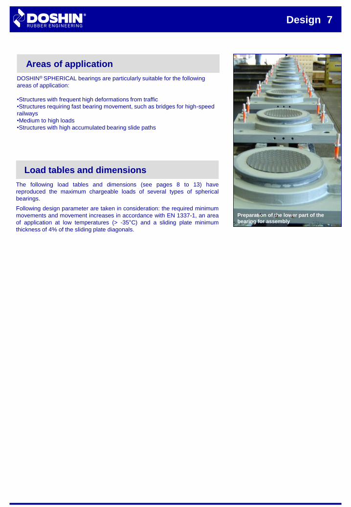
Preparation of the lower part of the
bearing for assembly
Function
DOSHIN® SPHERICAL DSF bearings are fixed in position. They can
accommodate horizontal forces and rotations from any direction.
Theoretically, movement is zero with fixed bearings. However, in practice there
is a total clearance of up to 1 mm between top and lower bearing parts.
8 DSF series – Fixed
Load combination
All standard bearings are designed to be able to withstand maximum
concurrent vertical and horizontal forces.
The maximum permissible horizontal forces are based on a concurrent
minimum vertical load of about 30% of the maximum superimposed load. The
horizontal forces Vxy are assumed at 10% of the vertical load. From these
assumptions differing requirements on the bearing are possible at any time and
appropriate bearings can be provided on request.
Concrete stress
The concrete stress is calculated in accordance with the European Standard
EC 2 (partial area stress).
In order to be able to fully utilise the high stability of the sliding material, we
recommend using high-strength concrete (C50/60).
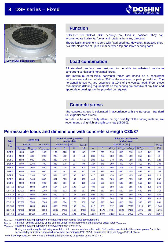
Permissible loads and dimensions with concrete strength C30/37
NRd,max :
NRd,min :
VxyRd,max :
maximum bearing capacity of the bearing under normal force (compression)
minimum bearing capacity of the bearing under normal force with simultaneous shear force VxyRd, max
maximum bearing capacity of the bearing under shear force
Lower DSF bearing part
During dimensioning the following were taken into account and complied with: Deformation constraint of the carrier plates Δw in the
serviceability limit state, increased movement according to EN 1337-1, permissible stresses fd,RSL=180/1.4 N/mm²
Type
&
Size
Loads [kN]Spherical bearing without
anchor plate
Spherical bearing with
anchor plate
Vertical Horizontal Dimensions [mm] Weight
[kg]
Dimensions [mm] Weight
[kg]N Rd, max N Rd, min V xyRd, max A B H A B APU_x APU_y APO_x APO_y H
DSF 1 1'000 300 100 182 228 76 32 177 223 316 316 316 316 141 69
DSF 2 2'000 600 200 236 292 80 48 236 292 330 330 350 350 137 90
DSF 3 3'000 900 300 289 340 89 66 289 338 370 370 380 380 147 120
DSF 4 4'000 1'200 400 332 375 90 80 327 375 390 390 410 410 143 139
DSF 5 5'000 1'500 500 364 415 98 100 363 401 405 405 425 425 151 161
DSF 6 6'000 1'800 600 396 441 102 117 385 432 446 430 455 455 151 185
DSF 7 7'000 2'100 700 434 487 105 145 417 472 476 460 495 495 148 215
DSF 8 8'000 2'400 800 461 523 104 163 446 514 509 485 535 535 138 232
DSF 9 9'000 2'700 900 496 581 99 186 456 530 519 500 550 550 137 245
DSF 10 10'000 3'000 1'000 514 570 108 200 489 561 580 526 585 585 138 278
DSF 12 12'000 3'600 1'200 556 602 125 257 509 580 586 562 600 600 146 314
DSF 15 15'000 4'500 1'500 620 671 147 375 595 667 684 637 690 690 160 454
DSF 20 20'000 6'000 2'000 715 761 165 538 655 769 748 732 790 790 168 624
DSF 25 25'000 7'500 2'500 802 884 172 750 787 876 848 810 900 900 189 881
DSF 30 30'000 9'000 3'000 880 1'027 167 944 812 988 912 897 1'010 1'010 191 1'140
DSF 40 40'000 12'000 4'000 1'031 1'237 168 1'389 951 1'173 1'054 1'029 1'195 1'195 215 1'776
DSF 50 50'000 15'000 5'000 1'155 1'403 181 1'920 1'133 1'374 1'193 1'155 1'402 1'401 241 2'657
Note: Due to production tolerances the bearing height H may be greater by up to 10 mm.
x
y
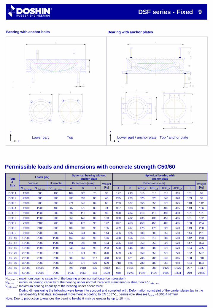
DSF series - Fixed 9
Note: Due to production tolerances the bearing height H may be greater by up to 10 mm.
Bearing with anchor bolts Bearing with anchor plates
Permissible loads and dimensions with concrete strength C50/60
Lower part Top Lower part / anchor plate Top / anchor plate
x
y
Type
&
Size
Loads [kN]Spherical bearing without
anchor plate
Spherical bearing with
anchor plate
Vertical Horizontal Dimensions [mm] Weight
[kg]
Dimensions [mm] Weight
[kg]N Rd, max N Rd, min V xyRd, max A B H A B APU_x APU_y APO_x APO_y H
DSF 1 1'000 300 100 182 228 76 32 177 219 316 316 316 316 131 66
DSF 2 2'000 600 200 236 292 80 48 225 279 325 325 340 340 139 86
DSF 3 3'000 900 300 274 340 89 65 263 327 355 355 375 375 148 112
DSF 4 4'000 1'200 400 307 375 85 74 307 373 390 390 405 405 143 136
DSF 5 5'000 1'500 500 339 413 89 90 328 404 410 410 430 430 151 161
DSF 6 6'000 1'800 600 366 446 89 103 350 432 435 435 455 455 151 182
DSF 7 7'000 2'100 700 382 472 96 122 377 463 450 450 485 485 150 204
DSF 8 8'000 2'400 800 409 503 95 135 409 497 475 475 520 520 149 230
DSF 9 9'000 2'700 900 447 541 89 144 436 526 500 500 550 550 144 251
DSF 10 10'000 3'000 1'000 469 563 95 166 458 556 515 515 580 580 142 273
DSF 12 12'000 3'600 1'200 491 593 94 184 496 600 550 550 620 620 147 324
DSF 15 15'000 4'500 1'500 545 667 96 233 528 646 580 580 670 670 164 405
DSF 20 20'000 6'000 2'000 615 771 99 320 599 747 650 650 770 770 162 527
DSF 25 25'000 7'500 2'500 680 868 117 468 653 821 705 705 845 845 188 710
DSF 30 30'000 9'000 3'000 756 972 120 599 718 926 780 780 950 950 184 894
DSF 40 40'000 12'000 4'000 896 1'184 136 1'012 821 1'101 905 905 1'125 1'125 207 1'417
DSF 50 50'000 15'000 5'000 1'032 1'366 153 1'500 940 1'274 1'025 1'025 1'305 1'304 219 2'036
NRd,max :
NRd,min :
VxyRd,max :
maximum bearing capacity of the bearing under normal force (compression)
minimum bearing capacity of the bearing under normal force with simultaneous shear force VxyRd, max
maximum bearing capacity of the bearing under shear force
During dimensioning the following were taken into account and complied with: Deformation constraint of the carrier plates Δw in the
serviceability limit state, increased movement according to EN 1337-1, permissible stresses fd,RSL=180/1.4 N/mm²
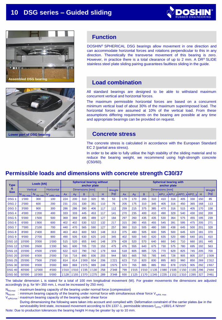
10 DSG series – Guided sliding
Function
DOSHIN® SPHERICAL DSG bearings allow movement in one direction and
can accommodate horizontal forces and rotations perpendicular to this in any
direction. Theoretically the transverse movement of this bearing is zero.
However, in practice there is a total clearance of up to 2 mm. A DR® SLIDE
stainless steel plate sliding pairing guarantees faultless sliding in the guide.
All standard bearings are designed to be able to withstand maximum
concurrent vertical and horizontal forces.
The maximum permissible horizontal forces are based on a concurrent
minimum vertical load of about 30% of the maximum superimposed load. The
horizontal forces are assumed at 10% of the vertical load. From these
assumptions differing requirements on the bearing are possible at any time
and appropriate bearings can be provided on request.
Load combination
The concrete stress is calculated in accordance with the European Standard
EC 2 (partial area stress).
In order to be able to fully utilise the high stability of the sliding material and to
reduce the bearing weight, we recommend using high-strength concrete
(C50/60).
Concrete stress
Permissible loads and dimensions with concrete strength C30/37
Assembled DSG bearing
Type
&
Size
Loads [kN]Spherical bearing without
anchor plate
Spherical bearing with
anchor plate
Vertical Horizontal Dimensions [mm] Weight
[kg]
Dimensions [mm] Weight
[kg]N Rd, max N Rd, min V xyRd, max Ax Ay B L H Ax Ay B L APU_x APU_y APO_x APO_y H
DSG 1 1'000 300 100 224 200 310 320 95 53 178 170 265 310 410 316 405 330 150 85
DSG 2 2'000 600 200 231 231 330 351 110 76 205 175 310 345 405 316 450 365 168 113
DSG 3 3'000 900 300 286 286 390 406 117 112 259 215 375 385 470 316 515 405 170 158
DSG 4 4'000 1'200 400 333 333 445 453 117 141 270 235 400 410 490 329 540 430 192 200
DSG 5 5'000 1'500 500 369 369 495 489 127 184 297 260 435 435 530 364 575 455 195 239
DSG 6 6'000 1'800 600 402 402 530 522 132 217 315 280 455 455 545 391 595 475 205 271
DSG 7 7'000 2'100 700 440 470 565 590 127 257 360 310 505 480 590 438 645 500 201 328
DSG 8 8'000 2'400 800 463 463 600 583 148 313 375 480 505 600 595 500 645 620 181 370
DSG 9 9'000 2'700 900 490 505 630 625 143 345 402 500 540 620 635 520 680 640 181 410
DSG 10 10'000 3'000 1'000 515 520 655 640 148 379 428 520 570 640 660 540 710 660 181 445
DSG 12 12'000 3'600 1'200 561 600 705 720 153 475 476 555 640 675 730 575 780 695 192 563
DSG 15 15'000 4'500 1'500 622 622 790 742 179 644 518 605 685 725 770 629 825 745 205 700
DSG 20 20'000 6'000 2'000 716 716 890 836 203 944 583 665 765 785 845 728 905 805 237 1'009
DSG 25 25'000 7'500 2'500 814 814 1'000 934 206 1'221 623 710 820 830 895 803 960 850 269 1'312
DSG 30 30'000 9'000 3'000 869 869 1'075 989 248 1'675 670 765 885 885 950 878 1'025 905 292 1'657
DSG 40 40'000 12'000 4'000 1'010 1'010 1'235 1'130 258 2'348 799 1'015 1'010 1'135 1'080 1'035 1'150 1'155 296 2'444
DSG 50 50'000 15'000 5'000 1'128 1'155 1'370 1'275 289 3'348 930 1'125 1'170 1'245 1'235 1'152 1'310 1'265 327 3'461
Note: Due to production tolerances the bearing height H may be greater by up to 10 mm.
NRd,max :
NRd,min :
VxyRd,max :
maximum bearing capacity of the bearing under normal force (compression)
minimum bearing capacity of the bearing under normal force with simultaneous shear force VxyRd, max
maximum bearing capacity of the bearing under shear force
During dimensioning the following were taken into account and complied with: Deformation constraint of the carrier plates Δw in the
serviceability limit state, increased movement according to EN 1337-1, permissible stresses fd,RSL=180/1.4 N/mm²
The tabular dimension L is stated for a total of 100 mm longitudinal movement (W). For greater movements the dimensions are adjusted
accordingly (e.g. for W= 350 mm, L must be increased by 250 mm).
Lower part of DSG bearing
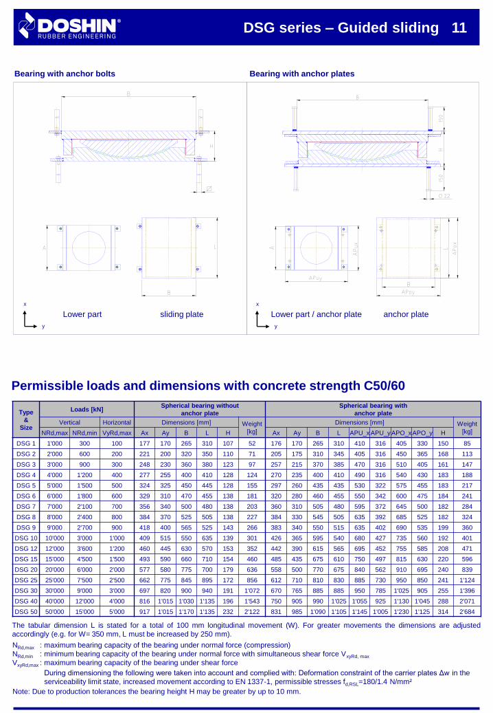
Lower part / anchor plateLower part sliding plate
Bearing with anchor bolts Bearing with anchor plates
Permissible loads and dimensions with concrete strength C50/60
anchor plate
x
y
x
y
DSG series – Guided sliding 11
Type
&
Size
Loads [kN]Spherical bearing without
anchor plate
Spherical bearing with
anchor plate
Vertical Horizontal Dimensions [mm] Weight
[kg]
Dimensions [mm] Weight
[kg]NRd,max NRd,min VyRd,max Ax Ay B L H Ax Ay B L APU_x APU_y APO_xAPO_y H
DSG 1 1'000 300 100 177 170 265 310 107 52 176 170 265 310 410 316 405 330 150 85
DSG 2 2'000 600 200 221 200 320 350 110 71 205 175 310 345 405 316 450 365 168 113
DSG 3 3'000 900 300 248 230 360 380 123 97 257 215 370 385 470 316 510 405 161 147
DSG 4 4'000 1'200 400 277 255 400 410 128 124 270 235 400 410 490 316 540 430 183 188
DSG 5 5'000 1'500 500 324 325 450 445 128 155 297 260 435 435 530 322 575 455 183 217
DSG 6 6'000 1'800 600 329 310 470 455 138 181 320 280 460 455 550 342 600 475 184 241
DSG 7 7'000 2'100 700 356 340 500 480 138 203 360 310 505 480 595 372 645 500 182 284
DSG 8 8'000 2'400 800 384 370 525 505 138 227 384 330 545 505 635 392 685 525 182 324
DSG 9 9'000 2'700 900 418 400 565 525 143 266 383 340 550 515 635 402 690 535 199 360
DSG 10 10'000 3'000 1'000 409 515 550 635 139 301 426 365 595 540 680 427 735 560 192 401
DSG 12 12'000 3'600 1'200 460 445 630 570 153 352 442 390 615 565 695 452 755 585 208 471
DSG 15 15'000 4'500 1'500 493 590 660 710 154 460 485 435 675 610 750 497 815 630 220 596
DSG 20 20'000 6'000 2'000 577 580 775 700 179 636 558 500 770 675 840 562 910 695 240 839
DSG 25 25'000 7'500 2'500 662 775 845 895 172 856 612 710 810 830 885 730 950 850 241 1'124
DSG 30 30'000 9'000 3'000 697 820 900 940 191 1'072 670 765 885 885 950 785 1'025 905 255 1'396
DSG 40 40'000 12'000 4'000 816 1'015 1'030 1'135 196 1'543 750 905 990 1'025 1'055 925 1'130 1'045 288 2'071
DSG 50 50'000 15'000 5'000 917 1'015 1'170 1'135 232 2'122 831 985 1'090 1'105 1'145 1'005 1'230 1'125 314 2'684
Note: Due to production tolerances the bearing height H may be greater by up to 10 mm.
NRd,max :
NRd,min :
VxyRd,max :
maximum bearing capacity of the bearing under normal force (compression)
minimum bearing capacity of the bearing under normal force with simultaneous shear force VxyRd, max
maximum bearing capacity of the bearing under shear force
During dimensioning the following were taken into account and complied with: Deformation constraint of the carrier plates Δw in the
serviceability limit state, increased movement according to EN 1337-1, permissible stresses fd,RSL=180/1.4 N/mm²
The tabular dimension L is stated for a total of 100 mm longitudinal movement (W). For greater movements the dimensions are adjusted
accordingly (e.g. for W= 350 mm, L must be increased by 250 mm).
Type
&
Size
Loads [kN]Spherical bearing without
anchor plate
Spherical bearing with
anchor plate
Vertical Dimensions [mm] Weight
[kg]
Dimensions [mm] Weight
[kg]NRd,max NRd,min A B L H A B L APU_x APU_y APO_x APO_y H
DSA 1 1'000 300 183 243 303 67 30 126 215 290 316 316 345 316 102 46
DSA 2 2'000 600 236 296 356 70 43 171 260 320 316 316 390 340 114 63
DSA 3 3'000 900 278 338 398 77 60 205 295 355 340 316 425 375 124 84
DSA 4 4'000 1'200 320 380 440 81 76 235 325 385 365 321 455 405 124 98
DSA 5 5'000 1'500 364 424 484 83 95 257 350 410 390 354 480 430 135 120
DSA 6 6'000 1'800 397 457 517 86 115 285 375 435 420 389 505 455 137 141
DSA 7 7'000 2'100 417 477 537 104 152 301 395 455 435 422 525 475 148 168
DSA 8 8'000 2'400 456 516 576 93 158 331 425 485 465 452 555 505 146 191
DSA 9 9'000 2'700 479 539 599 104 193 339 430 490 478 478 560 510 158 224
DSA 10 10'000 3'000 507 567 627 103 214 368 460 520 506 506 590 540 158 254
DSA 12 12'000 3'600 548 608 668 120 284 386 480 540 560 560 610 560 186 341
DSA 15 15'000 4'500 616 676 736 129 390 452 545 605 625 625 675 625 191 447
DSA 20 20'000 6'000 708 768 828 138 539 536 630 690 709 709 760 710 206 638
DSA 25 25'000 7'500 797 857 917 142 688 574 665 725 799 799 800 798 236 919
DSA 30 30'000 9'000 881 941 1'001 141 835 637 740 800 862 862 870 856 268 1'189
DSA 40 40'000 12'000 1'022 1'082 1'142 157 1'246 837 945 1'005 1'028 1'028 1'080 1'030 237 1'619
DSA 50 50'000 15'000 1'147 1'207 1'267 178 1'785 914 1'017 1'077 1'139 1'139 1'150 1'133 283 2'310
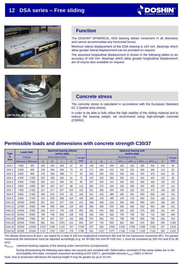
The concrete stress is calculated in accordance with the European Standard
EC 2 (partial area stress).
In order to be able to fully utilise the high stability of the sliding material and to
reduce the bearing weight, we recommend using high-strength concrete
(C50/60).
Concrete stress
12 DSA series – Free sliding
Function
The DOSHIN® SPHERICAL DSA bearing allows movement in all directions
and cannot accommodate any horizontal forces.
Minimum lateral displacement of the DSA bearing is ±20 mm. Bearings which
allow greater lateral displacement can be provided on request.
The assumed longitudinal displacement is shown in the following tables to an
accuracy of ±50 mm. Bearings which allow greater longitudinal displacement
are of course also available on request.
Permissible loads and dimensions with concrete strength C30/37
NRd,max : maximum bearing capacity of the bearing under normal force (compression)
During dimensioning the following were taken into account and complied with: Deformation constraint of the carrier plates Δw in the
serviceability limit state, increased movement according to EN 1337-1, permissible stresses fd,RSL=180/1.4 N/mm²
Assembled DSA bearing
DR®SLIDE disc on the calotte
Note: Due to production tolerances the bearing height H may be greater by up to 10 mm.
The tabular dimensions B and L are stated for a total of 100 mm longitudinal movement (W) and 40 mm transverse movement (W‘). For greater
movements the dimensions must be adjusted accordingly (e.g. for W=350 mm and W‘=100 mm, L must be increased by 250 mm and B by 60
mm).
Lower part
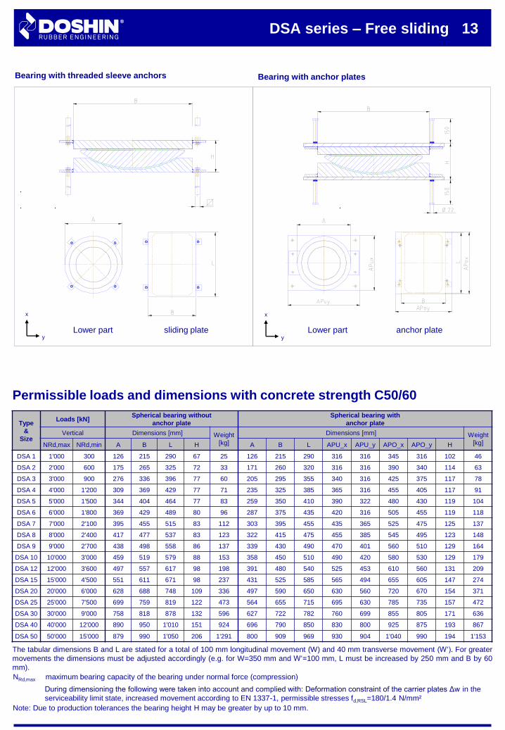
DSA series – Free sliding 13
Bearing with threaded sleeve anchors Bearing with anchor plates
Permissible loads and dimensions with concrete strength C50/60
anchor plateLower part sliding plate
x
y
x
y
Type
&
Size
Loads [kN]Spherical bearing without
anchor plate
Spherical bearing with
anchor plate
Vertical Dimensions [mm] Weight
[kg]
Dimensions [mm] Weight
[kg]NRd,max NRd,min A B L H A B L APU_x APU_y APO_x APO_y H
DSA 1 1'000 300 126 215 290 67 25 126 215 290 316 316 345 316 102 46
DSA 2 2'000 600 175 265 325 72 33 171 260 320 316 316 390 340 114 63
DSA 3 3'000 900 276 336 396 77 60 205 295 355 340 316 425 375 117 78
DSA 4 4'000 1'200 309 369 429 77 71 235 325 385 365 316 455 405 117 91
DSA 5 5'000 1'500 344 404 464 77 83 259 350 410 390 322 480 430 119 104
DSA 6 6'000 1'800 369 429 489 80 96 287 375 435 420 316 505 455 119 118
DSA 7 7'000 2'100 395 455 515 83 112 303 395 455 435 365 525 475 125 137
DSA 8 8'000 2'400 417 477 537 83 123 322 415 475 455 385 545 495 123 148
DSA 9 9'000 2'700 438 498 558 86 137 339 430 490 470 401 560 510 129 164
DSA 10 10'000 3'000 459 519 579 88 153 358 450 510 490 420 580 530 129 179
DSA 12 12'000 3'600 497 557 617 98 198 391 480 540 525 453 610 560 131 209
DSA 15 15'000 4'500 551 611 671 98 237 431 525 585 565 494 655 605 147 274
DSA 20 20'000 6'000 628 688 748 109 336 497 590 650 630 560 720 670 154 371
DSA 25 25'000 7'500 699 759 819 122 473 564 655 715 695 630 785 735 157 472
DSA 30 30'000 9'000 758 818 878 132 596 627 722 782 760 699 855 805 171 636
DSA 40 40'000 12'000 890 950 1'010 151 924 696 790 850 830 800 925 875 193 867
DSA 50 50'000 15'000 879 990 1'050 206 1'291 800 909 969 930 904 1'040 990 194 1'153
NRd,max : maximum bearing capacity of the bearing under normal force (compression)
During dimensioning the following were taken into account and complied with: Deformation constraint of the carrier plates Δw in the
serviceability limit state, increased movement according to EN 1337-1, permissible stresses fd,RSL=180/1.4 N/mm²
Note: Due to production tolerances the bearing height H may be greater by up to 10 mm.
The tabular dimensions B and L are stated for a total of 100 mm longitudinal movement (W) and 40 mm transverse movement (W‘). For greater
movements the dimensions must be adjusted accordingly (e.g. for W=350 mm and W‘=100 mm, L must be increased by 250 mm and B by 60
mm).
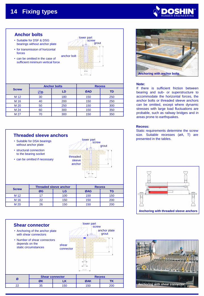
14 Fixing types
Anchor bolts
Note:
If there is sufficient friction between
bearing and sub- or superstructure to
accommodate the horizontal forces, the
anchor bolts or threaded sleeve anchors
can be omitted, except where dynamic
stresses with large load fluctuations are
probable, such as railway bridges and in
areas prone to earthquakes.
Recess:
Static requirements determine the screw
size. Suitable recesses (øA, T) are
presented in the tables.Threaded sleeve anchors
Shear connector• Anchoring of the anchor plate
with shear connectors
• Number of shear connectors
depends on the
static circumstances
• Suitable for DSA bearings
without anchor plate
• structural connection
to the bearing socket
• can be omitted if necessary
• Suitable for DSF & DSG
bearings without anchor plate
• for transmission of horizontal
forces
• can be omitted in the case of
sufficient minimum vertical force
ScrewAnchor bolts Recess
□D LD ØAD TD
M 12 30 180 150 250
M 16 40 200 150 250
M 20 50 250 150 300
M 24 60 300 150 350
M 27 70 300 150 350
Anchoring with anchor bolts
∕
Anchoring with shear connector
groutscrew
anchor bolt
groutscrew
threaded
sleeve
anchor
shear
connector
anchor plate
screw
grout
lower part
lower part
lower part
ScrewThreaded sleeve anchor Recess
ØG LG ØAG TG
M 12 17 100 150 150
M 16 22 150 150 200
M 20 26 150 150 200
ØShear connector Recess
ØK LK ØAK TK
22 35 150 150 200
Anchoring with threaded sleeve anchors
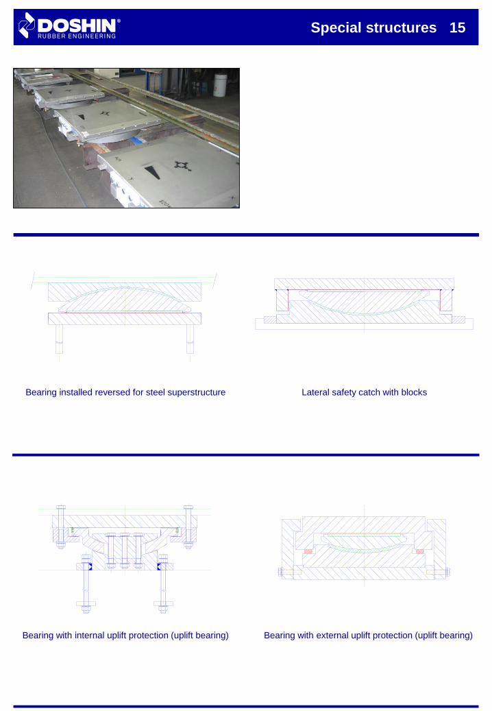
Special structures 15
Lateral safety catch with blocksBearing installed reversed for steel superstructure
Bearing with external uplift protection (uplift bearing)Bearing with internal uplift protection (uplift bearing)
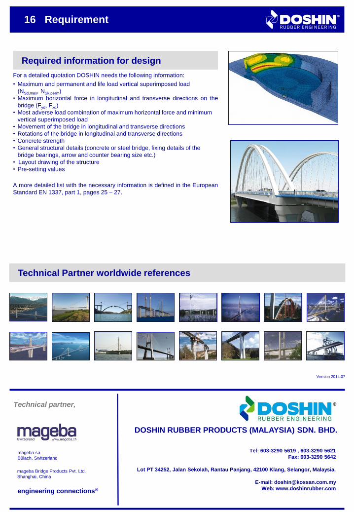
16 Requirement
Required information for design
For a detailed quotation DOSHIN needs the following information:
• Maximum and permanent and life load vertical superimposed load
(NSd,max, NSk,perm)
• Maximum horizontal force in longitudinal and transverse directions on the
bridge (Fyd, Fxd)
• Most adverse load combination of maximum horizontal force and minimum
vertical superimposed load
• Movement of the bridge in longitudinal and transverse directions
• Rotations of the bridge in longitudinal and transverse directions
• Concrete strength
• General structural details (concrete or steel bridge, fixing details of the
bridge bearings, arrow and counter bearing size etc.)
• Layout drawing of the structure
• Pre-setting values
A more detailed list with the necessary information is defined in the European
Standard EN 1337, part 1, pages 25 – 27.
Technical Partner worldwide references
Version 2014.07
engineering connections®
Employees of the technical department
mageba sa
Bülach, Switzerland
mageba Bridge Products Pvt. Ltd.
Shanghai, China
DOSHIN RUBBER PRODUCTS (MALAYSIA) SDN. BHD.
Tel: 603-3290 5619 , 603-3290 5621
Fax: 603-3290 5642
Lot PT 34252, Jalan Sekolah, Rantau Panjang, 42100 Klang, Selangor, Malaysia.
E-mail: [email protected]
Web: www.doshinrubber.com
Technical partner,
Recommended