Kumbhojkar’s
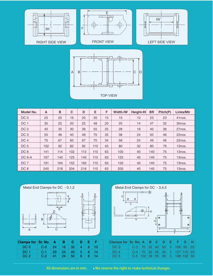
CABLE DRAG CHAIN
DC - 0 DC - 1 DC - 2
DC - 3 DC - 4 DC - 5
DC - 6 DC - 7 DC - 8

4. Length of Drag Chain in Bend (BL)
BL = BR x + 2 P guide channels. These channels fitted on the side of Drag Chain facilitate movement during
5. Height of Moving End (MH) return stroke of chain when it comes to its MH = 2BR + F original position and does not deviate side ways
from the fixed points thus avoiding tension & 6 The movement of Drag Chain should be on breakage.
smooth surface otherwise we suggest use of
D
C
E
B
AH
GF
Metal End Clamps for DC - 6,7,8
Fixed End Side Metal Clamps
Clamps for Sr. No. A B C D E F G H
DC 6 FC-6 90 45 55 50 4 213 163 23
DC 7 FC-7 90 45 55 50 4 262 212 23DC 8 FC-8 90 45 55 50 4 313 263 23
A
B D
C
27
8
E
F
G
Moving End Side Metal Clamps
Clamps for Sr. No. A B C D E F G
DC 6 MC-6 46 46 30 15 15 218 172
DC 7 MC-7 46 46 30 15 15 268 222DC 8 MC-8 46 46 30 15 15 322 276
DL
MOVING END
FIXED ENDBR
BL Schematic Diagram ShowingInstallation In Case of Long Travel
TL2
DL
UL
PMOVING END
BR
FIXED END
BL
Schematic diagram Showing unsupported Arrangement
MH
Guidelines for Installation of Cable Drag Chain
Classification : TL DL
UL BL
BR P
MH F
Total length of Travel Length of Drag Chain
Unsupported Length Length of Drag Chain in Bend
Bending Radius Pitch
Height of Moving End External height of Drag Chain
1. The fixed end of the cable carrier should be in the centre of the total travel length (TL). This arrangement results in minimum length of Drag Chain.
2. Unsupported Length (UL)
3. Length Of Drag Chain( DL )In long travel the upper links may glide on the lower links without hampering the motion. The portion glides easily on top of one another as all is made in plastic. However to avoid this we suggest you to use supports/guide channels below the sagging parts.
2+ BLDL
TL=
2UL = TL
Ps. : Kindly note above mentioned are guidelines for your reference while installation of drag chain, However we recommend you to take expert opinion from your installation engineers.

KUMBHOJKAR PLASTIC MOULDERS129, Narayan peth, Sitaphal Baug Colony, Near Mati Ganpati, Pune : 411 030. Tel.: 020-24450055/24450060.
Fax : 020-24480544, Website : http://www.plamoulds.com. Email : [email protected]
side by side in case number of cables is more, Kumbhojkar ’s Cable Drag Chain increases cable/hoses life, modular design designed, developed & manufactured in simplifies cable/hose maintenance.Pune from 1986. This system is a reliable
solution to carry cables & hoses in motion The Cable Drag Chain is assemblies of single
on almost all type of sophisticated units that are snap fitted to form chain to
machines like NC, CNC to rugged specific length.
cranes.
Advantage - The hoses & electrical cables connected to machinery parts in motion may get damaged as direct tension is applied on them; instead the use of Drag Chain eliminates this problem as the tension is applied on Drag Chain thus keeping the Cables & hoses intact & facilitating smooth movement.
Salient features include less weight, low noise, non-conductive, easy handling, non corrosive, easy of assembly due to snap fitting, maintenance free, available in custom lengths, separators to segregate cables/hoses, can be used for
Ways
OpposingCombinedHorizontal/Vertical
VerticalOption 2
VerticalOption 1
Horizontal
900
N I troducti ew n on
N I troducti ew n on
Model DC-6, DC-7, DC-8
Exclusive Slide Fit Design
Design
Under
Registration
TM

KUMBHOJKAR PLASTIC MOULDERS129, NARAYAN PETH, SITAPHALBAUG COLONY, NEAR MATI GANPATI, PUNE : 411 030. INDIA. TEL. : 020-24450055/60, FAX : 020-24480544 E-Mail : [email protected] WEB SITE : http://www.plamoulds.com
GUIDELINES FOR USE OF GUIDE CHANNEL A Guide channel / Support Tray is always necessary for smooth functioning of the Drag Chain. Especially in case of Long Travel Guide Channels are a must.
We suggest that inner width of guide channel should be approximately 5mm more than drag chain width & 2mm on either side tapered on the outer side.
The height of guide channel must be minimum half of the total height of the drag chain link. In case of Long Travel the Guide Channel has to be fitted with Support Rollers so as to guide the drag chain and thus prevent it from falling or in case where the top portion cannot glide on the lower portion of drag chain. The Spacing & Number of such Support Rollers will vary as length increases.
The guide channels need to fixed & aligned in Straight line with no protruding parts on the inner side like bolt heads/ nuts etc. as these may entangle with Drag Chain restricting its motion & breaking it eventually.
Ps. : Kindly note above mentioned are guidelines for your reference while installation of drag chain, However we recommend you to take expert opinion from your installation engineers.

Plug Cylinder
Assembly of Plug Cylinder Design Button
Arrange the drag chain and plug cylinder as displayed in the picture.
Cylinder
Plug
Place cylinder from outside and plug from inside by hand.
Press the plug cylinder with plier to complete the assembly.
Drag Chain
Guidelines for assembly of Drag Chain models DC-6 onwards with “New Design” - Plug + Cylinder Button.
Drag Chain assembly in three simple steps.

Recommended


![[MC 15-16] Questionnaire](https://img.pdfslide.us/doc/110x75/55a801d21a28aba14d8b4656/mc-15-16-questionnaire.jpg)