Page 1
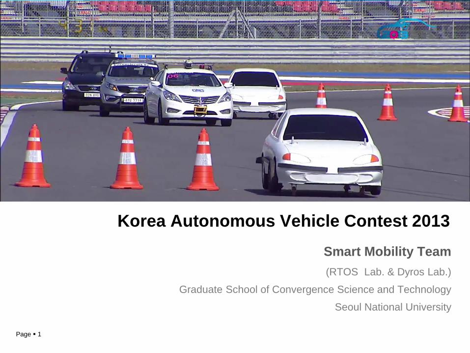
Korea Autonomous Vehicle Contest 2013 Smart Mobility Team (RTOS Lab. & Dyros Lab.)
Graduate School of Convergence Science and Technology
Seoul National University
Page 2
Contents
1. Contest Information
1-1. Introduction of the Contest
2. Technical Information 2-1. Spirit-1
2-2-1. Perception of Surroundings
1-2. Preparation for the Contest
2-2. Functional Technique
2-2-2. Localization 2-2-3. Decision 2-2-4. Path Planning & Tracking
Page 3
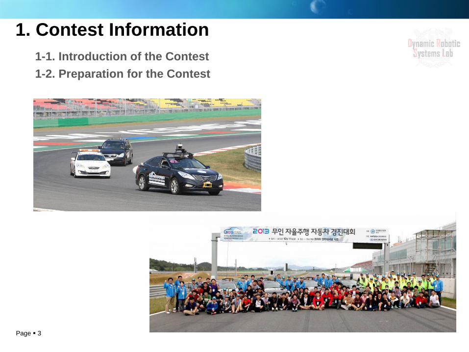
1. Contest Information 1-1. Introduction of the Contest 1-2. Preparation for the Contest
Page 4
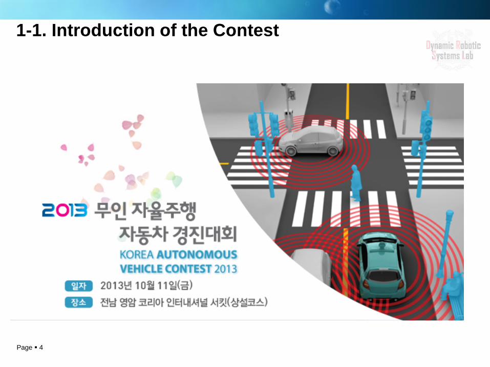
1-1. Introduction of the Contest
Page 5
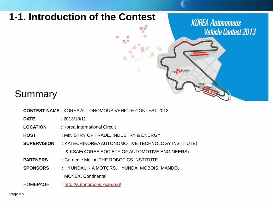
CONTEST NAME : KOREA AUTONOMOUS VEHICLE CONTEST 2013
DATE : 2013/10/11
LOCATION : Korea International Circuit
HOST : MINISTRY OF TRADE. INDUSTRY & ENERGY
SUPERVISION : KATECH(KOREA AUTONOMOTIVE TECHNOLOGY INSTITUTE)
& KSAE(KOREA SOCIETY OF AUTOMOTIVE ENGINEERS)
PARTNERS : Carnegie Mellon THE ROBOTICS INSTITUTE
SPONSORS : HYUNDAI, KIA MOTORS, HYUNDAI MOBOIS, MANDO,
MCNEX, Continental
HOMEPAGE : http://autonomous.ksae.org/
Summary
1-1. Introduction of the Contest
Page 6
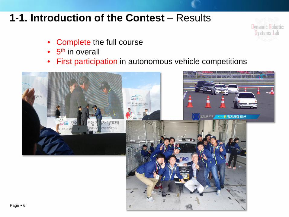
1-1. Introduction of the Contest – Results
• Complete the full course • 5th in overall • First participation in autonomous vehicle competitions
Page 7
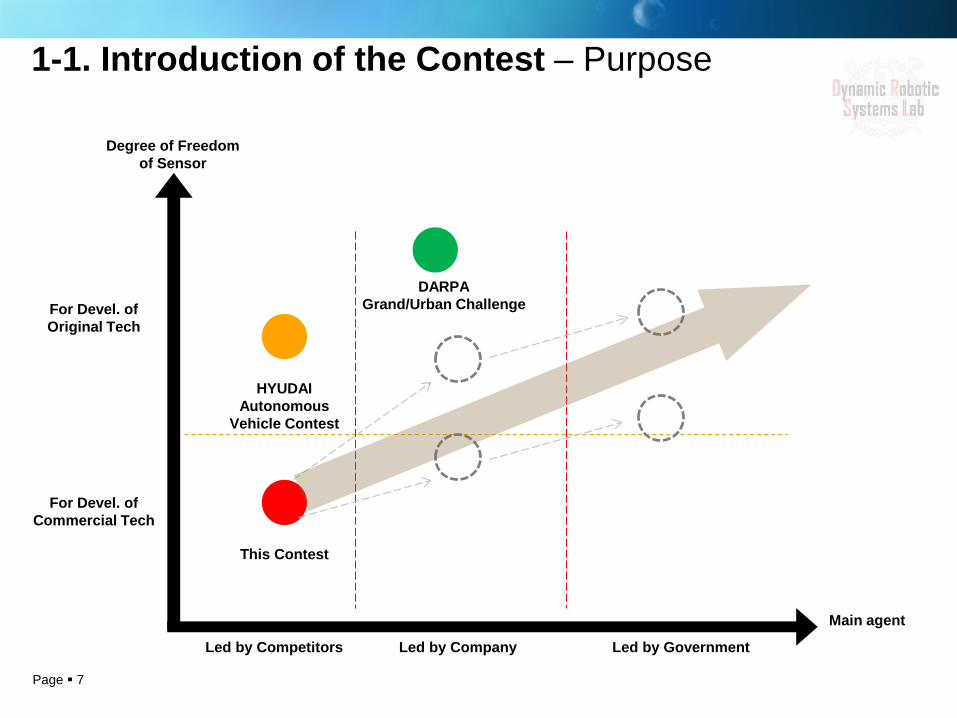
Degree of Freedom of Sensor
For Devel. of Original Tech
DARPA Grand/Urban Challenge
HYUDAI Autonomous
Vehicle Contest
For Devel. of Commercial Tech
This Contest
Led by Competitors Led by Company Led by Government
Main agent
1-1. Introduction of the Contest – Purpose
Page 8
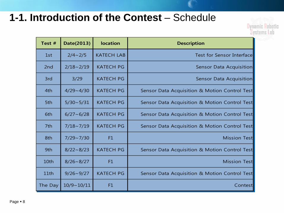
Test # Date(2013) location Description
1st 2/4~2/5 KATECH LAB Test for Sensor Interface
2nd 2/18~2/19 KATECH PG Sensor Data Acquisition
3rd 3/29 KATECH PG Sensor Data Acquisition
4th 4/29~4/30 KATECH PG Sensor Data Acquisition & Motion Control Test
5th 5/30~5/31 KATECH PG Sensor Data Acquisition & Motion Control Test
6th 6/27~6/28 KATECH PG Sensor Data Acquisition & Motion Control Test
7th 7/18~7/19 KATECH PG Sensor Data Acquisition & Motion Control Test
8th 7/29~7/30 F1 Mission Test
9th 8/22~8/23 KATECH PG Sensor Data Acquisition & Motion Control Test
10th 8/26~8/27 F1 Mission Test
11th 9/26~9/27 KATECH PG Sensor Data Acquisition & Motion Control Test
The Day 10/9~10/11 F1 Contest
1-1. Introduction of the Contest – Schedule

Page 9
1-1. Introduction of the Contest – Missions(1)
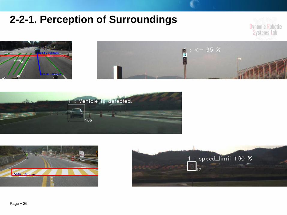
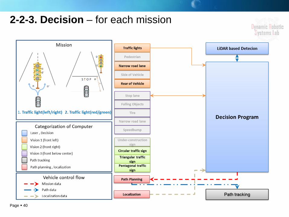
1. Recognition of a traffic light direction 2. Recognition of a traffic light signal (i.e. sign, stop and go)

Page 10
3. Falling obstacle avoidance 4. Recognition of a speed limit sign and control of the vehicle speed
1-1. Introduction of the Contest – Missions(2)
Page 11
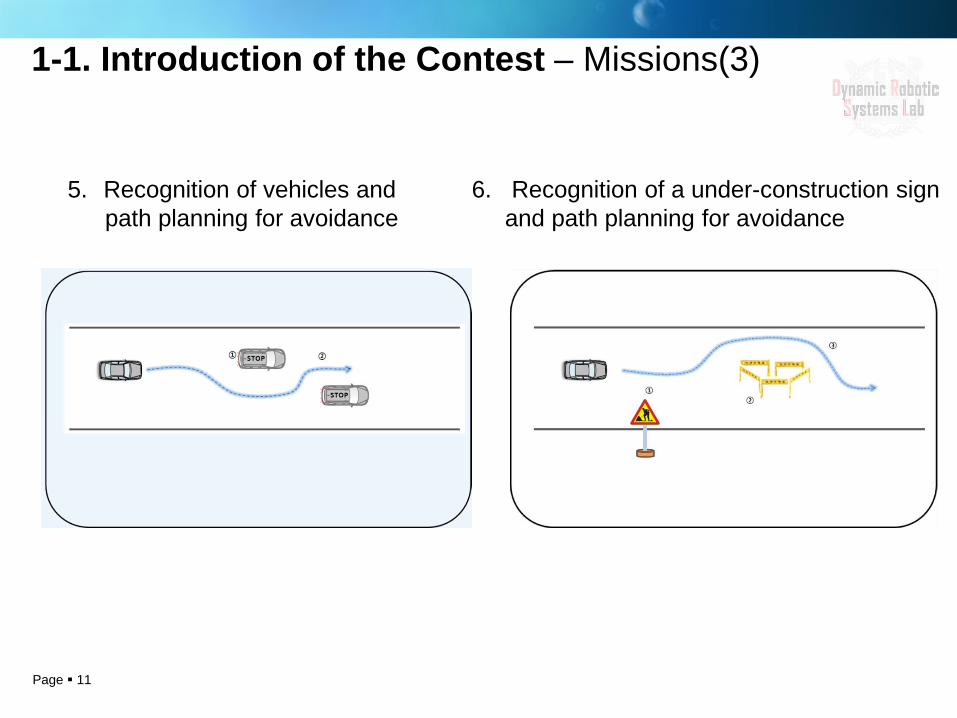
5. Recognition of vehicles and path planning for avoidance
6. Recognition of a under-construction sign and path planning for avoidance
1-1. Introduction of the Contest – Missions(3)
Page 12
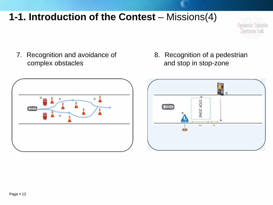
1-1. Introduction of the Contest – Missions(4)
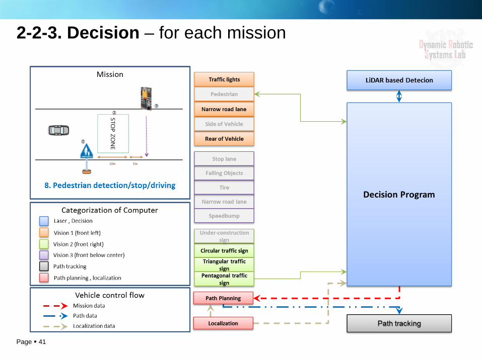
8. Recognition of a pedestrian and stop in stop-zone
7. Recognition and avoidance of complex obstacles
Page 13
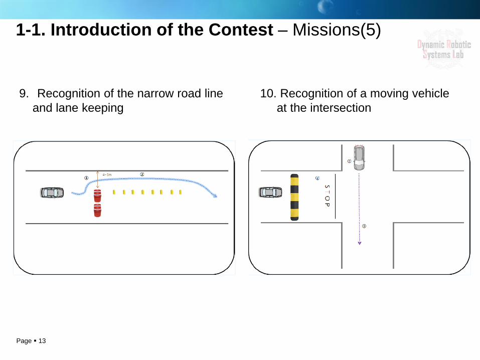
9. Recognition of the narrow road line and lane keeping
10. Recognition of a moving vehicle at the intersection
1-1. Introduction of the Contest – Missions(5)

Page 14
1-2. Preparation for the Contest
Page 15
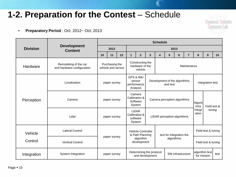
1-2. Preparation for the Contest – Schedule
Division Development
Content
Schedule
2012 2013
10 11 12 1 2 3 4 5 6 7 8 9 10
Hardware Remodeling of the car and hardware configuration
Purchasing the vehicle and sensor
Constructing the hardware of the
vehicle Maintenance
Perception
Localization paper survey
GPS & IMU sensor
performance Analysis
Development of the algorithms and test Integration test
Camera paper survey
Camera Calibration &
Software System
Camera perception algorithms Algorithms
Integration
Field test & tuning
Lidar paper survey
LiDAR Calibration &
software System
LiDAR perception algorithms
Vehicle
Control
Lateral Control
paper survey
Vehicle Controller & Path Planning
algorithm development
test for integration the algorithms
Field test & tuning
Vertical Control Field test & tuning
Integration System Integration paper survey Determining the protocol and development SW infrastructure algorithm test
for mission test
• Preparatory Period : Oct. 2012~ Oct. 2013

Page 16
1-2. Preparation for the Contest – Testing Ground
• Gwanggyo Techno-Valley in Suwon
• Eumseong New Town
• Eumseong Ggot-dong-nae
• Korea Automotive Technology Institute PG
Page 17
2. Technical Information 2-1. Spirit-1 2-2. Functional Technique
Page 18
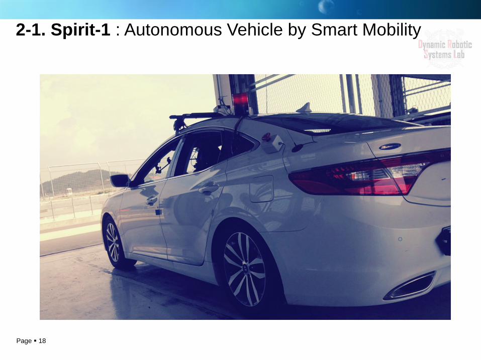
2-1. Spirit-1 : Autonomous Vehicle by Smart Mobility

Page 19
2-1-1. Hardware Information - Specification
Mono Camera (Dragonfly2) X 3 640x480, 30FPS
Lidar (LMS-511) X 2 FOV 190 Deg Range 0~80m
DGPS (B20) X 1 2DRMS 0.75m
Frequency 10Hz
Smart Actuator (IG-52GM) X 1
Hyundai HG240
MCU (ACC/BRK) X 2 LM3S8962
Industrial PC X 2 I7 3.5GHz
Laptop X 2 I7 2.3GHz
Real-time Embedded System X 1 CompactRio
Page 20
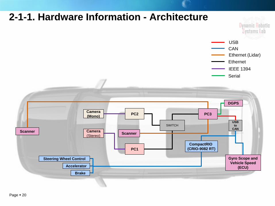
2-1-1. Hardware Information - Architecture
Camera (Stereo)
PC1
USB to
CAN
USB CAN Ethernet (Lidar)
IEEE 1394 Serial
Camera (Mono) PC2
Scanner Scanner
DGPS
CompactRIO (CRIO-9082 RT)
Ethernet
PC3
Accelerator
Brake
Steering Wheel Control Gyro Scope and Vehicle Speed
(ECU)
SWITCH
Page 21
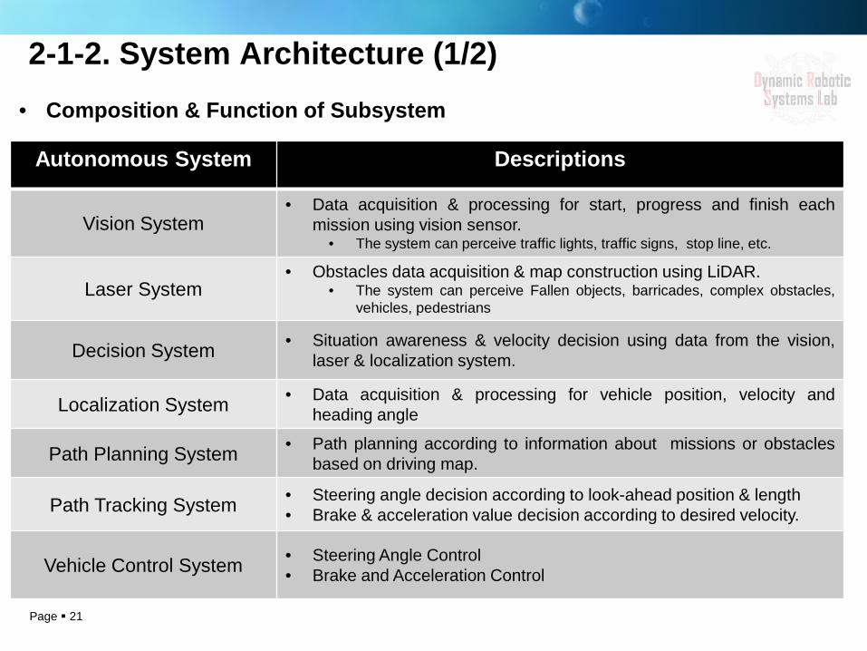
2-1-2. System Architecture (1/2)
Autonomous System Descriptions
Vision System • Data acquisition & processing for start, progress and finish each
mission using vision sensor. • The system can perceive traffic lights, traffic signs, stop line, etc.
Laser System • Obstacles data acquisition & map construction using LiDAR.
• The system can perceive Fallen objects, barricades, complex obstacles, vehicles, pedestrians
Decision System • Situation awareness & velocity decision using data from the vision, laser & localization system.
Localization System • Data acquisition & processing for vehicle position, velocity and heading angle
Path Planning System • Path planning according to information about missions or obstacles based on driving map.
Path Tracking System • Steering angle decision according to look-ahead position & length • Brake & acceleration value decision according to desired velocity.
Vehicle Control System • Steering Angle Control • Brake and Acceleration Control
• Composition & Function of Subsystem
Page 22
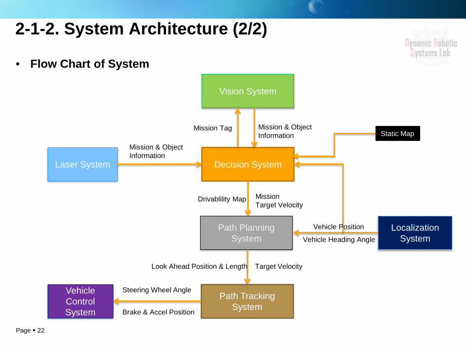
• Flow Chart of System
Decision System
Vision System
Mission & Object Information
Mission Tag
Mission Target Velocity
Drivablility Map
Path Planning System
Localization System Vehicle Heading Angle
Look Ahead Position & Length Target Velocity
Path Tracking System Brake & Accel Position
Steering Wheel Angle Vehicle Control System
Static Map
Vehicle Position
Laser System
Mission & Object Information
2-1-2. System Architecture (2/2)
Page 23
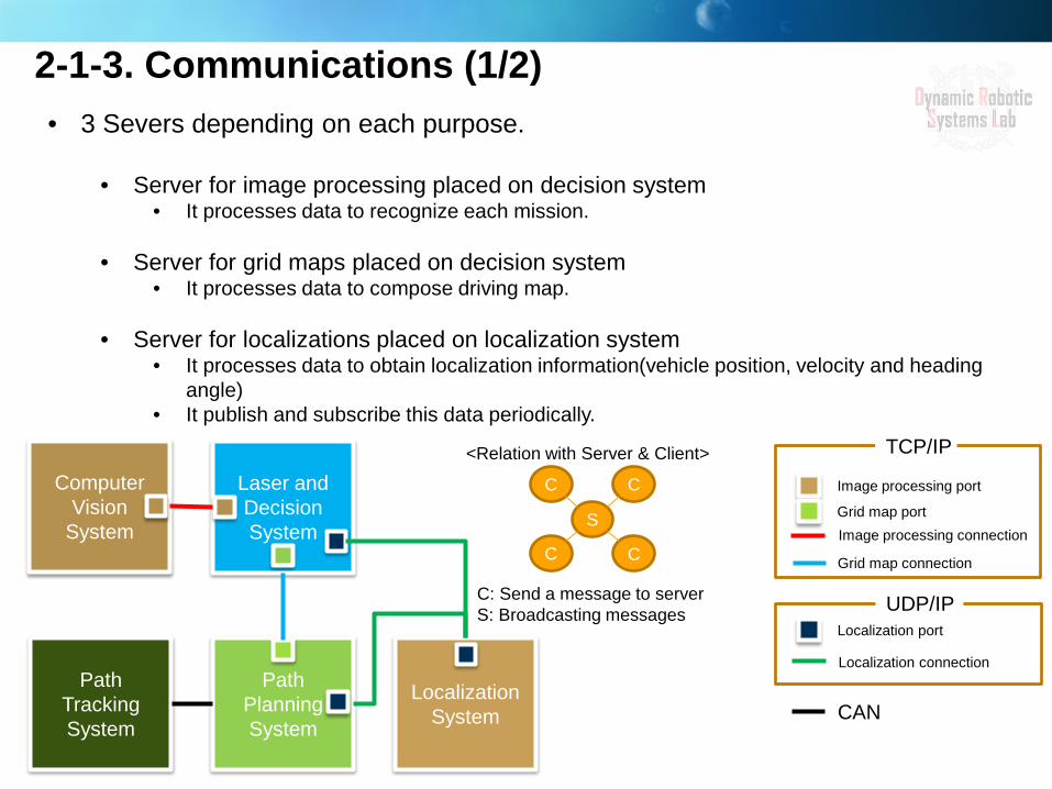
• 3 Severs depending on each purpose.
• Server for image processing placed on decision system • It processes data to recognize each mission.
• Server for grid maps placed on decision system
• It processes data to compose driving map.
• Server for localizations placed on localization system • It processes data to obtain localization information(vehicle position, velocity and heading
angle) • It publish and subscribe this data periodically.
Image processing connection
Image processing port
CAN
Grid map port
Localization port
Grid map connection
Localization connection
TCP/IP
UDP/IP
Path Planning System
Path Tracking System
Localization System
Computer Vision
System
Laser and Decision System
C
S
C
C C
C: Send a message to server S: Broadcasting messages
<Relation with Server & Client>
2-1-3. Communications (1/2)

Page 24
2-1-3. Communications (2/2) • Block Diagram of Subsystems for Communications

Page 25
2-1. Functional Technique
Perception
Path Planning
Vehicle Control
Localization
Page 26
2-2-1. Perception of Surroundings
Page 27
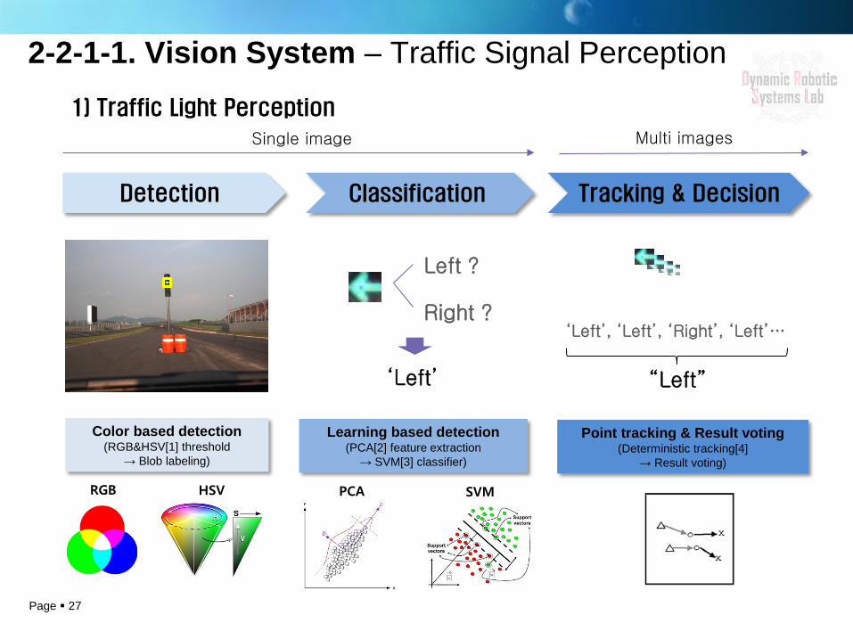
2-2-1-1. Vision System – Traffic Signal Perception
1) Traffic Light Perception
Detection
‘Left’
Classification
Left ?
Right ?
Tracking & Decision
‘Left’, ‘Left’, ‘Right’, ‘Left’…
“Left”
Single image Multi images
Color based detection (RGB&HSV[1] threshold
→ Blob labeling)
Learning based detection (PCA[2] feature extraction
→ SVM[3] classifier)
Point tracking & Result voting (Deterministic tracking[4]
→ Result voting)
PCA SVM RGB HSV
Page 28
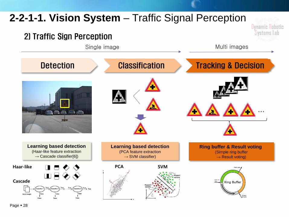
2-2-1-1. Vision System – Traffic Signal Perception 2) Traffic Sign Perception
Detection Classification Tracking & Decision
…
Single image Multi images
Learning based detection (Haar-like feature extraction
→ Cascade classifier[6])
Learning based detection (PCA feature extraction
→ SVM classifier)
Ring buffer & Result voting (Simple ring buffer → Result voting)
PCA SVM Haar-like
Cascade
Page 29
2-2-1-1. Vision System – Traffic Signal Perception
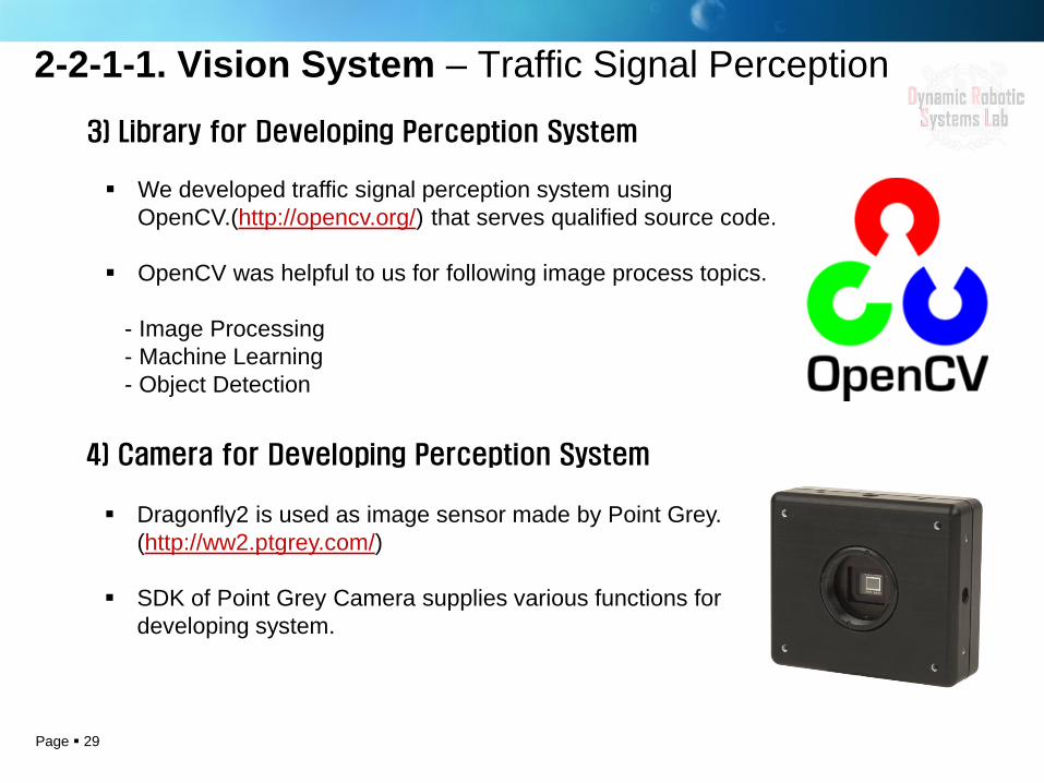
3) Library for Developing Perception System
We developed traffic signal perception system using OpenCV.(http://opencv.org/) that serves qualified source code.
OpenCV was helpful to us for following image process topics. - Image Processing - Machine Learning - Object Detection
4) Camera for Developing Perception System
Dragonfly2 is used as image sensor made by Point Grey. (http://ww2.ptgrey.com/)
SDK of Point Grey Camera supplies various functions for developing system.
Page 30 30
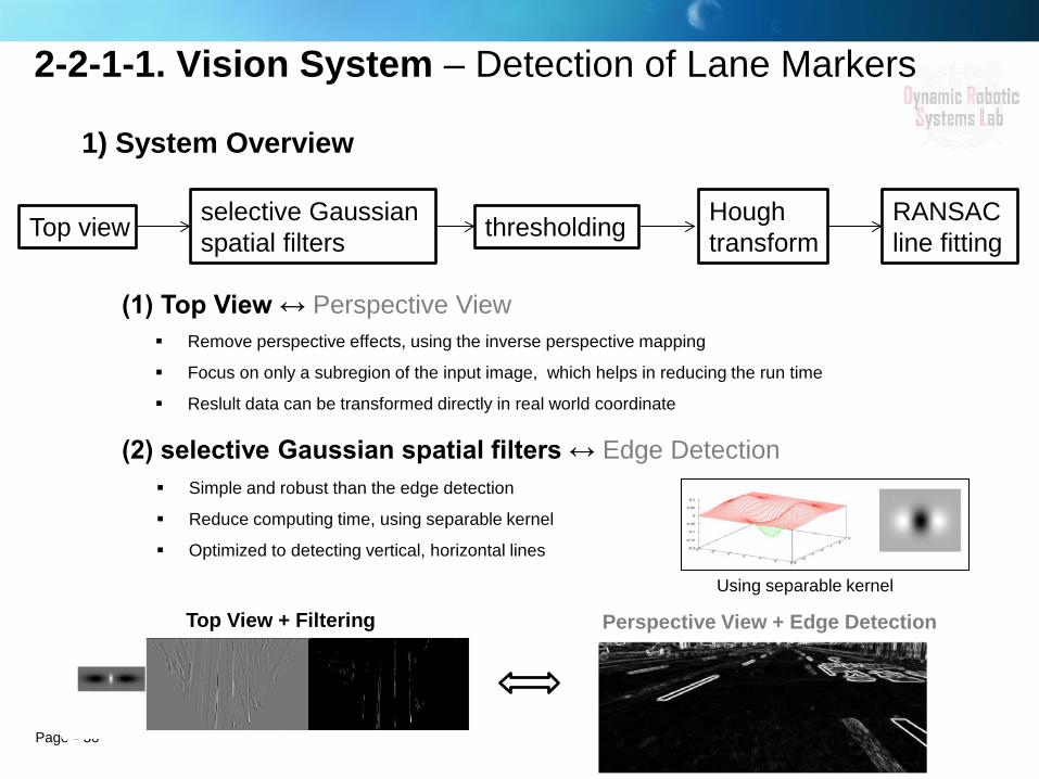
1) System Overview
Top view selective Gaussian spatial filters thresholding Hough
transform RANSAC line fitting
(1) Top View ↔ Perspective View
(2) selective Gaussian spatial filters ↔ Edge Detection
Using separable kernel
Top View + Filtering Perspective View + Edge Detection
2-2-1-1. Vision System – Detection of Lane Markers
Remove perspective effects, using the inverse perspective mapping
Focus on only a subregion of the input image, which helps in reducing the run time
Reslult data can be transformed directly in real world coordinate
Simple and robust than the edge detection
Reduce computing time, using separable kernel
Optimized to detecting vertical, horizontal lines
Page 31 31
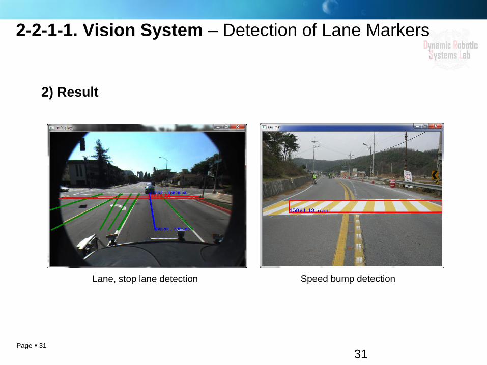
2) Result
Lane, stop lane detection Speed bump detection
2-2-1-1. Vision System – Detection of Lane Markers
Page 32
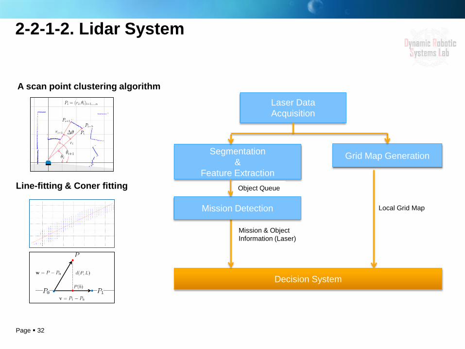
2-2-1-2. Lidar System
Laser Data Acquisition
Grid Map Generation Segmentation &
Feature Extraction
Local Grid Map
Decision System
Mission & Object Information (Laser)
Mission Detection
Object Queue
A scan point clustering algorithm
Line-fitting & Coner fitting

Page 33
2-2-1. Perception of Surroundings – Reference
[1] HSV color space : http://en.wikipedia.org/wiki/HSL_and_HSV
[2] PCA (with regard to face recognition) :http://docs.opencv.org/modules/contrib/doc/facerec/facerec_tutorial.html?highlight=eigenface
[3] SVM : http://docs.opencv.org/doc/tutorials/ml/introduction_to_svm/introduction_to_svm.html?highlight=svm
[4] Deterministic tracking : A. Yilmaz, O. Javed, and M. Shah, “Object tracking: A survey,” ACM Comput. Surv., vol. 38, no. 4, pp. 1–45, 2006.
[5] Cascade Classification & Haar-like feature :http://docs.opencv.org/modules/objdetect/doc/cascade_classification.html?highlight=viola%20jones
[6] Lane Detection : http://vision.caltech.edu/malaa/software/research/caltech-lane-detection/
[7] Camera – Laser Calibration : http://www-personal.acfr.usyd.edu.au/akas9185/
Page 34
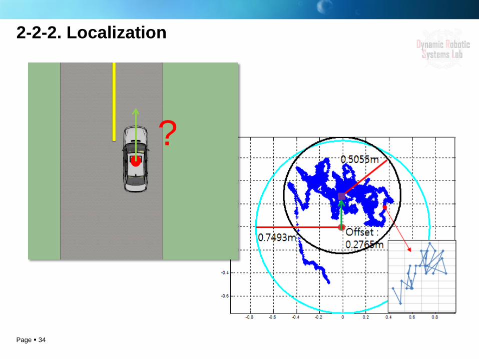
2-2-2. Localization
?

Page 35
Output Data Computation
Sensor Data Processing
Velocity Computation
DGPS Data
Processing Latitude, Longitude
Kalman Filter I
Heading Angle
Conversion
Heading Angle Prediction
Gyroscope Data
Processing
Heading Angle Update
Yaw Rate Heading Angle
Heading Angle
Heading Angle
Coordinate Conversion (GRS-TM) (X, Y)
Kalman Filter II
Position Conversion
Position Update
Position Prediction
Velocity (X, Y) (X, Y) Wheel Speed Data
Processing
Flow: Input Processing
• Compensation the Yaw rate offset
• Analyze NMEA protocol
• Revise OBD II velocity
Prediction • Predict heading angle using
integration the Yaw rate (100Hz) • Predict the position using
integration Velocity (50Hz)
Update • Update GPS heading
angle (10Hz) • Update GPS position
(10Hz)
Output Computation • Transformation Path
planning/tracking coordinate
2-2-2. Localization - Overview
Page 36
175
176
177
178
179
180
181
0 1 2 3 4 5
Hea
ding
Ang
le
(deg
ree)
Time (s)
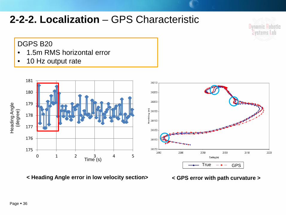
DGPS B20 • 1.5m RMS horizontal error • 10 Hz output rate
< Heading Angle error in low velocity section>
GPS True
< GPS error with path curvature >
2-2-2. Localization – GPS Characteristic
Page 37
Aver
age
head
ing
erro
r (d
egre
e)
Yaw rate (degree/s)
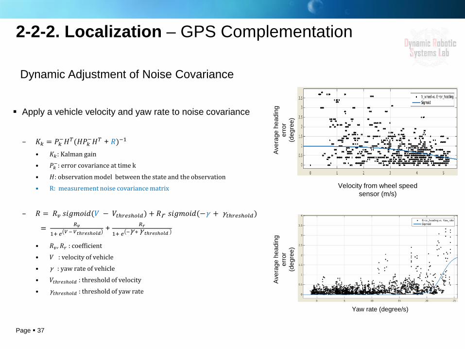
Dynamic Adjustment of Noise Covariance
Apply a vehicle velocity and yaw rate to noise covariance
– 𝐾𝑘 = 𝑃𝑘−𝐻𝑇(𝐻𝑃𝑘−𝐻𝑇 + 𝑅)−1
• 𝐾𝑘: Kalman gain • 𝑃𝑘−: error covariance at time k
• 𝐻: observation model between the state and the observation
• R: measurement noise covariance matrix
– 𝑅 = 𝑅𝑣 𝑠𝑠𝑠𝑠𝑠𝑠𝑠(𝑉 − 𝑉𝑡𝑡𝑡𝑡𝑡𝑡𝑡𝑡𝑡) + 𝑅r 𝑠𝑠𝑠𝑠𝑠𝑠𝑠(−γ + γ𝑡𝑡𝑡𝑡𝑡𝑡𝑡𝑡𝑡)
= 𝑅𝑣1+ 𝑡 𝑉 − 𝑉𝑡𝑡𝑡𝑡𝑡𝑡𝑡𝑡𝑡
+ 𝑅𝑡1+ 𝑡 −γ + γ 𝑡𝑡𝑡𝑡𝑡𝑡𝑡𝑡𝑡
• 𝑅𝑣 , 𝑅𝑡 : coefficient
• 𝑉 : velocity of vehicle
• γ : yaw rate of vehicle
• 𝑉𝑡𝑡𝑡𝑡𝑡𝑡𝑡𝑡𝑡 : threshold of velocity
• γ𝑡𝑡𝑡𝑡𝑡𝑡𝑡𝑡𝑡 : threshold of yaw rate
Aver
age
head
ing
erro
r (d
egre
e)
Velocity from wheel speed sensor (m/s)
2-2-2. Localization – GPS Complementation
Page 38
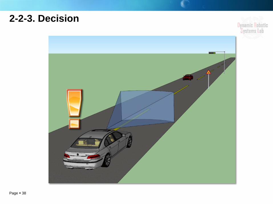
2-2-3. Decision
Page 39
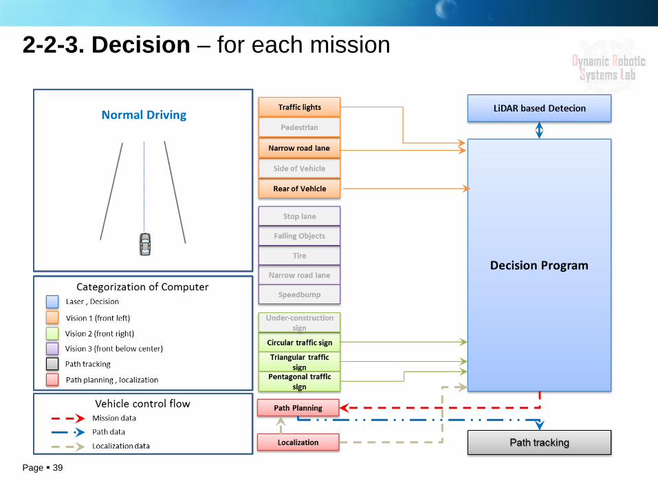
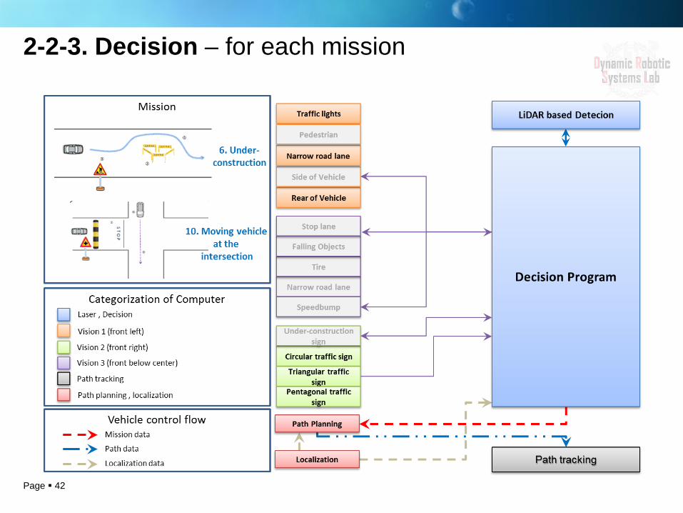
2-2-3. Decision – for each mission
Page 40
2-2-3. Decision – for each mission
Page 41
2-2-3. Decision – for each mission
Page 42
2-2-3. Decision – for each mission
Page 43
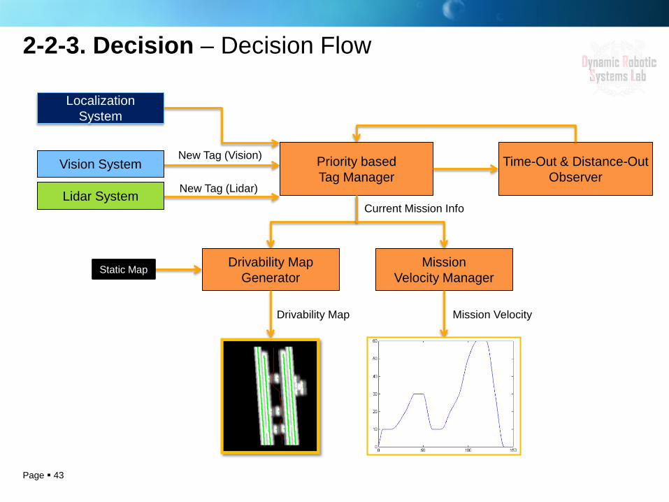
Priority based Tag Manager
Mission Velocity Manager
New Tag (Vision)
New Tag (Lidar)
Drivability Map Generator
Time-Out & Distance-Out Observer
Current Mission Info
Mission Velocity Drivability Map
Vision System
Lidar System
Static Map
Localization System
2-2-3. Decision – Decision Flow
Page 44
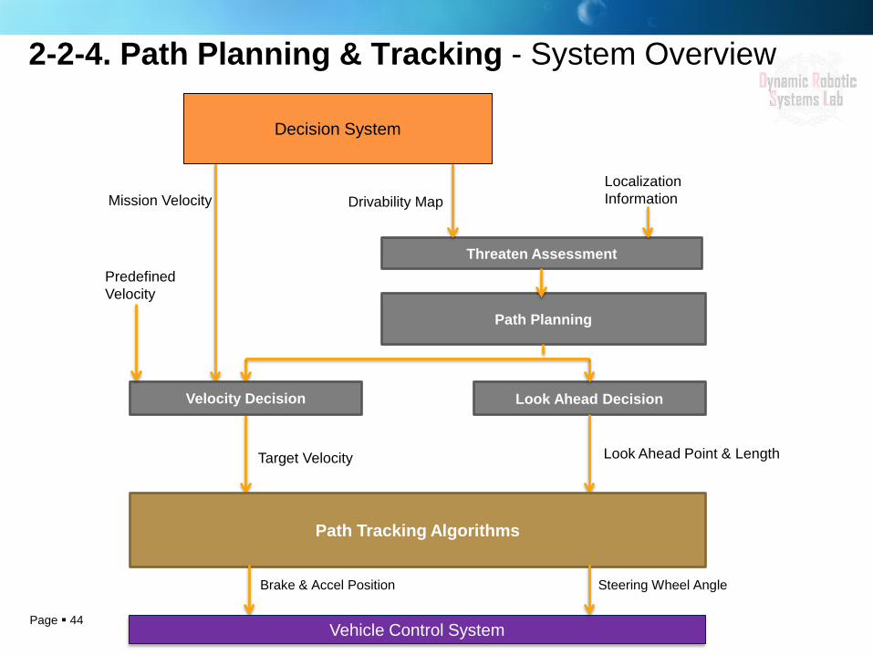
2-2-4. Path Planning & Tracking - System Overview
Drivability Map Localization Information
Threaten Assessment
Path Planning
Look Ahead Decision
Look Ahead Point & Length Target Velocity
Mission Velocity
Velocity Decision
Predefined Velocity
Path Tracking Algorithms
Decision System
Brake & Accel Position Steering Wheel Angle
Vehicle Control System
Page 45
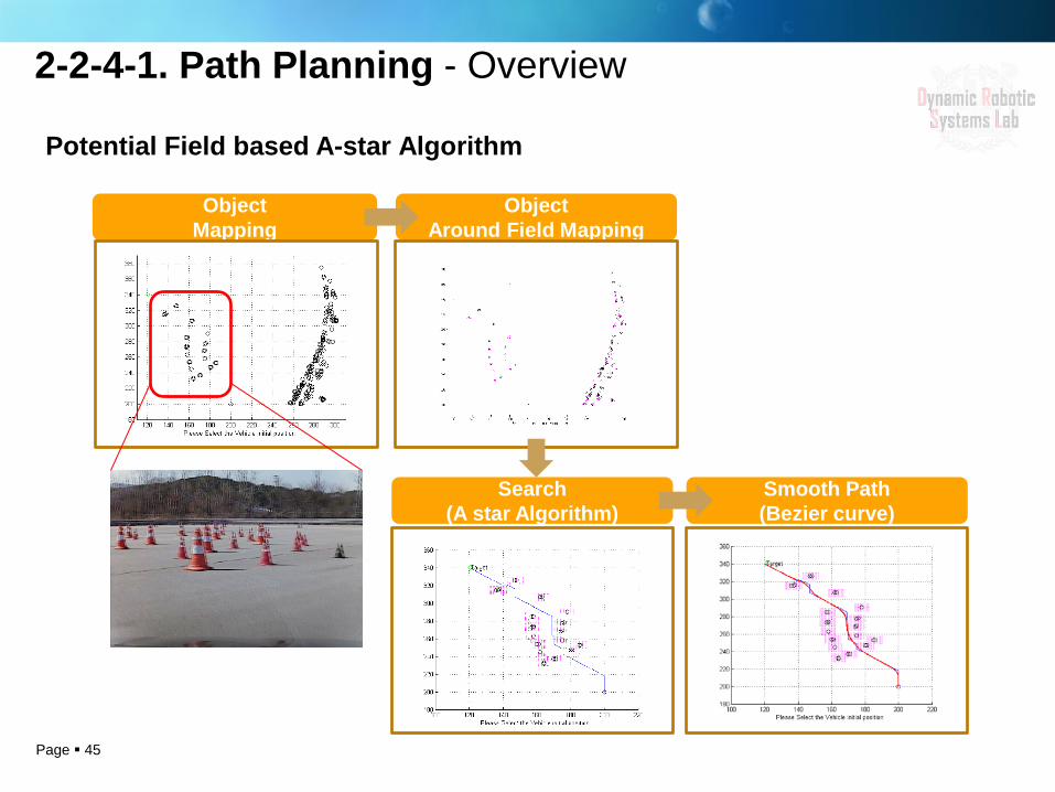
2-2-4-1. Path Planning - Overview
Potential Field based A-star Algorithm
Object Mapping
Object Around Field Mapping
Search (A star Algorithm)
Smooth Path (Bezier curve)
Page 46
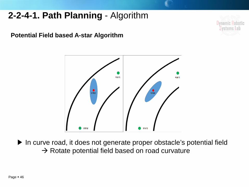
Potential Field based A-star Algorithm
2-2-4-1. Path Planning - Algorithm
▶ In curve road, it does not generate proper obstacle’s potential field Rotate potential field based on road curvature

Page 47
Pure pursuit Stanley Vector Pure pursuit
It considers orientation tracking. Vehicle’s orientation affects significantly steering angle.
Inflection region like intersection region is vulnerable because of selecting the nearest point with front wheel point
It tracks look ahead point . It doesn’t take into account look ahead point’s orientation.
2-2-4-2. Path Tracking - Candidates of Algorithm
Page 48
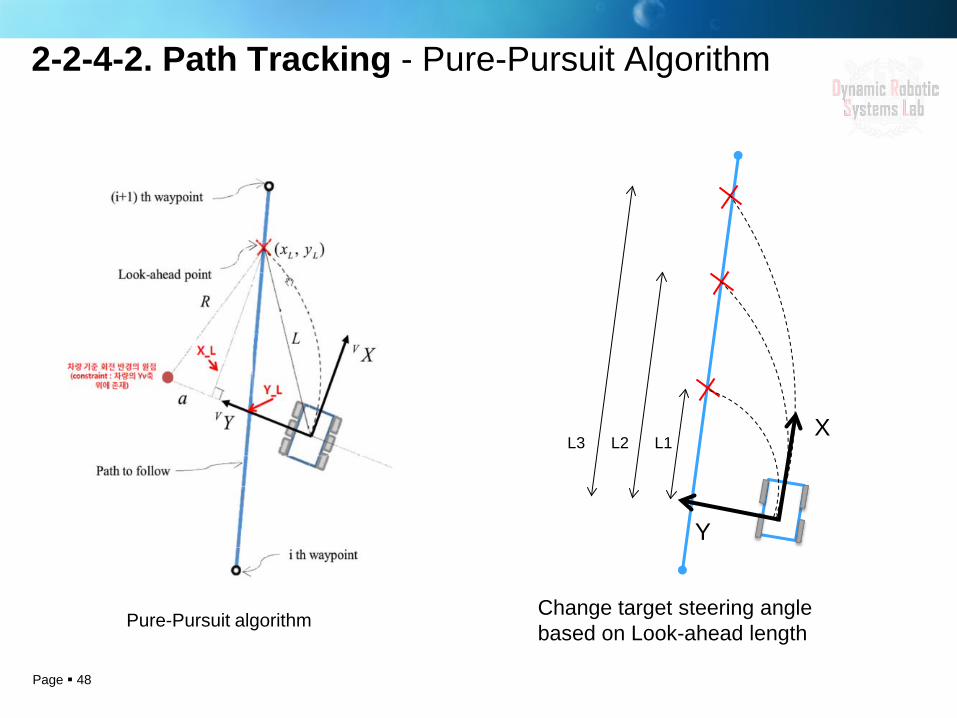
2-2-4-2. Path Tracking - Pure-Pursuit Algorithm
Change target steering angle based on Look-ahead length
X
Y
L3 L1 L2
Pure-Pursuit algorithm
Page 49
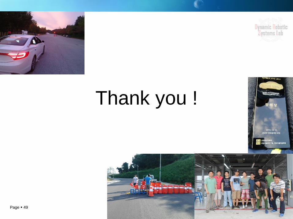
Thank you !
Recommended