QIN-POWERED INSTRUMENT ENGINE USER MANUAL
QIN-POWERED INSTRUMENT USER MANUAL
I
Table of Contents
Chapter One: The Interface ............................................................................................................................. 1
1.1 Main Interface ........................................................................................................................................ 1
1.1.1 Instrument List (1) ...................................................................................................... 1
1.1.2 Instrument Edit Zone (2) ............................................................................................. 2
1.1.3 Effects List and Effects Zone (3A, 3B) ........................................................................ 2
1.1.4 MIDI Keyboard (4) ...................................................................................................... 2
1.2 About ........................................................................................................................................................ 3
1.3 User Interface ......................................................................................................................................... 3
1.3.1 Main Interface ............................................................................................................ 3
1.3.2 Layers Editor .............................................................................................................. 6
1.3.3 Subset Editor ............................................................................................................. 6
1.3.4 Keymaps Editor .......................................................................................................... 7
1.3.5 Extenders Interface .................................................................................................... 8
Chapter 2: The Basics .................................................................................................................................... 10
2.1 Using the Presets ................................................................................................................................ 10
2.2 Using the Subsets ............................................................................................................................... 10
2.3 Delay & Reverb (FX) .......................................................................................................... 10
2.4 Filters & Distortion (FX) ...................................................................................................... 11
2.5 Techniques ............................................................................................................................................ 12
Chapter Three: The Extenders ..................................................................................................................... 13
3.1 General Extenders .............................................................................................................................. 13
3.1.1 KeySwitch ................................................................................................................ 13
3.1.2 KeySwitch 2 ............................................................................................................. 14
3.1.3 KeySwitch 3 ............................................................................................................. 15
3.1.4 Program Change ...................................................................................................... 17
3.1.5 Mod Wheel ............................................................................................................... 18
3.1.6 Legato Assignment................................................................................................... 19
3.1.7 Automatic Select ...................................................................................................... 20
3.1.8 Speed Detection ....................................................................................................... 21
3.1.9 Round-Robin ............................................................................................................ 22
3.1.10 Release Trigger ...................................................................................................... 23
3.1.11 After Touch ............................................................................................................. 24
3.1.12 Delayed Trigger ...................................................................................................... 25
3.1.13 One Shot ................................................................................................................ 25
3.1.14 Erratic Range Control (E.R.C.) ............................................................................... 26
3.1.15 Micro Tuning .......................................................................................................... 26
3.2 Subset Extenders ................................................................................................................................ 27
3.2.1 Amplitude Envelope ................................................................................................. 27
3.2.2 Sub-Layer Layout (SLL) ........................................................................................... 28
3.2.3 Pitch Envelope ......................................................................................................... 29
3.3 Special Extenders ................................................................................................................................ 29
3.3.1 Multi MIDI and Audio Channel .................................................................................. 30
QIN-POWERED INSTRUMENT ENGINE USER MANUAL
QIN-POWERED INSTRUMENT USER MANUAL
II
Chapter Four: Combining the Extenders .................................................................................................. 31
4.1 Speed Detection and Legato ............................................................................................................. 31
Chapter Five: Product Authorization .......................................................................................................... 33
5.1 How to Authorize the Instrument ...................................................................................................... 33
5.1.1 Getting Your User ID ................................................................................................ 33
5.1.2 Product Authorization ............................................................................................... 33
5.2 Authorization Mechanism ................................................................................................................... 34
5.2.1 User ID .................................................................................................................... 34
5.2.2 Serial Code .............................................................................................................. 34
5.2.3 User Name ............................................................................................................... 34
5.2.4 Sound Decryption .................................................................................................... 35
5.2.5 Noise Burst .............................................................................................................. 35
5.2.6 Successful Authorization .......................................................................................... 35
5.3 FAQ ........................................................................................................................................................ 35
QIN-POWERED INSTRUMENT ENGINE USER MANUAL
QIN-POWERED INSTRUMENT USER MANUAL
III
Definitions:
Subset: A subset is the basic building block of a QIN instrument's sound, and it is what you access as a whole
unit for further editing inside the QIN. It is a pre-mapped sample unit installed by the soundbank installer. A
subset’s file extension is *.KAS.
Extenders (Ext): Extenders are one of several kinds of modules that extend the functions of a plugin, and can
be loaded or unloaded as needed. Some advanced interactive results can be achieved by combining extenders .
Special Thanks:
Additional Manual Editing: Don Rechtman

QIN-POWERED INSTRUMENT ENGINE USER MANUAL
QIN-POWERED INSTRUMENT USER MANUAL
IV
QIN-POWERED INSTRUMENT ENGINE USER MANUAL
QIN-POWERED INSTRUMENT USER MANUAL
1
Chapter One: The Interface
1.1 Main Interface
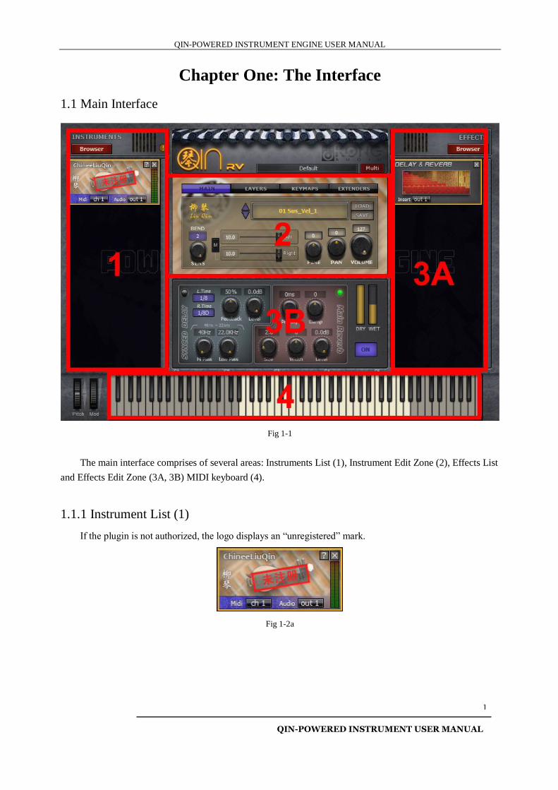
Fig 1-1
The main interface comprises of several areas: Instruments List (1), Instrument Edit Zone (2), Effects List
and Effects Edit Zone (3A, 3B) MIDI keyboard (4).
1.1.1 Instrument List (1)
If the plugin is not authorized, the logo displays an “unregistered” mark.
Fig 1-2a
QIN-POWERED INSTRUMENT ENGINE USER MANUAL
QIN-POWERED INSTRUMENT USER MANUAL
2
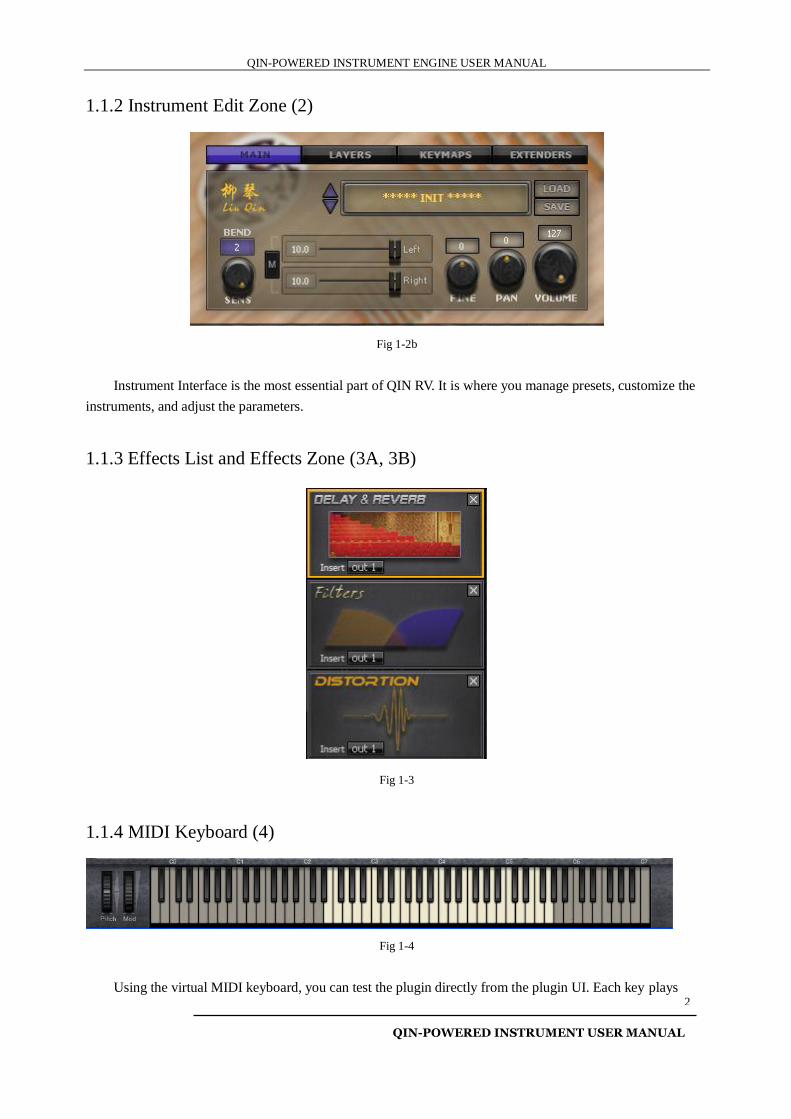
1.1.2 Instrument Edit Zone (2)
Fig 1-2b
Instrument Interface is the most essential part of QIN RV. It is where you manage presets, customize the
instruments, and adjust the parameters.
1.1.3 Effects List and Effects Zone (3A, 3B)
Fig 1-3
1.1.4 MIDI Keyboard (4)
Fig 1-4
Using the virtual MIDI keyboard, you can test the plugin directly from the plugin UI. Each key plays
QIN-POWERED INSTRUMENT ENGINE USER MANUAL
QIN-POWERED INSTRUMENT USER MANUAL
3
louder (velocity responsive) the closer to the edge it is clicked vertically. The lowest key is C1.
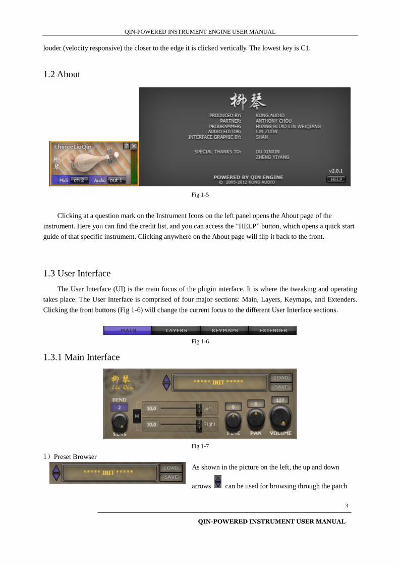
1.2 About
Fig 1-5
Clicking at a question mark on the Instrument Icons on the left panel opens the About page of the
instrument. Here you can find the credit list, and you can access the “HELP” button, which opens a quick start
guide of that specific instrument. Clicking anywhere on the About page will flip it back to the front.
1.3 User Interface
The User Interface (UI) is the main focus of the plugin interface. It is where the tweaking and operating
takes place. The User Interface is comprised of four major sections: Main, Layers, Keymaps, and Extenders.
Clicking the front buttons (Fig 1-6) will change the current focus to the different User Interface sections.
Fig 1-6
1.3.1 Main Interface
Fig 1-7
1)Preset Browser
As shown in the picture on the left, the up and down
arrows can be used for browsing through the patch
QIN-POWERED INSTRUMENT ENGINE USER MANUAL
QIN-POWERED INSTRUMENT USER MANUAL
4
list and selecting a patch. Click or to load or save an FXP format VST patch file.
2)Pitch Bend:
Click the color frame to access the pop-up menu. The default value is 2, which means the pitch bend
range is a whole tone (whole step) higher or lower.
NOTE: Each integer represents the maximum pitch bend in chromatic scale half steps (semi-tones); thus the pitch bend
may be set anywhere from zero to a half step (1) to an octave (12).
3)Velocity Sensitivity:
This knob controls the velocity sensitivity of the plugin. The default is the max value of 127. This
parameter can be controlled by MIDI CC #3.
4)L/R Channel Volume:
Click to toggle the Mono mode on and off. The “LEFT” and “RIGHT”
sliders can be controlled by MIDI CC #4 and #5. When the plugin is in the
Multi Output mode, these two parameters are disabled.
5)Main Fine-tuning:
The Main Fine-tuning’s pitch range is from +50% to -50%. This parameter can be controlled by
MIDI CC #2. When the plugin is not in the Multi Output mode, it can also be controlled by MIDI
CC #54. Click the knob and drag up and down to change the range; double-click the knob to reset it
to zero.
NOTE: The total amount of fine-tuning is the total of the Main Fine-tuning knob plus each subset's own fine-tuning settings,
ranging from - 100% to +100%. If the “Micro Tuning” extender is activated, then the total amount of the fine-tuning includes the
Micro Tuning too, so the total range would be from - 150% to +150%.
6)Main Panning:
The parameter can be controlled by MIDI CC #10. It is not functional in the Multi Output mode, as
each subset will be controlled by the MIDI CC #10 on each MIDI channel, and there will be
corresponding knobs for each subset on the User Interface. Click the knob and drag up and down to
change the range; double-click the knob to reset it to zero.
7)Main Volume:
The parameter can be controlled by MIDI CC #7. It is not functional in the Multi Output mode, as
QIN-POWERED INSTRUMENT ENGINE USER MANUAL
QIN-POWERED INSTRUMENT USER MANUAL
5
each subset will be controlled by the MIDI CC #7 on each MIDI channel. (See Section 1.3.2 “Layers Editor”)
Click the knob and drag up and down to change the range.
QIN-POWERED INSTRUMENT ENGINE USER MANUAL
QIN-POWERED INSTRUMENT USER MANUAL
6
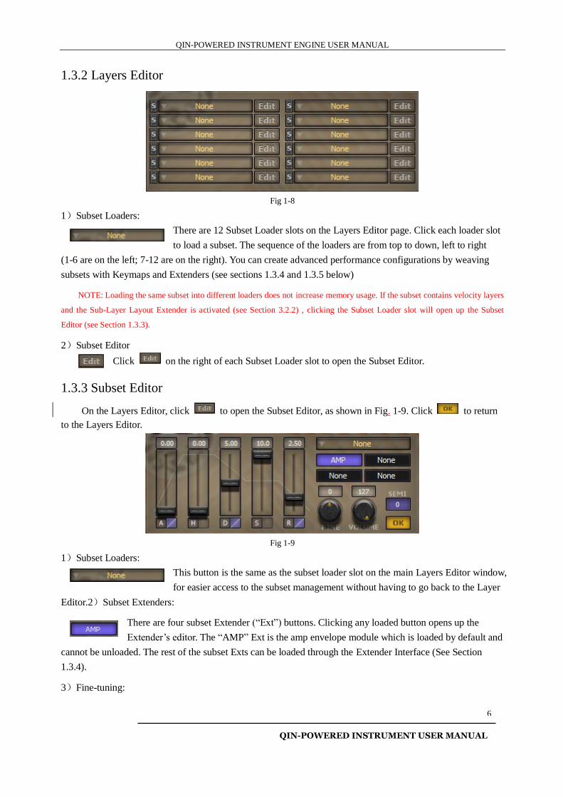
1.3.2 Layers Editor
Fig 1-8
1)Subset Loaders:
There are 12 Subset Loader slots on the Layers Editor page. Click each loader slot
to load a subset. The sequence of the loaders are from top to down, left to right
(1-6 are on the left; 7-12 are on the right). You can create advanced performance configurations by weaving
subsets with Keymaps and Extenders (see sections 1.3.4 and 1.3.5 below)
NOTE: Loading the same subset into different loaders does not increase memory usage. If the subset contains velocity layers
and the Sub-Layer Layout Extender is activated (see Section 3.2.2) , clicking the Subset Loader slot will open up the Subset
Editor (see Section 1.3.3).
2)Subset Editor
Click on the right of each Subset Loader slot to open the Subset Editor.
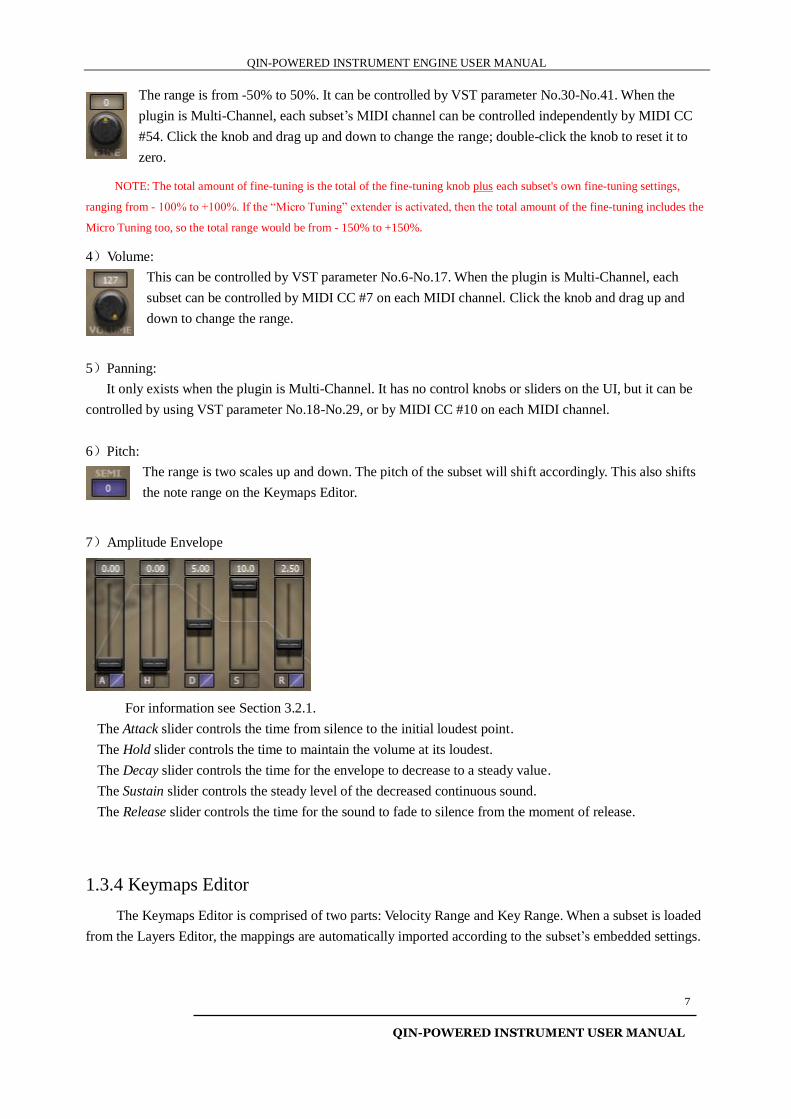
1.3.3 Subset Editor
On the Layers Editor, click to open the Subset Editor, as shown in Fig. 1-9. Click to return
to the Layers Editor.
Fig 1-9
1)Subset Loaders:
This button is the same as the subset loader slot on the main Layers Editor window,
for easier access to the subset management without having to go back to the Layer
Editor.2)Subset Extenders:
There are four subset Extender (“Ext”) buttons. Clicking any loaded button opens up the
Extender’s editor. The “AMP” Ext is the amp envelope module which is loaded by default and
cannot be unloaded. The rest of the subset Exts can be loaded through the Extender Interface (See Section
1.3.4).
3)Fine-tuning:
QIN-POWERED INSTRUMENT ENGINE USER MANUAL
QIN-POWERED INSTRUMENT USER MANUAL
7
The range is from -50% to 50%. It can be controlled by VST parameter No.30-No.41. When the
plugin is Multi-Channel, each subset’s MIDI channel can be controlled independently by MIDI CC
#54. Click the knob and drag up and down to change the range; double-click the knob to reset it to
zero.
NOTE: The total amount of fine-tuning is the total of the fine-tuning knob plus each subset's own fine-tuning settings,
ranging from - 100% to +100%. If the “Micro Tuning” extender is activated, then the total amount of the fine-tuning includes the
Micro Tuning too, so the total range would be from - 150% to +150%.
4)Volume:
This can be controlled by VST parameter No.6-No.17. When the plugin is Multi-Channel, each
subset can be controlled by MIDI CC #7 on each MIDI channel. Click the knob and drag up and
down to change the range.
5)Panning:
It only exists when the plugin is Multi-Channel. It has no control knobs or sliders on the UI, but it can be
controlled by using VST parameter No.18-No.29, or by MIDI CC #10 on each MIDI channel.
6)Pitch:
The range is two scales up and down. The pitch of the subset will shift accordingly. This also shifts
the note range on the Keymaps Editor.
7)Amplitude Envelope
For information see Section 3.2.1.
The Attack slider controls the time from silence to the initial loudest point.
The Hold slider controls the time to maintain the volume at its loudest.
The Decay slider controls the time for the envelope to decrease to a steady value.
The Sustain slider controls the steady level of the decreased continuous sound.
The Release slider controls the time for the sound to fade to silence from the moment of release.
1.3.4 Keymaps Editor
The Keymaps Editor is comprised of two parts: Velocity Range and Key Range. When a subset is loaded
from the Layers Editor, the mappings are automatically imported according to the subset’s embedded settings.
QIN-POWERED INSTRUMENT ENGINE USER MANUAL
QIN-POWERED INSTRUMENT USER MANUAL
8
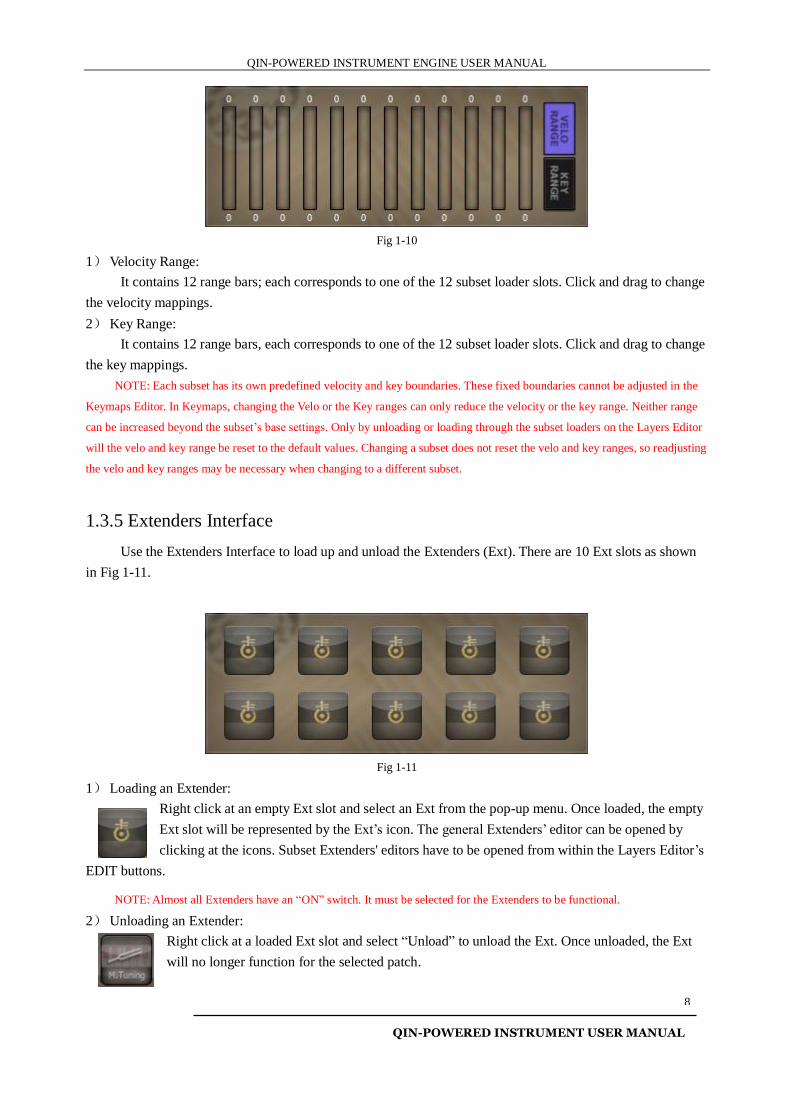
Fig 1-10
1) Velocity Range:
It contains 12 range bars; each corresponds to one of the 12 subset loader slots. Click and drag to change
the velocity mappings.
2) Key Range:
It contains 12 range bars, each corresponds to one of the 12 subset loader slots. Click and drag to change
the key mappings.
NOTE: Each subset has its own predefined velocity and key boundaries. These fixed boundaries cannot be adjusted in the
Keymaps Editor. In Keymaps, changing the Velo or the Key ranges can only reduce the velocity or the key range. Neither range
can be increased beyond the subset’s base settings. Only by unloading or loading through the subset loaders on the Layers Editor
will the velo and key range be reset to the default values. Changing a subset does not reset the velo and key ranges, so readjusting
the velo and key ranges may be necessary when changing to a different subset.
1.3.5 Extenders Interface
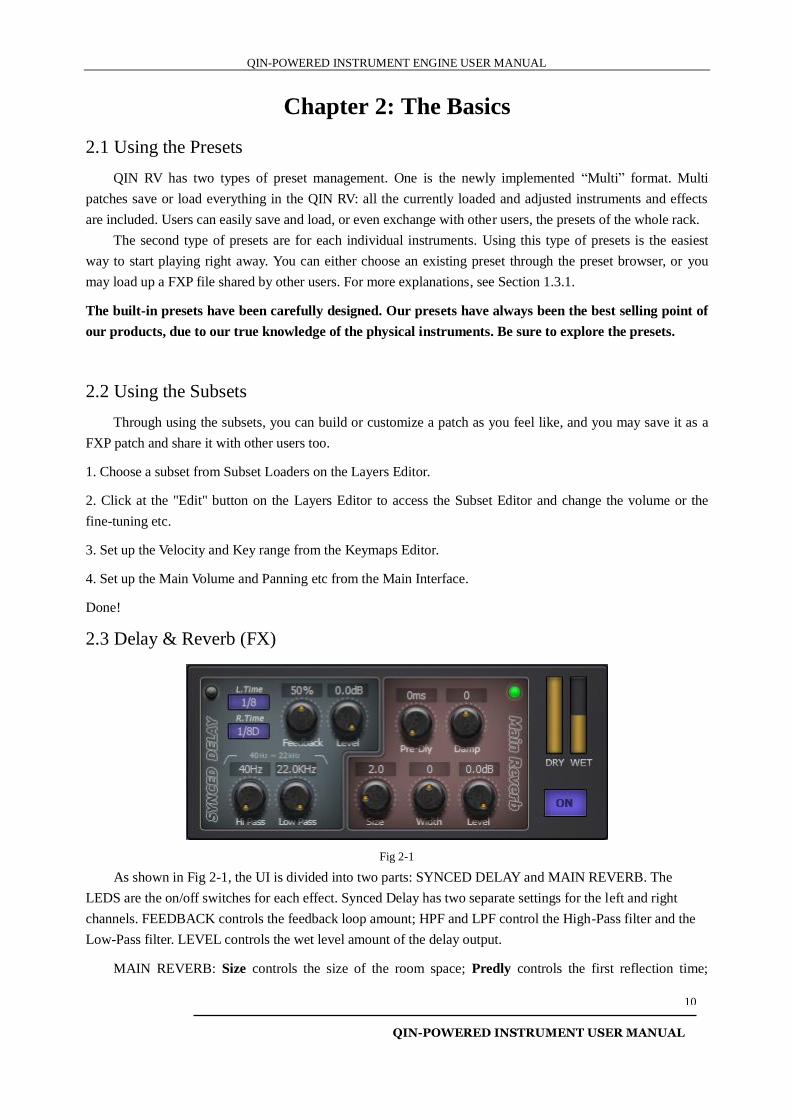
Use the Extenders Interface to load up and unload the Extenders (Ext). There are 10 Ext slots as shown
in Fig 1-11.
Fig 1-11
1) Loading an Extender:
Right click at an empty Ext slot and select an Ext from the pop-up menu. Once loaded, the empty
Ext slot will be represented by the Ext’s icon. The general Extenders’ editor can be opened by
clicking at the icons. Subset Extenders' editors have to be opened from within the Layers Editor’s
EDIT buttons.
NOTE: Almost all Extenders have an “ON” switch. It must be selected for the Extenders to be functional.
2) Unloading an Extender:
Right click at a loaded Ext slot and select “Unload” to unload the Ext. Once unloaded, the Ext
will no longer function for the selected patch.

QIN-POWERED INSTRUMENT ENGINE USER MANUAL
QIN-POWERED INSTRUMENT USER MANUAL
9
NOTE: The “Multi Channel” Ext will continue to function even after it is unloaded.
QIN-POWERED INSTRUMENT ENGINE USER MANUAL
QIN-POWERED INSTRUMENT USER MANUAL
10
Chapter 2: The Basics
2.1 Using the Presets
QIN RV has two types of preset management. One is the newly implemented “Multi” format. Multi
patches save or load everything in the QIN RV: all the currently loaded and adjusted instruments and effects
are included. Users can easily save and load, or even exchange with other users, the presets of the whole rack.
The second type of presets are for each individual instruments. Using this type of presets is the easiest
way to start playing right away. You can either choose an existing preset through the preset browser, or you
may load up a FXP file shared by other users. For more explanations, see Section 1.3.1.
The built-in presets have been carefully designed. Our presets have always been the best selling point of
our products, due to our true knowledge of the physical instruments. Be sure to explore the presets.
2.2 Using the Subsets
Through using the subsets, you can build or customize a patch as you feel like, and you may save it as a
FXP patch and share it with other users too.
1. Choose a subset from Subset Loaders on the Layers Editor.
2. Click at the "Edit" button on the Layers Editor to access the Subset Editor and change the volume or the
fine-tuning etc.
3. Set up the Velocity and Key range from the Keymaps Editor.
4. Set up the Main Volume and Panning etc from the Main Interface.
Done!
2.3 Delay & Reverb (FX)
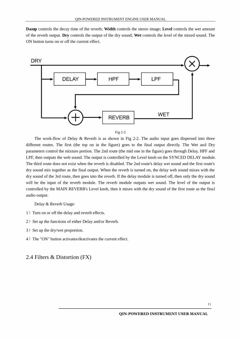
Fig 2-1
As shown in Fig 2-1, the UI is divided into two parts: SYNCED DELAY and MAIN REVERB. The
LEDS are the on/off switches for each effect. Synced Delay has two separate settings for the left and right
channels. FEEDBACK controls the feedback loop amount; HPF and LPF control the High-Pass filter and the
Low-Pass filter. LEVEL controls the wet level amount of the delay output.
MAIN REVERB: Size controls the size of the room space; Predly controls the first reflection time;
QIN-POWERED INSTRUMENT ENGINE USER MANUAL
QIN-POWERED INSTRUMENT USER MANUAL
11
Damp controls the decay time of the reverb; Width controls the stereo image; Level controls the wet amount
of the reverb output. Dry controls the output of the dry sound; Wet controls the level of the mixed sound. The
ON button turns on or off the current effect.
Fig 2-2
The work-flow of Delay & Reverb is as shown in Fig 2-2. The audio input goes dispersed into three
different routes. The first (the top on in the figure) goes to the final output directly. The Wet and Dry
parameters control the mixture portion. The 2nd route (the mid one in the figure) goes through Delay, HPF and
LPF, then outputs the web sound. The output is controlled by the Level knob on the SYNCED DELAY module.
The third route does not exist when the reverb is disabled. The 2nd route's delay wet sound and the first route's
dry sound mix together as the final output. When the reverb is turned on, the delay web sound mixes with the
dry sound of the 3rd route, then goes into the reverb. If the delay module is turned off, then only the dry sound
will be the input of the reverb module. The reverb module outputs wet sound. The level of the output is
controlled by the MAIN REVERB's Level knob, then it mixes with the dry sound of the first route as the final
audio output.
Delay & Reverb Usage:
1)Turn on or off the delay and reverb effects.
2)Set up the functions of either Delay and/or Reverb.
3)Set up the dry/wet proportion.
4)The "ON" button activates/deactivates the current effect.
2.4 Filters & Distortion (FX)
QIN-POWERED INSTRUMENT ENGINE USER MANUAL
QIN-POWERED INSTRUMENT USER MANUAL
12
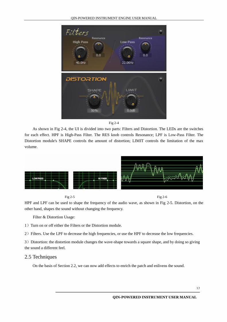
Fig 2-4
As shown in Fig 2-4, the UI is divided into two parts: Filters and Distortion. The LEDs are the switches
for each effect. HPF is High-Pass Filter. The RES knob controls Resonance; LPF is Low-Pass Filter. The
Distortion module's SHAPE controls the amount of distortion; LIMIT controls the limitation of the max
volume.
Fig 2-5 Fig 2-6
HPF and LPF can be used to shape the frequency of the audio wave, as shown in Fig 2-5. Distortion, on the
other hand, shapes the sound without changing the frequency.
Filter & Distortion Usage:
1)Turn on or off either the Filters or the Distortion module.
2)Filters. Use the LPF to decrease the high frequencies, or use the HPF to decrease the low frequencies.
3)Distortion: the distortion module changes the wave-shape towards a square shape, and by doing so giving
the sound a different feel.
2.5 Techniques
On the basis of Section 2.2, we can now add effects to enrich the patch and enlivens the sound.
QIN-POWERED INSTRUMENT ENGINE USER MANUAL
QIN-POWERED INSTRUMENT USER MANUAL
13
Chapter Three: The Extenders
There are two types of Extenders: the General Extenders which control (e.g., KeySwitch) all 12 subsets
(loaded through the Layers Editor) and the Subset Extenders that control (e.g. “the Pitch Envelope Extender")
each subset loaded into the Layers Editor.
3.1 General Extenders
The General Extenders are mostly for the sound-weaving/performance arrangement type of functions, in
order to make the sound alive. The effect Extenders can enrich the audio.
Loading an Extender: On the "EXTENDERS" User Interface, right-click at any empty Extender slot to
call up the selection menu. Once an Extender is loaded, left-click at the loaded Extender icon to bring up the
Extender editor where the settings of the Extender can be adjusted. Press the "OK" button at the bottom right
corner to exit the current Extender editor.
Unloading an Extender: right-click at the loaded Extender Icon and select "Unload" to unload the
Extender. Once unloaded, the Extender's functions stop functioning.
3.1.1 KeySwitch
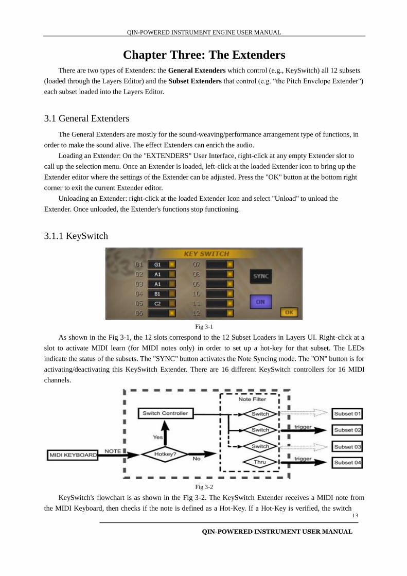
Fig 3-1
As shown in the Fig 3-1, the 12 slots correspond to the 12 Subset Loaders in Layers UI. Right-click at a
slot to activate MIDI learn (for MIDI notes only) in order to set up a hot-key for that subset. The LEDs
indicate the status of the subsets. The "SYNC" button activates the Note Syncing mode. The "ON" button is for
activating/deactivating this KeySwitch Extender. There are 16 different KeySwitch controllers for 16 MIDI
channels.
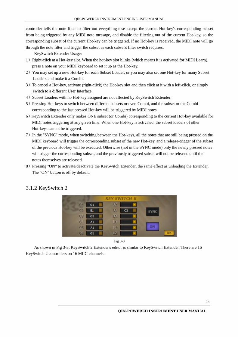
Fig 3-2
KeySwitch's flowchart is as shown in the Fig 3-2. The KeySwitch Extender receives a MIDI note from
the MIDI Keyboard, then checks if the note is defined as a Hot-Key. If a Hot-Key is verified, the switch
QIN-POWERED INSTRUMENT ENGINE USER MANUAL
QIN-POWERED INSTRUMENT USER MANUAL
14
controller tells the note filter to filter out everything else except the current Hot-key's corresponding subset
from being triggered by any MIDI note message, and disable the filtering out of the current Hot-key, so the
corresponding subset of the current Hot-key can be triggered. If no Hot-key is received, the MIDI note will go
through the note filter and trigger the subset as each subset's filter switch requires.
KeySwitch Extender Usage:
1)Right-click at a Hot-key slot. When the hot-key slot blinks (which means it is activated for MIDI Learn),
press a note on your MIDI keyboard to set it up as the Hot-key.
2)You may set up a new Hot-key for each Subset Loader; or you may also set one Hot-key for many Subset
Loaders and make it a Combi.
3)To cancel a Hot-key, activate (right-click) the Hot-key slot and then click at it with a left-click, or simply
switch to a different User Interface.
4)Subset Loaders with no Hot-key assigned are not affected by KeySwitch Extender;
5)Pressing Hot-keys to switch between different subsets or even Combi, and the subset or the Combi
corresponding to the last pressed Hot-key will be triggered by MIDI notes.
6)KeySwitch Extender only makes ONE subset (or Combi) corresponding to the current Hot-key available for
MIDI notes triggering at any given time. When one Hot-key is activated, the subset loaders of other
Hot-keys cannot be triggered.
7)In the "SYNC" mode, when switching between the Hot-keys, all the notes that are still being pressed on the
MIDI keyboard will trigger the corresponding subset of the new Hot-key, and a release-trigger of the subset
of the previous Hot-key will be executed. Otherwise (not in the SYNC mode) only the newly pressed notes
will trigger the corresponding subset, and the previously triggered subset will not be released until the
notes themselves are released.
8)Pressing "ON" to activate/deactivate the KeySwitch Extender, the same effect as unloading the Extender.
The "ON" button is off by default.
3.1.2 KeySwitch 2
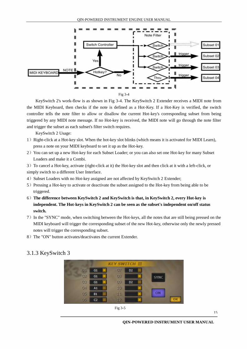
Fig 3-3
As shown in Fig 3-3, KeySwitch 2 Extender's editor is similar to KeySwitch Extender. There are 16
KeySwitch 2 controllers on 16 MIDI channels.
QIN-POWERED INSTRUMENT ENGINE USER MANUAL
QIN-POWERED INSTRUMENT USER MANUAL
15
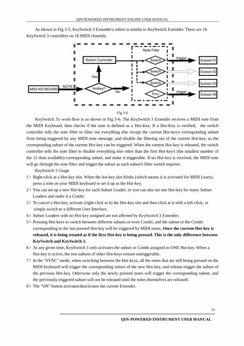
Fig 3-4
KeySwitch 2's work-flow is as shown in Fig 3-4. The KeySwitch 2 Extender receives a MIDI note from
the MIDI Keyboard, then checks if the note is defined as a Hot-Key. If a Hot-Key is verified, the switch
controller tells the note filter to allow or disallow the current Hot-key's corresponding subset from being
triggered by any MIDI note message. If no Hot-key is received, the MIDI note will go through the note filter
and trigger the subset as each subset's filter switch requires.
KeySwitch 2 Usage:
1)Right-click at a Hot-key slot. When the hot-key slot blinks (which means it is activated for MIDI Learn),
press a note on your MIDI keyboard to set it up as the Hot-key.
2)You can set up a new Hot-key for each Subset Loader; or you can also set one Hot-key for many Subset
Loaders and make it a Combi.
3)To cancel a Hot-key, activate (right-click at it) the Hot-key slot and then click at it with a left-click, or
simply switch to a different User Interface.
4)Subset Loaders with no Hot-key assigned are not affected by KeySwitch 2 Extender;
5)Pressing a Hot-key to activate or deactivate the subset assigned to the Hot-key from being able to be
triggered.
6)The difference between KeySwitch 2 and KeySwitch is that, in KeySwitch 2, every Hot-key is
independent. The Hot-keys in KeySwitch 2 can be seen as the subset's independent on/off status
switch.
7)In the "SYNC" mode, when switching between the Hot-keys, all the notes that are still being pressed on the
MIDI keyboard will trigger the corresponding subset of the new Hot-key, otherwise only the newly pressed
notes will trigger the corresponding subset.
8)The "ON" button activates/deactivates the current Extender.
3.1.3 KeySwitch 3
Fig 3-5
QIN-POWERED INSTRUMENT ENGINE USER MANUAL
QIN-POWERED INSTRUMENT USER MANUAL
16
As shown in Fig 3-5, KeySwitch 3 Extender's editor is similar to KeySwitch Extender. There are 16
KeySwitch 3 controllers on 16 MIDI channels.
Fig 3-6
KeySwitch 3's work-flow is as shown in Fig 3-6. The KeySwitch 3 Extender receives a MIDI note from
the MIDI Keyboard, then checks if the note is defined as a Hot-Key. If a Hot-Key is verified, the switch
controller tells the note filter to filter out everything else except the current Hot-key's corresponding subset
from being triggered by any MIDI note message, and disable the filtering out of the current Hot-key, so the
corresponding subset of the current Hot-key can be triggered. When the current Hot-key is released, the switch
controller tells the note filter to disable everything else other than the first Hot-key's (the smallest number of
the 12 slots available) corresponding subset, and make it triggerable. If no Hot-key is received, the MIDI note
will go through the note filter and trigger the subset as each subset's filter switch requires.
KeySwitch 3 Usage
1)Right-click at a Hot-key slot. When the hot-key slot blinks (which means it is activated for MIDI Learn),
press a note on your MIDI keyboard to set it up as the Hot-key.
2)You can set up a new Hot-key for each Subset Loader; or you can also set one Hot-key for many Subset
Loaders and make it a Combi.
3)To cancel a Hot-key, activate (right-click at it) the Hot-key slot and then click at it with a left-click, or
simply switch to a different User Interface.
4)Subset Loaders with no Hot-key assigned are not affected by KeySwitch 3 Extender;
5)Pressing Hot-keys to switch between different subsets or even Combi, and the subset or the Combi
corresponding to the last pressed Hot-key will be triggered by MIDI notes. Once the current Hot-key is
released, it is being treated as if the first Hot-key is being pressed. This is the only difference between
KeySwitch and KeySwitch 3.
6)At any given time, KeySwitch 3 only activates the subset or Combi assigned to ONE Hot-key. When a
Hot-key is active, the rest subsets of other Hot-keys remain untriggerable.
7)In the "SYNC" mode, when switching between the Hot-keys, all the notes that are still being pressed on the
MIDI keyboard will trigger the corresponding subset of the new Hot-key, and release-trigger the subset of
the previous Hot-key. Otherwise only the newly pressed notes will trigger the corresponding subset, and
the previously triggered subset will not be released until the notes themselves are released.
8)The "ON" button activates/deactivates the current Extender.
QIN-POWERED INSTRUMENT ENGINE USER MANUAL
QIN-POWERED INSTRUMENT USER MANUAL
17
3.1.4 Program Change
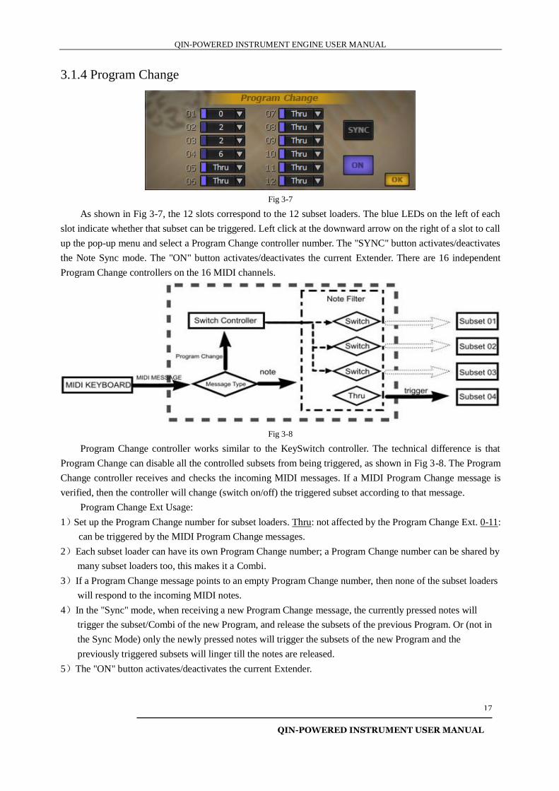
Fig 3-7
As shown in Fig 3-7, the 12 slots correspond to the 12 subset loaders. The blue LEDs on the left of each
slot indicate whether that subset can be triggered. Left click at the downward arrow on the right of a slot to call
up the pop-up menu and select a Program Change controller number. The "SYNC" button activates/deactivates
the Note Sync mode. The "ON" button activates/deactivates the current Extender. There are 16 independent
Program Change controllers on the 16 MIDI channels.
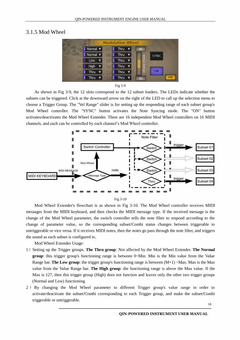
Fig 3-8
Program Change controller works similar to the KeySwitch controller. The technical difference is that
Program Change can disable all the controlled subsets from being triggered, as shown in Fig 3-8. The Program
Change controller receives and checks the incoming MIDI messages. If a MIDI Program Change message is
verified, then the controller will change (switch on/off) the triggered subset according to that message.
Program Change Ext Usage:
1)Set up the Program Change number for subset loaders. Thru: not affected by the Program Change Ext. 0-11:
can be triggered by the MIDI Program Change messages.
2)Each subset loader can have its own Program Change number; a Program Change number can be shared by
many subset loaders too, this makes it a Combi.
3)If a Program Change message points to an empty Program Change number, then none of the subset loaders
will respond to the incoming MIDI notes.
4)In the "Sync" mode, when receiving a new Program Change message, the currently pressed notes will
trigger the subset/Combi of the new Program, and release the subsets of the previous Program. Or (not in
the Sync Mode) only the newly pressed notes will trigger the subsets of the new Program and the
previously triggered subsets will linger till the notes are released.
5)The "ON" button activates/deactivates the current Extender.
QIN-POWERED INSTRUMENT ENGINE USER MANUAL
QIN-POWERED INSTRUMENT USER MANUAL
18
3.1.5 Mod Wheel
Fig 3-9
As shown in Fig 3-9, the 12 slots correspond to the 12 subset loaders. The LEDs indicate whether the
subsets can be triggered. Click at the downward arrow on the right of the LED to call up the selection menu to
choose a Trigger Group. The "Vel Range" slider is for setting up the responding range of each subset group's
Mod Wheel controller. The "SYNC" button activates the Note Syncing mode. The "ON" button
activates/deactivates the Mod Wheel Extender. There are 16 independent Mod Wheel controllers on 16 MIDI
channels, and each can be controlled by each channel’s Mod Wheel controller.
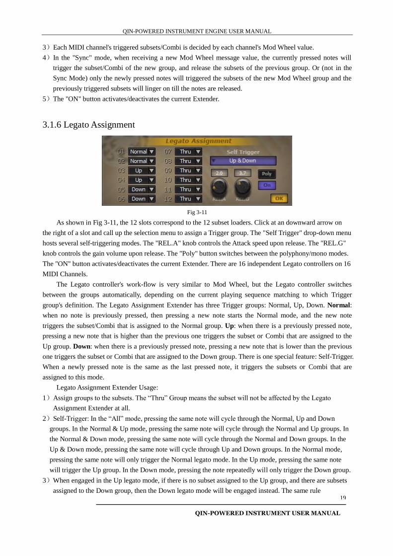
Fig 3-10
Mod Wheel Extender's flowchart is as shown in Fig 3-10. The Mod Wheel controller receives MIDI
messages from the MIDI keyboard, and then checks the MIDI message type. If the received message is the
change of the Mod Wheel parameter, the switch controller tells the note filter to respond according to the
change of parameter value, so the corresponding subset/Combi status changes between triggerable to
untriggerable or vice versa. If it receives MIDI notes, then the notes go pass through the note filter, and triggers
the sound as each subset is configured to.
Mod Wheel Extender Usage:
1)Setting up the Trigger groups. The Thru group: Not affected by the Mod Wheel Extender. The Normal
group: this trigger group's functioning range is between 0~Min. Min is the Min value from the Value
Range bar. The Low group: the trigger group's functioning range is between (M+1) ~Max. Max is the Max
value from the Value Range bar. The High group: the functioning range is above the Max value. If the
Max is 127, then this trigger group (High) does not function and leaves only the other two trigger groups
(Normal and Low) functioning.
2 ) By changing the Mod Wheel parameter to different Trigger group's value range in order to
activate/deactivate the subset/Combi corresponding to each Trigger group, and make the subset/Combi
triggerable or untriggerable.
QIN-POWERED INSTRUMENT ENGINE USER MANUAL
QIN-POWERED INSTRUMENT USER MANUAL
19
3)Each MIDI channel's triggered subsets/Combi is decided by each channel's Mod Wheel value.
4)In the "Sync" mode, when receiving a new Mod Wheel message value, the currently pressed notes will
trigger the subset/Combi of the new group, and release the subsets of the previous group. Or (not in the
Sync Mode) only the newly pressed notes will triggered the subsets of the new Mod Wheel group and the
previously triggered subsets will linger on till the notes are released.
5)The "ON" button activates/deactivates the current Extender.
3.1.6 Legato Assignment
Fig 3-11
As shown in Fig 3-11, the 12 slots correspond to the 12 subset loaders. Click at an downward arrow on
the right of a slot and call up the selection menu to assign a Trigger group. The "Self Trigger" drop-down menu
hosts several self-triggering modes. The "REL.A" knob controls the Attack speed upon release. The "REL.G"
knob controls the gain volume upon release. The "Poly" button switches between the polyphony/mono modes.
The "ON" button activates/deactivates the current Extender. There are 16 independent Legato controllers on 16
MIDI Channels.
The Legato controller's work-flow is very similar to Mod Wheel, but the Legato controller switches
between the groups automatically, depending on the current playing sequence matching to which Trigger
group's definition. The Legato Assignment Extender has three Trigger groups: Normal, Up, Down. Normal:
when no note is previously pressed, then pressing a new note starts the Normal mode, and the new note
triggers the subset/Combi that is assigned to the Normal group. Up: when there is a previously pressed note,
pressing a new note that is higher than the previous one triggers the subset or Combi that are assigned to the
Up group. Down: when there is a previously pressed note, pressing a new note that is lower than the previous
one triggers the subset or Combi that are assigned to the Down group. There is one special feature: Self-Trigger.
When a newly pressed note is the same as the last pressed note, it triggers the subsets or Combi that are
assigned to this mode.
Legato Assignment Extender Usage:
1)Assign groups to the subsets. The “Thru” Group means the subset will not be affected by the Legato
Assignment Extender at all.
2)Self-Trigger: In the “All” mode, pressing the same note will cycle through the Normal, Up and Down
groups. In the Normal & Up mode, pressing the same note will cycle through the Normal and Up groups. In
the Normal & Down mode, pressing the same note will cycle through the Normal and Down groups. In the
Up & Down mode, pressing the same note will cycle through Up and Down groups. In the Normal mode,
pressing the same note will only trigger the Normal legato mode. In the Up mode, pressing the same note
will trigger the Up group. In the Down mode, pressing the note repeatedly will only trigger the Down group.
3)When engaged in the Up legato mode, if there is no subset assigned to the Up group, and there are subsets
assigned to the Down group, then the Down legato mode will be engaged instead. The same rule
QIN-POWERED INSTRUMENT ENGINE USER MANUAL
QIN-POWERED INSTRUMENT USER MANUAL
20
applies when engaged in the Down legato mode with no subsets assigned to it, then the Up legato mode
will be engaged instead. If the both Up and Down legato groups are not assigned, then the Normal mode
will be engaged.
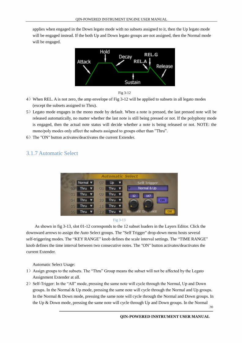
Fig 3-12
4)When REL. A is not zero, the amp envelope of Fig 3-12 will be applied to subsets in all legato modes
(except the subsets assigned to Thru).
5)Legato mode engages in the mono mode by default. When a note is pressed, the last pressed note will be
released automatically, no matter whether the last note is still being pressed or not. If the polyphony mode
is engaged, then the actual note status will decide whether a note is being released or not. NOTE: the
mono/poly modes only affect the subsets assigned to groups other than ”Thru”.
6)The "ON" button activates/deactivates the current Extender.
3.1.7 Automatic Select
Fig 3-13
As shown in fig 3-13, slot 01-12 corresponds to the 12 subset loaders in the Layers Editor. Click the
downward arrows to assign the Auto Select groups. The "Self Trigger" drop-down menu hosts several
self-triggering modes. The “KEY RANGE” knob defines the scale interval settings. The “TIME RANGE”
knob defines the time interval between two consecutive notes. The "ON" button activates/deactivates the
current Extender.
Automatic Select Usage:
1)Assign groups to the subsets. The “Thru” Group means the subset will not be affected by the Legato
Assignment Extender at all.
2)Self-Trigger: In the “All” mode, pressing the same note will cycle through the Normal, Up and Down
groups. In the Normal & Up mode, pressing the same note will cycle through the Normal and Up groups.
In the Normal & Down mode, pressing the same note will cycle through the Normal and Down groups. In
the Up & Down mode, pressing the same note will cycle through Up and Down groups. In the Normal
QIN-POWERED INSTRUMENT ENGINE USER MANUAL
QIN-POWERED INSTRUMENT USER MANUAL
21
mode, pressing the same note will only trigger the Normal legato mode. In the Up mode, pressing the same
note will trigger the Up group. In the Down mode, pressing the note repeatedly will only trigger the Down
group.
3)When the notes played are from lower notes to higher notes, if there is no subset assigned to the Up group,
and there are subsets assigned to the Down group, then the Down group will be engaged instead.
Conversely, the same rule applies when the notes are played from the higher notes to the lower notes and
there is no subset assigned to the Down group, and there are subsets assigned to the Up group, then the Up
group will be engaged instead. If the both Up and Down groups are not assigned, then the Normal group
will be engaged.
4)KEY RANGE(semitone)delimits the scale interval between two consecutively played notes. Only when the
semitone interval is within this KEY RANGE will the notes meet the requirement for triggering groups
other than “Normal”.
5)TIME RANGE (ms) delimits the time interval between two notes. Only when the time interval is within
this TIME RANGE will the notes meet the requirement for triggering groups other than “Normal”.
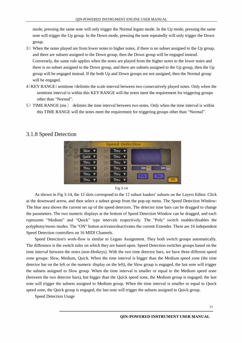
3.1.8 Speed Detection
Fig 3-14
As shown in Fig 3-14, the 12 slots correspond to the 12 subset loaders’ subsets on the Layers Editor. Click
at the downward arrow, and then select a subset group from the pop-up menu. The Speed Detection Window:
The blue area shows the current set up of the speed detectors. The detector time bars can be dragged to change
the parameters. The two numeric displays at the bottom of Speed Detection Window can be dragged, and each
represents “Medium” and “Quick” type intervals respectively. The "Poly" switch enables/disables the
polyphony/mono modes. The "ON" button activates/deactivates the current Extender. There are 16 independent
Speed Detection controllers on 16 MIDI Channels.
Speed Detection's work-flow is similar to Legato Assignment. They both switch groups automatically.
The difference is the switch rules on which they are based upon. Speed Detection switches groups based on the
time interval between the notes (non-Hotkeys). With the two time detector bars, we have three different speed
zone groups: Slow, Medium, Quick. When the time interval is bigger than the Medium speed zone (the time
detector bar on the left or the numeric display on the left), the Slow group is engaged, the last note will trigger
the subsets assigned to Slow group. When the time interval is smaller or equal to the Medium speed zone
(between the two detector bars), but bigger than the Quick speed zone, the Medium group is engaged; the last
note will trigger the subsets assigned to Medium group. When the time interval is smaller or equal to Quick
speed zone, the Quick group is engaged, the last note will trigger the subsets assigned to Quick group.
Speed Detection Usage
QIN-POWERED INSTRUMENT ENGINE USER MANUAL
QIN-POWERED INSTRUMENT USER MANUAL
22
1)Set up and assign subsets to different speed groups. The "Thru" group is not affected by Speed Detection
Extender.
2)When the two time detector bars share the same value, the Medium group is ignored (as the case in Fig
3-14).
3)In the mono mode, when a note is pressed, the last pressed note is automatically released The default mode
is poly mode. NOTE: poly/mono mode does not affect the subsets assigned to the "Thru" group.
4)The "ON" button activates/deactivates the current Extender.
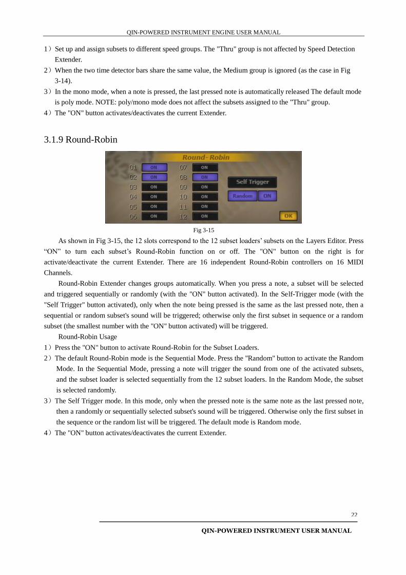
3.1.9 Round-Robin
Fig 3-15
As shown in Fig 3-15, the 12 slots correspond to the 12 subset loaders’ subsets on the Layers Editor. Press
“ON” to turn each subset’s Round-Robin function on or off. The "ON" button on the right is for
activate/deactivate the current Extender. There are 16 independent Round-Robin controllers on 16 MIDI
Channels.
Round-Robin Extender changes groups automatically. When you press a note, a subset will be selected
and triggered sequentially or randomly (with the "ON" button activated). In the Self-Trigger mode (with the
"Self Trigger" button activated), only when the note being pressed is the same as the last pressed note, then a
sequential or random subset's sound will be triggered; otherwise only the first subset in sequence or a random
subset (the smallest number with the "ON" button activated) will be triggered.
Round-Robin Usage
1)Press the "ON" button to activate Round-Robin for the Subset Loaders.
2)The default Round-Robin mode is the Sequential Mode. Press the "Random" button to activate the Random
Mode. In the Sequential Mode, pressing a note will trigger the sound from one of the activated subsets,
and the subset loader is selected sequentially from the 12 subset loaders. In the Random Mode, the subset
is selected randomly.
3)The Self Trigger mode. In this mode, only when the pressed note is the same note as the last pressed note,
then a randomly or sequentially selected subset's sound will be triggered. Otherwise only the first subset in
the sequence or the random list will be triggered. The default mode is Random mode.
4)The "ON" button activates/deactivates the current Extender.
QIN-POWERED INSTRUMENT ENGINE USER MANUAL
QIN-POWERED INSTRUMENT USER MANUAL
23
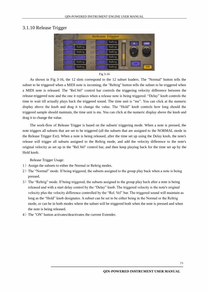
3.1.10 Release Trigger
Fig 3-16
As shown in Fig 3-16, the 12 slots correspond to the 12 subset loaders. The "Normal" button tells the
subset to be triggered when a MIDI note is incoming; the "Reltrig" button tells the subset to be triggered when
a MIDI note is released. The "Rel.Vel" control bar controls the triggering velocity difference between the
release-triggered note and the one it replaces when a release note is being triggered. “Delay” knob controls the
time to wait till actually plays back the triggered sound. The time unit is “ms”. You can click at the numeric
display above the knob and drag it to change the value. The “Hold” knob controls how long should the
triggered sample should maintain, the time unit is ms. You can click at the numeric display above the knob and
drag it to change the value.
The work-flow of Release Trigger is based on the subsets' triggering mode. When a note is pressed, the
note triggers all subsets that are set to be triggered (all the subsets that are assigned to the NORMAL mode in
the Release Trigger Ext). When a note is being released, after the time set up using the Delay knob, the note's
release will trigger all subsets assigned to the Reltrig mode, and add the velocity difference to the note's
original velocity as set up in the "Rel.Vel" control bar, and then keep playing back for the time set up by the
Hold knob.
Release Trigger Usage:
1)Assign the subsets to either the Normal or Reltrig modes.
2)The “Normal” mode. If being triggered, the subsets assigned to the group play back when a note is being
pressed.
3)The “Reltrig” mode. If being triggered, the subsets assigned to the group play back after a note is being
released and with a start delay control by the “Delay” knob. The triggered velocity is the note's original
velocity plus the velocity difference controlled by the “Rel. Vel” bar. The triggered sound will maintain as
long as the “Hold” knob designates. A subset can be set to be either being in the Normal or the Reltrig
mode, or can be in both modes where the subset will be triggered both when the note is pressed and when
the note is being released.
4)The "ON" button activates/deactivates the current Extender.
QIN-POWERED INSTRUMENT ENGINE USER MANUAL
QIN-POWERED INSTRUMENT USER MANUAL
24
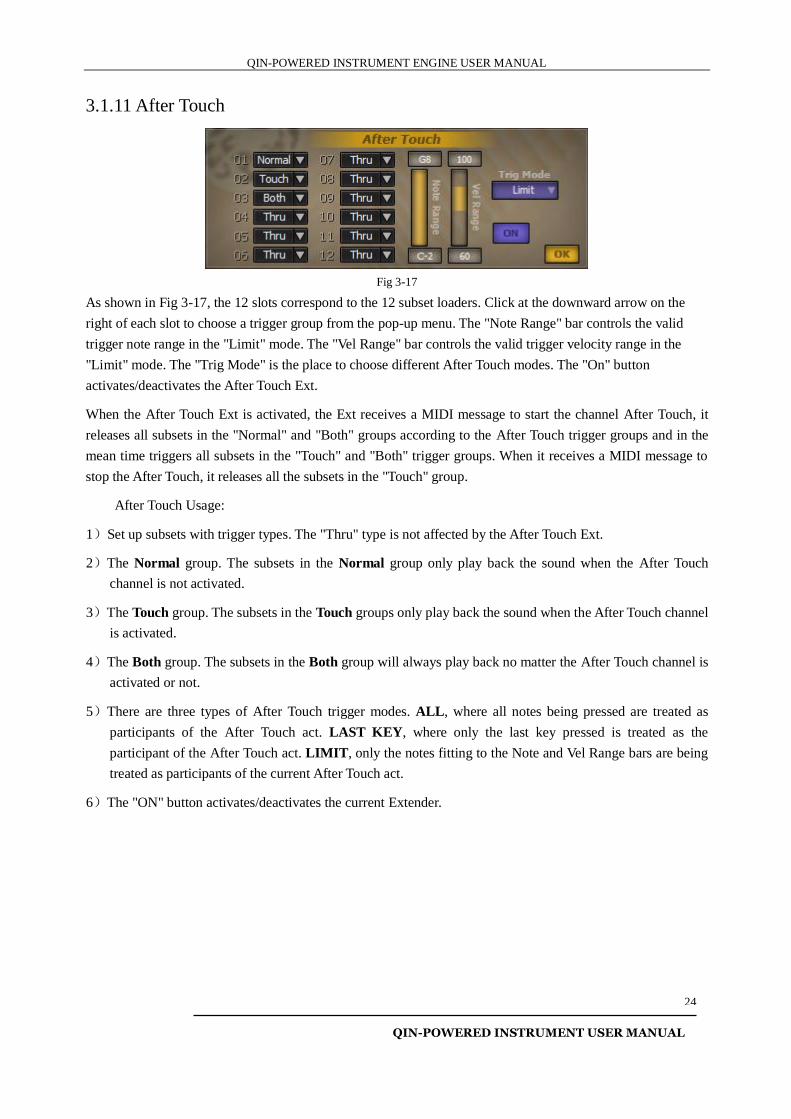
3.1.11 After Touch
Fig 3-17
As shown in Fig 3-17, the 12 slots correspond to the 12 subset loaders. Click at the downward arrow on the
right of each slot to choose a trigger group from the pop-up menu. The "Note Range" bar controls the valid
trigger note range in the "Limit" mode. The "Vel Range" bar controls the valid trigger velocity range in the
"Limit" mode. The "Trig Mode" is the place to choose different After Touch modes. The "On" button
activates/deactivates the After Touch Ext.
When the After Touch Ext is activated, the Ext receives a MIDI message to start the channel After Touch, it
releases all subsets in the "Normal" and "Both" groups according to the After Touch trigger groups and in the
mean time triggers all subsets in the "Touch" and "Both" trigger groups. When it receives a MIDI message to
stop the After Touch, it releases all the subsets in the "Touch" group.
After Touch Usage:
1)Set up subsets with trigger types. The "Thru" type is not affected by the After Touch Ext.
2)The Normal group. The subsets in the Normal group only play back the sound when the After Touch
channel is not activated.
3)The Touch group. The subsets in the Touch groups only play back the sound when the After Touch channel
is activated.
4)The Both group. The subsets in the Both group will always play back no matter the After Touch channel is
activated or not.
5)There are three types of After Touch trigger modes. ALL, where all notes being pressed are treated as
participants of the After Touch act. LAST KEY, where only the last key pressed is treated as the
participant of the After Touch act. LIMIT, only the notes fitting to the Note and Vel Range bars are being
treated as participants of the current After Touch act.
6)The "ON" button activates/deactivates the current Extender.
QIN-POWERED INSTRUMENT ENGINE USER MANUAL
QIN-POWERED INSTRUMENT USER MANUAL
25
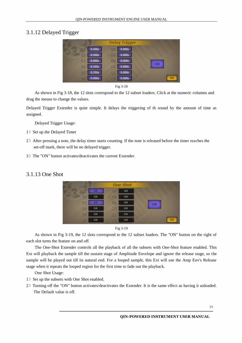
3.1.12 Delayed Trigger
Fig 3-18
As shown in Fig 3-18, the 12 slots correspond to the 12 subset loaders. Click at the numeric columns and
drag the mouse to change the values.
Delayed Trigger Extender is quite simple. It delays the triggering of th sound by the amount of time as
assigned.
Delayed Trigger Usage:
1)Set up the Delayed Timer
2)After pressing a note, the delay timer starts counting. If the note is released before the timer reaches the
set-off mark, there will be no delayed trigger.
3)The "ON" button activates/deactivates the current Extender.
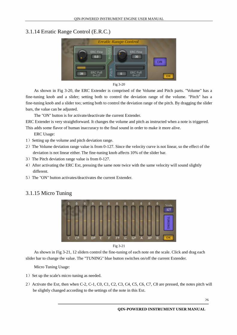
3.1.13 One Shot
Fig 3-19
As shown in Fig 3-19, the 12 slots correspond to the 12 subset loaders. The "ON" button on the right of
each slot turns the feature on and off.
The One-Shot Extender controls all the playback of all the subsets with One-Shot feature enabled. This
Ext will playback the sample till the sustain stage of Amplitude Envelope and ignore the release stage, so the
sample will be played out till its natural end. For a looped sample, this Ext will use the Amp Env's Release
stage when it repeats the looped region for the first time to fade out the playback.
One Shot Usage:
1)Set up the subsets with One Shot enabled.
2)Turning off the "ON" button activates/deactivates the Extender. It is the same effect as having it unloaded.
The Default value is off.
QIN-POWERED INSTRUMENT ENGINE USER MANUAL
QIN-POWERED INSTRUMENT USER MANUAL
26
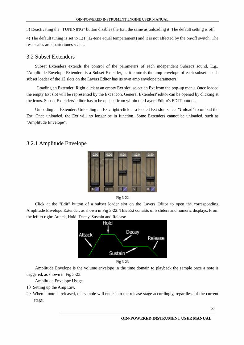
3.1.14 Erratic Range Control (E.R.C.)
Fig 3-20
As shown in Fig 3-20, the ERC Extender is comprised of the Volume and Pitch parts. "Volume" has a
fine-tuning knob and a slider; setting both to control the deviation range of the volume. "Pitch" has a
fine-tuning knob and a slider too; setting both to control the deviation range of the pitch. By dragging the slider
bars, the value can be adjusted.
The "ON" button is for activate/deactivate the current Extender.
ERC Extender is very straightforward. It changes the volume and pitch as instructed when a note is triggered.
This adds some flavor of human inaccuracy to the final sound in order to make it more alive.
ERC Usage:
1)Setting up the volume and pitch deviation range.
2)The Volume deviation range value is from 0-127. Since the velocity curve is not linear, so the effect of the
deviation is not linear either. The fine-tuning knob affects 10% of the slider bar.
3)The Pitch deviation range value is from 0-127.
4)After activating the ERC Ext, pressing the same note twice with the same velocity will sound slightly
different.
5)The "ON" button activates/deactivates the current Extender.
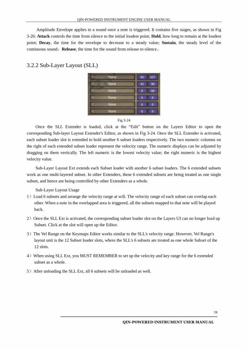
3.1.15 Micro Tuning
Fig 3-21
As shown in Fig 3-21, 12 sliders control the fine-tuning of each note on the scale. Click and drag each
slider bar to change the value. The "TUNING" blue button switches on/off the current Extender.
Micro Tuning Usage:
1)Set up the scale's micro tuning as needed.
2)Activate the Ext, then when C-2, C-1, C0, C1, C2, C3, C4, C5, C6, C7, C8 are pressed, the notes pitch will
be slightly changed according to the settings of the note in this Ext.
QIN-POWERED INSTRUMENT ENGINE USER MANUAL
QIN-POWERED INSTRUMENT USER MANUAL
27
3) Deactivating the "TUNINING" button disables the Ext, the same as unloading it. The default setting is off.
4) The default tuning is set to 12T.(12-tone equal temperament) and it is not affected by the on/off switch. The
rest scales are quartertones scales.
3.2 Subset Extenders
Subset Extenders extends the control of the parameters of each independent Subset's sound. E.g.,
"Amplitude Envelope Extender" is a Subset Extender, as it controls the amp envelope of each subset - each
subset loader of the 12 slots on the Layers Editor has its own amp envelope parameters.
Loading an Extender: Right click at an empty Ext slot, select an Ext from the pop-up menu. Once loaded,
the empty Ext slot will be represented by the Ext's icon. General Extenders' editor can be opened by clicking at
the icons. Subset Extenders' editor has to be opened from within the Layers Editor's EDIT buttons.
Unloading an Extender: Unloading an Ext: right-click at a loaded Ext slot, select "Unload" to unload the
Ext. Once unloaded, the Ext will no longer be in function. Some Extenders cannot be unloaded, such as
"Amplitude Envelope".
3.2.1 Amplitude Envelope
Fig 3-22
Click at the "Edit" button of a subset loader slot on the Layers Editor to open the corresponding
Amplitude Envelope Extender, as shown in Fig 3-22. This Ext consists of 5 sliders and numeric displays. From
the left to right: Attack, Hold, Decay, Sustain and Release.
Fig 3-23
Amplitude Envelope is the volume envelope in the time domain to playback the sample once a note is
triggered, as shown in Fig 3-23.
Amplitude Envelope Usage.
1)Setting up the Amp Env.
2)When a note is released, the sample will enter into the release stage accordingly, regardless of the current
stage.
QIN-POWERED INSTRUMENT ENGINE USER MANUAL
QIN-POWERED INSTRUMENT USER MANUAL
28
Amplitude Envelope applies to a sound once a note is triggered. It contains five stages, as shown in Fig
3-26: Attack controls the time from silence to the initial loudest point; Hold, how long to remain at the loudest
point; Decay, the time for the envelope to decrease to a steady value; Sustain, the steady level of the
continuous sound;Release, the time for the sound from release to silence。
3.2.2 Sub-Layer Layout (SLL)
Fig 3-24
Once the SLL Extender is loaded, click at the “Edit” button on the Layers Editor to open the
corresponding Sub-layer Layout Extender's Editor, as shown in Fig 3-24. Once the SLL Extender is activated,
each subset loader slot is extended to hold another 6 subset loaders respectively. The two numeric columns on
the right of each extended subset loader represent the velocity range. The numeric displays can be adjusted by
dragging on them vertically. The left numeric is the lowest velocity value; the right numeric is the highest
velocity value.
Sub-Layer Layout Ext extends each Subset loader with another 6 subset loaders. The 6 extended subsets
work as one multi-layered subset. In other Extenders, these 6 extended subsets are being treated as one single
subset, and hence are being controlled by other Extenders as a whole.
Sub-Layer Layout Usage
1)Load 6 subsets and arrange the velocity range at will. The velocity range of each subset can overlap each
other. When a note in the overlapped area is triggered, all the subsets mapped to that note will be played
back.
2)Once the SLL Ext is activated, the corresponding subset loader slot on the Layers UI can no longer load up
Subset. Click at the slot will open up the Editor.
3)The Vel Range on the Keymaps Editor works similar to the SLL's velocity range. However, Vel Range's
layout unit is the 12 Subset loader slots, where the SLL's 6 subsets are treated as one whole Subset of the
12 slots.
4)When using SLL Ext, you MUST REMEMBER to set up the velocity and key range for the 6 extended
subset as a whole.
5)After unloading the SLL Ext, all 6 subsets will be unloaded as well.
QIN-POWERED INSTRUMENT ENGINE USER MANUAL
QIN-POWERED INSTRUMENT USER MANUAL
29
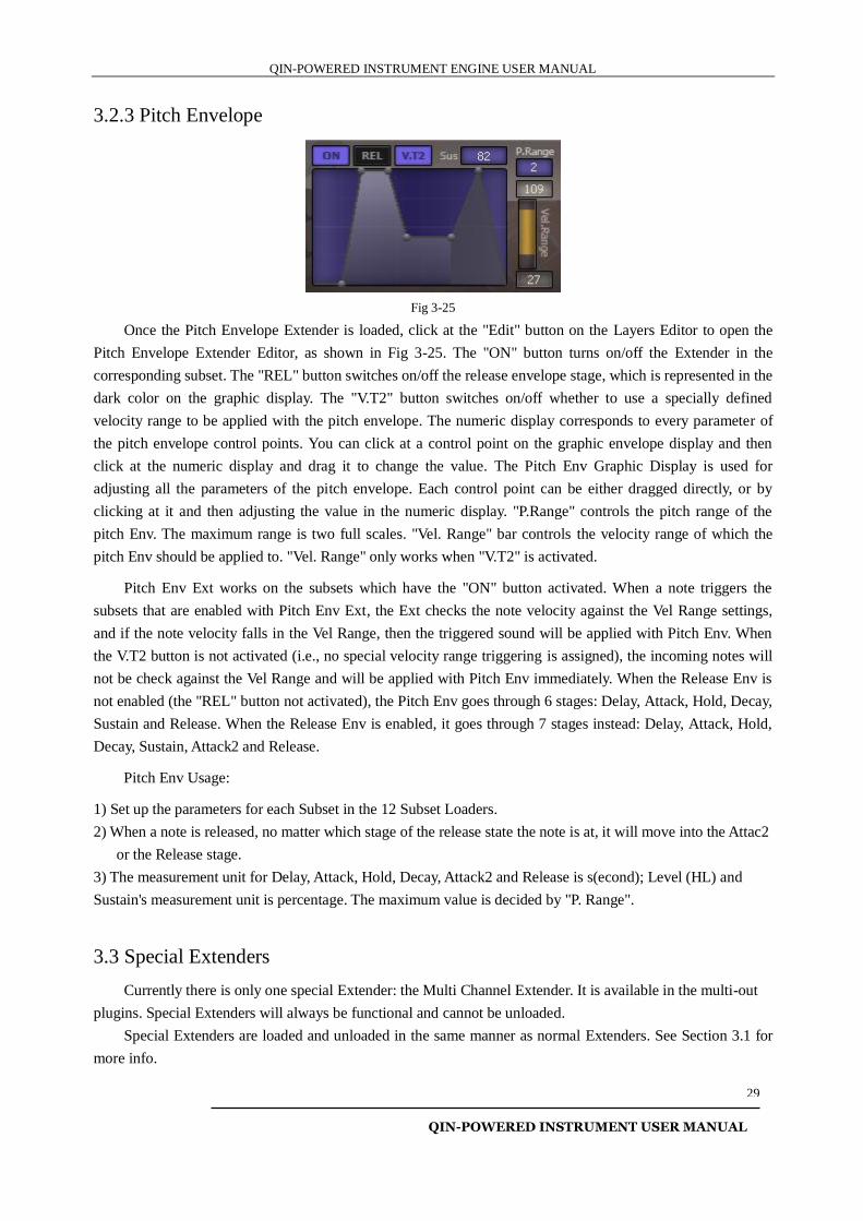
3.2.3 Pitch Envelope
Fig 3-25
Once the Pitch Envelope Extender is loaded, click at the "Edit" button on the Layers Editor to open the
Pitch Envelope Extender Editor, as shown in Fig 3-25. The "ON" button turns on/off the Extender in the
corresponding subset. The "REL" button switches on/off the release envelope stage, which is represented in the
dark color on the graphic display. The "V.T2" button switches on/off whether to use a specially defined
velocity range to be applied with the pitch envelope. The numeric display corresponds to every parameter of
the pitch envelope control points. You can click at a control point on the graphic envelope display and then
click at the numeric display and drag it to change the value. The Pitch Env Graphic Display is used for
adjusting all the parameters of the pitch envelope. Each control point can be either dragged directly, or by
clicking at it and then adjusting the value in the numeric display. "P.Range" controls the pitch range of the
pitch Env. The maximum range is two full scales. "Vel. Range" bar controls the velocity range of which the
pitch Env should be applied to. "Vel. Range" only works when "V.T2" is activated.
Pitch Env Ext works on the subsets which have the "ON" button activated. When a note triggers the
subsets that are enabled with Pitch Env Ext, the Ext checks the note velocity against the Vel Range settings,
and if the note velocity falls in the Vel Range, then the triggered sound will be applied with Pitch Env. When
the V.T2 button is not activated (i.e., no special velocity range triggering is assigned), the incoming notes will
not be check against the Vel Range and will be applied with Pitch Env immediately. When the Release Env is
not enabled (the "REL" button not activated), the Pitch Env goes through 6 stages: Delay, Attack, Hold, Decay,
Sustain and Release. When the Release Env is enabled, it goes through 7 stages instead: Delay, Attack, Hold,
Decay, Sustain, Attack2 and Release.
Pitch Env Usage:
1) Set up the parameters for each Subset in the 12 Subset Loaders.
2) When a note is released, no matter which stage of the release state the note is at, it will move into the Attac2
or the Release stage.
3) The measurement unit for Delay, Attack, Hold, Decay, Attack2 and Release is s(econd); Level (HL) and
Sustain's measurement unit is percentage. The maximum value is decided by "P. Range".
3.3 Special Extenders
Currently there is only one special Extender: the Multi Channel Extender. It is available in the multi-out
plugins. Special Extenders will always be functional and cannot be unloaded.
Special Extenders are loaded and unloaded in the same manner as normal Extenders. See Section 3.1 for
more info.
QIN-POWERED INSTRUMENT ENGINE USER MANUAL
QIN-POWERED INSTRUMENT USER MANUAL
30
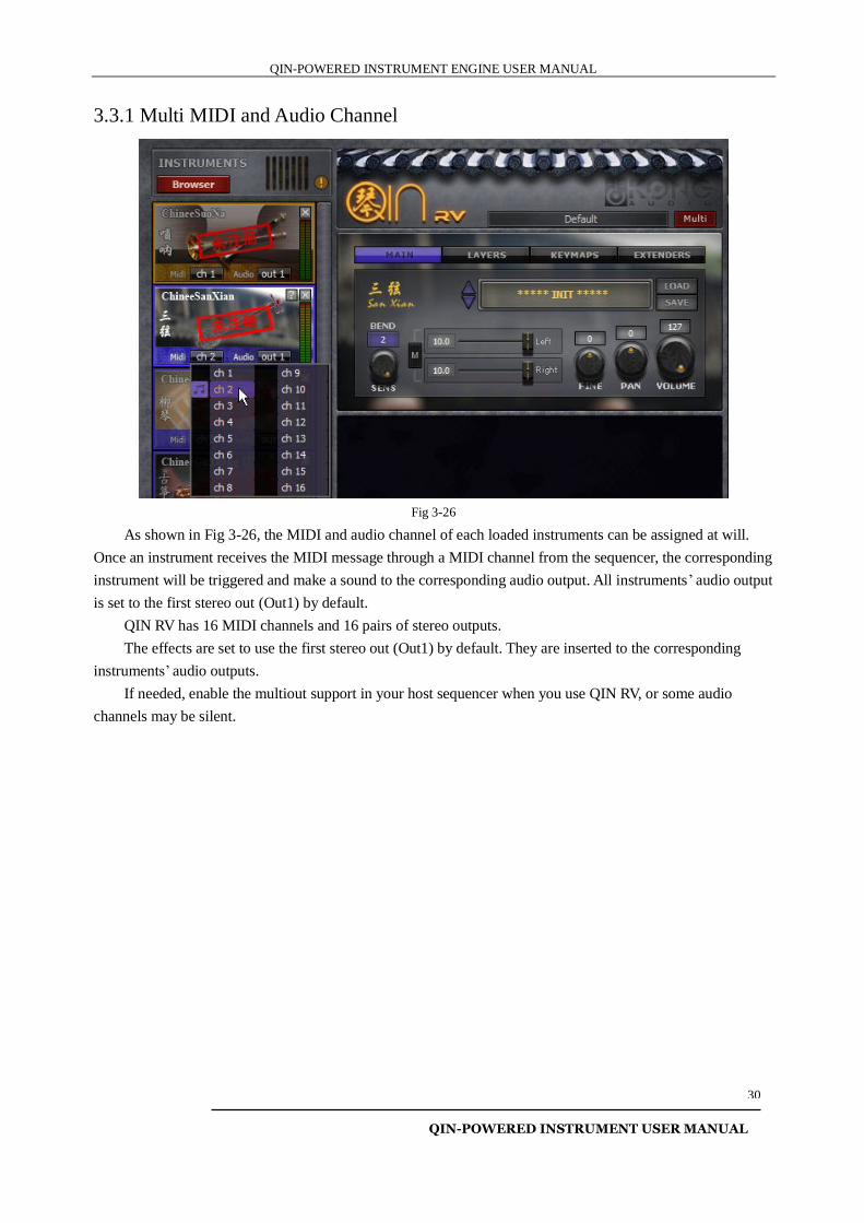
3.3.1 Multi MIDI and Audio Channel
Fig 3-26
As shown in Fig 3-26, the MIDI and audio channel of each loaded instruments can be assigned at will.
Once an instrument receives the MIDI message through a MIDI channel from the sequencer, the corresponding
instrument will be triggered and make a sound to the corresponding audio output. All instruments’ audio output
is set to the first stereo out (Out1) by default.
QIN RV has 16 MIDI channels and 16 pairs of stereo outputs.
The effects are set to use the first stereo out (Out1) by default. They are inserted to the corresponding
instruments’ audio outputs.
If needed, enable the multiout support in your host sequencer when you use QIN RV, or some audio
channels may be silent.
QIN-POWERED INSTRUMENT ENGINE USER MANUAL
QIN-POWERED INSTRUMENT USER MANUAL
31
Chapter Four: Combining the Extenders
In this chapter we will show you how to combine the Extenders to get advanced performances. You can
try to explore more possibilities by experimenting with the Exts yourself.
4.1 Speed Detection and Legato
Now we have a legato patch which has three subsets, and two of them are in a legato group, and we want
these two to be triggered by different playing speed. To make this happen, we need to combine both Legato
Assignment and Speed Detection Extenders.
Subset setup: Load up Subset Loader 01 with the "NORMAL" subset, Subset Loader 02 with the subset
"Legato Quick"; Subset Loader 03 with the subset "Legato Slow".
Legato setup: Subset Loader 01 assigned to "Normal", Subset loader 02, 03, assigned to "Up" or "Down"
(Here we only need to show the difference between Legato/non-legato mode, so either of the Up or the Down
group will do. In other words, either Normal-up or the Normal-down's non-legato/legato mode will do).
Speed Detection setup. Subset Loader 01 assigned to "Thru"; Subset Loader 02 to "Quick"; Subset
Loader 03 to "Slow". Both Speed Detector bars have the same bar values, in the Quick-Slow group (i.e.,
Tempo 120, then set to 500 ms).
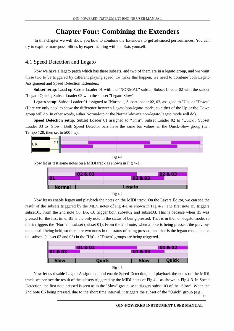
Fig 4-1
Now let us test some notes on a MIDI track as shown in Fig 4-1.
Fig 4-2
Now let us enable legato and playback the notes on the MIDI track. On the Layers Editor, we can see the
result of the subsets triggered by the MIDI notes of Fig 4-1 as shown in Fig 4-2: The first note B5 triggers
subset01. From the 2nd note C6, B5, C6 trigger both subset02 and subset03. This is because when B5 was
pressed for the first time, B5 is the only note in the status of being pressed. That is in the non-legato mode, so
the it triggers the "Normal" subset (subset 01). From the 2nd note, when a note is being pressed, the previous
note is still being held, so there are two notes in the status of being pressed, and that is the legato mode, hence
the subsets (subset 02 and 03) in the "Up" or "Down" groups are being triggered.
Fig 4-3
Now let us disable Legato Assignment and enable Speed Detection, and playback the notes on the MIDI
track, we can see the result of the subsets triggered by the MIDI notes of Fig 4-1 as shown in Fig 4-3. In Speed
Detection, the first note pressed is seen as in the "Slow" group, so it triggers subset 03 of the "Slow". When the
2nd note C6 being pressed, due to the short time interval, it triggers the subset of the "Quick" group (e.g.,
QIN-POWERED INSTRUMENT ENGINE USER MANUAL
QIN-POWERED INSTRUMENT USER MANUAL
32
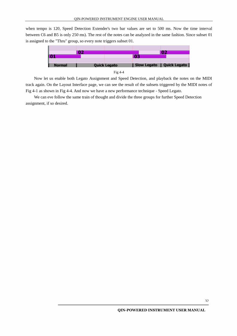
when tempo is 120, Speed Detection Extender's two bar values are set to 500 ms. Now the time interval
between C6 and B5 is only 250 ms). The rest of the notes can be analyzed in the same fashion. Since subset 01
is assigned to the "Thru" group, so every note triggers subset 01.
Fig 4-4
Now let us enable both Legato Assignment and Speed Detection, and playback the notes on the MIDI
track again. On the Layout Interface page, we can see the result of the subsets triggered by the MIDI notes of
Fig 4-1 as shown in Fig 4-4. And now we have a new performance technique - Speed Legato.
We can eve follow the same train of thought and divide the three groups for further Speed Detection
assignment, if so desired.
QIN-POWERED INSTRUMENT ENGINE USER MANUAL
QIN-POWERED INSTRUMENT USER MANUAL
33
Chapter Five: Product Authorization
This chapter explains how to authorize QIN plugins, and you will find some detailed info about the
registration mechanism.
5.1 How to Authorize the Instrument
First, purchase a license and check your User ID (See Section 5.1.1.), then send your User ID and your
name to Kong Audio's personnel ([email protected]), and you will receive your xml keyfile within a work
day.. More detailed explanation follows:
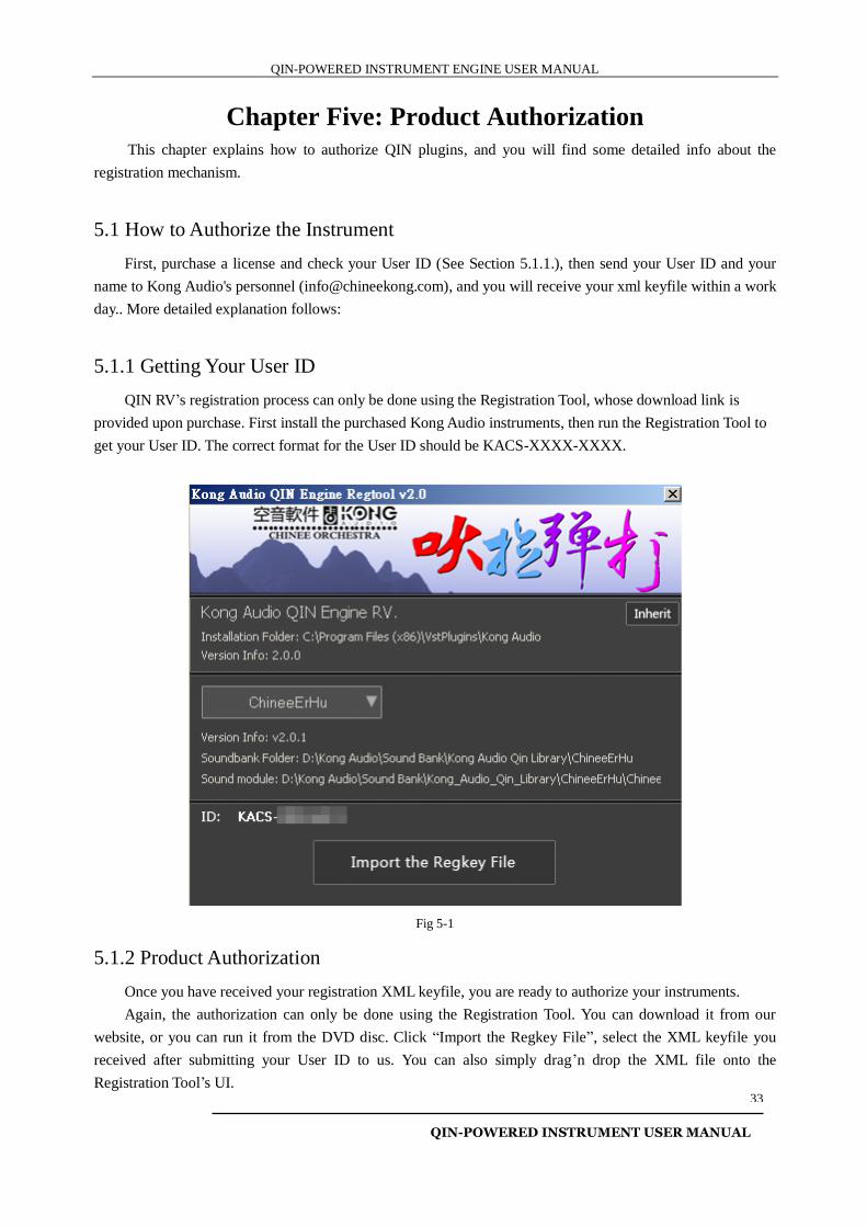
5.1.1 Getting Your User ID
QIN RV’s registration process can only be done using the Registration Tool, whose download link is
provided upon purchase. First install the purchased Kong Audio instruments, then run the Registration Tool to
get your User ID. The correct format for the User ID should be KACS-XXXX-XXXX.
Fig 5-1
5.1.2 Product Authorization
Once you have received your registration XML keyfile, you are ready to authorize your instruments.
Again, the authorization can only be done using the Registration Tool. You can download it from our
website, or you can run it from the DVD disc. Click “Import the Regkey File”, select the XML keyfile you
received after submitting your User ID to us. You can also simply drag’n drop the XML file onto the
Registration Tool’s UI.
QIN-POWERED INSTRUMENT ENGINE USER MANUAL
QIN-POWERED INSTRUMENT USER MANUAL
34
The instruments will only show up with “unregistered” markings removed AFTER reloading the
instruments.
NOTE: Make sure the plugins are properly installed and usable prior to authorization. Manually moving/copying the installed
files can very well cause problems very easily. Please avoid manually organizing QIN RV.
If you already have QIN v1.0 instruments installed, you can use the “inherit” button to import the authorization and the
soundbank path info to QIN RV.
5.2 Authorization Mechanism
If you have any further questions about the authorization mechanism, you can get more info from this
Section. You will find more info about the failed registration attempts too.
5.2.1 User ID
User ID is a machine code. Each PC has its own unique machine code, tied to hardware parts. Change of
motherboard, CPU, or having a BIOS flash, can cause a change of USER ID. On the other hand, a change of
RAM, network card, graphic card, or your screen monitor will not affect the USER ID.
User ID is used for verifying the legitimacy of the serial code in the authorization mechanism. Please note,
a legitimate serial number does not equal to successful authorization. See 5.2.2 for more info on the serial code.
User ID is also used for generating the serial code from the official authorization end.
5.2.2 Serial Code
A legitimate serial code is comprised of 9 sets of segments, and each set contains 5 digits or syllables. An
official serial code is generated by the authorization end based on User ID and User Name.
An official serial does not contain the letter "I", "O", digit "0" and "1". The letter-case does not matter.
Serial code is the crucial part of the authorization mechanism. A serial code contains 45 valid characters
with 23 messages. The messages contain info used for UI markings, noise-burst, sound-encryption, function
parameters etc. So you have one-32nd power of 45's chance to combine the digits and the alphabets as an
unofficial serial number and register the plugin with it, and the "UNREGISTERED" markings on the banner
will disappear, but the noise-burst is still there, and the sound is awkward, that's because the serial number only
contains the valid info for the UI marking. The chance of you ever run into such a situation is extremely tiny,
because unofficial serial is very unlikely to pass through the validation mechanism.
So you may have another question: how do you know you are properly authorized even if you use official
serial code, and with the UI markings gone? You need not to worry about it. As long as you use official serial
code, the disappearance of "UNREGISTERED" markings means it is properly authorized. Even if for some
reason (such as the change of User ID) the serial code does not work, the "UNREGISTERED" markings will
not disappear. The official serial code contains info to prevent this from happening.
5.2.3 User Name
User Name functions similar to User ID. It is used for verifying the legitimacy of the serial code on the
QIN-POWERED INSTRUMENT ENGINE USER MANUAL
QIN-POWERED INSTRUMENT USER MANUAL
35
user end.
5.2.4 Sound Decryption
The sound of the instrument is encrypted, and it requires the right key for decryption. If the sound is not
decrypted, pitch variation and sound distortion will be heard upon playback. The sound decryption key is
dynamically generated and it decrypts the sound in real time, and it is not the only one encryption, so every
time when the plugin is executed the decryption key can be different. Most of its messages come from serial
code's sound decryption message, so the decrypted sound will be perceived as abnormal and distorted if it is
not properly decrypted.
This is the true way to tell whether a plugin is legitimately authorized.
5.2.5 Noise Burst
Noise burst is intermittent, and it means that the product is missing some function parameters. These
parameters are obtained through the serial code. If somehow the noise burst is hacked through brutal cracking
of the plugins, it does not mean the parameters are there. In a proper product purchased through the official
vendor, the noise burst only means that the product is not properly authorized yet. If necessary, you may obtain
a special serial code to remove the noise-burst, yet still remains unregistered. We do not provide this serial
code under normal situations.
The removal of noise burst is another true way to tell whether a plugin is legitimately authorized.
5.2.6 Successful Authorization
The product shows the registration status though the UI hints (e.g., the "UNREGISTER" markings on the
main logo banner), intermittent noise-burst, and sound indication (distortion and pitch changing). Once
properly authorized, the backpanel will display registered user info. All in all, everything will work as it should
be once properly authorized.
5.3 FAQ
Q: How do I authorize the product?
A: Check 5.1, 5.1.1, 5.1.2 for instructions.
Q: How do I know whether the product is properly authorized?
A: See 5.2.6
Q: Why my authorization failed even though I have entered the regcode?
A: Please check again carefully whether you have entered the regcode correctly. Use copy/paste to avoid
possible human errors. Be sure not to include any space before and after the name/code. If it still does not work,
please verify if the User ID you sent us matches the User ID you are seeing now. If it still does not work,
please contact us directly for further support.
Q: Why the plugins are suddenly no longer authorized?
QIN-POWERED INSTRUMENT ENGINE USER MANUAL
QIN-POWERED INSTRUMENT USER MANUAL
36
A: There are some possible causes that may disturb the authorization mechanism. It is usually caused by a
change of the working environment, such as the change of hardware parts, the change of system times, etc. You
can contact us for support and we will help you work out the issue.
Q: Why do I hear weird sound from the instrument?
A: The authorization mechanism does not check for the validity of the serial code other than simple
verification, and it does not verify the encrypted key for the sound. An incorrect decryption key will cause
unpredictable sound result. In other words, an incorrect serial code is causing the issue. Please delete the XML
files under the product folder, and then reconfigure the plugin, re-authorization, reset the sample folder etc.
CODA
Here we have explored a small portion of QIN Engine's potentials. There are many more possible ways to
combine the subsets and the Extenders to create your own unique playing style or sound, and to make it your
own instrument.
QIN Engine is an ongoing project. QIN RV is another step forward since the release of the original QIN
v1.0. We will keep on improving QIN to meet our own needs for developing more articulating, more realistic
Chinese instruments. We can use all the suggestions and feedback from you. Please do not hesitate to share
with us your thoughts, so we may keep on bringing you better products and better experience in the future.
Thank you, once again, for your support of Kong Audio in developing the sound content and the
technology required to fulfilling both yours and our dreams for making better music.
Recommended