KUWAIT OIL COMPANY (K.S.C.)
STANDARDS PUBLICATION
KOC RECOMMENDED PRACTICE
FOR
EXTERNAL C ODIC PROTECTION OF ON-GRADE NEW STEEL TANK BOTTOM
I STANDARDSTEAM I
KUWAIT OIL COMPANY (K.S.C.)
STANDARDS PUBLICATION
KOC RECOMMENDED PRACTICE
FOR
EXTERNAL CATHODIC PROTECTION OF ON-GRADE NEW STEEL TANK BOTTOM
STANDARDS TEAM -
REV. 2 DOC. NO. KOC-L-026 Page 1 of 31
DOC. NO. KOC-L-026 Page 2 of 31 REV. 2
KOC RECOMMENDED PRACTICE
FOR
EXTERNAL CATHODIC PROTECTION OF ON-GRADE NEW STEEL TANK BOTTOM
ISSUING AUTHORITY:
STANDARDS TEAM
2 14/08/2006 Issued as KOC RP Task Force ( T F-CP102 )
\ Rev. Date Description Prepared by Snr. Engr. Standards Ag. T m Leader Standards
Tel61407 Tel. 61896
TABLE OF CONTENTS
FOREWORD
SCOPE
APPLICATION
TERMINOLOGY 3.1 Definitions 3.2 Abbreviations
REFERENCE STANDARDS AND CODES 4.1 Conflicts 4.2 List of Standards and Codes
ENVIRONMENTAL CONDITIONS
HEALTH, SAFETY AND ENVIRONMENT
CATHODIC PROTECTION SYSTEM DESIGN 7.1 Objective 7.2 Design Life 7.3 Potential Range 7.4 Current Requirement and Density 7.5 Membrane Liner 7.6 Tank Bottom Soil Backfill 7.7 Reference Electrodes 7.8 Electrical Continuity1 Isolation 7.9 Electrical Connections 7.10 Cathodic Protection for Tanks During Tank Bottom
Replacement
CATHODIC PROTECTION DESIGNER & INSTALLER
MATERIALS & EQUIPMENT REQUIREMENTS 9.1 Selection of Equipment and Materials 9.2 Anodes 9.3 Titanium Conductor 9.4 Cables 9.5 Transformer Rectifier (TIR) 9.6 Junction Boxes 9.7 Reference Electrodes
Page No.
5
7
7
7 7 8
9 9 9
10
10
11 11 11 12 12 12 12 13 13 14
14
14
14 14 14 15 15 15 16 16
INSTALLATION OF CP SYSTEM 16
PRE-COMMISSIONING & FINAL COMMISSIONING 17 11.2 Natural Potential 17 11.3 Preliminary Adjustment 18 I 1.4 Potential Measurement 18 11.5 Interference Testing 18 11.6 Final Commissioning 18
QUALITY ASSURANCE /QUALITY CONTROL 19
MARKING 19
CALCULATIONS AND DOCUMENTATION 19
AS BUILT DRAWING 20
APPENDICES 21-29
16.1 Appendix-A: Inspection and Test Plan for
Tank Bottom (Impressed Current
Cathodic Protection System) 21
16.2 Appendix- B: Check Lists for 22-28
- Tank Bottom Cathodic Protection
System (Grid System 1 - Reference Electrode Function Test
- Boxes (J. B and Test Box)
- TIR Rectifier Check List
- Pre-commissioning Checklist for Impressed
Current Cathodic Protection S y s t e ~
(New Tank Bottom External)
- Tank Bottom CP Summary Data Sheet
16.3 Appendix -C: Drawing No. CP-002 :
Typical Cathodic Protection Details for
Underside of Tank Bottom Using
Grid System 29
ACKNOWLEDGMENT 30
FOREWORD
The document "KOC Recommended Practice for External Cathodic Protection of On-Grade New Steel Tank Bottom (Rev.1)" has been revised to incorporate latest practices and current requirements for CP systems to be followed with a view to ensure better functions, reliability, inspection and maintenance of new steel tank bottom CP system within KOC Facilities.
This KOC RP (Rev.2) has been approved by Standards Team in consultation with Standards Technical Committee (STC) for consistent use throughout the corporate engineering and operational functions of Kuwait Oil Company (K.6.C).
The purpose of this RP sets out to achieve the following objectives:
a. To describe current technical practices in industry and general procedures for establishing cathodic protection system in order to minimize corrosion of the external surfaces of steel tank bottom that is in contact with ground.
b. To provide general technical input and guidance for developing project specifications with a view to ensure quality, safety and reliability.
c. To set out minimum requirements and guidance for monitoring compliance of materials and testing.
d. To act as a tool for internal communication from which future safety, environmental and technological changes can be measured.
Feedback as well as any comments or suggestions derived from the application of this RP at any stage of design, construction, maintenance and figld experiences are encouraged and should be directed to:
The Team Leader Standards
(Chairman, Standards Technical Committee)
P.O.Box-9758, Ahmadi 61 008
State of Kuwait
II I DOC. NO. KOC-L-026 Page 6 of 31 REV. 2
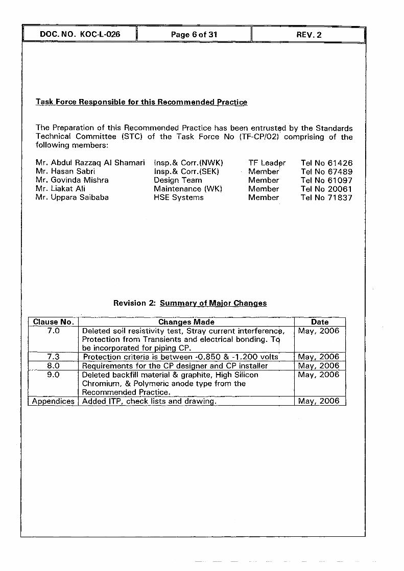
Task Force Responsible for this Recommended Practice
The Preparation of this Recommended Practice has been entrusted by the Standards Technical Committee (STC) of the Task Force No (TF-CPI021 comprising of the following members:
Mr. Abdul Razzaq A1 Shamar Mr. Hasan Sabri Mr. Govinda Mishra Mr. Liakat Ali Mr. Uppara Saibaba
.i Insp.& Corr.(NWK) TF Leader Tel No 6 1 426 Imp.& Corr.(SEK) Member Tel No 67489 Design Team Member Tel No 61 097 Maintenance (WK) Member Tel No 20061 HSE Systems Member Tel No 7 1 837
Revision 2: Summarv of Maior Changes
Clause No. 7 .O
7.3 8 .O 9 .O
Appendices
Changes Made Deleted soil resistivity test, Stray current interference, Protection from Transients and electrical bonding. Tq
Date May, 2006
be incorporated for piping CP. I Protection criteria is between -0.850 & -1.200 volts Requirements for the CP designer and CP installer Deleted backfill material & graphite, High Silicon Chromium, & Polymeric anode type from the Recommended Practice. Added ITP, check lists and drawing.
May, 2006 May, 2006 May, 2006
May, 2006
SCOPE
This Recommended Practice (RP) covers the minimum general requirements for system design, equipment, material, installation, inspection 1 testing and commissioning of permanent impressed current cathodic protection systems, with a view to minimize corrosion from the external surface of on-grade steel tank bottom in contact with soil, by providing adequate external protection to new steel storage tank bottoms.
This document is for guidance only and does not desigqate specific system design or practices for every application. Therefore, the CP system designer shall investigate all system requirements and other pre-design requisites such as tank design, tank bottom materials, tank size, etc.
APPLICATION
The materials, equipment, system design, installation, ingpectionltesting and commissioning of cathodic protection (CP) system for tank bottoms shall conform to the requirement of this Recommended Practiqe and the reference standardslcodes mentioned herein.
Any exceptions or deviations from this document, along p i t h their merits and justifications, shall be brought to the attention of KOC controlling Team for their review, consideration and amendment by Standards Team (if required).
Compliance with this KOC Recommended Practice does not of itself confer immunity from legal or statutory obligations.
TERMINOLOGY
Definitions
For the purpose of this RP, the following definitions apply.
Cathode
The electrode of an electrochemical cell at which reduction occurs.
Cathodic Protection
A technique to reduce the corrosion of a metal surfqce by making that surface the cathode of an electrochemical cell.
Current Density
The current flowing to or from a unit area of an electrode surface.
DOC. NO. KOC-L-026 I Page 7 of 31 I REV. 2
- -
Electrical Isolation
The condition of being electrically separated from other metallic structures or the environment.
Foreign Structure
Any metallic structure that is not intended as part of cathodic protection system.
Impressed Current
Direct current (DC) supplied t o a CP system by an external power source such as rectified commercial AC, batteries or electric generators.
Membrane Liner
A thin, continuous sheet of non-conductive material (palyethylene) installed beneath the storage tank bottom in or on the pad tank foundation, to contain any accidentally escaped product.
On-Grade Storage Tank
A tank constructed on sand or earthen pads, concrete ringwalls, or concrete pads.
Reference Electrode
An electrode whose open-circuit potential is constant under similar conditions of measurement, which is used for meqsuring the relative potentials of other electrodes.
Stray-Current Corrosion
Corrosion resulting from current through paths other than the intended circuit, e.g., by any extraneous current in the earth.
Abbreviations
AJB CP DC HSE ICCP ITP JB KOC MMO TIR
Anode Junction Box Cathodic Protection Direct Current Health Safety and Environment Impressed Current Cathodic Protection Inspection and Test Plan Junction Box Kuwait Oil Company (K.S.C.) Metal Mixed Oxide Transformer Rectifier.
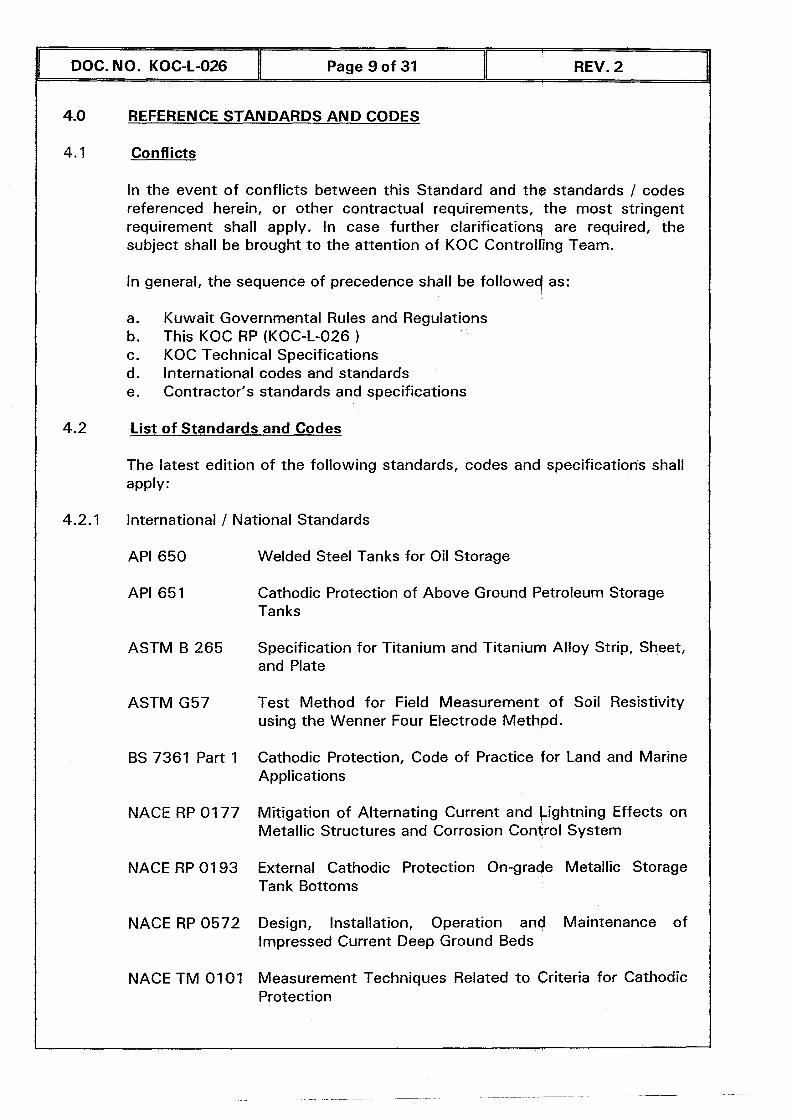
4.0 REFERENCE STANDARDS AND CODES
In the event of conflicts between this Standard and the standards / codes referenced herein, or other contractual requirements, the most stringent requirement shall apply. In case further clarificationg are required, the subject shall be brought to the attention of KOC Controlling Team.
In general, the sequence of precedence shall be followed as:
a. Kuwait Governmental Rules and Regulations b. This KOC RP (KOC-1-026 ) c. KOC Technical Specifications d. International codes and standards e. Contractor's standards and specifications
4.2 List of Standards and Codes
The latest edition of the following standards, codes and specifications shall apply:
4.2.1 International 1 National Standards
API 650
API 651
ASTM B 265
ASTM G57
BS 7361 Part 1
NACE RP 01 77
NACE RP 01 93
NACE RP 0572
NACE TM 0101
Welded Steel Tanks for Oil Storage
Cathodic Protection of Above Ground Petroleum Storage Tanks
Specification for Titanium and Titanium Alloy Strip, Sheet, and Plate
Test Method for Field Measurement of Soil Resistivity using the Wenner Four Electrode Methpd.
Cathodic Protection, Code of Practice for Land and Marine Applications
Mitigation of Alternating Current and Lightning Effects on Metallic Structures and Corrosion Control System
External Cathodic Protection On-grade Metallic Storage Tank Bottoms
Design, installation, Operation and Maintenance of Impressed Current Deep Ground Beds
Measurement Techniques Related to Criteria for Cathodic Protection
DOC. NO. KOC-L-026 I Page 9 of 31 I REV. 2
-
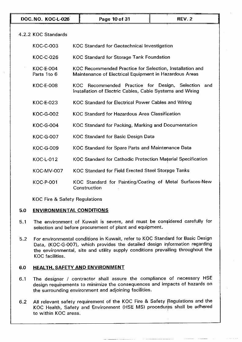
4.2.2 KOC Standards
DOC. NO. KOC-L-026 W Page 10 of 31
KOC-C-003
KOC-C-026
KOC-E-004 Parts 1 to 6
KOC-E-008
REV. 2
KOC Standard for Geotechnical Investigation
KOC Standard for Storage Tank Foundation
KOC Recommended Practice for Selection, Installation and Maintenance of Electrical Equipment in Hazardous Areas
KOC Recommended Practice for Design, Selection and lnstallation of Electric Cables, Cable Systems and Wiring
KOC Standard for Electrical Power Cables and Wiring
KOC Standard for Hazardous Area Classifipation
KOC Standard for Packing, Marking and Documentation
KOC Standard for Basic Design Data
KOC Standard for Spare Parts and Maintenance Data
KOC Standard for Cathodic Protection Material Specification
KOC Standard for Field Erected Steel Storgge Tanks
KOC Standard for PaintinglCoating of Metal Surfaces-New Construction
KOC Fire & Safety Regulations
ENVIRONMENTAL CONDITIONS
The environment of Kuwait is severe, and must be considered carefully for selection and before procurement of plant and equipment.
For environmental conditions in Kuwait, refer t o KOC Standard for Basic Design Data, (KOC-G-007), which provides the detailed design iqformation regarding the environmental, site and utility supply conditions prevailing throughout the KOC facilities.
HEALTH, SAFETY AND ENVIRONMENT
The designer / contractor shall assure the compliance of necessary HSE design requirements to minimize the consequences and impacts of hazards on the surrounding environment and adjoining facilities.
All relevant safety requirement of the KOC Fire & Safety Pegulations and the KOC Health, Safety and Environment (HSE MS) procedures shall be adhered to within KOC areas.
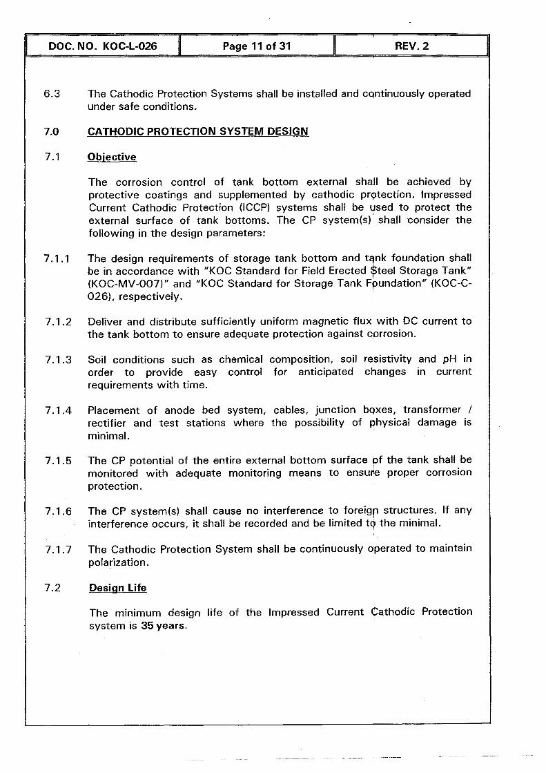
The Cathodic Protection Systems shall be installed and csntinuously operated under safe conditions.
DOC. NO. KOC-L-026
CATHODIC PROTECTION SYSTEM DESIGN
Obiective
Page 11 of 31
The corrosion control of tank bottom external shall be achieved by protective coatings and supplemented by cathodic prqtection. Impressed Current Cathodic Protection (ICCP) systems shall be used to protect the external surface of tank bottoms. The CP systemk) shall consider the following in the design parameters:
REV. 2
The design requirements of storage tank bottom and tqnk foundation shall be in accordance with "KOC Standard for Field Erected $tee1 Storage Tank" (KOC-MV-007)" and "KOC Standard for Storage Tank ~bundation" (KOC-C- 026), respectively.
Deliver and distribute sufficiently uniform magnetic flux with DC current to the tank bottom to ensure adequate protection against corrosion.
Soil conditions such as chemical composition, soil resistivity and pH in order to provide easy control for anticipated changes in current requirements with time.
Placement of anode bed system, cables, junction bqxes, transformer / rectifier and test stations where the possibility of ~hysical damage is minimal.
The CP potential of the entire external bottom surface pf the tank shall be monitored with adequate monitoring means to ensure proper corrosion protection.
The CP systern(s) shall cause no interference to foreigp structures. If any interference occurs, it shall be recorded and be limited t q the minimal.
The Cathodic Protection System shall be continuously operated to maintain polarization.
Design Life
The minimum design life of the Impressed Current cathodic Protection system is 35 years.
DOC. NO. KOC-L-026 I Page 12 of 31 11 REV. 2
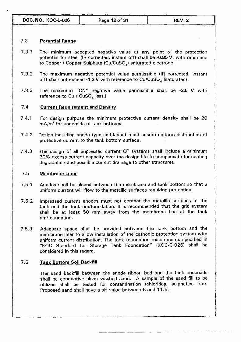
Potential Ranqe
The minimum accepted negative value at any point of the protection potential for steel (IR corrected, instant off) shall be -0.85 V, with reference to Copper / Copper Sulphate (CuICuSO,) saturated electrode.
The maximum negative potential value permissible (IS corrected, instant off) shall not exceed -1.2 V with reference t o CuICuSO, (saturated).
The maximum "ON" negative value permissible shqll be -2.5 V with reference t o Cu I CuSO, (sat.)
Current Reauirement and Densitv
For design purpose the minimum protective current density shall be 2 0 r n ~ l m * for underside of tank bottoms.
Design including anode type and layout must ensure un/forrn distribution of protective current t o the tank bottom surface.
The design of all impressed current CP systems shall include a minimum 30% excess current capacity over the design life t o compensate for coating degradation and possible current drainage to other structures.
Membrane Liner
Anodes shall be placed between the membrane and tank bottom so that a uniform current will f low to the metallic surfaces requiriqg protection.
Impressed current anodes must not contact the metallic surfaces of the tank and the tank rimlfoundation. It is recommended that the grid system shall be at least 5 0 mm away from the membrane line at the tank rimlfoundation.
Adequate space shall be provided between the tank bottom and the membrane liner to allow installation of the cathodic prolection system with uniform current distribution. The tank foundation requi&ments specified in "KOC Standard for Storage Tank Foundation" (KOC-C-026) shall be considered in this regard.
Tank Bottom Soil Backfill
The sand backfill between the anode ribbon bed and the tank underside shall be conductive clean washed sand. A sample of the sand fill t o be utilized shall be tested for contamination (chlorides, sulphates, etc). Proposed sand shall have a pH value between 6 and 11.5.
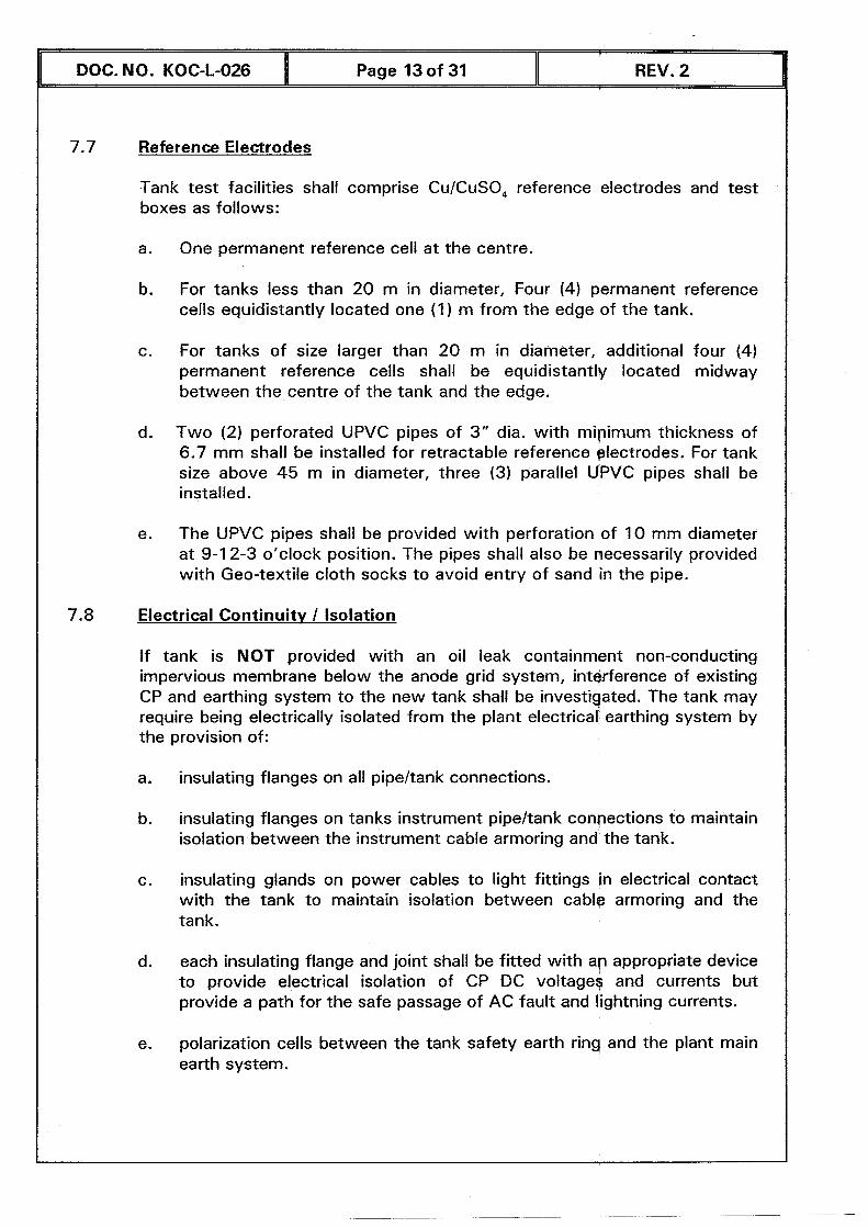
7.7 Reference Electrodes
DOC. NO. KOC-L-026 I Page 13 of 31
Tank test facilities shall comprise CuICuSO, reference electrodes and test boxes as follows:
REV. 2
a. One permanent reference cell at the centre.
b. For tanks less than 20 m in diameter, Four (4) permanent reference cells equidistantly located one (1) m from the edge of the tank.
c. For tanks of size larger than 20 m in diameter, additional four (4) permanent reference cells shall be equidistantly located midway between the centre of the tank and the edge.
d. Two (2) perforated UPVC pipes of 3" dia. with mipimum thickness of 6.7 mm shall be installed for retractable reference electrodes. For tank size above 45 m in diameter, three (3) parallel UPVC pipes shall be installed.
e. The UPVC pipes shall be provided with perforation of 10 mm diameter at 9-1 2-3 o'clock position. The pipes shall also be necessarily provided with Geo-textile cloth socks to avoid entry of sand in the pipe.
7.8 Electrical Continuitv I Isolation
If tank is NOT provided with an oil leak containment non-conducting impervious membrane below the anode grid system, intgrference of existing CP and earthing system to the new tank shall be investigated. The tank may require being electrically isolated from the plant electrical' earthing system by the provision of:
a. insulating flanges on all pipeltank connections.
b. insulating flanges on tanks instrument pipeltank connections to maintain isolation between the instrument cable armoring and the tank.
c. insulating glands on power cables to light fittings in electrical contact with the tank to maintain isolation between cable armoring and the tank.
d. each insulating flange and joint shall be fitted with ap appropriate device to provide electrical isolation of CP DC voltage$ and currents but provide a path for the safe passage of AC fault and lightning currents.
e. polarization cells between the tank safety earth ring and the plant main earth system.

DOC. NO. KOC-L-026 Page 14 of 31 I REV. 2
Electrical Connections
The cable connections to tank shell shall be by means of bolted cable iug connections to carbon steel plates welded to the structure. The steel plates shall be welded to the structure prior to the application of coating. The steel plate and weld method shall be compatible with the structure material. The steel plate coating shall be removed to facilitate the bolted cable connection. Only highly rated pure Brass bolts and nuts $hall be used.
Cathodic Protection for Tanks Durinq Tank Bottom Re~lacement
This Recommended Practice can be utilized for existing tank if the tank bottom is being replaced.
Information on the degree of the tank bottom corrosion is useful for the design of the Cathodic Protection.
Necessary modifications shall be carried out to the lank foundations in order to install the cables.
CATHODIC PROTECTION DESIGNER & INSTALLER
The design and installation of the Cathodic Protection Systems shall be carried out by a cathodic protection specialized pre-qualified Contractor, and shall be approved by KOC.
The design and commissioning of cathodic protection systems shall be carried out by a Cathodic Protection Specialist Engineer (NACE certified as CP-Specialist or equivalent).
A NACE certified Technician of Level ll (or equivalent) shall present at all time at site to supervise and report periodically the installation of all parts of the cathodic protection system.
MATERIALS & EQUIPMENT REQUIREMENTS
Selection of Equipment and Materials
All necessary CP materials shall be as per "KOC Stqndard for Cathodic Protection Material Specification" (KOC-1-0 1 2).
Anodes
The anode material shall be catalyzed Titanium anode ribbon coated with highly conductive Mixed Metal Oxide (MMO). The Titanium base shall be of ASTM 9265 Gradel. MMO shall comprise a mixture of ljidium and Tantalum oxides. Vendor shall provide technical data sheet of The proposed MMO anode clearly mentioning the oxides, MMO applic$tion method, and thickness of the MMO, breakdown voltage across the substrate oxide and maximum voltage across the MMO film.
1 DOC. NO. KOC-L-026 I Page 15 of 31 ll REV. 2
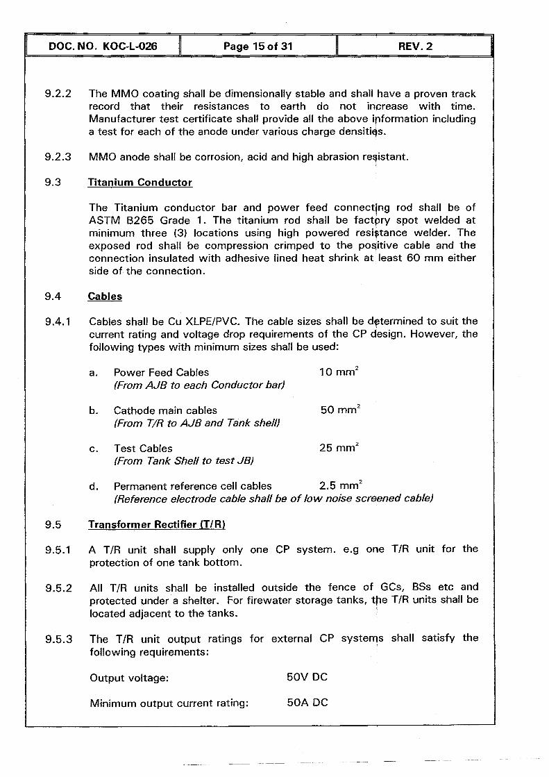
Minimum output current rating: 50A DC
L
The MMO coating shall be dimensionally stable and shall have a proven track record that their resistances to earth do not increase with time. Manufacturer test certificate shall provide all the above ipformation including a test for each of the anode under various charge densitigs.
MMO anode shall be corrosion, acid and high abrasion registant.
Titanium Conductor
The Titanium conductor bar and power feed connecting rod shall be of ASTM B265 Grade 1. The titanium rod shall be factpry spot welded a t minimum three (3) locations using high powered resiqtance welder. The exposed rod shall be compression crimped t o the positive cable and the connection insulated with adhesive lined heat shrink at least 6 0 m m either side of the connection.
Cables
Cables shall be Cu XLPEIPVC. The cable sizes shall be determined to suit the current rating and voltage drop requirements of the CP design. However, the following types with minimum sizes shall be used:
a. Power Feed Cables 10 mm2 (From AJB to each Conductor bar)
b. Cathode main cables 50 mm2 (From T/R to AJB and Tank shell)
c. Test Cables 25 mm2 (From Tank Shell to test JBI
d. Permanent reference cell cables 2.5 mm2 (Reference electrode cable shall be of low noise screened cable)
Transformer Rectifier (T/R)
A TIR unit shall supply only one CP system. e.g one TIR unit for the protection of one tank bottom.
AH TIR units shall be installed outside the fence of GCs, BSs etc and protected under a shelter. For firewater storage tanks, tbe T/R units shall be located adjacent t o the tanks.
The T/R unit output ratings for external CP systeqs shall satisfy the following requirements:
Output voltage: 50V DC
DOC. NO. KOC-L-026 Page 16 of 31
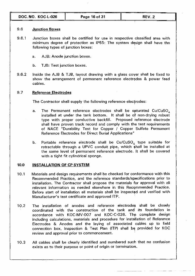
9.6 Junction Boxes
9.6.1 Junction boxes shall be certified for use in respective classified area with minimum degree of protection as 1P55: The system dqsign shall have the following types of junction boxes:
a. AJB: Anode junction boxes.
b. TJB: Test junction boxes.
9.6.2 Inside the AJB & TJB, layout drawing with a glass cover shall be fixed to show the arrangement of permanent reference electrgdes & power feed cables.
9.7 Reference Electrodes
The Contractor shall supply the following reference elecjrodes:
a. The Permanent reference electrodes shall be saturated Cu/CuSO, installed at under the tank bottom. It shall be of non-drying robust type with proper conductive backfill. Proposed reference electrode shall have proven track record and comply with the test requirements of NACE "Durability Test for Copper I Copper Sulfate Permanent Reference Electrodes for Direct Burial Applications"
b. Portable reference electrode shall be CuICuSO, type suitable for retractable through a UPVC conduit pipe, which shall be installed at the same level of permanent reference electrode. It shall be covered with a tight f i t cylindrical sponge.
10.0 INSTALLATION OF CP SYSTEM
10.1 Materials and design requirements shall be checked for conformance with this Recommended Practice, and the reference standardsls~ecifications prior to installation. The Contractor shall propose the materials for approval with all relevant information as needed elsewhere in this Recommended Practice. Before start of installation all materials shall be inspectgd and verified with Manufacturer's test certificate and approved ITP.
10.2 The installation of anodes and reference electrode? shall be closely coordinated with the construction of the tank and its foundation in accordance with KOC-MV-007 and KOC-C-026. The complete design including calculations, materials and procedure for installation of Reference Electrodes & Anodes and the laying of associated cables up to field connection box, Inspection & Test Plan (1TP) shall bq provided for KOC review and approval prior to commencement.
10.3 All cables shall be clearly identified and numbered such that no confusion exists as to their purpose or point of origin or termination.
DOC. NO. KOC-L-026 1 Page 17 of 31 1 REV. 2
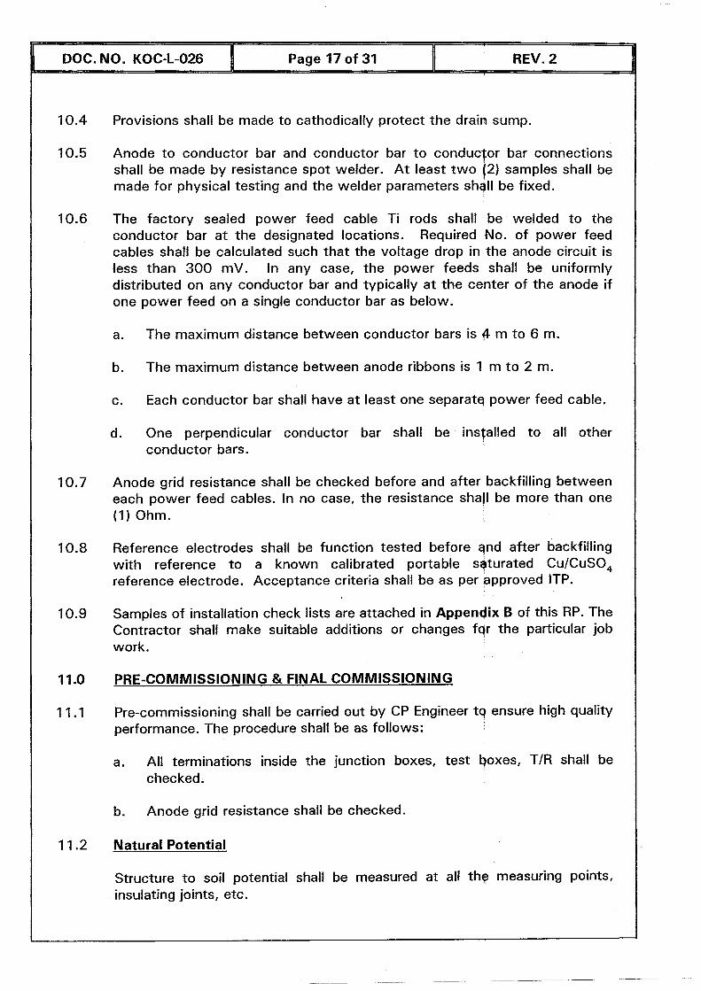
Provisions shall be made to cathodicafly protect the drain sump.
Anode to conductor bar and conductor bar to conduclor bar connections shall be made by resistance spot welder. A t least two (2) samples shall be made for physical testing and the welder parameters shall be fixed.
The factory sealed power feed cable Ti rods shall be welded to the conductor bar at the designated locations. Required No. of power feed cables shall be calculated such that the voltage drop in the anode circuit is less than 300 mV. In any case, the power feeds shall be uniformly distributed on any conductor bar and typically at the center of the anode if one power feed on a single conductor bar as below.
a. The maximum distance between conductor bars is 4 m to 6 m.
b. The maximum distance between anode ribbons is 1 m to 2 m.
c. Each conductor bar shall have at least one separatq power feed cable.
d. One perpendicular conductor bar shall be installed to all other conductor bars.
Anode grid resistance shall be checked before and after backfilling between each power feed cables. In no case, the resistance shall be more than one (1) Ohm.
Reference electrodes shall be function tested before qnd after backfilling with reference to a known calibrated portable sqturated CuICuSO, reference electrode. Acceptance criteria shall be as per approved ITP.
Samples of installation check lists are attached in Appendix 8 of this RP. The Contractor shall make suitable additions or changes fqr the particular job work.
PRE-COMMISSIONING & FINAL COMMISSIONING
Pre-commissioning shall be carried out by CP Engineer t q ensure high quality performance. The procedure shall be as follows:
a. All terminations inside the junction boxes, test boxes, T/R shall be checked.
b. Anode grid resistance shall be checked.
Natural Potential
Structure t o soil potential shali be measured at all the measuring points, insulating joints, etc.
DOC. NO. KOC-1-026 I Page 18 of 31 I REV. 2
1 I .3 Preliminary Adiustment
Before energizing, the T/R output shall be kept at 10% of design current output. After 48 hours, potential shall be measured and the output shall be increased, if required to meet the following criteria.
a. It is required that the midpoint potentials shall not be less negative than -0.850 V (IR corrected, instant off) with referencg to Cu/CuSO, (sat.) and the station current outputs shall then be adjusted to achieve the required midpoint potential.
b. The current output shall not be increased to produce a more negative potential at the drain point greater than -1.2 V volts (IR corrected, instant off) with reference to Cu/CuSO, (sat.).
11.4 Potential Measurement
Following the adjustment of cathodic protection station putputs to meet the structure to soil potentials, a complete set of potentials shall be recorded at all the measuring points and other positions measured earlier.
1 1.5 Interference Testing
11.5.1 The Contractor shall perform all interference testing and shall be fully responsible for contacting all the responsible Authorities and arranging for their presence at all required tests.
1 1 -5.2 Should any interference test results show a positive chqnge in the potential of a foreign installation or structure of more than 20 mV, the Contractor shall take remedial action to eliminate the interaction.
1 1.6 Final Commissioning
Final commissioning shall consist of:
Measuring tank to soil potentials at all measuring points.
Measuring total current output from each station and the current in each direction where current measurements are possible.
Measuring settings of power sources: transformer/ rgctifiers.
Measuring current and resistance if remedial bond fitfed.
Calibrating all current measurement points.
DOC. NO. KOC-L-026 I Page 19 of 31 I REV. 2
QUALITY ASSURANCE /QUALITY CONTROL
The Manufacturer/Contractor shall operate a quality system to ensure that the requirements of this Recommended Practice are achieved, The quality system shall be preferably based on IS0 9000 series of standards and the Manufacturer/Contractor shall demonstrate compliance by providing a copy of the accredited certificate or the manufacture's / contractor's quality manual.
Verification of the Manufacturer's / Contractor's quality system is normally part of the pre-qualification procedure, and it is therefore not detailed in the core text of this document.
The Contractor shall submit their Quality System Manual & Quality Assurance Plan that include all the activities in chronological order with responsibilities. Inspection & Test Plan (ITP) for CP system installation and commissioning shall be submitted for KOC approval. Columns shall be provided so that KOC can mark up its "Witness" (W) points and "Hold" (H) points.
A sample ITP is attached in Appendix A which is only typical; and the Contractor shall make suitable additions or changes f ~ r the particular job work.
MARKING
For all relevant requirements and on Marking / Packing refer to "KOC Standard for Packing, marking and Documentation" (KOC-G-004).
CALCULATIONS AND DOCUMENTATION
All correspondence, drawings, instructions, data sheets, design calculations, or any other written information shall be in English Langgage. In the case of dual languages, one language shall be English.
All dimensions, units or measurements, physical constant, etc, shall be in SI units, unless otherwise specified.
Deliverables
The following documentation, drawings, inspection & test plans and check lists shall be submitted for approval:
a. Schematic drawing of the entire CP systems b. Anode ground bed detail drawings c. T/R unit electrical schematic diagrams d. T/R unit general arrangement and mounting detail drawings e. CP equipment layout drawing
CP cable layout drawing & sizing, color schedule Test facility detail drawings Junction boxes and support stands construction drayvings Junction boxes termination drawings Cable connection detail drawings CP electrical installation specification Installation procedure Pre-commissioning procedures Operation and maintenance procedures Inspection & Test Plan.
DOC. NO. KOC-L-026 Page 20 of 31
14.4 CP calculations shall include:
a. Protected structure CP current demand b. Foreign structure CP drain currents c. Soil resistivity calculations d. Ribbon anode length, No. of conductor bars, power feed cables, Anode
grid system & cable resistance, output current, voltage drop calculations e. Maximum Anode current density based on maximum current density and
Spacing f. Anode life g. CP TIR unit voltage including both the anode and cathode circuit h. CP TIR unit current rating.
REV. 2
Construction I design drawings shall be updated to reflect field modifications to the original design to show the as-built cathodic protection system. The as-built drawings shall show the type and location (GPS coordinate) of cathodic protection equipment and cables. The Contractor shall also update the existing CP drawings of the particular facility / area iqcorporating the new system. All of the above shall be stored and submitted on a CD.
16.0 APPENDICES
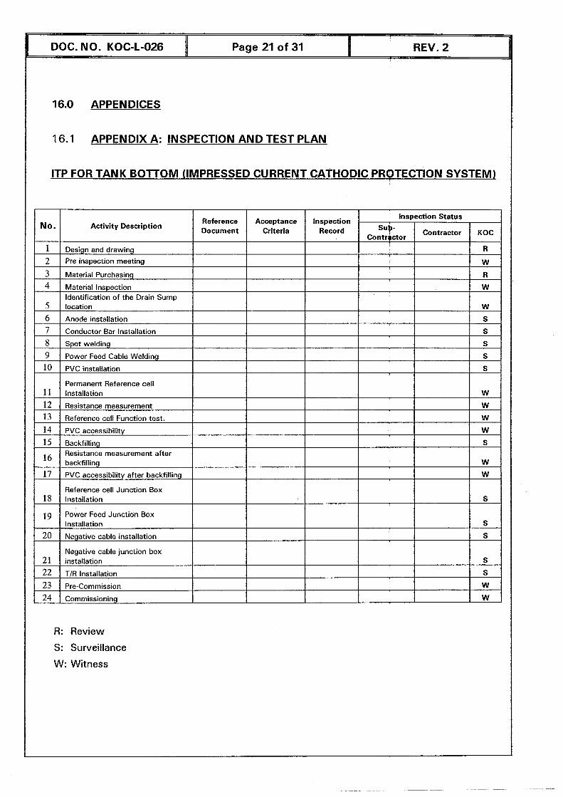
16.1 APPENDIX A: INSPECTION AND TEST PLAN
ITP FOR TANK BOTTOM (IMPRESSED CURRENT CATHODIC PROTECTION SYSTEM]
No. I Activity Description
1 Design and drawing
'2 Pre insoection meetina
3 Material Purchasing
4 Material Inspection Identification of the Drain Sump
5 location
6 Anode installation
7 Conductor Bar Installation
8 Spot welding
9 Power Feed Cable Welding
10 PVC installation
Permanent Reference cell 11 installation
12 Resistance measurement
13 Reference cell Function test.
14 PVC accessibility
15 Backfilling
16 Resistance measurement after backfilling
17 PVC accessibility after backfilling
Reference cell Junction Box 18 lnsta~~ation
19 Power feed Junction Box lnstallation
20 Negative cable installation
Negative cable junction box 21 installation
22 TIR Installation
23 re-Commission
24 Commissioning
R: Review
S: Surveillance
W: Witness
Inspection Status Reference Acceptance Inspection Document Criteria Record Contractor KOC sug-
Contrqctor
I R
DOC. NO. KOC-L-026 I Page 22 of 31 I REV. 2
16.2 APPENDIX B : iNSPECTION & TEST SHEETS AND CHECK LISTS
1.0 Tank Bottom Cathodic Protection System (Grid System)
2.0 Reference Electrode Function Test
3.0 Boxes (J.B and Test Box)
4.0 TR / Rectifier Check List
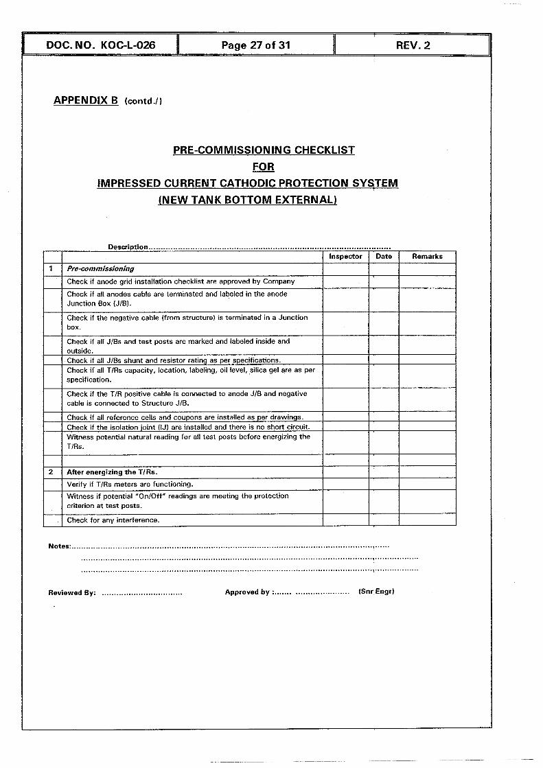
5.0 Pre-commissioning Checklist for Impressed Current Cathodic Protection
System (New Tank Bottom External)
6.0 Tank Bottom CP Summary Data Sheet
1 6.3 APPENDIX C : DRAWING NO. CP-002
Typical Cathodic Protection Details for Ungerside of Tank Bottom Using Grid System.
APPENDIX B (contd.1)
DOC. NO. KOC-L-026
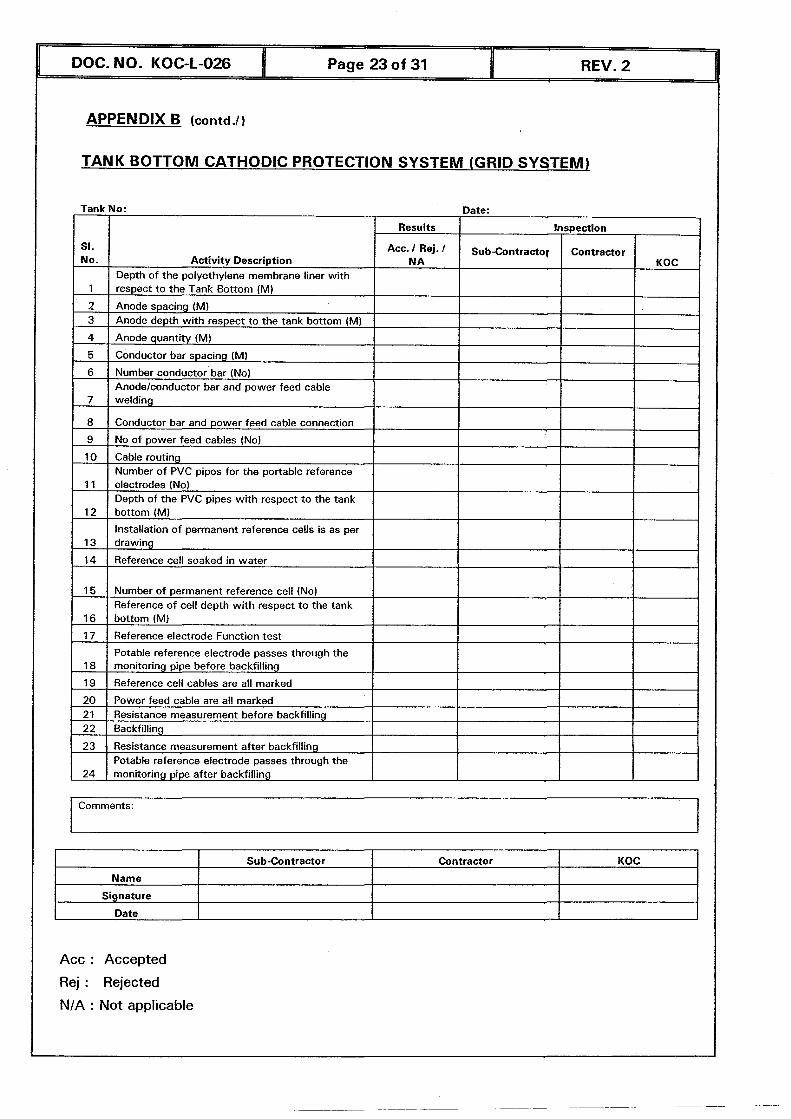
TANK BOTTOM CATHODIC PROTECTION SYSTEM (GRID SYSTEM)
Page 23 of 31 I REV. 2
Tank No: Date:
2 1 Anode spacing (M) I I 1 3 1 Anode depth with respect to the tank bottom (M) I 1 I
I St. No.
1
Results
Activity Description Depth of the polyethylene membrane liner with respect to the Tank Bottom (M)
4
5
6
10 ] Cable routing I 1 I I 1 Number of PVC pipes for the portable reference I
Inspection
Anode quantity (M)
Conductor bar spacing (M)
Number conductor bar (No)
7
8
9
11 I electrodes (No) I I I 1 / Depth of the PVC pipes with respect to the tank 1
I I I
Act- I 1 N A
welding
Conductor bar and power feed cable connection
No of power feed cables (No)
1 Anode/conductor bar and power feed cable
Sub-Contractor
I
12
13
14
20 1 Power feed cable are all marked 1 I 1 I 21 1 Resistance measurement before backfilling
bottom (M)
Installation of permanent reference cells is as per drawing
Reference cell soaked in water
15
16
17
18
19
22 1 Backfilling 1 1 1
Contractor KOC
Number of permanent reference cell (No) Reference of cell depth with respect to the tank bottom (M)
Reference electrode Function test
Potable reference electrode passes through the monitoring pipe before backfilling
Reference cell cables are all marked t
Comments:
I I
23
24
1 Sub-Contractor ! Contractor 1 KOC I
Resistance measurement after backfilling Potable reference electrode passes through the monitoring pipe after backfilling
Name 1 Signature
Date
Acc : Accepted
Rej : Rejected
NIA : Not applicable
APPENDIX B (contd.1)
Tank No:
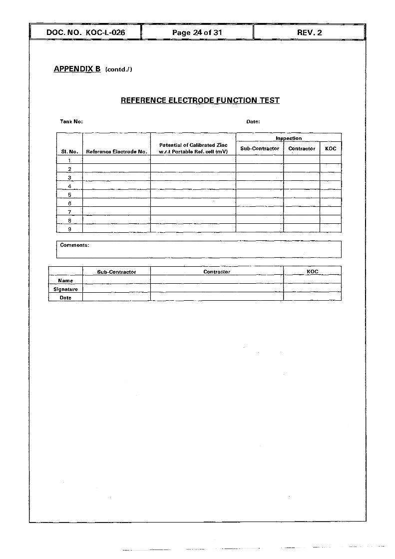
REFERENCE ELECTRODE FUNCTION TEST
Date:
lnppection Potential of Calibrated Zinc
SI. No. Reference Electrode No. w.r+ Portable Ref. cell (mV) Sub-Contractor Contractor KOC
1
2
3
4
5
6
7 R I
Comments:
1 Sub-Contractor Contractor KOC Name
Signature
Date
DOC. NO. KOC-1-026 I Page 25 of 31 I REV. 2
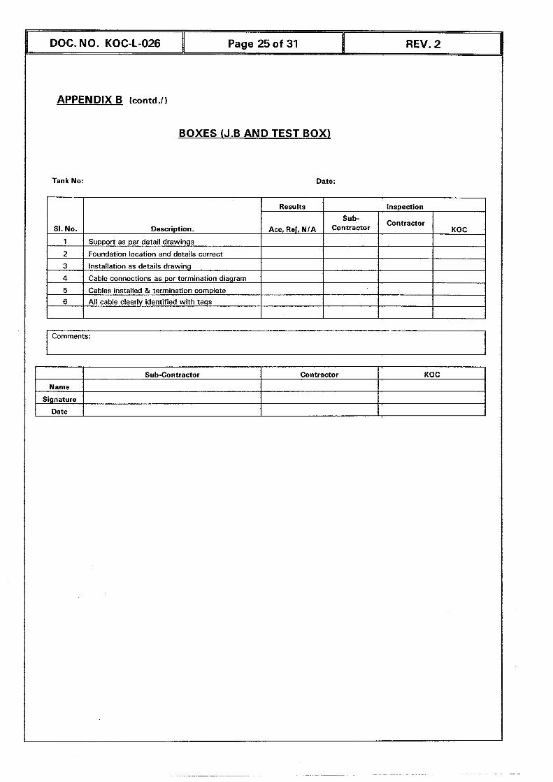
BOXES (J.B AND TEST BOX)
Tank No: Date:
1 Comments: I
SI. No.
1
2
3
Signature
Date 1 1
Description.
Support as per detail drawings
Foundation location and details correct
Installation as details drawing
4
5 6
KOC Sub-contractor
Results
Acc. Rej, N /A
Cable connections as per termination diagram
Cables installed & termination complete
All cable clearly identified with tags
Contractor
1 I 1 I 1 I
Inspection
Sub- contractor Contractor
KOC
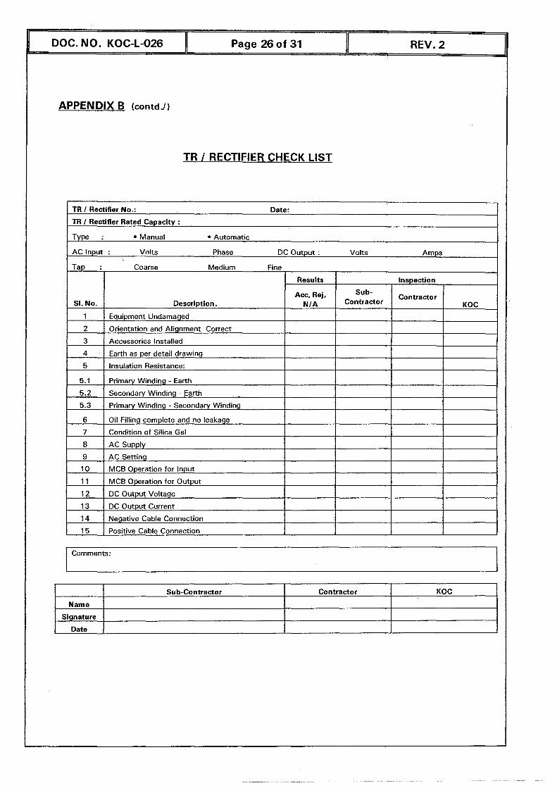
APPENDIX B (contd J )
DOC. NO. KOC-L-026
TR 1 RECTIFIER CHECK LIST
Page 26 of 31 REV. 2
TR I Rectifier No.: Date:
TR I Rectifier Rated Capacity :
Type : Manual Automatic
I Comments:
AC Input : Volts Phase DC Output : Volts Amps
Tap :
SI. No.
1
2
3
4
5
5.1
5.2
5.3
6
7
8
9
Coarse Medium Fine
Description.
Equipment Undamaged
Orientation and Alignment Correct
Accessories Installed
Earth as per detail drawing
Insulation Resistance:
Primary Winding - Earth
Secondary Windrng - Earth
Primary Winding - Secondary Winding
Oil Filling complete and no leakage
Condition of Silica Gel
AC Supply
AC Setting
Name
Signature
Contractor Sub-Contractor
Results
Acc, Rej, NI A
KOC
Sub- contractor
Inspection
Contractor KOC
DOC. NO. KOC-L-026 Page 27 of 31 REV. 2
APPENDIX B (contd.!)
PRE-COMMISSIONING CHECKLIST
FOR
IMPRESSED CURRENT CATHODIC PROTECTION SYSTEM
JNEW TANK BOTTOM EXTERNAL)
................................................................................................... Description
I I I Inspector I Date ( Remarks ]
Check if the negative cable (from structure) is terminated in a Junction box.
Check if all JIBS and test posts are marked and labeled inside and
1
I outside. I 1 Check if all JIBS shunt and resistor rating as per specifications.
Check i f all TiRs capacity, location, labeling, oil level,,silica gel are as per specification.
Check i f the TlR positive cable is connected to anode JIB and negative cable is connected to Structure JIB.
Pre-commissioning
Check i f anode grid installation checklist are approved by Company
Check i f all anodes cable are terminated and labeled in the anode Junction Box (JIB).
I Check i f all reference cells and coupons are installed as per drawings. 1 Check i f the isolation joint (IJ) are installed and there is no short circuit. I
I
Witness potential natural reading for all test posts before energizing the TIRs.
2
...... ......................................................................................................................... Notes:
..........................................................................................................................................
...........................................................................................
criterion at test posts.
Check for any interference. 1
............................. Reviewed By: ................................. Approved by : (Snr Engrl
After energizing the TIRs.
Verify if TlRs meters are functioning.
Witness i f potential "OnJOff" readings are meeting the protection
I
1
1
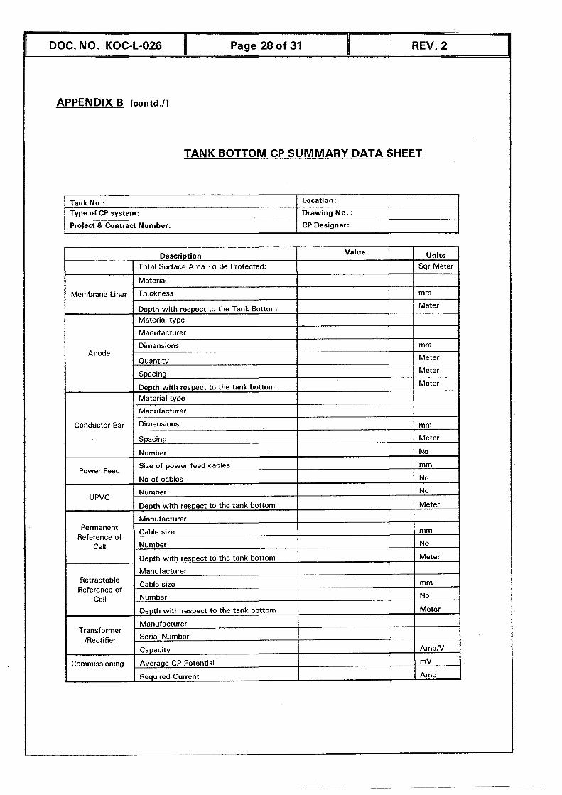
APPENDIX B Icontd.1)
TANK BOTTOM CP SUMMARY DATA SHEET
Tank No.: Type of CP system:
Project & Contract Number:
Location:
Drawing No. :
CP Designer:
I Description
1
Material
Membrane Liner Thickness mm
Depth with respect to the Tank Bottom I
I Anode I I
Quantity Meter I
I Total Surface Area To Be Protected: I I Sqr Meter
Value
- Meter
1
Manufacturer
Dimensions
I Spacing I Meter I
Units
I Material type I I mm
DOC. NO. KOC-L-026
I Spacing 1 Meter I I
Page 28 of 31 I REV. 2
Conductor Bar
Power Feed
-
UPVC
Permanent Reference of
Cell - I
I Retractable Reference of
Cell
1 Transformer /Rectifier
Depth with respect to the tank bottom Material type
Manufacturer
Dimensions
1 Commissioning
Meter
mm
Size of power feed cables mm
No of cables No
Number No
Depth with respect to the tank bottom Meter
Manufacturer
Cable size mm
Number No
Depth with respect to the tank bottom Meter
Manufacturer
Cable size mm
Number No
Depth with respect to the tank bottom Meter
Manufacturer
Serial Number
Capacity AmpN
Average CP Potential , mV I
1 ] Required Current I 1 Amp I
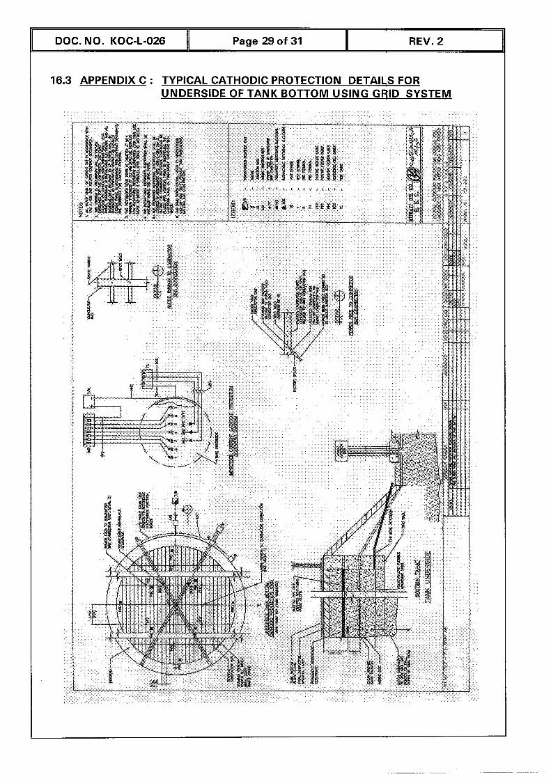
I DOC. NO. KOC-L-026 11 Page 29 of 31 11 REV. 2 11
16.3 APPENDIX C : TYPICAL CATHODIC PROTECTION DETAILS FOR UNDERSIDE OF TANK BOTTOM USING GRID SYSTEM
ENGINEERING GROUP
Team Leader Design
AHMADI SERVICES GROUP
Team Leader Utilities Team Leader Project Design
OPERATIONS GROUP (SK)
Team Leader Opns. Tech. Svcs.
OPERATIONS GROUP (EK)
Team Leader Opns. Tech. Svcs
EXPORT & MARINE OPNS GROUP
Team Leader Export SVGS
MAINTENANCE GROUP (EK)
Team Leader Maintenance
HSE GROUP (SEK)
Team Leader HSE (SEK)
MAJOR PROJECTS GROUP (I)
Team Leader Export Fqc. Projects.
HSE GROUP
Team Leader Safety Team Leader HSE Systems Team Leader H&E
OPERATIONS GROUP. (WK)
Team Leader Opns. Tech. Svcs
OPERATIONS GROUP.(NK)
Team Leader Opns. Tech. Svcs.
DRILLING OPNS GROUP
Team Leader Drilling & WlOver Svcs.
SUPPORT SVCS. GROUP ISEK)
Team Leader General Rrojects
ACKNOWLEDGEMENT
This Standard has been approved by the Standards Technical Committee (STC) consisting of the following:
Mr. A/Redha Al-Haddad Standards Team Mr. Mohammad Emam Insp. & Corr. Team (S&E) Mr. S. Kumar Standards Team Mr. Henry Hill Opns. Tech. Svcs. Team (SK Mr. A. Unnikrishnan Standards Team Mr. Khalaf Hamada Design Team Mr. N. Ramanathan Export Facilities Team Mr. Ali Hassan Al-Failakawi HSE System Team Mr. Daniel Pino Utilities Team Mr. Abdul R. Al-Shamari Insp. & Corr. Team (N&WK) Mr. Khalid Al-Ahmad Gen. Project Team Mr. Abdul Aziz Akbar Project Mgmt. Team (NK) Mr. Moataz Khalaf Information System Team
Chairman Deputy Chairman Secretary1 Member
) Merqber Merqber Merqber Meqber Menqber Merrjber Meqber Merriber ~ e 4 b e r Meriber
The draft of this Standard had been circulated to the KOC User Teams for review and the responses were received from the following:
DOC. NO. KOC-L-026 I Page 30 of 31 I REV. 2
-
DOC. NO. KOC-L-026 I Page 31 of 31 I REV. 2
Task Force Res~onsible for this Recommended Practice
The Preparation of this Recommended Practice has been entrusted by the Standards Technical Committee (STC) of the Task Force No (TF-CPl02) Comprising of the following members:
Mr. Abdul Razzaq A1 Shamari Insp.& Corr. (NWK Mr. Hasan Sabri Insp. & Corr.(SEK) Mr. Govinda Mishra Design Team Mr. Liakat Ali Maintenance (WK) Mr. Uppara Saibaba HSE Systems
) TF Leader Tel No. 61 426 Member Tel No 67489 Member Tel No 61 097 Member Tel No 20061 Member Tel No 71 837
Recommended