Kelvion KEC Commercial air cooler
HIGH EFFICIENCY,HIGH PERFORMANCE

Welcome to Kelvion. Heat exchange is our business. Worldwide.
As a market leader in the technology sector, we have been
producing heat exchangers for virtually every conceivable
industrial application since the 1920s, including tailor-made
solutions suited for the most complex environmental conditions
– as of 2015 under the name of Kelvion.
With one of the most comprehensive ranges of heat exchangers
in the world, which includes compact finned-tube heat exchangers,
plate heat exchangers, single tube heat exchangers, shell and
tube heat exchangers, transformer cooling systems and wet
cooling towers, we are a sought after partner in a wide variety
of industries, such as: the energy industry, the oil and gas industry,
the chemical industry, the shipbuilding sector, the food and beverage
industry, the heavy industry, the sugar industry, the transport
sector, as well as building and refrigeration technology.
Many years of experience and in-depth expert knowledge make
us specialists in this field.
Our heat exchangers are designed for the requirements of the
respective process, thereby ensuring optimum energy efficiency
and reliability for all market segments. This provides our customers
with a technological advantage that reduces operating costs
and has a lasting effect.
A reliable after-sales service is essential with regard to customer
loyalty and retention. We have a worldwide service network
at our disposal. Our engineers are thereby able to carry out
maintenance work and complete repairs on-site at a customer’s
premises. This prevents unnecessary downtime – because we
are highly committed to earning your trust.
Kelvion – Experts in Heat Exchange.
EXPERTS IN HEAT EXCHANGE – SINCE 1920

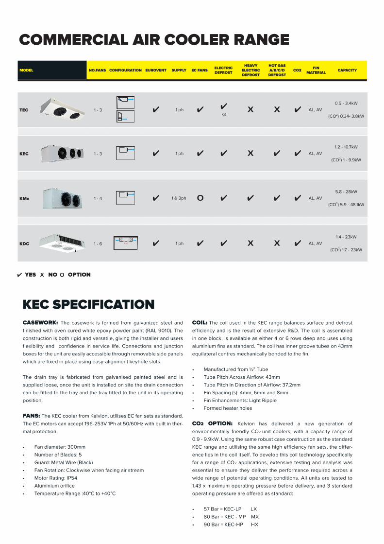
CASEWORK: The casework is formed from galvanized steel and
finished with oven cured white epoxy powder paint (RAL 9010). The
construction is both rigid and versatile, giving the installer and users
flexibility and confidence in service life. Connections and junction
boxes for the unit are easily accessible through removable side panels
which are fixed in place using easy-alignment keyhole slots.
The drain tray is fabricated from galvanised painted steel and is
supplied loose, once the unit is installed on site the drain connection
can be fitted to the tray and the tray fitted to the unit in its operating
position.
FANS: The KEC cooler from Kelvion, utilises EC fan sets as standard.
The EC motors can accept 196-253V 1Ph at 50/60Hz with built in ther-
mal protection.
• Fan diameter: 300mm
• Number of Blades: 5
• Guard: Metal Wire (Black)
• Fan Rotation: Clockwise when facing air stream
• Motor Rating: IP54
• Aluminium orifice
• Temperature Range :40°C to +40°C
COIL: The coil used in the KEC range balances surface and defrost
efficiency and is the result of extensive R&D. The coil is assembled
in one block, is available as either 4 or 6 rows deep and uses using
aluminium fins as standard. The coil has inner groove tubes on 43mm
equilateral centres mechanically bonded to the fin.
• Manufactured from ½” Tube
• Tube Pitch Across Airflow: 43mm
• Tube Pitch In Direction of Airflow: 37.2mm
• Fin Spacing (s): 4mm, 6mm and 8mm
• Fin Enhancements: Light Ripple
• Formed heater holes
CO2 OPTION: Kelvion has delivered a new generation of
environmentally friendly CO2 unit coolers, with a capacity range of
0.9 - 9.9kW. Using the same robust case construction as the standard
KEC range and utilising the same high efficiency fan sets, the differ-
ence lies in the coil itself. To develop this coil technology specifically
for a range of CO2 applications, extensive testing and analysis was
essential to ensure they deliver the performance required across a
wide range of potential operating conditions. All units are tested to
1.43 x maximum operating pressure before delivery, and 3 standard
operating pressure are offered as standard:
• 57 Bar = KEC-LP LX
• 80 Bar = KEC - MP MX
• 90 Bar = KEC-HP HX
COMMERCIAL AIR COOLER RANGE
MODEL NO.FANS CONFIGURATION EUROVENT SUPPLY EC FANS ELECTRICDEFROST
HEAVY ELECTRIC DEFROST
HOT GAS A/B/C/D
DEFROSTCO2 FIN
MATERIAL CAPACITY
KEC SPECIFICATION
YES NO OPTION
TEC 1 - 3 1 phkit
AL, AV0.5 - 3.4kW
(CO2) 0.34- 3.8kW
KEC 1 - 3 1 ph AL, AV1.2 - 10.7kW
(CO2) 1 - 9.9kW
KMe 1 - 4 1 & 3ph AL, AV5.8 - 28kW
(CO2) 5.9 - 48.1kW
KDC 1 - 6 1 ph AL, AV1.4 - 23kW
(CO2) 1.7 - 23kW
CAPACITY RANGEAPPLICATION & BENEFITS
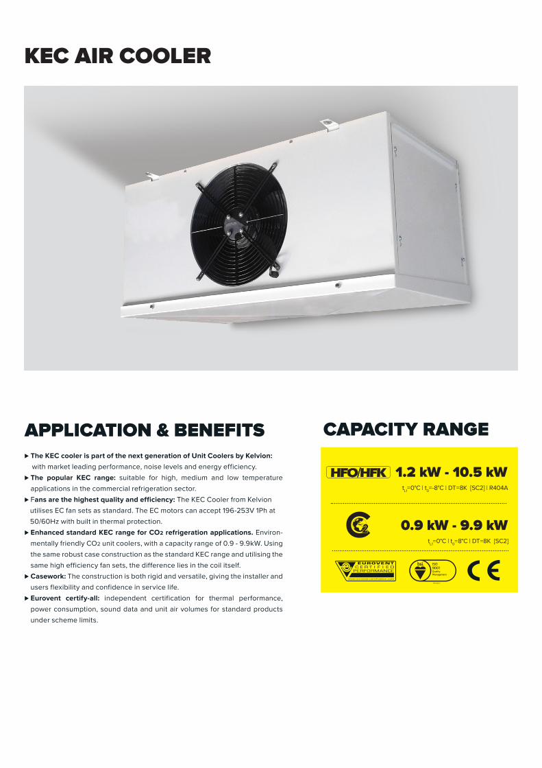
KEC AIR COOLER
⊲The KEC cooler is part of the next generation of Unit Coolers by Kelvion:
with market leading performance, noise levels and energy efficiency.
⊲The popular KEC range: suitable for high, medium and low temperature
applications in the commercial refrigeration sector.
⊲Fans are the highest quality and efficiency: The KEC Cooler from Kelvion
utilises EC fan sets as standard. The EC motors can accept 196-253V 1Ph at
50/60Hz with built in thermal protection.
⊲Enhanced standard KEC range for CO2 refrigeration applications. Environ-
mentally friendly CO2 unit coolers, with a capacity range of 0.9 - 9.9kW. Using
the same robust case construction as the standard KEC range and utilising the
same high efficiency fan sets, the difference lies in the coil itself.
⊲ Casework: The construction is both rigid and versatile, giving the installer and
users flexibility and confidence in service life.
⊲Eurovent certify-all: independent certification for thermal performance,
power consumption, sound data and unit air volumes for standard products
under scheme limits.
1.2 kW - 10.5 kWtL1= 0°C|t0= -8°C|DT = 8K[SC2]|R404A
0.9 kW - 9.9 kWtL1= 0°C|t0= 8°C|DT =8K[SC2]
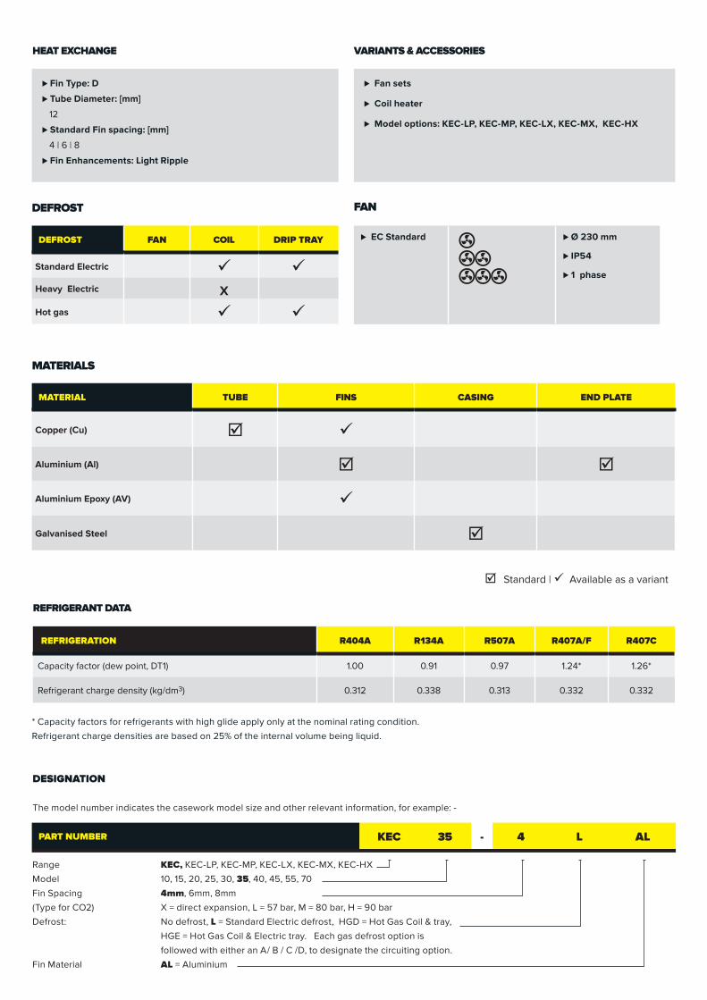
Range KEC, KEC-LP, KEC-MP, KEC-LX, KEC-MX, KEC-HX
Model 10, 15, 20, 25, 30, 35, 40, 45, 55, 70
Fin Spacing 4mm, 6mm, 8mm
(Type for CO2) X = direct expansion, L = 57 bar, M = 80 bar, H = 90 bar
Defrost: No defrost, L = Standard Electric defrost, HGD = Hot Gas Coil & tray,
HGE = Hot Gas Coil & Electric tray. Each gas defrost option is
followed with either an A/ B / C /D, to designate the circuiting option.
Fin Material AL = Aluminium
REFRIGERATION R404A R134A R507A R407A/F R407C
Capacity factor (dew point, DT1) 1.00 0.91 0.97 1.24* 1.26*
Refrigerant charge density (kg/dm3) 0.312 0.338 0.313 0.332 0.332
REFRIGERANT DATA
* Capacity factors for refrigerants with high glide apply only at the nominal rating condition.
Refrigerant charge densities are based on 25% of the internal volume being liquid.
MATERIAL TUBE FINS CASING END PLATE
Copper (Cu) þ ü
Aluminium (Al) þ þ
Aluminium Epoxy (AV) ü
Galvanised Steel þ
⊲Fin Type: D
⊲Tube Diameter: [mm]
12
⊲Standard Fin spacing: [mm]
4|6|8
⊲Fin Enhancements: Light Ripple
MATERIALS
⊲ Fan sets
⊲ Coil heater
⊲Model options: KEC-LP, KEC-MP, KEC-LX, KEC-MX, KEC-HX
DEFROST FAN COIL DRIP TRAY
Standard Electric ü üHeavy Electric X
Hot gas ü ü
þ Standard|ü Available as a variant
HEAT EXCHANGE VARIANTS & ACCESSORIES
DEFROST FAN
DESIGNATION
The model number indicates the casework model size and other relevant information, for example: -
PART NUMBER KEC 35 - 4 L AL
⊲ EC Standard ⊲ Ø 230 mm
⊲ IP54
⊲ 1 phase

SELECTION DATA
FIN SPACING MODEL
CAPACITY 8K DT1 R404A
*
MOTOR DETAILS 230V - 1PH - 50Hz FAN DATA CONNECTION
INTER-NAL
VOLUME
SURFACE AREA
REF CHARGE WEIGHT
NO. OF
FANS
POWER INPUT
FLC PER FAN
SC PER FAN
SPEED AIR VOLUME
AIR THROW
***
NOISE LEVEL @ 3M
**INLET OUTLET
kW W Amps Amps RPM m3/s m dB(A) dm3 m2 kg kg
4mm
KEC10-4 1.65 1 33 0.35 0.50 1370 0.28 16.0 44 1/2“ 1/2“ 1.4 8.5 0.5 27
KEC15-4 2.01 1 33 0.35 0.50 1370 0.28 16.0 44 1/2“ 1/2“ 1.9 10.0 0.6 28
KEC20-4 2.35 1 33 0.35 0.50 1370 0.29 16.0 44 1/2“ 5/8“ 2.5 13.7 0.8 33
KEC25-4 3.00 1 77 0.70 1.00 1750 0.42 22.0 52 1/2“ 5/8“ 2.5 13.7 0.8 33
KEC30-4 3.73 1 77 0.70 1.00 1750 0.40 22.0 52 1/2“ 7/8“ 3.8 20.5 1.2 35
KEC35-4 4.57 2 66 0.35 0.50 1370 0.58 16.0 47 1/2“ 7/8“ 4.3 24.9 1.4 47
KEC40-4 5.84 2 154 0.70 1.00 1750 0.83 22.0 55 1/2“ 7/8“ 4.3 24.9 1.4 47
KEC45-4 6.99 2 154 0.70 1.00 1750 0.81 22.0 55 1/2“ 7/8“ 6.5 37.4 2.1 53
KEC55-4 8.79 3 231 0.70 1.00 1750 1.25 22.0 57 1/2“ 7/8“ 6.3 37.4 2.0 67
KEC70-4 10.51 3 231 0.70 1.00 1750 1.21 22.0 57 5/8“ 7/8“ 9.4 56.0 3.0 74
6mm
KEC10-6 1.34 1 33 0.35 0.50 1370 0.31 16.0 44 1/2“ 1/2“ 1.4 5.8 0.5 27
KEC15-6 1.72 1 33 0.35 0.50 1370 0.31 16.0 44 1/2“ 1/2“ 1.9 6.8 0.6 28
KEC20-6 1.99 1 33 0.35 0.50 1370 0.32 16.0 44 1/2“ 5/8“ 2.5 9.4 0.8 33
KEC25-6 2.38 1 77 0.70 1.00 1750 0.43 22.0 52 1/2“ 5/8“ 2.5 9.4 0.8 33
KEC30-6 3.16 1 77 0.70 1.00 1750 0.42 22.0 52 1/2“ 7/8“ 3.8 14.1 1.2 35
KEC35-6 3.85 2 66 0.35 0.50 1370 0.63 16.0 47 1/2“ 7/8“ 4.3 17.0 1.4 47
KEC40-6 4.63 2 154 0.70 1.00 1750 0.85 22.0 55 1/2“ 7/8“ 4.3 17.0 1.4 47
KEC45-6 5.97 2 154 0.70 1.00 1750 0.83 22.0 55 1/2“ 7/8“ 6.5 25.6 2.1 53
KEC55-6 7.00 3 231 0.70 1.00 1750 1.28 22.0 57 1/2“ 7/8“ 6.3 25.6 2.0 67
KEC70-6 8.98 3 231 0.70 1.00 1750 1.25 22.0 57 5/8“ 7/8“ 9.4 38.3 3.0 74
8mm
KEC10-8 1.17 1 33 0.35 0.50 1370 0.32 16.0 44 1/2“ 1/2“ 1.4 4.4 0.5 27
KEC15-8 1.52 1 33 0.35 0.50 1370 0.32 16.0 44 1/2“ 1/2“ 1.9 5.2 0.6 28
KEC20-8 1.74 1 33 0.35 0.50 1370 0.33 16.0 44 1/2“ 5/8“ 2.5 7.2 0.8 33
KEC25-8 2.06 1 77 0.70 1.00 1750 0.44 22.0 52 1/2“ 5/8“ 2.5 7.2 0.8 33
KEC30-8 2.75 1 77 0.70 1.00 1750 0.43 22.0 52 1/2“ 7/8“ 3.8 10.8 1.2 35
KEC35-8 3.30 2 66 0.35 0.50 1370 0.65 16.0 47 1/2“ 7/8“ 4.3 13.1 1.4 47
KEC40-8 3.98 2 154 0.70 1.00 1750 0.86 22.0 55 1/2“ 7/8“ 4.3 13.1 1.4 47
KEC45-8 5.31 2 154 0.70 1.00 1750 0.86 22.0 55 1/2“ 7/8“ 6.5 19.7 2.1 53
KEC55-8 6.01 3 231 0.70 1.00 1750 1.31 22.0 57 1/2“ 7/8“ 6.3 19.7 2.0 67
KEC70-8 7.97 3 231 0.70 1.00 1750 1.29 22.0 57 5/8“ 7/8“ 9.4 29.5 3.0 74
NOTES: Rating conditions: The duties shown in this brochure are at EN 328 Standard Condition 2 (-8°C saturated suction temperature, 0°C air entering).For data on refrigerants not shown, please contact your supplier.
• * DT1isthedifferencebetweentheenteringairtemperatureandthesaturatedsuctiontemperatureattheoutletofthecooler.• ** Noiselevelsarebasedonfreefieldconditionsatadistanceof3m.Actualnoiselevelswilldependuponcoldstoreconstruction,storeloading and the number of coolers installed.• *** Terminal air velocity 0.25m/s, free air conditions at 10°C. Air throw cannot be considered an absolute value because many factors have a
substantialeffectonthedistanceachieved.
MODEL
230V-1PH-50/60HZ STANDARD
Coil Pan Total
kW W kW
KEC10-* 0.68 0.34 1.02
KEC15-* 0.68 0.34 1.02
KEC20-* 0.92 0.46 1.38
KEC25-* 0.92 0.46 1.38
KEC25-* 0.92 0.46 1.38
KEC35-* 1.6 0.8 2.4
KEC40-* 1.6 0.8 2.4
KEC45-* 1.6 0.8 2.4
KEC55-* 2.4 1.2 3.6
KEC70-* 2.4 1.2 3.6
ELECTRIC DEFROST DATA
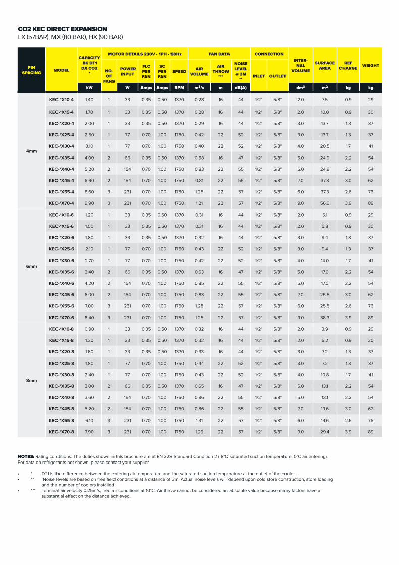
CO2 KEC DIRECT EXPANSIONLX(57BAR),MX(80BAR),HX(90BAR)
FIN SPACING MODEL
CAPACITY 8K DT1 DX CO2
*
MOTOR DETAILS 230V - 1PH - 50Hz FAN DATA CONNECTIONINTER-
NAL VOLUME
SURFACE AREA
REF CHARGE WEIGHT
NO. OF
FANS
POWER INPUT
FLC PER FAN
SC PER FAN
SPEED AIR VOLUME
AIR THROW
***
NOISE LEVEL @ 3M
**INLET OUTLET
kW W Amps Amps RPM m3/s m dB(A) dm3 m2 kg kg
4mm
KEC-*X10-4 1.40 1 33 0.35 0.50 1370 0.28 16 44 1/2" 5/8" 2.0 7.5 0.9 29
KEC-*X15-4 1.70 1 33 0.35 0.50 1370 0.28 16 44 1/2" 5/8" 2.0 10.0 0.9 30
KEC-*X20-4 2.00 1 33 0.35 0.50 1370 0.29 16 44 1/2" 5/8" 3.0 13.7 1.3 37
KEC-*X25-4 2.50 1 77 0.70 1.00 1750 0.42 22 52 1/2" 5/8" 3.0 13.7 1.3 37
KEC-*X30-4 3.10 1 77 0.70 1.00 1750 0.40 22 52 1/2" 5/8" 4.0 20.5 1.7 41
KEC-*X35-4 4.00 2 66 0.35 0.50 1370 0.58 16 47 1/2" 5/8" 5.0 24.9 2.2 54
KEC-*X40-4 5.20 2 154 0.70 1.00 1750 0.83 22 55 1/2" 5/8" 5.0 24.9 2.2 54
KEC-*X45-4 6.90 2 154 0.70 1.00 1750 0.81 22 55 1/2" 5/8" 7.0 37.3 3.0 62
KEC-*X55-4 8.60 3 231 0.70 1.00 1750 1.25 22 57 1/2" 5/8" 6.0 37.3 2.6 76
KEC-*X70-4 9.90 3 231 0.70 1.00 1750 1.21 22 57 1/2" 5/8" 9.0 56.0 3.9 89
6mm
KEC-*X10-6 1.20 1 33 0.35 0.50 1370 0.31 16 44 1/2" 5/8" 2.0 5.1 0.9 29
KEC-*X15-6 1.50 1 33 0.35 0.50 1370 0.31 16 44 1/2" 5/8" 2.0 6.8 0.9 30
KEC-*X20-6 1.80 1 33 0.35 0.50 1370 0.32 16 44 1/2" 5/8" 3.0 9.4 1.3 37
KEC-*X25-6 2.10 1 77 0.70 1.00 1750 0.43 22 52 1/2" 5/8" 3.0 9.4 1.3 37
KEC-*X30-6 2.70 1 77 0.70 1.00 1750 0.42 22 52 1/2" 5/8" 4.0 14.0 1.7 41
KEC-*X35-6 3.40 2 66 0.35 0.50 1370 0.63 16 47 1/2" 5/8" 5.0 17.0 2.2 54
KEC-*X40-6 4.20 2 154 0.70 1.00 1750 0.85 22 55 1/2" 5/8" 5.0 17.0 2.2 54
KEC-*X45-6 6.00 2 154 0.70 1.00 1750 0.83 22 55 1/2" 5/8" 7.0 25.5 3.0 62
KEC-*X55-6 7.00 3 231 0.70 1.00 1750 1.28 22 57 1/2" 5/8" 6.0 25.5 2.6 76
KEC-*X70-6 8.40 3 231 0.70 1.00 1750 1.25 22 57 1/2" 5/8" 9.0 38.3 3.9 89
8mm
KEC-*X10-8 0.90 1 33 0.35 0.50 1370 0.32 16 44 1/2" 5/8" 2.0 3.9 0.9 29
KEC-*X15-8 1.30 1 33 0.35 0.50 1370 0.32 16 44 1/2" 5/8" 2.0 5.2 0.9 30
KEC-*X20-8 1.60 1 33 0.35 0.50 1370 0.33 16 44 1/2" 5/8" 3.0 7.2 1.3 37
KEC-*X25-8 1.80 1 77 0.70 1.00 1750 0.44 22 52 1/2" 5/8" 3.0 7.2 1.3 37
KEC-*X30-8 2.40 1 77 0.70 1.00 1750 0.43 22 52 1/2" 5/8" 4.0 10.8 1.7 41
KEC-*X35-8 3.00 2 66 0.35 0.50 1370 0.65 16 47 1/2" 5/8" 5.0 13.1 2.2 54
KEC-*X40-8 3.60 2 154 0.70 1.00 1750 0.86 22 55 1/2" 5/8" 5.0 13.1 2.2 54
KEC-*X45-8 5.20 2 154 0.70 1.00 1750 0.86 22 55 1/2" 5/8" 7.0 19.6 3.0 62
KEC-*X55-8 6.10 3 231 0.70 1.00 1750 1.31 22 57 1/2" 5/8" 6.0 19.6 2.6 76
KEC-*X70-8 7.90 3 231 0.70 1.00 1750 1.29 22 57 1/2" 5/8" 9.0 29.4 3.9 89
NOTES: Rating conditions: The duties shown in this brochure are at EN 328 Standard Condition 2 (-8°C saturated suction temperature, 0°C air entering).For data on refrigerants not shown, please contact your supplier.
• * DT1isthedifferencebetweentheenteringairtemperatureandthesaturatedsuctiontemperatureattheoutletofthecooler.• ** Noiselevelsarebasedonfreefieldconditionsatadistanceof3m.Actualnoiselevelswilldependuponcoldstoreconstruction,storeloading and the number of coolers installed.• *** Terminal air velocity 0.25m/s, free air conditions at 10°C. Air throw cannot be considered an absolute value because many factors have a
substantialeffectonthedistanceachieved.
FIN SPACING MODEL
CAPACITY 8K DT1 DX CO2
*
MOTOR DETAILS 230V - 1PH - 50Hz FAN DATA CONNECTIONINTER-
NAL VOLUME
SURFACE AREA
REF CHARGE WEIGHT
NO. OF
FANS
POWER INPUT
FLC PER FAN
SC PER FAN
SPEED AIR VOLUME
AIR THROW
***
NOISE LEVEL @ 3M
**INLET OUTLET
kW W Amps Amps RPM m3/s m dB(A) dm3 m2 kg kg
4mm
KEC-*X10-4 1.40 1 33 0.35 0.50 1370 0.28 16 44 1/2" 5/8" 2.0 7.5 0.9 29
KEC-*X15-4 1.70 1 33 0.35 0.50 1370 0.28 16 44 1/2" 5/8" 2.0 10.0 0.9 30
KEC-*X20-4 2.00 1 33 0.35 0.50 1370 0.29 16 44 1/2" 5/8" 3.0 13.7 1.3 37
KEC-*X25-4 2.50 1 77 0.70 1.00 1750 0.42 22 52 1/2" 5/8" 3.0 13.7 1.3 37
KEC-*X30-4 3.10 1 77 0.70 1.00 1750 0.40 22 52 1/2" 5/8" 4.0 20.5 1.7 41
KEC-*X35-4 4.00 2 66 0.35 0.50 1370 0.58 16 47 1/2" 5/8" 5.0 24.9 2.2 54
KEC-*X40-4 5.20 2 154 0.70 1.00 1750 0.83 22 55 1/2" 5/8" 5.0 24.9 2.2 54
KEC-*X45-4 6.90 2 154 0.70 1.00 1750 0.81 22 55 1/2" 5/8" 7.0 37.3 3.0 62
KEC-*X55-4 8.60 3 231 0.70 1.00 1750 1.25 22 57 1/2" 5/8" 6.0 37.3 2.6 76
KEC-*X70-4 9.90 3 231 0.70 1.00 1750 1.21 22 57 1/2" 5/8" 9.0 56.0 3.9 89
6mm
KEC-*X10-6 1.20 1 33 0.35 0.50 1370 0.31 16 44 1/2" 5/8" 2.0 5.1 0.9 29
KEC-*X15-6 1.50 1 33 0.35 0.50 1370 0.31 16 44 1/2" 5/8" 2.0 6.8 0.9 30
KEC-*X20-6 1.80 1 33 0.35 0.50 1370 0.32 16 44 1/2" 5/8" 3.0 9.4 1.3 37
KEC-*X25-6 2.10 1 77 0.70 1.00 1750 0.43 22 52 1/2" 5/8" 3.0 9.4 1.3 37
KEC-*X30-6 2.70 1 77 0.70 1.00 1750 0.42 22 52 1/2" 5/8" 4.0 14.0 1.7 41
KEC-*X35-6 3.40 2 66 0.35 0.50 1370 0.63 16 47 1/2" 5/8" 5.0 17.0 2.2 54
KEC-*X40-6 4.20 2 154 0.70 1.00 1750 0.85 22 55 1/2" 5/8" 5.0 17.0 2.2 54
KEC-*X45-6 6.00 2 154 0.70 1.00 1750 0.83 22 55 1/2" 5/8" 7.0 25.5 3.0 62
KEC-*X55-6 7.00 3 231 0.70 1.00 1750 1.28 22 57 1/2" 5/8" 6.0 25.5 2.6 76
KEC-*X70-6 8.40 3 231 0.70 1.00 1750 1.25 22 57 1/2" 5/8" 9.0 38.3 3.9 89
8mm
KEC-*X10-8 0.90 1 33 0.35 0.50 1370 0.32 16 44 1/2" 5/8" 2.0 3.9 0.9 29
KEC-*X15-8 1.30 1 33 0.35 0.50 1370 0.32 16 44 1/2" 5/8" 2.0 5.2 0.9 30
KEC-*X20-8 1.60 1 33 0.35 0.50 1370 0.33 16 44 1/2" 5/8" 3.0 7.2 1.3 37
KEC-*X25-8 1.80 1 77 0.70 1.00 1750 0.44 22 52 1/2" 5/8" 3.0 7.2 1.3 37
KEC-*X30-8 2.40 1 77 0.70 1.00 1750 0.43 22 52 1/2" 5/8" 4.0 10.8 1.7 41
KEC-*X35-8 3.00 2 66 0.35 0.50 1370 0.65 16 47 1/2" 5/8" 5.0 13.1 2.2 54
KEC-*X40-8 3.60 2 154 0.70 1.00 1750 0.86 22 55 1/2" 5/8" 5.0 13.1 2.2 54
KEC-*X45-8 5.20 2 154 0.70 1.00 1750 0.86 22 55 1/2" 5/8" 7.0 19.6 3.0 62
KEC-*X55-8 6.10 3 231 0.70 1.00 1750 1.31 22 57 1/2" 5/8" 6.0 19.6 2.6 76
KEC-*X70-8 7.90 3 231 0.70 1.00 1750 1.29 22 57 1/2" 5/8" 9.0 29.4 3.9 89
FIN SPACING MODEL
CAPACITY 8K DT1
PUMPED CO2
*
MOTOR DETAILS 230V - 1PH - 50Hz FAN DATA CONNECTION
INTER-NAL
VOLUME
SURFACE AREA
REF CHARGE WEIGHT
NO. OF
FANS
POWER INPUT
FLC PER FAN
SC PER FAN
SPEED AIR VOLUME
AIR THROW
***
NOISE LEVEL @ 3M
**INLET OUTLET
kW W Amps Amps RPM m3/s m dB(A) dm3 m2 kg kg
4mm
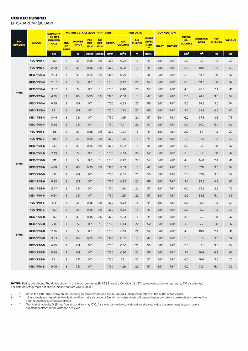
KEC-*P10-4 1.80 1 33 0.35 0.5 1370 0.28 16 44 5/8" 7/8" 2.0 7.5 1.2 29
KEC-*P15-4 2.09 1 33 0.35 0.5 1370 0.28 16 44 5/8" 7/8" 2.0 10.0 1.2 30
KEC-*P20-4 2.33 1 33 0.35 0.5 1370 0.29 16 44 5/8" 7/8" 3.0 13.7 1.8 37
KEC-*P25-4 2.97 1 77 0.7 1 1750 0.42 22 52 5/8" 7/8" 3.0 13.7 1.8 37
KEC-*P30-4 3.57 1 77 0.7 1 1750 0.40 22 52 5/8" 7/8" 4.0 20.5 2.4 41
KEC-*P35-4 4.70 2 66 0.35 0.5 1370 0.58 16 47 5/8" 7/8" 5.0 24.9 3.0 54
KEC-*P40-4 6.35 2 154 0.7 1 1750 0.83 22 55 5/8" 7/8" 5.0 24.9 3.0 54
KEC-*P45-4 7.91 2 154 0.7 1 1750 0.81 22 55 5/8" 7/8" 7.0 37.3 4.2 62
KEC-*P55-4 10.16 3 231 0.7 1 1750 1.25 22 57 5/8" 7/8" 6.0 37.3 3.6 76
KEC-*P70-4 11.36 3 231 0.7 1 1750 1.21 22 57 5/8" 7/8" 9.0 56.0 5.4 89
6mm
KEC-*P10-6 1.55 1 33 0.35 0.5 1370 0.31 16 44 5/8" 7/8" 2.0 5.1 1.2 29
KEC-*P15-6 1.85 1 33 0.35 0.5 1370 0.31 16 44 5/8" 7/8" 2.0 6.8 1.2 30
KEC-*P20-6 2.10 1 33 0.35 0.5 1370 0.32 16 44 5/8" 7/8" 3.0 9.4 1.8 37
KEC-*P25-6 2.49 1 77 0.7 1 1750 0.43 22 52 5/8" 7/8" 3.0 9.4 1.8 37
KEC-*P30-6 3.11 1 77 0.7 1 1750 0.42 22 52 5/8" 7/8" 4.0 14.0 2.4 41
KEC-*P35-6 4.00 2 66 0.35 0.5 1370 0.63 16 47 5/8" 7/8" 5.0 17.0 3.0 54
KEC-*P40-6 5.12 2 154 0.7 1 1750 0.85 22 55 5/8" 7/8" 5.0 17.0 3.0 54
KEC-*P45-6 6.88 2 154 0.7 1 1750 0.83 22 55 5/8" 7/8" 7.0 25.5 4.2 62
KEC-*P55-6 8.27 3 231 0.7 1 1750 1.28 22 57 5/8" 7/8" 6.0 25.5 3.6 76
KEC-*P70-6 9.64 3 231 0.7 1 1750 1.25 22 57 5/8" 7/8" 9.0 38.3 5.4 89
8mm
KEC-*P10-8 1.16 1 33 0.35 0.5 1370 0.32 16 44 5/8" 7/8" 2.0 3.9 1.2 29
KEC-*P15-8 1.60 1 33 0.35 0.5 1370 0.32 16 44 5/8" 7/8" 2.0 5.2 1.2 30
KEC-*P20-8 1.87 1 33 0.35 0.5 1370 0.33 16 44 5/8" 7/8" 3.0 7.2 1.8 37
KEC-*P25-8 2.14 1 77 0.7 1 1750 0.44 22 52 5/8" 7/8" 3.0 7.2 1.8 37
KEC-*P30-8 2.76 1 77 0.7 1 1750 0.43 22 52 5/8" 7/8" 4.0 10.8 2.4 41
KEC-*P35-8 3.53 2 66 0.35 0.5 1370 0.65 16 47 5/8" 7/8" 5.0 13.1 3.0 54
KEC-*P40-8 4.39 2 154 0.7 1 1750 0.86 22 55 5/8" 7/8" 5.0 13.1 3.0 54
KEC-*P45-8 5.96 2 154 0.7 1 1750 0.86 22 55 5/8" 7/8" 7.0 19.6 4.2 62
KEC-*P55-8 7.21 3 231 0.7 1 1750 1.31 22 57 5/8" 7/8" 6.0 19.6 3.6 76
KEC-*P70-8 9.06 3 231 0.7 1 1750 1.29 22 57 5/8" 7/8" 9.0 29.4 5.4 89
CO2 KEC PUMPEDLP(57BAR),MP(80BAR)
NOTES: Rating conditions: The duties shown in this brochure are at EN 328 Standard Condition 2 (-8°C saturated suction temperature, 0°C air entering).For data on refrigerants not shown, please contact your supplier.
• * DT1isthedifferencebetweentheenteringairtemperatureandthesaturatedsuctiontemperatureattheoutletofthecooler.• ** Noiselevelsarebasedonfreefieldconditionsatadistanceof3m.Actualnoiselevelswilldependuponcoldstoreconstruction,storeloading and the number of coolers installed.• *** Terminal air velocity 0.25m/s, free air conditions at 10°C. Air throw cannot be considered an absolute value because many factors have a
substantialeffectonthedistanceachieved.
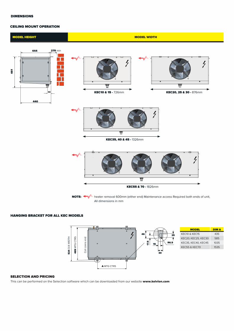
DIMENSIONS
CEILING MOUNT OPERATION
UNITMODEL HEIGHT MODEL WIDTH
444 275 min
46
1
Coi
l con
ns e
nd
48
9 M
TG C
TRS
HANGING BRACKET FOR ALL KEC MODELS
R6.5
25
30
1517.5
46
52
4 O
/A W
IDTH
NOTE: heater removal 600mm (either end) Maintenance access Required both ends of unit, All dimensions in mm
A MTG CTRS
MODEL DIM A
KEC10 & KEC15 435
KEC20, KEC25, KEC30 585
KEC35, KEC40, KEC45 1035
KEC55 & KEC70 1535
SELECTION AND PRICING This can be performed on the Selection software which can be downloaded from our website www.kelvion.com
KEC10 & 15 - 726mm KEC20, 25 & 30 - 876mm
KEC35, 40 & 45 - 1326mm
KEC55 & 70 - 1826mm
50
440

Distributor/Wholesaler
Kelvion UK - Fareham20 Davis Way, Newgate Lane, FarehamHampshire, PO14 1AR, United KingdomTel: +44 (0) 1329 823344www.kelvion.com
Kelvion UK - Birmingham3 Maybrook Road, Birmingham, B76 1AL, United KingdomTel: +44 (0) 121 352 3340 www.kelvion.com
Kelv
ion
UK
© K
CE
Com
mer
cial
air
cool
er J
an 2
018
www.kelvion.com
Recommended