Flowrite™ EA 599 Series
Technical InstructionsDocument No. 155-717
EA-599-18July 7, 2011
SKB/C/D 62UA Series Electronic Valve Actuator 24 Vac Proportional Control Advanced Features
SKB/C
EA
03
79
R1
SKD
Siemens Industry, Inc.
Description The Flowrite EA 599 Series SKB/C/D62UA Electronic Valve Actuator requires a 24 Vac supply and receives a 0 to 10 Vdc or a 4 to 20 mA control signal to proportionally control a valve. This actuator is designed to work with Flowrite VF 599 Series valves and Siemens Industry, Inc. standard valves with a 3/4-inch (20 mm) stroke.
Features • Direct-coupled installation requires no special tools or adjustments
• Visual and electronic stroke indication
• Die-cast aluminum housing
• Manual override
• Spring return to fail-safe position
• Automatic stroke calibration
• Direct or reverse acting
• Adjustable start and span
• Stroke limit control
• Selectable operation direction (direct-acting/reverse acting)
• Choice of linear or equal-percentage flow characteristic
• Maintenance-free
Application These electronic actuators are designed to be used with Flowrite VF 599 Series valves with either 3/4-inch (20 mm) stroke (SKB/D) or a 1-1/2 inch (40 mm) stroke (SKC) in liquid service and steam service applications; or other manufacturer's valves with appropriate Universal Valve Linkage Kit.
Product Numbers Table 1. Product Numbers.
Actuator Stroke
Order Number
SKB62UA
3/4-inch (20 mm)
SKD62UA
1-1/2 inch (40 mm) SKC62UA
Technical Instructions Flowrite EA 599 Series SKB/C/D 62UA Electronic Valve Actuator Advanced Features Document Number 155-717 July 11, 2011
Page 2 Siemens Industry, Inc.
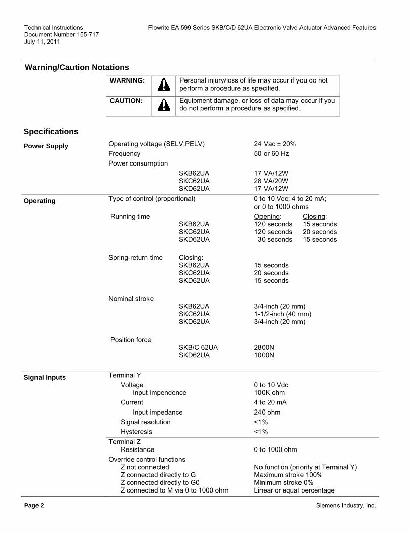
Warning/Caution Notations
Personal injury/loss of life may occur if you do not perform a procedure as specified.
WARNING:
Equipment damage, or loss of data may occur if you do not perform a procedure as specified.
CAUTION:
Specifications Operating voltage (SELV,PELV) 24 Vac ± 20% Power Supply Frequency 50 or 60 Hz Power consumption SKB62UA 17 VA/12W SKC62UA 28 VA/20W SKD62UA 17 VA/12W Type of control (proportional) 0 to 10 Vdc; 4 to 20 mA; or 0 to 1000 ohms
Operating
Running time Opening: Closing: SKB62UA 120 seconds 15 seconds SKC62UA 120 seconds 20 seconds SKD62UA 30 seconds 15 seconds
Spring-return time Closing: SKB62UA 15 seconds SKC62UA 20 seconds SKD62UA 15 seconds
Nominal stroke SKB62UA 3/4-inch (20 mm) SKC62UA 1-1/2-inch (40 mm) SKD62UA 3/4-inch (20 mm)
Position force SKB/C 62UA 2800N SKD62UA 1000N Terminal Y Signal Inputs Voltage 0 to 10 Vdc Input impendence 100K ohm Current 4 to 20 mA Input impedance 240 ohm Signal resolution <1% Hysteresis <1% Terminal Z Resistance 0 to 1000 ohm
Override control functions Z not connected No function (priority at Terminal Y) Z connected directly to G Maximum stroke 100% Z connected directly to G0 Minimum stroke 0% Z connected to M via 0 to 1000 ohm Linear or equal percentage

Flowrite EA 599 Series SKB/C/D 62UA Electronic Valve Actuator Advanced Features Technical Instructions Document Number 155-717 July 11, 2011
Siemens Industry, Inc. Page 3
Signal Inputs, Continued Terminal U Voltage 0 to 9.8 Vdc ± 2% Load impedance >500 ohm Current 4 to 19.6 mA ± 2% Load impedance <500 ohms
Ambient Conditions Media temperature SKD 20°F to 300°F (-7°C to 150°C) SKB/C 20°F to 337°F (-7°C to 170°C) Operation To IEC 721-3-3 Environmental conditions Class 3K5 Temperature SKD 5°F to 122°F (-15°C to 50°C) SKB/C 5°F to 130°F (-15°C to 55°C) Humidity 5% to 95% rh
Transport To IEC 721-2-1 Environmental conditions Class 3K5 Temperature 22°F to 149°F (-5°C to 65°C) Humidity <95% rh
Storage To IEC 721-3-1 Environmental conditions Class 1K3 Temperature SKD 5°F to 122°F (-15°C to 50°C) SKB/C 5°F to 130°F (-15°C to 55°C) Humidity 5% to 95% rh
Agency Certification UL Listed to UL873 C-UL Certified to Canadian standard C22.2 No. 24-93 Meets CE requirements: EMC Directive 89/336/EEC C-tick N474 Protection standard IP54 to EN 60 529 Protection Class III to EN 60 730
Miscellaneous Materials Actuator housing and bracket Die-cast aluminum Housing box and manual adjustor Plastic Conduit opening 1/2-inch NPSM Dimensions See Figures 25 and 26 Weight SKB62UA 18.9 lbs (8,60 kg) SKC62UA 22.5 lbs (10,00 kg) SKD62UA 8.5 lbs (3,85 kg)
Housing NEMA Rating NEMA 1 (Interior only) See Accessories

Technical Instructions Flowrite EA 599 Series SKB/C/D 62UA Electronic Valve Actuator Advanced Features Document Number 155-717 July 11, 2011
Page 4 Siemens Industry, Inc.
Direction of Operation Direct acting / reverse acting 0 to 10 Vdc; 10 to 0 Vdc 4 20 mA; 20 to 4 mA 0 to 1000 ohm/1000 to 0 ohm
Advanced Features
Stroke Limit Control Range of lower limit 0% to 45% adjustable Range of upper limit 100% to 55% adjustable Sequence Control Starting Point of Sequence (Start) 0 to 15V adjustable Operating Range of Sequence (Span) 3 to 15V adjustable Accessories ASC1.6 Auxiliary switch
• Sends a signal to indicate that the valve is in the 0% stroke position.
• The switching point is fixed at the 0% stroke position.
Switching capacity 24 Vac 4A resistive, 2A inductive
Figure 1. Auxiliary Switch.
Lowest recommended current 10 mA
599-00417 Packing heating element for SKD 599-00418 Packing heating element for SKB/C
EA
0393
R1
This heater allows the stem to move freely in valves that control fluids at temperatures below 32°F (0°C). It reduces ice crystal formation on the stem which may damage the packing. Operating Voltage 24 Vac
Figure 2. Packing Heating Element.
Heating Output 20 W
599-10065 The SKB/C actuator is UL listed to meet NEMA Type 3R requirements (a degree of protection against rain, sleet, and damage from external ice formation) when installed with this weather shield and outdoor-rated conduit fittings in the vertical position. See Service Kits for replacement ultraviolet resistant cable ties.
EA
0729
R1
Figure 3. SKB/C Weather Shield.
599-10071 The SKD actuator is UL listed to meet NEMA TYPE 3R requirements (a degree of protection against rain, sleet, and damage from external ice formation) when installed with this weather shield and outdoor-rated conduit fittings in the vertical position. See Service Kits for replacement ultraviolet resistant cable ties.
EA
0853
R1
Figure 4. SKD Weather Shield.

Flowrite EA 599 Series SKB/C/D 62UA Electronic Valve Actuator Advanced Features Technical Instructions Document Number 155-717 July 11, 2011
Siemens Industry, Inc. Page 5
Universal Retrofit Kit Accessories, Continued
VF
03
00
R1
Stem Adapter
Bonnet Adapter
Bonnet AdapterInsert
SetScrew
Opening
Kit contains the parts needed to adapt a valve to the following Siemens 599 Series Flowrite actuators: SKB, SKC, SKD, SQX. Selected valves from the following manufacturers can also be accommodated: Honeywell, Johnson Controls, and Siebe. See your local Siemens representative for details.
Figure 5. Valve Retrofit Kit.
Circuit board replacement 4 668 5751 8 Service Kits Manual override kit 4268 5510 8 Plastic wiring compartment cover 4 104 5582 8 Stem retainer kit Contains one stem nut (Figure 7, Item 6) and one stem retainer clip. 2-1/2 and 3-inch valves 599-10048 4, 5, and 6-inch valves 599-10049 Retainer clamp kit 599-10200 Ultraviolet (UV) resistant cable ties (pkg. of 8) 538-994
WARNING: This product contains a spring under high compression. Do not attempt to disassemble the actuator.
1. Manual Adjuster Valve Details 2. Pressure Cylinder 3. Piston 4. Reservoir 5. Pressure Chamber 6. Pump 7. Return Spring 8. Bypass Valve 9. Coupling 10. Valve Stem 11. Inner Valve 12. Position Indicator (0 to 1)
Figure 6. SKB/C Valve Parts.

Technical Instructions Flowrite EA 599 Series SKB/C/D 62UA Electronic Valve Actuator Advanced Features Document Number 155-717 July 11, 2011
Page 6 Siemens Industry, Inc.
Valve Details, Continued ����
EA
0389
R1
���1. Pressure cylinder
2. Piston 3. Oscillating pump
���4. Return spring 5. Bypass valve 6. Valve stem retainer 7. Manual override knob 8. Position indicator
Figure 7. SKD Valve Parts.
Standard Operation
Figure 8. SKB/C Valve Stem Travel Indication.
EA
0439
R1
1
0
ST
RO
KE
4 20 mA
0 10 Vdc
0
1
0
1
0
1
0
1
EA
0387
R1
3/4 in.(20mm)
Direct Acting
Figure 9. SKD Valve Stem Travel Indication.
The actuator accepts a 0 to 10 Vdc or a 4 to 20 mA control signal. The actuator mounted on a valve produces a stroke proportional to the input signal. When power is turned off or in the event of a power failure, the actuator spring returns the valve to its normal position.

Flowrite EA 599 Series SKB/C/D 62UA Electronic Valve Actuator Advanced Features Technical Instructions Document Number 155-717 July 11, 2011
Siemens Industry, Inc. Page 7
Mounting and Installation
The vertical position is the recommended position for mounting and the only position for NEMA Type 3R rating with the Weather Shield. Acceptable mounting positions are shown in Figure 10.
EA
0133
R2
Not allowed with theWeather Shield
Not allowed inany circumstance
Figure 10. Acceptable Mounting Positions.
Allow four inches (100 mm) around the sides and back of the actuator and eight inches (200 mm) above and to the front of the actuator.
See dimensions in Figure 23 and Figure 24.
Detailed installation instructions for field mounting are shipped with the actuator.
CAUTION:
When removing the knockout do not damage the circuit board. Use the top knockout position, if possible.
Check the wiring for proper connections. Start-up NOTE: The valve body assembly determines the complete assembly action.
Spring Return Function
All SKB/C/D62UA actuators are factory-fitted with a spring-return function. If the control signal or power supply fails, the actuator will return to the 0% stroke position (stem fully retracted).
Start-up, Continued
The override control input (Z) has three modes of operation:
�
U
Z
G
G0
Y
M
100 %
YHmin
StrokeHmax
U
Z
G
G0
Y
M
R
100 %
R [�]0 %
Stroke
50 900
Z-Contact not WiredValve Stroke Follows Control Signal Y
Z-Contact Connected to M Via Resistor RLinear or Equal-Percentage CharacteristicStarting Position at 50 / End Position at 900Y-Input has No Effect
U
Z
G
G0
Y
M
100 %
Y
StrokeVmax
0 %U
Z
G
G0
Y
M
100 %
Y
StrokeVmax
0 %
Z-Contact Connected Directly to GY-Input has No Effect
Z-Contact Connected Directly to G0Y-Input has No Effect
No Function
Actuator Fully Extended
Override with 0 ... 1000
Actuator Fully Retracted
EA
1064
R1
Override Control
NOTE: The Z-modes have a "direct acting" factory setting.

Technical Instructions Flowrite EA 599 Series SKB/C/D 62UA Electronic Valve Actuator Advanced Features Document Number 155-717 July 11, 2011
Page 8 Siemens Industry, Inc.
Stroke Calibration To determine the stroke positions 0% and 100% in the valve, calibration is required when the
valve/actuator are commissioned for the first time. The actuator must be mechanically connected to a valve and must have a supply voltage of 24 Vac. The calibration procedure can be repeated as often as necessary
CAUTION:
Before starting calibration, be sure that the manual adjuster is set to Automatic for the actual values to register.
There is a slot on the printed circuit boards for the actuators. To initiate the calibration procedure, the contacts inside this slot must be short-circuited (possibly with a screwdriver). See
EA
1065
R1Figure 11.
Figure 11. Automatic calibration proceeds as follows (see Figure 12):
• Actuator runs to the 0% stroke position (1), the green LED flashes.
• Actuator then runs to the 100% stroke position (2), the green LED flashes. 0 %
12
3y100 %
Stroke
EA10
66R
1• Measured values are stored in the EPROM.
• The actuator now moves to the position defined by control signal Y or Z (3), and the green LED now glows steady (normal operation). Figure 12.
Automatic Calibration. • Throughout this procedure, output U is inactive, meaning
the values only represent actual positions when the green LED stops flashing and remains on continuously.
Table 2. LED Status.
LED Display Function Action ON Normal Operation Automatic operation
Green Stroke calibration In Progress
Wait for calibration to be completed (LED stops flashing) Flashing
Faulty stroke calibration - Check mounting - Restart stroke calibration (by short-circuiting calibration slot)
ON Internal Error - Replace electronics
Flashing Valve plug jammed Check the valve Red
- Check mains • No power supply OFF - Replace electronics • Faulty electronics

Flowrite EA 599 Series SKB/C/D 62UA Electronic Valve Actuator Advanced Features Technical Instructions Document Number 155-717 July 11, 2011
Siemens Industry, Inc. Page 9
Start-up, Continued
Advanced Features
Calib. Status
EA
1077
R1
LED StatusIndication
Stroke Calibration
Rotary SwitchesLO and UP
ConnectionTerminals
G0AC 24V
50/60Hz 0 ... 10V4 ... 20mA
GG0
Chm
G Y M U Z
OKGreen
Status
Calib.
Red
Calib.
ErrorValveJam
1 2 3 4
Figure 13. DIP Switches.
1 2 3 4
DIP Switches (From Left to Right)
Select Direction of Operation
Sequence Control or
Stroke Limit Control
Selection of Control Signal
Selection of Flow
Characteristic ON Reverse-acting Sequence control 4 to 20 mA Modified* OFF
(Factory Settings) Direct-acting Stroke limit control 0 to 10 Vdc Default
*Changing the default setting will modify an equal percentage valve to a linear flow characteristic. When set to default, the flow characteristic is determined by the valve body.

Technical Instructions Flowrite EA 599 Series SKB/C/D 62UA Electronic Valve Actuator Advanced Features Document Number 155-717 July 11, 2011
Page 10 Siemens Industry, Inc.
• With normally-closed valves, "direct-acting" means that with a 0 Vdc signal input, the
valve is closed. Start-Up, continued • With Normally-open valves, "direct-acting" means that with a 0 Vdc signal input, the valve
is open. Selecting the Direction of Operation
0 %
Y
100 %(10V)
(10V)100 %
Y
0%
100 %
Y
Stroke
0 %
EA10
70R
1Reverse-ActingDire
ct
Direct-Acting Reverse-Acting
Input: 0 to 10 Vdc Input 10 to 0 Vdc 0 Vdc 10 Vdc 4 to 20 mA 20 to 4 mA 4 mA 20 mA 0 to 1000 ohm 1000 to 0 ohm 0 ohm 1000 ohm
Figure 14. Direction of Operation.
Sequence Control or Stroke Limit Control
Check the wiring for proper connections.
NOTE: The valve body assembly determines the complete assembly action.
Table 3. Table 4.
Setting the Stroke Limit Control Setting the Sequence Control
The rotary switches LO and UP can be used to apply an upper and lower limit to the stroke in increments of 3% up to a maximum of 45%.
The rotary switches LO and UP can be used to determine the starting point (Start) or the operating range of a sequence (Span).
100 %
y
UP
LO
0 to 45%
100 to 55%
EA10
71R
1
UP
LO
3 to 15V
0 to 15V
100 %
yEA10
72R
1
Starting Point for
Sequence Control
Operating Range of Sequence
Control
Position of LO
Lower Stroke Limit
Position of UP
Upper Stroke Limit
Position of LO
Position of UP
0 0% 0 100% 0 0V 0 10V 1 3% 1 97% 1 1V 1 10V* 2 6% 2 94% 2 2V 2 10V* 3 9% 3 91% 3 3V 3 3V* 4 12% 4 88% 4 4V 4 4V 5 15% 5 85% 5 5V 5 5V 6 18% 6 82% 6 6V 6 6V 7 21% 7 79% 7 7V 7 7V 8 24% 8 76% 8 8V 8 8V 9 27% 9 73% 9 9V 9 9V A 30% A 70% A 10V A 10V B 33% B 67% B 11V B 11V C 36% C 64% C 12V C 12V D 39% D 61% D 13V D 13V E 42% E 58% E 14V E 14V F 45% F 55% F 15V F 15V *The smallest adjustment is 3 Vdc; Control with 0 to
3 Vdc is possible only via Y.

Flowrite EA 599 Series SKB/C/D 62UA Electronic Valve Actuator Advanced Features Technical Instructions Document Number 155-717 July 11, 2011
Siemens Industry, Inc. Page 11
Start-up, continued When actuator pressure cylinder: Moves outward (0 to 1): Valve opens.
Normally Closed Valve Moves inward (1 to 0): Valve closes.
Normally Open Valve When actuator pressure cylinder: Moves outward (0 to 1): Valve closes. Moves inward (1 to 0): Valve opens.
Three Way Valve When actuator pressure cylinder: Moves outward (0 to 1): Valve opens between port NC and C. Moves inward (1 to 0): Valve opens between ports NO and C.
The measuring voltage at terminal U provides valve stem position feedback to an indicating instrument or building automation system.
Manual operation 180° 1
EA
0161
R1 1 0
1
0
EA
0386
R1 MAN
MANUAL AUTO
INDICATOR
01
1 x 360°= 2mm
EA
0162
R1
Figure 16. SKD Manual Operation.
Turn the manual setting knob clockwise for manual operation. As you begin to turn, a red indicator becomes visible. Each complete revolution (360°) is equal to 3/32-inch (2.5 mm) stroke.
Figure 15. SKB/C Manual Operation.
NOTE: If a signal is sent to the actuator while it is in manual operation, the actuator will move, but the control will not be accurate. The valve cannot be commanded to its 0% position while in manual operation.

Technical Instructions Flowrite EA 599 Series SKB/C/D 62UA Electronic Valve Actuator Advanced Features Document Number 155-717 July 11, 2011
Page 12 Siemens Industry, Inc.
Start-up, Continued When returning to automatic control, you must turn the crank arm of the manual setting knob counterclockwise until the red numbers disappear. It is essential that the window is clear and the crank arm is snapped into position. See Automatic Operation Figure 17.
SKB/C
01
11 x 360°= 2mm
EA
0160
R1
EA
0163
R1
2
Figure 17. SKB/C Automatic Operation.
SKD For automatic operation, the manual override knob must be in the fully closed position. Turn the manual override knob counterclockwise until the red indicator disappears.
01
01
01
01
EA10
73R
1
Figure 18.
Fully Retracted Coupling Fully Extended Coupling ► Stroke = 0% ► Stroke = 100%
CAUTION: The manual adjuster must be rotated counterclockwise to the end stop until the red indicator marked MAN is no longer visible.
Flowrite EA 599 Series SKB/C/D 62UA Electronic Valve Actuator Advanced Features Technical Instructions Document Number 155-717 July 11, 2011
Siemens Industry, Inc. Page 13
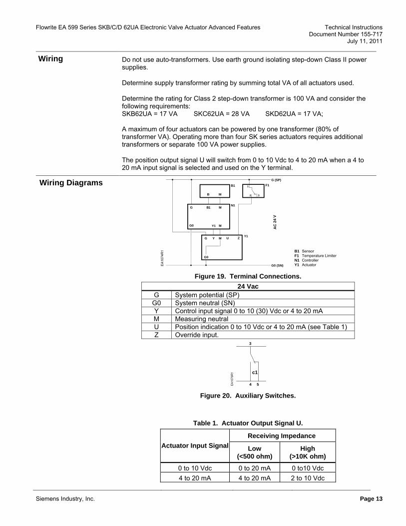
Wiring Do not use auto-transformers. Use earth ground isolating step-down Class II power supplies.
Determine supply transformer rating by summing total VA of all actuators used.
Determine the rating for Class 2 step-down transformer is 100 VA and consider the following requirements: SKB62UA = 17 VA SKC62UA = 28 VA SKD62UA = 17 VA; A maximum of four actuators can be powered by one transformer (80% of transformer VA). Operating more than four SK series actuators requires additional transformers or separate 100 VA power supplies.
The position output signal U will switch from 0 to 10 Vdc to 4 to 20 mA when a 4 to 20 mA input signal is selected and used on the Y terminal.
Wiring Diagrams
G B1 M
G0 Y1
G M Z
G0
Y U
B M
G (SP)F1
Y1
N1
B1
G0 (SN)
32
1
M
SensorTemperature LimiterControllerActuator
B1F1N1Y1
AC
24
V
EA10
74R
1
Figure 19. Terminal Connections.
24 Vac G System potential (SP)
G0 System neutral (SN) Y Control input signal 0 to 10 (30) Vdc or 4 to 20 mA M Measuring neutral U Position indication 0 to 10 Vdc or 4 to 20 mA (see Table 1) Z Override input.
c1
3
4 5EA
1076
R1
Figure 20. Auxiliary Switches.
Table 1. Actuator Output Signal U.
Receiving Impedance Actuator Input Signal Low
(<500 ohm) High
(>10K ohm)
0 to 10 Vdc 0 to 20 mA 0 to10 Vdc 4 to 20 mA 4 to 20 mA 2 to 10 Vdc

Technical Instructions Flowrite EA 599 Series SKB/C/D 62UA Electronic Valve Actuator Advanced Features Document Number 155-717 July 11, 2011
Wiring Diagrams, Continued
EA
0185
R1
3
4
C1
5 EA
0184
R1
G (SP)
24V~ 20W
1
2GO (SN)
Figure 22. Packing Heating Element
599-00418.
Figure 21. Auxiliary Switch
ASC1.6.
Dimensions
9"(228)
2-3/16"(55)
5"(127)
16-1/2"(420)
3-15/16"(99)
6"(152)
6"(152)
14"(335)
EA
0800
R1
Figure 23. Dimensions of 599-10065 SKB\C Weather Shield in Inches (Millimeters).
Page 14 Siemens Industry, Inc.

Flowrite EA 599 Series SKB/C/D 62UA Electronic Valve Actuator Advanced Features Technical Instructions Document Number 155-717 July 11, 2011
Dimensions, Continued
8-13/16(224)
11-1/4(285)
2-9/16(65)
1-15/16(49)
4-1/2(114)
3/4(19)
4-13/16(122)
4-13/16(122)
9-3/8(232)
12-7/8(327)
5(126)E
A08
54R
1
Figure 24. Dimensions of 599-10071 SKD Weather Shield in Inches (Millimeters).
Figure 25. SKB/C Weather Shield, 599-10071 in Inches (Millimeters).
Siemens Industry, Inc. Page 15

Technical Instructions Flowrite EA 599 Series SKB/C/D 62UA Electronic Valve Actuator Advanced Features Document Number 155-717 July 11, 2011
Information in this publication is based on current specifications. The company reserves the right to make changes in specifications and models as design improvements are introduced. Flowrite is a registered trademark of Siemens Industry, Inc. Other product or company names mentioned herein may be the trademarks of their respective owners. © 2011 Siemens Industry, Inc.
Siemens Industry, Inc. Building Technologies Division 1000 Deerfield Parkway Buffalo Grove, IL 60089 USA + 1 847-215-1000
Your feedback is important to us. If you have comments about this document, please send them to
Dimensions, Continued
2-1/2(64)
2-5/8(66)
Ø2-9/16(65)
Ø1-3/4(44)
4-1/8(105)
Ø5(127)
5-5/8(143)
KNOCKOUTFOR STANDARD
1/2" CONDUITCONNECTOR
4-7/8(123)
11-13/16(300)
4-3/4(120)
0
1
0
1
1 0
EA
0385
R1
Figure 26. Dimensions of SKD Actuator in Inches (Millimeters).
Document No. 155-717 Printed in the USA
Page 16
Recommended