*Corresponding author, e-mail: [email protected]
GU J Sci, Part A, 5(3): 101-111 (2018)
Gazi University
Journal of Science PART A: ENGINEERING AND INNOVATION
http://dergipark.gov.tr/gujsa
Carrier-Based PWM Techniques for Multi-Level Inverters: A Comprehensive
Performance Study
Bidyut MAHATO1, Saikat MAJUMDAR
1, Kartick CHANDRA JANA
1
1Department of Electrical Engineering, Indian Institute of Technology (Indian School of Mines), Dhanbad, 826004, India
Article Info
Abstract
This work deals with a carrier based sinusoidal pulse width modulation strategies for three
phase seven level cascaded H-bridge multilevel inverter. Sawtooth and triangular carriers are
presented with the different reference signals i.e. sinusoidal reference, third harmonic injected
sinusoidal reference and trapezoidal reference. Various modulation strategies like phase
disposition pulse width modulation, phase opposition disposition pulse width modulation and
alternate-phase opposition disposition pulse width modulation are implemented for different
reference signals.
The various arrangements of sawtooth and triangular carriers are implemented based on the
three different carrier arrangement techniques such as constant frequency, variable frequency
and carrier overlapping. The comparison table of % total harmonic distortion content has also
been included for different modulation index of each reference signal with various modulation
strategies based on the different arrangements of the carriers. The work has been carried out and
tested in MATLAB/SIMULINK platform and % total harmonic distortion present in phase
voltage and line voltage for three different reference signals has also been studied as well.
Received: 18/06/2018 Accepted: 17/09/2018
Keywords
Carrier-based PWM, Multilevel inverter,
CHB-MLI,
THD
1. INTRODUCTION
To obtain nearly sinusoidal output voltage from the conventional or classical voltage source inverter
(VSI) with variable amplitude and frequency control is one of the major problem [1,2]. The problems like
electromagnetic interferences (EMI), pulsating torques and power loss are some of the common problems
produced in ac motor due to the current harmonics generated by non-sinusoidal output voltage of voltage
source inverter. Thus, the harmonic reduction is a critical issue to be resolved for enhancing the
performance of the VSI. In the year 1975, Baker and Banister introduced multi-level inverter [3]. The
concept of multi-level inverter (MLI) deals with increase in the number of levels thereby increasing the
steps of output voltages. These output voltages forms staircase structure thus reducing the harmonic
distortion [4]. Multilevel inverter are recently popular due to its day-by-day grown up industrial
applications with efficient power generation by use of renewable energy [5,6]. Low size of filter
requirement in multilevel inverter with higher quality output voltages produces a much lesser harmonic
content nearly sinusoidal output [7,8].
Among the three conventional multilevel voltage source inverters such as neutral-point (NPC-MLI) [9],
cascaded H-bridge (CHB-MLI) [10] and flying capacitor (FC-MLI) [11], CHB-MLI started gaining
attention for industrial applications and commercialization [12, 13]. Cascading the required number of
single H-bridge inverter in series produces the multilevel output. CHB-MLI is widespread in the high
power medium-voltage industries due to its modular structure and its continuous un-interrupted working
under faulty module condition [14-17].

102 Bidyut MAHATO, Saikat MAJUMDAR, Kartick CHANDRA JANA/ GU J Sci, Part A, 5(3):101-111(2018)
The harmonic content in the output voltage of the MLI are also improved by pulse width modulation
(PWM) techniques such as sinusoidal pulse width modulation (SPWM), selective harmonic elimination
(SHE), space vector pulse width modulation [18-21]. Carrier based SPWM control techniques have been
widely used due to its easier implementation.
This paper contains comprehensive analysis of harmonic content in the output voltage of three phase
seven level inverter. Three different reference signals i.e. sinusoidal reference, third harmonic injected
sinusoidal reference and trapezoidal reference are employed to study the variations of total harmonic
distortion (THD) content in the output voltage for different arrangements of carrier signals i.e. Phase
Disposition PWM (PD PWM), Phase Opposition Disposition PWM (POD PWM), Alternate Phase
Opposition Disposition PWM (APOD PWM). Nevertheless, these carrier signals are further arranged in
the three more different patterns i.e. Constant Frequency (CF), Variable Frequency (VF) and Carrier
Overlapping (CO) and the THD content for phase voltage as well as line voltage are studied.
2. H-BRIDGE MULTI-LEVEL INVERTER
In the area of multilevel inverter, THD reduction has been a point of concern. Fig. 1 shows the circuit
configuration of three phase seven level cascaded H-bridge inverters. Each H-bridge requires a DC
source. As the H-bridge increases, the output voltage forms more sinusoidal staircase structure. The more
the number of levels, the lesser becomes the THD. Application of multilevel inverters in industries
depends on the economic cost, maintenance and reliability.
''
11S
H-bridge
DCV
DCV
DCV
'
11S
H-bridge
DCV
'
12S
'
13S
'
14S
'
21S
'
22S
'
23S
'
24S
'
31S
'
32S
'
33S
'
34S
DCV
DCV
H-bridge
DCV
DCV
DCV
Phase A Phase B Phase C
n
''
13S
''
12S''
14S'''
12S'''
14S
''
21S
''
22S
''
23S
''
24S
''
31S
''
32S
''
33S
''
34S
'''
21S
'''
22S
'''
23S
'''
24S
'''
31S
'''
32S
'''
33S
'''
34S
'''
11S'''
13S
Figure 1. Circuit diagram of three phase seven level cascaded H-bridge inverter.
Figure 2. Phase voltage of three phase seven level inverter.
-200
0
200
Van
(V
)
-200
0
200
Vbn (
V)
0 0.01 0.02 0.03 0.04 0.05 0.06
-200
0
200
Time (sec)
Vcn
(V
)

Bidyut MAHATO, Saikat MAJUMDAR, Kartick CHANDRA JANA/ GU J Sci, Part A, 5(3):101-111(2018) 103
Phase voltage and line voltage for three phase seven level inverter are shown in Fig. 2. Switching states of
three phase seven level inverter for phase A is described in Table 1. Switching states for phase B and
phase C will be same as shown for phase A. Thus, the control of H-bridge configuration becomes simpler
and easier due to modularity found in each H-bridge.
Table 1. Switching table for Phase A
Voltage
Levels
Switching sequence for Phase A
'11S
'12S
'13S
'14S
'21S
'22S
'23S
'24S
'31S
'32S
'33S
'34S
+3V 1 1 0 0 1 1 0 0 1 1 0 0
+2V 1 1 0 0 1 1 0 0 1 0 1 0
+V 1 1 0 0 1 0 1 0 1 0 1 0
0 1 0 1 0 1 0 1 0 1 0 1 0
-V 0 0 1 1 1 0 1 0 1 0 1 0
-2V 0 0 1 1 0 0 1 1 1 0 1 0
-3V 0 0 1 1 0 0 1 1 0 0 1 1
+3Vdc is generated across phase A when switches '11S & '
12S are ON for first H-bridge, switches
'21S & '
22S are ON for second H-bridge and switches '31S & '
32S are ON for third H-bridge.
+2Vdc is generated across phase A when switch '11S & '
12S are ON for first H-bridge, switch '21S &
'22S are ON for second H-bridge switch '
31S & '33S are ON for third H-bridge.
+Vdc is generated across phase A when switch '11S & '
12S are ON for first H-bridge, switch '21S &
'23S are ON for second H-bridge, switch '
31S & '33S are ON for third H-bridge.
0Vdc is generated across phase A when switch '11S & '
13S are ON for first H-bridge, switch '21S &
'23S are ON for second H-bridge, switch '
31S & '33S are ON for third H-bridge.
-Vdc is generated across phase A when switch '13S & '
14S are ON for first H-bridge, switch '21S &
'23S are ON for second H-bridge, switch '
31S & '33S are ON for third H-bridge.
-2Vdc is generated across phase A when switch '13S & '
14S are ON for first H-bridge, switch '23S &
'24S are ON for second H-bridge, switch '
31S & '33S are ON for third H-bridge.
-3Vdc is generated across phase A when switch '13S & '
14S are ON for first H-bridge, switch '23S &
'24S are ON for second H-bridge, switch '
33S & '34S are ON for third H-bridge.
3. MULTI-CARRIER PWM TECHNIQUE
Carrier based PWM techniques are well established control techniques for multilevel inverters. Recently,
various advancements have been done in the area of control techniques so as to obtain the output voltage
with lesser THD content. Sinusoidal pulse width modulation (SPWM) among the other PWM techniques
is much more popular due to its simpler implementation. Triangular carrier and sawtooth carriers with
different PWM schemes i.e. signals i.e. Phase Disposition PWM (PD PWM), Phase Opposition
Disposition PWM (POD PWM), Alternate Phase Opposition Disposition PWM (APOD PWM) are used
for different arrangement techniques of the carriers [22-26].
3.1. Constant Frequency Based PWM Techniques for Triangular and Sawtooth Carriers
Constant frequency refers that all carriers having the same frequency for a given period of time. Constant
frequency arrangement of carriers for PD PWM, POD PWM, APOD PWM with triangular carriers are

104 Bidyut MAHATO, Saikat MAJUMDAR, Kartick CHANDRA JANA/ GU J Sci, Part A, 5(3):101-111(2018)
shown in Fig. 3(a), Fig. 3(b), Fig. 3(c) respectively whereas constant frequency arrangement of carriers
for PD PWM, POD PWM, APOD PWM with sawtooth carriers are shown in Fig. 3(d), Fig. 3(e), Fig. 3(f)
respectively.
C
arr
iers
Reference Signals
3
2
1
0
1
2
3
0.02 0.025 0.03 0.035 0.04Time (sec)
Reference Signals
Carr
iers
0.02 0.025 0.03 0.035 0.04Time (sec)
3
2
1
0
1
2
3
Figure 3(a). CF-PD PWM Figure 3(b). CF-POD PWM
Carr
iers
3
2
1
0
1
2
30.02 0.025 0.035 0.04
Time (sec)0.03
Reference Signals
Carr
iers
3
3
2
1
0
1
2
0.02 0.025 0.03 0.035 0.04Time (sec)
Reference Signals
Figure 3(c). CF-APOD PWM Figure 3(d). CF-PD PWM
Reference Signals
Carr
iers
3
2
0
1
2
1
3
0.02 0.025 0.03 0.035 0.04Time (sec)
Carr
iers
3
2
0
1
2
1
30.02 0.025 0.035 0.04
Time (sec)0.03
Figure 3(e). CF-POD PWM Figure 3(f). CF-APOD PWM
3.2. Variable Frequency Based PWM Techniques for Triangular and Sawtooth Carriers
Variable frequency refers that all carriers having the different frequency for a given period of time.
Variable frequency arrangement of carriers for PD PWM, POD PWM, APOD PWM with triangular
carriers are shown in Fig. 4(a), Fig. 4(b), Fig. 4(c) respectively whereas constant frequency arrangement
of carriers for PD-PWM, POD PWM, APOD PWM with sawtooth carriers are shown in Fig. 4(d), Fig.
4(e), Fig. 4(f) respectively.
0.02 0.025 0.03 0.035 0.04Time (sec)
Carr
iers
3
3
2
1
0
1
2
Reference Signals
Reference Signals
0.02 0.025 0.03 0.035 0.04Time (sec)
Carr
iers
3
3
2
1
0
1
2
Figure 4(a). VF-PD PWM Figure 4(b). VF-POD PWM

Bidyut MAHATO, Saikat MAJUMDAR, Kartick CHANDRA JANA/ GU J Sci, Part A, 5(3):101-111(2018) 105
Reference Signals
Carr
iers
3
3
2
1
0
1
2
0.02 0.025 0.03 0.035 0.04Time (sec)
0.02 0.025 0.03 0.035 0.04
Time (sec)
Carr
iers
3
3
2
1
0
1
2
Reference Signals
Figure 4(c). VF-APOD PWM Figure 4(d). VF-PD PWM
0.02 0.025 0.03 0.035 0.04Time (sec)
Carr
iers
3
3
2
1
0
1
2
Reference Signals
0.02 0.025 0.03 0.035 0.04
Time (sec)
Carr
iers
3
3
2
1
0
1
2
Reference Signals
Figure 4(e). VF-POD PWM Figure 4(f). VF-APOD PWM
3.3. Carrier Overlapping Based PWM Techniques for Triangular and Sawtooth Carriers
Carrier overlapping refers that all carriers having the same frequency for a given period of time but
overlapped between two carriers. Carrier overlapping arrangement of carriers for PD PWM, POD PWM,
APOD PWM with triangular carriers are shown in Fig. 5(a), Fig. 5(b), Fig. 5(c) respectively whereas
carrier overlapping arrangement of carriers for PD PWM, POD PWM, APOD PWM with sawtooth
carriers are shown in Fig. 5(d), Fig. 5(e), Fig. 5(f) respectively.
0.02 0.025 0.03 0.035 0.04Time (sec)
Carr
iers
3
3
2
1
0
1
2
Reference Signals
0.02 0.025 0.03 0.035 0.04Time (sec)
3
3
2
1
0
1
2
Reference Signals
Figure 5(a). CO-PD PWM Figure 5(b). CO-POD PWM
0.02 0.025 0.03 0.035 0.04Time (sec)
Carr
iers
3
3
2
1
0
1
2
Reference Signals
0.02 0.025 0.03 0.035 0.04Time (sec)
Carr
iers
3
3
2
1
0
1
2
Reference Signals
Figure 5(c). CO-APOD PWM Figure 5(d). CO-PD PWM

106 Bidyut MAHATO, Saikat MAJUMDAR, Kartick CHANDRA JANA/ GU J Sci, Part A, 5(3):101-111(2018)
0.02 0.025 0.03 0.035 0.04Time (sec)
Carr
iers
3
3
2
1
0
1
2
Reference Signals
Carr
iers
3
0
1
2
Reference Signals
0.02 0.025 0.03 0.035 0.04Time (sec)
3
2
1
Figure 5(e). CO-POD PWM Figure 5(f). CO-APOD PWM
4. RESULTS and DISCUSSION
Modeling and simulation of the overall topology has been carried out in MATLAB/Simulink environment
at carrier frequency (fc) of 3 kHz. Various charts has been incorporated to compare the THD content for
sinusoidal reference with triangular as well as sawtooth carriers as shown in Fig. 6(a) and Fig. 6(b)
respectively.
Figure 6(a). Sine Reference with triangular carrier.
Figure 6(b). Sine Reference with sawtooth carrier.
Figure 6(c). Trapezoidal Reference with triangular carrier.

Bidyut MAHATO, Saikat MAJUMDAR, Kartick CHANDRA JANA/ GU J Sci, Part A, 5(3):101-111(2018) 107
Figure 6(d). Trapezoidal Reference with sawtooth carrier.
Figure 6(e). Sine Third Harmonic Reference with triangular carrier.
Figure 6(f). Sine Third Harmonic Reference with sawtooth carrier
Figure 6. %THD content at different modulation index (mi=1, 0.95 and 0.9) (X axis : Different PWM
Techniques at different modulation index; Y axis : %THD content).
The chart shows the %THD content at different modulation index as mentioned. From Fig. 6(a), it has
been observed that CO-PD PWM among the carrier overlapping (CO) arrangements of carriers gives
better result, CF-PD PWM among constant frequency (CF) arrangements of carriers gives better result
and VF-PDPWM among variable frequency (VF) arrangements of carriers gives better result whereas it
can be noticed that all the variable frequency (VF) arrangements of carriers provides better result
compared to the other carrier arrangement techniques i.e. CF & CO. From Fig. 6(b), it is clearly
understood that performance of VF-POD still better compared to CO-POD & CF-POD PWM. Variable
frequency (VF) arrangements of carriers i.e. VF-PD PWM & VF-APOD PWM provides better result
compared to the other carrier arrangement techniques i.e. CF & CO. Taking in account the trapezoidal
reference with triangular and sawtooth carriers, it can be concluded from Fig. 6(c) that VF based carrier
arrangements gives much lesser THD compared to the other carrier arrangements i.e. CO & CF at
different modulation index. Among CO, CF & VF arrangements of the carrier, VF-PD, VF-POD, VF-
APOD PWM stands with the best result at any modulation index as shown in Fig. 6(d). Similarly, %THD
content in third harmonic injected sinusoidal references with triangular and sawtooth carriers for different
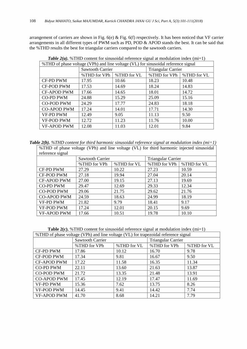
108 Bidyut MAHATO, Saikat MAJUMDAR, Kartick CHANDRA JANA/ GU J Sci, Part A, 5(3):101-111(2018)
arrangement of carriers are shown in Fig. 6(e) & Fig. 6(f) respectively. It has been noticed that VF carrier
arrangements in all different types of PWM such as PD, POD & APOD stands the best. It can be said that
the %THD results the best for triangular carriers compared to the sawtooth carriers.
Table 2(a). %THD content for sinusoidal reference signal at modulation index (mi=1)
%THD of phase voltage (VPh) and line voltage (VL) for sinusoidal reference signal
Sawtooth Carrier Triangular Carrier
%THD for VPh %THD for VL %THD for VPh %THD for VL
CF-PD PWM 17.95 10.66 18.23 10.48
CF-POD PWM 17.53 14.69 18.24 14.83
CF-APOD PWM 17.66 14.65 18.01 14.72
CO-PD PWM 24.88 15.29 25.09 15.16
CO-POD PWM 24.29 17.77 24.83 18.18
CO-APOD PWM 17.24 14.01 17.71 14.30
VF-PD PWM 12.49 9.05 11.13 9.50
VF-POD PWM 12.72 11.23 11.76 10.00
VF-APOD PWM 12.08 11.03 12.01 9.84
Table 2(b). %THD content for third harmonic sinusoidal reference signal at modulation index (mi=1)
%THD of phase voltage (VPh) and line voltage (VL) for third harmonic injected sinusoidal
reference signal
Sawtooth Carrier Triangular Carrier
%THD for VPh %THD for VL %THD for VPh %THD for VL
CF-PD PWM 27.29 10.22 27.23 10.59
CF-POD PWM 27.18 19.94 27.04 20.14
CF-APOD PWM 27.00 19.15 27.13 19.69
CO-PD PWM 29.47 12.69 29.33 12.34
CO-POD PWM 29.06 21.75 29.62 21.76
CO-APOD PWM 24.59 18.63 24.99 18.19
VF-PD PWM 21.82 9.79 18.41 9.17
VF-POD PWM 17.24 12.01 20.15 9.69
VF-APOD PWM 17.66 10.51 19.78 10.10
Table 2(c). %THD content for sinusoidal reference signal at modulation index (mi=1)
%THD of phase voltage (VPh) and line voltage (VL) for trapezoidal reference signal
Sawtooth Carrier Triangular Carrier
%THD for VPh %THD for VL %THD for VPh %THD for VL
CF-PD PWM 17.86 10.12 16.70 9.78
CF-POD PWM 17.34 9.81 16.67 9.50
CF-APOD PWM 17.22 11.58 16.35 11.34
CO-PD PWM 22.11 13.60 21.63 13.87
CO-POD PWM 21.72 13.35 21.48 13.91
CO-APOD PWM 17.45 12.19 17.47 11.69
VF-PD PWM 15.36 7.62 13.75 8.26
VF-POD PWM 14.45 9.41 14.42 7.74
VF-APOD PWM 41.70 8.68 14.21 7.79

Bidyut MAHATO, Saikat MAJUMDAR, Kartick CHANDRA JANA/ GU J Sci, Part A, 5(3):101-111(2018) 109
Table 3(a). %THD content for triangular carrier
%THD for different reference signal for triangular carrier
Sinusoidal
Reference Signal
Trapezoidal
Reference Signal
Third Harmonic Injected
Sinusoidal Reference Signal
CO-PD PWM 15.16 13.87 12.34
CF-PD PWM 10.48 9.78 10.59
VF-PD PWM 9.77 8.26 9.17
CO-POD PWM 18.18 13.91 21.76
CF-POD PWM 14.83 9.50 20.14
VF-POD PWM 10.00 7.74 9.69
CO-APOD PWM 14.30 11.69 18.19
CF-APOD PWM 14.72 11.34 19.69
VF-APOD PWM 9.84 7.79 10.10
Table 3(b). %THD content for sawtooth carrier
%THD for Different Reference Signal for Sawtooth Carrier
Sinusoidal
Reference Signal
Trapezoidal
Reference Signal
Third Harmonic Injected
Sinusoidal Reference Signal
CO-PD PWM 15.29 13.60 12.69
CF-PD PWM 10.66 10.12 10.22
VF-PD PWM 9.05 7.62 9.79
CO-POD PWM 17.77 13.35 21.75
CF-POD PWM 14.69 9.81 19.94
VF-POD PWM 11.23 9.41 12.01
CO-APOD PWM 14.01 12.19 18.63
CF-APOD PWM 14.65 11.58 19.15
VF-APOD PWM 11.03 8.68 10.51
Table. 2(a), Table. 2(b), Table. 2(c) presents %THD content in phase voltage and line voltage for
sinusoidal reference signal, third harmonic injected sinusoidal reference signal and trapezoidal reference
signal respectively at modulation index (mi=1). %THD is measured for CF, CO & VF arrangements of
carriers with PD-PWM, POD-PWM, APOD-PWM. Sinusoidal reference signal based CF-PD PWM, CO-
APOD PWM & VF-PD PWM gives lesser %THD content for both sawtooth and triangular carriers. It
can be said from Table. 2(a) that CO based APOD PWM whereas CF & VF based POD arrangement
generates the lesser %THD content for line voltage while considering sinusoidal as the reference signal.
Third harmonic injected sinusoidal reference signal based CF-PD PWM, CO-PD PWM & VF-PD PWM
gives lesser %THD content for both sawtooth and triangular carriers. It can be concluded from Table.
2(b) that CO based PD PWM whereas CF & VF based PD arrangement generates the lesser %THD
content for line voltage while considering third harmonic injected sinusoidal as the reference signal.
Trapezoidal reference signal based CF-POD PWM, CO-APOD PWM & VF-PD PWM gives lesser
%THD content. CF based POD PWM whereas CO based APOD & VF based PD arrangement generates
the lesser %THD content for line voltage while considering trapezoidal as the reference signal as shown
in Table 2(c). Based on sawtooth and triangular carries, it has been noticed while considering the %THD
content from Table 3(a) & 3(b) that trapezoidal reference signal gives better results than the any other
references. Trapezoidal reference with sawtooth carriers gives better output in respect to THD content
compared to the sawtooth carriers.
5. CONCLUSION
Increasing trends in multilevel inverter for the various industrial applications enhanced the need of
reduction in %THD content so as to restrict the current harmonics being generated by non-sinusoidal
output voltage.

110 Bidyut MAHATO, Saikat MAJUMDAR, Kartick CHANDRA JANA/ GU J Sci, Part A, 5(3):101-111(2018)
This work contains the analysis of %THD for various arrangements of carriers i.e. CO, CF & VF with
various schemes of SPWM control strategies i.e. PD, POD, & APOD for both triangular and sawtooth
carriers at different modulation index. Various aspect of %THD content has been compared and included
as chart as well in tabular form. The result indicates that the VF based techniques gives better THD
compared to any other references either with sawtooth or triangular carrier. Thus, it can be concluded that
the appropriate PWM control strategies to be used depending on performance of the required application.
CONFLICT OF INTEREST
No conflict of interest was declared by the authors.
REFERENCES
[1] Mahato, B., Thakura, P. R., Jana, K. C., “Hardware Design and Implementation of Unity Power
Factor Rectifiers using Microcontrollers,” In 2014 IEEE 6th India International Conference on
Power Electronics (IICPE): 1–5, (2014).
[2] Jha, K. K., Mahato, B., Prakash, P., “Active power factor correction for rectifier using micro-
controller,” In 2016 3rd International Conference on Recent Advances in Information Technology
(RAIT): 331–336, (2016).
[3] Baker, R. H. and Bannister, L. H., Electric Power Converter, U.S. Patent, 3 867 643, (1975).
[4] Rodriguez, J., Lai, J. S., Peng, F. Z., “Multilevel inverters: A survey of topologies, controls, and
applications,” IEEE Trans. Ind. Electron., 49(4): 724–738, (2002).
[5] M. Liserre, T. Sauter, J. Y. Hung, “Future energy systems: Inegrating renewable energy into the smart
power grid through industrial electronics,” IEEE Ind Electron Mag. 4(1): 18–37, (2010).
[6] Abu-Rub, H., Malinowski, M., Al-Haddad, K., “Power electronics for renewable energy systems,
transportation and industrial applications,” John Wiley & Sons, (2014).
[7] Rodríguez, J., Lai, J. S., Peng, F. Z., “Multilevel inverters: A survey of topologies, controls, and
applications,” IEEE Trans Ind. Electron., 49(4): 724–38, (2002).
[8] Rodriguez, J. L., Franquelo, G., Kouro, S., Leon, J. I., Portillo, R. C., Prats, M. A. M. and M. A.
Perez, “Multilevel converters: An enabling technology for high-power applications,” Proceedings of
the IEEE, 97(11): 1786-1817, (2009).
[9] Rodriguez, J., Bernet, S., Steimer, P. K., I. E. Lizama, “A survey on neutral-point-clamped inverters,”
IEEE Trans. Ind. Electron., 57(7): 2219–30, (2010).
[10] Malinowski, M., Gopakumar, K., Rodriguez, J., Perez, M. A., “A survey on Cascaded Multilevel
Inverters, IEEE Trans. Ind. Electron., 57(7): 2197–2206, (2010).
[11] Jing, H. and Corzine, K. A., “Extended operation of flying capacitor multilevel inverters,” IEEE
Trans. Power Electron., 21(1): 140–7, (2006).
[12] Lai, J. S. and Peng, F. Z., “Multilevel Converters - A new breed of power converters,” IEEE
Trans. Ind. Applicat., 32(3): 509–517, (1996).
Bidyut MAHATO, Saikat MAJUMDAR, Kartick CHANDRA JANA/ GU J Sci, Part A, 5(3):101-111(2018) 111
[13] Franquelo, L. G., Rodriguez, J., Leon, J. I., Kouro, S., Portillo, R., Prats, M. A. M., “The age of
multilevel converters arrives,” IEEE Ind. Electron. Mag., 2(2): 28–39, (2008).
[14] Lezana, P. and Ortiz, G., “Extended operation of cascaded multi-cell converters under fault
condition”, IEEE Trans. Ind. Electron., 56(7): 2697–2703, (2009).
[15] Khoucha, F., Lagoun, S. M., Marouani, K., Kheloui, A., Benbouzid, M. E. H., “Hybrid Cascaded
H-Bridge Multilevel-Inverter Induction-Motor-Drive Direct Torque Control for Automotive
Applications,” IEEE Trans. Ind. Electron., 57(3): 892–9, (2010).
[16] Babu, NN. V. S., Fernandes, B. G.,“Cascaded two-level inverter-based multilevel STATCOM for
high-power applications”, IEEE Trans. Power Deliv., 29(3): 993–1001, (2014).
[17] Zheng, Z., Wang, K., Xu, L., Li, Y., “A hybrid cascaded multilevel converter for battery energy
management applied in electric vehicles”, IEEE Trans. Power Electron., 29(7): 3537–46, (2014).
[18] Mahato, B., Raushan, R., Jana, K. C., “Comparative Study of Asymmetrical Configuration of
Multilevel Inverter for Different Levels,” In 2016 3rd International Conference on Recent Advances
in Information Technology (RAIT): 300–303, (2016).
[19] McGrath, B. P. and Holmes, D. G., “Multicarrier PWM strategies for multilevel inverters,” IEEE
Trans. Ind. Electron., 49(2): 858–867, (2002).
[20] Naderi, R. and Rahmati, A., “Phase-shifted carrier PWM technique for general cascaded
inverters”, IEEE Trans. Power Electron., 23(3): 1257-1268, (2008).
[21] Jana, K. C., Biswas, S. K., Chowdhury, S. K., “Performance evaluation of a simple and general
space vector pulse-width modulation-based M-level inverter including over-modulation operation,”
IET Power Electron., 6(4): 809–817, (2013).
[22] Carrara, G. S., M. Gardella., Salutari, R., Sciutto, G., “A new multilevel PWM method: A
theoretical analysis”, IEEE Trans. Power Electron., 7(3): 497–505, (1992).
[23] Black, H. S., “Modulation Theory”, New York: Van Nostrand, (1953).
[24] Bowes, S. R., “New sinusoidal pulse-width modulated inverter,” Proc. Inst. Elect. Eng., 122(11):
1279–1285, (1975).
[25] Tolbert, L. M. and Habetler, T. G., “Novel Multilevel Inverter Carrier-Based PWM Method”
IEEE Trans. on Ind. Applicat., 35(5): 1098-1107, (1999).
[26] Kumar, C., Mahato, B., Raushan, R., Jana, K. C., Maity, T., “Comprehensive study of various
configurations of three-phase Multilevel inverter for different levels,” In 2016 3rd International
Conference on Recent Advances in Information Technology (RAIT):310-315, (2016).
Recommended