January 8, 2008
Landsat Data Continuity Mission
HQ Actions/Issues

2
Topics
• Introduction/Overview
• LDCM Draft Level – 1 Requirements changes
• Requirements review process and results
• Potential Directed Instrument Manifests
• Total Solar Irradiance Sensor (TSIS)
• Thermal Infrared Radiometer Sensor (TIRS)
• Conclusion/Actions

3
LDCM schedule is driven by need to minimize data gap with Landsat 7
• NET July 2011 LRD and L-5/7 fuel depletion in 2010 = 6-12 month data gap • Schedule driver has resulted in “aggressive” instrument schedule
• 40 mo vs. 60 mo typical
Aggressive Instrument Schedule driving OLI Development Risk• Ball implementation “out-of-phase” with typical development
• Procurements of major components in-place and many deliveries expected before Critical Design complete
Schedule Risk accepted with Contract award• Risk highlighted at Source Selection Decision briefing
• 6-month schedule risk identified
SMD AA requested “requirements analysis” to determine options for potential risk reduction/mitigation• Requested legal compliance correlation to performance and• Areas/ideas to reduce schedule driving performance requirements
Introduction/Overview

4
LDCM Draft Level – 1 Requirements
#
Band
Minimum Lower
Band Edge (nm)
Maximum Upper
Band Edge (nm)
Center
Wavelength
(nm)
Maximum Spatial
Resolution
At Nadir
(m)
1 Coastal /Aerosol
433 453 443 30
2 Blue 450 515 482 30
3 Green 525 600 562 30
4 Red 630 680 655 30
5 NIR 845 885 865 30
6 SWIR 1 1560 1660 1610 30
7 SWIR 2 2100 2300 2200 30
8 Panchromatic 500 680 590 15
9 Cirrus 1360 1390 1375 30
10* Thermal 1 10300 11300 10800 120
11* Thermal 2 11500 12500 12000 120
* Contingent upon funding, and requirement trades between program elements, technical requirements, and mission risk as part of the LDCM procurement.
To Be Removed
5
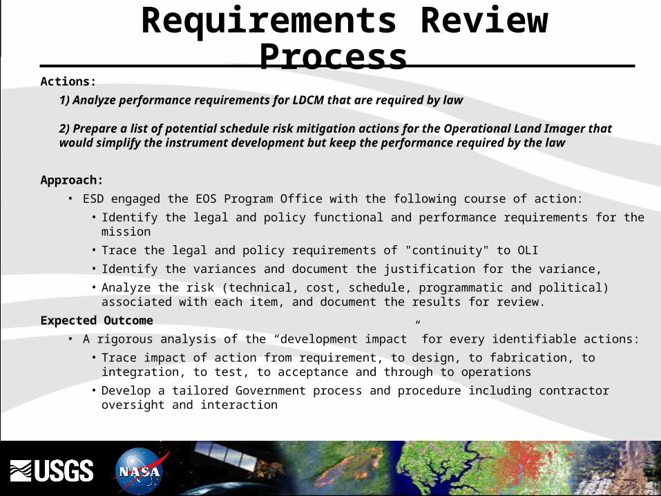
Requirements Review Process Actions:
1) Analyze performance requirements for LDCM that are required by law
2) Prepare a list of potential schedule risk mitigation actions for the Operational Land Imager that would simplify the instrument development but keep the performance required by the law
Approach:
• ESD engaged the EOS Program Office with the following course of action:
• Identify the legal and policy functional and performance requirements for the mission
• Trace the legal and policy requirements of "continuity" to OLI
• Identify the variances and document the justification for the variance,
• Analyze the risk (technical, cost, schedule, programmatic and political) associated with each item, and document the results for review.
Expected Outcome
• A rigorous analysis of the “development impact” for every identifiable actions:
• Trace impact of action from requirement, to design, to fabrication, to integration, to test, to acceptance and through to operations
• Develop a tailored Government process and procedure including contractor oversight and interaction
6
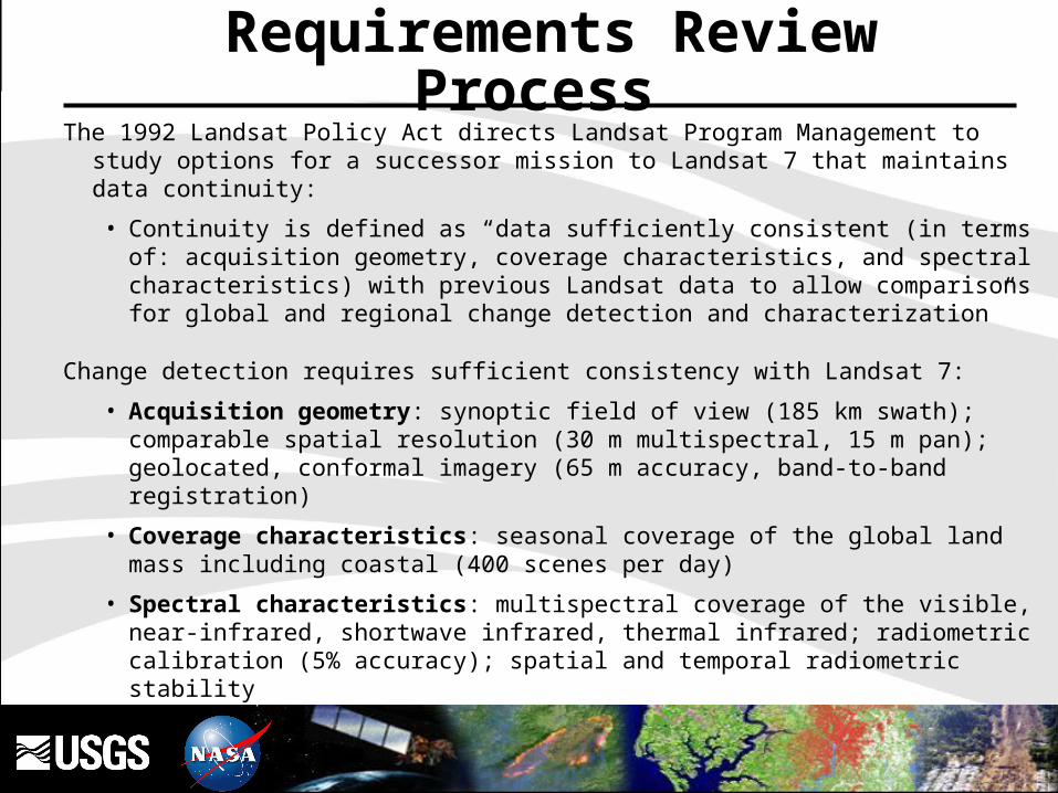
The 1992 Landsat Policy Act directs Landsat Program Management to study options for a successor mission to Landsat 7 that maintains data continuity:
• Continuity is defined as “data sufficiently consistent (in terms of: acquisition geometry, coverage characteristics, and spectral characteristics) with previous Landsat data to allow comparisons for global and regional change detection and characterization”
Change detection requires sufficient consistency with Landsat 7:
• Acquisition geometry: synoptic field of view (185 km swath); comparable spatial resolution (30 m multispectral, 15 m pan); geolocated, conformal imagery (65 m accuracy, band-to-band registration)
• Coverage characteristics: seasonal coverage of the global land mass including coastal (400 scenes per day)
• Spectral characteristics: multispectral coverage of the visible, near-infrared, shortwave infrared, thermal infrared; radiometric calibration (5% accuracy); spatial and temporal radiometric stability
Requirements Review Process
7
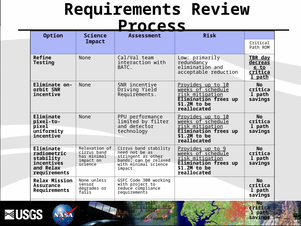
Option Science Impact Assessment RiskCritical Path
ROM
Refine Testing None Cal/Val team interaction with BATC.
Low: primarily redundancy elimination and acceptable reduction
TBR day decrease to critical path
Eliminate on-orbit SNR incentive
None SNR incentive Driving Yield Requirements.
Provides up to 10 weeks of schedule risk mitigationElimination frees up $1.2M to be reallocated
No critical path
savings
Eliminate pixel-to-pixel uniformity incentive
None PPU performance limited by filter and detector technology
Provides up to 10 weeks of schedule risk mitigationElimination frees up $1.2M to be reallocated
No critical path
savings
Eliminate radiometric stability incentivesand Relax requirements
Relaxation of cirrus band has minimal impact on science
Cirrus band stability need not be as stringent as other bands; can be relaxed with minimal science impact.
Provides up to 9 weeks of schedule risk mitigationElimination frees up $1.2M to be reallocated
No critical path
savings
Relax Mission Assurance Requirements
None unless sensor degrades or fails
GSFC Code 300 working with project to reduce compliance requirements
No critical path
savings
Reduce CDRL items None CDRLs were well scrubbed prior to RFP release. A small number of efficiencies found in CDRLs.
No critical path
savings
Relax pixel-to-pixel uniformity requirements
Some relaxation can be tolerated
Relaxation likely reduces requirement below ETM+ performance...
Provides up to 4 weeks of schedule risk mitigation
No critical path
savings
Requirements Review Process

8
Potential Directed Instrument ManifestsTotal Solar Irradiance Sensor (TSIS)
• De-manifest of capability from NPOESS - OSTP chartered continuity study (NOAA led)• Study identified LDCM as potential near-term gap-filler platform• Initiated vendor (LASP) accommodation study to reduce risk• Included in spacecraft accommodation studies • Final spacecraft RFO includes TSIS accommodation through design and as option for
implementation• Manifest remains unauthorized and TBD
Thermal Infrared Radiometer Sensor (TIRS)• Removed from baseline in 2002 - determined to be not commercially viable• NPOESS OLI: Technical (volume and mass) and budget constrained manifest• Currently, budget profile cannot support development• Following 2005 OSTP re-direction, user community lobbying increased and stakeholder
inquiries escalated• Congressional interest manifested in draft NASA 2008 appropriations language
• The term “thermal” missing from final appropriation-now reads: “…data continuity…”• Final spacecraft RFO includes TIR accommodation through design and as option for
implementation: Manifest remains unauthorized and TBD• Potential threat to LRD: 12-months currently, but will increase

9
Conclusion
• Baseline Mission (OLI-only) currently on-track for July 2011 LRD
• Requirements driver reviews conducted to mitigate OLI development risk
• TSIS and TIRS manifest unauthorized
• Initiated risk mitigation
• TIRS Instrument Team Study completed
• Accommodation studies completed
• Inclusion in s/c design and options for implementation
• Potential threat to mission LRD due to TIRS development schedule
10
BACK-UP

11
Implementation Roles and Responsibilities NASALead the mission development
• Mission-level systems engineering
Develop the LDCM Space Segment
• Instrument, Spacecraft and Launch Vehicle procurements
• Satellite integration and launch
Procure the Mission Operations Element for the USGS • Command & Control, Scheduling, Long-Term Trending/Analysis, and Flight
Dynamics capabilities• Support for Observatory I&T/Launch Site • On-Orbit Sustaining Engineering
Lead the pre-launch and orbital verification, calibration, validation and characterization
Manage on-orbit checkout of the LDCM system
Transfer the LDCM instrument and mission operations contract to DOI/USGS following on-orbit check-out and acceptance
After launch and on-orbit acceptance, support DOI/USGS with calibration, validation, and instrument characterization
Provide scientific and technical support for the Landsat Science Team
Support DOI/USGS operations anomaly investigations
12
Provide funding for the LDCM mission operations procurement
Implement a ground data processing capability
Implement a capability to ingest, archive, process, and distribute LDCM data
Following on-orbit check-out and acceptance, assume contract management and funding responsibility for the LDCM instrument and mission operations contracts
Provide long-term archive services
Convene a Landsat Mission Science Team
After on-orbit acceptance
• Lead the calibration, validation, and characterization
• Lead anomaly investigations
Implementation Roles and Responsibilities USGS

13
LANDSAT30+ Years of Continuous Land Observations
14
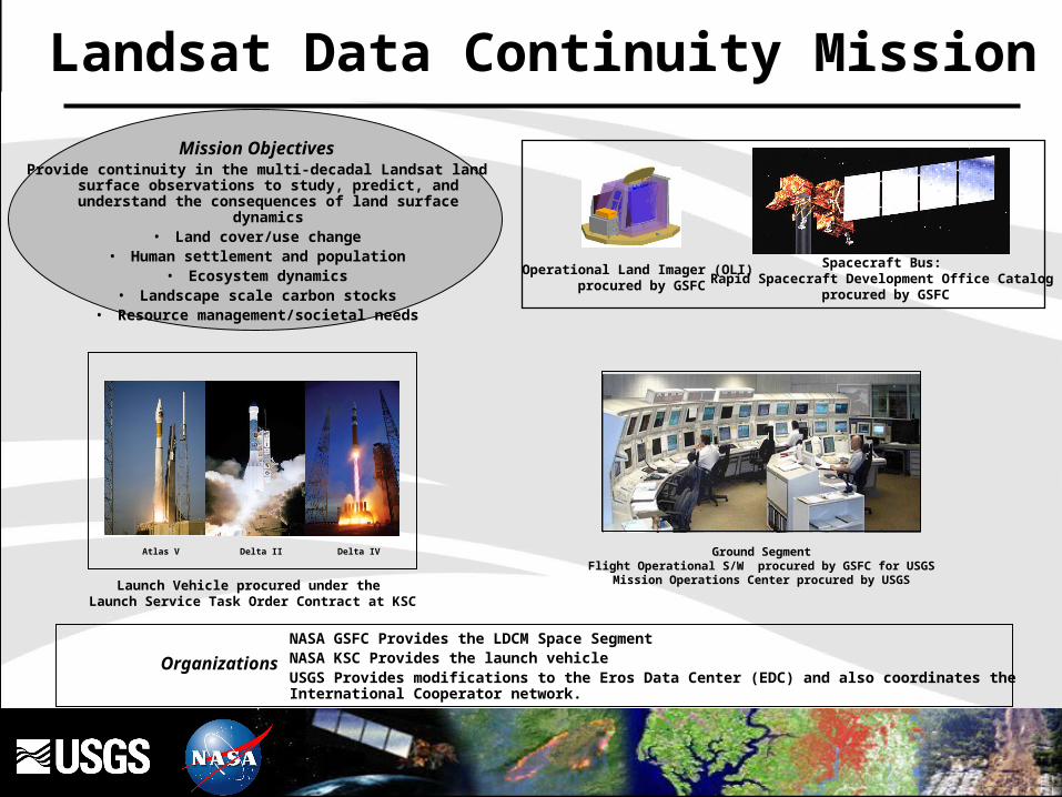
Launch Vehicle procured under the Launch Service Task Order Contract at KSC
Atlas V Delta II Delta IV
Mission ObjectivesProvide continuity in the multi-decadal Landsat land surface
observations to study, predict, and understand the consequences of land surface dynamics
• Land cover/use change• Human settlement and population
• Ecosystem dynamics• Landscape scale carbon stocks
• Resource management/societal needs
Operational Land Imager (OLI) procured by GSFC
Spacecraft Bus:Rapid Spacecraft Development Office Catalog
procured by GSFC
Organizations
NASA GSFC Provides the LDCM Space SegmentNASA KSC Provides the launch vehicleUSGS Provides modifications to the Eros Data Center (EDC) and also coordinates the International Cooperator network.
Ground SegmentFlight Operational S/W procured by GSFC for USGS
Mission Operations Center procured by USGS
Landsat Data Continuity Mission

15
LDCM is one of two measurements required of NASA by Public Law • Public Law 102-555, the Land Remote Sensing Policy Act of 1992 and
Presidential Decision Directive/NSTC-3 • NASA and DOI/USGS established as Landsat Program Management
LDCM schedule is driven by need to minimize data gap with Landsat 7 • NET July 2011 LRD and L-5/7 fuel depletion in 2010 = 6-12 month data gap • Schedule driver has resulted in “Aggressive” instrument schedule
• 40 mo vs. 60 mo typical• USGS spearheading, with NASA co-chairing, the Landsat Data Gap Study
Team investigation of alternatives to at least partially offset the data gap• Technical investigations of data from India’s ResourceSat and
China/Brazil CBERS satellites complete: Targeting Summer 2007 for “Data Gap Implementation” Report
LDCM will not have a thermal infrared capability• Cost estimate for thermal infrared exceeds available budget• If added to the development, an extension of the Data Gap will occur
Introduction/Overview
16
Land Imaging Policy is now under consideration for ratification:
• The Future of Land Imaging Interagency Working Group (FLI IWG) was convened by the National Science and Technology Council (NSTC) to address technical, financial, and managerial stability for operational land imaging (Marburger Dec 2005 memo)
• FLI IWG convened from Feb-Nov 06 and performed systematic analysis of the state of U.S. civil land imaging.
• The IWG has completed a report with recommended U.S. Policy change
• “A PLAN FOR A NATIONAL LAND IMAGING PROGRAM”
– published Aug 2007
Background– continued-

17
Acquisition approach includes separate procurements for:
• instrument
• spacecraft
• launch vehicle and
• mission operations element (MOE)
NASA Goddard Space Flight Center (GSFC) will serve as the mission system integrator
Launch services provided by the NASA Launch Services at Kennedy Space Center (KSC)
Open competition for the instrument
• Contract awarded to Ball Aerospace and Technologies Corp – Jul 2007
Rapid Spacecraft Development Office (RSDO) contract procurement for the spacecraft
• RSDO spacecraft studies awarded Apr 2007 : Ball, Loral, General Dynamics, OSC
NASA in coordination with the USGS will compete the Mission Operations Element (MOE)
• To be released and awarded in early CY 2008.
LDCM will have a 5-year mission life
Following on-orbit verification, ownership will transfer to the USGS
USGS will operate the spacecraft and manage the data
LDCM Development Status
Acquisition Approach
18
Acquisition includes separate procurements for:
Operational Land Imager (OLI) Instrument
• Final RFP released Jan 8, 2007
• Awarded to Ball Aerospace and Technologies Corp in Jul., 2007
• Award protested, GAO denied protest Nov. 9, 2007
• Instrument Systems Requirements Review held Nov. 6-7, 2007
• Successful Integrated Baseline Review held Nov. 13-15, 2007
• Mission Design Review to be held Mar., 2008
Spacecraft Procurement
• RSDO on-ramp opened Oct 25, 2006, closed Dec 15, 2006
• Four contractors (Ball, Loral, GD and OSC) selected for 4-month study phase (accommodation risk reduction) : Apr 30, 2007
• RFO to be released in the early Dec., 2007
LDCM Development Status
19
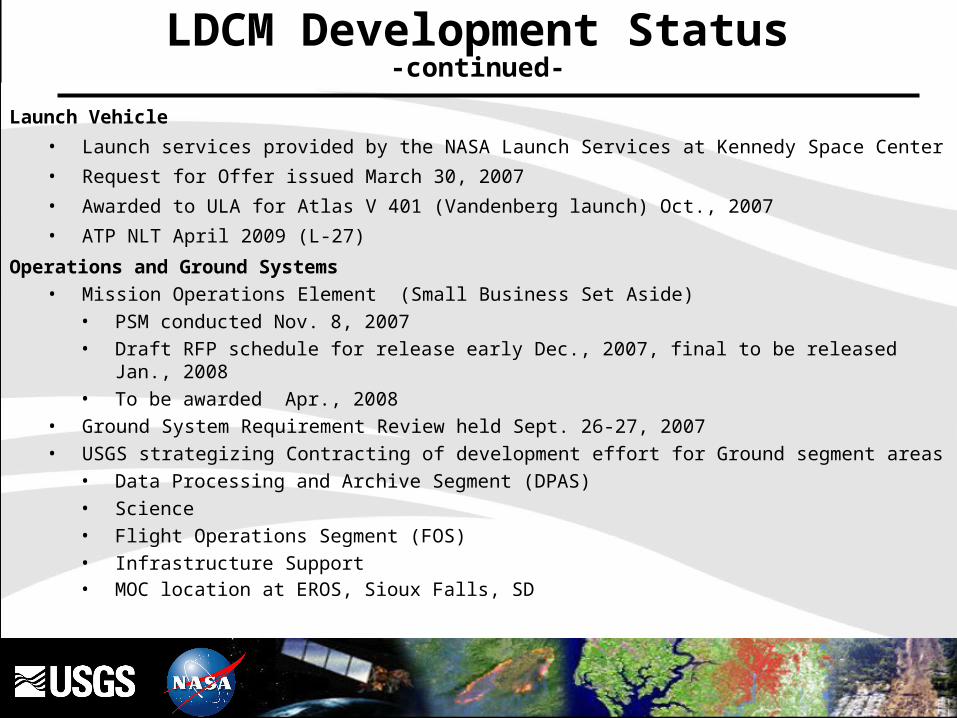
LDCM Development Status-continued-
Launch Vehicle
• Launch services provided by the NASA Launch Services at Kennedy Space Center
• Request for Offer issued March 30, 2007
• Awarded to ULA for Atlas V 401 (Vandenberg launch) Oct., 2007
• ATP NLT April 2009 (L-27)
Operations and Ground Systems• Mission Operations Element (Small Business Set Aside)
• PSM conducted Nov. 8, 2007• Draft RFP schedule for release early Dec., 2007, final to be released Jan., 2008• To be awarded Apr., 2008
• Ground System Requirement Review held Sept. 26-27, 2007• USGS strategizing Contracting of development effort for Ground segment areas
• Data Processing and Archive Segment (DPAS)• Science• Flight Operations Segment (FOS)• Infrastructure Support• MOC location at EROS, Sioux Falls, SD

20
• Mission Lifetime: At least 5 years.• Consumable Resources: At least 10 years of mission operation.• Earth Spatial-Temporal Coverage: At least seasonal coverage of the global
land mass.• Landsat Data Consistency: Consistent with Landsat 7 Enhanced Thematic
Mapper Plus (ETM+) data • in terms of acquisition geometry, calibration, coverage characteristics,
spectral and spatial characteristics, output product quality and data availability
• to allow comparisons for the detection and quantitative characterization of changes on the global land surface.
• Acquisition Geometry• Worldwide Reference System: Worldwide Reference System (WRS-2).• Equatorial Observation Time: 10:00 a.m. + or – 15 minutes.• Coverage Characteristics: At least once every 16 days.• Spectral Characteristics: (SEE TABLE)• Acquisition of thermal data is under investigation
LDCM Draft Level – 1 Requirements
21
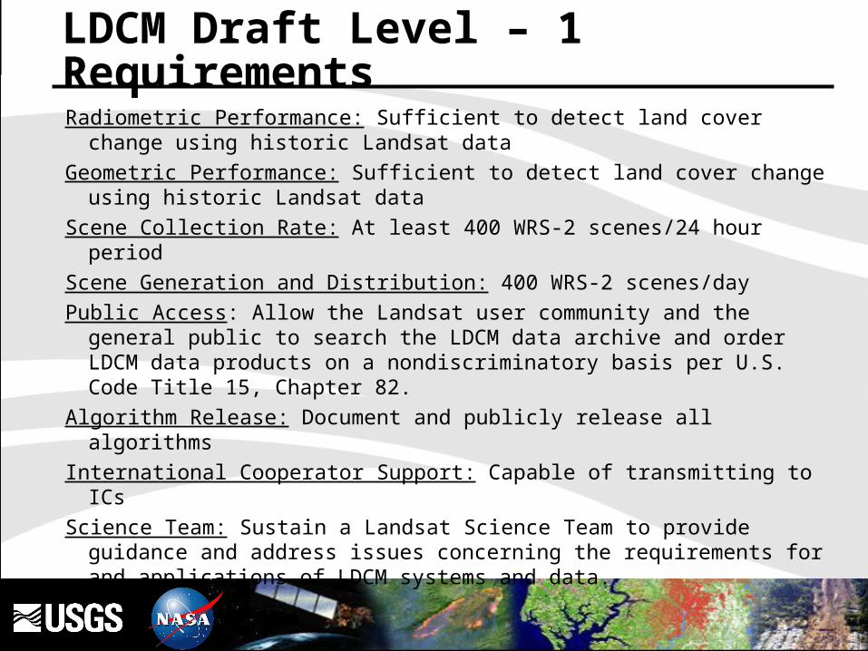
Radiometric Performance: Sufficient to detect land cover change using historic Landsat data
Geometric Performance: Sufficient to detect land cover change using historic Landsat data
Scene Collection Rate: At least 400 WRS-2 scenes/24 hour period
Scene Generation and Distribution: 400 WRS-2 scenes/day
Public Access: Allow the Landsat user community and the general public to search the LDCM data archive and order LDCM data products on a nondiscriminatory basis per U.S. Code Title 15, Chapter 82.
Algorithm Release: Document and publicly release all algorithms
International Cooperator Support: Capable of transmitting to ICs
Science Team: Sustain a Landsat Science Team to provide guidance and address issues concerning the requirements for and applications of LDCM systems and data.
LDCM Draft Level – 1 Requirements

22
LDCM Development StatusCritical Milestones
2007 2008July August September October November December January February March
EndDate
StartDate
TASK
7/18/077/18/07Spacecraft Acceptance Review1
2/26/117/20/07OLI Instrument ATP2
6/20/119/11/07Launch Vehicle Selection Letter3
9/25/079/25/07Ground System SRR4
10/31/0710/31/07S/C Bus Draft RFO Release5
11/6/0711/6/07OLI Instrument SRR6
11/13/0711/13/07OLI Instrument IBR7
11/27/0711/27/07S/C Bus RFO Release8
12/3/0711/19/07MOE Draft RFP Release9
1/16/081/3/08MOE Final RFP Release10
1/11/0812/21/07S/C Bus RFO Response Due11
3/3/083/3/08LDCM Mission MDR/SRR12
3/4/082/21/08Spacecraft Bus Selection13
3/4/082/21/08Spacecraft ATP14
3/4/083/4/08OLI Instrument PDR15
1
1
4
4
4
23
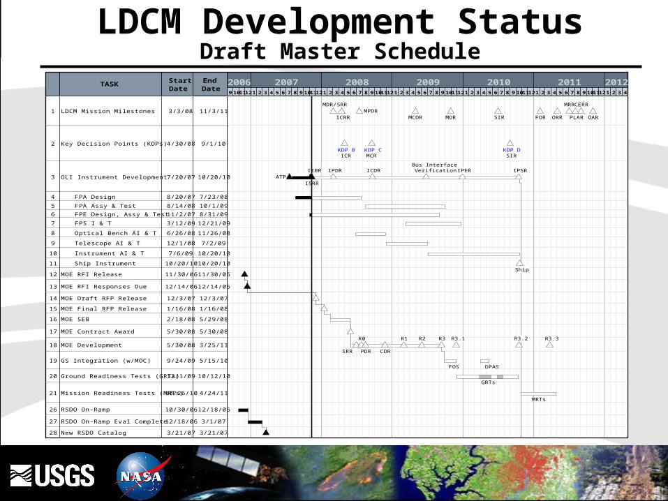
LDCM Development StatusDraft Master Schedule2006 2007 2008 2009 2010 2011 20129 1011 12 1 2 3 4 5 6 7 8 9 1011 12 1 2 3 4 5 6 7 8 9 1011 12 1 2 3 4 5 6 7 8 9 1011 12 1 2 3 4 5 6 7 8 9 1011 12 1 2 3 4 5 6 7 8 9 1011 12 1 2 3 4
EndDate
StartDate
TASK
11/3/113/3/08LDCM Mission Milestones1
9/1/104/30/08Key Decision Points (KDPs)2
10/20/107/20/07OLI Instrument Development3
7/23/088/20/07FPA Design4
10/1/098/14/08FPA Assy & Test5
8/31/0911/2/07FPE Design, Assy & Test6
12/21/093/12/09FPS I & T7
11/26/086/26/08Optical Bench AI & T8
7/2/0912/1/08Telescope AI & T9
10/20/107/6/09Instrument AI & T10
10/20/1010/20/10Ship Instrument11
11/30/0611/30/06MOE RFI Release12
12/14/0612/14/06MOE RFI Responses Due 13
12/3/0712/3/07MOE Draft RFP Release14
1/16/081/16/08MOE Final RFP Release15
5/29/082/18/08MOE SEB16
5/30/085/30/08MOE Contract Award17
3/25/115/30/08MOE Development18
5/15/109/24/09GS Integration (w/MOC)19
10/12/1012/1/09Ground Readiness Tests (GRTs)20
4/24/1110/26/10Mission Readiness Tests (MRTs)21
12/18/0610/30/06RSDO On-Ramp26
3/1/0712/18/06RSDO On-Ramp Eval Complete27
3/21/073/21/07New RSDO Catalog28
MDR/SRR
ICRRMPDR
MCDR MOR SIR FOR ORR
MRR
PLAR
CERR
OAR
KDP BICR
KDP CMCR
KDP DSIR
ATPISRR
IIBR IPDR ICDRBus Interface
Verification IPER IPSR
Ship
SRR
R0
PDR CDR
R1 R2 R3 R3.1 R3.2 R3.3
FOS DPAS
GRTs
MRTs
24
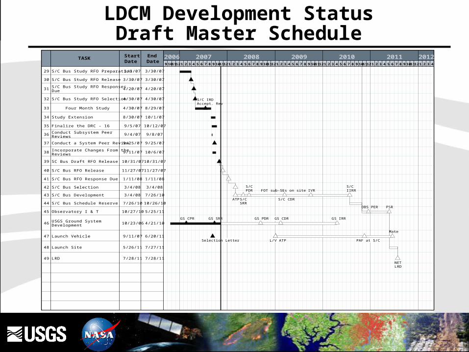
2006 2007 2008 2009 2010 2011 20129 1011 12 1 2 3 4 5 6 7 8 9 1011 12 1 2 3 4 5 6 7 8 9 1011 12 1 2 3 4 5 6 7 8 9 1011 12 1 2 3 4 5 6 7 8 9 1011 12 1 2 3 4 5 6 7 8 9 1011 12 1 2 3 4
EndDate
StartDate
TASK
3/30/071/3/07S/C Bus Study RFO Preparation29
3/30/073/30/07S/C Bus Study RFO Release30
4/20/074/20/07S/C Bus Study RFO Responses Due
31
4/30/074/30/07S/C Bus Study RFO Selection32
8/29/074/30/07 Four Month Study33
10/1/078/30/07Study Extension34
10/12/079/5/07Finalize the DRC - 1635
9/8/079/4/07Conduct Subsystem Peer Reviews
36
9/25/079/25/07Conduct a System Peer Review 37
10/6/079/11/07Incorporate Changes From the Reviews
38
10/31/0710/31/07SC Bus Draft RFO Release39
11/27/0711/27/07S/C Bus RFO Release40
1/11/081/11/08S/C Bus RFO Response Due41
3/4/083/4/08S/C Bus Selection42
7/26/103/4/08S/C Bus Development43
10/26/107/26/10S/C Bus Schedule Reserve44
5/25/1110/27/10Observatory I & T45
4/21/1010/23/06USGS Ground System Development46
6/20/119/11/07Launch Vehicle47
7/27/115/26/11Launch Site48
7/28/117/28/11LRD49
S/C IRDAccept. Rev
ATP S/CSRR
S/CPDR FOT sub-SEs on site
S/C CDR
IVRS/CIIRR
OBS PER PSR
GS CPR GS SRR GS PDR GS CDR GS IRR
Selection Letter L/V ATP PAF at S/C
Mate
NETLRD
LDCM Development StatusDraft Master Schedule

25
Source Selection Information See FAR 3.104 Page 31
Band Elimination Impact to ScienceElimination will impair the mitigation of current limitations to the systematic monitoring of
the global land surface and coastal zones for change detection.
• Cirrus Band Elimination• Precludes ability to detect thin cirrus cloud contamination of other spectral bands
•Increases uncertainty of surface reflectance retrievals
•Increases errors of commission (false positives) in change detection
• Coastal / Aerosol Band Elimination
• Restricts ability to assess coastal zone and inland lake water quality; limits retrieval of chlorophyll, suspended matter, and colored dissolved organic matter concentrations.
• Precludes aerosol retrievals leading to improved atmospheric correction
• Reduction of SNR, quantization, saturation levels• Reduce accuracy of land cover maps, land cover characterization,
and change detection by reducing radiometric sensitivity and dynamic range
• Inability to map bright surfaces: ice, snow, deserts inability to detect glacial flow velocities -
26
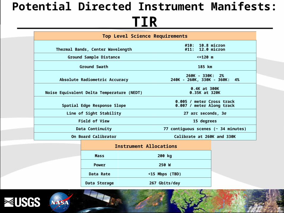
Top Level Science Requirements
Thermal Bands, Center Wavelength#10: 10.8 micron#11: 12.0 micron
Ground Sample Distance <=120 m
Ground Swath 185 km
Absolute Radiometric Accuracy260K - 330K: 2%
240K - 260K, 330K - 360K: 4%
Noise Equivalent Delta Temperature (NEDT)0.4K at 300K
0.35K at 320K
Spatial Edge Response Slope0.005 / meter Cross track0.007 / meter Along track
Line of Sight Stability 27 arc seconds, 3σ
Field of View 15 degrees
Data Continuity 77 contiguous scenes (~ 34 minutes)
On Board Calibrator Calibrate at 260K and 330K
Instrument Allocations
Mass 200 kg
Power 250 W
Data Rate <15 Mbps (TBD)
Data Storage 267 Gbits/day
Potential Directed Instrument Manifests:
TIR

27
LASP involved to provide accommodation studies • Initiated development of mechanical and electrical ICDs, ops con,
disturbance sources, support study, etc.• LASP has provided a no cost modification to the TSIS design
• Allows accommodation by any S/C vendor • Reduced mass by 12kg• Reduces jitter
TSIS added to RSDO Accommodation Study• Jitter, mass, power, T&C• Launch vehicle interface• Orbital debris mitigation• Field-of-view• Operations, calibration
Expanded Jitter Study• Jitter analysis being performed by GSFC, LASP, and S/C Vendors
Manifest remains unauthorized and TBD
Potential Directed Instrument Manifests:
TSIS

28
TSIS ON NPOESS• 162 kg NTE mass estimate• 1.1m x1.1m x1.1m
TSIS ON LDCM• 150 kg NTE mass estimate• 0.9m x1.1m x0.4m
Potential Directed Instrument Manifests:
TSIS
29
Collaboration with International partners explored, but remains unfruitful
HQ chartered TIRS Risk Reduction Activity for summer 2006
Independent studies conducted from 2004 – 2006
• Led to selection of microbolometer as cost effective solution
Risk Reduction Activity completed the following tasks:
• Proof of feasibility of the technical concept with appropriate system technical and performance margins.
• Developed schedule and cost for the TIRS
System Definition Review held September 12, 2007
Risk Reduction effort stopped Sep., 2007
Final spacecraft RFO includes TIRS accommodation through design and as option for implementation
Manifest remains unauthorized and TBD
Potential Directed Instrument Manifests:
TIRS
30
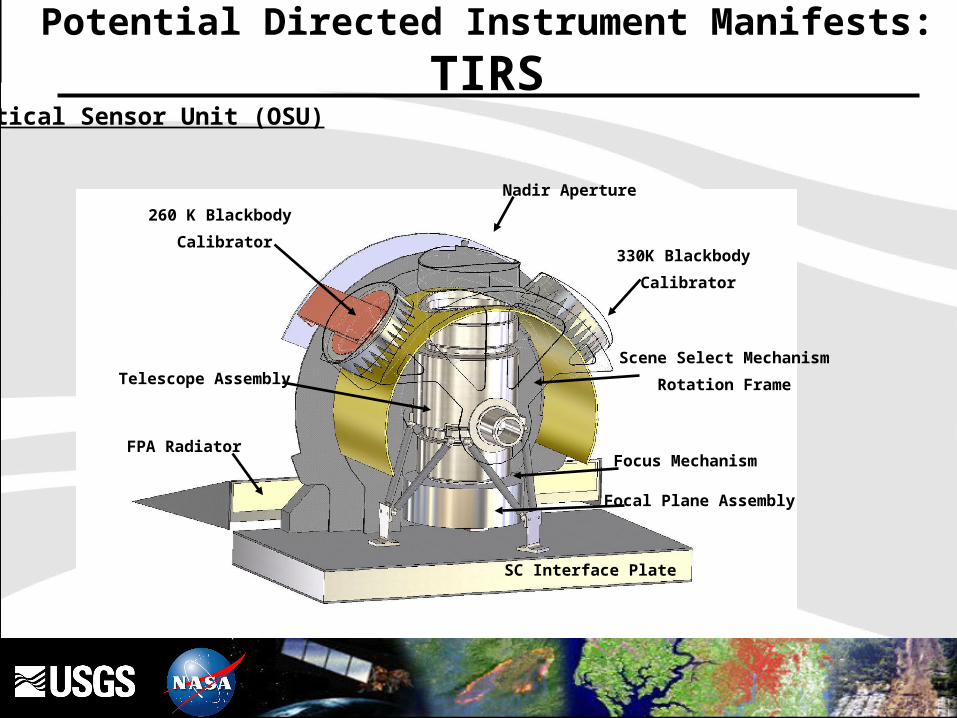
260 K Blackbody
Calibrator330K Blackbody
Calibrator
Scene Select Mechanism
Rotation FrameTelescope Assembly
SC Interface Plate
Focus Mechanism
Focal Plane Assembly
Nadir Aperture
FPA Radiator
Optical Sensor Unit (OSU)
Potential Directed Instrument Manifests:
TIRS
Recommended