Jacking pipesIssue 1
Contents
Jacking pipes 1
The jacking technique (microtunnelling) 1
Benefits of pipe jacking 2
Technical 2
Safety 2
Economic 2
Environmental 2
Steel reinforced concrete pipes (SRCP) 3
Benefits of reinforced concrete jacking pipes 3
Fixed steel collar pipes 4
Loose steel collar pipes 9
Selection of jacking pipes 10
Vitrified clay pipes 13
Features and benefits 13
Product range 15
Connection to standard pipes and
access chambers
18
Precast solutions 20
Contact information 21
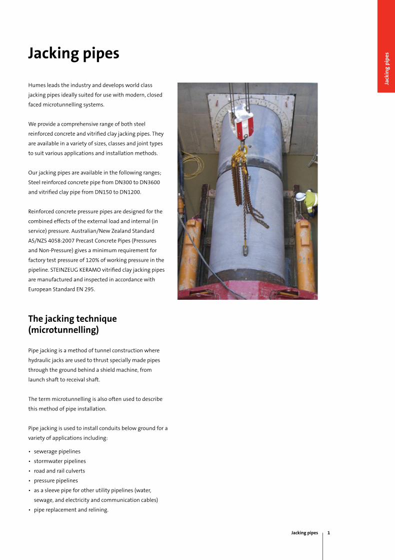
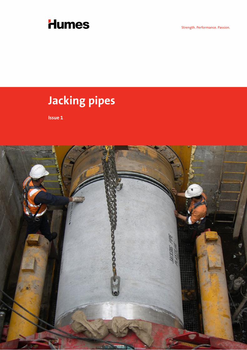
Humes leads the industry and develops world class
jacking pipes ideally suited for use with modern, closed
faced microtunnelling systems.
We provide a comprehensive range of both steel
reinforced concrete and vitrified clay jacking pipes. They
are available in a variety of sizes, classes and joint types
to suit various applications and installation methods.
Our jacking pipes are available in the following ranges;
Steel reinforced concrete pipe from DN300 to DN3600
and vitrified clay pipe from DN150 to DN1200.
Reinforced concrete pressure pipes are designed for the
combined effects of the external load and internal (in
service) pressure. Australian/New Zealand Standard
AS/NZS 4058:2007 Precast Concrete Pipes (Pressures
and Non-Pressure) gives a minimum requirement for
factory test pressure of 120% of working pressure in the
pipeline. STEiNZEug KERAmO vitrified clay jacking pipes
are manufactured and inspected in accordance with
European Standard EN 295.
The jacking technique (microtunnelling)
Pipe jacking is a method of tunnel construction where
hydraulic jacks are used to thrust specially made pipes
through the ground behind a shield machine, from
launch shaft to receival shaft.
The term microtunnelling is also often used to describe
this method of pipe installation.
Pipe jacking is used to install conduits below ground for a
variety of applications including:
• sewerage pipelines
• stormwater pipelines
• road and rail culverts
• pressure pipelines
• as a sleeve pipe for other utility pipelines (water,
sewage, and electricity and communication cables)
• pipe replacement and relining.
Jacking pipes
Jacking pipes 1
Jack
ing
pip
es
Benefits of pipe jacking
Technical
• inherent strength of lining.
• Smooth internal finish giving good flow characteristics.
• No requirement for secondary lining.
• Considerably less joints than a segmental tunnel.
• Prevention of ground water ingress by use of pipes
with sealed flexible joints.
• Provision of invert channels in larger pipes to contain
the dry weather flow of a sewer in a combined system.
Safety
Pipe jacking is an inherently safer method than open
trench construction or when considering the risks
associated with deep, large section, open excavations:
• major reduction in man-hours, opportunities for
accidents to occur are less with pipe jacking.
• in busy urban centres, trenchless operation
will not interfere with pedestrian and motor
traffic movements.
• There is significant reduction in the risk of injury as a
result of utility strikes and interface with the public.
• Less risk of settlement.
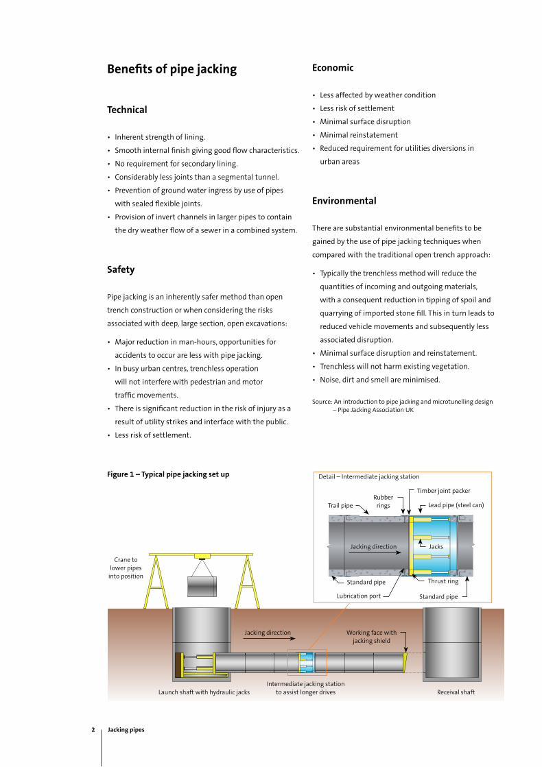
Figure 1 – Typical pipe jacking set up
Economic
• Less affected by weather condition
• Less risk of settlement
• minimal surface disruption
• minimal reinstatement
• Reduced requirement for utilities diversions in
urban areas
Environmental
There are substantial environmental benefits to be
gained by the use of pipe jacking techniques when
compared with the traditional open trench approach:
• Typically the trenchless method will reduce the
quantities of incoming and outgoing materials,
with a consequent reduction in tipping of spoil and
quarrying of imported stone fill. This in turn leads to
reduced vehicle movements and subsequently less
associated disruption.
• minimal surface disruption and reinstatement.
• Trenchless will not harm existing vegetation.
• Noise, dirt and smell are minimised.
Source: An introduction to pipe jacking and microtunelling design – Pipe Jacking Association uK
Crane to lower pipes
into position
Launch shaft with hydraulic jacksintermediate jacking station
to assist longer drives Receival shaft
Working face with jacking shield
Jacking direction
Trail pipe
Jacking direction
Rubber rings
Timber joint packer
Lead pipe (steel can)
Jacks
Lubrication port
Standard pipe
Standard pipe
Thrust ring
Detail – intermediate jacking station
2 Jacking pipes
Steel reinforced concrete pipes (SRCP)
Humes is Australia’s leading manufacturer of SRCP.
We have a wide range of diameters, lengths and
strengths available. Our SRCP has a proven track record
and can be custom designed for applications such as
drainage, sewage, water supply and irrigation.
A milestone was achieved when Humes' DN2100,
fixed steel collar pipes were jacked 1,030 m without
any intermediate shafts on the Northern Pipeline
interconnector – Stage 2, SEQ (refer to our case study on
this project for further details).
Benefits of reinforced concrete jacking pipes
Optimal strength
Humes SRCP are manufactured and factory tested for
quality to AS/NZS 4058:2007 "Precast concrete pipes
(Pressure and Non-pressure)":
• A concrete pipe is a rigid pipe system that relies
mostly on the strength of the pipe and is only slightly
dependent on the strength derived from the soil
envelope. The inherent strength of concrete pipe can
compensate for site problems not designed for, such as
construction shortcomings and higher fill heights and
trench depths.
• Concrete pipes are less susceptible to damage
during construction, and maintain their shape by
not deflecting.
• All concrete pipe strengths are standardised
by AS/NZS 4058 “Precast Concrete Pipes”. Concrete
pipes are strength-tested by the manufacturer to proof
loads, or test loads, as nominated by the standard for
particular diameter and class.
• Steel reinforcement in concrete pipes adds
significantly to their inherent strength. The steel
reinforcement is shaped into cages by automatic cage
welding machines. The machines ensure that the
reinforcement cages are dimensionally correct and
have tight enginereed tolerances.
Durable
Humes SRCP has a number of concrete properties that
influence long service life. These properties are:
• ultimate compressive strength: Humes SRCP
compressive strength is usually in the range of up
to 60 mPa and above. The strength of the pipe is
a result of the materials used in the concrete mix,
the mix design, manufacturing techniques and the
curing process.
• Low water absorption, below 4%, due to the density
and impermeability of the concrete used and
manufacturing process. AS/NZS 4058-2007 specifies
a maximum allowable absorption of 6% for all
concrete pipes.
• A low water/cement (W/C) ratio of below 0.35. The
W/C ratio is considered a trademark for durable
concrete pipe, particularly as high compressive
strength is related to this criterion.
• High alkalinity is controlled by cementitious content
maintained by a proper mix design, material properties
as well as the manufacturing and curing process.
• Concrete pipe aggregates, both coarse and fine, meet
the requirements of AS 2758. Aggregates are a key
element in producing quality concrete and in turn,
quality pipe.
Source: Concrete Pipe Facts, Concrete Pipe Association of Australasia, www.cpaa.asn.au/concrete-pipe-facts.html
Jacking pipes 3
Jack
ing
pip
es
Fixed steel collar pipes
A wide robust range is available from DN300 to DN3000
inclusive. They are a custom designed reinforced concrete
jacking pipe incorporating a single wide jacking face
including timber packers, a secure steel collar cast
onto the pipe and a flexible watertight joint. All these
being essential for longer pipe jacks and unstable
ground conditions.
Applications
The fixed steel collar jacking pipes provides high axial
load transfer capacity and a flexible watertight joint. This
is the ideal jacking pipe for all stormwater, sewerage,
sleeve pipe and jacked low pressure pipeline applications.
Steel collar types
Humes offer two different types of fixed steel collars:
the S type which is fitted into pipes up to DN700 and the
J type fitted into remaining sizes (mainly from DN800 to
DN3000). The steel collar bands are fabricated to high
tolerances to ensure optimum joint performance.
Both steel collars include a water stop hydro-seal to
prevent ingress of water between the band and the
concrete pipe wall.
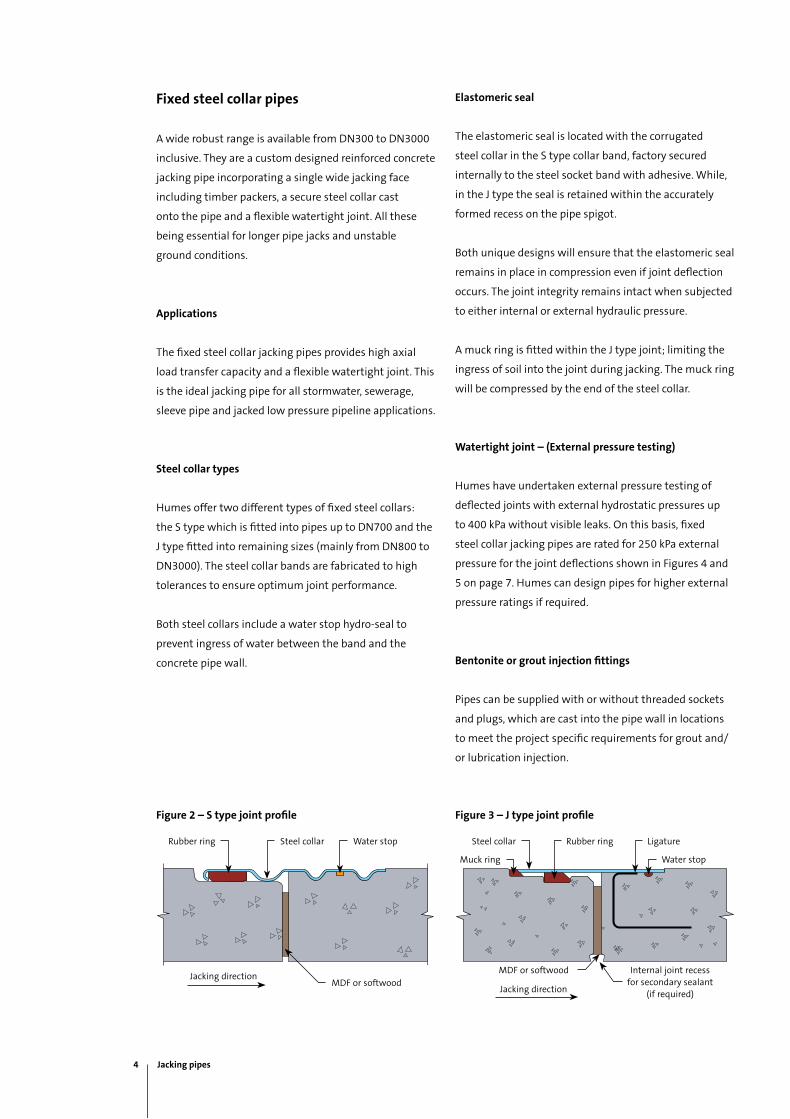
Figure 2 – S type joint profile Figure 3 – J type joint profile
Elastomeric seal
The elastomeric seal is located with the corrugated
steel collar in the S type collar band, factory secured
internally to the steel socket band with adhesive. While,
in the J type the seal is retained within the accurately
formed recess on the pipe spigot.
Both unique designs will ensure that the elastomeric seal
remains in place in compression even if joint deflection
occurs. The joint integrity remains intact when subjected
to either internal or external hydraulic pressure.
A muck ring is fitted within the J type joint; limiting the
ingress of soil into the joint during jacking. The muck ring
will be compressed by the end of the steel collar.
Watertight joint – (External pressure testing)
Humes have undertaken external pressure testing of
deflected joints with external hydrostatic pressures up
to 400 kPa without visible leaks. On this basis, fixed
steel collar jacking pipes are rated for 250 kPa external
pressure for the joint deflections shown in Figures 4 and
5 on page 7. Humes can design pipes for higher external
pressure ratings if required.
Bentonite or grout injection fittings
Pipes can be supplied with or without threaded sockets
and plugs, which are cast into the pipe wall in locations
to meet the project specific requirements for grout and/
or lubrication injection.
4 Jacking pipes
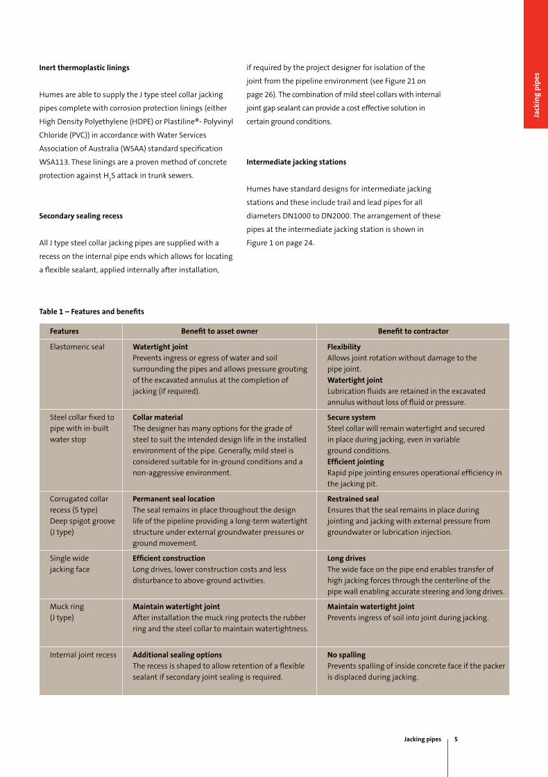
Table 1 – Features and benefits
Features Benefit to asset owner Benefit to contractor
Elastomeric seal Watertight joint
Prevents ingress or egress of water and soil
surrounding the pipes and allows pressure grouting
of the excavated annulus at the completion of
jacking (if required).
Flexibility
Allows joint rotation without damage to the
pipe joint.
Watertight joint
Lubrication fluids are retained in the excavated
annulus without loss of fluid or pressure.
Steel collar fixed to
pipe with in-built
water stop
Collar material
The designer has many options for the grade of
steel to suit the intended design life in the installed
environment of the pipe. generally, mild steel is
considered suitable for in-ground conditions and a
non-aggressive environment.
Secure system
Steel collar will remain watertight and secured
in place during jacking, even in variable
ground conditions.
Efficient jointing
Rapid pipe jointing ensures operational efficiency in
the jacking pit.
Corrugated collar
recess (S type)
Deep spigot groove
(J type)
Permanent seal location
The seal remains in place throughout the design
life of the pipeline providing a long-term watertight
structure under external groundwater pressures or
ground movement.
Restrained seal
Ensures that the seal remains in place during
jointing and jacking with external pressure from
groundwater or lubrication injection.
Single wide
jacking face
Efficient construction
Long drives, lower construction costs and less
disturbance to above-ground activities.
Long drives
The wide face on the pipe end enables transfer of
high jacking forces through the centerline of the
pipe wall enabling accurate steering and long drives.
muck ring
(J type)
Maintain watertight joint
After installation the muck ring protects the rubber
ring and the steel collar to maintain watertightness.
Maintain watertight joint
Prevents ingress of soil into joint during jacking.
internal joint recess Additional sealing options
The recess is shaped to allow retention of a flexible
sealant if secondary joint sealing is required.
No spalling
Prevents spalling of inside concrete face if the packer
is displaced during jacking.
Inert thermoplastic linings
Humes are able to supply the J type steel collar jacking
pipes complete with corrosion protection linings (either
High Density Polyethylene (HDPE) or Plastiline®- Polyvinyl
Chloride (PVC)) in accordance with Water Services
Association of Australia (WSAA) standard specification
WSA113. These linings are a proven method of concrete
protection against H2S attack in trunk sewers.
Secondary sealing recess
All J type steel collar jacking pipes are supplied with a
recess on the internal pipe ends which allows for locating
a flexible sealant, applied internally after installation,
if required by the project designer for isolation of the
joint from the pipeline environment (see Figure 21 on
page 26). The combination of mild steel collars with internal
joint gap sealant can provide a cost effective solution in
certain ground conditions.
Intermediate jacking stations
Humes have standard designs for intermediate jacking
stations and these include trail and lead pipes for all
diameters DN1000 to DN2000. The arrangement of these
pipes at the intermediate jacking station is shown in
Figure 1 on page 24.
Jacking pipes 5
Jack
ing
pip
es
Optimal strength
Humes fixed collar jacking pipes, both with S and J type
collar, are designed with steel reinforcement placed for
optimal strength, which combined with the strength and
durability of Humes concrete pipes, provides an excellent
jacking pipe. Steel reinforced concrete jacking pipes are
capable of withstanding higher jacking loads.
The jacking load capacity of standard pipes for a range
of joint deflections is illustrated in Figures 4 and 5 on the
following page. Pipes with higher jacking loads and/or
joint deflections can be designed for specific projects.
Jacking design and forces
The Concrete Pipe Association of Australasia (CPAA)
publication, Jacking Design Guidelines is a recommended
guide to calculate and define jacking forces. The guide
can be downloaded by visiting;
www.cpaa.asn.au/CPAA-Online-Shop.html
Jacking forces and lateral displacement off line and
level have to be recorded at regular intervals of jacking
distance (not exceeding 200 mm or every 90 seconds).
Ensure that jacking forces are maintained within the
limits specified in Figures 4 and 5 on the following
page. if circumstances cause a jacking force/deflection
combination outside of these limits, hold the jacking
operation and contact Humes for assistance.
6 Jacking pipes
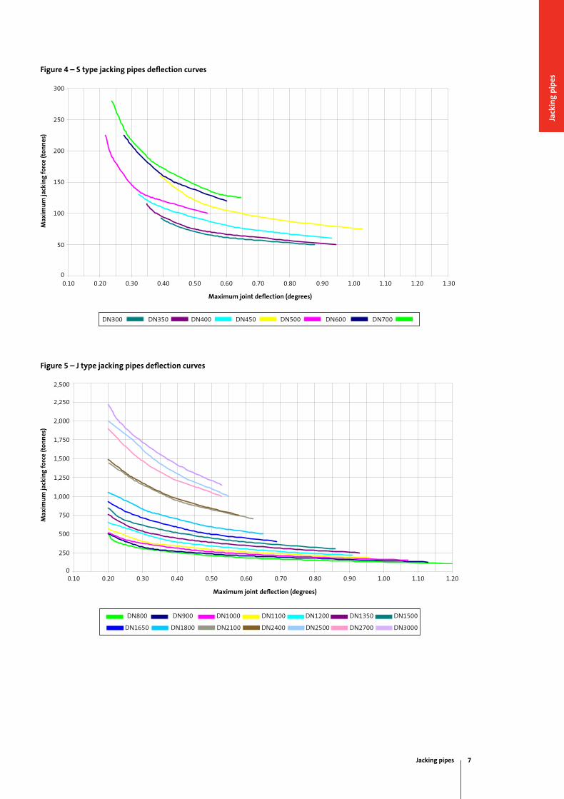
Figure 4 – S type jacking pipes deflection curves
Figure 5 – J type jacking pipes deflection curves
Max
imu
m ja
ckin
g fo
rce
(ton
nes
)
300
250
200
150
100
0.90 1.00 1.10 1.20 1.30
50
0
����������������������
�
��
���
���
���
���
���
����� ����� ����� ����� ����� ����� ����� ����� ����� ����� ����� ����� �����
����������������������������������
����
����
����
����
����
��������
��
����� ����� ����� ����� ����� ����� �����
Maximum joint deflection (degrees)
0.10 0.20 0.30 0.40 0.50 0.60 0.70 0.80
DN700DN600DN500DN450DN400DN350DN300
DN800 DN900 DN1000
DN1650 DN1800 DN2100 DN2400 DN2500 DN2700 DN3000
DN1100 DN1200 DN1350 DN1500
J Series Jacking Pipes
0
250
500
750
1000
1250
1500
1750
2000
2250
2500
0.10 0.20 0.30 0.40 0.50 0.60 0.70 0.80 0.90 1.00 1.10 1.20
Maximum Joint De�ection (Degrees)
Max
imum
Jack
ing
Forc
e (T
onne
s)
DN800 DN900 DN1000 DN1100 DN1200 DN1350 DN1500 DN1650 DN1800 DN2100 DN2400 DN2500
DN2700 DN3000
Max
imu
m ja
ckin
g fo
rce
(ton
nes
)
Maximum joint deflection (degrees)
2,500
2,250
2,000
1,750
1,500
1,250
1,000
750
500
250
0.10 0.20 0.30 0.40 0.50 0.60 0.70 0.80 0.90 1.00 1.100
1.20
Jacking pipes 7
Jack
ing
pip
es
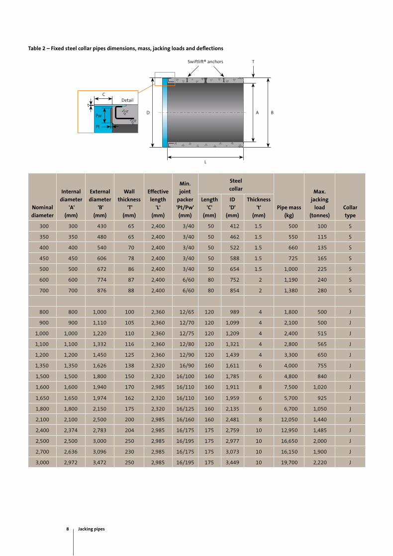
Table 2 – Fixed steel collar pipes dimensions, mass, jacking loads and deflections
Nominal
diameter
Internal
diameter
'A'
(mm)
External
diameter
'B'
(mm)
Wall
thickness
'T'
(mm)
Effective
length
'L'
(mm)
Min.
joint
packer
'Pt/Pw'
(mm)
Steel
collar
Pipe mass
(kg)
Max.
jacking
load
(tonnes)
Collar
type
Length
'C'
(mm)
ID
'D'
(mm)
Thickness
't'
(mm)
300 300 430 65 2,400 3/40 50 412 1.5 500 100 S
350 350 480 65 2,400 3/40 50 462 1.5 550 115 S
400 400 540 70 2,400 3/40 50 522 1.5 660 135 S
450 450 606 78 2,400 3/40 50 588 1.5 725 165 S
500 500 672 86 2,400 3/40 50 654 1.5 1,000 225 S
600 600 774 87 2,400 6/60 80 752 2 1,190 240 S
700 700 876 88 2,400 6/60 80 854 2 1,380 280 S
800 800 1,000 100 2,360 12/65 120 989 4 1,800 500 J
900 900 1,110 105 2,360 12/70 120 1,099 4 2,100 500 J
1,000 1,000 1,220 110 2,360 12/75 120 1,209 4 2,400 515 J
1,100 1,100 1,332 116 2,360 12/80 120 1,321 4 2,800 565 J
1,200 1,200 1,450 125 2,360 12/90 120 1,439 4 3,300 650 J
1,350 1,350 1,626 138 2,320 16/90 160 1,611 6 4,000 755 J
1,500 1,500 1,800 150 2,320 16/100 160 1,785 6 4,800 840 J
1,600 1,600 1,940 170 2,985 16/110 160 1,911 8 7,500 1,020 J
1,650 1,650 1,974 162 2,320 16/110 160 1,959 6 5,700 925 J
1,800 1,800 2,150 175 2,320 16/125 160 2,135 6 6,700 1,050 J
2,100 2,100 2,500 200 2,985 16/160 160 2,481 8 12,050 1,440 J
2,400 2,374 2,783 204 2,985 16/175 175 2,759 10 12,950 1,485 J
2,500 2,500 3,000 250 2,985 16/195 175 2,977 10 16,650 2,000 J
2,700 2,636 3,096 230 2,985 16/175 175 3,073 10 16,150 1,900 J
3,000 2,972 3,472 250 2,985 16/195 175 3,449 10 19,700 2,220 J
ADPw
Pt
C
t
L
B
TSwiftlift® anchors
Detail
8 Jacking pipes
Loose steel collar pipes
Humes offer two types of loose steel collar SRCP jacking
pipes, butt joint and in-wall joint. They are available from
DN300 to DN3000 (standard range DN300 to DN2100).
The steel collar is not attached to the pipe (cast with)
but rather is fitted onto the pipe before installation. The
collars can be supplied by either Humes or the contractor.
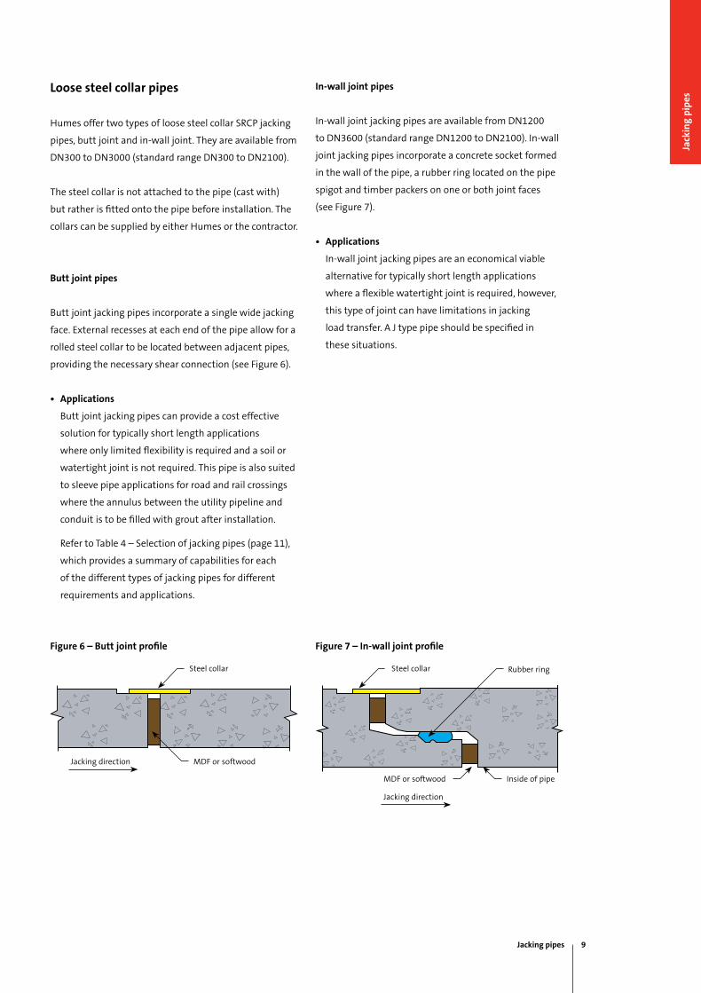
Butt joint pipes
Butt joint jacking pipes incorporate a single wide jacking
face. External recesses at each end of the pipe allow for a
rolled steel collar to be located between adjacent pipes,
providing the necessary shear connection (see Figure 6).
• Applications
Butt joint jacking pipes can provide a cost effective
solution for typically short length applications
where only limited flexibility is required and a soil or
watertight joint is not required. This pipe is also suited
to sleeve pipe applications for road and rail crossings
where the annulus between the utility pipeline and
conduit is to be filled with grout after installation.
Refer to Table 4 – Selection of jacking pipes (page 11),
which provides a summary of capabilities for each
of the different types of jacking pipes for different
requirements and applications.
Figure 6 – Butt joint profile Figure 7 – In-wall joint profile
In-wall joint pipes
in-wall joint jacking pipes are available from DN1200
to DN3600 (standard range DN1200 to DN2100). in-wall
joint jacking pipes incorporate a concrete socket formed
in the wall of the pipe, a rubber ring located on the pipe
spigot and timber packers on one or both joint faces
(see Figure 7).
• Applications
in-wall joint jacking pipes are an economical viable
alternative for typically short length applications
where a flexible watertight joint is required, however,
this type of joint can have limitations in jacking
load transfer. A J type pipe should be specified in
these situations.
Steel collar Steel collar
Jacking pipes 9
Jack
ing
pip
es
Selection of jacking pipes
The most basic requirements for all jacking pipes is
that they must be capable of supporting the excavation
(earth and traffic loads), transferring axial load, providing
a shear connection between adjacent pipes and joint
flexibility that allows for each pipe to follow the path
excavated in front of the shield.
in addition, jacking pipes may need to prevent ingress of
surrounding soil, groundwater, lubricants or grouts and
provide a joint capable of withstanding internal pressure
in sewerage or pressure pipeline applications.
Jacking pipes must meet both the needs of the
contractor and asset owner who is usually represented
by the pipeline designer. Table 4 opposite provides a
summary of the capabilities of each of our types of
jacking pipes for different requirements and applications.
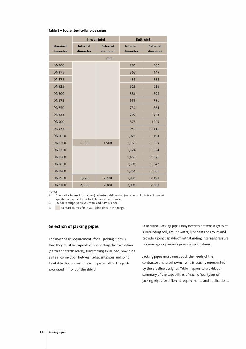
Table 3 – Loose steel collar pipe range
Nominal
diameter
In-wall joint Butt joint
Internal
diameter
External
diameter
Internal
diameter
External
diameter
mm
DN300 280 362
DN375 363 445
DN475 438 534
DN525 518 616
DN600 586 698
DN675 653 781
DN750 730 864
DN825 790 946
DN900 875 1029
DN975 951 1,111
DN1050 1,026 1,194
DN1200 1,200 1,500 1,163 1,359
DN1350 1,324 1,524
DN1500 1,452 1,676
DN1650 1,596 1,842
DN1800 1,756 2,006
DN1950 1,920 2,220 1,930 2,198
DN2100 2,088 2,388 2,096 2,388
Notes:1. Alternative internal diameters (and external diameters) may be available to suit project
specific requirements, contact Humes for assistance.2. Standard range is equivalent to load class 4 pipes.
3. Contact Humes for in-wall joint pipes in this range.
10 Jacking pipes
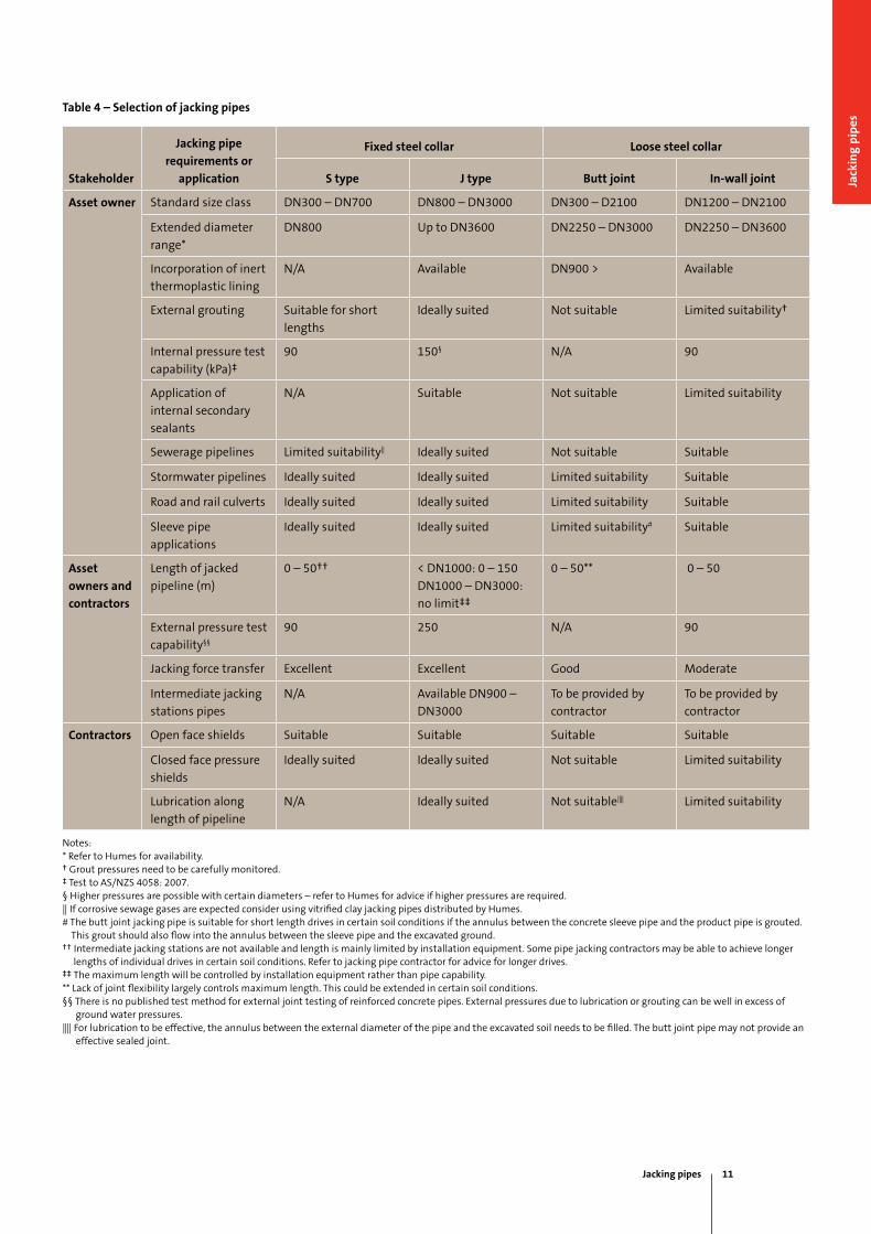
Table 4 – Selection of jacking pipes
Stakeholder
Jacking pipe
requirements or
application
Fixed steel collar Loose steel collar
S type J type Butt joint In-wall joint
Asset owner Standard size class DN300 – DN700 DN800 – DN3000 DN300 – D2100 DN1200 – DN2100
Extended diameter
range*
DN800 up to DN3600 DN2250 – DN3000 DN2250 – DN3600
incorporation of inert
thermoplastic lining
N/A Available DN900 > Available
External grouting Suitable for short
lengths
ideally suited Not suitable Limited suitability†
internal pressure test
capability (kPa)‡
90 150§ N/A 90
Application of
internal secondary
sealants
N/A Suitable Not suitable Limited suitability
Sewerage pipelines Limited suitability|| ideally suited Not suitable Suitable
Stormwater pipelines ideally suited ideally suited Limited suitability Suitable
Road and rail culverts ideally suited ideally suited Limited suitability Suitable
Sleeve pipe
applications
ideally suited ideally suited Limited suitability# Suitable
Asset
owners and
contractors
Length of jacked
pipeline (m)
0 – 50†† < DN1000: 0 – 150
DN1000 – DN3000:
no limit‡‡
0 – 50** 0 – 50
External pressure test
capability§§
90 250 N/A 90
Jacking force transfer Excellent Excellent good moderate
intermediate jacking
stations pipes
N/A Available DN900 –
DN3000
To be provided by
contractor
To be provided by
contractor
Contractors Open face shields Suitable Suitable Suitable Suitable
Closed face pressure
shields
ideally suited ideally suited Not suitable Limited suitability
Lubrication along
length of pipeline
N/A ideally suited Not suitable|||| Limited suitability
Notes:* Refer to Humes for availability.† grout pressures need to be carefully monitored.‡ Test to AS/NZS 4058: 2007.§ Higher pressures are possible with certain diameters – refer to Humes for advice if higher pressures are required.|| if corrosive sewage gases are expected consider using vitrified clay jacking pipes distributed by Humes.# The butt joint jacking pipe is suitable for short length drives in certain soil conditions if the annulus between the concrete sleeve pipe and the product pipe is grouted. This grout should also flow into the annulus between the sleeve pipe and the excavated ground.†† intermediate jacking stations are not available and length is mainly limited by installation equipment. Some pipe jacking contractors may be able to achieve longer lengths of individual drives in certain soil conditions. Refer to jacking pipe contractor for advice for longer drives.‡‡ The maximum length will be controlled by installation equipment rather than pipe capability. ** Lack of joint flexibility largely controls maximum length. This could be extended in certain soil conditions.§§ There is no published test method for external joint testing of reinforced concrete pipes. External pressures due to lubrication or grouting can be well in excess of ground water pressures. |||| For lubrication to be effective, the annulus between the external diameter of the pipe and the excavated soil needs to be filled. The butt joint pipe may not provide an effective sealed joint.
Jacking pipes 11
Jack
ing
pip
es
Load class
Jacking pipes, as opposed to pipes laid in open
excavations, are subjected to both jacking forces,
external earth loads and life loads (permanent loads)
and all of these have to be considered when specifying
the pipes.
The effect of the jacking force on the pipe barrel is
small on account of the high compressive strength of
the concrete. The joint, however, must be considered
because the joint cross-section is smaller, as a rule, than
that of the barrel and the jacking force is transferred
eccentrically across the joint.
The external earth load on the barrel is equal to or
smaller than the trench load on a pipe bedded in a
trench of same width as the excavation (i.e. the outside
diameter of the pipe plus a margin for over-excavation).
The jacking method of installation, therefore, is very
efficient from an external load point of view since the
external earth load is smaller than both trench and
embankment load on pipes of the same diameter under
the same height of fill.
As such a minimum Class 4 pipe is usually recommended
although in some short length drives a Class 3 may
be suitable. The Class 4 pipe to Australian Standard
AS/NZS 4058: 2007 has very similar strength
requirements to load classes specified for jacking pipes
in European and Japanese Standards.
AS/NZS 4058: 2007 outlines the technique for
determining the permanent vertical loads acting on
pipes installed using pipe jacking. The jacking pipe
is installed underground into undisturbed natural
ground where the soil’s natural cohesion contributes to
arching over the pipe. Where the calculation includes
the effects of arching due to soil cohesion extensive soil
investigations should be carried out to determine the
appropriate design soil properties.
The jacking installation results in a recommended
bedding factor between two and three that is used to
determine the minimum suitable pipe class required due
to permanent loads.
The higher value is recommended when the annulus
between the pipe and ground is grouted. grouting
of this annulus with a suitable cementitious grout is
recommended in most installations as any voids could
create a drainage path external to the pipeline which in
turn could lead to soil erosion, lowering of ground water
tables and, in aggressive soil conditions, an increased risk
of corrosion of pipe materials.
The axial loading from the pipe jacking is not directly
included in the selection of the pipe load class. Timber
packers are placed between the jacking faces of the
concrete pipes to avoid high stresses that could result
from direct concrete to concrete contact. The axial load
capacity of the concrete pipe is determined based on
the minimum pipe wall thickness, concrete strength,
properties of the timber packers and the deflections that
can be expected at pipe joints during installation.
The allowable jacking forces and associated maximum
joint deflections are calculated in accordance with
the Concrete Pipe Association of Australasia (CPAA)
publication, Jacking Design Guidelines.
Source: Jacking Design guidelines, Concrete Pipe Association of Australasia.
Jacking design and forces
The CPAA publication, Jacking Design Guidelines, is a
recommended guide to calculate and define jacking
forces. The guide can be downloaded by visiting;
www.cpaa.asn.au/CPAA-Online-Shop.html
Jacking force and lateral displacement off line and
level have to be recorded at regular intervals of jacking
distance (not exceeding 200 mm or every 90 seconds).
Ensure that jacking forces are maintained within the
specified limits. if circumstances cause a jacking force/
deflection combination outside of these limits, hold the
jacking operation and contact Humes for assistance.
12 Jacking pipes
Vitrified clay pipes
Humes vitrified clay jacking pipes are manufactured by
STEiNZEug-KERAmO (STEiNZEug Abwassersysteme
gmbH) and inspected in accordance with the European
standard for vitrified clay pipes, fittings and joints for
drains and sewers - EN 295.
Features and benefits
Watertightness
The joints are tested in accordance with EN 295, which
means that they are guaranteed to be watertight at
0.5 bar, including the angular deflections and radial
loads specified in the standard. They are also tested
in accordance with ZPWN 2951 and ATV A142, with
guaranteed watertightness at 2.4 bar. Watertightness
is also tested at an external pressure of 6 bar, which
provides a high level of security against penetration of
soil slurries and bentonite.
Corrosion resistance
Vitrified clay material is resistant to all types of chemicals
over the entire wall thickness. The resistance of the
vitrified clay material and seals is tested using chemicals,
including sulphuric acid at pH 0 and NaOH at pH 14, in
conformance with EN 295 and ZPWN 295.
High mechanical strength
Vitrified clay jacking pipes generally have greater wall
thicknesses than corresponding standard vitrified clay
sewer pipes, that results in high crown pressure ratings
and high resistance to ground and traffic loads.
1. ZPWN 295 is an internal manufacturer standard of STEiNZEug-KERAmO.
Strength in the length direction is the most important
factor for jacking pipes, because they must withstand the
high jacking forces necessary to overcome the resistance
of the cutting face and the external pipe surface.
According to the EN 295 standard, the longitudinal
compressive strength of the surfaces that transfer the
force between pipe sections must be at least 75 N/mm².
STEiNZEug-KERAmO guarantees a value of at least
100 N/mm². That is higher than the values stated for
other types of current jacking material. it allows very
high jacking forces to be used, although this capability is
only partially utilised in practice. The glazed outer surface
of the pipe strongly reduces friction between the pipe
and the surrounding soil.
High abrasion resistance
Vitrified clay has high abrasion resistance, which
is equally true for the glaze and the rest of the
wall. Abrasion values encountered in the tests are
approximately 0.08 mm, which is much lower than
the typical abrasion values of 0.2 mm to 0.5 mm after
100,000 load cycles measured using the Darmstadt test
as specified in the EN 295 standard or the maximum
value of 0.25 mm in the ZPWN 295 standard. Abrasion
does not accelerate even with extended load cycles, such
as up to 400,000, in contrast to what is often suggested
in data sheets for competitive materials. The depth of
abrasion remains limited to 0.3 - 0.8 mm after 400,000
cycles. Compared with the large wall thicknesses of
vitrified clay jacking pipes, that represents a negligible
loss of wall thickness.
Jacking pipes 13
Jack
ing
pip
es
Resistance to high-pressure cleaning
The requirement included in the ZPWN 295 standard
is met (resistance with regard to a standardised
maintenance cleaning test at 120 bar and a deblocking
test at 340 bar). Here again, vitrified clay scores
considerably better than many other types of material.
Temperature resistance
Pipes and seals are tested at up to 70 °C. Vitrified clay
pipes can tolerate even higher temperatures.
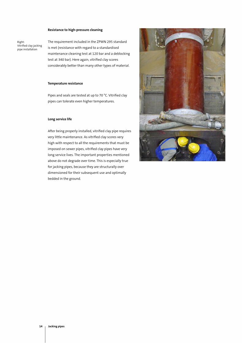
Long service life
After being properly installed, vitrified clay pipe requires
very little maintenance. As vitrified clay scores very
high with respect to all the requirements that must be
imposed on sewer pipes, vitrified clay pipes have very
long service lives. The important properties mentioned
above do not degrade over time. This is especially true
for jacking pipes, because they are structurally over
dimensioned for their subsequent use and optimally
bedded in the ground.
Right: Vitrified clay jacking pipe installation
14 Jacking pipes
Product range
The entire range of vitrified clay jacking pipes DN200 to
DN1200 are fitted with a stainless steel coupling which
has a high chrome and nickel content and a relatively
significant molybdenum content. This coupling is highly
resistant to corrosion in aggressive soils (acids, chlorides
and halogens).
Two different types of stainless steel couplings are used,
Type 1 and Type 2.
DN200 to DN300 with Type 1 stainless steel coupling
• The moulded elastomer seal is integrated into the ring.
• The packing ring, which transmits the jacking force is
made from elastomer for diameters up to DN300 and
forms a unit with the moulded sealing ring.
• Pipes are sawn at both ends to yield parallel end faces.
• The spigot ends are milled. The precision ground
spigots as for larger dimension jacking pipes permit a
safe internal working pressure of 2.4 bar.
• The sealing capabilities of the coupler due to its special
design not only guarantees joint integrity, but ensures
full protection from the ingress of matter during the
jacking process.
DN400 to DN1200 with Type 2 stainless steel coupling
• Themouldedrubbersealisintegratedina
milled groove.
• Thepackingring,whichtransmitsthejackingforce,
is made from particle board and is prefitted to
the coupling.
• Pipesaresawnandmilledatbothendstoyieldparallel
end faces.
• FordiametersDN600andaboveaclamping
(prestressing) ring is fitted at each spigot end. This ring
increases the permissible jacking force and provides
additional protection in case of poorly controlled
steering motions during jacking or when angular
deflections occur due to variations in soil conditions.
• Intermediatere-usablejackingstationscanbeused
with diameters of DN600 and above. This is advisable
for long jacking distances and when jacking forces
exceeding the specified limits are anticipated. The
intermediate jacking stations are coupled to the spigot
ends of the pipes and recovered in the receival pit or an
intermediate shaft.The trenchless mode of construction
12
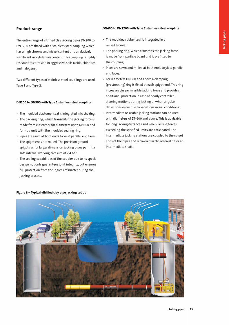
At the present time two remote steered meth-ods for the construction of underground sew-ers are in use. These two methods aredescribed below in accordance with ATVworking sheet A 125 - microtunnelling:
Shield pipe jacking (Slurry system)Jacking of casing or media pipes is realisedwith simultaneous full cross-section removal ofthe soil from the working face, counter bal-anced by mechanical and hydraulic loads.Surveying is carried out with a laser beam.Changes in direction are executed with the aidof a cutter head able to be swivelled hydrauli-cally. The spoil is continuously removed, usually bymeans of a hydraulic system. The slurry medi-um is recirculated through a pipe systemplaced inside the vitrified clay pipes, which islengthened each time a new pipe is inserted.The pressure required for the slurry medium iscontrolled by a supply and discharge mecha-nism. If water is used as a slurry medium, it isnormally adequate to use settlement basins. If
bentonite suspensions are used, special sandremoval equipment is used. The drive for thecutting head and for the steering cylinders arelocated in the jacking shield. In general thismethod is used for pipes of external diametersup to 1850 mm and manhole to manholelengths of up to 250 m in earth and rock withand without ground water, the particular man-hole to manhole length possible depending onthe nominal size of the pipes.The cutting wheel to be used on the cutterhead is selected on the basis of the composi-tion of earth. Use of the correct tools selectedin accordance with the consistency of the soiland the anticipated size of the stones enablesthe rate of microtunnelling to be optimised.Cutter heads for rock can be used from DN500. The expert reports on the soil, which areessential for microtunnelling, can be preparedin accordance with DIN 18319, VOB part C. Areprint "Opportunities and limits for microtun-nelling taking into account the excavatingtools" can be obtained from STEINZEUG | KERAMO.
Figure 8 – Typical vitrified clay pipe jacking set up
Jacking pipes 15
Jack
ing
pip
es
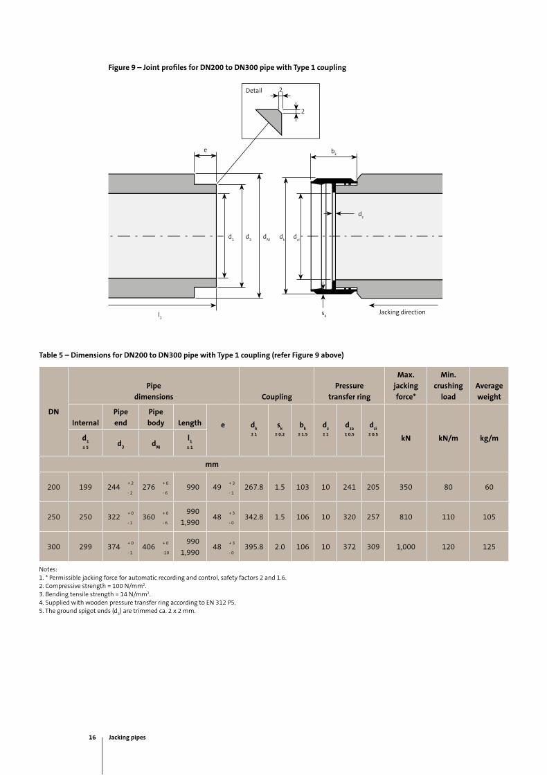
Figure 9 – Joint profiles for DN200 to DN300 pipe with Type 1 coupling
Table 5 – Dimensions for DN200 to DN300 pipe with Type 1 coupling (refer Figure 9 above)
DN
Pipe
dimensions Coupling
Pressure
transfer ring
Max.
jacking
force*
Min.
crushing
load
Average
weight
Internal
Pipe
end
Pipe
body Length e dk
± 1
sk
± 0.2
bk
± 1.5
dz
± 1
dza
± 0.5
dzi
± 0.5kN kN/m kg/md
1± 5
d3
dM
l1
± 1
mm
200 199 244+ 2
276+ 0
990 49+ 3
267.8 1.5 103 10 241 205 350 80 60- 2 - 6 - 1
250 250 322+ 0
360+ 0 990
1,99048
+ 3342.8 1.5 106 10 320 257 810 110 105
- 1 - 6 - 0
300 299 374+ 0
406+ 0 990
1,99048
+ 3395.8 2.0 106 10 372 309 1,000 120 125
- 1 -10 - 0
Notes:1. * Permissible jacking force for automatic recording and control, safety factors 2 and 1.6.2. Compressive strength = 100 N/mm2.3. Bending tensile strength = 14 N/mm2.4. Supplied with wooden pressure transfer ring according to EN 312 P5.5. The ground spigot ends (d
3) are trimmed ca. 2 x 2 mm.
l1
Jacking directionsk
dz
e
2
2
d1
bk
d3
dm
dk
dzi
Detail
16 Jacking pipes
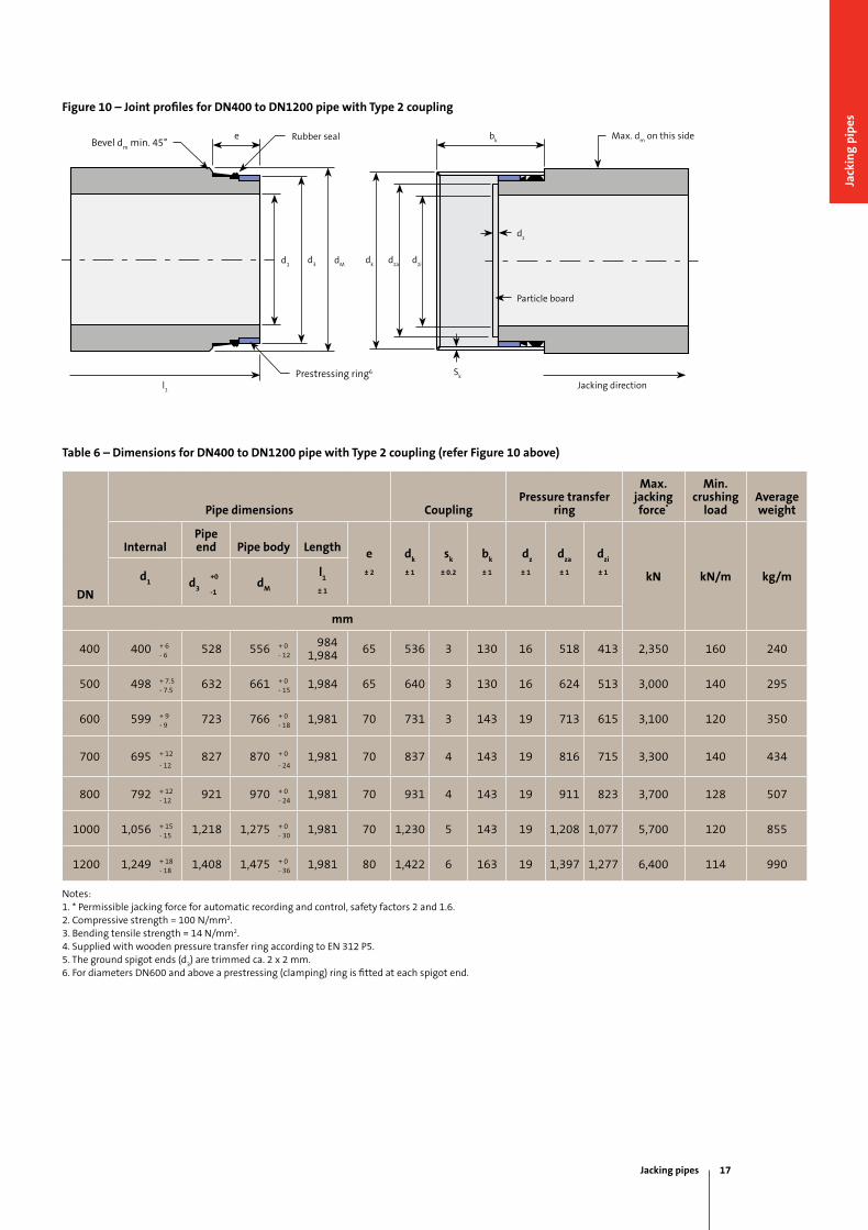
Figure 10 – Joint profiles for DN400 to DN1200 pipe with Type 2 coupling
Table 6 – Dimensions for DN400 to DN1200 pipe with Type 2 coupling (refer Figure 10 above)
DN
Pipe dimensions CouplingPressure transfer
ring
Max. jacking force*
Min. crushing
loadAverage weight
InternalPipe end Pipe body Length e
± 2
dk
± 1
sk
± 0.2
bk
± 1
dz
± 1
dza
± 1
dzi
± 1 kN kN/m kg/md1 d
3
+0d
M
l1
± 1-1
mm
400 400 + 6 528 556 + 0 984 1,984 65 536 3 130 16 518 413 2,350 160 240
- 6 - 12
500 498 + 7.5 632 661 + 0 1,984 65 640 3 130 16 624 513 3,000 140 295- 7.5 - 15
600 599 + 9 723 766 + 0 1,981 70 731 3 143 19 713 615 3,100 120 350- 9 - 18
700 695 + 12 827 870 + 0 1,981 70 837 4 143 19 816 715 3,300 140 434- 12 - 24
800 792 + 12 921 970 + 0 1,981 70 931 4 143 19 911 823 3,700 128 507- 12 - 24
1000 1,056 + 15 1,218 1,275 + 0 1,981 70 1,230 5 143 19 1,208 1,077 5,700 120 855- 15 - 30
1200 1,249 + 18 1,408 1,475 + 0 1,981 80 1,422 6 163 19 1,397 1,277 6,400 114 990- 18 - 36
Notes:1. * Permissible jacking force for automatic recording and control, safety factors 2 and 1.6.2. Compressive strength = 100 N/mm2.3. Bending tensile strength = 14 N/mm2.4. Supplied with wooden pressure transfer ring according to EN 312 P5.5. The ground spigot ends (d
3) are trimmed ca. 2 x 2 mm.
6. For diameters DN600 and above a prestressing (clamping) ring is fitted at each spigot end.
max. dm
on this side
l1
Jacking direction
Particle board
Rubber seal
dz
Sk
e
d1
bk
d3 d
md
kd
zad
zi
Bevel dm
min. 45°
Prestressing ring6
Jacking pipes 17
Jack
ing
pip
es
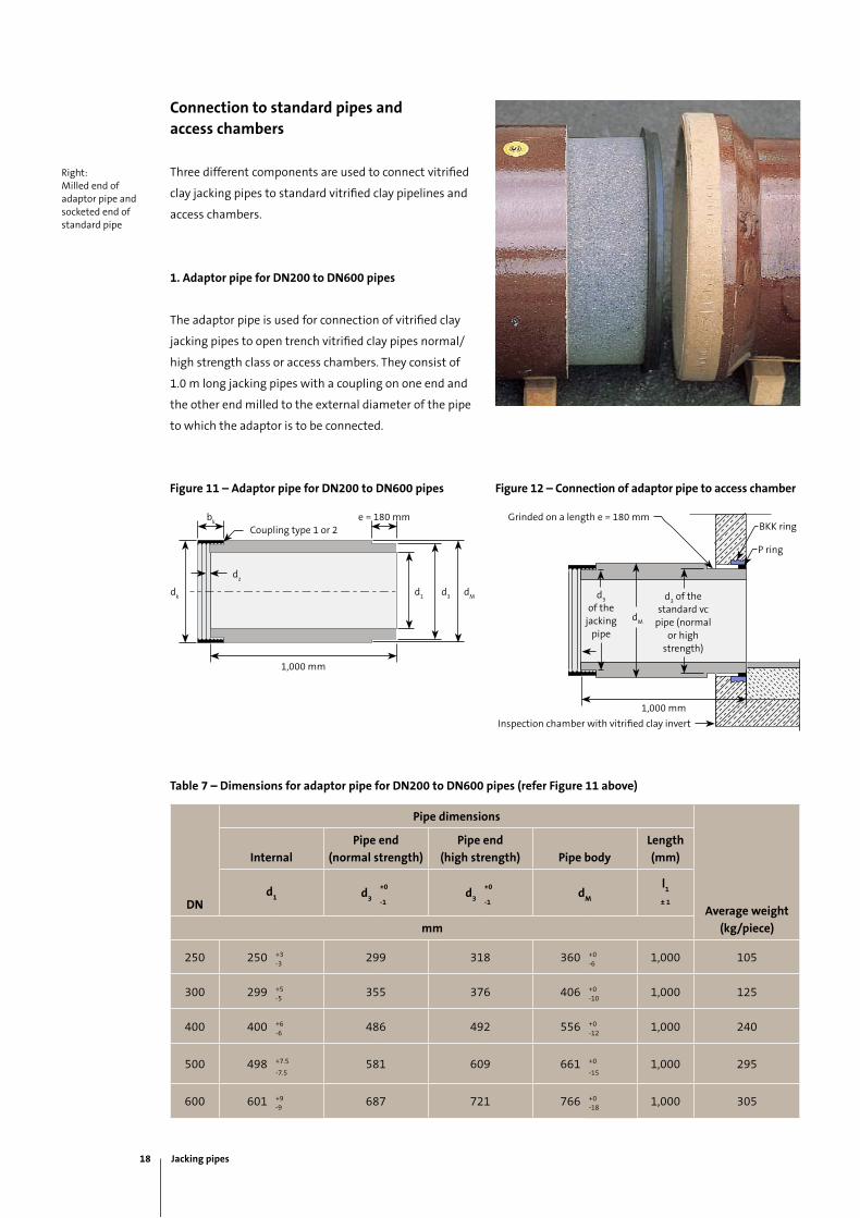
Connection to standard pipes and access chambers
Three different components are used to connect vitrified
clay jacking pipes to standard vitrified clay pipelines and
access chambers.
1. Adaptor pipe for DN200 to DN600 pipes
The adaptor pipe is used for connection of vitrified clay
jacking pipes to open trench vitrified clay pipes normal/
high strength class or access chambers. They consist of
1.0 m long jacking pipes with a coupling on one end and
the other end milled to the external diameter of the pipe
to which the adaptor is to be connected.
Figure 11 – Adaptor pipe for DN200 to DN600 pipes
85
Connections to standard pipes and shafts
Rocker pipe for connection of jacking pipesto standard pipes with two different outsidediametersFor the connection to chambers or v.c. pipesnormal or high strengthVitrified clay adaptors are used for the transi-tion to standard and high load series socketedpipes. The adaptors consist of 1.0 m longjacking pipes with a coupling on one end andthe other end milled to the external diameter ofthe pipe to which the adaptor should be con-nected. With the aid of a P-ring, the transitionto "K" or "S" jointed pipes (in accordance withjointing system C) can be created.A further way of achieving the transition from avitrified clay jacking pipe to a vitrified clay sock-eted pipe is provided by the use of an bush ringto equal out the different diameters. Then, with
the aid of the metal banded flexible coupling (M-seal type 2B), a watertight and reliable connec-tion is created. The external diameters of thecomponents to be connected must be deter-mined precisely prior to ordering the bushes.
Bush types according to outside diameter dif-ferences. To combine with M seals.
Pipe Diameter Nominal Averagelength weight
DN d1 d3 d3 dM l1+0/–1 +0/–1 max. +/–1 kg/pc
(N) (H)
250 +/–3 299 318 360 +0/-6 1000 105
300 +/–5 355 376 406 +0/-10 1000 125
400 +/–6 486 492 556 +0/-12 1000 240
500 +/–7,5 581 609 661 +0/-15 1000 295
600 +/–9 687 721 766 +0/-18 1000 350
Dimensions in mm; technical changes reserved
Coupling type 1 or 2
In the standard and high load series, transitionsto socketed pipes with "K" and "S" joints inaccordance with system C can be achieved withthe aid of the adaptor ring (P-ring).
DN 250 - DN 600 adaptorOptionally with coupling type 1 or to.
Optionally with d3 dimension for standard or high load pipes.
M-seal (type 2B)
Jacking pipe DN 500 covered steel coupling or V4A
Standard v.c. pipe
Cut off milled spigotBush of rubber elastomer; b = 80 mm(thickness must be matched to the dif-ference to be bridged)
21
Outsite diameter(mm)
thickness (mm)4 8 12 16 24 32
160 to 199 x x x x x200 to 299 x x x x x x300 to 1399 x x x x x
DN(mm)
External diameter
dM
Metal banded flexible coupling type 2Bv.c. normal strength
class (N)v.c. high strength
class (H)
150 213 190-215 or 200-225
200 276225-250 with
bush 16 mm thick265-290
300 406335-360 with
bush 24 mm thick385-410
400 556460-490 with
bush 32 mm thick495-525 or 510-540 or
520-550
500 661570-600 with bush
40 mm thick (16 and 24)610-640 or 630-660 or
650-680
600 766 685-715 730-760 or 750-780
700 870 800-830 or 820-850 860-690
800 970 900-930 or 920-950 970-999
Width metal banded flexible coupling type 2B DN 150 and DN 200: 150 mmWidth metal banded flexible coupling type 2B = DN 250: 190 mm
Right: milled end of adaptor pipe and socketed end of standard pipe
Coupling type 1 or 2
1,000 mm
bk
dk
d1
d3
dm
dz
e = 180 mm
Table 7 – Dimensions for adaptor pipe for DN200 to DN600 pipes (refer Figure 11 above)
DN
Pipe dimensions
Average weight
(kg/piece)
Internal
Pipe end
(normal strength)
Pipe end
(high strength) Pipe body
Length
(mm)
d1 d
3
+0d
3
+0d
M
l1
± 1-1 -1
mm
250 250 +3 299 318 360 +0 1,000 105-3 -6
300 299 +5 355 376 406 +0 1,000 125-5 -10
400 400 +6 486 492 556 +0 1,000 240-6 -12
500 498 +7.5 581 609 661 +0 1,000 295-7.5 -15
600 601 +9 687 721 766 +0 1,000 305-9 -18
Figure 12 – Connection of adaptor pipe to access chamber
grinded on a length e = 180 mmBKK ring
P ring
inspection chamber with vitrified clay invert
d3
of the jacking
pipe
d3 of the
standard vc pipe (normal
or high strength)
dm
1,000 mm
18 Jacking pipes
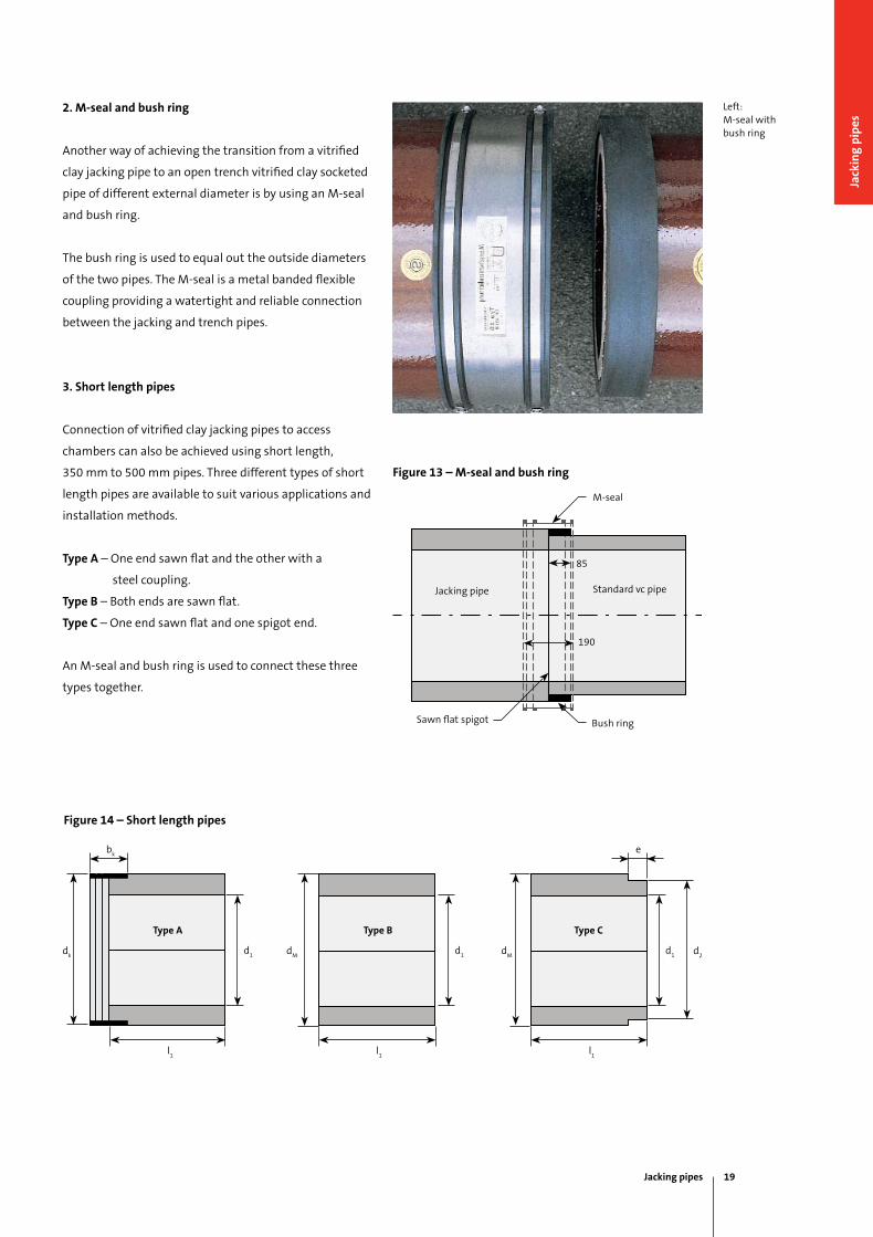
2. M-seal and bush ring
Another way of achieving the transition from a vitrified
clay jacking pipe to an open trench vitrified clay socketed
pipe of different external diameter is by using an m-seal
and bush ring.
The bush ring is used to equal out the outside diameters
of the two pipes. The m-seal is a metal banded flexible
coupling providing a watertight and reliable connection
between the jacking and trench pipes.
3. Short length pipes
Connection of vitrified clay jacking pipes to access
chambers can also be achieved using short length,
350 mm to 500 mm pipes. Three different types of short
length pipes are available to suit various applications and
installation methods.
Type A – One end sawn flat and the other with a
steel coupling.
Type B – Both ends are sawn flat.
Type C – One end sawn flat and one spigot end.
An m-seal and bush ring is used to connect these three
types together.
85
Connections to standard pipes and shafts
Rocker pipe for connection of jacking pipesto standard pipes with two different outsidediametersFor the connection to chambers or v.c. pipesnormal or high strengthVitrified clay adaptors are used for the transi-tion to standard and high load series socketedpipes. The adaptors consist of 1.0 m longjacking pipes with a coupling on one end andthe other end milled to the external diameter ofthe pipe to which the adaptor should be con-nected. With the aid of a P-ring, the transitionto "K" or "S" jointed pipes (in accordance withjointing system C) can be created.A further way of achieving the transition from avitrified clay jacking pipe to a vitrified clay sock-eted pipe is provided by the use of an bush ringto equal out the different diameters. Then, with
the aid of the metal banded flexible coupling (M-seal type 2B), a watertight and reliable connec-tion is created. The external diameters of thecomponents to be connected must be deter-mined precisely prior to ordering the bushes.
Bush types according to outside diameter dif-ferences. To combine with M seals.
Pipe DiameterNominalAveragelengthweight
DNd1d3d3dMl1+0/–1+0/–1max.+/–1kg/pc
(N)(H)
250+/–3299318360 +0/-61000105
300+/–5355376406 +0/-101000125
400+/–6486492556 +0/-121000240
500+/–7,5581609661 +0/-151000295
600+/–9687721766 +0/-181000350
Dimensions in mm; technical changes reserved
Coupling type 1 or 2
In the standard and high load series,transitionsto socketed pipes with "K" and "S" joints inaccordance with system C can be achieved withthe aid of the adaptor ring (P-ring).
DN 250 - DN 600 adaptorOptionally with coupling type 1 or to.
Optionally with d3 dimension for standard or high load pipes.
M-seal (type 2B)
Jacking pipe DN 500 covered steel coupling or V4A
Standard v.c.pipe
Cut off milled spigotBush of rubber elastomer; b = 80 mm(thickness must be matched to the dif-ference to be bridged)
21
Outsite diameter(mm)
thickness(mm)4812162432
160 to 199xxxxx200 to 299xxxxxx300 to 1399xxxxx
DN(mm)
External diameter
dM
Metal banded flexible coupling type 2Bv.c. normal strength
class (N)v.c. high strength
class (H)
150213190-215 or 200-225
200276225-250 with
bush 16 mm thick265-290
300406335-360 with
bush 24 mm thick385-410
400556460-490 with
bush 32 mm thick495-525 or 510-540 or
520-550
500661570-600 with bush
40 mm thick (16 and 24)610-640 or 630-660 or
650-680
600766685-715730-760 or 750-780
700870800-830 or 820-850860-690
800970900-930 or 920-950970-999
Width metal banded flexible coupling type 2B DN 150 and DN 200: 150 mmWidth metal banded flexible coupling type 2B = DN 250: 190 mm
Figure 13 – M-seal and bush ring
Figure 14 – Short length pipes
Left: m-seal with bush ring
Jacking pipe
Bush ring
Standard vc pipe
85
m-seal
190
Sawn flat spigot
dk
d1
bk
l1
dm
d1
l1
dm
d1 d
2
l1
e
Type A Type B Type C
Jacking pipes 19
Jack
ing
pip
es
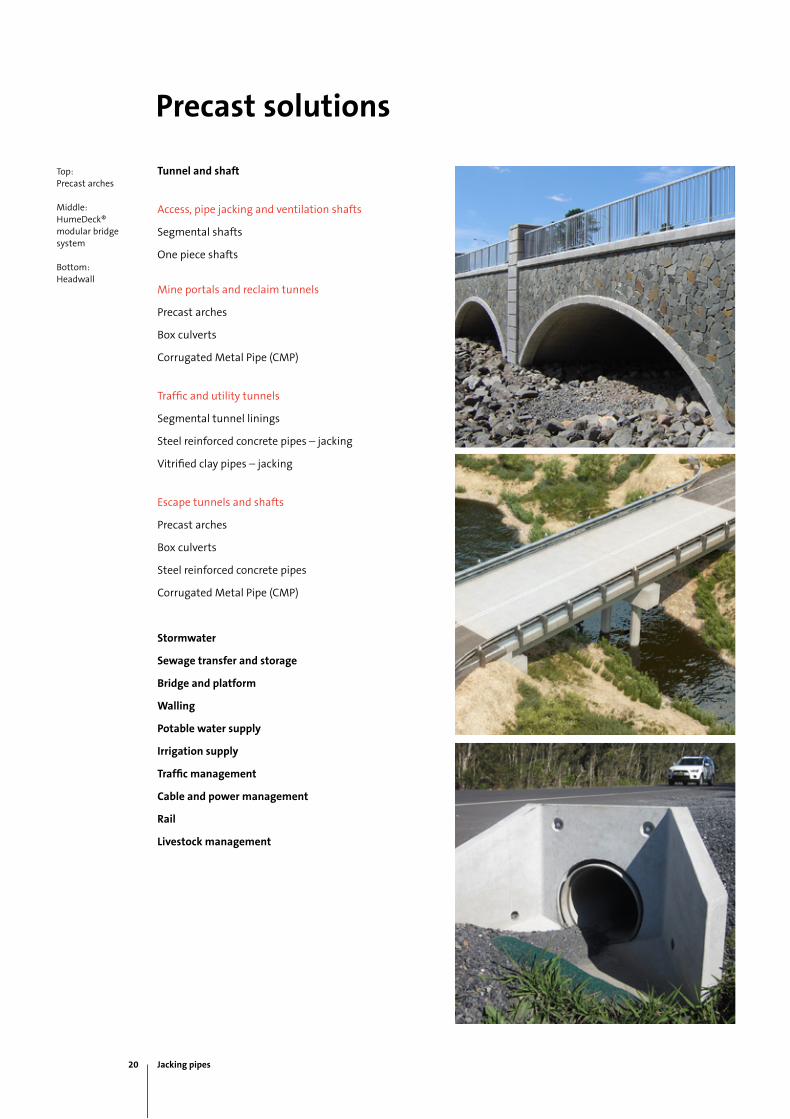
Precast solutions
Tunnel and shaft
Access, pipe jacking and ventilation shafts
Segmental shafts
One piece shafts
mine portals and reclaim tunnels
Precast arches
Box culverts
Corrugated metal Pipe (CmP)
Traffic and utility tunnels
Segmental tunnel linings
Steel reinforced concrete pipes – jacking
Vitrified clay pipes – jacking
Escape tunnels and shafts
Precast arches
Box culverts
Steel reinforced concrete pipes
Corrugated metal Pipe (CmP)
Stormwater
Sewage transfer and storage
Bridge and platform
Walling
Potable water supply
Irrigation supply
Traffic management
Cable and power management
Rail
Livestock management
Top:Precast arches
middle:HumeDeck® modular bridge system
Bottom:Headwall
20 Jacking pipes
National sales 1300 361 601
humes.com.au
Contact information
Melbourne
Ph: (03) 9360 3888
Fax: (03) 9360 3887
Tasmania
Launceston
Ph: (03) 6335 6300
Fax: (03) 6335 6330
South Australia
Adelaide
Ph: (08) 8168 4544
Fax: (08) 8168 4549
Western Australia
Gnangara
Ph: (08) 9302 8000
Fax: (08) 9309 1625
Perth
Ph: (08) 9351 6999
Fax: (08) 9351 6977
Northern Territory
Darwin
Ph: (08) 8984 1600
Fax: (08) 8984 1614
Head Office
18 Little Cribb St
milton QLD 4064
Ph: (07) 3364 2800
Fax: (07) 3364 2963
Queensland
Brisbane/Gold Coast
Ph: (07) 3866 7100
Fax: (07) 3866 7101
Bundaberg
Ph: (07) 4152 2644
Fax: (07) 4152 5847
Rockhampton
Ph: (07) 4924 7900
Fax: (07) 4924 7901
Sunshine Coast
Ph: (07) 5472 9700
Fax: (07) 5472 9711
Toowoomba
Ph: (07) 4694 1420
Fax: (07) 4634 3874
Townsville
Ph: (07) 4758 6000
Fax: (07) 4758 6001
New South Wales
Canberra
Ph: (02) 6285 5309
Fax: (02) 6285 5334
Grafton
Ph: (02) 6644 7666
Fax: (02) 6644 7313
Kempsey
Ph: (02) 6562 6755
Fax: (02) 6562 4235
Lismore
Ph: (02) 6621 3684
Fax: (02) 6622 1342
Newcastle
Ph: (02) 4032 6800
Fax: (02) 4032 6822
Sydney
Ph: (02) 9832 5555
Fax: (02) 9625 5200
Tamworth
Ph: (02) 6763 7300
Fax: (02) 6763 7301
Victoria
Echuca
Ph: (03) 5480 2371
Fax: (03) 5482 3090
This brochure supersedes all previous literature on this subject. As the specifications and details contained in this publication may change please check with Humes Customer Service for confirmation of current issue. This document is provided for information only. users are advised to make their own determination as to the suitability of this information for their own specific circumstances. We accept no responsibility for any loss or damage resulting from any person acting on this information. Humes is a registered business name and a registered trademark of Holcim (Australia) Pty Ltd. Plastiline is a registered trademark of Holcim (Australia) Pty Ltd. STEiNZEug KERAmO is a registered trademark of STEiNZEug Abwassersysteme gmbH. Swiftlift is a registered trademark of iTW Construction Products Australia Pty Ltd. © June 2012 Holcim (Australia) Pty Ltd ABN 87 099 732 297
National sales 1300 361 601
humes.com.au
A Division of Holcim Australia
Recommended