f
/ 4GS COMPUTERS, INC.
ivlanual of Data Processing Standards
1 ' G S COMPUTERS, INC.
TABLE OF CONTENTS
%vision Page
Chapter 1. General Information Data Processing Standards Scope o f Manual Manual: Care, Use, and Revision Equipment Specifications Software Programs
Chapter 2. Problem Analysis and P m g ~ a m Developnent Problem Definition Progran l k f i n i t im Pro~-pzi~n I dent i f i ca t ion Input-Output kyout
Card Layout P r in t e r Layout
Program Development Loge Design Coding Tes t Preparation Program Testing Docmentation
Chapter 3 . Programming Standards Logic Design-Flcw Charts
Flow Chart Symbols F h Chart Cmventions
Program Organization Coding Sheet Sequence Mmry Layout
Coding Qlaracter Writir.g Standards Labels
Standard Label Chart Standard Halts S t a ~ d a r d Nessages C m e n t Cards
Program Tes t i n g Test Plan Form C m n Coding E r r o r s Testing Procedure COBOL Pro;grarro;ling Standards
Chapter 4. bcunentat ion Cantents o f Program Manual Dispcxition o f Documentation and Progran Cards Program Abstract Sub-Routine Cocumentation
4GS COMPUTERS, INC.
Chapter 5. Opemting Standards Propam Library Pmgram Change Record
mapter 6 . Appendix Key Punch Program Card-general COBOL DmPn Card ALP Drum Card FORTRAN bun Card Fonns to be Used
A G S COMPUTERS, INC. i
General Information
%vision Page
i 4 G S COMPUTERS, INC.
Chapter 1
General In fomt ion
' G S COMPUTERS, INC.
Chapter 1 Page 1
General Information
Data Processing Standards
Standards are rules s e t IQ and established by authority to provide rreaningful information i n a consistent, usable form. When complex and detailed problem are analyzed a d solved in a similar manner, standards are necessary for the useful exchange of infomation. Standards are used t o give us a guide f o r gathering pertinent information which is needed. From the i n i t i a l statement t o production operation, standards establ ish the procedures t o investigate, develop, and solve a problem. Standards are called f o r w h e n problem solving techniques o r groups of problem are related by a mman need. To those who must analyze and solve problems o r operate c ~ n p l e x machines, star~darc3s are the source f o r information m d ins t ruc t im t o carry out this w o r k .
In data processing and the use of computers, standards are necessary f o r the successful computer shop. Because of the many detailed s teps t o be taken before a problem is ready f o r production operation the need f o r gathering and recording pertinent information accurately and in suf f i c i en t de ta i l , b e a m s important. A programer in making an analysis gets in to rmnifications of a problem which, i n the days before computers, were the proper business o f several people. No one considered it necessary f o r a single person t o beame acquainted with all the ins and outs of a job be- cause the manual o r rre&anical operations formed t h e i r own division of re- sponsibili ty. ?he computer unifies a l l these aspects, thus the need t o know al l the de ta i l s which must be recorded in a useful manner.
In set tin^ Data Pmcessinp, Standards a method of operation is develoned .- w h i c h s e t s guide l ines f o r obt?,jkcinp. thennecessary information. This method. is the sequence of s teps foiicx;je; I- gatherim information and the techniques developed f o r using a c q u t e r t b jolve a Standards relieve the prograrraner of the m y l i t t l e bookkeeping decisions by establishing a uniform way of assiming program labels and organizing the program.
This manual o f Data Processing Standards, the fonda t ion f o r exchange of information among all people i n data processing, provides:
(1) a cornman frame of reference, ( 2 effect ive c~inmunication among people, ( 3) effect ive cmunica t ion be-be en people and machine, (4) c lea r cu t definitions of terms, ( 5 ) personnel responsibi l i t ies , and (6) procedures of operation.
The manual is the programnerls working tool* Tne pmgramner is asked to l e a m and understand the use of these standards, ?he sucoessful pmgmnmr masters these precepts.
'fGS COMPUTERS, INC. Chapter 2 Page 2
Scope of t h i s Manual of Data Processina Standards
The manual, designed to explain the de ta i l s o f p n o g r d g and operating standards is divided i n t o f ive major sec t ims.
Program Analysis and Problem &fini t ion
This section is an outline of steps taken t o solve a problem offering a description of developrent fm the or ig ina l problem defini t ion t o p m grammer, and a tabulation of information t o be recorded,
Prograunhg Standards
?he standards and mnventions o f p r o , m i n g a re defined here. 'he m c s t important reference is t o f l c w charts and labels. Each programing task is explained and related to logical program development.
Cocumen tat ion Standards
Cocumentation is the orderly collection and arrangement of information about a program. ?he P r o g m Manual gives the interested person information about every aspect of the ploblem and ref lec ts the care, understanding and ab i l i ty o f the p r o g r m r .
Operation Standards
Standard practice f o r machine use and tf.le function of the propam library are described.
Appendix
The appendix contains programing te&niques , and glossaries o f cmputer terms, Financial Pub l i sh i~ r ; % - y y terms and standard abbreviations f o r docmentation,
M- - - . , , , A , - : ;, C a r e -- -L dse
Additions and revisions t o t h i s manual w i l l be made only with approval of the head of 'che technical s t a f f , Suggestims may be directed to h i s at tent ion f o r review. Each pmgMmner w i l l be responsible for keeping this copy c u m t as additions are ma&.
You are expected t o understand and apply the standards established i n t h i s manual. Your success as a programer is measured by the success of your p r o g m , by the understanding, exposition and organization o f the in- formation in your program m u a l , and by the simplicity and c la r i ty of your operating ins tructions .
AGS COMPUTERS, INC.
Chapter 1 Page 3
General Information Equipment Specifications
Quipnent specifications m u s t be obtained f m n the c l ient by tfle lead prognmner on the project. ?he information must answer questions i n the follming categories :
CPU Configuration :
mdel , storage, storage protect Instruction s e t Nuher and type of channels
I I O Devices ( f o r each device the follcwing ie necessary) :
Device type Device Address ( es Control unit 5 p e and address System Standard symbolic address Specid features (by device): Printer: Speed, # characters
Universal ha rac t e r s e t Tapes : 7 and/or 9 track
Conversion f estures Simultaneous WW TAU
Disk units: F i l e Scan

AGS COMPUTERS, INC.
Chapter 11
Problem and Pmgwn Development
T G S COMPUTERS, INC.
Chapter ll Page 1
Problan and Program D e v e l o p n t
A prcblem evolves into a program through a series of 6 steps:
(1) Problem Cefinition ( 2 Numerical h a l y sis ( 3 Program Definition ( 4) Program Identification ( 5 ) Input and Output B s i ~ (6) Program C c v e l o p n t
The f i r s t f ive s a p s ansist of gathering necessary fac t s and display- ing them i n reasonable order f o r use i n s t ep siw,.progranming. 'he logica l order of these steps should be fo l lmed in gatherzng f a c t s , developing in approach, and cataloguing the necessary informtion in a manner and form which permits both a check l ist and quick reference f o r needed information,
Problem Definition
A written deswiption of the problem defines the major considemtions and the special characteristics affect ing the problem solving approaching, Information included in is s tep w i l l include:
(1) Purpase ( 2 ) Input
Source, form, sample ( 3 ) Output
Fom, sample ( 4) Special Characteristics (5) Pmblem Glossary
Defines terms unique i n meaning t~ -this problem
This general statement of the prablm describes elements to be developed i n d e t a i l by the program definition,
N m r i c a l Analysis
Tne nunerical analysis of ari-thnetic operations show the factors , where they came from (input from card o r computed by program), the arilhnetic operat ims, and the intermediate and f i n a l resul ts . When a formula is used it should be s ta ted i n -the m o s t general f om, in the spec i f i c fonn to be used, and the transformation f r m one t o the o-ther. Equations using a representative example of the calculations show the actual arit-hmetic operat ims, Indicate fhe m g e s and l imits of the f a c b r s imposed f i r s t by the problem and secmd by the capacity allowed f o r i n the progmm. Show where adjusmnt in the
AGS COMPUTERS, INC.
Chapter ll Page 2
answer are made ; f o r example, the rounding 5 t o adjust half cents o r greater up t o the next cent. This is a f a c t gathering section; the sequence and manner to be used by the program is determined i n the P m g m Cefinition.
Program Cefinition
'Ihe developnent of prog.m specifications from the problem defini t ion produces a program definition. Several p r o g r w developed from a single problem definition form a progmm system. The program defini t ion is e x p l i c i t in the de ta i l information required, the mathmatical. techniques, the control, the inputs and outputs and its relationship to o the r similar programs. Step three w i l l mver the fo l la r ing information:
(1) Purpose (2) Input
describe. f ie lds on card layout forms ; type; source; composition; l i m i t s ; volume
(3) Output describe f i e l d on card layout and p r i n t layout f o m ; type , source ; compcsi t ion ; l i m i t s ; volun?e
(4) Factors examples of the calculations ; specif ical ly the sequenoe and manner the progran w i l l use i n calculations
( 5) Sped a1 considerations res t r ic t ions ; exep t ions ; e f fec t on current practice; relationship t o other pmgrans
(6) Pmgran glossary defines terms unique i n meaning to this Pmg-
P r o g m Identification
Identification n u h e r s w i l l be assigned t o a l l program. The assign- ment will be made when the exact definition has been established. The identification is a feu-character alphanumeric f i e l d in the following format:
A B C D Specific Module
Major mmponent of a systen
Sys tern and/or application
Major Application and/or c l i e n t
?he ident if icat ion nwber is pmched intn card column 73-76 m d appears
AGS COMPUTERS, INC. Chapter LL page 3
on the assembly l i s t i ng . If the source cards f o r one propam are used i n t h e developnent of a second program care should be exercised to g e t the o ld pmgran number o u t and the new one in .
'Ihe f o u ~ c h a r a c t e r mdu le I D is punched i n t o the ob jec t t e x t cards through use of the TITLE card. The module I D is a l so the nane by which the program is h a w n to the linkage e d i t o r throu* use of CSECT and START cards. Entry points -to a module w i l l be iden t i f i ed by a fif.th haracter.
Input- Output Layout
Layouts w i l l be prepared f o r the formats o f a l l inputs used and outputs produced by the program. 'Ihis s h a l l be done, without exception, before pro- gramming. The d e t a i l of these layouts may be changed during the design of program logic and reanalysis o f program specif icat ions, Neat, accurate docments r e f l ec t ing the current format o f inputs and outputs must be avail- able; i f a change is made they provide the p i n t of departure, Tnese layouts w i l l be i n a r p o m t e d i n the progran docunentation.
CARD Layout
On ?5e 1IY.I C a r d Layout form used to i l l u s t r a t e all card input and output f i e l d s , describe f i e lds by name, f i e l d limits by v e r t i c a l l i nes . In fne '
space on the form give the following information, i n as much detail as n e c e s s q :
Field Data C m is tency Column Size Name Description Source Type Limits
Alwa l imi t s o f f i e l d
Nuneric lirriits o f codes
limits of -ge
Describe b r i e f l y the card preparation procedures for each kind o f card,
AG S COMPUTERS, INC. I
Chapter 11 Page 4
Printer Layout
On the Program Planning and Testing Fornat f o r High Speed Pr in ter , i l l u s t r a t e a l l printed output, ident ify by the report name and the program number t h a t produces it. Show t h e f o l l w i n g on yaur p r in te r output layout:
Write in preprinted headings , underline Write i n einitted headings Write two sample l ines f o r each type of d e t a i l pr int ing Show punctuation f o r every edited f i e l d Indicate maximum value i n eaah f i e l d Show all total levels Shm en t i r e ver t ica l and horizontal dimension of form Ehit headings and ident if icat ion f o r output on blank paper
Program Ccvelopnent
Tne steps of problem analysis &scribed in the preceding pages provide the necessary information f o r developing a progrm. Propanning is ccmposed of -the f ive tasks : logic design, coding, t e s t preparation, p r o g m tes t ing , &cumentation, considered and executed sequentially. 'he importance, de ta i l and complexity of these tasks require standards defined in mapte r 3 , Pro- gramming Standards.
Logic Design
Three stages of propam logic m u s t be completely designed and documented before any subsequent p m g ~ m n i n g tasks an? begun.
1, Analy3 2 .; ~ J I C !. .-: , , 1 ~ , organization-analys is of -the progran definition t o es tablis$ s.,-e:l;L,~ 21. .qz f o r designing -the canputer oriented logic.
2. Design of the general fLow o f program logioMACR0 flow &art- the major logical elements, i l lus t ra ted in a flow chart, required t o meet program specifications .
3, Design of the speci f ic logical processes-MICW3 flow chart-the individual logical s teps, i l lus t ra ted in a flw chart , within each major logical element. Micro flw charts show the connecting linkage.
A th i rd level of flow charts, called the ABSOLUTE flow chart, represents each instructim by a separate symbol t o explain and i l l u s t r a t e a complicated b g i c a l s t r u c t u ~ .
A summary of the -three f l a w & a r t levels makes the following distinctions :
Macro F lm Chart - one symbol f o r each major logica l function; one symbol per routine,
Micro Flcrw Chart - one symbol f o r a series of instructim within a routine; me symbol for several instructions .
Absolute Flow Chart - one symbol f o r each instruction,

AGS COMPUTERS, INC. Chapter 11 Page 5
Coding
Coding is the statement, in machine-acceptable language, of the logic described in the flow chart. Coding must be wri t ten legibly and accurately to minimize key pun& errors. You w i l l follow t h i s sequence in which basic program components w i l l be organized t o permit the standardizat im of program cmtinuity :
P r o g m Description Standard Halts and Non-Standard H a l t s busekeeping Routines Input- Output Routines Main b g i c work Areas Special Subroutines
Test Preparation
Test data, used t o verify the accuracy and r e l i a b i l i t y of a program in meeting the requirements of program defini t ion, shall be developed during the f i r s t two p r o g r d n g tasks. As decisiors , logic tests and control functions are considered, test data s h a l l be prepared t o verify log ic and coding. Test data should be reviewed by someone famil iar w i t h the problem defini t ion to insure t h a t no obvious a n d i t i o n has been overlooked, Test cases s h a l l be used for desk checking the program logic. %e flow of l o g i c w i l l be checked by processing simple t e s t data i n the dry run mode. K e y punch, coding and logic e m r s can be detected in this way. You are responsible for preparing the test data and organizing the test plan.
Program Testing , "
6 ?-- --A
+ , - b A ~ i , at> hast aaia n;2 ~3;erating instructions is submitted t o the operatidns sec;tbn foe f e s t ( o r assemble o r l ist as the case may be). Sufficient past t e s t information should be cal led f o r to provide a clue tn your trouble i f the test fai led. This includes memory dwrp, reg i s t e r ad- dresses, and the output. You should, a f t e r each test, remrd the results =nd measure your progress with regard t o the overal l t e s t plan. When all requirements are met, the t e s t data and test output are retained in the pm- gram documentation. To be sure you have understood and sa t i s f i ed a l l the program specifications, review the test resul t s with the p r o p a director,
It is the responsibility of the lead p r o g r m r to establ ish regular access to the amputer f ac i l i ty .
; AGS COMPUTERS, INC.
chapter 11 Page 6
Descriptive material is compiled throughout problem analysis and program developnents. Tne f i n a l task is t o review, organize and e d i t f o r accuracy and l eg ib i l i t y a l l this information included in the permanent progrwn reoord. Important points of log ic should be clear ly defined; the purpose and capabi l i t ies of the program &scribed in non-technical language. A 1 this doamentation is collected i n a Pro- Manual, and includes:
Problem Definition Program Definition Flaw Charts Input, Output Layoul Formulas and Equations Assembled Listings Test Data and Test Results Operating Ins tmctxhn Program Abstract
G S COMPUTERS, INC.
Chapter ll1
Programing Standards
A G S COMPUTERS, INC.
Chapter 111 Page 1
Prograrroning Standards
Programming standards , established in the amrncn progran areas of flow charts, organization, mding, test ing, provide consistent, r e l i ab le pro- graming techniques. These standards are the s t a r t i n g point f o r a g a d pro- gram.
Fla* chart t e d n o l c p y and practice, adapted f o r computer use, a q u i n s new meaning and application. Our symbol definitions when used intel legently gives the necessary i n f o m t i o n demanded of a flcw chart.
lhemmic o r uniquely systanatized l&beh are not b u i l t on the general, underlying principles required t o amomnodate a large n&er of varying labels. Standard labels eliminate the need f o r each p r o p m r t o build h i s own system. Private label systems are incomplete, quickly b e m meaningless, change be- tween programs, and defy the exchange of information, Private labels w i l l no t be used.
Logic Design-Flw &arts
A flow chart, the p i c t u x representation of a problem t o be put on a mmputer, and the basic flow of information shows the sequence of operations performed by a cmputer in the execution of a problem. An operation a u a l l y mnsis ts of a nLonber of program steps .
A f l c w chart must have a set of syn-bols to show the following:
(1) The kind of operations t o be p e r f o m d . (2) manges i n the seqEnce of opemtion as the result
of a t e s t , ( 3 ) Qlanges i n the sentrncc -. .-,lG.G.L,.. ; the wsult
of rrsdifying an ins t ruce- : : (4) Explana-toxy information and i n i t i a l and i t ions . (5) b e c t i o n links t o a pa r t of the problem which
is mntinued on another page,
?ko kinds of flow charts are referred to in t h i s manual. The macro flow chart shcws: the major operation synlbols i n t h e i r log ica l context within the general ans t ruc t ion of Lle pmblem; the major decision pints, inputs and outputs, major s t a r t s and ha l t s ; the o v e r a l l m i c i s r a t i o n s of the problem and how they t ie in and re la te t o each other. ?his is -the initial statement of what the problem is and haw t o solve it.
AGS COMPUTERS, INC. Chapter 1ll
Page 2
B e micro f l o w chart develops in deta i l the contents of each major operation symbol. A m j o r operation involves the logica l operations of arithmetic s toring, canparing, branching. 'he micro flow chart shows w i t h symbols and explanation the precise logic t o solve the problem. Each symbol and its contents must give the necessaq information so t h a t the program may be written direct ly from the micro flow chart. A well prepared micro w i l l be so clearly dram t h a t a programer m y wri te the program without hesita- t ion. B e work of a progrm is i n the f l m charts ; the coding is a matter of writing only.
A third level , referred t o as an absolute flow chart, shows each pro- gram s tep in a symbol. To explain a complex decision operaticn t h i s degree of de ta i l may be necessary.
A f l w chart ident if icat ion systen assigns an a l p h a n m r i c a d e to each symbol. ?his code becomes p a r t of the branch l a b e l to insure a d i rec t COP relat ian between mding labels and f h chart symbols, ?he m i m flow charts are developed at a l e v e l allowing the programer t o code d i rec t ly from it even though each symbol represents more than one instmcticn,
Flm Chart Symbols
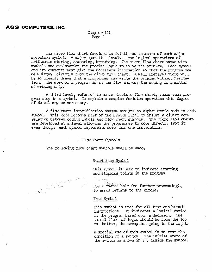
The following f l w &art symbols s h a l l be used.
S t a r t Stop Syrfhl
This symbol is used to indicate s t a r t i n g and stopping points in the pmgr\am
Tdi '*nardH h a l t (no fur ther processing) , i t o amrw returns t o the cimle.
Test Symbol .. This symbol is used f o r all t e s t and branch instructions. It indicates a logica l choice in the program based upon a decision. Tie normal flow of logic should be from the top t o bottom, the exception going to -the r ight .
A special use o f t h i s symbol is to test t h e condition of a switch. The i n i t i a l s t a t e of the switch is shown in ( ) ins ide the symbol.
AGS COMPUTERS, INC.
Chapter I l l Page 3
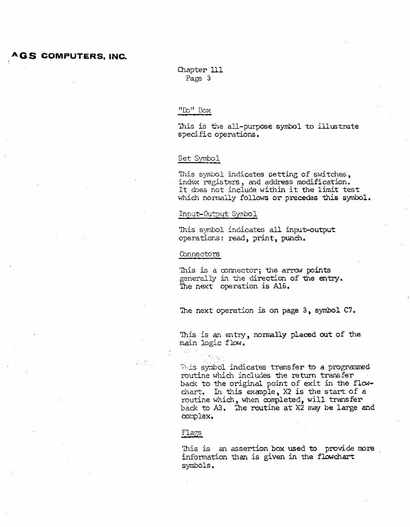
"CO" Box
Tnis is -the all-purpose symbol t o i l l u s t r a t e spec i f i c operations.
Set Synbol
This symbol indicates se t t ing of switches, index regis ters , and address modification. It cbes not include within it the l imi t t e s t which n o m l l y follows o r preceder; this symbol.
Input-Output Symbo 1
Tnis symbol indicates a l l input-output operations : read, p r in t , punch.
Connectors
?his is a connector; the a m points generally in the direction of -the entry. Tie next operation is A16.
?he next operation is on page 3 , symbol C7.
Tnis is an entry, norrnally placed out of the main logic flow.
3 .
'in is symbol indicates t r ans fe r to a p r o m m d routine which includes the retum transfer badc t o tAe or ig ina l point o f e x i t in the flow- chart. In t h i s exanple, X2 is the start of a routine which, when completed, w i l l t ransfer back t o A3. 'he routine a t X2 may be large and complex.
Flags
This is an assertion box used t o provide mre information than is given in the flowchart s ~ o l s .
A C S COMPUTERS, INC. Chapter 111 !
Page 4
Symbols help t o graphically i l l u s t r a t e a problem and haw it is solved. Decision points and input-output operations are eas i ly found, s ince these are the most l ikely places f o r changes. The symbols are no t suff ic ient i n themselves, hwever, and pertinent &cumentation in the symbols, and f lags, must be used.
Flaw Chart Conventions
(1) Tne Standard Symbols s h a l l be used to describe logical functions.
( 2 ) Tne Standard f inancial and data processing notations and authorized .abbreviations sham i n the Appendix sha l l be used. A legend page must define all exceptions to a e s e standardr;.
( 3 ) A macro f lm chart sha l l be dram f o r every program. It s h a l l identify and i l l u s t r a t e every logical operation with a separate symbol. Each propam sha l l be divided into a t l e a s t f ive and no mre than 17 logica l operations ; the macro f lm chart s h a l l be diagramed on one sheet of 8 1 / 2 x 11 inch white bond paper.
(4) An alphabetic P r Z code s h a l l be assigned i n sequence t o each symbol on the macro f l o w chart. Tne following l e t t e r s w i l l not be used: I , 0, Q, U , and V. These are e i t h e r reserved f o r special purposes i n -the Standard Label System o r are r e s t r i c t ed because of the tendency to cmfuse them with o ther handwitten alphabetic o r numeric characters.
(5) A micro flow chart whall be dram f o r every s igni f icant operation shown on the general flow chart. It s h a l l i l l u s t r a t e the logical process t h a t occurs within each major operation. 'Ihis level o f flow chart s h a l l specify the l i n k e e between operat ims. Each micro chart rnqyi- c - i * ji- ;.? to a m ~ i m l m 03 99 symbolic figures and s h a l l be on r,,, side cf i)d,>r/2 x ,-'-:la hn-2 -----A
' : r . Z
.. . .
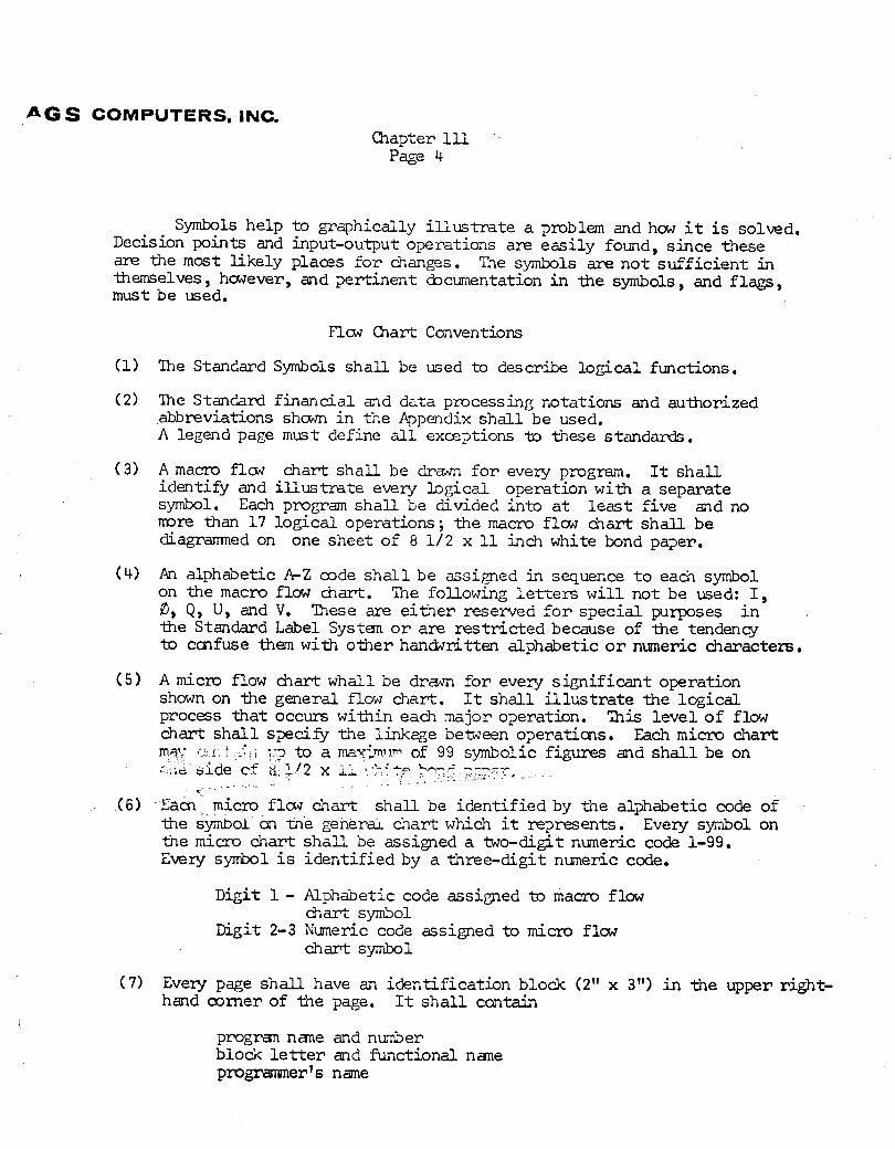
(6) Sacn micro f l a w chart s h a l l be identif ied by the alphabetic code of the symbol on me genera chart which it represents. Every symbol on the micro chart s h a l l be assigned a two-digit nuneric code 1-99. Every symbol i s identif ied by a three-digit n m e r i c code.
Digit 1 - Alphabetic code assimed to macro flow chart symbol
Digit 2-3 Numeric code assigned to micro f l w chart symbol
(7) Every page sha l l have an identif icat ion block (2" x 3") i n the upper right- hand comer of the page. It s h a l l contain
progran nane and number block l e t t e r and functional nane programer's name
1 4 G S COWIPUTERS, INC.
Chapter 111 Page 5
( 8) Both levels of f l o w charts must accurately and consistently repre- sent the program logic. Tney must be updated with all changes made.
(9) All connectors and entry points must be shown and identif ied. All input and output operations sha l l be sham as distinct:symbals on the macro flow chart a ~ d shown i n micro f lw chart form when other than a s ingle instruction is required.
(10) Each symbol s h a l l contain a br ief description of the log ic it represents. Standard notations and abbreviations s h a l l be used. (see Rule 2 )
(11) A c h s e d subroutine s h a l l be i l lus t ra ted as a separate operation.
(12) Fla* charts s h a l l read from top to bottom.
Program Organization
General groups of operations such as housekeeping, input, output, main logic, work areas, acolmulatols , counters, and constants which occur in every program, s h a l l be found i n the same place i n program coding sheets.
'he SF'S card allows b.ro d ig i t s f o r page nunbering: The following page numbers are assigned t o spec i f i c operations.
Coding Sheet Sequence
Page 00 C m e n t s : Program t i t l e and identif icat ion Propaminer name Asseqbly date and number of
assembly : C n n ~ ? i ~ : k_t up cmdi t iom
Components used, .punch , reader, p r in te r Radial stackers ~f other than normal Punch and norrral read Special 140 3 instruct ion
carriage control tape alpha numeric p r i n t chain 6 o r 8 inch ve r t i ca l spacing
Nessages identif ied by label , and cause
Comments cards desmibing the program a t sane length
Input cards identif ied by type, nane, code
( 2 ) Pages 01-10 Housekeeping Normalizing of counters, switches,
annectors , accunulators Print registrat ion mut ine
A G S COMPUTERS, INC.
&ap t e r I l l Page 6
( 3 ) Pages 11 - 20 Input ; cards read, tested f o r sequence o r mde and -the input stored in work areas
(4) P e e s 21-30 Output ; transferred f m n cc3npute work areas -to p r i n t areas, edited and printed
(5) Pages 31-70 M a i n Logic
( 6) Pages 71- 79 klork areas . A separate page f o r each category of work area should be used.
( 7) Page 80 ACCW%JLA?OEES and COUNTEFS are work areas s e t aside in which t o cb arithmetic operations.
(8) Pages 81-89 CONSTNJTS such as numbem, edit words and alphabetics t o be printed in the heading .
Pages 90-99 MESSSE Work areas
Coding
Ccding involves writing instructions fmm flaw charts; a s s i m g labels to branch points , areas, cans tants , h a l t s ; and writing c m n t s , punched in cards along with the instructions, to describe constants, s teps and opera- t ions in the p r o g m .
Character Writing Standards
Numbers and d a r a c t e r s may be misread by key punch operators when penciled coding sheets are being keypunched unless care i s used i n writing. The following s t y l e of writing numbers, alphabetics and special characters w i l l be used.
I AGS COMPUTERS, INC.
Chapter I l l Page 7
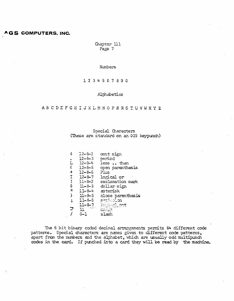
Numbers
Alphabetics
Special Characters (Tnese are c tar~clard on an 029 keypunch)
cent s ign period less . . -than open parenthesis Plus logical o r exclamation mark &Uar sign as ter i sk c l a e parenthesis S T - . - - 7 ..-m
Tne 6 b i t binary coded decimal arrangements permits 64 d i f ferent code patterns. Special characters are nmes given t o different code patterns, apart f m the numbers and the alphabet, which are usually odd multipunch co&s in the card. If punched into a card they w i l l be mad by the ma&-he.
i ' G S COMPUTERS, INC. Chapter 111
Page 8
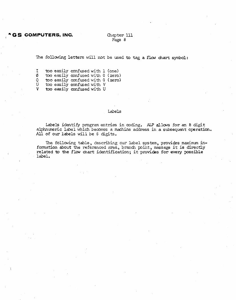
?he follcwing l e t t e r s w i l l not be used to tag a flw &art symbol:
I too easily confused with 1 (one) 8 too eas i ly confused w i t h 0 ( zero) Q too easi ly m f u s e d with 0 (zero) U too eas i ly confused with V V too eas i ly confused with U
Labels
Labels identify program ent r ies i n coding. ALP allcws f o r an 8 d i g i t a l p h n m r i c label which b e a m s a machine address i n a subsequent operation. A l l of our labels w i l l be 6 digits.
Tie follcwing table , describing our label system, provides m a x i m u n in- formation about the referenced area, branch pint, message it is directly related to the flaw chart ident if icat ion; it provicks f o r every possible label.
i G S COMPUTERS, INC. Qlapter ll1 Page 9
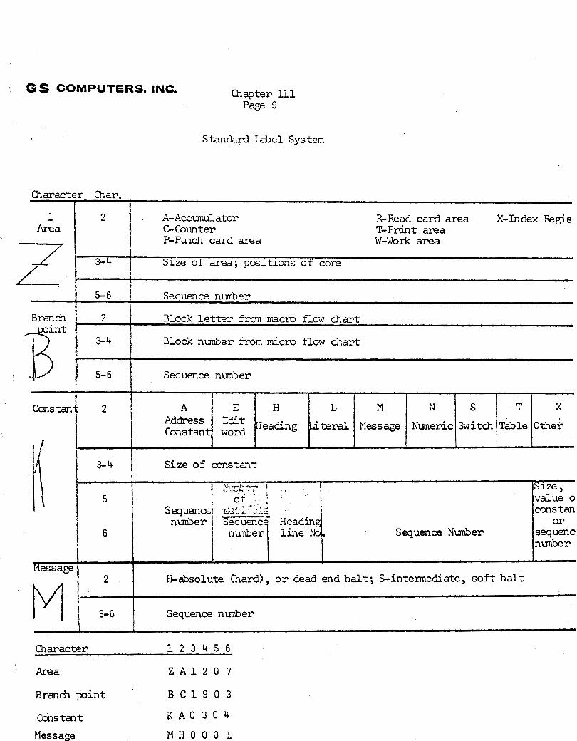
Standard Label System
Character Char, I
%Read card area X-Index Regis T-Print area W-Work area
1 Area
7
2 . A-Accumulator GCounter P-Punch card area
1 3-4 1 S i z e o f c o n s t a n t
I
3- 4 Size o f area; posit ions o f core
h
5- 6 Sequence number
Branch 2 Block l e t t e r frcm macro f l o w &art !
3-4 1 Block nmber f r o m micro flow chart
/ 5- 6 Sequence nwber
Cons tan L
teral
H-absolute (hard), o r dead end ha l t ; S-intermediate, s o f t h a l t
Sequence nmber \
1
Character 1 2 3 4 5 6
' ~ r e a Z A 1 2 0 7
Branch pint B C 1 9 0 3
Cons tan t K A O 3 0 4
Message M H O O O 1
M
Message
s=ze 
value o cons tan
o r sequenc nunber
I )h-7"$"? ' I
5 I of i ' I
N
Nmeric
FIessage k I
Sequence NuDnber
Sequena,: &fi"L;
S
Switch
1
n u b e r 6
T
Table
Sequence Heading
X
Othe*
n w b e r l i n e No.
AGS COMPUTERS, INC. Chapter 111
Page 10
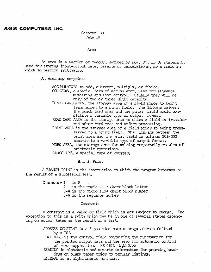
Area
An h is a section o f rrerr,o~/, defined by DW, DC, o r D6 statement, used f o r s tor ing input-output data, results of calculations, o r a f i e l d i n which to perform ari-thmetic.
An Area may cmpr ise :
ACCUMUL.4TOK to add, subtract , multiply, o r divide. CWNTEFS , a special form of accumulator, used f o r seauence
numbering and loop control. usually they G i l l be only of two o r three d i g i t capacity,
PUNCH CARD APSA, the storage area of a f i?ld p r i o r to being transferred t o a punch f ie ld . ?he l i n k q e between the pimch card area and the punch f i e l d would con- s t i t u t e a variable *ype of output format,
READ CARD AICA i s the storage area to which a f i e l d is t r a n s f e ~ red a f t e r card read and before processing.
PRINT AREA is the storage area of a f i e l d p r i o r t o being trans- femed t o a p r i n t f ie ld . The linkage bemeen the p r i n t area and the p r i n t f i e l d i n mlumns 201-332 a n s t i t u t e a variable type o f output format.
WORK AREA, the storage area f o r holding temporidly results of arithmetic OF rations.
SUBSCRIPT, a spec ia l type of comter.
Brand Point
A EIWM POINT is t h e instruct ion to kini& t h e program branches as the r e s u l t of a successful t e s t .
Character1 i s B . ,
2 i s the PC--.? -L,.: 31ar-t block l e t t e r 3-4 is the micro r ~ m chart block n*r 5;6 is the sequence nunber
Constants
A mnstant is a value o r f i e l d which is no t subject t o change. Tne exception t o this is a s w i t h which may be in one of severa l s t a t e s depend- ing on action taken as the result of a t e s t .
ADDFESS COlJSTANT is a 3 position core storage address defined by a E A
EDIT WORD i s the control f i e l d a n t a i n i n g the punctuation f o r the printed output data and the zero f o r automatic m n t r o l of zero suppression. KE 0821 b ,bbO.bb
READING is alphabetic and n m e r i c information f o r printing head- ings on blank paper p r io r -to t abular listings.
LITERAL is an alphanumeric mnstant .
/ - G S COMPUTERS, INC.
Chapter 1U Page ll
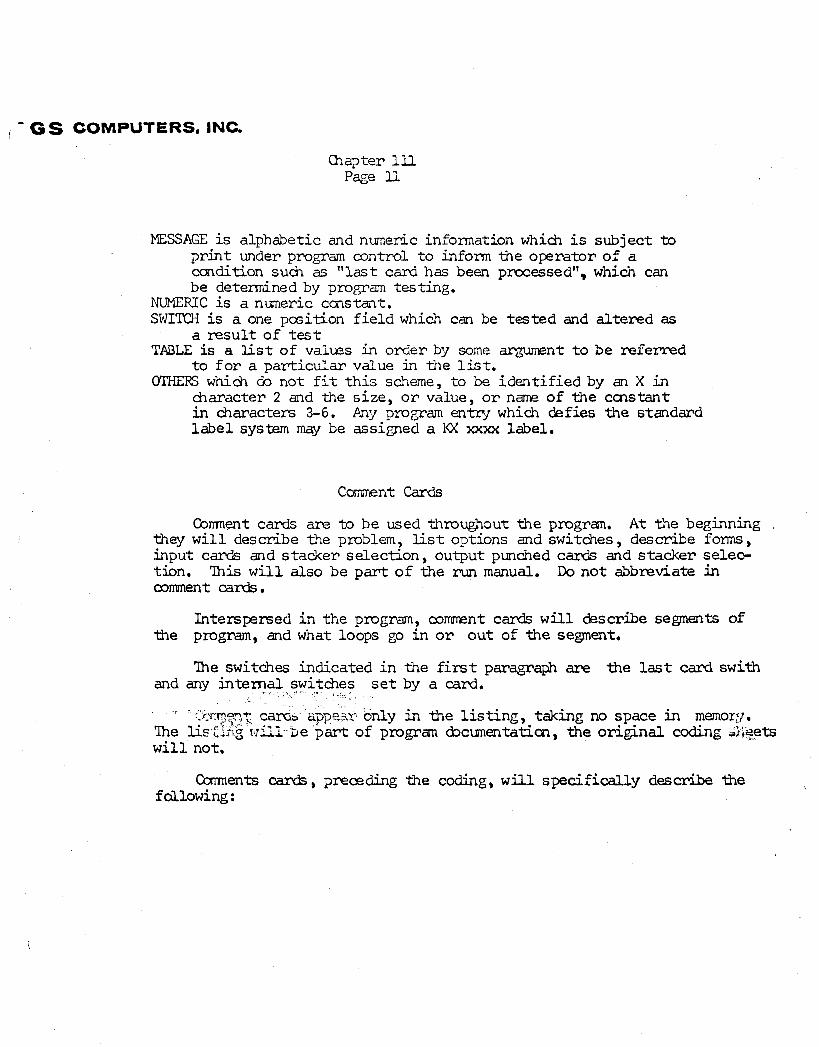
MESSAGE is alphabetic and numeric information which is subject t o pr in t under program control t o inform the operator of a ccndition such as " l a s t card has been pracessedVV, which can be determined by propam testing.
NUMERIC is a numeric cms tat. SWITCH is a one pcsition f i e l d which can be tested and al tered as
a r e s u l t of t e s t TABLE is a List o f valws in order by some a q g m n t t o be r e f e m d
t o f o r a par t icular value in the list. O'IFIERS which ds not f i t t h i s scheme, t o be ident i f ied by an X i n
h a r a c t e r 2 and the s i ze , o r value, o r name of the ccnstant i n character; 3-6. Any p ropam en-] whi& defies the standard l a b e l system may be assigned a KX xxxx label.
Canrent Cards
Comnent cards are to be used throughout the progran. A t the beginning they w i l l describe the problem, List options and switches, describe forms, input cards and stacker select ion, output punched cards and stacker selec tion. 'his w i l l a lso be p a r t o f the run manual. Do not abbreviate in mmment cards.
Interspersed i n the program, o o m n t cards w i l l describe segments of the program, and what loops go in o r ou t of the segment.
Tne switches indicated i n the f irst paragraph me the l a s t card swith and any internal switches s e t by a card,
. * I s l . ,
" " <--t cam, iippep.a~- only in the l i s t i n g , taking no space in menor:!. ?he l i e i s g I:%. ae pa r t of program &cmentaticn, the or ig ina l coding &;i?,eets w i l l not.
Carmen* cards, preceding the coding, w i l l specif ical ly describe the fallowing :

4 0 S COMPUTERS, INC. I
Chapter 111 Page 12
(1) Each routine represented by a macro flow char t symbol. (2 Special programming and mamematical techniques. ( 3 ) Each phase o f a multi-phase program, summarizing the
purpose and rela t ionship, (4) S i p p i f i c m t input , output, work areas. (5) Decision, c c n t m l and exception processing (6 ) 'Ihe f i rs t page o f coding w i l l contain the following information:
Program name and number Programmer n m Brief description of problem Brief description o f p r o m Formulas Special codes Special ins t ruct ions Input and o i ~ t p u t devicec used Ident i f ica t ion o f input Ident i f ica t ion o f output Restar t address Messages, cause and slnnary o f m r r e c t i v e act ion High-order posi t ion o f m e n o r y used Console s e t t i n g Estimated avemge m time
Program Testing
Program Test'r.; Z y s < i i l -'-;rc 2.3 questions: Have w e met the job re- quirements? F i a k 5.:e made ar: r - ~ ~ ? a t e t rans la t ion i n progrwnming? Testing . - is cbne f o r ( ij ?;:::-I__++ -such as wring keypunching, i n c o m c t constme-, insuf f ic ien t area m d co&ter capacity; (2 ) i n t e rp re t ive emrs i n mding from the flw chart; ( 3 ) l o g i c e m r s in the flow char t ; (4) v a l i d i t y e m = i n the or ig ina l mckrstanding and statement of the problem.
Clerical errors plague us all m d can b e s t be eliminated by careful wr i t ing and thorough preliminary planning o f all t h e f ac to r s involved i n arithmetic, s tomge , ed i t i ng and printing.
biGS COMPUTERS, INC. Chapter I l l Page 13
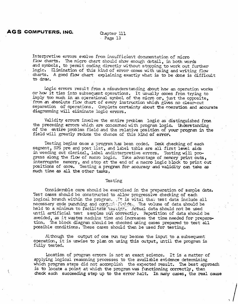
Interpretive e m r s ewlve from insuff ic ient documentation of micro flow charts. The micro chart should show enough de ta i l , in both words and symbols, t o permit coding direct ly without stopping t o work out fur ther logic. Elimination of t h i s kind of e r ro r comes with using and writing flow charts. A good f l aw chart explaining exactly what is to be done is d i f f i c u l t to draw,
b g i c e m r s result f r o m a misunderstanding about how an operation works o r how it t i e s in to subsequent operations. I t usually mmes from trying t o imply too much in an o p r a t i o n a l symbol of the miam o r , , jus t the opposite, from an absolute f l cw chart of every instruction which glves no clear-cut separation of operations. Complete certainty about the me rat ion and accurate diagmmming w i l l eliminate logic errors ,
Validity errors inmlve the ent i re problem log ic as distinguished fm the preceding errors which are concerned with program logic, Understanding of the en t i r e problem f i e l d and the re la t ive position of your propam in the f i e l d w i l l greatly ~ c l u c e the chance of t h i s kind of error,
Testing begins once a pmpm has been coded, Desk checking of each segment, SPS pre and post l ist, and label table are all f i r s t level aids in weeding out c ler ica l , label andinterpretive emom, Testing w i l l pro- gress along -the f l a ~ of macro logic. Take advantage of memry p r in t outs , interrogate memory, and s top a t the end of a macro log ic block to p r i n t out positions of core, Testing a program f o r accuracy and validity can take as mu& time as all the o ~ e r tasks,
Testing
Considerable care should be exercised in the preparation of sample data. Test cases should be mnstmcted t o allow progressive checking of each logical branch within the program, ..T+ is v i t a l thari test data include all necessary code punding and conTi . C1S , , The wlune of data should be held to a minimum t o f a c i l i t ~ r e " 1 i ~ +,?p: dual data should not be used u n t i l d f i c i a l test samples 16 correctly. Repetition of data should be avoided, as it wastes machine time and increases the time needed f o r prepara- t ion, The block diagram slaould be checked using cases prepared t o t e s t all pmsible conditions. These cases should then be used f o r test ing,
AlthouErjn the output of one run my b e a m the input t o a subsequent operation, it is unwise t o plan on using t h i s output, u n t i l the program is fu l ly tested,
location of program errors is not an exact science. It is a matter of applying logica l reasoning processes t o the available evidence determining which program steps did not acmmplish the expected resul t . The bes t approach
\ is to b c a t e a point a t which the program was functioning correctly, then check each succeeding s tep up the e r ro r ha l t , I n many cases, the real cause
1 -G S COMPUTERS, INC.
Chapter ll1 Page 1 4
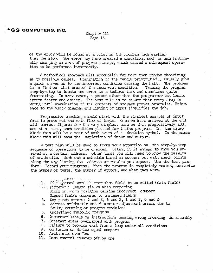
of the e r ro r w i l l be found a t a point in the propam m& e a r l i e r than the stop. The e r r o r may have created a a n d i t i o n , such as unintention- a l ly changing an area of program storage, which caused a subsequent opera- tion t o be performed incorrectly.
A methodical approach w i l l accomplish far more than rancbm theorizing as t o possible causes. Examination of the m m r y printout w i l l usually give a quick answer as t o ~e incorrect condition causing the h a l t , The problem is -to find ou t what created the inmrrec t condition. Tracing the program stepby-step t o locate the e m r is a tedious task a d s m t i m e s quite frustrating. In rnanv cases , a person o the r than the pro&rammer can locate errors f a s t e r and easier. The bes t n i l e is t o assure t h a t every s tep is wrCmg u n t i l examination of the contents of storage proves otherwise. k f e r - ence t o the b h c k diagram and l i s t i n g of input simplifies the job.
Progressive checking s b u l d start with the simplest exanple of input chta t o pmve out the main Elm of lop,ic, Once w e have arrived a t the end with correct figures f o r the very simplest case we then progressively add, one a t a time, each c a d i t i o n planned f o r inl,the program. In the micro block this w i l l be a t e s t of both exi ts of a decision symbol. In the macro block t h i s w i l l show the variations of input and output.
A t e s t plan w i l l be used to focus your at tent ion on the s tepby-step sequence of operations t o be checked. Often, it is enough t o know you a~ rived a t a cer ta in address, Other times you w i l l need t o know the results of arithmetic. Work out a schedule based on success but with b e c k points along the w q l i s t i n g the address o r results you expect. Use -the test plan form, Record your progress. When the propun is completely tested, summarize the nwnber of t e s t s , the number of e r rors , and what they w e r e .
_ I .
. h 1 '
t- .i . i c r
:,.* r ~~~-1tr01 w o n i , ' . l7ter than f i e l d to be edi ted ( data f i e ld ) D i f few:.[ : length f ie lds when canparing Sidk ?~i.% -sit ion causing inmrrect canpare Signed f i e lds compared to unsigned f i e lds Key punch errors : 2 and Z , 5 and S, 1 and I, 0 and 0 Address arithmetic and character adjusment errors due t o faul ty counting o r promam revisions Underfined symbolic operands Incorrect labels on instructions causing wrong indexing in assembly Qnstant areas overlapped with program N u r e t o provide e x i t from a loop under all cmditions Confusion on Hi-lm-equal compare Arithmetic overflow Loop control counter off by one
AG S COMPUTERS, INC. Chapter 1ll Page 15
The following bcuments w i l l be complete, accurate, and available before any test data is run.
Flow charts Card, storage and p r i n t layouts Carriage control tape Operating instruct ion Sanple output data Ut i l i ty mutines nee&d Test data Test plan Source deck o r object deck f o r test
Recommended


![€¦ · [ntroducttonu The recent dtscovety cff ccnvecjve subsuŸ[face afr[flcw wöíi[hjn unsaturated planetan/ sctls ptovtdes for first tnsüghf:s atmcsphere-soö]](https://img.pdfslide.us/doc/110x75/5f9e74215deaa357e77ad407/ntroducttonu-the-recent-dtscovety-cff-ccnvecjve-subsuface-afrflcw-wihjn.jpg)