1Presentation_ID © 1999, Cisco Systems, Inc.
Introductions to ISPDesign FundamentalsIntroductions to ISP
Design Fundamentals

2Presentation_ID © 1999, Cisco Systems, Inc. www.cisco.com
AgendaAgenda
• Rational Behind ISP Network Design
• Point of Presence Topologies
• Adding Services to the Architecture
• Impact of Services on the Network

3Presentation_ID © 1999, Cisco Systems, Inc.
Rational Behind ISPNetwork Design
Rational Behind ISPNetwork Design
Layers upon Layers upon Layersupon Layers …...
Layers upon Layers upon Layersupon Layers …...
3Presentation_ID © 1999, Cisco Systems, Inc. www.cisco.com

4Presentation_ID © 1999, Cisco Systems, Inc. www.cisco.com
The Free On-line Dictionaryof Computing
The Free On-line Dictionaryof Computing
Architecture: Design; the waycomponents fit together;
it may also be used for anycomplex system, e.g. “software
architecture”, “networkarchitecture”

5Presentation_ID © 1999, Cisco Systems, Inc. www.cisco.com
Network Design andArchitecture…
Network Design andArchitecture…
• … can be critical
• … can contribute to the successof the network
• … can contribute to the failureof the network

6Presentation_ID © 1999, Cisco Systems, Inc. www.cisco.com
“
”
No amount of magicknobs will save a
sloppilydesigned network
Paul Ferguson—Consulting Engineer,Cisco Systems
Ferguson’s Law ofEngineering
Ferguson’s Law ofEngineering
7Presentation_ID © 1999, Cisco Systems, Inc. www.cisco.com
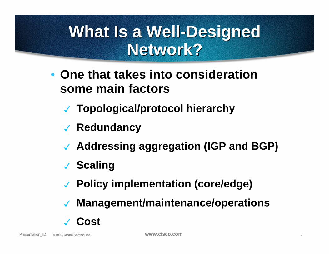
What Is a Well-DesignedNetwork?
What Is a Well-DesignedNetwork?
• One that takes into considerationsome main factors
3 Topological/protocol hierarchy
3 Redundancy
3 Addressing aggregation (IGP and BGP)
3 Scaling
3 Policy implementation (core/edge)
3 Management/maintenance/operations
3 Cost

8Presentation_ID © 1999, Cisco Systems, Inc. www.cisco.com
One Must Acknowledge that…One Must Acknowledge that…
• Two different worlds exist
3One world revolves around privateorganizational networks and anotherconcerns the global Internet
• Growth in the Internet is faster thanany other technology introduced tothe public-at-large

9Presentation_ID © 1999, Cisco Systems, Inc. www.cisco.com
Source: Forbes Magazine July 7th—1997
Internet
CellPhone
PC
TV
Radio
MicrowaveMicrowave
VCR
Airplane
TelephoneTelephone
Car
Electricity
Technology AdoptionTechnology Adoption

10Presentation_ID © 1999, Cisco Systems, Inc. www.cisco.com
“
”
If you’re not scared yet,you don’t understand the
problem!Mike O’Dell—Chief Scientist,
UUnet
Scaling is the #1 Problem onthe Internet
Scaling is the #1 Problem onthe Internet

11Presentation_ID © 1999, Cisco Systems, Inc. www.cisco.com
Core Influences to ISP DesignCore Influences to ISP Design
• Modular Design
• Functional Design
• Tiered/Hierarchical Design
• Multiple Levels of Redundancy
• Routing Protocol Hierarchy
• Build for IP Forwarding First - thenadd services

12Presentation_ID © 1999, Cisco Systems, Inc. www.cisco.com
Modular DesignModular Design
Backbone linkto another PoP
Backbone linkto another PoP
Nx64 customeraggregation layer
Nx64 leased line circuit deliveryChannelised T1/E1 circuits
T1/E1 leased line circuit deliveryChannelised T3/E3 circuits
NetworkOperations
Centre
Consumer
DIAL Access
Other ISPs
Consumer Cable
and xDSL Access
NetworkCore
ISP Services(DNS, Mail, News,
FTP, WWW)
Hosted Services
NxT1/E1 customeraggregation layer
Organize the Networkinto separate andrepeatable modules
3 Backbone
3 POP
3 Hosting Services
3 ISP Services
3 Support/NOC

13Presentation_ID © 1999, Cisco Systems, Inc. www.cisco.com
Functional DesignFunctional Design
• One Box cannot do everything! (no materhow hard people have tried in the past)
• Each router/switch in a network has awell-defined set of functions.
• The various boxes each with afunction interact with each other.
• ISP Networks are a systems approachto design.
14Presentation_ID © 1999, Cisco Systems, Inc. www.cisco.com
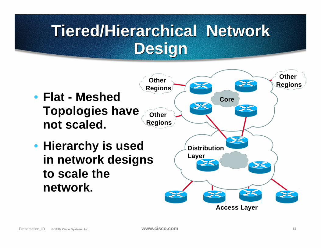
Tiered/Hierarchical NetworkDesign
Tiered/Hierarchical NetworkDesign
Access Layer
DistributionLayer
Other Regions
Other Regions
Other Regions
Core• Flat - MeshedTopologies havenot scaled.
• Hierarchy is usedin network designsto scale thenetwork.

15Presentation_ID © 1999, Cisco Systems, Inc. www.cisco.com
Intra-POP Interconnect
Border
Backbone
Access
Multiple Levels of RedundancyMultiple Levels of Redundancy
• Triple Layered POPRedundancy
3 Lower-level failures are better
3 Lower-level failures may triggerhigher-level failures
3 L2: Two of everything at
3 L3: IGP and BGP provideredundancy and load balancing
3 L4: TCP re-transmissionsrecovers during the fail-over
POP IntraconnectPOP Intraconnect

16Presentation_ID © 1999, Cisco Systems, Inc. www.cisco.com
Multiple Levels of RedundancyMultiple Levels of Redundancy
PoP
BackbonePeer
Networks
Residential Access
LocationAccess
• Objectives -
3 As little user visibility of a fault as possible
3 Minimize the impact of any fault in any part of thenetwork.
3 Network needs to handle L2, L3, L4, and Routerfailure

17Presentation_ID © 1999, Cisco Systems, Inc. www.cisco.com
Hierarchy of RoutingProtocols
BGP4and OSPF/ISIS
FDDI
Other ISPs
CustomersLocalIXP
BGP4 Static/BGP4
BGP4
18Presentation_ID © 1999, Cisco Systems, Inc. www.cisco.com
WarningWarning
“
”
Beware Block Diagram/SlidewareDesign Gurus! They have gottenpeople and networks into trouble
- including Cisco
19Presentation_ID © 1999, Cisco Systems, Inc.
Point of PresenceTopologies
Point of PresenceTopologies
19ISP/IXP Workshops © 1999, Cisco Systems, Inc. www.cisco.com

20Presentation_ID © 1999, Cisco Systems, Inc. www.cisco.com
PoP DesignPoP DesignCore Backbone
Routers
POPInterconnect
Medium
NeighboringPOP
NeighboringPOP
Dedicated Access PSTN/ISDN
Core 1 Core 2
SW 1 SW 2
Access 1 Access 2 NAS 1 NAS 2
External BGP Peering

21Presentation_ID © 1999, Cisco Systems, Inc. www.cisco.com
45 Mb/s HSSI
FDDI
InternetInternetBackboneBackbone
Early Internet POPArchitecture - NSPEarly Internet POPArchitecture - NSP
3Backbone trunksat 45 Mb/s
3Shared mediainterconnectwithin POP:
FDDI, Ethernet, SwitchedEthernet
3ConventionalT3 backboneInternet router

22Presentation_ID © 1999, Cisco Systems, Inc. www.cisco.com
155 Mb/sPOS/ATM
XX
Internet Internet BackboneBackbone
3Backbone trunksat 155 Mb/s
Packet over SONET OC3
ATM OC3
3Switched interconnectwithin POP:
Switched FDDI/Fast Ethernet
ATM OC3
3Advanced OC3 backboneInternet router
Internet POP Architecture -‘96/’97
Internet POP Architecture -‘96/’97

23Presentation_ID © 1999, Cisco Systems, Inc. www.cisco.com
622 Mb/sPOS/ATM
622 Mb/s ATM1 Gb/s Ethernet
Duplex Fast E, 155/ 622 Mb/s ATM, or1 Gb/s Ethernet
InternetInternetBackboneBackbone
3 Backbone trunks at622 Mb/s
Packet over SONET OC12ATM OC12
3 Switched interconnectwithin POP:
ATM at OC3 AND OC12Ethernet ChannelGigabit Ethernet (early ’98)POSIP (late ‘98)
3 Gigabit OC12 backboneInternet router
Internet POP Architecture -‘97/’98
Internet POP Architecture -‘97/’98

24Presentation_ID © 1999, Cisco Systems, Inc. www.cisco.com
• SRP Rings - High Speedof SDH combined with fastfailover and redundancy
3High bandwidth
3Reduced port counts
3Reduced complexity
3Proactive self healing
Backbone
7xxx
GSRGSR
7xxx
7xxx
7xxx
7xxx
leased line aggregation
Internet POP Architecture -‘99/’01
Internet POP Architecture -‘99/’01

25Presentation_ID © 1999, Cisco Systems, Inc. www.cisco.com
Large POPs - add a 3rd layerLarge POPs - add a 3rd layer
Internet Internet BackboneBackbone
3 Problem: port density!
3 Solution: buy more routers!
3 Customer routers connect toaggregation routers
Packet over SONET OC3
ATM OC3
3 Aggregation routers connect tobackbone routers
3 Scales nicely
3 X CRs to Y ARs to Z BRs
3...where X>Y>Z
3Be careful not tooversubscribe!
OC3
OC12
OC48

26Presentation_ID © 1999, Cisco Systems, Inc. www.cisco.com
FDDI100Mbps
POSN x 155
SRP2 x 622Mbpsor 2x2.5GB
Fast/Gig Ethernet100/1000Mbps
POP Interconnect SummaryPOP Interconnect Summary

27Presentation_ID © 1999, Cisco Systems, Inc. www.cisco.com
Key Design Principles
• Interconnection forManagement, Security,and Accounting services
3 Netflow Devices -FlowCollector
3 Syslog collector for allnetwork devices
3 SNMP collector (PC BasedUNIX)
3 Security Auditing Tools(NetSonar)
POS
POS & ATM for Core Backbone
GSRGSR
75077507
Customer and Services
Management
&
Accounting

28Presentation_ID © 1999, Cisco Systems, Inc. www.cisco.com
ISP routing Architectures - IPISP routing Architectures - IP
• IGP = EIGRP, IS-IS,or OSPF
3 almost always IS-IS or OSPF
3 IS-IS, single level (usually L2)
3 OSPF, either single area or BB/POPareas
• BGP = all routers in full mesh
3 mesh accomplished with routereflectors, confederations, actual fullmesh
• All routers have all routes, soservices could go anywhere

29Presentation_ID © 1999, Cisco Systems, Inc. www.cisco.com
ISP routing Architectures -IP+MPLS
ISP routing Architectures -IP+MPLS
• IGP = EIGRP, IS-IS,or OSPF
3 must be IS-IS or OSPF to use MPLSTE
• BGP = only edge routers need full routes
3 full-mesh of edge routers usingaforementioned mechanisms
3 packets are forwarded via LDPlabels, not IP destination address
• Where to put your services?
3 cannot hang a cache service off of arouter that doesn’t have full routes!

30Presentation_ID © 1999, Cisco Systems, Inc.
Adding Services to theArchitecture
Adding Services to theArchitectureCause and EffectCause and Effect
3015030925_04F9_c1 © 1999, Cisco Systems, Inc.

31Presentation_ID © 1999, Cisco Systems, Inc. www.cisco.com
Services?How many Services?
Services?How many Services?
Edge (one-time) services
• Voice over IP
• MPLS VPNs
• CDNs
• VPDNs
• Managed services
• Dial—DSL—cable
Per-hop services
• MPLS packet forwarding
• DiffServ, other QoS
• Multicast Services
Most network services are applied at the edge!

32Presentation_ID © 1999, Cisco Systems, Inc. www.cisco.com
Ask the Right QuestionsAsk the Right Questions
• What is the value of the service?
3 Technical merit
3 Cost savings
3 Marchitecture
• What is the cost of the service?
3 Equipment?
3 Training people to support it?
3 Network buildouts/topology changes?

33Presentation_ID © 1999, Cisco Systems, Inc.
Impact of Services onthe Network
Impact of Services onthe Network
3315030925_04F9_c1 © 1999, Cisco Systems, Inc.

34Presentation_ID © 1999, Cisco Systems, Inc. www.cisco.com
Who Knows?Who Knows?
• What will be the impact on existing trafficloads/patterns?
• Can the network deliver the performancethat your customers/applications desire?delay? jitter (delay variation)?
• Make sure to add capacity as you addservices - bandwidth is a must.

35Presentation_ID © 1999, Cisco Systems, Inc. www.cisco.com
Deployment of New ServicesDeployment of New Services
• Is more of a business decision
• The technical aspect is to ensurecontinued network performance—scalability and stability
• Try to keep services within your AS
3end2end control
3less likelihood of failure/flaps

36Presentation_ID © 1999, Cisco Systems, Inc. www.cisco.com
Deploying New ServicesDeploying New Services
• Don’t feed the hype fire
• Look before you leap!
• Don’t deploy new technologies andservices just for the sake of it; havevalid business and technical reasons

37Presentation_ID © 1999, Cisco Systems, Inc. www.cisco.com
Deploying New ServicesDeploying New Services
• Usually a Service requires a TCP/UDPtermination (I.e. TCP’s three wayhandshake)
• Termination should happen out sideof the primary flow path
• Otherwise, the network is thendesigned around the single service.

38Presentation_ID © 1999, Cisco Systems, Inc. www.cisco.com
Deploying New ServicesDeploying New Services
CPECPE POPPOP CORECORE
MultiplePOP Services
Interconnect Leased Core
ISDNPOTS
Lease LineCablexDSL
Access
Primary Packet Flow
ServiceTerminate
Here

39Presentation_ID © 1999, Cisco Systems, Inc.
TransparentRedirection of a Flow
in the POP
TransparentRedirection of a Flow
in the POPFactors that went into the
design of WCCPFactors that went into the
design of WCCP
39Presentation_ID © 1999, Cisco Systems, Inc. www.cisco.com

40Presentation_ID © 1999, Cisco Systems, Inc. www.cisco.com
Design Objectives for the ISPDesign Objectives for the ISP
• Transparent Redirection of a IP flowbased on source, destination, and/orport number.
• Transparent Integration - norebuilding the POP to add thisservice.
• Failed open - if the service fails, itshould not effect the core IP servicenor any other services.

41Presentation_ID © 1999, Cisco Systems, Inc. www.cisco.com
Design Objectives for the ISPDesign Objectives for the ISP
CPECPE POPPOP CORECORE
Interconnect Leased Core
ISDNPOTS
Lease LineCablexDSL
Access
Primary Packet Flow
WCCPServiceClusters
• Not to effect the primary packet flow of thePOP - if not redirected - then is CEF/dCEFSwitched!

42Presentation_ID © 1999, Cisco Systems, Inc. www.cisco.com
Design Objectives for the ISPDesign Objectives for the ISP
CPECPE POPPOP CORECORE
Interconnect Leased Core
ISDNPOTS
Lease LineCablexDSL
Access
WCCPServiceClusters
• Work with the multi-level L2/L3 redundancyof the ISP POP. Equal paths in the IGP +CEF leads packet asymmetry.
Input PortWCCP
Redirect

43Presentation_ID © 1999, Cisco Systems, Inc. www.cisco.com
Design Objectives for the ISPDesign Objectives for the ISP
CPECPE POPPOP CORECORE
Interconnect Leased Core
ISDNPOTS
Lease LineCablexDSL
Access
WCCPServiceClusters
• Provide the ISP with Flexibility on the pointof redirection. Do not force an architectureon the customer.

44Presentation_ID © 1999, Cisco Systems, Inc. www.cisco.com
Design Objectives for theService Group
Design Objectives for theService Group
• Linear Scalability with the Cache -minimize object replication.
• Fault Tolerance and Maintenance.
• “Joe Smith the Telco Tech” test.

45Presentation_ID © 1999, Cisco Systems, Inc. www.cisco.com
Recommended