Disclosure to Promote the Right To Information
Whereas the Parliament of India has set out to provide a practical regime of right to information for citizens to secure access to information under the control of public authorities, in order to promote transparency and accountability in the working of every public authority, and whereas the attached publication of the Bureau of Indian Standards is of particular interest to the public, particularly disadvantaged communities and those engaged in the pursuit of education and knowledge, the attached public safety standard is made available to promote the timely dissemination of this information in an accurate manner to the public.
इंटरनेट मानक
“!ान $ एक न' भारत का +नम-ण”Satyanarayan Gangaram Pitroda
“Invent a New India Using Knowledge”
“प0रा1 को छोड न' 5 तरफ”Jawaharlal Nehru
“Step Out From the Old to the New”
“जान1 का अ+धकार, जी1 का अ+धकार”Mazdoor Kisan Shakti Sangathan
“The Right to Information, The Right to Live”
“!ान एक ऐसा खजाना > जो कभी च0राया नहB जा सकता है”Bhartṛhari—Nītiśatakam
“Knowledge is such a treasure which cannot be stolen”
“Invent a New India Using Knowledge”
है”ह”ह
IS 12032-8 (1987): Graphical symbols for diagrams in thefield of electrotechnology, Part 8: Measuring instruments,lamps and signalling devices [ETD 1: Basic ElectrotechnicalStandards]

IS : 12032 ( Part 8 ) - 1987 UDC 621-3-061 : 003.62 IEC Pub 617 - 8 ( 1983 )
Indian Standard
GRAPHICAL SYMBOLS FOR DIAGRAMS IN THE FIELD OF ELECTROTECHNOLOGY
PART 8 MEASURING INSTRUMENTS, LAMPS AND SIGNALLING DEVICES
( IEC Title : Grhphical Symbols for Diagrams - Part 8 : Measuring Instruments, Lamps and Signalling Devices )
National Foreword
This Indian Standard ( Part 8 ) which is identical with IEC Pub 617-8 (1983) (Graphical symbols for diagrams - Part 8 : Measuring instruments, lamps and signalling devices’; issued by the International Electrotechnical Commission ( IEC ), was adopted by the Bureau of Indian Standards on the recommen- dation of the Basic Electrotechnical Standards Sectional Committee and approval of the Electrotechnical Division Council.
Cross Reference
International Standard Corresponding Indian Standard
IEC Pub 27 Letter symbols to be used in electrical IS : 3722 Letter symbols and signs used in technology electrical technology ( in 2 Parts )
IEC Pub 617-2 (1983) Graphical symbols for dia- IS : 12032 ( Part 2 )-1987 Graphical symbols grams - Part 2 : Symbol elements, qualifying for diagrams in the field of electrotech- symbols and other symbols having general nology : Part 2 Symbol elements, qualify- application ing symbols and other symbols having
general application
Adopted 18 June 1987 I
0 November 1988, BIS 1
Gr 7
BUREAU OF INDIAN STANDARDS MANAK BHAVAN, 9 BAHADUR SHAH ZAFAR MARG
NEW DELHI 110002

As in the Original Standard, this Page is Intentionally Left Blank

IS : 12032 (Part S)-1987 IEC Pub 617-8 (1983)
SECTION 1 - INDICATING, RECORDING AND INTEGRATING INSTRUMENTS, GENERAL SYMBOLS
1.1 The asterisk within the symbols of this section shall be replaced with one of the following:
- the letter symbol for the unir of the quantity measured, or a multiple or sub-multiple thereof (see examples 08-02-01 and 08-02-07);
- the letter symbol for the quantity measured (see examples 08-02-05 and 08-02-06);
- a chemical formula (see example 08-02-13);
- a graphical symbol (see example 08-02-08).
The symbol or formula used should be related to the information displayed by the instrument regardless of the means used to obtain the information.
1.2 Letter symbols for units and for quantities shall be selected from one of the parts of IEC Publication 27: Letter Symbols to be Used in Electri- cal Technology.
Provided IEC Publication 27, or the letter symbols for chemical elements, do not apply, other letter symbols may be used, if they are explained on the diagram or in referenced documents.
1.3 If the letter symbol for the unit of the quantity measured is used, it may be necessary to show the letter symbol for the quantity, as supplemen- tary information. It should be placed below the unit letter symbol (see example 08-02-02).
Supplementary information concerning the quantity measured, and any necessary qualifying symbol may be shown below the quantity letter symbol.
1.4 If more than one quantity is indicated or recorded by an instrument, the appropriate symbol outlines shall be placed attached in line, horizon- tally or vertically (see examples 08-03-02 and 08-04-14).
3

IS : 12032 (Part 8)-1987 IEC Pub 617-8 (1983)
I-
n
No.
M-01-01
Symbol
0 *
Description
Indicating instrument
The asterisk shall be replaced in accordance with the rules given in Clause 1.1
0fUI1-02
cl t
Recording instrument
The asterisk shall be replaced in accordance with the rules given in Clause 1.1
t#1-01-03 Integrating instrument Energy meter
The asterisk shall be replaced in accordance with the rules given in Clause 1.1
Notes 1. - The symbol may also be used for a remote instrument which repeats a reading transmit- ted from an integrating meter. For example, see symbol O&04-1 1.
2. - The outline may be combined with that for a recording instrument to represent a com- bined instrument. For example, see symbol 08-04-14.
3. - Symbols from Section 5 of IEC Publication 617-2: Graphical Symbols for Diagrams, Part 2: Symbol Elements, Qualifying Sym- bols and Other Symbols Having General Application, may be used to specify the direction of energy flow. For examples, see symbols OgO4-04 to 0&04M.
4. - The number of rectangles at the top of the symbol indicates the number of different summations by a multirate meter. For example, see symbol Ol3-04-Ot3.
4

IS : 12032 (Part Q-1987 IEC Pub 617-8 (1983)
SECTION 2 - EXAMPLES OF INDICATING INSTRUMENTS
No.
08-02-01
Symbol
0 V
Voltmeter
Description
08-02-02 Reactive current ammeter
08-02-03 Maximum demand indicator actuated by an integrating meter
08-02-04
0 Varmeter
var
08-02-05
0 cos cp
Power-factor meter
o8-02-Q6
0 cp
Phase. meter
OS-0247
0 Hz
Frequency meter
0842-08 Synchronoscope
08-02-09
0 h
Wavemeter
0842-10 Oscilloscope
5

IS : 12032 (Part Q-1987 IEC Pub 617-8 (1983)
No. Symbol
ofM2-11 V 0 Ud
0 NaCl
0 n
Description
Differential voltmeter
Galvanometer
Salinity meter
Thermometer Pyrometer
Nore. - 0 may be replaced by r”.
1
SECTION 3 - EXAMPLES OF RECORDING INSTRUMENTS
No. Symbol Description
! Recording wattmeter
Combined recording wattmeter and varmeter
Oscillograph
6

IS : 12032 (Part 8)-1987 IEC Pub 617-8 (1983)
SEffION 4 - EXAMPLES OF INTEGRATING INSTRUMENTS
No.
D8-04-01
S~bOl
B
h
Hour meter
Description
Lx?-04-m -P
5 Ah
Ampere-hour meter
D&04-03
R
Wh
Watt-hour meter
08-04-04
.B Wh
Watt-hour meter, measuring energy transmitted in one
direction only
08-04-05
B Wh
Watt-hour meter, measurmg the energy flow from the
busbars
1
08-04-06
n Wh
Watt-hour meter, measuring the energy flow towards
the busbars
cm-04-07
n Wh
Import-export watt-hour meter
I3 Wh
Multi-rate watt-hour meter, two-rate shown
Excess watt-hour meter
7

IS : 12032 (Part 8)-1987 IEC Pub 617-8 (1983)
No.
C&04-10
Description
Watt-hour meter with transmitter
o&04-11 Remote meter (repeater) actuated by a watt-hour meter
o&04-12 Remote meter (repeater) with printing device, actuated by a watt-hour meter
Watt-hour meter with maximum demand indicator
o&04-14 Watt-hour meter with maximum demand recorder
Og-04”15
0
varh
Var-hour meter
8

IS : 12U32 (Part Q-1987 IEC Pub 617-8 (1983)
SECTION 5 - COUNTING DEaCES
No.
O&05-01
Symbol
Use symbol 02-14-02
Description
Counting function of a number of events, qualifying symbol
Pulse meter (electrically-operated countng device)
@-M-O3
_--
Pulse meter manually pre-set to n (reset if n = 0)
Pulse meter electrically reset to 0
Pulse meter with multiple contacts Respective contacts close once at every unit (109, ten (lo’), hundred (lo*), thousand (10’) events registered
Counting device, cam driven and closing a contact for each n events
9

IS : 12032 (Part 8)-1987 IEC Pub 617-8 (1983)
SECTION 6 - THERMOCOUPLES
No. Symbol Description
WMK5-O1 Form 1 -
V
Thermocouple, shown with polarity symbols
+
08-06-02
.u
Thermocouple with direct indication of polarity, the
Form 2 negative pole being represented by the thick line
0&06-03
x
Thermocouple with non-insulated heating element
NOM. - Symbol 05-07-07 may be used to represent the heating element instead of symbol 05-07-Of~
0%06-04 Slmplifled form
u
08-06-05
u
Thermocouple with insulated heatmg element
The note with symbol 08-06-03 applies
n 08-06-06
Simplified form u
IO
IS : 12032 (Part 8)-1987 IEC Pub 617-8 (1983)
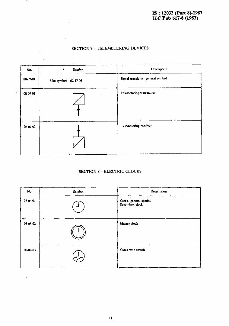
SECHON 7 - TELEMETERING DEVICES
No.
W-07-01
? SphOl
use symbol 02-1746
Description
Signal translator, general symbol
OR0742 Telemetering transmitter
08-07-03 Telemetering receiver
SECTION 8 - ELECTRIC CLOCKS
No.
o%og-ol
SphOl
0 _l
Description
Clock, general symbol Secondary clock
Master clock
0%0&03
0 -I -II
Clock with switch
11
IS : 12032 (Part 8)-1987 IEC Pub 617-8 (1983)
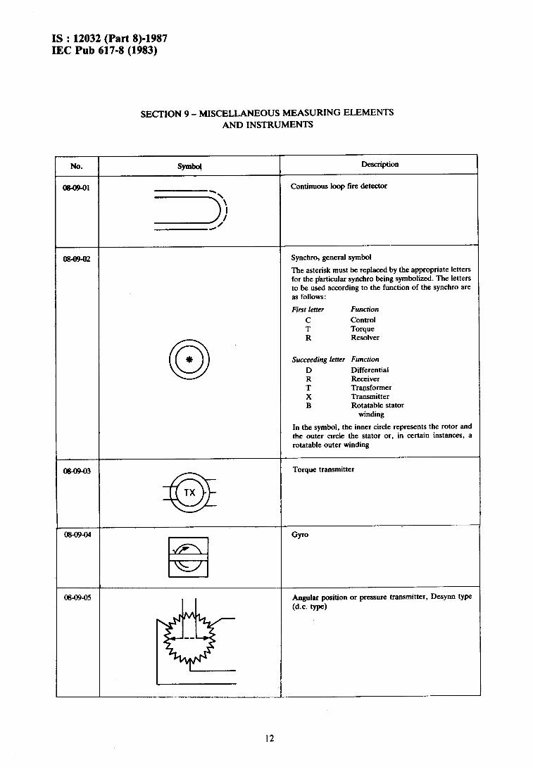
SECI’ION 9 - MISCELLANEOUS MEASURING ELEMENTS AND INSTRUMENTS
0 +
No.
Ot349-01
Description
Continuous loop fire detector
Synchro, general symbol
The asterisk must be replaced by the appropriate letters for the Qarticular synchro being symbolized. The letters to be used according to the function of the synchro are as follows:
First letter FUfKtkM
C Control T Torque R Resolver
Succeeding letter Function
D Differential R Receiver T Transformer X Transmitter B Rotatable stator
winding
In the symbol, the inner circle represents the rotor and the outer arcle the stator or, in certain instances, a rotatable outer winding
a
TX
Torque transmitter
08-0!2-04
El
GP
Angular position or pressure transmitter, Desynn type
(d-c. type)
I
12

IS : 12032 (Part Q-1987 IEC Pub 617-8 (1983)
No.
0&09-06
Symbol Description
’ Angular position or pressure indicator, Desynri type (d.c. type)
08-09-07 Angular position or pressure transmitter, inductor type
0&09-08 Angular position or pressure indicator, inductor type
13
,

IS : 12032 (Part Q-1987 IEC Pub 617-8 (1983)
SECTION 10 - LAMPS AND SIGNALLING DEVICES
No.
3%1041
Description
Lamp, general symbol Signal lamp, general symbol
Notes 1. - If it is desired to indicate the colour, a nota- tion according to the following code is placed adjacent to the symbol: RD =red YE = yellow GN =green BU =blue WH = white
2. - If it is desired to indicate the type of lamp, a notation according to the following code is placed adjacent to the symbol: Ne = neon Xe =xenon Na = sodium vapour Hg =mercury I = iodine IN = incandescent EL = electroluminescent ARC = arc FL = fluorescent IR = infra-red UV = ultra-violet LED = light emitting diode
08-1042
-
-&
Signal lamp, flashing type.
F,
Indicator, electromechanical Annunciator element
v
Electromechanical position indicator with one de-ener- gized (shown) and two operated positions
o&lo-OS Horn
14

IS : 12032 (Part 8)-1987 IEC Pub 617-8 (1983)
.No. Symbol Duaiption
08-10-06 Preferred form
F?
Bcu
08-10-07 Other form
8
08-10-08
f?
single-stroke t+l
08-10-09
6
siren
08-10-10
F7
BIUZU Preferred form
08-10-11 Other form
Q
W-10-12
R
Whistle, electrically operated
15 Reprography Unit, BIS. New Delhi, India
Recommended