PROGRAM
MORE INFO
SCROLLDISPLAY
CHANGEVALUE
TEST DIAGNOSTICS
IQ SYSTEM DISPLAY MODULE (IQDM)
OWNER’S MANUAL
The IQDM is a handheld diagnostic tool for use withClub Car IQ System vehicles. This owner’s manualincludes all information required to operate theIQDM with Club Car IQ System vehicles only, butdoes not contain detailed information for trouble-shooting the vehicle. Refer to the vehicle mainte-nance and service manual and supplement fordetailed vehicle troubleshooting and service proce-dures. For vehicle operation information refer to thevehicle owner’s manual supplied with the vehicle. Ifyou do not have a vehicle owner’s manual or a vehi-cle maintenance and service manual and supple-ment, they may be obtained from your Club Cardealer or distributor.
Manual No. 102249201
For use with Kit No. 102248801
Edition Code 0501B0601A
Page 2 IQDM Service Tool Owner’s Manual
NOTICE
This manual contains proprietary information that is protected by copyright. All rights are reserved. No part ofthis manual may be photocopied, reproduced, or translated to another language without the written consentof Club Car, Inc.
Club Car is not liable for errors in this manual or for incidental or consequential damages that result from theuse of the material in this manual.
The information contained in this document is subject to change without notice.
Club Car reserves the right to make design changes to service tools and vehicles without obligation to makethese changes on units previously sold.
This manual effective June 11, 2001.
©2001 Club Car, Inc.
TABLE OF CONTENTS
Safety Details . . . . . . . . . . . . . . . . . . . . . . . . . . . . . . . . . . . . . . . . . . . . . . . . . . . . . . . . . . . . . . . . . . . . . . . 3
Parts Included in Kit . . . . . . . . . . . . . . . . . . . . . . . . . . . . . . . . . . . . . . . . . . . . . . . . . . . . . . . . . . . . . . . . . . 4
General Information . . . . . . . . . . . . . . . . . . . . . . . . . . . . . . . . . . . . . . . . . . . . . . . . . . . . . . . . . . . . . . . . . . 6
Overview . . . . . . . . . . . . . . . . . . . . . . . . . . . . . . . . . . . . . . . . . . . . . . . . . . . . . . . . . . . . . . . . . . . . . . . . . . 6
Test Menu . . . . . . . . . . . . . . . . . . . . . . . . . . . . . . . . . . . . . . . . . . . . . . . . . . . . . . . . . . . . . . . . . . . . . . . . . 8
Diagnostics Menu . . . . . . . . . . . . . . . . . . . . . . . . . . . . . . . . . . . . . . . . . . . . . . . . . . . . . . . . . . . . . . . . . . . 11
Special Diagnostics Menu . . . . . . . . . . . . . . . . . . . . . . . . . . . . . . . . . . . . . . . . . . . . . . . . . . . . . . . . . . . . . 15
Special Program Menu . . . . . . . . . . . . . . . . . . . . . . . . . . . . . . . . . . . . . . . . . . . . . . . . . . . . . . . . . . . . . . . 16
IQDM Troubleshooting . . . . . . . . . . . . . . . . . . . . . . . . . . . . . . . . . . . . . . . . . . . . . . . . . . . . . . . . . . . . . . . . 22
Test Procedures . . . . . . . . . . . . . . . . . . . . . . . . . . . . . . . . . . . . . . . . . . . . . . . . . . . . . . . . . . . . . . . . . . . . . 24
Safety Details
IQDM Service Tool Owner’s Manual Page 3
SAFETY DETAILS
∆
DANGER
• Battery – Explosive gases! Do not smoke. Keep sparks and flames away from the vehicle andservice area. Ventilate when charging or using in an enclosed space. Wear a full face shieldand rubber gloves when working on or near batteries.
• Use extreme caution when using tools, wires, or metal objects near batteries! A short circuitand (or) spark could cause an explosion.
• Battery – Poison! Contains acid! Causes severe burns. Avoid contact with skin, eyes, orclothing. Antidotes:- External: Flush with water. Call a physician immediately.- Internal: Drink large quantities of milk or water. Follow with milk of magnesia or vegetable
oil. Call a physician immediately.- Eyes: Flush with water for 15 minutes. Call a physician immediately.
∆
WARNING
• The vehicle operator should not monitor the IQDM while the vehicle is in motion. A techniciancan monitor the IQDM while traveling as a passenger in the vehicle. Failure to heed thiswarning could result in severe personal injury or death.
• This owner’s manual should be read completely before attempting to operate the IQDM.Failure to follow the instructions in this manual could result in property damage, severepersonal injury, or death.
• Only trained technicians should repair or service the vehicle. Anyone doing even simplerepairs or service should have knowledge and experience in electrical and mechanical repair.
• Follow the procedures exactly as stated in this manual, and heed all DANGER, WARNING, andCAUTION statements in this manual, as well as those affixed to the vehicle.
• Improper use of the vehicle or failure to properly maintain it could result in decreased vehicleperformance or severe personal injury.
• Any modification or change to the vehicle that affects the stability or handling of the vehicle,or increases maximum vehicle speed beyond factory specifications, could result in severepersonal injury or death.
• Check the vehicle owner’s manual for proper location of all vehicle warning decals and makesure they are in place and are easy to read.
• Wear safety glasses or approved eye protection when servicing the vehicle. Wear a full faceshield and rubber gloves when working on or near batteries.
• Turn key switch OFF and remove key, place Forward/Reverse switch in the NEUTRAL position,and chock the wheels prior to servicing the vehicle.
• Do not wear loose clothing or jewelry such as rings, watches, chains, etc., when servicingvehicle.
• Moving parts! Do not attempt to service the vehicle while it is running.• Use insulated tools when working near batteries or electrical connections. Use extreme
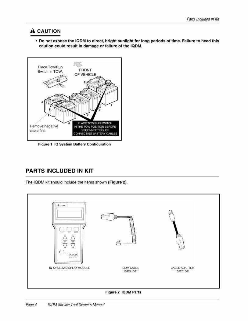
caution to avoid shorting of components or wiring.• To avoid unintentionally starting the vehicle, place the Tow/Run switch in the TOW position,
then disconnect the batteries, negative cable (–) first, as shown in (Figure 1).• After disconnecting the batteries, wait 90 seconds for the controller capacitors to discharge.• If wires are removed or replaced make sure wiring and wire harness are properly routed and
secured. Failure to properly route and secure wiring could result in vehicle malfunction,property damage or personal injury.
Parts Included in Kit
Page 4 IQDM Service Tool Owner’s Manual
∆
CAUTION
• Do not expose the IQDM to direct, bright sunlight for long periods of time. Failure to heed thiscaution could result in damage or failure of the IQDM.
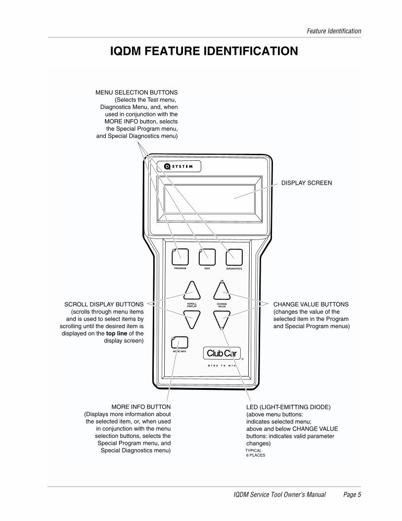
PARTS INCLUDED IN KIT
The IQDM kit should include the items shown
(Figure 2)
.
Figure 1 IQ System Battery Configuration
Figure 2 IQDM Parts
TOWRUN
WARNING
1
2
3
4
6
5
FRONTOF VEHICLE
Place Tow/RunSwitch in TOW.
Remove negativecable first.
PLACE TOW/RUN SWITCH IN THE TOW POSITION BEFORE
DISCONNECTING OR CONNECTING BATTERY CABLES
PROGRAM
MORE INFO
SCROLLDISPLAY
CHANGEVALUE
TEST DIAGNOSTICS
IQ SYSTEM DISPLAY MODULE IQDM CABLE102241501
CABLE ADAPTER102251501
Feature Identification
IQDM Service Tool Owner’s Manual Page 5
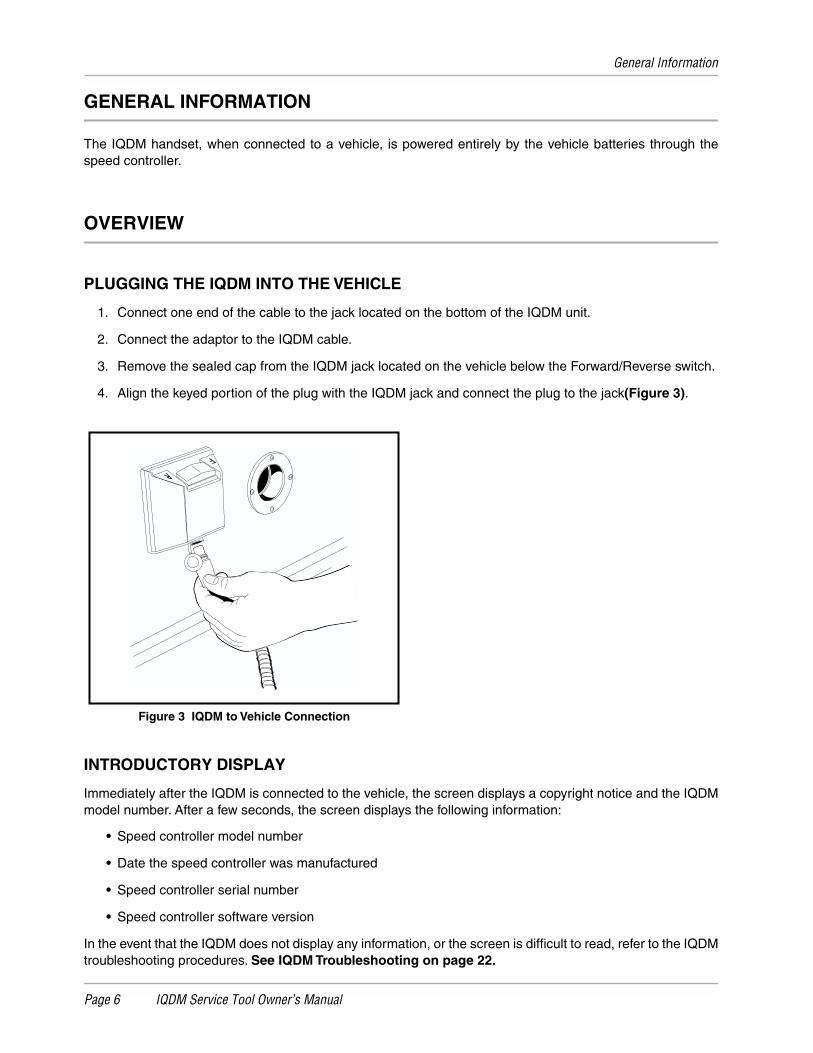
IQDM FEATURE IDENTIFICATION
PROGRAM
MORE INFO
SCROLLDISPLAY
CHANGEVALUE
TEST DIAGNOSTICS
TYPICAL 6 PLACES
DISPLAY SCREEN
CHANGE VALUE BUTTONS(changes the value of theselected item in the Programand Special Program menus)
LED (LIGHT-EMITTING DIODE)(above menu buttons:indicates selected menu;above and below CHANGE VALUEbuttons: indicates valid parameterchanges)
SCROLL DISPLAY BUTTONS(scrolls through menu items
and is used to select items byscrolling until the desired item isdisplayed on the top line of the
display screen)
MENU SELECTION BUTTONS(Selects the Test menu,
Diagnostics Menu, and, whenused in conjunction with theMORE INFO button, selectsthe Special Program menu,
and Special Diagnostics menu)
MORE INFO BUTTON(Displays more information aboutthe selected item, or, when used
in conjunction with the menu selection buttons, selects the
Special Program menu, and Special Diagnostics menu)
General Information
Page 6 IQDM Service Tool Owner’s Manual
GENERAL INFORMATION
The IQDM handset, when connected to a vehicle, is powered entirely by the vehicle batteries through thespeed controller.
OVERVIEW
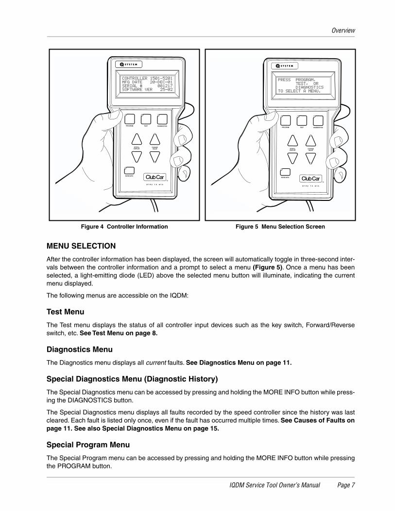
PLUGGING THE IQDM INTO THE VEHICLE
1. Connect one end of the cable to the jack located on the bottom of the IQDM unit.
2. Connect the adaptor to the IQDM cable.
3. Remove the sealed cap from the IQDM jack located on the vehicle below the Forward/Reverse switch.
4. Align the keyed portion of the plug with the IQDM jack and connect the plug to the jack
(Figure 3)
.
INTRODUCTORY DISPLAY
Immediately after the IQDM is connected to the vehicle, the screen displays a copyright notice and the IQDMmodel number. After a few seconds, the screen displays the following information:
•
Speed controller model number
•
Date the speed controller was manufactured
•
Speed controller serial number
•
Speed controller software version
In the event that the IQDM does not display any information, or the screen is difficult to read, refer to the IQDMtroubleshooting procedures.
See IQDM Troubleshooting on page 22.
Figure 3 IQDM to Vehicle Connection
Overview
IQDM Service Tool Owner’s Manual Page 7
MENU SELECTION
After the controller information has been displayed, the screen will automatically toggle in three-second inter-vals between the controller information and a prompt to select a menu
(Figure 5)
. Once a menu has beenselected, a light-emitting diode (LED) above the selected menu button will illuminate, indicating the currentmenu displayed.
The following menus are accessible on the IQDM:
Test Menu
The Test menu displays the status of all controller input devices such as the key switch, Forward/Reverseswitch, etc.
See Test Menu on page 8.
Diagnostics Menu
The Diagnostics menu displays all
current
faults.
See Diagnostics Menu on page 11.
Special Diagnostics Menu (Diagnostic History)
The Special Diagnostics menu can be accessed by pressing and holding the MORE INFO button while press-ing the DIAGNOSTICS button.
The Special Diagnostics menu displays all faults recorded by the speed controller since the history was lastcleared. Each fault is listed only once, even if the fault has occurred multiple times.
See Causes of Faults onpage 11.
See also Special Diagnostics Menu on page 15.
Special Program Menu
The Special Program menu can be accessed by pressing and holding the MORE INFO button while pressingthe PROGRAM button.
Figure 4 Controller Information Figure 5 Menu Selection Screen
PROGRAM
MORE INFO
SCROLLDISPLAY
CHANGEVALUE
TEST DIAGNOSTICSPROGRAM
MORE INFO
SCROLLDISPLAY
CHANGEVALUE
TEST DIAGNOSTICS
Test Menu
Page 8 IQDM Service Tool Owner’s Manual
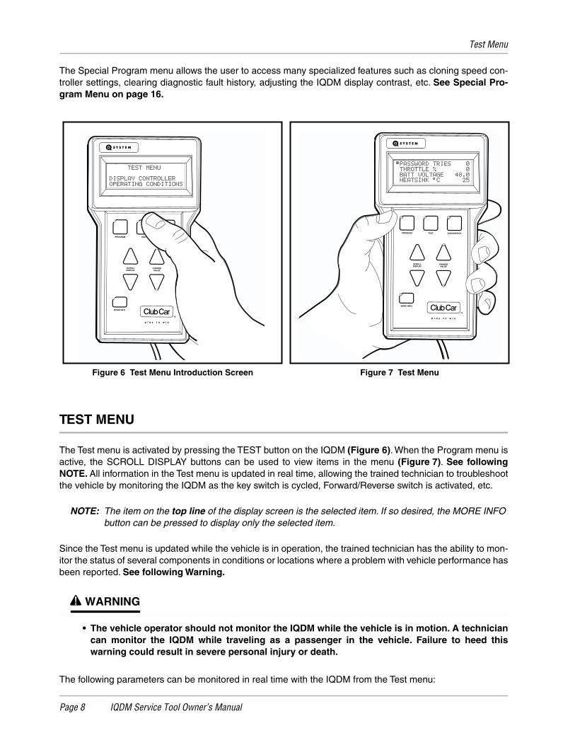
The Special Program menu allows the user to access many specialized features such as cloning speed con-troller settings, clearing diagnostic fault history, adjusting the IQDM display contrast, etc.
See Special Pro-gram Menu on page 16.
TEST MENU
The Test menu is activated by pressing the TEST button on the IQDM
(Figure 6)
. When the Program menu isactive, the SCROLL DISPLAY buttons can be used to view items in the menu
(Figure 7)
.
See followingNOTE.
All information in the Test menu is updated in real time, allowing the trained technician to troubleshootthe vehicle by monitoring the IQDM as the key switch is cycled, Forward/Reverse switch is activated, etc.
NOTE:
The item on the
top line
of the display screen is the selected item. If so desired, the MORE INFO button can be pressed to display only the selected item.
Since the Test menu is updated while the vehicle is in operation, the trained technician has the ability to mon-itor the status of several components in conditions or locations where a problem with vehicle performance hasbeen reported.
See following Warning.
∆
WARNING
• The vehicle operator should not monitor the IQDM while the vehicle is in motion. A techniciancan monitor the IQDM while traveling as a passenger in the vehicle. Failure to heed thiswarning could result in severe personal injury or death.
The following parameters can be monitored in real time with the IQDM from the Test menu:
Figure 6 Test Menu Introduction Screen Figure 7 Test Menu
PROGRAM
MORE INFO
SCROLLDISPLAY
CHANGEVALUE
TEST DIAGNOSTICS
PROGRAM
MORE INFO
SCROLLDISPLAY
CHANGEVALUE
TEST DIAGNOSTICS
Test Menu
IQDM Service Tool Owner’s Manual Page 9
PASSWORD TRIES
An IQDM-P and password is required to place the vehicle in "private speed mode" (speed setting 4). Thespeed controller will log unsuccessful and unauthorized attempts to place the speed controller in "privatespeed mode". If repeated attempts are unsuccessful, the speed controller will permanently lock out access to"private speed mode". In the event that "private speed mode" is locked out, the controller must be removedand shipped to Club Car before it can ever be placed in "private speed mode". For more information on thisfeature, contact your local Club Car distributor or dealer.
See following NOTE.
NOTE:
The IQDM cannot be used to place the vehicle in "private speed mode". "Private speed mode" can be programmed
only
with the use of an IQDM-P handset.
THROTTLE %
Indicates the position of the accelerator pedal from 0% (pedal undepressed) to 100% (pedal fully depressed).
This item can be monitored when the key switch is in the ON or OFF position.
BATT VOLTAGE
Displays the current battery voltage.
HEATSINK °C
Displays the temperature (in degrees Celsius) of the speed controller heatsink. During normal operating con-ditions, the heatsink temperature should be below 85 °C ±5 °C (185 °F ±41 °F).
See following NOTE.
NOTE:
Improper brake adjustment can sometimes cause the operating current to be higher than normal. This higher current increases the temperature of the speed controller heatsink.
ARM CURRENT
Displays the motor armature current (in amperes).
FIELD CURRENT
Displays the motor field current (in amperes).
ARM PWM
Displays motor armature PWM (pulse width modulation). The range of pulse width modulation is 0% to 100%.When the vehicle is operating at full speed, the pulse width modulation should be at 100%.
FIELD PWM
Displays motor field PWM (pulse width modulation). The range of pulse width modulation is 0% to 100%.When the vehicle is operating at full speed, the pulse width modulation should fluctuate.
SPEED PULSES
The
speed pulses
menu item displays the activity of the motor speed sensor. With the key switch in the OFFposition, the Forward/Reverse switch in the NEUTRAL position, and the vehicle at rest, the IQDM shouldshould indicate that speed pulses are off. When the vehicle is gently pushed a short distance, the IQDMshould indicate that speed pulses are on.
Test Menu
Page 10 IQDM Service Tool Owner’s Manual
FOOT INPUT
Indicates the status of the MCOR (motor controller output regulator) internal limit switch: on or off. When theaccelerator pedal is undepressed, the IQDM should indicate that the limit switch is off. When the acceleratorpedal is pressed and the key switch is in the ON position, the display should indicate that the limit switch is on.
FORWARD INPUT
With the Forward/Reverse switch in the NEUTRAL or REVERSE position, the IQDM should indicate that the
forward input
is off. When the Forward/Reverse switch is placed in the FORWARD position, the IQDM shouldindicate that the
forward input
is on.
REVERSE INPUT
With the Forward/Reverse switch in the NEUTRAL or FORWARD position, the IQDM should indicate that the
reverse input
is off. When the Forward/Reverse switch is placed in the REVERSE position, the IQDM shouldindicate that the
reverse input
is on.
MAIN CONT
Displays the current solenoid (main contactor) state. When the contactor is activated, the IQDM indicates thatthe solenoid is on. When the contactor is not activated, the IQDM indicates that the solenoid is off.
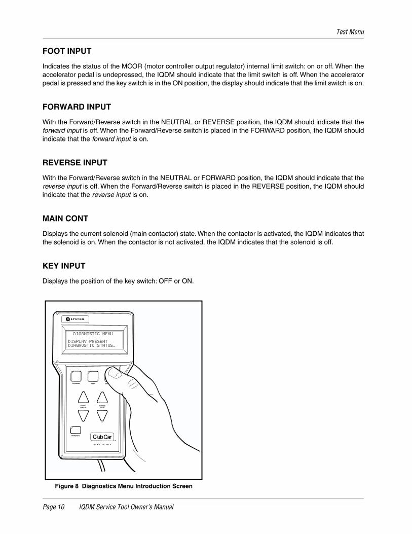
KEY INPUT
Displays the position of the key switch: OFF or ON.
Figure 8 Diagnostics Menu Introduction Screen
PROGRAM
MORE INFO
SCROLLDISPLAY
CHANGEVALUE
TEST DIAGNOSTICS
Diagnostics Menu
IQDM Service Tool Owner’s Manual Page 11
DIAGNOSTICS MENU
The Diagnostics menu is activated by pressing the DIAGNOSTICS button on the IQDM
(Figure 8)
. When theDiagnostics menu is active and there are more than 4
active
faults, the SCROLL DISPLAY buttons can beused to scroll through the faults in the menu.
See following NOTE.
Any fault displayed in the Diagnosticsmenu will aid the trained technician in troubleshooting the vehicle. Faults displayed in the Diagnostics menuoften indicate which components in the electrical system need to be tested and/or replaced.
NOTE:
The MORE INFO button can be pressed to display more information about the selected fault. The item on the
top line
of the display screen is the selected item.
Note that the faults displayed in the Diagnostics menu may not include all of the faults listed in the SpecialDiagnostics menu. This is because the faults displayed in the Diagnostics menu are faults that are currentlyactive. Once a fault has been detected by the speed controller, the code remains in the Diagnostics menu untilthe problem has been corrected. In addition, the fault is stored in the speed controller’s memory for display inthe Special Diagnostics menu.
See Special Diagnostics Menu on page 15.
Since the Diagnostics menu is updated while the vehicle is in operation, the trained technician has the abilityto monitor the occurrence of faults in conditions or locations where a problem with vehicle performance hasbeen reported.
See following Warning.
∆ WARNING
• The vehicle operator should not monitor the IQDM while the vehicle is in motion. A techniciancan monitor the IQDM while traveling as a passenger in the vehicle. Failure to heed thiswarning could result in severe personal injury or death.
CAUSES OF FAULTS
Some common causes of faults are:
• Loose, broken, or disconnected wires or connectors
• Failed components
• Improper adjustment or installation of electrical or mechanical components (examples: brake adjust-ment, improper MCOR installation)
• Improper wiring of electrical components
As shown above, there are many possible causes for faults to occur, and the speed controller has a pro-grammed reaction to each fault that is based on the fault currently detected. The technician should be familiarwith the detected faults and the controller’s reactions to faults to ensure a proper diagnosis.
An example of a possible mis-diagnosis of a vehicle due to a fault: If the three-pin speed sensor wire has beendisconnected, the speed controller will detect a speed sensor fault. When a speed sensor fault is detected, thecontroller responds to the fault by limiting the vehicle speed to 1/2 of its normal top speed. If the technicianreaches the conclusion that the vehicle is running slowly because batteries are heavily discharged, he hasmade an improper diagnosis of the problem.
The vehicle speed controller should be checked for fault codes before any service is performed.
The speed controller, after detecting a fault, will respond in one or more of the following ways:
• A. Reduce vehicle speed to zero by reducing armature current
• B. Reduce vehicle speed to zero by reducing field current to zero
• C. Turn off the solenoid
• D. Cause the vehicle to run at half speed
Diagnostics Menu
Page 12 IQDM Service Tool Owner’s Manual
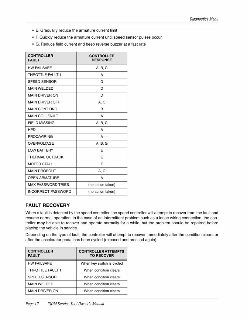
• E. Gradually reduce the armature current limit
• F. Quickly reduce the armature current until speed sensor pulses occur
• G. Reduce field current and beep reverse buzzer at a fast rate
FAULT RECOVERYWhen a fault is detected by the speed controller, the speed controller will attempt to recover from the fault andresume normal operation. In the case of an intermittent problem such as a loose wiring connection, the con-troller may be able to recover and operate normally for a while, but the problem should be repaired beforeplacing the vehicle in service.
Depending on the type of fault, the controller will attempt to recover immediately after the condition clears orafter the accelerator pedal has been cycled (released and pressed again).
CONTROLLERFAULT
CONTROLLERRESPONSE
HW FAILSAFE A, B, C
THROTTLE FAULT 1 A
SPEED SENSOR D
MAIN WELDED D
MAIN DRIVER ON D
MAIN DRIVER OFF A, C
MAIN CONT DNC B
MAIN COIL FAULT A
FIELD MISSING A, B, C
HPD A
PROC/WIRING A
OVERVOLTAGE A, B, G
LOW BATTERY E
THERMAL CUTBACK E
MOTOR STALL F
MAIN DROPOUT A, C
OPEN ARMATURE A
MAX PASSWORD TRIES (no action taken)
INCORRECT PASSWORD (no action taken)
CONTROLLERFAULT
CONTROLLER ATTEMPTS TO RECOVER
HW FAILSAFE When key switch is cycled
THROTTLE FAULT 1 When condition clears
SPEED SENSOR When condition clears
MAIN WELDED When condition clears
MAIN DRIVER ON When condition clears
Diagnostics Menu
IQDM Service Tool Owner’s Manual Page 13
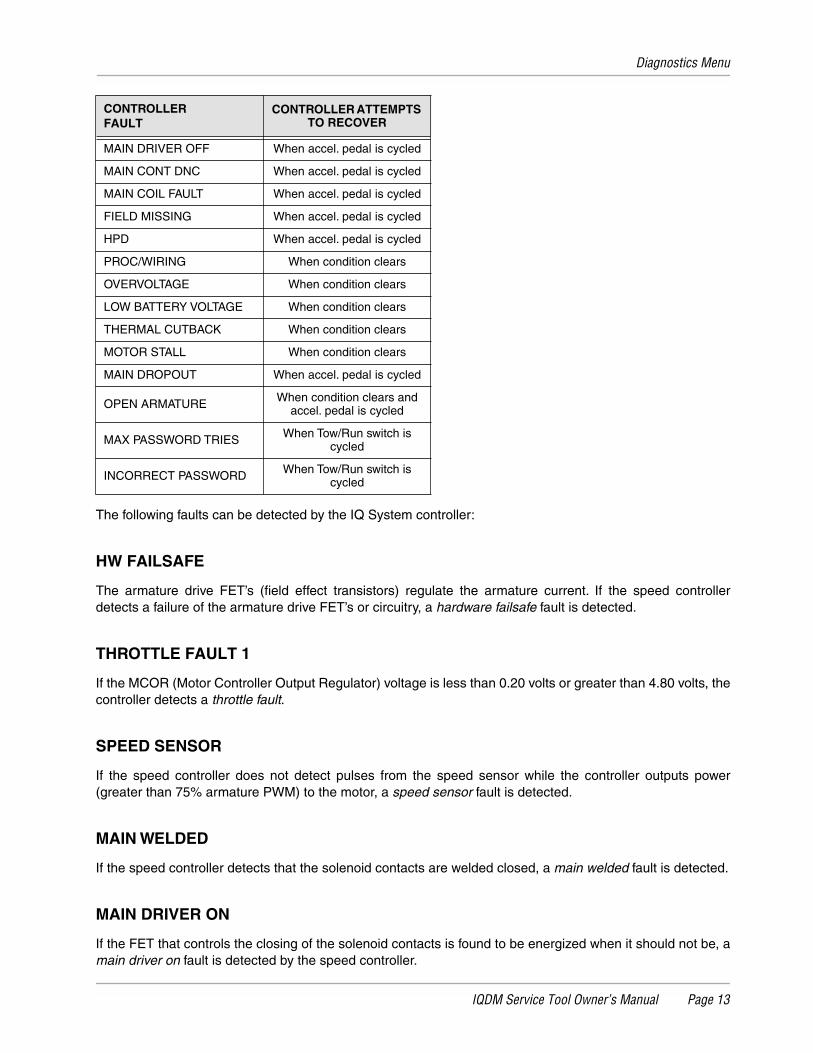
The following faults can be detected by the IQ System controller:
HW FAILSAFE
The armature drive FET’s (field effect transistors) regulate the armature current. If the speed controllerdetects a failure of the armature drive FET’s or circuitry, a hardware failsafe fault is detected.
THROTTLE FAULT 1
If the MCOR (Motor Controller Output Regulator) voltage is less than 0.20 volts or greater than 4.80 volts, thecontroller detects a throttle fault.
SPEED SENSOR
If the speed controller does not detect pulses from the speed sensor while the controller outputs power(greater than 75% armature PWM) to the motor, a speed sensor fault is detected.
MAIN WELDED
If the speed controller detects that the solenoid contacts are welded closed, a main welded fault is detected.
MAIN DRIVER ON
If the FET that controls the closing of the solenoid contacts is found to be energized when it should not be, amain driver on fault is detected by the speed controller.
MAIN DRIVER OFF When accel. pedal is cycled
MAIN CONT DNC When accel. pedal is cycled
MAIN COIL FAULT When accel. pedal is cycled
FIELD MISSING When accel. pedal is cycled
HPD When accel. pedal is cycled
PROC/WIRING When condition clears
OVERVOLTAGE When condition clears
LOW BATTERY VOLTAGE When condition clears
THERMAL CUTBACK When condition clears
MOTOR STALL When condition clears
MAIN DROPOUT When accel. pedal is cycled
OPEN ARMATURE When condition clears and accel. pedal is cycled
MAX PASSWORD TRIES When Tow/Run switch is cycled
INCORRECT PASSWORD When Tow/Run switch is cycled
CONTROLLERFAULT
CONTROLLER ATTEMPTS TO RECOVER
Diagnostics Menu
Page 14 IQDM Service Tool Owner’s Manual
MAIN DRIVER OFF
If the FET that controls the closing of the solenoid is not energized when it should be, a main driver off faultis detected by the speed controller.
MAIN CONT DNC
The main cont dnc (main contactor (solenoid) did not close) fault is detected when the speed controller hassent voltage to the solenoid activating coil but the solenoid contacts are not closed.
MAIN COIL FAULT
If the speed controller determines that the solenoid is not closing as a result of a solenoid coil failure, a maincoil fault is detected.
FIELD MISSING
If the speed controller is operating at a duty cycle of greater than 90% (almost full speed) and the field currentis less than 3 amps, a field missing fault is detected by the speed controller.
HPD
The HPD (High Pedal Detect) fault is detected if the accelerator pedal is already depressed when the keyswitch is turned to the ON position. This fault is also detected if the accelerator pedal is pressed when theselected direction is changed by pressing the Forward/Reverse switch. This fault, when not caused by theoperator, can indicate that the pedal limit switch has failed closed.
PROC/WIRING
This fault is detected if the Forward/Reverse switch is giving a signal to place the controller in forward andreverse at the same time. This rare fault can be caused by a failed switch or improper vehicle wiring.
OVERVOLTAGE
If the speed controller detects that the battery voltage is too high (68.4 to 75.6 volts DC), the overvoltage faultis detected.
LOW BATTERY VOLTAGE
If the battery voltage falls below 34 volts ±5%, the low battery voltage fault is detected by the speed controller.
THERMAL CUTBACK
If the controller heatsink temperature is found to be in excess of 85 °C ±5 °C (185 °F ±41 °F) or below –25 °C±5 °C (–13 °F ±34.3 °F), the thermal cutback fault is detected.
MOTOR STALL
If the motor current is high and there is no movement of the vehicle wheels for a short period of time, a motorstall is detected by the speed controller. This fault can be caused by an operator holding the vehicle on a hillby depressing the accelerator pedal instead of the brake pedal.
Special Diagnostics Menu
IQDM Service Tool Owner’s Manual Page 15
MAIN DROPOUT
If the controller detects that the solenoid contacts have opened while the vehicle is in operation, a main drop-out fault is detected.
OPEN ARMATURE
If the accelerator pedal is pressed 2/3 to the floor, the armature current is less than 20 amps, and there are nospeed sensor pulses, an open armature fault is detected.
INCORRECT PASSWORD
Each vehicle has a password in the form of a unique set of codes used to place the vehicle in "private speedmode". If a set of codes has been entered incorrectly, the incorrect password fault is declared. For additionalinformation on codes, refer to Password Tries. See Password Tries on page 9.
MAX PASSWORD TRIES
The max password tries fault is declared when the incorrect password fault has been declared several times.In the event that the max password tries fault is indicated, the speed controller must be removed and shippedto Club Car before it can ever be placed in "private speed mode". See Password Tries on page 9.
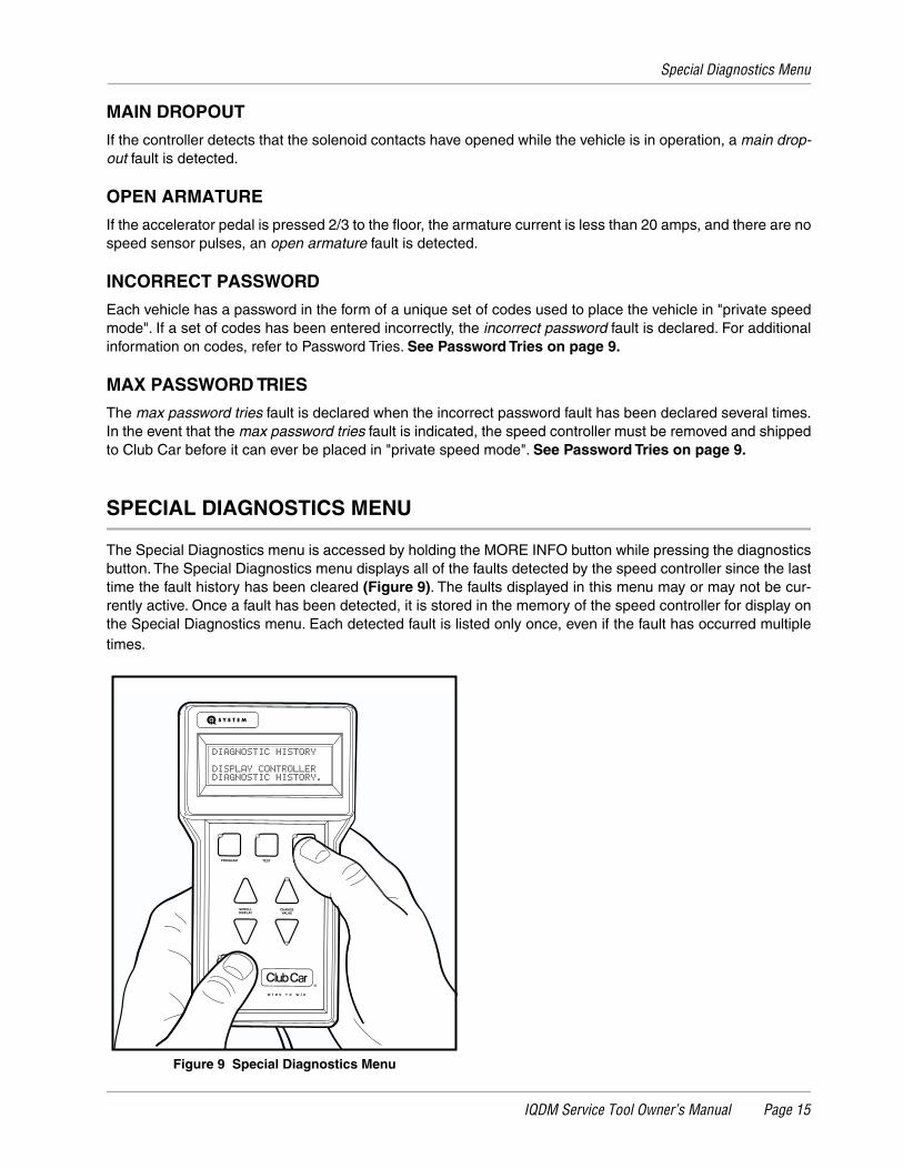
SPECIAL DIAGNOSTICS MENU
The Special Diagnostics menu is accessed by holding the MORE INFO button while pressing the diagnosticsbutton. The Special Diagnostics menu displays all of the faults detected by the speed controller since the lasttime the fault history has been cleared (Figure 9). The faults displayed in this menu may or may not be cur-rently active. Once a fault has been detected, it is stored in the memory of the speed controller for display onthe Special Diagnostics menu. Each detected fault is listed only once, even if the fault has occurred multipletimes.
Figure 9 Special Diagnostics Menu
PROGRAM
MORE INFO
SCROLLDISPLAY
CHANGEVALUE
TEST DIAGNOSTICS
Special Program Menu
Page 16 IQDM Service Tool Owner’s Manual
FAULT HISTORYThe fault history can be useful in determining the cause of a vehicle problem; however, the fault history aloneshould not be the factor that determines when a component is replaced. Some faults detected by the speedcontroller are not the result of a failed component, and are instead the result of operator error. If a faultappears in the fault history, the trained technician should attempt to determine when and where the fault hasoccurred. For example, if the motor stall fault is present in the fault history, the trained technician may be ableto determine the location on the course where an operator has held the vehicle on a hill by using the acceler-ator pedal.
CLEARING FAULT HISTORYAfter a repair has been made, the fault history should be cleared. This will enable the trained technician toproperly troubleshoot the vehicle in the future, in the event that another problem occurs. It is recommendedthat the fault history be cleared in order to avoid the replacement of a component that caused a fault in thepast, but has been replaced and is now functioning correctly. For example, if the MCOR device was discon-nected and the speed controller detected a fault code associated with the throttle, the fault history should becleared so that any future problem is not diagnosed incorrectly as a throttle problem. See Clear Diag Historyon page 20.
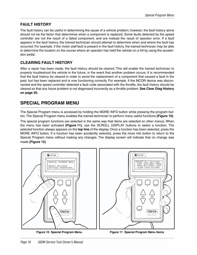
SPECIAL PROGRAM MENU
The Special Program menu is accessed by holding the MORE INFO button while pressing the program but-ton. The Special Program menu enables the trained technician to perform many useful functions (Figure 10).
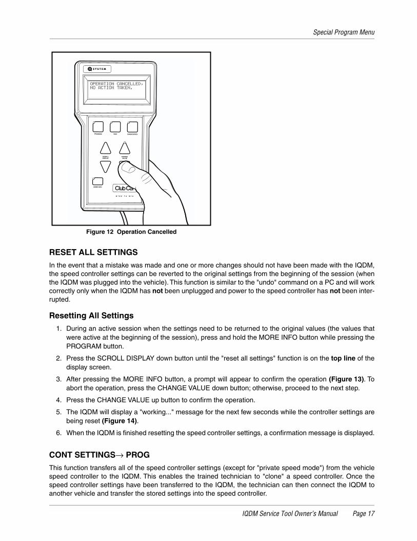
The special program functions are selected in the same way that items are selected on other menus. Whenthe menu has been activated (Figure 11), use the SCROLL DISPLAY buttons to select a function. Theselected function always appears on the top line of the display. Once a function has been selected, press theMORE INFO button. If a function has been accidently selected, press the more info button to return to theSpecial Program menu without making any changes. The display screen will indicate that no change wasmade (Figure 12).
Figure 10 Special Program Menu Figure 11 Special Program Menu Items
PROGRAM
MORE INFO
SCROLLDISPLAY
CHANGEVALUE
TEST DIAGNOSTICS PROGRAM
MORE INFO
SCROLLDISPLAY
CHANGEVALUE
TEST DIAGNOSTICS
Special Program Menu
IQDM Service Tool Owner’s Manual Page 17
RESET ALL SETTINGS
In the event that a mistake was made and one or more changes should not have been made with the IQDM,the speed controller settings can be reverted to the original settings from the beginning of the session (whenthe IQDM was plugged into the vehicle). This function is similar to the "undo" command on a PC and will workcorrectly only when the IQDM has not been unplugged and power to the speed controller has not been inter-rupted.
Resetting All Settings
1. During an active session when the settings need to be returned to the original values (the values thatwere active at the beginning of the session), press and hold the MORE INFO button while pressing thePROGRAM button.
2. Press the SCROLL DISPLAY down button until the "reset all settings" function is on the top line of thedisplay screen.
3. After pressing the MORE INFO button, a prompt will appear to confirm the operation (Figure 13). Toabort the operation, press the CHANGE VALUE down button; otherwise, proceed to the next step.
4. Press the CHANGE VALUE up button to confirm the operation.
5. The IQDM will display a "working..." message for the next few seconds while the controller settings arebeing reset (Figure 14).
6. When the IQDM is finished resetting the speed controller settings, a confirmation message is displayed.
CONT SETTINGS→ PROG
This function transfers all of the speed controller settings (except for "private speed mode") from the vehiclespeed controller to the IQDM. This enables the trained technician to "clone" a speed controller. Once thespeed controller settings have been transferred to the IQDM, the technician can then connect the IQDM toanother vehicle and transfer the stored settings into the speed controller.
Figure 12 Operation Cancelled
PROGRAM
MORE INFO
SCROLLDISPLAY
CHANGEVALUE
TEST DIAGNOSTICS
Special Program Menu
Page 18 IQDM Service Tool Owner’s Manual
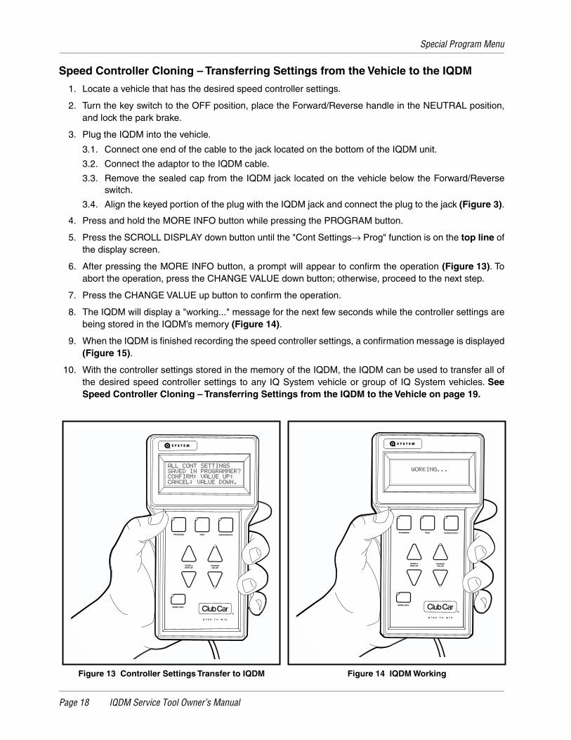
Speed Controller Cloning – Transferring Settings from the Vehicle to the IQDM
1. Locate a vehicle that has the desired speed controller settings.
2. Turn the key switch to the OFF position, place the Forward/Reverse handle in the NEUTRAL position,and lock the park brake.
3. Plug the IQDM into the vehicle.
3.1. Connect one end of the cable to the jack located on the bottom of the IQDM unit.
3.2. Connect the adaptor to the IQDM cable.
3.3. Remove the sealed cap from the IQDM jack located on the vehicle below the Forward/Reverseswitch.
3.4. Align the keyed portion of the plug with the IQDM jack and connect the plug to the jack (Figure 3).
4. Press and hold the MORE INFO button while pressing the PROGRAM button.
5. Press the SCROLL DISPLAY down button until the "Cont Settings→ Prog" function is on the top line ofthe display screen.
6. After pressing the MORE INFO button, a prompt will appear to confirm the operation (Figure 13). Toabort the operation, press the CHANGE VALUE down button; otherwise, proceed to the next step.
7. Press the CHANGE VALUE up button to confirm the operation.
8. The IQDM will display a "working..." message for the next few seconds while the controller settings arebeing stored in the IQDM’s memory (Figure 14).
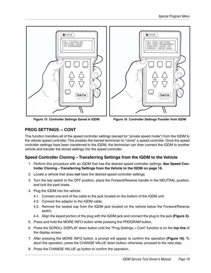
9. When the IQDM is finished recording the speed controller settings, a confirmation message is displayed(Figure 15).
10. With the controller settings stored in the memory of the IQDM, the IQDM can be used to transfer all ofthe desired speed controller settings to any IQ System vehicle or group of IQ System vehicles. SeeSpeed Controller Cloning – Transferring Settings from the IQDM to the Vehicle on page 19.
Figure 13 Controller Settings Transfer to IQDM Figure 14 IQDM Working
PROGRAM
MORE INFO
SCROLLDISPLAY
CHANGEVALUE
TEST DIAGNOSTICSPROGRAM
MORE INFO
SCROLLDISPLAY
CHANGEVALUE
TEST DIAGNOSTICS
Special Program Menu
IQDM Service Tool Owner’s Manual Page 19
PROG SETTINGS→ CONT
This function transfers all of the speed controller settings (except for "private speed mode") from the IQDM tothe vehicle speed controller. This enables the trained technician to "clone" a speed controller. Once the speedcontroller settings have been transferred to the IQDM, the technician can then connect the IQDM to anothervehicle and transfer the stored settings into the speed controller.
Speed Controller Cloning – Transferring Settings from the IQDM to the Vehicle
1. Perform this procedure with an IQDM that has the desired speed controller settings. See Speed Con-troller Cloning – Transferring Settings from the Vehicle to the IQDM on page 18.
2. Locate a vehicle that does not have the desired speed controller settings.
3. Turn the key switch to the OFF position, place the Forward/Reverse handle in the NEUTRAL position,and lock the park brake.
4. Plug the IQDM into the vehicle.
4.1. Connect one end of the cable to the jack located on the bottom of the IQDM unit.
4.2. Connect the adaptor to the IQDM cable.
4.3. Remove the sealed cap from the IQDM jack located on the vehicle below the Forward/Reverseswitch.
4.4. Align the keyed portion of the plug with the IQDM jack and connect the plug to the jack (Figure 3).
5. Press and hold the MORE INFO button while pressing the PROGRAM button.
6. Press the SCROLL DISPLAY down button until the "Prog Settings→ Cont" function is on the top line ofthe display screen.
7. After pressing the MORE INFO button, a prompt will appear to confirm the operation (Figure 16). Toabort the operation, press the CHANGE VALUE down button; otherwise, proceed to the next step.
8. Press the CHANGE VALUE up button to confirm the operation.
Figure 15 Controller Settings Saved in IQDM Figure 16 Controller Settings Transfer from IQDM
PROGRAM
MORE INFO
SCROLLDISPLAY
CHANGEVALUE
TEST DIAGNOSTICS PROGRAM
MORE INFO
SCROLLDISPLAY
CHANGEVALUE
TEST DIAGNOSTICS
Special Program Menu
Page 20 IQDM Service Tool Owner’s Manual
9. The IQDM will display a "working..." message for the next few seconds while the controller settings aretransferred the IQDM’s memory to the speed controller (Figure 14).
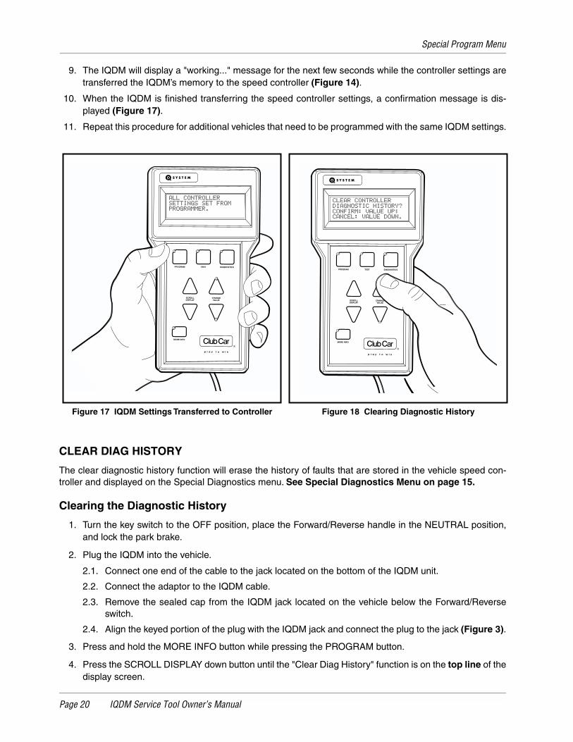
10. When the IQDM is finished transferring the speed controller settings, a confirmation message is dis-played (Figure 17).
11. Repeat this procedure for additional vehicles that need to be programmed with the same IQDM settings.
CLEAR DIAG HISTORY
The clear diagnostic history function will erase the history of faults that are stored in the vehicle speed con-troller and displayed on the Special Diagnostics menu. See Special Diagnostics Menu on page 15.
Clearing the Diagnostic History
1. Turn the key switch to the OFF position, place the Forward/Reverse handle in the NEUTRAL position,and lock the park brake.
2. Plug the IQDM into the vehicle.
2.1. Connect one end of the cable to the jack located on the bottom of the IQDM unit.
2.2. Connect the adaptor to the IQDM cable.
2.3. Remove the sealed cap from the IQDM jack located on the vehicle below the Forward/Reverseswitch.
2.4. Align the keyed portion of the plug with the IQDM jack and connect the plug to the jack (Figure 3).
3. Press and hold the MORE INFO button while pressing the PROGRAM button.
4. Press the SCROLL DISPLAY down button until the "Clear Diag History" function is on the top line of thedisplay screen.
Figure 17 IQDM Settings Transferred to Controller Figure 18 Clearing Diagnostic History
PROGRAM
MORE INFO
SCROLLDISPLAY
CHANGEVALUE
TEST DIAGNOSTICSPROGRAM
MORE INFO
SCROLLDISPLAY
CHANGEVALUE
TEST DIAGNOSTICS
Special Program Menu
IQDM Service Tool Owner’s Manual Page 21
5. After pressing the MORE INFO button, a prompt will appear to confirm the operation (Figure 18). Toabort the operation, press the CHANGE VALUE down button; otherwise, proceed to the next step.
6. Press the CHANGE VALUE up button to confirm the operation.
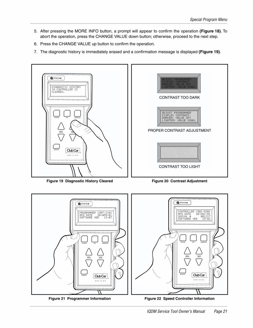
7. The diagnostic history is immediately erased and a confirmation message is displayed (Figure 19).
Figure 19 Diagnostic History Cleared Figure 20 Contrast Adjustment
Figure 21 Programmer Information Figure 22 Speed Controller Information
PROGRAM
MORE INFO
SCROLLDISPLAY
CHANGEVALUE
TEST DIAGNOSTICS
PROPER CONTRAST ADJUSTMENT
CONTRAST TOO DARK
CONTRAST TOO LIGHT
PROGRAM
MORE INFO
SCROLLDISPLAY
CHANGEVALUE
TEST DIAGNOSTICSPROGRAM
MORE INFO
SCROLLDISPLAY
CHANGEVALUE
TEST DIAGNOSTICS
IQDM Troubleshooting
Page 22 IQDM Service Tool Owner’s Manual
CONTRAST ADJUSTMENT
It may occasionally be necessary to adjust the contrast of the display screen. After selecting the contrastadjustment item from the Special Program menu, use the CHANGE VALUE buttons to adjust the contrast forthe best readability (Figure 20).
LANGUAGE SELECTION
English is the only language supported by the IQDM. There are two selectable options, "English", and"numeric". The numeric option should never be selected, as this will change the Test menu items from Englishwords to numeric values. These numeric values are useful for the OEM only, and will be of no use to thetrained technician.
PROGRAMMER INFO
This menu selection displays information pertaining to the IQDM. The information provided from this menuselection includes programmer model number, the date the IQDM was manufactured, and the IQDM softwareversion (Figure 21).
CONTROLLER INFO
This menu selection displays information pertaining to the speed controller. The information provided from thismenu selection includes the speed controller model number, the date the speed controller was manufactured,the speed controller serial number, and the speed controller software version (Figure 22).
IQDM TROUBLESHOOTING
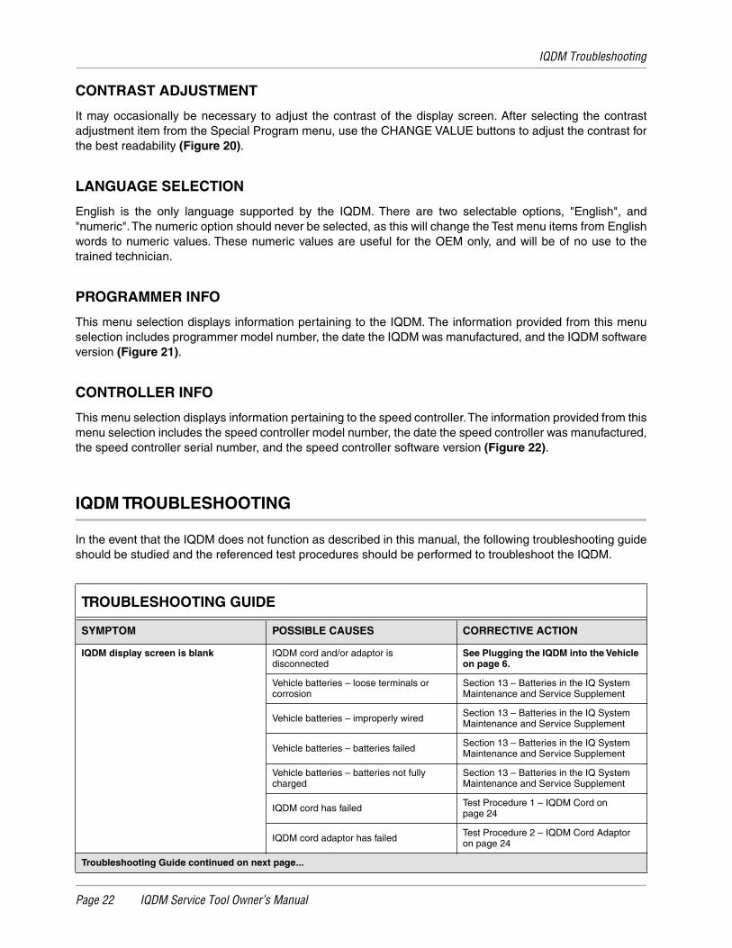
In the event that the IQDM does not function as described in this manual, the following troubleshooting guideshould be studied and the referenced test procedures should be performed to troubleshoot the IQDM.
TROUBLESHOOTING GUIDE
SYMPTOM POSSIBLE CAUSES CORRECTIVE ACTION
IQDM display screen is blank IQDM cord and/or adaptor is disconnected
See Plugging the IQDM into the Vehicle on page 6.
Vehicle batteries – loose terminals or corrosion
Section 13 – Batteries in the IQ System Maintenance and Service Supplement
Vehicle batteries – improperly wired Section 13 – Batteries in the IQ System Maintenance and Service Supplement
Vehicle batteries – batteries failed Section 13 – Batteries in the IQ System Maintenance and Service Supplement
Vehicle batteries – batteries not fully charged
Section 13 – Batteries in the IQ System Maintenance and Service Supplement
IQDM cord has failed Test Procedure 1 – IQDM Cord on page 24
IQDM cord adaptor has failed Test Procedure 2 – IQDM Cord Adaptor on page 24
Troubleshooting Guide continued on next page...
IQDM Troubleshooting
IQDM Service Tool Owner’s Manual Page 23
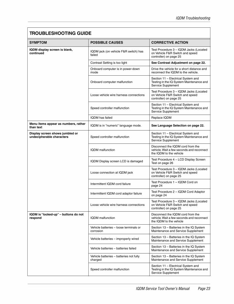
IQDM display screen is blank, continued IQDM jack (on vehicle F&R switch) has
failed
Test Procedure 3 – IQDM Jacks (Located on Vehicle F&R Switch and speed controller) on page 25
Contrast Setting is too light See Contrast Adjustment on page 22.
Onboard computer is in power-down mode
Drive the vehicle for a short distance and reconnect the IQDM to the vehicle.
Onboard computer malfunctionSection 11 – Electrical System and Testing in the IQ System Maintenance and Service Supplement
Loose vehicle wire harness connectionsTest Procedure 3 – IQDM Jacks (Located on Vehicle F&R Switch and speed controller) on page 25
Speed controller malfunctionSection 11 – Electrical System and Testing in the IQ System Maintenance and Service Supplement
IQDM has failed Replace IQDM
Menu items appear as numbers, rather than text IQDM is in "numeric" language mode. See Language Selection on page 22.
Display screen shows jumbled or undecipherable characters Speed controller malfunction
Section 11 – Electrical System and Testing in the IQ System Maintenance and Service Supplement
IQDM malfunctionDisconnect the IQDM cord from the vehicle. Wait a few seconds and reconnect the IQDM to the vehicle
IQDM Display screen LCD is damaged Test Procedure 4 – LCD Display Screen Test on page 26
Loose connection at IQDM jackTest Procedure 3 – IQDM Jacks (Located on Vehicle F&R Switch and speed controller) on page 25
Intermittent IQDM cord failure Test Procedure 1 – IQDM Cord on page 24
Intermittent IQDM cord adaptor failure Test Procedure 2 – IQDM Cord Adaptor on page 24
Loose vehicle wire harness connectionsTest Procedure 3 – IQDM Jacks (Located on Vehicle F&R Switch and speed controller) on page 25
IQDM is “locked-up” – buttons do not respond IQDM malfunction
Disconnect the IQDM cord from the vehicle. Wait a few seconds and reconnect the IQDM to the vehicle
Vehicle batteries – loose terminals or corrosion
Section 13 – Batteries in the IQ System Maintenance and Service Supplement
Vehicle batteries – improperly wired Section 13 – Batteries in the IQ System Maintenance and Service Supplement
Vehicle batteries – batteries failed Section 13 – Batteries in the IQ System Maintenance and Service Supplement
Vehicle batteries – batteries not fully charged
Section 13 – Batteries in the IQ System Maintenance and Service Supplement
Speed controller malfunctionSection 11 – Electrical System and Testing in the IQ System Maintenance and Service Supplement
TROUBLESHOOTING GUIDE
SYMPTOM POSSIBLE CAUSES CORRECTIVE ACTION
Test Procedures
Page 24 IQDM Service Tool Owner’s Manual
TEST PROCEDURES
The following test procedures enable the technician to test the IQDM handset and the components of the IQSystem vehicle that are related to the proper operation of the IQDM. This owner’s manual does not containdetailed information for troubleshooting the vehicle. Refer to the vehicle maintenance and service manual fordetailed vehicle troubleshooting and service procedures.
∆ WARNING
• If wires are removed or replaced make sure wiring and wire harness are properly routed andsecured. Failure to properly route and secure wiring could result in vehicle malfunction,property damage or personal injury.
INDEX OF TEST PROCEDURES
1. IQDM Cord
2. IQDM Cord Adaptor
3. IQDM Jacks (Located on Vehicle F&R Switch and speed controller)
4. LCD Display Screen Test
TEST PROCEDURE 1 – IQDM CORD
Read DANGER, WARNING, and CAUTION on page 3.
1. Using a multimeter set for 200 Ω (ohms), place the red (+) probe into one of the terminals on the end ofthe cord with the square plug.
2. Place the black (–) probe on each of the pins, one at a time, on the other plug of the plug.
3. The multimeter should indicate continuity on only one pin. If any other reading is obtained, the cord mustbe replaced.
4. Repeat the procedure three more times, each time with the red (+) probe inserted into a different terminalon the end of the cord with the square plug.
TEST PROCEDURE 2 – IQDM CORD ADAPTOR
Read DANGER, WARNING, and CAUTION on page 3.
The procedure for testing the IQDM cord adaptor is similar to the cord test.
1. Using a multimeter set for 200 Ω (ohms), place the red (+) probe into one of the terminals on the end ofthe adapter with the square plug.
2. Place the black (–) probe on each of the pins, one at a time, on the other plug of the adaptor.
3. The multimeter should indicate continuity on only one pin. If any other reading is obtained, the adaptormust be replaced.
4. Repeat the procedure three more times, each time with the red (+) probe inserted into a different terminalon the end of the adaptor with the square plug.
Test Procedures
IQDM Service Tool Owner’s Manual Page 25
TEST PROCEDURE 3 – IQDM JACKS (LOCATED ON VEHICLE F&R SWITCH AND SPEED CONTROLLER)
Read DANGER, WARNING, and CAUTION on page 3.
1. Turn the key switch to the OFF position, place the Forward/Reverse handle in the NEUTRAL position,and lock the park brake.
2. Place the Tow/Run switch in the TOW position, disconnect the batteries, negative (–) cable first, and wait90 seconds for the speed controller capacitors to discharge. See WARNING on page 3.
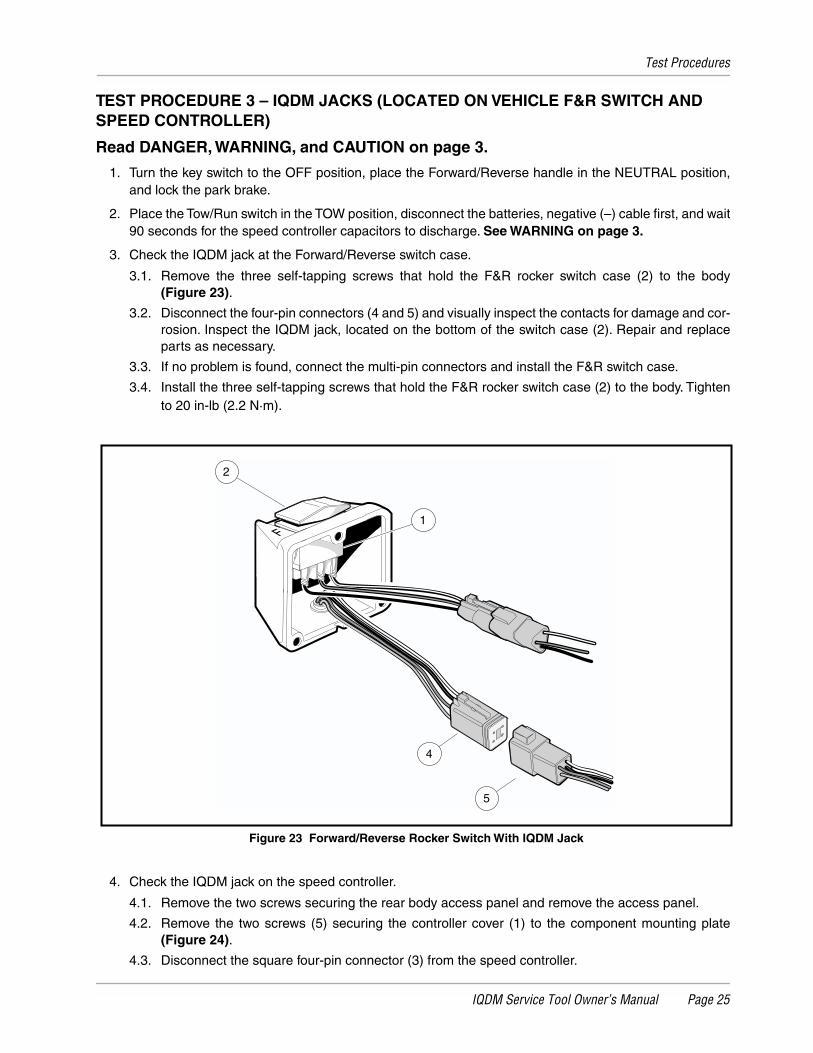
3. Check the IQDM jack at the Forward/Reverse switch case.
3.1. Remove the three self-tapping screws that hold the F&R rocker switch case (2) to the body(Figure 23).
3.2. Disconnect the four-pin connectors (4 and 5) and visually inspect the contacts for damage and cor-rosion. Inspect the IQDM jack, located on the bottom of the switch case (2). Repair and replaceparts as necessary.
3.3. If no problem is found, connect the multi-pin connectors and install the F&R switch case.
3.4. Install the three self-tapping screws that hold the F&R rocker switch case (2) to the body. Tightento 20 in-lb (2.2 N·m).
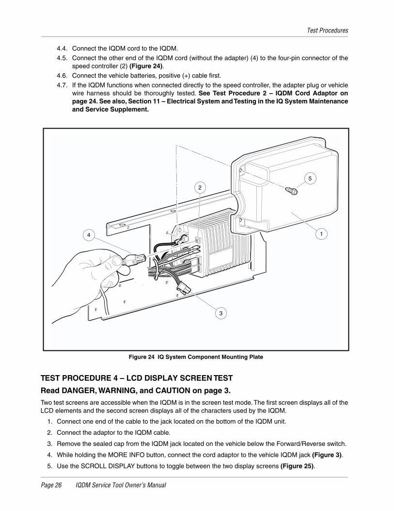
4. Check the IQDM jack on the speed controller.
4.1. Remove the two screws securing the rear body access panel and remove the access panel.
4.2. Remove the two screws (5) securing the controller cover (1) to the component mounting plate(Figure 24).
4.3. Disconnect the square four-pin connector (3) from the speed controller.
Figure 23 Forward/Reverse Rocker Switch With IQDM Jack
FF
2
1
4
5
Test Procedures
Page 26 IQDM Service Tool Owner’s Manual
4.4. Connect the IQDM cord to the IQDM.
4.5. Connect the other end of the IQDM cord (without the adapter) (4) to the four-pin connector of thespeed controller (2) (Figure 24).
4.6. Connect the vehicle batteries, positive (+) cable first.
4.7. If the IQDM functions when connected directly to the speed controller, the adapter plug or vehiclewire harness should be thoroughly tested. See Test Procedure 2 – IQDM Cord Adaptor onpage 24. See also, Section 11 – Electrical System and Testing in the IQ System Maintenanceand Service Supplement.
TEST PROCEDURE 4 – LCD DISPLAY SCREEN TEST
Read DANGER, WARNING, and CAUTION on page 3.
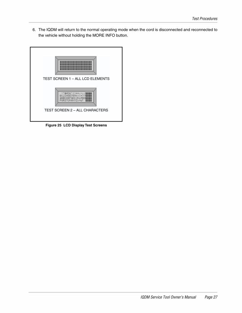
Two test screens are accessible when the IQDM is in the screen test mode. The first screen displays all of theLCD elements and the second screen displays all of the characters used by the IQDM.
1. Connect one end of the cable to the jack located on the bottom of the IQDM unit.
2. Connect the adaptor to the IQDM cable.
3. Remove the sealed cap from the IQDM jack located on the vehicle below the Forward/Reverse switch.
4. While holding the MORE INFO button, connect the cord adaptor to the vehicle IQDM jack (Figure 3).
5. Use the SCROLL DISPLAY buttons to toggle between the two display screens (Figure 25).
Figure 24 IQ System Component Mounting Plate
4
2
3
1
5
Test Procedures
IQDM Service Tool Owner’s Manual Page 27
6. The IQDM will return to the normal operating mode when the cord is disconnected and reconnected tothe vehicle without holding the MORE INFO button.
Figure 25 LCD Display Test Screens
TEST SCREEN 2 – ALL CHARACTERS
TEST SCREEN 1 – ALL LCD ELEMENTS

Recommended