Alessandro Fabris 39th International Nathiagali Summer College, 4th-9th August 2014
RF POWER GENERATION AND TRANSMISSION FOR PARTICLE
ACCELERATORS
Alessandro Fabris Elettra-Sincrotrone Trieste S.C.p.A, Italy
39th International Nathiagali Summer College
4th – 9th August 2014
2

Alessandro Fabris 39th International Nathiagali Summer College, 4th-9th August 2014
OVERVIEW
Introduction
Power generation
Tubes
Solid state
Power transmission
Coaxial
Waveguide
Summary
References
3

Alessandro Fabris 39th International Nathiagali Summer College, 4th-9th August 2014
INTRODUCTION
4

Alessandro Fabris 39th International Nathiagali Summer College, 4th-9th August 2014
INTRODUCTION
5
High power RF is needed for particle accelerators
Typical frequency ranges span from tens of MHz to tens of GHz or higher.
Power requirements vary from few kW to few MW in cw (continuous wave) mode operation and to up to 150 MW for pulsed sources.
A power amplifier is the equipment which transforms d.c. electrical input power to RF power amplifying the driving signal provided by the low level RF electronics.
The power transmission system is the assembly of components that performs the tasks to transport the RF power from the RF power source to the cavities.

Alessandro Fabris 39th International Nathiagali Summer College, 4th-9th August 2014
BASIC CONCEPTS
6
Continuous wave (CW) RF System. CW means that RF is uninterrupted. In this context amplitude modulated (AM),
frequency modulated (FM) and phase modulated (PM) RF are considered cw since RF is continuously present.
Pulsed RF system The RF is produced in bursts (pulse) with no RF
present between the bursts. Duty cycle (d.c.)
Measure of the fraction of the time the RF is produced.
If τ is the pulse width and T is the period of the repetition of the pulses, the duty cycle is: d.c. (%) = τ/T *100 For a cw system the d.c. = 100 %.
The duty cycle is also the ratio between average and peak RF power.

Alessandro Fabris 39th International Nathiagali Summer College, 4th-9th August 2014
BASIC CONCEPTS
7
Gain For an amplifier, it is the ratio between output and input power Gain= Prf-out/Pin-out Usually it is measured in dB Gain(dB)=10 Log10(Prf-out/Pin-out)
Efficiency
For an amplifier, it is the ratio between the RF output power and the DC input power
η= Prf-out/Pdc Usually it is measured in %
Attenuation (α)
For a coaxial line or a waveguide represents the loss in the transmission system
Usually it is measured in dB per unit length α(dB)=(10 Log10(Prf-out/Pin-out))/L
Alessandro Fabris 39th International Nathiagali Summer College, 4th-9th August 2014
BASIC CONCEPTS
8
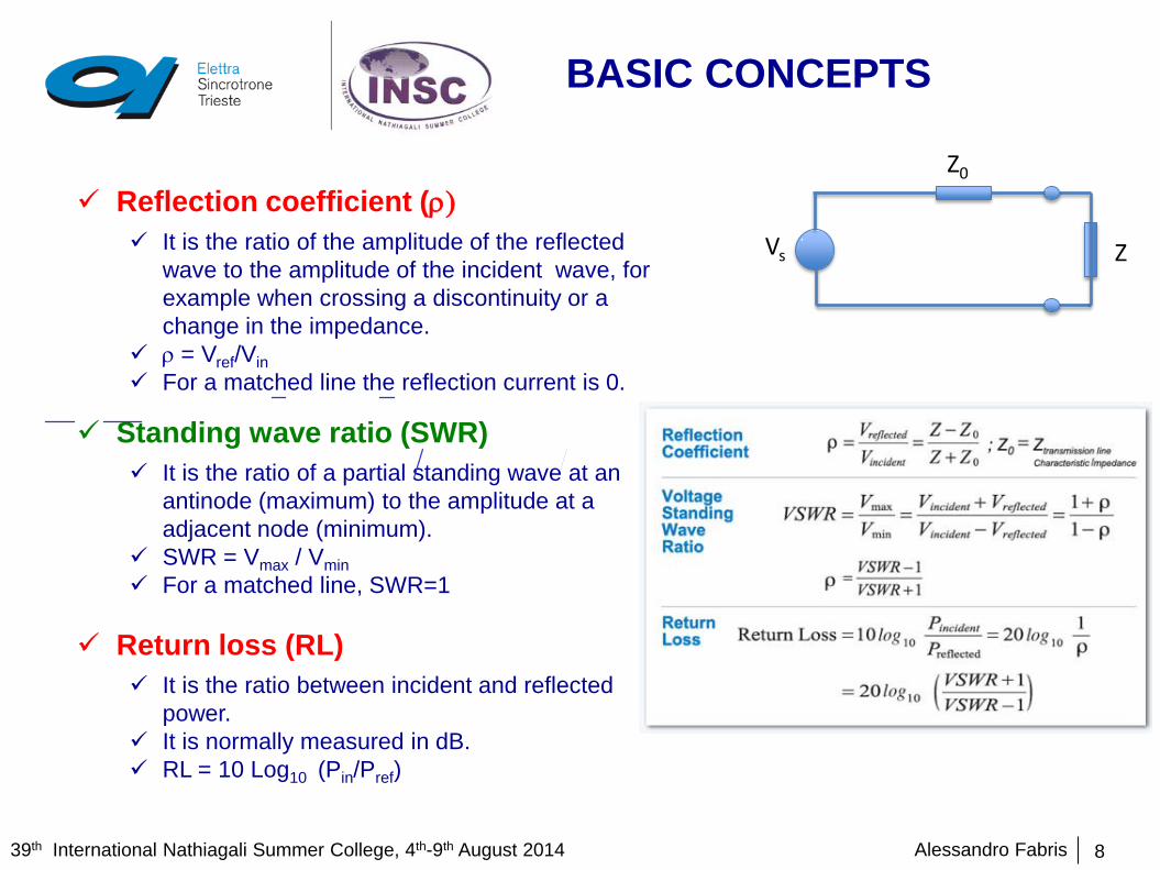
Reflection coefficient (ρ) It is the ratio of the amplitude of the reflected
wave to the amplitude of the incident wave, for example when crossing a discontinuity or a change in the impedance.
ρ = Vref/Vin For a matched line the reflection current is 0.
Standing wave ratio (SWR) It is the ratio of a partial standing wave at an
antinode (maximum) to the amplitude at a adjacent node (minimum).
SWR = Vmax / Vmin For a matched line, SWR=1
Return loss (RL)
It is the ratio between incident and reflected power.
It is normally measured in dB. RL = 10 Log10 (Pin/Pref)
Z0
Vs Z
Alessandro Fabris 39th International Nathiagali Summer College, 4th-9th August 2014
POWER GENERATION
9

Alessandro Fabris 39th International Nathiagali Summer College, 4th-9th August 2014
GENERAL
10
A power amplifier is the equipment which transforms d.c. electrical input power to RF power amplifying the driving signal provided by the low level RF electronics.
If needed, power amplifier can be combined to achieve higher power level. The high power sources represent one of the main capital costs both in
construction and in operations. Technologies
Vacuum tubes Tetrodes Klystron IOT Magnetron Travelling tubes Gyratrons
Solid state

Alessandro Fabris 39th International Nathiagali Summer College, 4th-9th August 2014
CHOICE
11
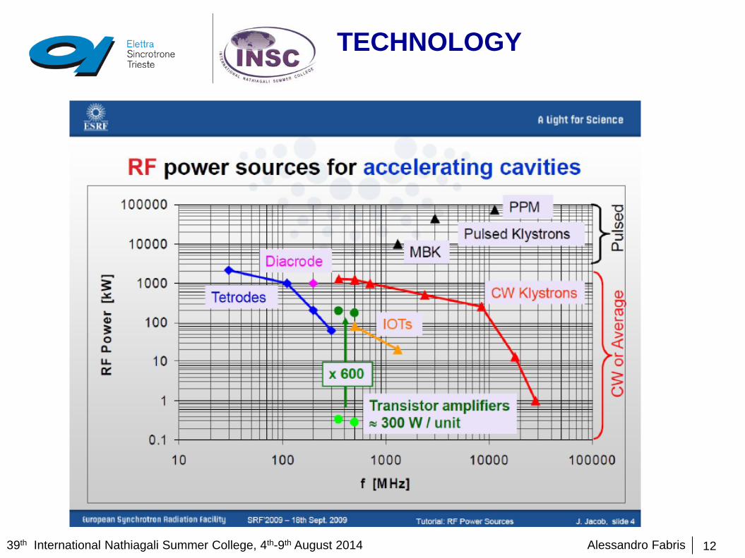
The choice of the technology depends on several considerations:
Frequency
Power level required
Efficiency
Gain
Installation costs
Running costs
Maintenance costs
Size
Weight
Alessandro Fabris 39th International Nathiagali Summer College, 4th-9th August 2014
TECHNOLOGY
12

Alessandro Fabris 39th International Nathiagali Summer College, 4th-9th August 2014
TETRODE - PRINCIPLE
13
THE TETRODE IS A FOUR ELEMENT TUBE. Cathode
Emitting surface Heated by the filament (thermionic emission) Direct or indirect heating. For high power tubes direct heating is
normally used. The most common type is the thoriated tungsten filament
Plate When positive voltage is applied, electrons emitted from the cathode flow to the
plate through the two girds Control grid
Varying voltage, applied to the control grid, controls the current to the plate. Screen grid
Isolates control grid with respect to the plate, reducing parasitic capacitance. Normally it is connected to a positive DC voltage.
THE BEAM IN A TETRODE IS DENSITY MODULATED.

Alessandro Fabris 39th International Nathiagali Summer College, 4th-9th August 2014
TETRODE
14
The construction of a high power tetrode is coaxial with the cathode inside and the anode outside.
This arrangement allows cooling of the cathode. Output power is limited by the maximum current
density available from the cathode and the maximum power density that can be dissipated on the plate.
Transit time between cathode and anode should be much less than the RF period, so spacing between the electrodes must be small enough. This limits the frequency range of operation.

Alessandro Fabris 39th International Nathiagali Summer College, 4th-9th August 2014
TETRODE -SUMMARY
15
FREQUENCY RANGE tens to 500 MHz BANDWIDTH few % MAXIMUM POWER EXAMPLES CW 1 MW up to 30 MHz
200 KW @ 350 MHz pulsed up to 4 MW @ 200 MHz
CLASS OF OPERATION A, AB, B, C EFFICIENCY UP TO 70 % GAIN High gain at low frequencies
Low gain at high frequencies Typical values between 14 and 20 dB
RELIABILITY Medium Cathode lifetime limited to 5000-40000 hours
FEATURES Simplicity Relatively robust Low cost High voltage Low current Transit time limited

Alessandro Fabris 39th International Nathiagali Summer College, 4th-9th August 2014
TETRODES-EXAMPLES
16
10
100
1000
10000
0 100 200 300 400 500
Pow
er k
W p
er s
ingl
e tu
be
Frequency MHz
Tetrodes & Diacrodes available from industry
peak < 1 ms
CW
Eric Montesinos, TIARA Workshop, 2013
Alessandro Fabris 39th International Nathiagali Summer College, 4th-9th August 2014
TETRODES-EXAMPLES
17
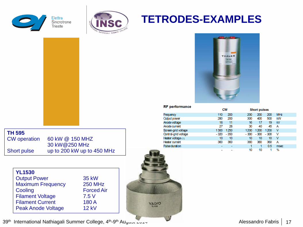
TH 595 CW operation 60 kW @ 150 MHZ 30 kW@250 MHz Short pulse up to 200 kW up to 450 MHz
YL1530 Output Power 35 kW Maximum Frequency 250 MHz Cooling Forced Air Filament Voltage 7.5 V Filament Current 180 A Peak Anode Voltage 12 kV

Alessandro Fabris 39th International Nathiagali Summer College, 4th-9th August 2014
TETRODES AMPLIFIERS EXAMPLES
18
SPS (CERN) Philips 4x550kW 72 tetrode amplifiers
YL1530 Key Attributes Value Output Power 35 kW Maximum Frequency 250 MHz Cooling Forced Air Filament Voltage 7.5 V Filament Current 180 A Peak Anode Voltage 12 kV
Alessandro Fabris 39th International Nathiagali Summer College, 4th-9th August 2014
KLYSTRON - PRINCIPLE
19
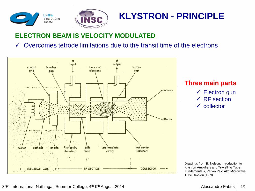
ELECTRON BEAM IS VELOCITY MODULATED Overcomes tetrode limitations due to the transit time of the electrons
Three main parts
Electron gun RF section collector
Drawings from B. Nelson, Introduction to Klystron Amplifiers and Travelling Tube Fundamentals, Varian Palo Alto Microwave Tube Division ,1978
Drawings from B. Nelson, Introduction to Klystron Amplifiers and Travelling Tube Fundamentals, Varian Palo Alto Microwave Tube Division ,1978

Alessandro Fabris 39th International Nathiagali Summer College, 4th-9th August 2014
KLYSTRON - PRINCIPLE
20
Electron Gun
Heater Cathode Control grid (sometimes) Anode
Electrons emitted by the cathode are accelerated to the anode by the positive voltage applied.
A grid may be used to control the flow of electrons to the anode region. This may be also used to switch off the beam completely in some pulsed applications.
Collector Collects the electrons, that from the anode have passed through the RF sections. The collector is not connected to the RF circuitry at all.

Alessandro Fabris 39th International Nathiagali Summer College, 4th-9th August 2014
KLYSTRON - PRINCIPLE
21
RF SECTION Composed of cavities separated by
drift tubes. Cavities are tuned according to the
required operating frequency and bandwidth.
Input RF signal is applied to the first cavity (the buncher) where it excites an electromagnetic RF field.
The RF field in the buncher modulates the velocity of the electron beam. In the drift tube region the electrons are bunched. The bunched electron beam arrives at the output cavity (the catcher) where it
induces an alternating field at the RF frequency as they pass through the catcher gap.
The RF fields can be coupled from the cavity to the output line.

Alessandro Fabris 39th International Nathiagali Summer College, 4th-9th August 2014
KLYSTRON - PRINCIPLE
22
If the process is working properly, the oscillating currents in the catcher cavity will be considerably higher than in the buncher cavity, i.e. amplification has taken place.
Electron beam delivers energy to the cavity, therefore the beam arrives to the collector with less energy than it had when crossing the input cavity. The difference is roughly the RF power delivered.
Intermediate cavities improve the bunching process, i.e.: Increase amplifier gain and efficiency. Increase bandwdith
Effect is similar to adding more stages to an amplifier
To keep the electron beam formed properly, an axial magnetic field is used to confine it. Magnet coils are used.

Alessandro Fabris 39th International Nathiagali Summer College, 4th-9th August 2014
KLYSTRON - SUMMARY
23
NOTE: Multi beam klystrons may represent an option to deliver higher power with high efficiency not increasing the high voltage
FREQUENCY RANGE 300 MHz to 30 GHz BANDWIDTH few % MAXIMUM POWER EXAMPLES Few MW in cw
Up to 100 MW in pulsed operation CLASS OF OPERATION A EFFICIENCY 40 to 60 % GAIN High gain
Typical values around 40 dB RELIABILITY Medium
Cathode lifetime limited FEATURES High power
High gain Controlled output High voltage Efficiency Needs expert care

Alessandro Fabris 39th International Nathiagali Summer College, 4th-9th August 2014
KLYSTRON - EXAMPLES
24
External cavities UHF Klystron used at Elettra 60 kW cw 500 MHz (E2v 2672BCD)) 300 kW cw 500 MHz klystron (Thales
TH22161)
Note: Dimensions not equivalent

Alessandro Fabris 39th International Nathiagali Summer College, 4th-9th August 2014
KLYSTRON - EXAMPLES
25
45 MW pulsed S-band klystron (Thales TH2132A)
50 MW pulsed X-band klystron (SLAC XL5)

Alessandro Fabris 39th International Nathiagali Summer College, 4th-9th August 2014
KLYSTRON PFN MODULATOR
26

Alessandro Fabris 39th International Nathiagali Summer College, 4th-9th August 2014
KLYSTRON BASED POWER PLANTS - EXAMPLES
27
45 MW peak S-band klystron and modulator at FERMI
60 kW cw 500MHz at Elettra
Alessandro Fabris 39th International Nathiagali Summer College, 4th-9th August 2014
IOT
28
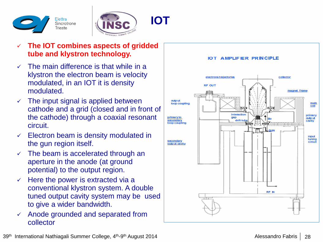
The IOT combines aspects of gridded tube and klystron technology.
The main difference is that while in a klystron the electron beam is velocity modulated, in an IOT it is density modulated.
The input signal is applied between cathode and a grid (closed and in front of the cathode) through a coaxial resonant circuit.
Electron beam is density modulated in the gun region itself.
The beam is accelerated through an aperture in the anode (at ground potential) to the output region.
Here the power is extracted via a conventional klystron system. A double tuned output cavity system may be used to give a wider bandwidth.
Anode grounded and separated from collector

Alessandro Fabris 39th International Nathiagali Summer College, 4th-9th August 2014
IOT -SUMMARY
29
FREQUENCY RANGE 100 MHz to 2 GHz BANDWIDTH few % MAXIMUM POWER EXAMPLES 100 KW CLASS OF OPERATION B, C EFFICIENCY Up to 80 % GAIN Medium gain (around 23 dB) RELIABILITY Medium
Cathode lifetime limited, grid FEATURES Efficient
cheap High voltage Power limited at high frequency
Widely used in digital broadcasting For higher power they are combined To increase the maximum power multi-beam IOTs are presently being
studied for ESS.

Alessandro Fabris 39th International Nathiagali Summer College, 4th-9th August 2014
IOT EXAMPLES
30
TH 793LS (Thales) in Elettra IOTD2130 (E2V) in Elettra

Alessandro Fabris 39th International Nathiagali Summer College, 4th-9th August 2014
IOT AMPLIFIER
31

Alessandro Fabris 39th International Nathiagali Summer College, 4th-9th August 2014
IOT BASED AMPLIFIERS
32
150 kW amplifier combining 2 x 80 kW IOTs in Elettra
Alessandro Fabris 39th International Nathiagali Summer College, 4th-9th August 2014
MAGNETRON
33
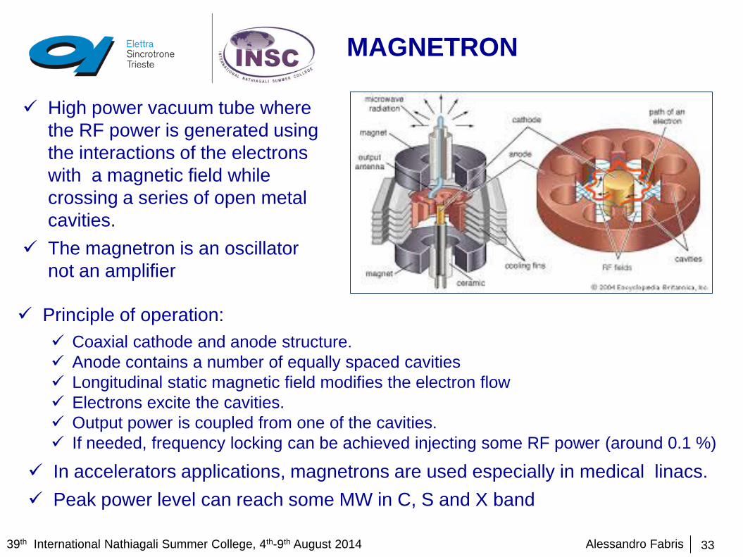
High power vacuum tube where the RF power is generated using the interactions of the electrons with a magnetic field while crossing a series of open metal cavities.
The magnetron is an oscillator not an amplifier
Principle of operation: Coaxial cathode and anode structure. Anode contains a number of equally spaced cavities Longitudinal static magnetic field modifies the electron flow Electrons excite the cavities. Output power is coupled from one of the cavities. If needed, frequency locking can be achieved injecting some RF power (around 0.1 %)
In accelerators applications, magnetrons are used especially in medical linacs. Peak power level can reach some MW in C, S and X band

Alessandro Fabris 39th International Nathiagali Summer College, 4th-9th August 2014
OTHER VACUUM TUBES
34
Travelling wave tube High power linear vacuum tube Helix TWT: bunching of the electron beam by the interaction with the RF field travelling
along an helix line which allows the energy transfer from the beam to the line
Gyrotron High powered linear beam vacuum tube which
generates millimiter wave electromagnetic waves exploiting the cyclotron resonance of electrons in a strong magnetic fields.
CW or pulse operation Output frequencies from 20 to 25 0 GHz Output power up to 1-2 MW
Wideband amplifier Operating from hundreds of MHz to tens of
GHz Output power up to few MW

Alessandro Fabris 39th International Nathiagali Summer College, 4th-9th August 2014
SOLID STATE
35
High power is achieved by combining a large number of transistor Pioneered at SOLEIL, now also at ESRF and other facilities
Courtesy of SOLEIL

Alessandro Fabris 39th International Nathiagali Summer College, 4th-9th August 2014
SOLID STATE
36
Different technologies available Silocon bipolar transistors Silicon LDMOS GaAsFET Static Induction Transistors (SITs)
Each module has a circulator Different combination elements are needed
ea
Pictures from SOLEIL

Alessandro Fabris 39th International Nathiagali Summer College, 4th-9th August 2014
SOLID STATE
37
High reliability due to redundancy
No high voltage
Used without high power circulator at the final output
Failure of single modules mainly due to thermal fatigue (transistor breakdown,
older damage for example)
Topology is an important aspect for maintainability and operability, also on long
term
Considering the fast development of the semiconductors market, already in
the design phase, the design should consider carefully how to assure an
enduring and long term maintenance.

Alessandro Fabris 39th International Nathiagali Summer College, 4th-9th August 2014
SOLID STATE -SUMMARY
38
FREQUENCY RANGE Up to 2 GHz BANDWIDTH large MAXIMUM POWER EXAMPLES 0.8 kW/module 200 kW/plant CLASS OF OPERATION A, AB EFFICIENCY 40 % RELIABILITY Good (redundancy) FEATURES Modular approach
Maintenance Graceful degradation No high voltage Efficiency Combination losses Module isolation

Alessandro Fabris 39th International Nathiagali Summer College, 4th-9th August 2014
SOLID STATE AMPLIFIERS EXAMPLES
39
SOLEIL SSA: Frequency: 352 MHz Output power: 180 kW 726 ×315 modules in 4 towers. 2 × Si LDMOS transistors per module.
ELBE Frequency: 1.3 GHz 20 kW 2 x 10 kW 9 power modules

Alessandro Fabris 39th International Nathiagali Summer College, 4th-9th August 2014
POWER TRANSMISSION
40
Alessandro Fabris 39th International Nathiagali Summer College, 4th-9th August 2014
GENERAL
41
The power transmission system is the assembly of components that perform the tasks to transport the RF power from the RF power source to the cavities.
This is accomplished by a network of coaxial lines or rigid rectangular waveguides. The choice of the system depends on the frequency and power levels involved Coaxial lines
No cut-off Higher attenuation Difficult to cool Typical ranges in use: frequency dc to 10 GHz, power rating example 1 MW at 200 MHz
Waveguides Cut-off Lower attenuation Easier to cool Higher frequency Higher power Typical ranges in use: frequency 0.32 to 352 GHz, power rating example 150 MW peak at 310 MHz
In addition to standard components, also special components are needed, like bends, directional couplers, circulators, loads, etc.

Alessandro Fabris 39th International Nathiagali Summer College, 4th-9th August 2014
COAXIAL LINES
42
TEM mode No cut-off, i.e. can be used down to d.c. Upper frequency limited by moding Higher attenuation than waveguides Difficult to cool Easier to handle than waveguides Characteristic impedance Z0
Phase velocity v For high power applications:
Air spaced lines, so dielectric is limited to support the inner conductor.
Rigid lines, either copper or aluminum Characteristic impedance is 50 ohm (ratio
between diameters is 2.3) Compromise between power handling
capabilities and attenuation.

Alessandro Fabris 39th International Nathiagali Summer College, 4th-9th August 2014
COAXIAL LINES
43

Alessandro Fabris 39th International Nathiagali Summer College, 4th-9th August 2014
COAXIAL LINES
44

Alessandro Fabris 39th International Nathiagali Summer College, 4th-9th August 2014
WAVEGUIDES
45
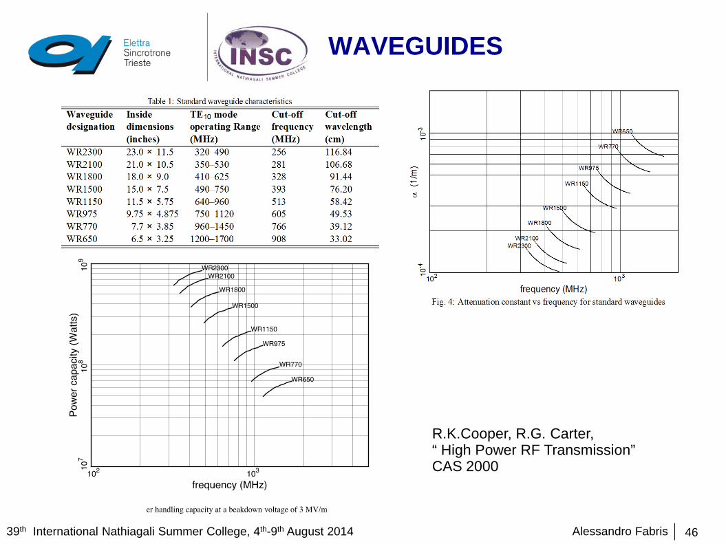
TE10 mode Most used rectangular waveguides with aspect ratio
2:1, but reduced height are also used. Cut-off frequency Roughly used approximately between 1.25 and 1.9 fc Lower attenuation Easier to cool Higher frequency than coaxial lines Higher power than coaxial line Pressurized waveguide to increase the breakdown
field strength In-vacuum waveguides Typically made in copper or aluminum.
Alessandro Fabris 39th International Nathiagali Summer College, 4th-9th August 2014
WAVEGUIDES
46
R.K.Cooper, R.G. Carter, “ High Power RF Transmission” CAS 2000

Alessandro Fabris 39th International Nathiagali Summer College, 4th-9th August 2014
COMPONENTS
47
2 port devices Bends
Coaxial bends Waveguide bends (E plane, H plane)
Twists Windows ………….
Three and four port devices Directional couplers Hybrids Magic Tees Phase shifters Variable attenuators ………..
Circulators Loads

Alessandro Fabris 39th International Nathiagali Summer College, 4th-9th August 2014
BENDS
48
Waveguide H-bend distorts or changes the magentic field to allow the
waveguide to bend in the required direction. It creates the bend around the thinner side.
Waveguide E-bend distorts or changes the electric field to allow the waveguide
to bend in the required direction) Meter or sweep Typical commercial mitre waveguide bends have VSWR around
1.03:1 over a 10% band Also other angles

Alessandro Fabris 39th International Nathiagali Summer College, 4th-9th August 2014
TWISTS AND WINDOWS
49
Twists Step or continuous Allow rotation of the electric field Typical 90, but also other angles Typical commercial waveguide
twists have VSWR around 1.05:1 over a 10% band
Window Separate parts of the waveguide
circuit under vacuum and in atmospheric pressure
Very critical component Typically made of high purity
alumina ceramic brazed in the transmission line

Alessandro Fabris 39th International Nathiagali Summer College, 4th-9th August 2014
DIRECTIONAL COUPLERS
50
Directional couplers are used to couple energy from the waveguides system to another system
They are mainly used to sample the fields in the waveguides for measurements and diagnostic purposes.
Typical parameter of commercial components over a 10 % bandwidth: VSWR 1.05 Coupling 6 to 60 dB Directivity 30 dB

Alessandro Fabris 39th International Nathiagali Summer College, 4th-9th August 2014
HYBRID AND MAGIC TEE
51
Typical commercial components equal 3 dB or unequal 4.77 and 6 dB 10 % bandwidth VSVR: 1/10:1 Amplitude balance: ±0.25 dB, phase balance: 90 ±2° Isolation: higher than 28 dB
Hybrid 4 port device Power supplied to one terminal
is ideally divided between two of the three remaining ports and nothing is coupled to the fourth one.
Used for power splitting and combining
Magic Tee 4 port device Combination of E type and H type Tee Used as power combiner or power splitter Signal from H arm is splitted to 1 and 2 in
phase Signal from E arm is splitted in 3 and 4 a
180° phase Signals fed from ports 1 and 2 are added in
the H pane port and subtracted in the E plane port
Typical commercial components 10 % bandwidth VSVR: 1/10:1 Colinear balance: ± 0.1 dB Inserton loss: less than 0.1 dB E-H isolation: higher than 30 dB

Alessandro Fabris 39th International Nathiagali Summer College, 4th-9th August 2014
PHASE SHIFTERS AND ATTENUATORS
52
At low power they can be built by placing dielectric or lossy material in the waveguide
At high power. Handling of the power could be problematic. Solution: exploit proprieties of hybrid junctions and use movable short
circuits instead of loads
Typical commercial components (phase shifter) 10 % bandwidth VSVR: 1.05:1 Insertion loss less than 0.1 dB Phase range higher than 360 °

Alessandro Fabris 39th International Nathiagali Summer College, 4th-9th August 2014
CIRCULATOR
53
Non reciprocal device. Ferrite material Basically they are used to isolate then power source and the cavity, so
that the reflected power is conveyed to a dummy load, where the power is dissipated.

Alessandro Fabris 39th International Nathiagali Summer College, 4th-9th August 2014
EXAMPLES
54
Waveguides for the 150 kW 500 MHz cw plant at elettra
Alessandro Fabris 39th International Nathiagali Summer College, 4th-9th August 2014
EXAMPLES
55
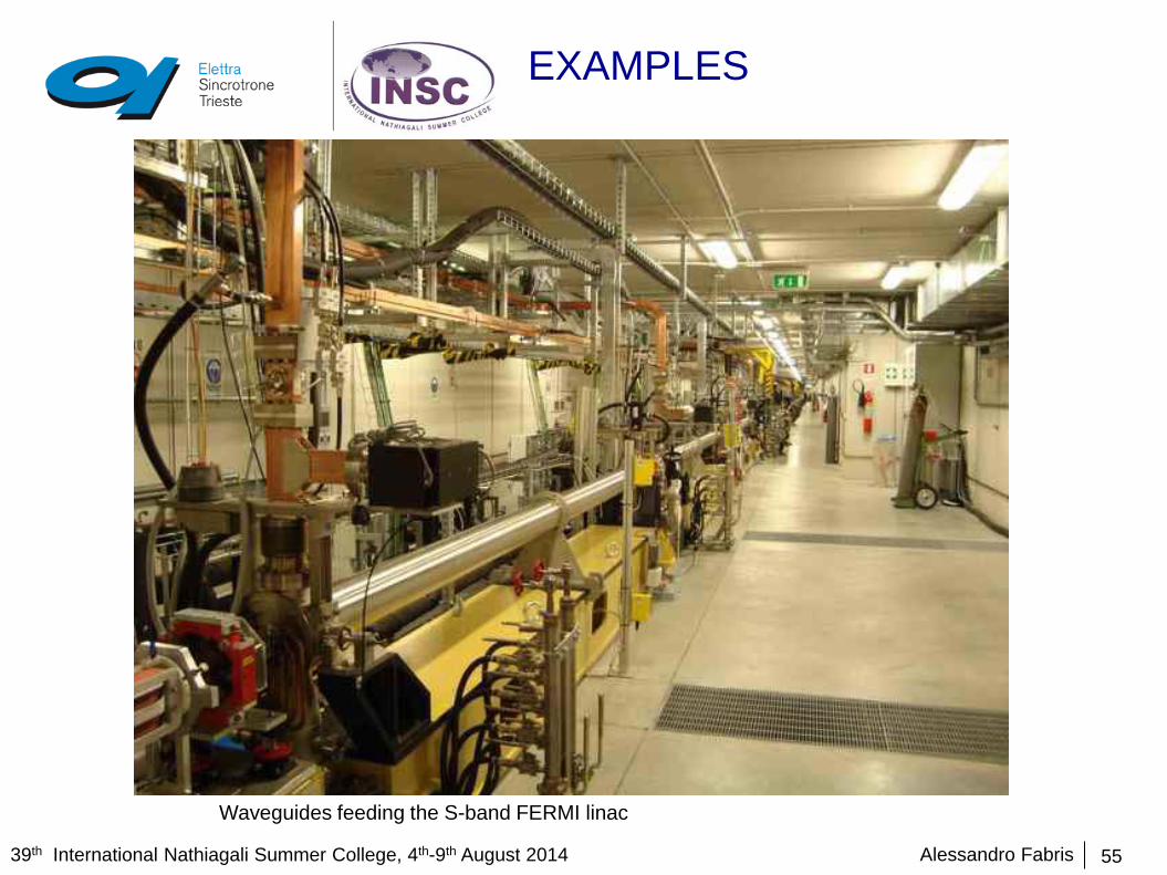
Waveguides feeding the S-band FERMI linac
Alessandro Fabris 39th International Nathiagali Summer College, 4th-9th August 2014
SUMMARY
56
Different alternatives are possible for high power generation and transmission. Choice depends on several aspects and there is no unique solutions. Some of the aspects to be considered:
• Power level • Frequency and duty cycle • Efficiency • Availability of the technology • Space • ……………..
This lecture is just to give a taste of the many technical and scientific aspects involved.
Some topics not covered: • SLED • Power supplies technology • Cooling • ……….

Alessandro Fabris 39th International Nathiagali Summer College, 4th-9th August 2014
Thank you!
57

Alessandro Fabris 39th International Nathiagali Summer College, 4th-9th August 2014
BIBLIOGRAPHY
58
1. R. E. Collin, Foundations for Microwave Engineering (McGraw Hill, New York, 1992).
2. J.C. Slater, Microwave Electronics, Dover Pub. Inc., (1969).
3. S. Ramo, J. R. Winery, and T. Van Duzer, Fields and Waves in Communication Electronics, 3rd ed. (Wiley, New York, 1994).
4. A. Gallo,RF System, CAS General Accelerator Physics 2010, Varna
5. R.G.Carter, RF Power Generations, CAS RF School 2010, Ebeltoft, Denmark.
6. B. Nelson, Introduction to Klystron Amplifiers and Travelling Tube Fundamentals, Varian Palo Alto Microwave Tube Division ,1978
7. H. Bohlen et al., Inductive output tubes for particle accelerators, Proc. EPAC 2004, Lucerne,
8. P. Marchand et al High Power 352 MHz Solid State Amplifiers at Synchrotron SOLEIL, Phys. Rev. ST Accel. Beams 10, 112001 (2007)
9. N. Marcuvitz, Waveguide Handbook, MIT Radiation Laboratory Series, Vol. 10, McGraw Hill 1951
10. R. K. Cooper, High power RF transmission, in Proceedings of the CERN Accelerator School: RF Engineering for Particle Accelerators, Oxford, UK, 1991
11. R. K. Cooper, R. G. Carter, High Power RF Transmission, in Proceedings of the CERN Accelerator School: Radio Frequency Engineering, 8-16 May 2000,
12. CERN Accelerator Schools (CAS) Proceedings.
13. Presentation at the 8th CWRF Workshop, Trieste 2014

Recommended