Intrinsically safe signal conditionersfor hazardous area applications
Intrinsically safe signal conditionersfor hazardous area applications
Intrinsically safe signal conditioners for hazardous area applications – Overview B.2
ACT20X – Overview B.4
Current supply isolator B.6
Current output isolator B.8
Temperature transducer B.10
Universal measurement and signal isolator-converter B.12
NAMUR isolating switching amplifier B.16
Valve control module B.20
Contents
B
Intri
nsica
lly sa
fe si
gnal
cond
ition
ers
for h
azar
dous
area
appli
catio
ns
B.11460730000 – 2014/2015
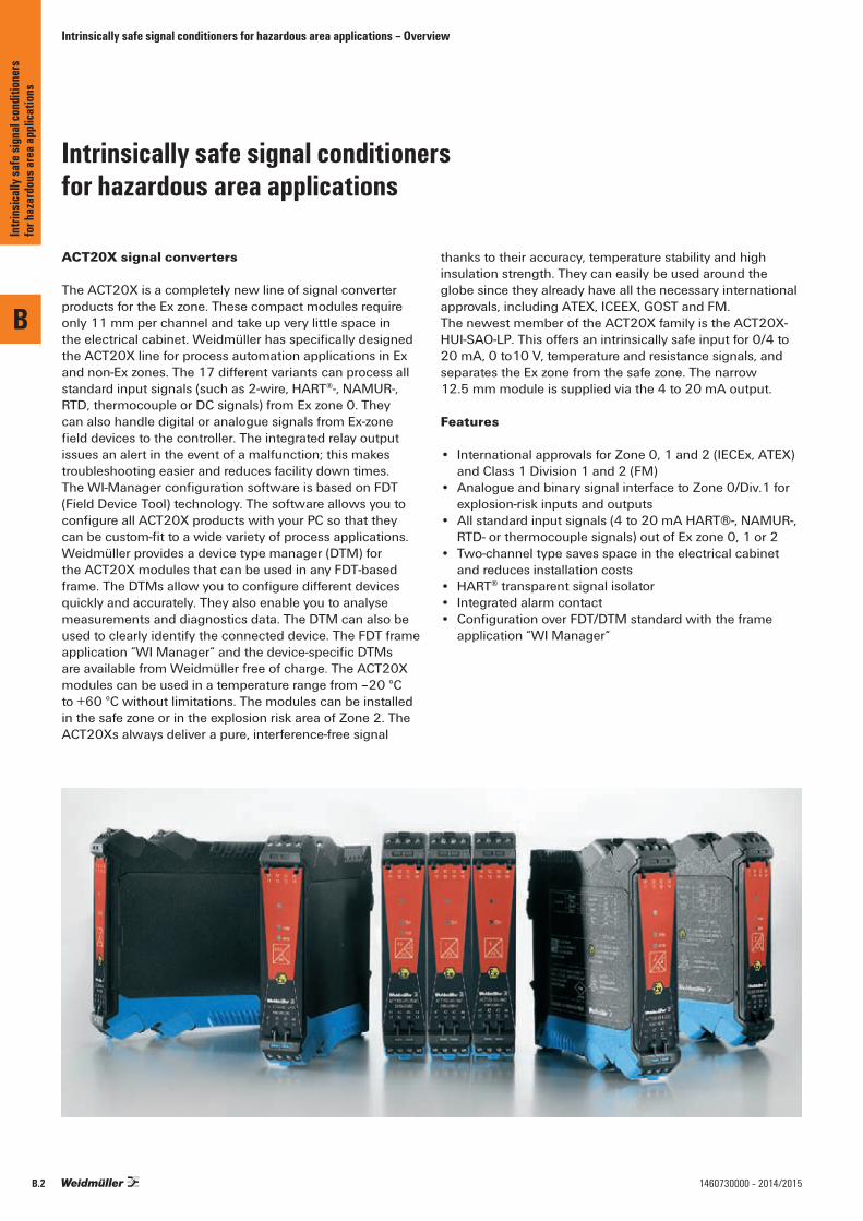
ACT20X signal converters
The ACT20X is a completely new line of signal converter products for the Ex zone. These compact modules require only 11 mm per channel and take up very little space in the electrical cabinet. Weidmüller has specifically designed the ACT20X line for process automation applications in Ex and non-Ex zones. The 17 different variants can process all standard input signals (such as 2-wire, HART®-, NAMUR-, RTD, thermocouple or DC signals) from Ex zone 0. They can also handle digital or analogue signals from Ex-zone field devices to the controller. The integrated relay output issues an alert in the event of a malfunction; this makes troubleshooting easier and reduces facility down times. The WI-Manager configuration software is based on FDT (Field Device Tool) technology. The software allows you to configure all ACT20X products with your PC so that they can be custom-fit to a wide variety of process applications. Weidmüller provides a device type manager (DTM) for the ACT20X modules that can be used in any FDT-based frame. The DTMs allow you to configure different devices quickly and accurately. They also enable you to analyse measurements and diagnostics data. The DTM can also be used to clearly identify the connected device. The FDT frame application “WI Manager“ and the device-specific DTMs are available from Weidmüller free of charge. The ACT20X modules can be used in a temperature range from –20 °C to +60 °C without limitations. The modules can be installed in the safe zone or in the explosion risk area of Zone 2. The ACT20Xs always deliver a pure, interference-free signal
thanks to their accuracy, temperature stability and high insulation strength. They can easily be used around the globe since they already have all the necessary international approvals, including ATEX, ICEEX, GOST and FM.The newest member of the ACT20X family is the ACT20X-HUI-SAO-LP. This offers an intrinsically safe input for 0/4 to 20 mA, 0 to10 V, temperature and resistance signals, and separates the Ex zone from the safe zone. The narrow 12.5 mm module is supplied via the 4 to 20 mA output.
Features
• International approvals for Zone 0, 1 and 2 (IECEx, ATEX)and Class 1 Division 1 and 2 (FM)
• Analogue and binary signal interface to Zone 0/Div.1 for explosion-risk inputs and outputs
• All standard input signals (4 to 20 mA HART®-, NAMUR-, RTD- or thermocouple signals) out of Ex zone 0, 1 or 2
• Two-channel type saves space in the electrical cabinet and reduces installation costs
• HART® transparent signal isolator• Integrated alarm contact • Configuration over FDT/DTM standard with the frame
application “WI Manager“
Intrinsically safe signal conditionersfor hazardous area applications
Intrinsically safe signal conditioners for hazardous area applications – Overview
B
Intri
nsica
lly sa
fe si
gnal
cond
ition
ers
for h
azar
dous
area
appli
catio
ns
B.2 1460730000 – 2014/2015
Intrinsically safe signal conditioners for hazardous area applications – Overview
ACT20X
B
Intri
nsica
lly sa
fe si
gnal
cond
ition
ers
for h
azar
dous
area
appli
catio
ns
B.31460730000 – 2014/2015
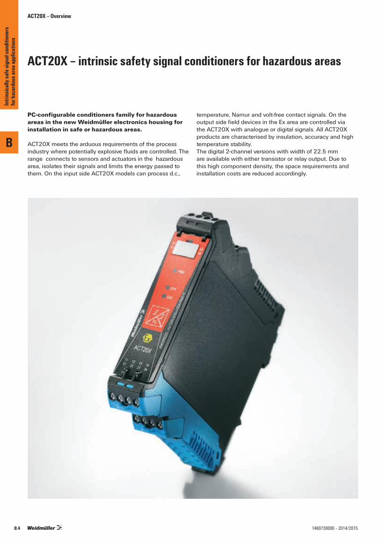
ACT20X – intrinsic safety signal conditioners for hazardous areas
PC-configurable conditioners family for hazardous areas in the new Weidmüller electronics housing for installation in safe or hazardous areas.
ACT20X meets the arduous requirements of the process industry where potentially explosive fluids are controlled. The range connects to sensors and actuators in the hazardous area, isolates their signals and limits the energy passed to them. On the input side ACT20X models can process d.c.,
temperature, Namur and volt-free contact signals. On the output side field devices in the Ex area are controlled via the ACT20X with analogue or digital signals. All ACT20X products are characterised by insulation, accuracy and high temperature stability.The digital 2-channel versions with width of 22.5 mm are available with either transistor or relay output. Due to this high component density, the space requirements and installation costs are reduced accordingly.
ACT20X – Overview
B
Intri
nsica
lly sa
fe si
gnal
cond
ition
ers
for h
azar
dous
area
appli
catio
ns
B.4 1460730000 – 2014/2015
ACT20X – Overview
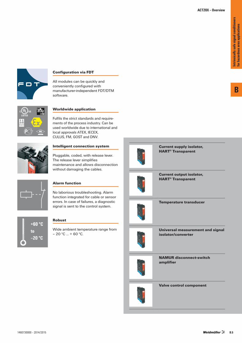
Configuration via FDT
All modules can be quickly and conveniently configured with manufacturer-independent FDT/DTM software.
Intelligent connection system
Pluggable, coded, with release lever.The release lever simplifies maintenance and allows disconnection without damaging the cables.
Worldwide application
Fulfils the strict standards and require-ments of the process industry. Can be used worldwide due to international and local approvals ATEX, IECEX, CULUS, FM, GOST and DNV.
Alarm function
No laborious troubleshooting. Alarm function integrated for cable or sensor errors. In case of failures, a diagnostic signal is sent to the control system.
Robust
Wide ambient temperature range from– 20 °C … + 60 °C.
\
;
"
Current supply isolator, HART® Transparent
Current output isolator, HART® Transparent
Temperature transducer
Universal measurement and signal isolator/converter
NAMUR disconnect-switch amplifier
Valve control component
+60 °Cto–20 °C
B
Intri
nsica
lly sa
fe si
gnal
cond
ition
ers
for h
azar
dous
area
appli
catio
ns
B.51460730000 – 2014/2015
ACT20X
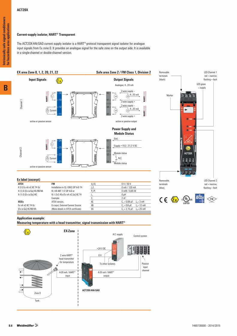
Current-supply isolator, HART® Transparent
The ACT20X-HAI-SAO current supply isolator is a HART®-protocol transparent signal isolator for analogue input signals from Ex zone 0. It provides an analogue signal for the safe zone on the output side. It is available in a single-channel or double-channel version.
EX area Zone 0, 1, 2, 20, 21, 22 Safe area Zone 2 / FM Class 1, Division 2
Chan
nel 1
:Ch
anne
l 2:
51
52
53
54
Input Signals
44
43
42
41
14
13
12
11
24
23
22
21
Output Signals
Gnd. -
Supply +19,2...31,2 V DC
Module status
Module status
mA mA4...20 mA+
–
42
41
44
43
–
+
– –mA mA
4...20 mA
Analogue, 4...20 mA
2-wire supply +
2-wire supply –
2-wire supply +
2-wire supply –
N.C.
active or passive sensor
active or passive outputactive or passive sensor
+
-Tx
+
-Current
+
-Tx
+
-Current
Power Supply andModule Status
Ex label (excerpt)ATEX FM Uo/Ui 0 V / 30 VII 3 G Ex nA nC IIC T4 Gc Installation in CL I DIV2 GP A-D T4
Kl. I-III ABT 1/2 GP A-G or Kl. I Zn2 AEx/Ex nA nC [ia] IIC T4
Io/li 0 mA / 120 mAII (1) G [Ex ia Ga] IIC/IIB/IIA Po/Pi 0 mW / 0,85 WII (1) D [Ex ia Da] IIIC Li 0 µH
Example: Ci 2 nFIECEx ATEX version,
Ex input, External Current Source:(More details in ATEX certificate)
IIC Co = 0,08 µF, Lo= 3 mHEx nA nC IIC T4 Gc IIB Co = 0,6 µF, Lo= 12 mH[Ex ia Ga] IIC/IIB/IIA IIA Co = 2,15 µF, Lo= 25 mH
Application example: Measuring temperature with a head transmitter, signal transmission with HART®
Control system
2 wire HART® head transmitter for temperature
Tank
A.C. supply
Zone 0ACT20X-HAI-SAO
To other isolators
+24 V DC
0 V
4-20 mA / HART® output
Passive input
channel4-20 mA / HART®
input
EX-Zone
\%
Removableterminals(black)
LED green= supply
Marker
Removableterminals(blue)
LED Channel 2red = inactive,
flashing = fault
LED Channel 1red = inactive,
flashing = fault
B
Intri
nsica
lly sa
fe si
gnal
cond
ition
ers
for h
azar
dous
area
appli
catio
ns
B.6 1460730000 – 2014/2015
B
B.71460730000 – 2014/2015
Current supply isolator
• Converts analogue signals from Ex zone 0 into analogue output signals for safe zones.
• Active and passive current inputs/outputs• HART® - transparent• PC configuration with FDT/DTM software, download
link at www.weidmueller.com• Relay output for failure alarm• 2-channel module, can also be used as a signal splitter
Technical dataInputInput currentSensor supplyResidual ripple (current loop) Output analogueOutput currentOutput signal limitload impedance current2-wire supplyAccuracyTemperature coefficientStep response timeCut-off frequency (-3 dB)Alarm outputType Nominal switching voltage
Continuous current
Power rating
General dataSupply voltagePower consumptionAmbient temperature / Storage temperatureApprovalsApprovalsInsulation coordinationInsulation voltageRated voltageEMC standards
DimensionsClamping range (nominal / min. / max.) mm²Depth x width x height mmNote
ACT20X-HAI-SAO-S / 2HAI-2SAO-S
I
I
PS
4...20 mA≤ 28 V DC< 7.5 mVeff
3.5 – 23 mA< 28 mA≤ 600 Ω≤ 26 V DC< 0.1% span< 0.01% of span/°C (TU)≤ 5 ms0.5…2.5 kHz @ 3.5…23 mA bi-directional HART® signal
Relay, 1 NC (voltage-free)≤ 125 V AC / 110 V DC (safe area) ≤ 32 V AC / 32 V DC (Zone 2)≤ 0.5 A AC / 0.3 A DC (safe zone), ≤ 0.5 A AC / 1 A DC ( Zone 2)
≤ 62.5 VA / 32 W (safe area) ≤ 16 VA / 32 W (Zone 2)
19.2 – 31.2 V DC≤ 3 W (2 channels)-20 °C...+60 °C / -20 °C...+85 °C
cULus; DEKRAATEX; DETNORVER; FMEX; GOSTEX; GOSTME25; IECEXDEK
2.6 kV (input / output)300 VDIN EN 61326
Type Qty. Order No.1-channel versionACT20X-HAI-SAO-S 1 ST 89654300002-channel versionACT20X-2HAI-2SAO-S 1 ST 8965440000
CBX200 USB configuration adapter - 8978580000
Ordering data
Screw connection2.5 / 0.5 / 2.5113.6 / 22.5 /
Intri
nsica
lly sa
fe si
gnal
cond
ition
ers
for h
azar
dous
area
appli
catio
ns
ACT20X
ACT20X
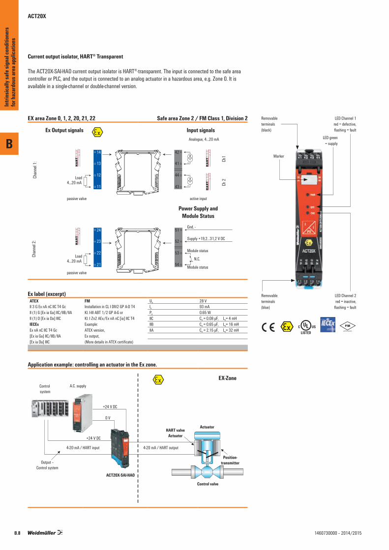
Current output isolator, HART® Transparent
The ACT20X-SAI-HAO current output isolator is HART®-transparent. The input is connected to the safe area controller or PLC, and the output is connected to an analog actuator in a hazardous area, e.g. Zone 0. It is available in a single-channel or double-channel version.
EX area Zone 0, 1, 2, 20, 21, 22 Safe area Zone 2 / FM Class 1, Division 2
Chan
nel 1
:Ch
anne
l 2:
51
52
53
54
Ex Output signals
44
43
42
41
14
13
12
11
24
23
22
21
Input signals
Gnd. -
Supply +19,2...31,2 V DC
Module status
Module status
42
41
44
43
Analogue, 4...20 mA
N.C.
passive valve
active inputpassive valve
Ch1
Ch 2Load
4...20 mA
Load4...20 mA
+
-
+
-
Power Supply andModule Status
Ex label (excerpt)ATEX FM Uo 28 VII 3 G Ex nA nC IIC T4 Gc Installation in CL I DIV2 GP A-D T4
Kl. I-III ABT 1/2 GP A-G or Kl. I Zn2 AEx/Ex nA nC [ia] IIC T4
Io 93 mAII (1) G [Ex ia Ga] IIC/IIB/IIA Po 0.65 WII (1) D [Ex ia Da] IIIC IIC Co = 0.08 µF, Lo= 4 mHIECEx Example: IIB Co = 0.65 µF, Lo= 16 mHEx nA nC IIC T4 Gc ATEX version, IIA Co = 2.15 µF, Lo= 32 mH[Ex ia Ga] IIC/IIB/IIA Ex output,[Ex ia Da] IIIC (More details in ATEX certificate)
Application example: controlling an actuator in the Ex zone.
Control system
A.C. supply
ACT20X-SAI-HAO
+24 V DC
0 V
4-20 mA / HART input
+24 V DC
Output –Control system
4-20 mA / HART output
HART valveActuator
Actuator
Position-transmitter
Control valve
EX-Zone
\%
Removableterminals(black)
LED green= supply
Marker
Removableterminals(blue)
LED Channel 2red = inactive,
flashing = fault
LED Channel 1red = defective,flashing = fault
B
Intri
nsica
lly sa
fe si
gnal
cond
ition
ers
for h
azar
dous
area
appli
catio
ns
B.8 1460730000 – 2014/2015
B
B.91460730000 – 2014/2015
Intri
nsica
lly sa
fe si
gnal
cond
ition
ers
for h
azar
dous
area
appli
catio
ns
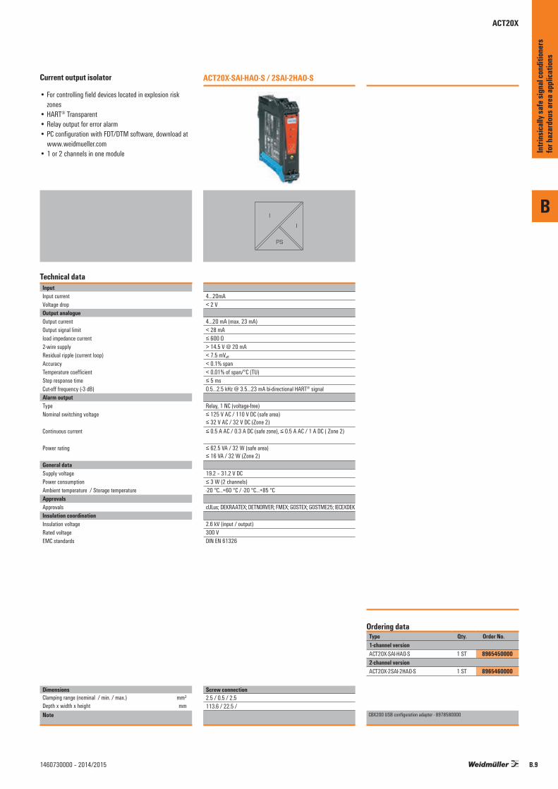
ACT20X
Current output isolator
• For controlling field devices located in explosion risk zones
• HART® Transparent• Relay output for error alarm• PC configuration with FDT/DTM software, download at
www.weidmueller.com• 1 or 2 channels in one module
Technical dataInputInput currentVoltage dropOutput analogueOutput currentOutput signal limitload impedance current2-wire supplyResidual ripple (current loop) AccuracyTemperature coefficientStep response timeCut-off frequency (-3 dB)Alarm outputType Nominal switching voltage
Continuous current
Power rating
General dataSupply voltagePower consumptionAmbient temperature / Storage temperatureApprovalsApprovalsInsulation coordinationInsulation voltageRated voltageEMC standards
DimensionsClamping range (nominal / min. / max.) mm²Depth x width x height mmNote
ACT20X-SAI-HAO-S / 2SAI-2HAO-S
I
I
PS
4…20mA< 2 V
4…20 mA (max. 23 mA)< 28 mA≤ 600 Ω > 14.5 V @ 20 mA< 7.5 mVeff
< 0.1% span< 0.01% of span/°C (TU)≤ 5 ms0.5…2.5 kHz @ 3.5…23 mA bi-directional HART® signal
Relay, 1 NC (voltage-free)≤ 125 V AC / 110 V DC (safe area) ≤ 32 V AC / 32 V DC (Zone 2)≤ 0.5 A AC / 0.3 A DC (safe zone), ≤ 0.5 A AC / 1 A DC ( Zone 2)
≤ 62.5 VA / 32 W (safe area) ≤ 16 VA / 32 W (Zone 2)
19.2 – 31.2 V DC≤ 3 W (2 channels)-20 °C...+60 °C / -20 °C...+85 °C
cULus; DEKRAATEX; DETNORVER; FMEX; GOSTEX; GOSTME25; IECEXDEK
2.6 kV (input / output)300 VDIN EN 61326
Type Qty. Order No.1-channel versionACT20X-SAI-HAO-S 1 ST 89654500002-channel versionACT20X-2SAI-2HAO-S 1 ST 8965460000
CBX200 USB configuration adapter - 8978580000
Ordering data
Screw connection2.5 / 0.5 / 2.5113.6 / 22.5 /
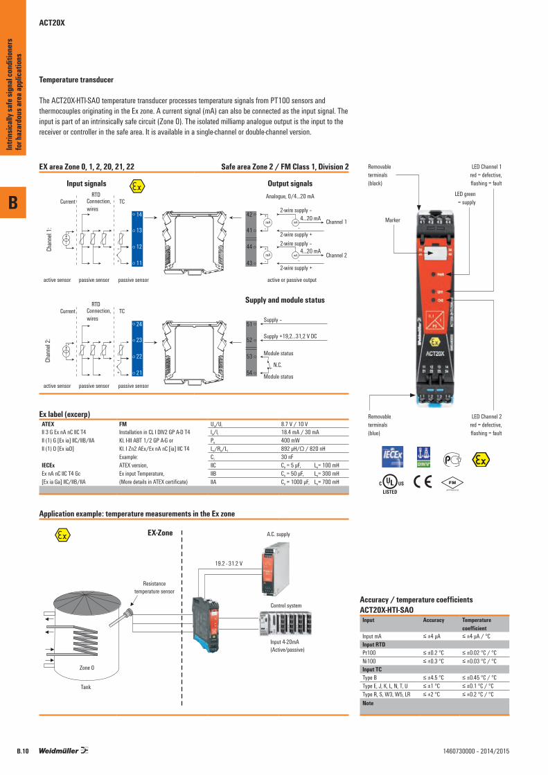
ACT20X
Temperature transducer
The ACT20X-HTI-SAO temperature transducer processes temperature signals from PT100 sensors and thermocouples originating in the Ex zone. A current signal (mA) can also be connected as the input signal. The input is part of an intrinsically safe circuit (Zone 0). The isolated milliamp analogue output is the input to the receiver or controller in the safe area. It is available in a single-channel or double-channel version.
EX area Zone 0, 1, 2, 20, 21, 22 Safe area Zone 2 / FM Class 1, Division 2
Ex label (excerp)ATEX FM Uo/Ui 8.7 V / 10 VII 3 G Ex nA nC IIC T4 Installation in CL I DIV2 GP A-D T4
Kl. I-III ABT 1/2 GP A-G or Kl. I Zn2 AEx/Ex nA nC [ia] IIC T4
Io/li 18.4 mA / 30 mAII (1) G [Ex ia] IIC/IIB/IIA Po 400 mWII (1) D [Ex iaD] Lo/Ro/Li 892 µH/Ω / 820 nH
Example: Ci 30 nFIECEx ATEX version, IIC Co = 5 µF, Lo= 100 mHEx nA nC IIC T4 Gc Ex input Temperature, IIB Co = 50 µF, Lo= 300 mH[Ex ia Ga] IIC/IIB/IIA (More details in ATEX certificate) IIA Co = 1000 µF, Lo= 700 mH
Application example: temperature measurements in the Ex zone
Control system
Resistancetemperature sensor
Tank
Zone 0
EX-Zone
19.2 - 31.2 V
A.C. supply
Input 4-20mA(Active/passive)
Accuracy / temperature coefficients ACT20X-HTI-SAO
Input Accuracy Temperature coefficient
Input mA ≤ ±4 μA ≤ ±4 μA / °CInput RTDPt100 ≤ ±0.2 °C ≤ ±0.02 °C / °CNi100 ≤ ±0.3 °C ≤ ±0.03 °C / °CInput TCType B ≤ ±4.5 °C ≤ ±0.45 °C / °CType E, J, K, L, N, T, U ≤ ±1 °C ≤ ±0.1 °C / °CType R, S, W3, W5, LR ≤ ±2 °C ≤ ±0.2 °C / °CNote
\ %
Removableterminals(black)
LED green= supply
Marker
Removableterminals(blue)
LED Channel 2red = defective,flashing = fault
LED Channel 1red = defective,flashing = fault
B
Intri
nsica
lly sa
fe si
gnal
cond
ition
ers
for h
azar
dous
area
appli
catio
ns
B.10 1460730000 – 2014/2015
B
B.111460730000 – 2014/2015
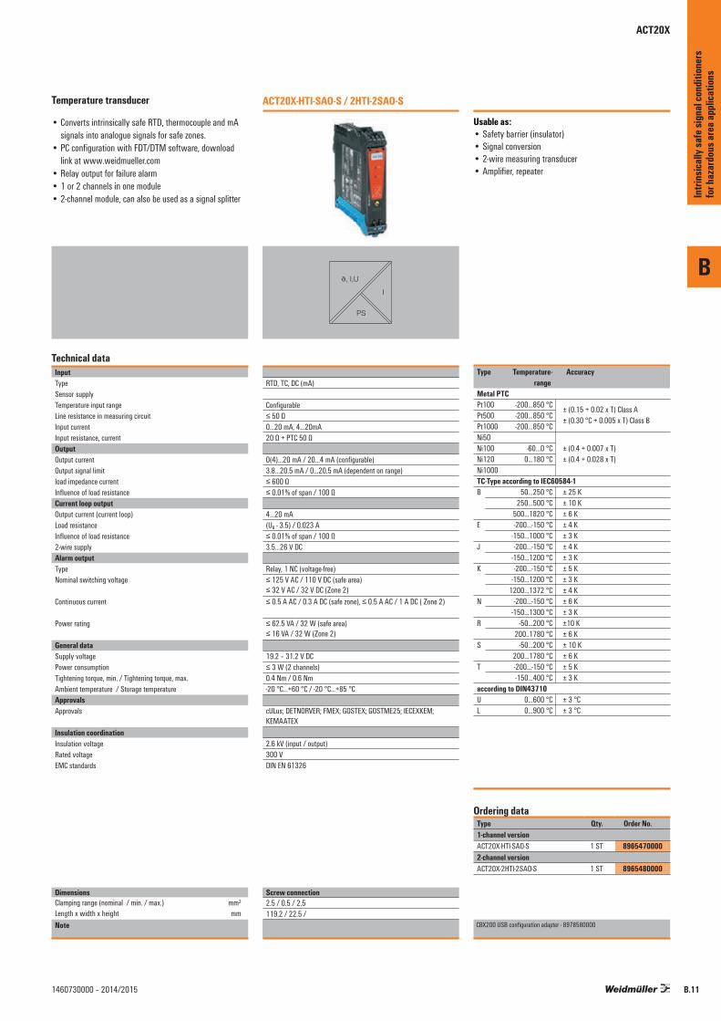
Temperature transducer
• Converts intrinsically safe RTD, thermocouple and mA signals into analogue signals for safe zones.
• PC configuration with FDT/DTM software, download link at www.weidmueller.com
• Relay output for failure alarm• 1 or 2 channels in one module• 2-channel module, can also be used as a signal splitter
Technical dataInputTypeSensor supplyTemperature input rangeLine resistance in measuring circuitInput currentInput resistance, currentOutputOutput currentOutput signal limitload impedance currentInfluence of load resistanceCurrent loop outputOutput current (current loop)Load resistanceInfluence of load resistance 2-wire supplyAlarm outputType Nominal switching voltage
Continuous current
Power rating
General dataSupply voltagePower consumptionTightening torque, min. / Tightening torque, max.Ambient temperature / Storage temperatureApprovalsApprovals
Insulation coordinationInsulation voltageRated voltageEMC standards
DimensionsClamping range (nominal / min. / max.) mm²Length x width x height mmNote
ACT20X-HTI-SAO-S / 2HTI-2SAO-S
J, I,U
I
PS
RTD, TC, DC (mA)
Configurable≤ 50 Ω0...20 mA, 4…20mA20 Ω + PTC 50 Ω
0(4)…20 mA / 20…4 mA (configurable)3.8…20.5 mA / 0…20.5 mA (dependent on range)≤ 600 Ω≤ 0.01% of span / 100 Ω
4…20 mA(UB - 3.5) / 0.023 A≤ 0.01% of span / 100 Ω3.5…26 V DC
Relay, 1 NC (voltage-free)≤ 125 V AC / 110 V DC (safe area) ≤ 32 V AC / 32 V DC (Zone 2)≤ 0.5 A AC / 0.3 A DC (safe zone), ≤ 0.5 A AC / 1 A DC ( Zone 2)
≤ 62.5 VA / 32 W (safe area) ≤ 16 VA / 32 W (Zone 2)
19.2 – 31.2 V DC≤ 3 W (2 channels)0.4 Nm / 0.6 Nm-20 °C...+60 °C / -20 °C...+85 °C
cULus; DETNORVER; FMEX; GOSTEX; GOSTME25; IECEXKEM; KEMAATEX
2.6 kV (input / output)300 VDIN EN 61326
Type Qty. Order No.1-channel versionACT20X-HTI-SAO-S 1 ST 89654700002-channel versionACT20X-2HTI-2SAO-S 1 ST 8965480000
CBX200 USB configuration adapter - 8978580000
Ordering data
Screw connection2.5 / 0.5 / 2.5119.2 / 22.5 /
Intri
nsica
lly sa
fe si
gnal
cond
ition
ers
for h
azar
dous
area
appli
catio
ns
ACT20X
ACT20X
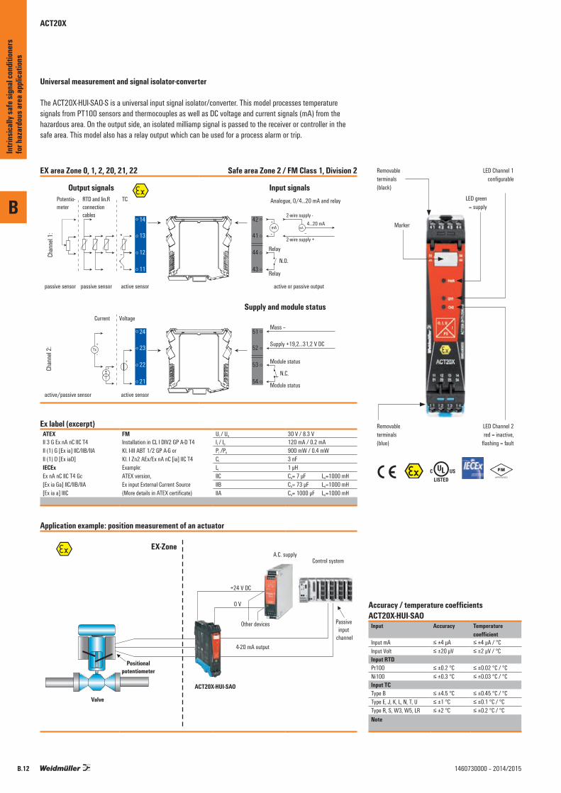
Universal measurement and signal isolator-converter
The ACT20X-HUI-SAO-S is a universal input signal isolator/converter. This model processes temperature signals from PT100 sensors and thermocouples as well as DC voltage and current signals (mA) from the hazardous area. On the output side, an isolated milliamp signal is passed to the receiver or controller in the safe area. This model also has a relay output which can be used for a process alarm or trip.
EX area Zone 0, 1, 2, 20, 21, 22 Safe area Zone 2 / FM Class 1, Division 2
Ex label (excerpt)ATEX FM Ui / Uo 30 V / 8.3 VII 3 G Ex nA nC IIC T4 Installation in CL I DIV2 GP A-D T4
Kl. I-III ABT 1/2 GP A-G or Kl. I Zn2 AEx/Ex nA nC [ia] IIC T4
Ii / Io 120 mA / 0.2 mAII (1) G [Ex ia] IIC/IIB/IIA Pi /Po 900 mW / 0.4 mWII (1) D [Ex iaD] Ci 3 nFIECEx Example: Li 1 μHEx nA nC IIC T4 Gc ATEX version, IIC Co= 7 μF Lo=1000 mH[Ex ia Ga] IIC/IIB/IIA Ex input External Current Source IIB Co= 73 μF Lo=1000 mH[Ex ia a] IIIC (More details in ATEX certificate) IIA Co= 1000 μF Lo=1000 mH
Application example: position measurement of an actuator
Control systemA.C. supply
ACT20X-HUI-SAO
Other devices
+24 V DC
0 V
4-20 mA output
Passive input
channel
EX-Zone
Positionalpotentiometer
Valve
Accuracy / temperature coefficients ACT20X-HUI-SAO
Input Accuracy Temperature coefficient
Input mA ≤ ±4 μA ≤ ±4 μA / °CInput Volt ≤ ±20 μV ≤ ±2 μV / °CInput RTDPt100 ≤ ±0.2 °C ≤ ±0.02 °C / °CNi100 ≤ ±0.3 °C ≤ ±0.03 °C / °CInput TCType B ≤ ±4.5 °C ≤ ±0.45 °C / °CType E, J, K, L, N, T, U ≤ ±1 °C ≤ ±0.1 °C / °CType R, S, W3, W5, LR ≤ ±2 °C ≤ ±0.2 °C / °CNote
\%
Removableterminals(black)
LED green= supply
Marker
Removableterminals(blue)
LED Channel 2red = inactive,
flashing = fault
LED Channel 1configurable
B
Intri
nsica
lly sa
fe si
gnal
cond
ition
ers
for h
azar
dous
area
appli
catio
ns
B.12 1460730000 – 2014/2015
B
B.131460730000 – 2014/2015
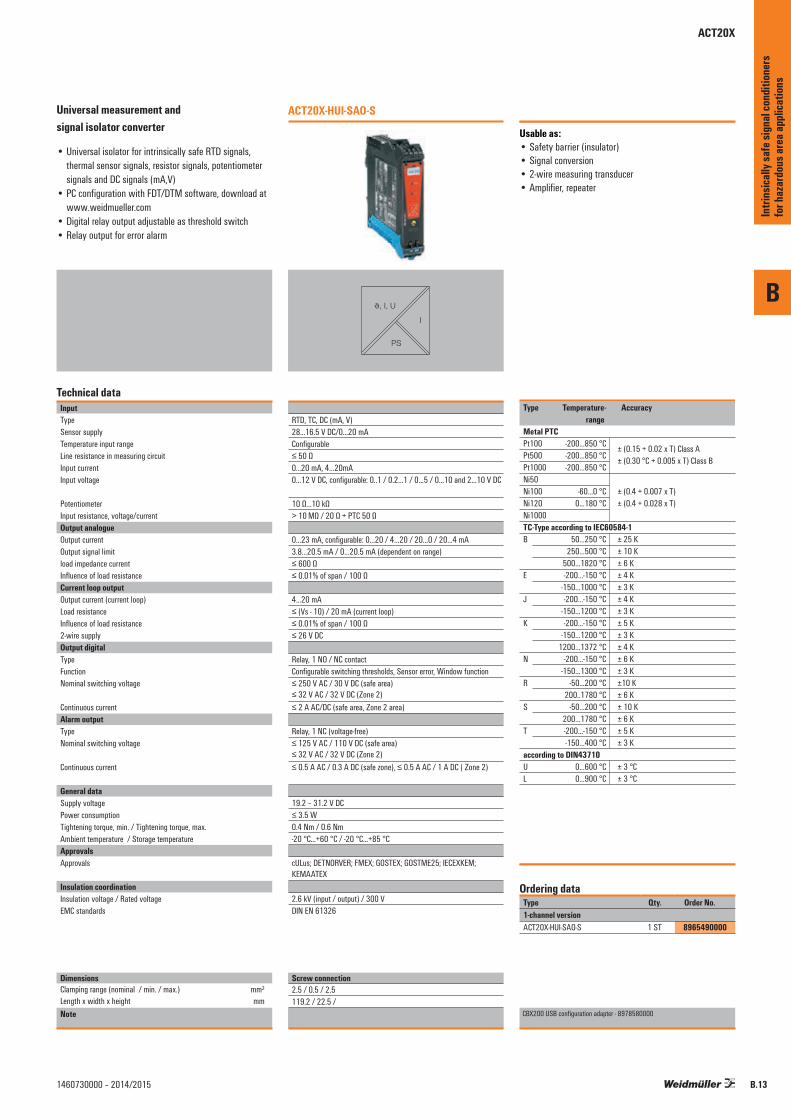
Universal measurement and signal isolator converter
• Universal isolator for intrinsically safe RTD signals, thermal sensor signals, resistor signals, potentiometer signals and DC signals (mA,V)
• PC configuration with FDT/DTM software, download at www.weidmueller.com
• Digital relay output adjustable as threshold switch• Relay output for error alarm
Technical dataInputTypeSensor supplyTemperature input rangeLine resistance in measuring circuitInput currentInput voltage
PotentiometerInput resistance, voltage/currentOutput analogueOutput currentOutput signal limitload impedance currentInfluence of load resistanceCurrent loop outputOutput current (current loop)Load resistanceInfluence of load resistance 2-wire supplyOutput digitalType Function Nominal switching voltage
Continuous current Alarm outputType Nominal switching voltage
Continuous current
General dataSupply voltagePower consumptionTightening torque, min. / Tightening torque, max.Ambient temperature / Storage temperatureApprovalsApprovals
Insulation coordinationInsulation voltage / Rated voltageEMC standards
DimensionsClamping range (nominal / min. / max.) mm²Length x width x height mmNote
ACT20X-HUI-SAO-S
J, I, U
I
PS
RTD, TC, DC (mA, V)28...16.5 V DC/0…20 mAConfigurable≤ 50 Ω0...20 mA, 4…20mA0…12 V DC, configurable: 0..1 / 0.2…1 / 0…5 / 0…10 and 2…10 V DC
10 Ω…10 kΩ> 10 MΩ / 20 Ω + PTC 50 Ω
0…23 mA, configurable: 0…20 / 4…20 / 20…0 / 20…4 mA3.8…20.5 mA / 0…20.5 mA (dependent on range)≤ 600 Ω≤ 0.01% of span / 100 Ω
4…20 mA≤ (Vs - 10) / 20 mA (current loop)≤ 0.01% of span / 100 Ω≤ 26 V DC
Relay, 1 NO / NC contactConfigurable switching thresholds, Sensor error, Window function≤ 250 V AC / 30 V DC (safe area) ≤ 32 V AC / 32 V DC (Zone 2)≤ 2 A AC/DC (safe area, Zone 2 area)
Relay, 1 NC (voltage-free)≤ 125 V AC / 110 V DC (safe area) ≤ 32 V AC / 32 V DC (Zone 2)≤ 0.5 A AC / 0.3 A DC (safe zone), ≤ 0.5 A AC / 1 A DC ( Zone 2)
19.2 – 31.2 V DC≤ 3.5 W0.4 Nm / 0.6 Nm-20 °C...+60 °C / -20 °C...+85 °C
cULus; DETNORVER; FMEX; GOSTEX; GOSTME25; IECEXKEM; KEMAATEX
2.6 kV (input / output) / 300 VDIN EN 61326
Type Qty. Order No.1-channel versionACT20X-HUI-SAO-S 1 ST 8965490000
CBX200 USB configuration adapter - 8978580000
Ordering data
Screw connection2.5 / 0.5 / 2.5119.2 / 22.5 /
Intri
nsica
lly sa
fe si
gnal
cond
ition
ers
for h
azar
dous
area
appli
catio
ns
ACT20X
ACT20X
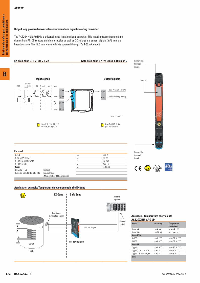
Output loop powered universal measurement and signal isolating converter
The ACT20X-HUI-SAO-LP is a universal input, isolating signal converter. This model processes temperature signals from PT100 sensors and thermocouples as well as DC voltage and current signals (mA) from the hazardous area. The 12.5 mm wide module is powered through it‘s 4-20 mA output.
EX area Zone 0, 1, 2, 20, 21, 22 Safe area Zone 2 / FM Class 1, Division 2
Input signals Output signals
41
42
11
12
21
22
- Loop Powered (4-20 mA)
+Loop Powered (4-20 mA)
-20 ≤ Ta ≤ +60 °C
VoltPOTRTD/RES
3-wire2-wire TC mV mA
+
+
+
-
Zone 0, 1, 2, 20, 21, 22 /Cl. I/II/III, div. 1 gr. A-G
Zone 2 / FM Cl. 1, div. 2,gr. A-D or safe area
Ex label ATEX Uo 5.88 VII 3 G Ex nA nC IIC T4 Io 3.1 mA II (1) G [Ex ia] IIC/IIB/IIA Po 4.6 mWII (1) D [Ex iaD] Ci 0.001 μFIECEx Li negligibleEx nA IIC T4 Gc Example:[Ex ia Ma Ga] I/IIC [Ex ia Da] IIIC IECEx version
(More details in IECEx certificate)
Application example: Temperature measurement in the EX-zone
Resistancetemperature sensor
Tank
Zone 0
EX-Zone Safe Zone
ACT20X-HUI-SAO
Controlsystem
4-20 mA Output
Input channel active
Accuracy / temperature coefficients ACT20X-HUI-SAO-LP
Input Accuracy Temperature coefficient
Input mA ≤ ±4 μA ≤ ±4 μA / °CInput Volt ≤ ±20 μV ≤ ±2 μV / °CInput RTDPt100 ≤ ±0.2 °C ≤ ±0.02 °C / °CNi100 ≤ ±0.3 °C ≤ ±0.03 °C / °CInput TCType B ≤ ±4.5 °C ≤ ±0.45 °C / °CType E, J, K, L, N, T, U ≤ ±1 °C ≤ ±0.1 °C / °CType R , S, W3, W5, LR ≤ ±2 °C ≤ ±0.2 °C / °CNote
\%
Removableterminals(black)
Marker
Removableterminals(blue)
B
Intri
nsica
lly sa
fe si
gnal
cond
ition
ers
for h
azar
dous
area
appli
catio
ns
B.14 1460730000 – 2014/2015
B
B.151460730000 – 2014/2015
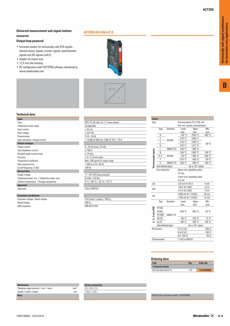
Universal measurement and signal isolator-converter Output-loop powered• Universal isolator for intrinsically safe RTD signals,
thermal sensor signals, resistor signals, potentiometer signals and DC signals (mA,V)
• Supply via output loop• 12.5 mm thin housing• PC configuration with FDT/DTM software, download at
www.weidmueller.com
Technical dataInputTypeTemperature input rangeInput currentInput voltagePotentiometerInput resistance, voltage/currentOutput analogueOutput currentload impedance currentResidual ripple (current loop) AccuracyTemperature coefficientStep response timeCut-off frequency (-3 dB)General dataSupply voltageTightening torque, min. / Tightening torque, max.Ambient temperature / Storage temperatureApprovalsApprovals
Insulation coordinationInsulation voltage / Rated voltageRated voltageEMC standards
DimensionsClamping range (nominal / min. / max.) mm²Length x width x height mmNote
ACT20X-HUI-SAO-LP-S
J, I, U
I
RTD, TC, DC (mA, V), 2 - 3 wire resistorConfigurable± 25 mA± 28 V DC10 Ω…10 kΩ> 10 MΩ @ 600 mV, 2 MΩ @ 28 V / 70 Ω
4…20 mA (max. 23 mA)≤ 700 Ω≤ 10 mVss
< 0.1 % of end valueMax. 200 ppm/K of output range< 400 ms (10…90 %)100 Hz
11…28 V DC (loop powered)0.4 Nm / 0.6 Nm0 °C...+60 °C / -20 °C...+70 °C
cULus; GOSTEX
4 kV (input / output) / 300 Veff
300 Veff
DIN EN 61326
InputsType Thermocouples (TC), RTD, mA,
Volt, mV, resistor, potentiometer
Ther
moco
uple
input
s
Type Standard Lower limit
Upper limit
Min. area
B
IEC584
100 °C 1820 °C 400 °CE -270 °C 1000 °C
80 °CJ -270 °C 1200 °CK -270 °C 1372 °CL DIN43710 -100 °C 900 °CN
IEC584-180 °C 1300 °C 100 °C
R, S -50 °C 1768 °C 300 °CT -270 °C 400 °C 80 °CU DIN43710 -200 °C 600 °C 100 °C
User-defined Input Up to 101 valuesError detection Upper error signalling value:
23 mA,Lower error signalling value: 3,5 mA
mA ±25 mA @ 70 Ω 4 mA
Volt±28 V @ 2 MΩ 2,0 V±12 V @ 2 MΩ 1,0 V
mV±600 mV @ >10 MΩ 50 mV±150 mV @ >10 MΩ 15 mV
2-, 3-
, 4-w
ire R
TD Pt100, Pt200
DIN43710-200 °C 850 °C -20 °C
Pt1000Ni120 -80 °C 320 °C 15 °CCu10 -100 °C 260 °C 100 °CUser-defined Input Up to 101 values
Resistance 0 to12 kΩ 500 Ω0 to15 kΩ 100 Ω0 to 750 Ω 50 Ω
Potentiometer 1.2 kΩ to 500 kΩ
Type Standard Lower limit
Upper limit
Min. area
Type Qty. Order No.1-channel versionACT20X-HUI-SAO-LP-S 1 ST 1318220000
CBX200 USB configuration adapter - 8978580000
Ordering data
Screw connection2.5 / 0.5 / 2.5119.2 / 12.5 /
Intri
nsica
lly sa
fe si
gnal
cond
ition
ers
for h
azar
dous
area
appli
catio
ns
ACT20X
ACT20X
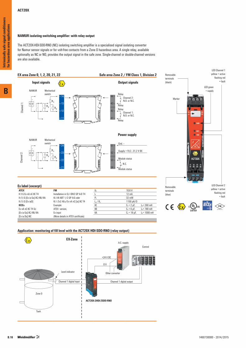
NAMUR isolating switching amplifier: with relay output
The ACT20X-HDI-SDO-RNO (NC) isolating switching amplifier is a specialised signal isolating converter for Namur sensor signals or for volt-free contacts from a Zone 0 hazardous area. A single relay, available optionally as NC or NO, provides the output signal in the safe zone. Single-channel or double-channel versions are also available.
EX area Zone 0, 1, 2, 20, 21, 22 Safe area Zone 2 / FM Class 1, Division 2
Chan
nel 1
:Ch
anne
l 2:
51
52
53
54
Input signals
44
43
42
41
14
13
12
11
24
23
22
21
Output signals
Gnd. –
Supply +19,2...31,2 V DC
Module status
Module status
44
43
42
41
N.C.
Power supply
Relay
Relay
RelayChannel 1:N.O. or N.C.
Relay
Channel 2:N.O. or N.C.
NAMUR
+
– Rp
Rs
Rp
Mechanicalswitch
NAMUR
+
– Rp
Rs
Rp
Mechanicalswitch
Ex label (excerpt)ATEX FM Uo 10.6 VII 3 G Ex nA nC IIC T4 Installation in CL I DIV2 GP A-D T4
Kl. I-III ABT 1/2 GP A-G oder Kl. I Zn2 AEx/Ex nA nC [ia] IIC T4
Io 12 mAII (1) G [Ex ia Ga] IIC/IIB/IIA Po 32 mWII (1) D [Ex iaD] Lo / Ro 1150 µH/ΩIECEx Example: IIC Co = 2 µF, Lo= 260 mHEx nA nC IIC T4 Gc ATEX version, IIB Co = 6 µF, Lo= 780 mH[Ex ia Ga] IIC/IIB/IIA Ex input IIA Co = 18 µF, Lo= 1000 mH[Ex ia Da] IIIC (More details in ATEX certificate)
Application: monitoring of fill level with the ACT20X HDI-SDO-RNO (relay output)
\%
Removableterminals(black)
LED green= supply
Marker
Removableterminals(blue)
LED Channel 2yellow = active
flashing red= fault
LED Channel 1yellow = active
flashing red = fault
B
Intri
nsica
lly sa
fe si
gnal
cond
ition
ers
for h
azar
dous
area
appli
catio
ns
B.16 1460730000 – 2014/2015
B
B.171460730000 – 2014/2015
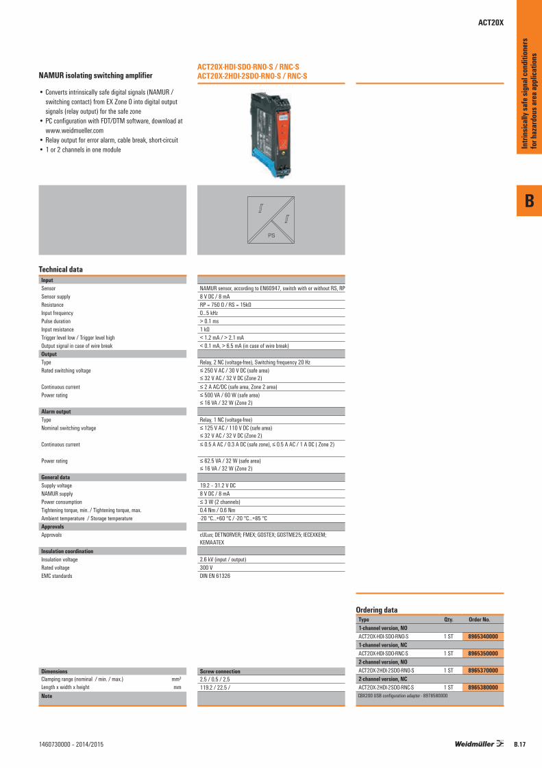
NAMUR isolating switching amplifier
• Converts intrinsically safe digital signals (NAMUR / switching contact) from EX Zone 0 into digital output signals (relay output) for the safe zone
• PC configuration with FDT/DTM software, download at www.weidmueller.com
• Relay output for error alarm, cable break, short-circuit• 1 or 2 channels in one module
Technical dataInputSensorSensor supplyResistanceInput frequencyPulse durationInput resistanceTrigger level low / Trigger level highOutput signal in case of wire breakOutputType Rated switching voltage
Continuous currentPower rating
Alarm outputType Nominal switching voltage
Continuous current
Power rating
General dataSupply voltageNAMUR supplyPower consumptionTightening torque, min. / Tightening torque, max.Ambient temperature / Storage temperatureApprovalsApprovals
Insulation coordinationInsulation voltageRated voltageEMC standards
DimensionsClamping range (nominal / min. / max.) mm²Length x width x height mmNote
ACT20X-HDI-SDO-RNO-S / RNC-S ACT20X-2HDI-2SDO-RNO-S / RNC-S
PS
NAMUR sensor, according to EN60947, switch with or without RS, RP8 V DC / 8 mARP = 750 Ω / RS = 15kΩ0...5 kHz> 0.1 ms1 kΩ< 1.2 mA / > 2.1 mA< 0.1 mA, > 6.5 mA (in case of wire break)
Relay, 2 NC (voltage-free), Switching frequency 20 Hz≤ 250 V AC / 30 V DC (safe area) ≤ 32 V AC / 32 V DC (Zone 2)≤ 2 A AC/DC (safe area, Zone 2 area)≤ 500 VA / 60 W (safe area) ≤ 16 VA / 32 W (Zone 2)
Relay, 1 NC (voltage-free)≤ 125 V AC / 110 V DC (safe area) ≤ 32 V AC / 32 V DC (Zone 2)≤ 0.5 A AC / 0.3 A DC (safe zone), ≤ 0.5 A AC / 1 A DC ( Zone 2)
≤ 62.5 VA / 32 W (safe area) ≤ 16 VA / 32 W (Zone 2)
19.2 – 31.2 V DC8 V DC / 8 mA≤ 3 W (2 channels)0.4 Nm / 0.6 Nm-20 °C...+60 °C / -20 °C...+85 °C
cULus; DETNORVER; FMEX; GOSTEX; GOSTME25; IECEXKEM; KEMAATEX
2.6 kV (input / output)300 VDIN EN 61326
Type Qty. Order No.1-channel version, NOACT20X-HDI-SDO-RNO-S 1 ST 89653400001-channel version, NCACT20X-HDI-SDO-RNC-S 1 ST 89653500002-channel version, NOACT20X-2HDI-2SDO-RNO-S 1 ST 89653700002-channel version, NCACT20X-2HDI-2SDO-RNC-S 1 ST 8965380000CBX200 USB configuration adapter - 8978580000
Ordering data
Screw connection2.5 / 0.5 / 2.5119.2 / 22.5 /
Intri
nsica
lly sa
fe si
gnal
cond
ition
ers
for h
azar
dous
area
appli
catio
ns
ACT20X
ACT20X
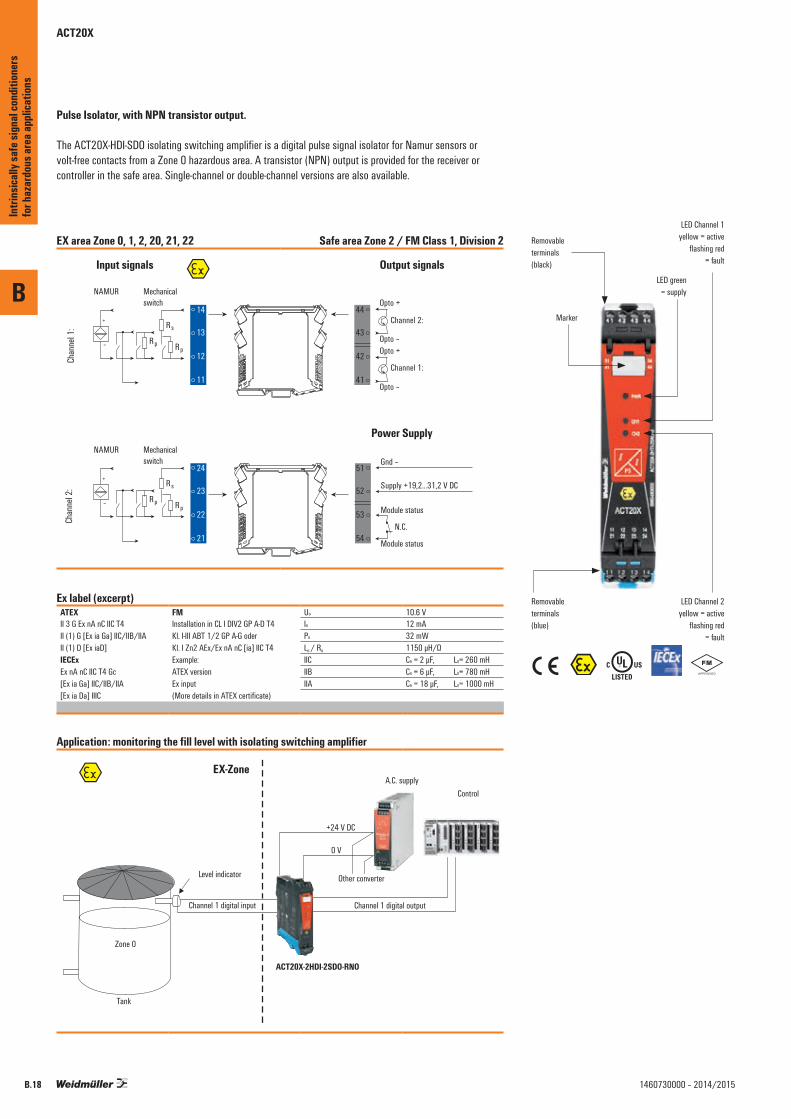
Pulse Isolator, with NPN transistor output.
The ACT20X-HDI-SDO isolating switching amplifier is a digital pulse signal isolator for Namur sensors or volt-free contacts from a Zone 0 hazardous area. A transistor (NPN) output is provided for the receiver or controller in the safe area. Single-channel or double-channel versions are also available.
EX area Zone 0, 1, 2, 20, 21, 22 Safe area Zone 2 / FM Class 1, Division 2
Chan
nel 1
:Ch
anne
l 2:
51
52
53
54
Input signals
44
43
42
41
14
13
12
11
24
23
22
21
Output signals
Gnd –
Supply +19,2...31,2 V DC
Module status
Module status
44
43
42
41
N.C.
Power Supply
NAMUR
+
– Rp
Rs
Rp
Mechanicalswitch
NAMUR
+
– Rp
Rs
Rp
Mechanicalswitch
Opto +
Opto –
Opto +
Opto –
Channel 1:
Channel 2:
Ex label (excerpt)ATEX FM Uo 10.6 VII 3 G Ex nA nC IIC T4 Installation in CL I DIV2 GP A-D T4
Kl. I-III ABT 1/2 GP A-G oder Kl. I Zn2 AEx/Ex nA nC [ia] IIC T4
Io 12 mAII (1) G [Ex ia Ga] IIC/IIB/IIA Po 32 mWII (1) D [Ex iaD] Lo / Ro 1150 µH/ΩIECEx Example: IIC Co = 2 µF, Lo= 260 mHEx nA nC IIC T4 Gc ATEX version IIB Co = 6 µF, Lo= 780 mH[Ex ia Ga] IIC/IIB/IIA Ex input IIA Co = 18 µF, Lo= 1000 mH[Ex ia Da] IIIC (More details in ATEX certificate)
Application: monitoring the fill level with isolating switching amplifier
\%
Removableterminals(black)
LED green= supply
Marker
Removableterminals(blue)
LED Channel 2yellow = active
flashing red= fault
LED Channel 1yellow = active
flashing red= fault
B
Intri
nsica
lly sa
fe si
gnal
cond
ition
ers
for h
azar
dous
area
appli
catio
ns
B.18 1460730000 – 2014/2015
B
B.191460730000 – 2014/2015
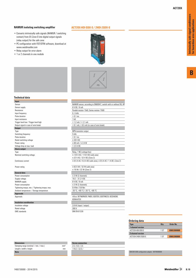
NAMUR isolating switching amplifier
• Converts intrinsically safe signals (NAMUR / switching contact) from EX Zone 0 into digital output signals (relay output) for the safe zone
• PC configuration with FDT/DTM software, download at www.weidmueller.com
• Relay output for error alarm• 1 or 2 channels in one module
Technical dataInputSensorSensor supplyResistanceInput frequencyPulse durationInput resistanceTrigger level low / Trigger level highOutput signal in case of wire breakOutputType Switching frequencyPulse duration Rated switching voltagePower ratingVoltage drop at max. loadAlarm outputType Nominal switching voltage
Continuous current
Power rating
General dataPower consumptionSupply voltageNAMUR supplyPower consumptionTightening torque, min. / Tightening torque, max.Ambient temperature / Storage temperatureApprovalsApprovals
Insulation coordinationInsulation voltageRated voltageEMC standards
DimensionsClamping range (nominal / min. / max.) mm²Length x width x height mmNote
ACT20X-HDI-SDO-S / 2HDI-2SDO-S
PS
NAMUR sensor, according to EN60947, switch with or without RS, RP8 V DC / 8 mAParallel resistor 15kΩ, Series resistor 750Ω0...5 kHz> 0.1 ms1 kΩ< 1.2 mA / > 2.1 mA< 0.1 mA, > 6.5 mA (in case of wire break)
NPN transistor output5 kHz> 0.1 ms≤ 30 V DC≤ 80 mA / ≤ 2.4 W< 2.5 V DC
Relay, 1 NC (voltage-free)≤ 125 V AC / 110 V DC (safe area) ≤ 32 V AC / 32 V DC (Zone 2)≤ 0.5 A AC / 0.3 A DC (safe zone), ≤ 0.5 A AC / 1 A DC ( Zone 2)
≤ 62.5 VA / 32 W (safe area) ≤ 16 VA / 32 W (Zone 2)
≤ 3 W (2 channels)19.2 – 31.2 V DC8 V DC / 8 mA≤ 3 W (2 channels)0.4 Nm / 0.6 Nm-20 °C...+60 °C / -20 °C...+85 °C
cULus; DETNORVER; FMEX; GOSTEX; GOSTME25; IECEXKEM; KEMAATEX
2.6 kV (input / output)300 VDIN EN 61326
Type Qty. Order No.1-channel versionACT20X-HDI-SDO-S 1 ST 89653600002-channel versionACT20X-2HDI-2SDO-S 1 ST 8965390000
CBX200 USB configuration adapter - 8978580000
Ordering data
Screw connection2.5 / 0.5 / 2.5119.2 / 22.5 /
Intri
nsica
lly sa
fe si
gnal
cond
ition
ers
for h
azar
dous
area
appli
catio
ns
ACT20X
ACT20X
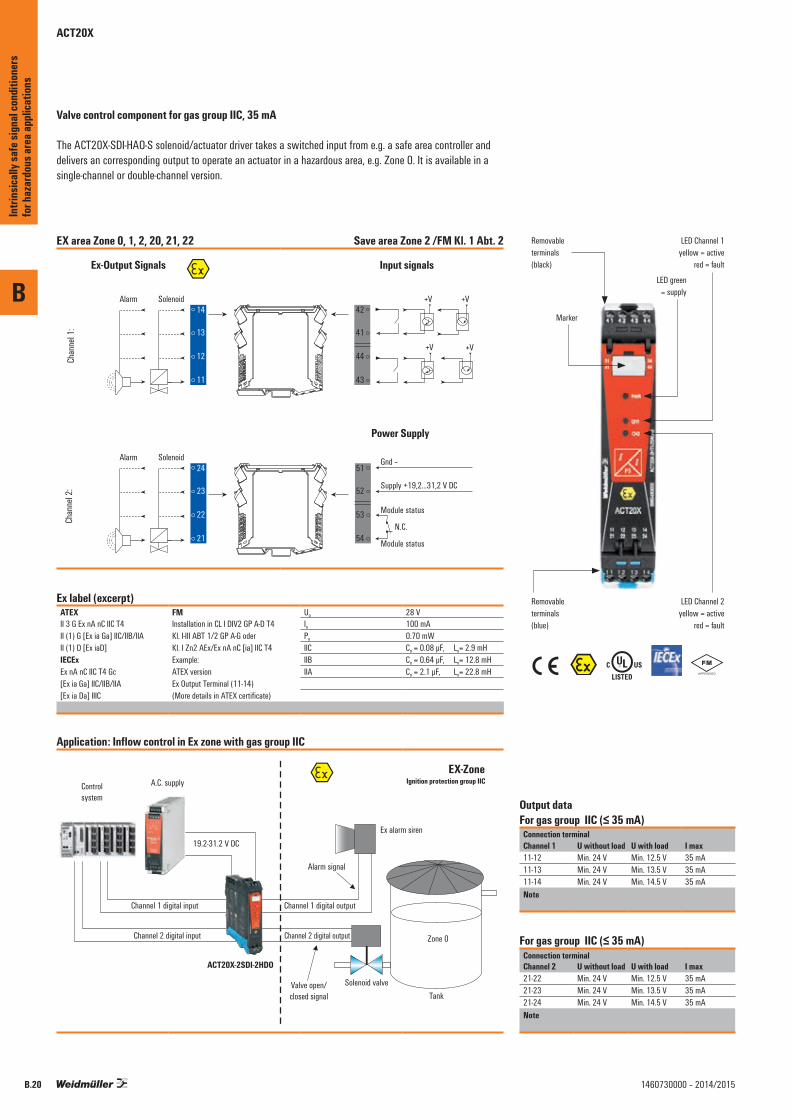
Valve control component for gas group IIC, 35 mA
The ACT20X-SDI-HAO-S solenoid/actuator driver takes a switched input from e.g. a safe area controller and delivers an corresponding output to operate an actuator in a hazardous area, e.g. Zone 0. It is available in a single-channel or double-channel version.
EX area Zone 0, 1, 2, 20, 21, 22 Save area Zone 2 /FM Kl. 1 Abt. 2
Chan
nel 1
:Ch
anne
l 2:
51
52
53
54
Ex-Output Signals
44
43
42
41
14
13
12
11
24
23
22
21
Input signals
Gnd –
Supply +19,2...31,2 V DC
Module status
Module status
42
41
44
43
N.C.
Power Supply
Alarm Solenoid V+V+
V+V+
Alarm Solenoid
Ex label (excerpt)ATEX FM Uo 28 VII 3 G Ex nA nC IIC T4 Installation in CL I DIV2 GP A-D T4
Kl. I-III ABT 1/2 GP A-G oder Kl. I Zn2 AEx/Ex nA nC [ia] IIC T4
Io 100 mAII (1) G [Ex ia Ga] IIC/IIB/IIA Po 0.70 mWII (1) D [Ex iaD] IIC Co = 0.08 µF, Lo= 2.9 mHIECEx Example: IIB Co = 0.64 µF, Lo= 12.8 mHEx nA nC IIC T4 Gc ATEX version IIA Co = 2.1 µF, Lo= 22.8 mH[Ex ia Ga] IIC/IIB/IIA Ex Output Terminal (11-14)[Ex ia Da] IIIC (More details in ATEX certificate)
Application: Inflow control in Ex zone with gas group IIC
Controlsystem
A.C. supply Ignition protection group IIC
ACT20X-2SDI-2HDO
19.2-31.2 V DC
Channel 1 digital input
Channel 2 digital input
Alarm signal
Valve open/closed signal
Solenoid valve
Ex alarm siren
Tank
Zone 0
Channel 1 digital output
Channel 2 digital output
EX-Zone
\%
Output data For gas group IIC (≤ 35 mA)
Connection terminalChannel 1 U without load U with load I max11-12 Min. 24 V Min. 12.5 V 35 mA11-13 Min. 24 V Min. 13.5 V 35 mA11-14 Min. 24 V Min. 14.5 V 35 mANote
For gas group IIC (≤ 35 mA)Connection terminalChannel 2 U without load U with load I max21-22 Min. 24 V Min. 12.5 V 35 mA21-23 Min. 24 V Min. 13.5 V 35 mA21-24 Min. 24 V Min. 14.5 V 35 mANote
Removableterminals(black)
LED green= supply
Marker
Removableterminals(blue)
LED Channel 2yellow = active
red = fault
LED Channel 1yellow = active
red = fault
B
Intri
nsica
lly sa
fe si
gnal
cond
ition
ers
for h
azar
dous
area
appli
catio
ns
B.20 1460730000 – 2014/2015
B
B.211460730000 – 2014/2015
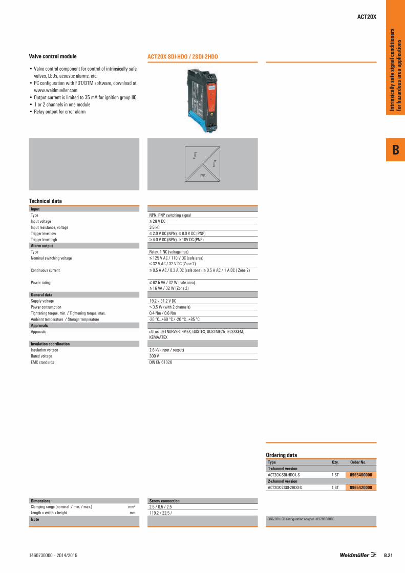
Valve control module
• Valve control component for control of intrinsically safe valves, LEDs, acoustic alarms, etc.
• PC configuration with FDT/DTM software, download at www.weidmueller.com
• Output current is limited to 35 mA for ignition group IIC• 1 or 2 channels in one module• Relay output for error alarm
Technical dataInputTypeInput voltageInput resistance, voltageTrigger level lowTrigger level highAlarm outputType Nominal switching voltage
Continuous current
Power rating
General dataSupply voltagePower consumptionTightening torque, min. / Tightening torque, max.Ambient temperature / Storage temperatureApprovalsApprovals
Insulation coordinationInsulation voltageRated voltageEMC standards
DimensionsClamping range (nominal / min. / max.) mm²Length x width x height mmNote
ACT20X-SDI-HDO / 2SDI-2HDO
PS
NPN, PNP switching signal≤ 28 V DC3.5 kΩ≤ 2.0 V DC (NPN), ≤ 8.0 V DC (PNP)≥ 4.0 V DC (NPN), ≥ 10V DC (PNP)
Relay, 1 NC (voltage-free)≤ 125 V AC / 110 V DC (safe area) ≤ 32 V AC / 32 V DC (Zone 2)≤ 0.5 A AC / 0.3 A DC (safe zone), ≤ 0.5 A AC / 1 A DC ( Zone 2)
≤ 62.5 VA / 32 W (safe area) ≤ 16 VA / 32 W (Zone 2)
19.2 – 31.2 V DC≤ 3.5 W (with 2 channels)0.4 Nm / 0.6 Nm-20 °C...+60 °C / -20 °C...+85 °C
cULus; DETNORVER; FMEX; GOSTEX; GOSTME25; IECEXKEM; KEMAATEX
2.6 kV (input / output)300 VDIN EN 61326
Type Qty. Order No.1-channel versionACT20X-SDI-HDO-L-S 1 ST 89654000002-channel versionACT20X-2SDI-2HDO-S 1 ST 8965420000
CBX200 USB configuration adapter - 8978580000
Ordering data
Screw connection2.5 / 0.5 / 2.5119.2 / 22.5 /
Intri
nsica
lly sa
fe si
gnal
cond
ition
ers
for h
azar
dous
area
appli
catio
ns
ACT20X
ACT20X
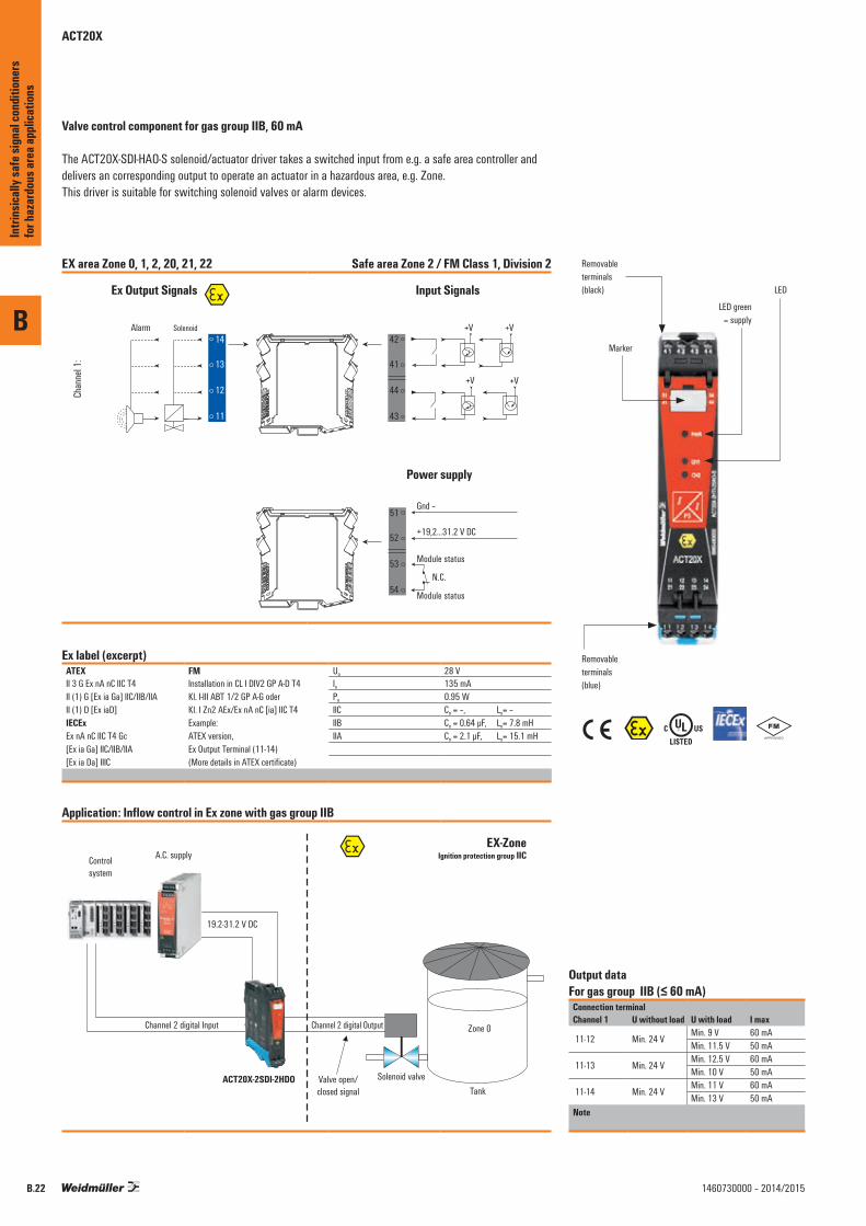
Valve control component for gas group IIB, 60 mA
The ACT20X-SDI-HAO-S solenoid/actuator driver takes a switched input from e.g. a safe area controller and delivers an corresponding output to operate an actuator in a hazardous area, e.g. Zone. This driver is suitable for switching solenoid valves or alarm devices.
EX area Zone 0, 1, 2, 20, 21, 22 Safe area Zone 2 / FM Class 1, Division 2
Chan
nel 1
:
51
52
53
54
Ex Output Signals
44
43
42
41
14
13
12
11
Input Signals
Gnd –
+19,2...31.2 V DC
Module status
Module status
42
41
44
43
N.C.
Power supply
Alarm Solenoid V+V+
V+V+
Ex label (excerpt)ATEX FM Uo 28 VII 3 G Ex nA nC IIC T4 Installation in CL I DIV2 GP A-D T4
Kl. I-III ABT 1/2 GP A-G oder Kl. I Zn2 AEx/Ex nA nC [ia] IIC T4
Io 135 mAII (1) G [Ex ia Ga] IIC/IIB/IIA Po 0.95 WII (1) D [Ex iaD] IIC Co = –, Lo= –IECEx Example: IIB Co = 0.64 µF, Lo= 7.8 mHEx nA nC IIC T4 Gc ATEX version, IIA Co = 2.1 µF, Lo= 15.1 mH[Ex ia Ga] IIC/IIB/IIA Ex Output Terminal (11-14)[Ex ia Da] IIIC (More details in ATEX certificate)
Application: Inflow control in Ex zone with gas group IIB
Controlsystem
A.C. supply Ignition protection group IIC
ACT20X-2SDI-2HDO
19.2-31.2 V DC
Channel 2 digital Input
Valve open/closed signal
Solenoid valveTank
Zone 0Channel 2 digital Output
EX-Zone
\%
Output data For gas group IIB (≤ 60 mA)
Connection terminalChannel 1 U without load U with load I max
11-12 Min. 24 VMin. 9 V 60 mAMin. 11.5 V 50 mA
11-13 Min. 24 VMin. 12.5 V 60 mAMin. 10 V 50 mA
11-14 Min. 24 VMin. 11 V 60 mAMin. 13 V 50 mA
Note
Removableterminals(black)
LED green= supply
Marker
Removableterminals(blue)
LED
B
Intri
nsica
lly sa
fe si
gnal
cond
ition
ers
for h
azar
dous
area
appli
catio
ns
B.22 1460730000 – 2014/2015
B
B.231460730000 – 2014/2015
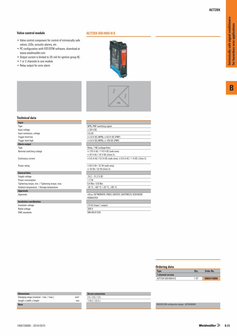
Valve control module
• Valve control component for control of intrinsically safe valves, LEDs, acoustic alarms, etc.
• PC configuration with FDT/DTM software, download at www.weidmueller.com
• Output current is limited to 35 mA for ignition group IIC• 1 or 2 channels in one module• Relay output for error alarm
Technical dataInputTypeInput voltageInput resistance, voltageTrigger level lowTrigger level highAlarm outputType Nominal switching voltage
Continuous current
Power rating
General dataSupply voltagePower consumptionTightening torque, min. / Tightening torque, max.Ambient temperature / Storage temperatureApprovalsApprovals
Insulation coordinationInsulation voltageRated voltageEMC standards
DimensionsClamping range (nominal / min. / max.) mm²Length x width x height mmNote
ACT20X-SDI-HDO-H-S
PS
NPN, PNP switching signal≤ 28 V DC3.5 kΩ≤ 2.0 V DC (NPN), ≤ 8.0 V DC (PNP)≥ 4.0 V DC (NPN), ≥ 10V DC (PNP)
Relay, 1 NC (voltage-free)≤ 125 V AC / 110 V DC (safe area) ≤ 32 V AC / 32 V DC (Zone 2)≤ 0.5 A AC / 0.3 A DC (safe zone), ≤ 0.5 A AC / 1 A DC ( Zone 2)
≤ 62.5 VA / 32 W (safe area) ≤ 16 VA / 32 W (Zone 2)
19.2 – 31.2 V DC< 2 W0.4 Nm / 0.6 Nm-20 °C...+60 °C / -20 °C...+85 °C
cULus; DETNORVER; FMEX; GOSTEX; GOSTME25; IECEXKEM; KEMAATEX
2.6 kV (input / output)300 VDIN EN 61326
Type Qty. Order No.1-channel versionACT20X-SDI-HDO-H-S 1 ST 8965410000
CBX200 USB configuration adapter - 8978580000
Ordering data
Screw connection2.5 / 0.5 / 2.5119.2 / 22.5 /
Intri
nsica
lly sa
fe si
gnal
cond
ition
ers
for h
azar
dous
area
appli
catio
ns
ACT20X

B
Intri
nsica
lly sa
fe si
gnal
cond
ition
ers
for h
azar
dous
area
appli
catio
ns
B.24 1460730000 – 2014/2015
Recommended


![INDEX [exceltecinc.com] · Signal Conditioners Tutorial 6 A quick overview for signal conditioners. SC-FI 7 Frequency to current signal conditioner. SC-II 9 Current to current isolator](https://img.pdfslide.us/doc/110x75/5f63f0b95c835b58a2452785/index-signal-conditioners-tutorial-6-a-quick-overview-for-signal-conditioners.jpg)