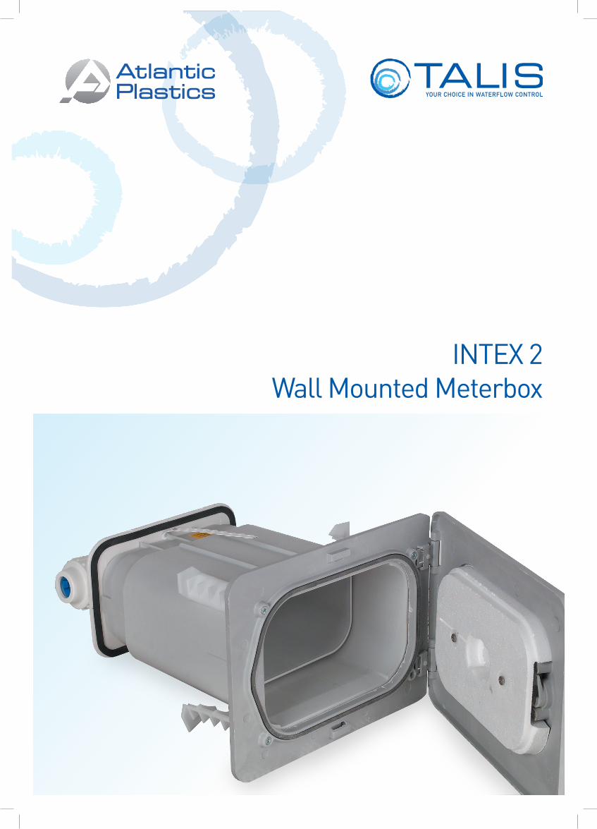
INTEX 2Wall Mounted Meterbox
INTEX 2 Wall Mounted Meter Box
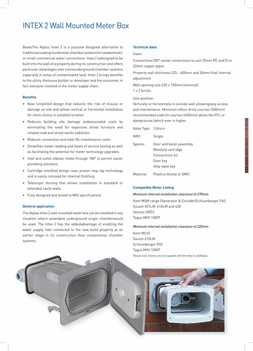
BoxesThe Atplas Intex 2 is a purpose designed alternative to traditional underground meter chamber systems for newdomestic or small commercial water connections. Intex 2 isdesigned to be built into the wall of a property during its construction and offers particular advantages over someunderground chamber systems especially in areas of contaminated land. Intex 2 brings benefits to the utility, thehouse builder or developer and the consumer, in fact everyone involved in the meter supply chain.
Benefits
• New simplified design that reduces the risk of misuse or damage on site and allows vertical or horizontal installation for more choice in installed location
• Reduces building site damage andassociated costs by eliminating the need for expensive street furniture and relatedroadandstreetworksliabilities
• Reducesconnectionandtotallifemaintenancecosts
• Simplifiesmeterreadingandlevelsofservicetestingaswell as facilitating the potential for meter technology upgrades
• Inletandoutletelbowsrotatethrough180°topermiteasier plumbing solutions
• Cartridgemanifolddesignusesprovenstop tap technology and is easily removed for internal finishing
• Telescopic ducting that allows installation in standard or extended cavity walls
• FullydesignedandtestedtoWISspecifications
General application
The Atplas Intex 2 wall mounted meter box can be installed in any situation where astandard underground single chamberwould be used. The Intex 2 has the addedadvantage of enabling the water supply tobe connected to the new build property at an earlier stage in its construction than conventional chamber systems.
Technical data:
Sizes:
Connections180°swivelconnectionstosuit25mmPEand15or22mm copper pipes
Propertywallthickness:225-400mmand30mmfinalinternaladjustment
Wallopeningsize:230x150mm(nominal) 1x2bricks
Unitposition: Vertically or horizontally in outside wall allowingeasy access andmaintenance.Minimumoffourbrickcourses(300mm)recommendedsixbrickcourses(450mm)abovetheFFLordampcourse(whicheverishigher
ValveType: 1/4turn
NRV: Single
Spares: Doorandbezelassembly Manifold cartridge Connectionskit Doorkey Stopvalvekey
Material: Plastics:AcetalorDMC
Compatible Meter Listing
Minimum internal installation clearance of 270mm
KentMSMrange(Generator&Encoder)SchlumbergerP40 Socam501LM,610LMand630 SensusSRD3 TagusMVV1000T
Minimum internal installation clearance of 225mm
KentMS10 Socam610LM SchlumbergerP40 TagusMVV1000T Pleasenote,metersarenotsuppliedwiththeIntexllunitAtplas
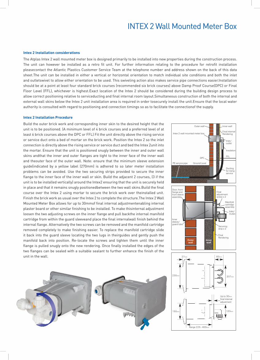
Intex 2 Installation considerations
The Atplas Intex 2 wall mounted meter box is designed primarily to be installed into new properties during the construction process.The unit can however be installed as a retro fit unit. For further information relating to the procedure for retrofit installationpleasecontacttheAtlanticPlasticsCustomerServiceTeamatthetelephonenumberandaddressshownonthebackofthisdatasheet.The unit can be installed in either a vertical or horizontal orientation to match individual site conditions and both the inlet andoutletswiveltoalloweitherorientationtobeused.Thisswivelingactionalsomakesservicepipeconnectionseasier.Installationshouldbeatapointatleastfourstandardbrickcourses(recommendedsixbrickcourses)aboveDampProofCourse(DPC)orFinalFloorLevel (FFL),whichever ishighest.Exact locationof the Intex2 shouldbeconsideredduring thebuildingdesignprocess toallowcorrectpositioningrelativetoserviceductingandfinalinternalroomlayout.SimultaneousconstructionofboththeinternalandexternalwallskinsbelowtheIntex2unitinstallationareaisrequiredinordertosecurelyinstalltheunit.Ensurethatthelocalwaterauthority is consulted with regard to positioning and connection timings so as to facilitate the connectionof the supply.
Intex 2 Installation Procedure
Buildtheouterbrickworkandcorrespondinginnerskintothedesiredheightthattheunitistobepositioned.(Aminimumlevelof4brickcoursesandapreferredlevelofatleast6brickcoursesabovetheDPCorFFL)Fittheunitdirectlyabovetherisingserviceorserviceductontoabedofmortaronthebrickwork.PositiontheIntex2sotheinletconnection is directly above the rising service or service duct and bed the Intex 2unit into the mortar. Ensure that the unit is positioned snugly between the inner and outer wall skinsandthattheinnerandouterflangesaretighttotheinnerfaceoftheinnerwallandtheouterfaceoftheouterwall.Note:ensurethattheminimumsleeveextensionguide(indicated by a yellow label (270mm) is adhered to so latermeter installationproblems can be avoided. Use the two securing strips provided to secure the inner flangetotheinnerfaceoftheinnerwallorskin.Buildtheadjacent2courses,(3iftheunitistobeinstalledvertically)aroundtheIntex2ensuringthattheunitissecurelyheldinplaceandthatitremainssnuglypositionedbetweenthetwowallskins.Buildthefinalcourseover the Intex2usingmortar tosecurethebrickworkover theinstalledunit.FinishthebrickworkasusualovertheIntex2tocompletethestructure.TheIntex2WallMountedMeterBoxallowsforupto30mmoffinalinternaladjustmentenablinginternalplasterboardorothersimilarfinishingtobeinstalled.Tomakethisinternaladjustmentloosenthetwoadjustingscrewsontheinnerflangeandpullbacktheinternalmanifoldcartridge from within the guard sleeveand place the final internalwall finish behind the internalflange.Alternativelythetwoscrewscanberemovedandthemanifoldcartridgeremovedcompletely tomakefinishingeasier.Toreplacethemanifoldcartridgeslideitbackintotheguardsleevelocatingthetwolugsintheirguidesandgentlypushthemanifold back into position. Re-locate the screws and tighten them until the innerflangeispulledsnuglyontothenewrendering.Oncefinallyinstalledtheedgesofthetwoflangescanbesealedwithasuitablesealanttofurtherenhancethefinishoftheunit in the wall.
The Atplas Intex 2 wall mounted meter box is designed primarily to be installed into new properties during the construction process.The unit can however be installed as a retro fit unit. For further information relating to the procedure for retrofit installation pleasecontact the Atlantic Plastics Customer Service Team at the telephone number and address shown on the back of this data sheet.
The unit can be installed in either a vertical or horizontal orientation to match individual site conditions and both the inlet and outletswivel to allow either orientation to be used. This swiveling action also makes service pipe connections easier.
Installation should be at a point at least four standard brick courses (recommended six brick courses) above Damp Proof Course(DPC) or Final Floor Level (FFL), whichever is highest.
Exact location of the Intex 2 should be considered during the building design process to allow correct positioning relative to serviceducting and final internal room layout.
Simultaneous construction of both the internal and external wall skins below the Intex 2 unit installation area is required in order tosecurely install the unit.
Ensure that the local water authority is consulted with regard to positioning and connection timings so as to facilitate the connectionof the supply.
Build the outer brick work and corresponding inner skin to the desired height that theunit is to be positioned. (A minimum level of 4 brick courses and a preferred level of atleast 6 brick courses above the DPC or FFL)
Fit the unit directly above the rising service or service duct onto a bed of mortar on thebrick work. Position the Intex 2 so the inlet connection is directly above the rising service or service duct and bed the Intex 2 unit into the mortar.
Ensure that the unit is positioned snugly between the inner and outer wall skins andthat the inner and outer flanges are tight to the inner face of the inner wall and theouter face of the outer wall. Note: ensure that the minimum sleeve extension guide(indicated by a yellow label (270mm) is adhered to so later meter installation problems can be avoided. Use the two securing strips provided to secure the innerflange to the inner face of the inner wall or skin.
Build the adjacent 2 courses, (3 if the unit is to be installed vertically) around the Intex2 ensuring that the unit is securely held in place and that it remains snugly positionedbetween the two wall skins.
Build the final course over the Intex 2 using mortar to secure the brick work over theinstalled unit. Finish the brick work as usual over the Intex 2 to complete the structure.
The Intex 2 Wall Mounted Meter Box allows for up to 30mm of final internal adjustmentenabling internal plaster board or other similar finishing to be installed. To make thisinternal adjustment loosen the two adjusting screws on the inner flange and pull backthe internal manifold cartridge from within the guard sleeve and place the final internalwall finish behind the internal flange. Alternatively the two screws can be removedand the manifold cartridge removed completely to make finishing easier. To replacethe manifold cartridge slide it back into the guard sleeve locating the two lugs in theirguides and gently push the manifold back into position. Re-locate the screws andtighten them until the inner flange is pulled snugly onto the new rendering.
Once finally installed the edges of the two flanges can be sealed with a suitablesealant to further enhance the finish of the unit in the wall.
Intex 2 Installation Procedure
Intex 2 Installation considerations
Wall Mounted Meter Box
Wall Mounted Meter Box
Ground LevelPE service pipe
DPC
Ductingfor risingservice
Outer wall
Innerwall
FinalRendering
Securingstrip x 2
Inlet/Outlet
Finaladjustmentscrew x 2
Manifoldcartridgeassembly
Door, frontflange andfront sleeveassembly
Innersleeve/guard tube
Outer wall Inner wall
Final internalRendering
Inlet/outlet
Insulation
FFL
Intex 2 wall mounted meter box
Range 225 - 400mm
Up to 30mm
final internaladjustment
207mm
83mm27mm
230mm
120mm150mm
2
Swiveling inletand outlet
Atplas INTEX 2 Wall Mounted Meter Box mk3.qxp 18/06/2007 14:50 Page 2
INTEX 2 Wall Mounted Meter Box
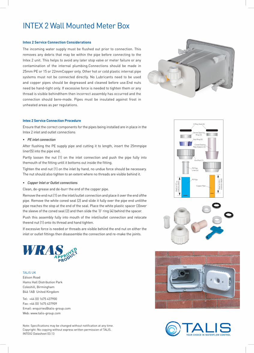
Intex 2 Service Connection Considerations
The incomingwatersupplymustbeflushedoutpriortoconnection.Thisremoves any debris that may be within the pipe before connecting to the Intex 2 unit. This helps to avoid any later stop valve or meter failure or any contamination of the internal plumbing.Connections should be made in25mmPEor15or22mmCopperonly.Otherhotorcoldplasticinternalpipesystemsmust not be connected directly.NoLubricants need to be usedand copper pipes should be degreased and cleaned before use.End nuts needbehand-tightonly.Ifexcessiveforceisneededtotightenthemoranythread is visible behindthem then incorrect assembly has occurred and the connection should bere-made. Pipes must be insulated against frost inunheated areas as per regulations.
INTEX 2 Wall Mounted Meter Box
Intex 2 Service Connection Procedure
Ensure that the correct components for the pipes being installed are in place in the Intex 2 inlet and outlet connections
• PEinletconnection
Afterflushing thePEsupplypipeandcutting it to length, insert the25mmpipeliner(5)intothepipeend.
Partly loosen the nut (1) on the inlet connection and push the pipe fully intothemouth of the fitting until it bottoms out inside the fitting.
Tightentheendnut(1)ontheinletbyhand,noundueforceshouldbenecessary.The nut should also tighten to an extent where no threads are visible behind it.
• CopperInletorOutletconnections
Clean,de-greaseandde-burrtheendofthecopperpipe.
Removetheendnut(1)ontheinlet/outletconnectionandplaceitovertheendofthepipe.Removethewhiteconedseal(2)andslideitfullyoverthepipeenduntilthepipereachesthestopattheendoftheseal.Placethewhiteplasticspacer(3)overthesleeveoftheconedseal(2)andthenslidethe‘O’ring(4)behindthespacer.
Push this assembly fully intomouthof the inlet/outlet connectionand relocatetheendnut(1)ontoitsthreadandhandtighten.
If excessive force is needed or threads are visible behind the end nut on either the inletoroutletfittingsthendisassembletheconnectionandre-makethejoints.
Intex 2 Service Connection Procedure
Wall Mounted Meter Box
Wall Mounted Meter Box
Ensure that the correct components for the pipes being installed are in place in theIntex 2 inlet and outlet connections
� PE inlet connection
After flushing the PE supply pipe and cutting it to length, insert the 25mm pipe liner(5) into the pipe end.
Partly loosen the nut (1) on the inlet connection and push the pipe fully into themouth of the fitting until it bottoms out inside the fitting.
Tighten the end nut (1) on the inlet by hand, no undue force should be necessary.The nut should also tighten to an extent where no threads are visible behind it.
� Copper Inlet or Outlet connections
Clean, de-grease and de-burr the end of the copper pipe.
Remove the end nut (1) on the inlet/outlet connection and place it over the end ofthe pipe. Remove the white coned seal (2) and slide it fully over the pipe end untilthe pipe reaches the stop at the end of the seal. Place the white plastic spacer (3)over the sleeve of the coned seal (2) and then slide the ‘O’ ring (4) behind the spacer.
Push this assembly fully into mouth of the inlet/outlet connection and relocate theend nut (1) onto its thread and hand tighten.
If excessive force is needed or threads are visible behind the end nut on either theinlet or outlet fittings then disassemble the connection and re-make the joints.
Intex 2 Service Connection Considerations
The incoming water supply must beflushed out prior to connection. Thisremoves any debris that may be withinthe pipe before connecting to the Intex2 unit. This helps to avoid any laterstop valve or meter failure or any contamination of the internal plumbing.
Connections should be made in 25mm
PE or 15 or 22mm Copper only. Otherhot or cold plastic internal pipe systemsmust not be connected directly.
No Lubricants need to be used and copper pipes should be degreased andcleaned before use.
End nuts need be hand-tight only. Ifexcessive force is needed to tightenthem or any thread is visible behindthem then incorrect assembly hasoccurred and the connection should bere-made.
Pipes must be insulated against frost inunheated areas as per regulations.
O Ring Seal (4)
Centre SpacingRing (3)
Grip Ring (6)
Coned SealingPipe Adaptor (2)
End Nut (1)
PE Pipe
PE PipeLiner (5)
Mar
k fo
r 67
mm
inse
rtio
n de
pth
Copper Pipe
3
Mar
k fo
r 65
mm
inse
rtio
n de
pth
Atplas INTEX 2 Wall Mounted Meter Box mk3.qxp 18/06/2007 14:51 Page 3
Note:Specificationsmaybechangedwithoutnotificationatanytime.Copyright:NocopyingwithoutexpresswrittenpermissionofTALIS.INTEX2Datasheet03.13
TALISUK EdisonRoad HamsHallDistributionPark Coleshill,Birmingham B461ABUnitedKingdom
Tel:+44(0)1675437900 Fax:+44(0)1675437909 Email:[email protected] Web:www.talis-group.com
Recommended