1/26
Information on available spare parts:
www.boschrexroth.com/spc
Internal gear pump,
fixed displacement
Type PGH
Frame sizes 2, 3, 4 and 5Component series: 2XMaximum operating pressure 350 barMaximum displacement 250 cm3
RE 10223/10.05Replaces: 03.05
Double pump type PGH4 + PGH3Type PGH… with SAE 2-hole mount-
ing flange
H7148H7172
Table of contents
Contents Page
Features 1
Ordering code 2
Function, section, symbol 3
Technical data 4 and 5
Characteristic curves 6 to 11
Unit dimensions 12 to 17
Multiple pumps 18 to 22
SAE connecting flanges 23
Installation notes 24
Commissioning notes 25
Engineering notes 26
Features
– Fixed displacement
– Low operating noise
– Low flow pulsation
– High efficiency even at low speed and viscosity due to sealing
gap compensation
– Suitable for wide viscosity and speed ranges
– All frame sizes and nominal sizes can freely combined with
each other
– Can be combined with PGF internal gear pumps, vane pumps
and axial piston pumps
– Suitable for operation with HFC fluids
(seal version “W“)
2/26 Bosch Rexroth AG Hydraulics PGH RE 10223/10.05
Ordering code
Series
High pressure pump = H
Frame size
FS2 = 2
FS3 = 3
FS4 = 4
FS5 = 5
Component series: Component series 20 to 29 = 2X
(20 to 29: unchanged installation and
connection dimensions)
Size
Size
Displacement/
revolution
FS2 5.0
6.3
8.0
5.2 cm3
6.5 cm3
8.2 cm3
= 005
= 006
= 008
FS3 11
13
16
11.0 cm3
13.3 cm3
16.0 cm3
= 011
= 013
= 016
FS4 20
25
32
40
50
63
80
100
20.10 cm3
25.30 cm3
32.70 cm3
40.10 cm3
50.70 cm3
65.50 cm3
80.30 cm3
101.40 cm3
= 020
= 025
= 032
= 040
= 050
= 063
= 080
= 100
FS5 63
80
100
125
160
200
250
64.70 cm3
81.40 cm3
100.20 cm3
125.30 cm3
162.80 cm3
200.40 cm3
250.50 cm3
= 063
= 080
= 100
= 125
= 160
= 200
= 250
Further details in clear text
Mounting flange centring
U2 = SAE 2-hole mounting flange
E4 = 1) ISO 4-hole mounting flange to
ISO 3019/2 and
VDMA 24560 part 1
Seal material
V = FKM seals
W = 2) Shaft seal ring made of NBR
(other seals made of FKM)
Suction and pressure port to SAE 3)
07 = Pressure port for standard pressure series
11 = Pressure port for high pressure series
Shaft version
E = Cylindrical
R = SAE involute splined shaft
Direction of rotation (viewed to shaft end)
R = Clockwise
L = Counter-clockwise
PG H 2X *
Order example: PGH4-2X/032RE11VU2
Material number: R900932141
Not all variants according to the type code are possible!
Please select the desired pump on the basis of the selec-
tion table (pages 12 to 17) or consult Bosch Rexroth.
1) Only in conjunction with cylindrical shaft (to VDMA),
frame sizes 4 and 5 only, clockwise rotation only
2) FS4 and FS5 only for operation with HFC fluid
3) A type of connection 07 or 11 is determined for each size:
07: PGH2-2X/005/006/008…
PGH3-2X/011/013/016…
PGH4-2X/063/080/100…
PGH5-2X/160/200/250…
11: PGH4-2X/020/025/032/040/050…
PGH5-2X/063/080/100/125…
The suction ports are standard pressure series ports (for the
dimensions, see page 17).
P
S
2
11
8
5 454
61.2 1.1 1.273
FR
9.2
9.19.3 9
P
S
FA
10
5
FA
10
5
Hydraulics Bosch Rexroth AGRE 10223/10.05 PGH 3/26
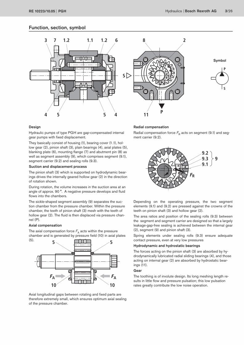
Function, section, symbol
Symbol
Design
Hydraulic pumps of type PGH are gap-compensated internal
gear pumps with fixed displacement.
They basically consist of housing (1), bearing cover (1.1), hol-
low gear (2), pinion shaft (3), plain bearings (4), axial plates (5),
blanking plate (6), mounting fl ange (7) and abutment pin (8) as
well as segment assembly (9), which comprises segment (9.1),
segment carrier (9.2) and sealing rolls (9.3).
Suction and displacement process
The pinion shaft (3) which is supported on hydrodynamic bear-
ings drives the internally geared hollow gear (2) in the direction
of rotation shown.
During rotation, the volume increases in the suction area at an
angle of approx. 90 °. A negative pressure develops and fl uid
fl ows into the chambers.
The sickle-shaped segment assembly (9) separates the suc-
tion chamber from the pressure chamber. Within the pressure
chamber, the teeth of pinion shaft (3) mesh with the teeth of
hollow gear (2). The fl uid is then displaced via pressure chan-
nel (P).
Axial compensation
The axial compensation force FA acts within the pressure
chamber and is generated by pressure field (10) in axial plates
(5).
Radial compensation
Radial compensation force FR acts on segment (9.1) and seg-
ment carrier (9.2).
Depending on the operating pressure, the two segment
elements (9.1) and (9.2) are pressed against the crowns of the
teeth on pinion shaft (3) and hollow gear (2).
The area ratios and position of the sealing rolls (9.3) between
the segment and segment carrier are designed so that a largely
leakage-gap-free sealing is achieved between the internal gear
(2), segment (9) and pinion shaft (3).
Spring elements under sealing rolls (9.3) ensure adequate
contact pressure, even at very low pressures
Hydrodynamic and hydrostatic bearings
The forces acting on the pinion shaft (3) are absorbed by hy-
drodynamically lubricated radial sliding bearings (4), and those
acting on internal gear (2) are absorbed by hydrostatic bear-
ings (11).
Gear
The toothing is of involute design. Its long meshing length re-
sults in little flow and pressure pulsation; this low pulsation
rates greatly contribute the low noise operation.
Axial longitudinal gaps between rotating and fi xed parts are
therefore extremely small, which ensures optimum axial sealing
of the pressure chamber.
4/26 Bosch Rexroth AG Hydraulics PGH RE 10223/10.05
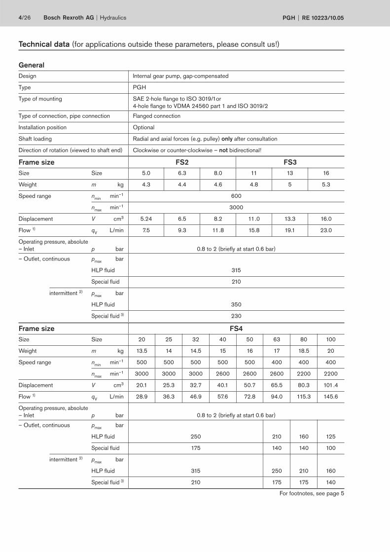
Technical data (for applications outside these parameters, please consult us!)
General
Design Internal gear pump, gap-compensated
Type PGH
Type of mounting SAE 2-hole flange to ISO 3019/1or
4-hole flange to VDMA 24560 part 1 and ISO 3019/2
Type of connection, pipe connection Flanged connection
Installation position Optional
Shaft loading Radial and axial forces (e.g. pulley) only after consultation
Direction of rotation (viewed to shaft end) Clockwise or counter-clockwise – not bidirectional!
Frame size FS2 FS3
Size Size 5.0 6.3 8.0 11 13 16
Weight m kg 4.3 4.4 4.6 4.8 5 5.3
Speed range nmin
min–1 600
nmax
min–1 3000
Displacement V cm3 5.24 6.5 8.2 11.0 13.3 16.0
Flow 1) qV
L/min 7.5 9.3 11.8 15.8 19.1 23.0
Operating pressure, absolute
– Inlet p bar 0.8 to 2 (briefly at start 0.6 bar)
– Outlet, continuous pmax
bar
HLP fluid 315
Special fluid 210
intermittent 2) pmax
bar
HLP fluid 350
Special fluid 3) 230
For footnotes, see page 5
Frame size FS4
Size Size 20 25 32 40 50 63 80 100
Weight m kg 13.5 14 14.5 15 16 17 18.5 20
Speed range nmin
min–1 500 500 500 500 500 400 400 400
nmax
min–1 3000 3000 3000 2600 2600 2600 2200 2200
Displacement V cm3 20.1 25.3 32.7 40.1 50.7 65.5 80.3 101.4
Flow 1) qV
L/min 28.9 36.3 46.9 57.6 72.8 94.0 115.3 145.6
Operating pressure, absolute
– Inlet p bar 0.8 to 2 (briefly at start 0.6 bar)
– Outlet, continuous pmax
bar
HLP fluid 250 210 160 125
Special fluid 175 140 140 100
intermittent 2) pmax
bar
HLP fluid 315 250 210 160
Special fluid 3) 210 175 175 140
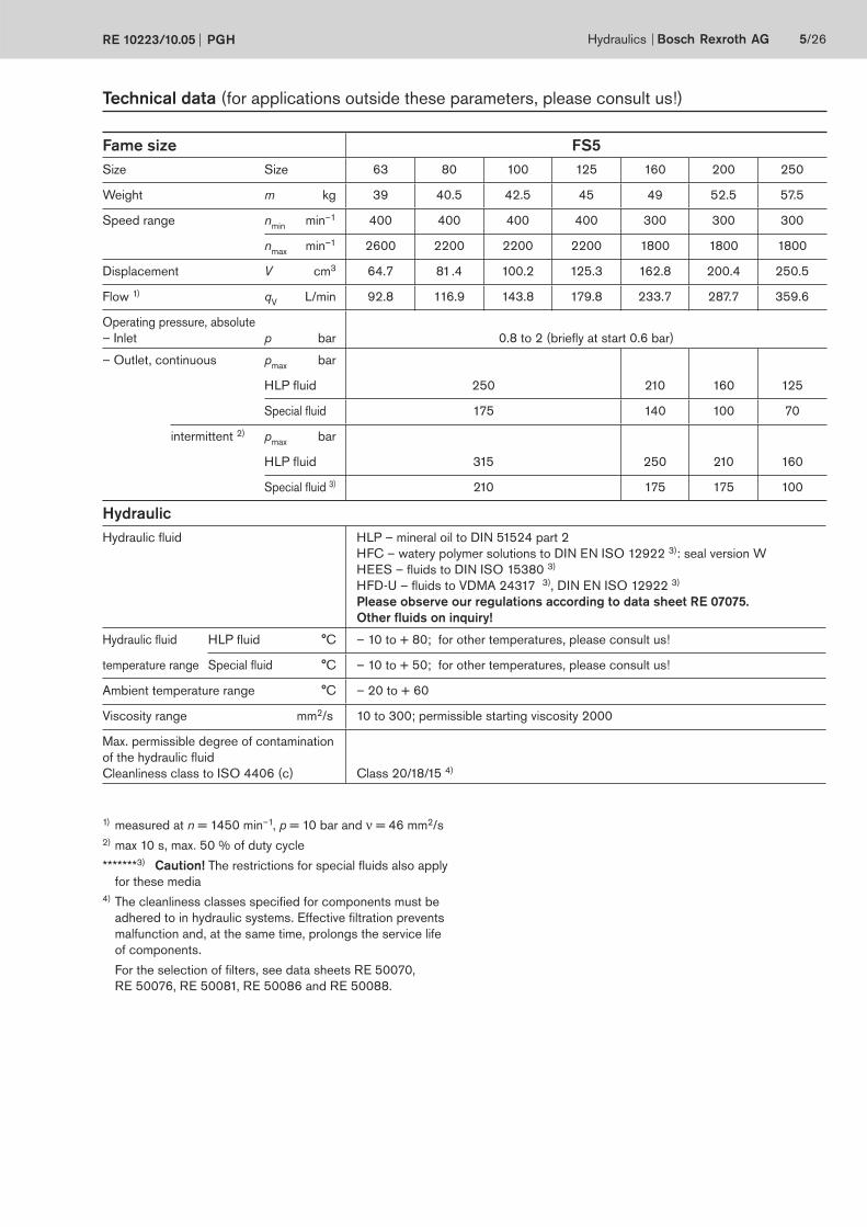
Hydraulics Bosch Rexroth AGRE 10223/10.05 PGH 5/26
Technical data (for applications outside these parameters, please consult us!)
Hydraulic
Hydraulic fluid HLP – mineral oil to DIN 51524 part 2
HFC – watery polymer solutions to DIN EN ISO 12922 3): seal version W
HEES – fluids to DIN ISO 15380 3)
HFD-U – fluids to VDMA 24317 3), DIN EN ISO 12922 3)
Please observe our regulations according to data sheet RE 07075.
Other fluids on inquiry!
Hydraulic fluid HLP fluid °C – 10 to + 80; for other temperatures, please consult us!
temperature range Special fluid °C – 10 to + 50; for other temperatures, please consult us!
Ambient temperature range °C – 20 to + 60
Viscosity range mm2/s 10 to 300; permissible starting viscosity 2000
Max. permissible degree of contamination
of the hydraulic fluid
Cleanliness class to ISO 4406 (c) Class 20/18/15 4)
1) measured at n = 1450 min–1, p = 10 bar and ν = 46 mm2/s
2) max 10 s, max. 50 % of duty cycle
*******3) Caution! The restrictions for special fluids also apply
for these media
4) The cleanliness classes specified for components must be
adhered to in hydraulic systems. Effective filtration prevents
malfunction and, at the same time, prolongs the service life
of components.
For the selection of filters, see data sheets RE 50070,
RE 50076, RE 50081, RE 50086 and RE 50088.
Fame size FS5
Size Size 63 80 100 125 160 200 250
Weight m kg 39 40.5 42.5 45 49 52.5 57.5
Speed range nmin
min–1 400 400 400 400 300 300 300
nmax
min–1 2600 2200 2200 2200 1800 1800 1800
Displacement V cm3 64.7 81.4 100.2 125.3 162.8 200.4 250.5
Flow 1) qV
L/min 92.8 116.9 143.8 179.8 233.7 287.7 359.6
Operating pressure, absolute
– Inlet p bar 0.8 to 2 (briefly at start 0.6 bar)
– Outlet, continuous pmax
bar
HLP fluid 250 210 160 125
Special fluid 175 140 100 70
intermittent 2) pmax
bar
HLP fluid 315 250 210 160
Special fluid 3) 210 175 175 100
100
90
80
70
60
500 50 100 150 200 250 300 350
25
20
15
10
5
0 50 100 150 200 250 300 350
16
14
12
10
8
6
4
2
0 50 100 150 200 250 300 350
6/26 Bosch Rexroth AG Hydraulics PGH RE 10223/10.05
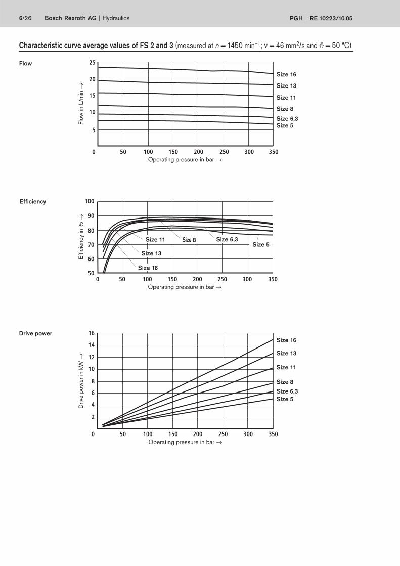
Characteristic curve average values of FS 2 and 3 (measured at n = 1450 min–1; ν = 46 mm2/s and ϑ = 50 °C)
Size 6,3
Flow
Efficiency
Effic
iency
in %
→
Operating pressure in bar →
Operating pressure in bar →
Flo
w in L
/min
→
Drive power
Drive
pow
er
in k
W →
Operating pressure in bar →
Size 16
Size 13
Size 11
Size 8
Size 6,3
Size 16
Size 13
Size 11
Size 8
Size 6,3
Size 16
Size 13
Size 11 Size 8
Size 5
Size 5
Size 5
66
64
62
60
58
56
54
52
10 30 40 50 70 110 150 190 270 290230 310 330 35020
50
48
46
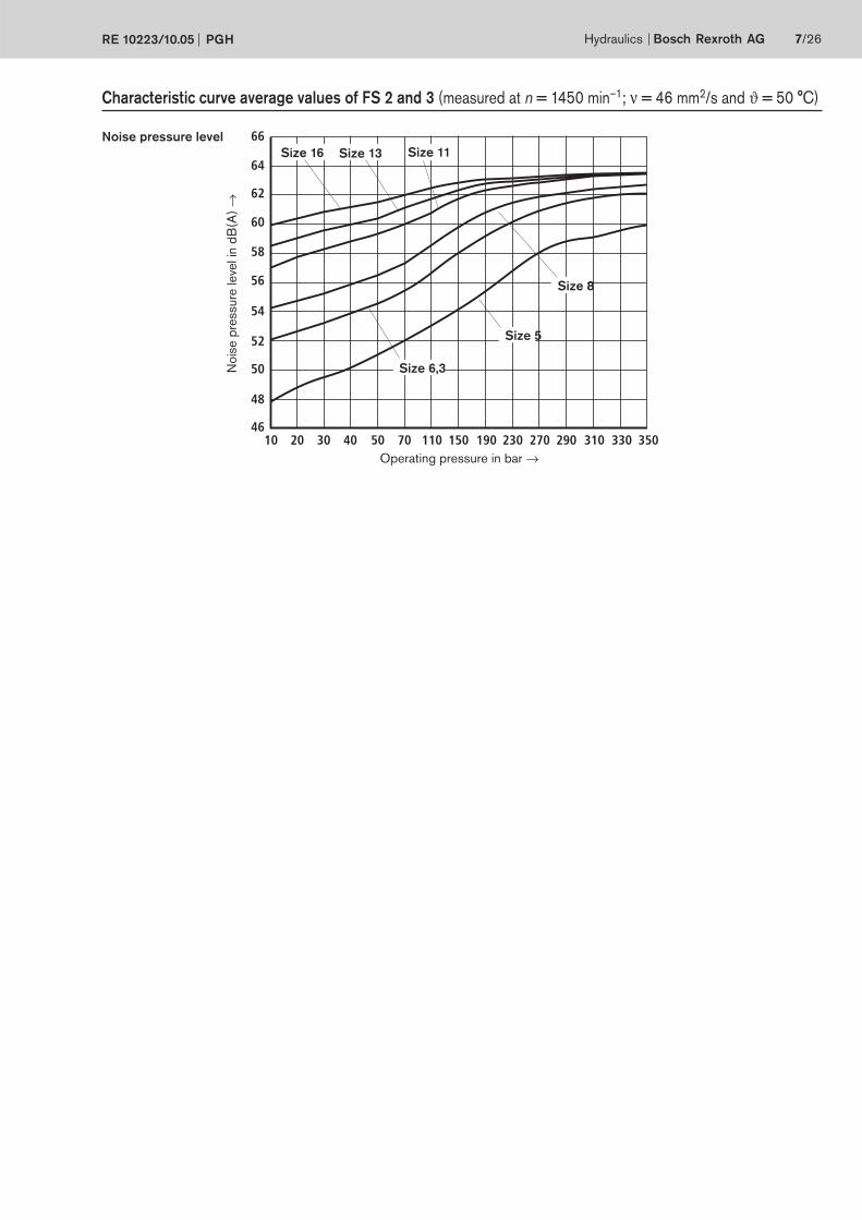
Hydraulics Bosch Rexroth AGRE 10223/10.05 PGH 7/26
Noise pressure level
Operating pressure in bar →
Nois
e p
ressure
leve
l in
dB
(A)
→
Size 6,3
Size 16 Size 13 Size 11
Size 8
Size 5
Characteristic curve average values of FS 2 and 3 (measured at n = 1450 min–1; ν = 46 mm2/s and ϑ = 50 °C)
0 25
15
75
50 75 100 125 150 175 200 225 250 275 300
30
45
60
30
150
60
90
120
0 20 21040 60 80 100 120 140 160 180 200
0
60
100
30050
70
80
90
50100 150 200 25025 75 125 175 225 275
60
100
70
80
90
500 20 21040 60 80 100 120 140 160 180 200
8/26 Bosch Rexroth AG Hydraulics PGH RE 10223/10.05
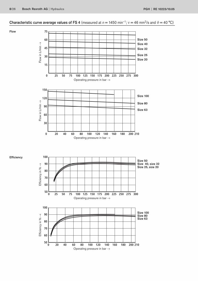
Flow
Efficiency
Flo
w in L
/min
→E
ffic
iency
in %
→E
ffic
iency
in %
→
Operating pressure in bar →
Flo
w in L
/min
→Size 50
Size 40
Size 32
Size 25
Size 20
Size 100
Size 80
Size 63
Size 50Size 40, size 32Size 25, size 20
Size 100Size 80Size 63
Characteristic curve average values of FS 4 (measured at n = 1450 min–1; ν = 46 mm2/s and ϑ = 40 °C)
Operating pressure in bar →
Operating pressure in bar →
Operating pressure in bar →
0 25
10
50 75 100 125 150 175 200 225 250 275 300
20
30
40
50
60
0 25
54
64
50 75 100 125 150 175 200 225 250 275 300
56
58
60
62
52
66
0 20 40 60 80 100
54
64
56
58
60
62
52
120 140 160 180 200 210
66
Hydraulics Bosch Rexroth AGRE 10223/10.05 PGH 9/26
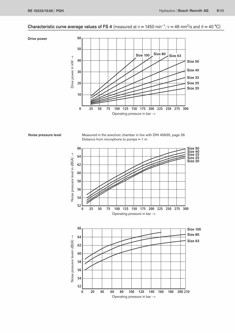
Drive power
Noise pressure level
Drive
pow
er
in k
W →
Measured in the anechoic chamber in line with DIN 45635, page 26
Distance from microphone to pumps = 1 m
Size 50Size 40Size 32Size 25Size 20
Size 100
Size 80
Size 63
Size 50
Size 40
Size 32
Size 25
Size 20
Size 63
Nois
e p
resusre
leve
l in
dB
(A)
→
Characteristic curve average values of FS 4 (measured at n = 1450 min–1; ν = 46 mm2/s and ϑ = 40 °C)
Operating pressure in bar →
Operating pressure in bar →
Operating pressure in bar →
No
ise p
resusre
leve
in d
B(A
) →
Size 80Size 100
0 25
50
50 75 100 125 150 175 200 225 250 275 300
100
150
200
20 40 60 80 100
200
250
300
350
150
400
120 140 160 180 200 2100
0
60
100
30050
70
80
90
50100 150 200 25025 75 125 175 225 275
60
100
70
80
90
500 20 40 60 80 100 120 140 160 180 200 210
10/26 Bosch Rexroth AG Hydraulics PGH RE 10223/10.05
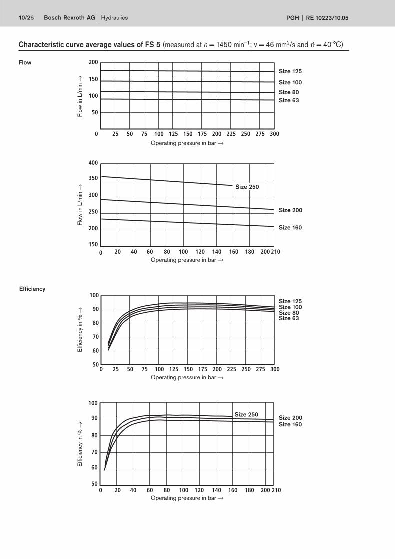
Flow
Efficiency
Size 125
Size 100
Size 80
Size 63
Size 200
Size 250
Size 160
Size 125Size 100Size 80Size 63
Size 200
Size 160
Size 250
Characteristic curve average values of FS 5 (measured at n = 1450 min–1; ν = 46 mm2/s and ϑ = 40 °C)
Operating pressure in bar →
Operating pressure in bar →
Operating pressure in bar →
Operating pressure in bar →
Effic
iency
in %
→Flo
w in L
/min
→E
ffic
iency
in %
→Flo
w in L
/min
→

0 25
20
100
50 75 100 125 150 175 200 225 250 275 300
40
60
80
0 25
62
72
50 75 100 125 150 175 200 225 250 275 300
64
66
68
70
60
74
0
64
74
20 40 60 80 100
66
68
70
72
62
76
120 140 160 180 200 210
Hydraulics Bosch Rexroth AGRE 10223/10.05 PGH 11/26
Measured in the anechoic chamber in line with DIN 45635, page 26
Distance from microphone to pumps = 1 m
Drive power
Noise pressure level
Size 125
Size 100
Size 80
Size 63
Size 250
Size 125
Size 100
Size 80
Size 63
Size 200 Size 160
Size 200
Size 160
Size 250
Characteristic curve average values of FS 5 (measured at n = 1450 min–1; ν = 46 mm2/s and ϑ = 40 °C)
Drive
pow
er
in k
W →
Nois
e p
ressure
leve
l in
dB
(A)
→
Operating pressure in bar →
No
ise p
ressure
leve
l in
dB
(A)
→
Operating pressure in bar →
Operating pressure in bar →
35
4
ø82,
55 h
8 6,2
P
41 L1
L2
S
ø18
h7
130106,4
48 50
1157
50
20,5
6 h9
L3
S
2)
3)
10,5
24
4
ø82,
55 h
8 6,2
P
31,5 L1
L2
S
130106,4
48 50
1157
50
L3
S
2)
3)
12/26 Bosch Rexroth AG Hydraulics PGH RE 10223/10.05
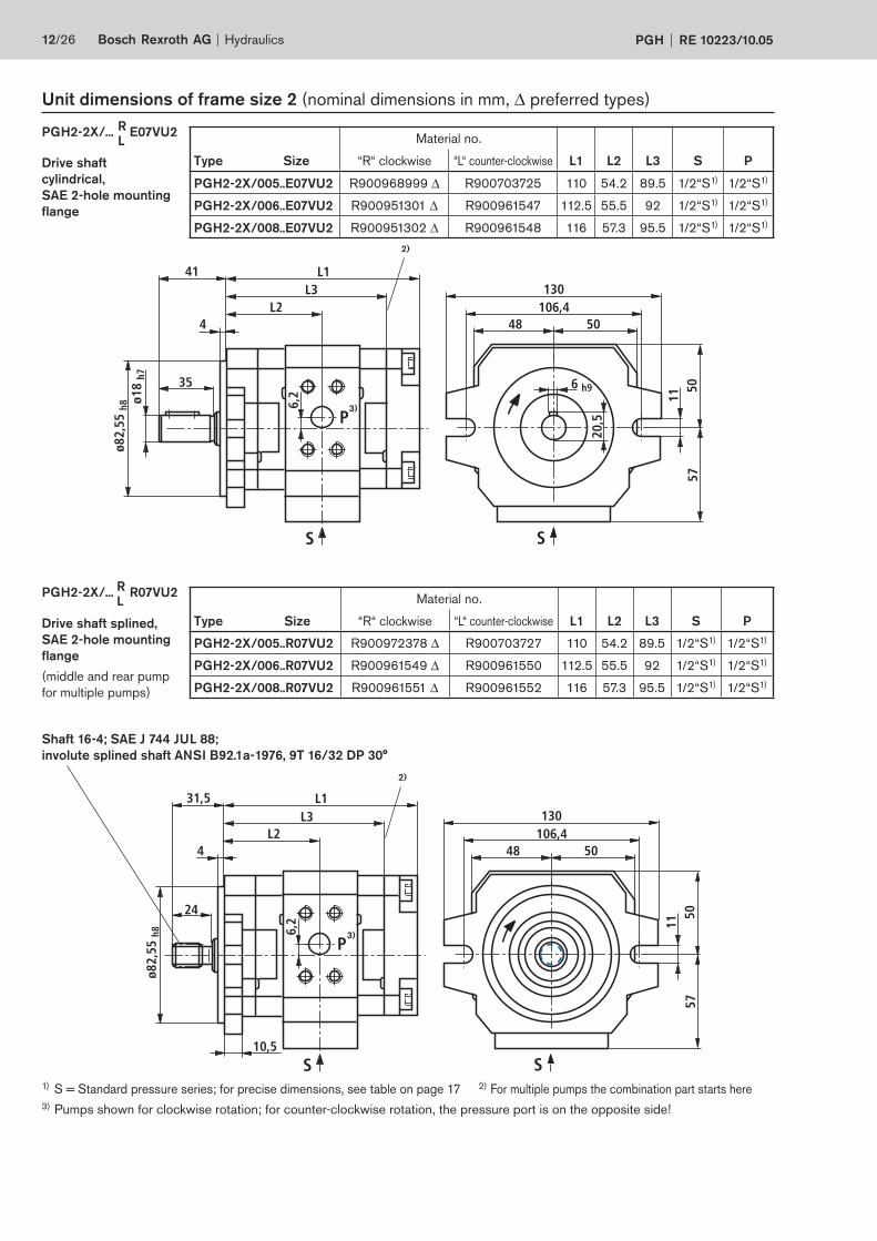
Unit dimensions of frame size 2 (nominal dimensions in mm, ∆ preferred types)
Drive shaft
cylindrical,
SAE 2-hole mounting
flange
PGH2-2X/... E07VU2
Material no.
Type Size “R“ clockwise “L“ counter-clockwise L1 L2 L3 S P
PGH2-2X/005..R07VU2 R900972378 ∆ R900703727 110 54.2 89.5 1/2“S1) 1/2“S1)
PGH2-2X/006..R07VU2 R900961549 ∆ R900961550 112.5 55.5 92 1/2“S1) 1/2“S1)
PGH2-2X/008..R07VU2 R900961551 ∆ R900961552 116 57.3 95.5 1/2“S1) 1/2“S1)
Drive shaft splined,
SAE 2-hole mounting
flange
(middle and rear pump
for multiple pumps)
1) S = Standard pressure series; for precise dimensions, see table on page 17 2) For multiple pumps the combination part starts here
3) Pumps shown for clockwise rotation; for counter-clockwise rotation, the pressure port is on the opposite side!
PGH2-2X/... R07VU2
Shaft 16-4; SAE J 744 JUL 88;
involute splined shaft ANSI B92.1a-1976, 9T 16/32 DP 30°
R
L
R
L
Material no.
Type Size “R“ clockwise “L“ counter-clockwise L1 L2 L3 S P
PGH2-2X/005..E07VU2 R900968999 ∆ R900703725 110 54.2 89.5 1/2“S1) 1/2“S1)
PGH2-2X/006..E07VU2 R900951301 ∆ R900961547 112.5 55.5 92 1/2“S1) 1/2“S1)
PGH2-2X/008..E07VU2 R900951302 ∆ R900961548 116 57.3 95.5 1/2“S1) 1/2“S1)
10,5
40
4
ø101
,6 h
8ø2
0 h6
6,2
P
41 L1
L2
S
176146
48
Ø13
5750
6 h9
50
L3
S
22,5
2)
3)
10,5
24
4
ø82,
55 h
8 6,2
P
31,5 L1
L2
S
130106,4
48 50
1157
50
L3
S
2)
3)
Hydraulics Bosch Rexroth AGRE 10223/10.05 PGH 13/26
Unit dimensions for frame size 3 (nominal dimensions in mm, ∆ preferred types)
Material no.
Type Size “R“ clockwise “L“ counter-clockwise L1 L2 L3 S P
PGH3-2X/011..E07VU2 R900951303 ∆ R900961553 128 66.5 107.5 1“S1) 1/2“S1)
PGH3-2X/013..E07VU2 R900951304 ∆ R900961554 133 69 112.5 1“S1) 1/2“S1)
PGH3-2X/016..E07VU2 R900951305 ∆ R900961555 138 71.5 117.5 1“S1) 1/2“S1)
Drive shaft
cylindrical,
SAE 2-hole mounting
flange
PGH3-2X/... E07VU2
Material no.
Typ Size “R“ clockwise “L“ counter-clockwise L1 L2 L3 S P
PGH3-2X/011..R07VU2 R900961556 ∆ R900961559 121.5 60 101 1“S1) 1/2“S1)
PGH3-2X/013..R07VU2 R900961557 ∆ R900961560 126.5 62.5 106 1“S1) 1/2“S1)
PGH3-2X/016..R07VU2 R900961558 ∆ R900961561 131.5 65 111 1“S1) 1/2“S1)
Drive shaft splined,
SAE 2-hole mounting
flange
(middle and rear pump
for multiple pumps)
PGH3-2X/... R07VU2
Shaft 16-4; SAE J 744 JUL 88;
involute splined shaft ANSI B92.1a-1976, 9T 16/32 DP 30°
R
L
R
L
S = Standard pressure series; for precise dimensions, see table on page 17 2) For multiple pumps the combination part starts here
3) Pumps shown for clockwise rotation; for counter-clockwise rotation, the pressure port is on the opposite side!
30
12,5
60
9
ø101
,6 h
8ø2
5 j6
5,4
P
70 L1
L2172146
70
28
13,5
74,6
69,4
S 70
8 h9
L3
2)
3)
4412,5
60
9
ø100
h8
ø25
j6
5,4
P
70 L1
L2
S
28
8 h9
70 70
1174
,669
,4
146
125
L3
2)
3)
14/26 Bosch Rexroth AG Hydraulics PGH RE 10223/10.05
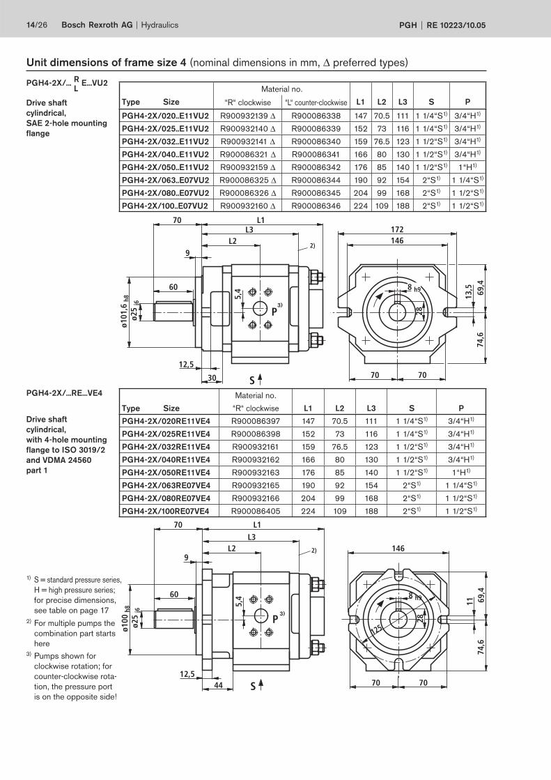
Unit dimensions of frame size 4 (nominal dimensions in mm, ∆ preferred types)
R
L Material no.
Type Size “R“ clockwise “L“ counter-clockwise L1 L2 L3 S P
PGH4-2X/020..E11VU2 R900932139 ∆ R900086338 147 70.5 111 1 1/4“S1) 3/4“H1)
PGH4-2X/025..E11VU2 R900932140 ∆ R900086339 152 73 116 1 1/4“S1) 3/4“H1)
PGH4-2X/032..E11VU2 R900932141 ∆ R900086340 159 76.5 123 1 1/2“S1) 3/4“H1)
PGH4-2X/040..E11VU2 R900086321 ∆ R900086341 166 80 130 1 1/2“S1) 3/4“H1)
PGH4-2X/050..E11VU2 R900932159 ∆ R900086342 176 85 140 1 1/2“S1) 1“H1)
PGH4-2X/063..E07VU2 R900086325 ∆ R900086344 190 92 154 2“S1) 1 1/4“S1)
PGH4-2X/080..E07VU2 R900086326 ∆ R900086345 204 99 168 2“S1) 1 1/2“S1)
PGH4-2X/100..E07VU2 R900932160 ∆ R900086346 224 109 188 2“S1) 1 1/2“S1)
Drive shaft
cylindrical,
with 4-hole mounting
flange to ISO 3019/2
and VDMA 24560
part 1
Drive shaft
cylindrical,
SAE 2-hole mounting
flange
PGH4-2X/... E...VU2
PGH4-2X/...RE...VE4
1) S = standard pressure series,
H = high pressure series;
for precise dimensions,
see table on page 17
2) For multiple pumps the
combination part starts
here
Material no.
Type Size “R“ clockwise L1 L2 L3 S P
PGH4-2X/020RE11VE4 R900086397 147 70.5 111 1 1/4“S1) 3/4“H1)
PGH4-2X/025RE11VE4 R900086398 152 73 116 1 1/4“S1) 3/4“H1)
PGH4-2X/032RE11VE4 R900932161 159 76.5 123 1 1/2“S1) 3/4“H1)
PGH4-2X/040RE11VE4 R900932162 166 80 130 1 1/2“S1) 3/4“H1)
PGH4-2X/050RE11VE4 R900932163 176 85 140 1 1/2“S1) 1“H1)
PGH4-2X/063RE07VE4 R900932165 190 92 154 2“S1) 1 1/4“S1)
PGH4-2X/080RE07VE4 R900932166 204 99 168 2“S1) 1 1/2“S1)
PGH4-2X/100RE07VE4 R900086405 224 109 188 2“S1) 1 1/2“S1)
3) Pumps shown for
clockwise rotation; for
counter-clockwise rota-
tion, the pressure port
is on the opposite side!
ø 83
30
12,5
38
9
ø101
,6 h
8 5,4
P
45,9 L1
L2172146
70
13,5
74,6
69,4
S70
L3
Shaft 25-4; SAE J 744 JUL 88;
involute splined shaft
ANSI B92.1a-1976,
15T 16/32 DP 30°
2)
3)
Hydraulics Bosch Rexroth AGRE 10223/10.05 PGH 15/26
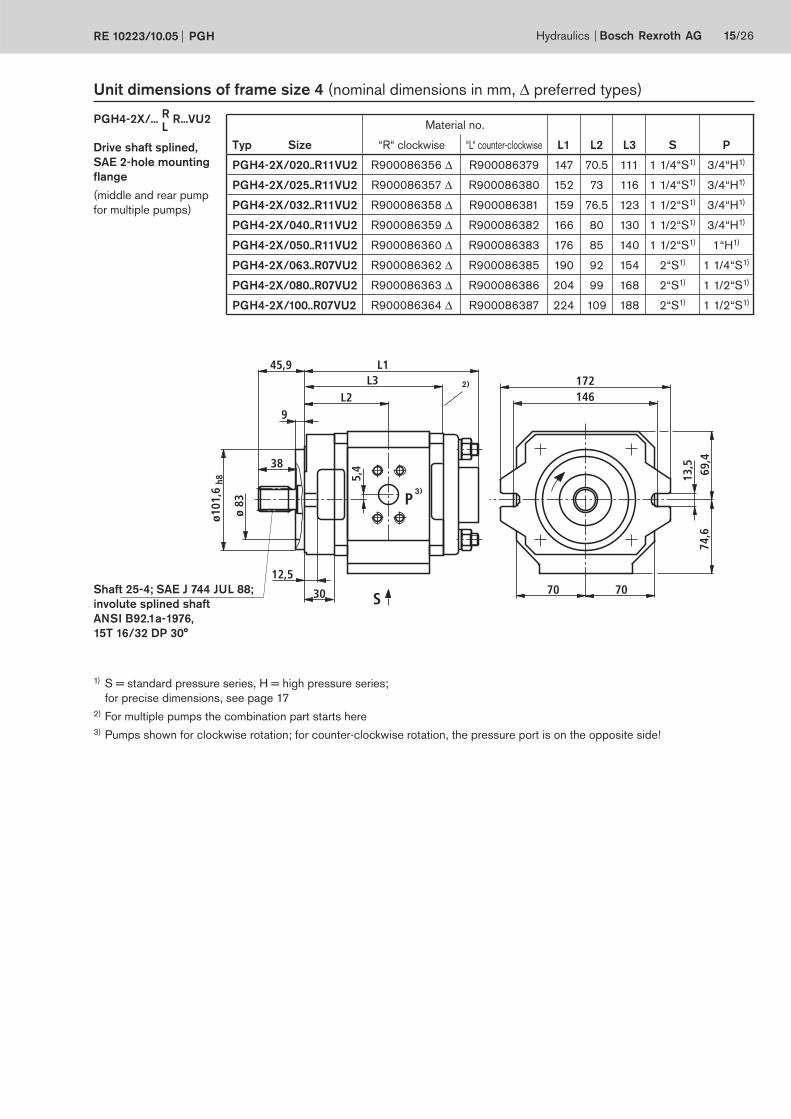
Unit dimensions of frame size 4 (nominal dimensions in mm, ∆ preferred types)
R
L Material no.
Typ Size “R“ clockwise “L“ counter-clockwise L1 L2 L3 S P
PGH4-2X/020..R11VU2 R900086356 ∆ R900086379 147 70.5 111 1 1/4“S1) 3/4“H1)
PGH4-2X/025..R11VU2 R900086357 ∆ R900086380 152 73 116 1 1/4“S1) 3/4“H1)
PGH4-2X/032..R11VU2 R900086358 ∆ R900086381 159 76.5 123 1 1/2“S1) 3/4“H1)
PGH4-2X/040..R11VU2 R900086359 ∆ R900086382 166 80 130 1 1/2“S1) 3/4“H1)
PGH4-2X/050..R11VU2 R900086360 ∆ R900086383 176 85 140 1 1/2“S1) 1“H1)
PGH4-2X/063..R07VU2 R900086362 ∆ R900086385 190 92 154 2“S1) 1 1/4“S1)
PGH4-2X/080..R07VU2 R900086363 ∆ R900086386 204 99 168 2“S1) 1 1/2“S1)
PGH4-2X/100..R07VU2 R900086364 ∆ R900086387 224 109 188 2“S1) 1 1/2“S1)
Drive shaft splined,
SAE 2-hole mounting
flange
(middle and rear pump
for multiple pumps)
PGH4-2X/... R...VU2
1) S = standard pressure series, H = high pressure series;
for precise dimensions, see page 17
2) For multiple pumps the combination part starts here
3) Pumps shown for clockwise rotation; for counter-clockwise rotation, the pressure port is on the opposite side!
48
19
82
9
ø152
,4 h
8ø4
0 j6
7,7
P
92 L1
L2267
228,6
99
43
2210
5,3
98,7
S 99
12 h9
L32)
3)
7018
82
9
ø160
h8
ø40
j6
7,7
92 L1
L2
S
43
12h9
99 99
1810
5,3
98,7
230
200P
L3
2)
3)
16/26 Bosch Rexroth AG Hydraulics PGH RE 10223/10.05
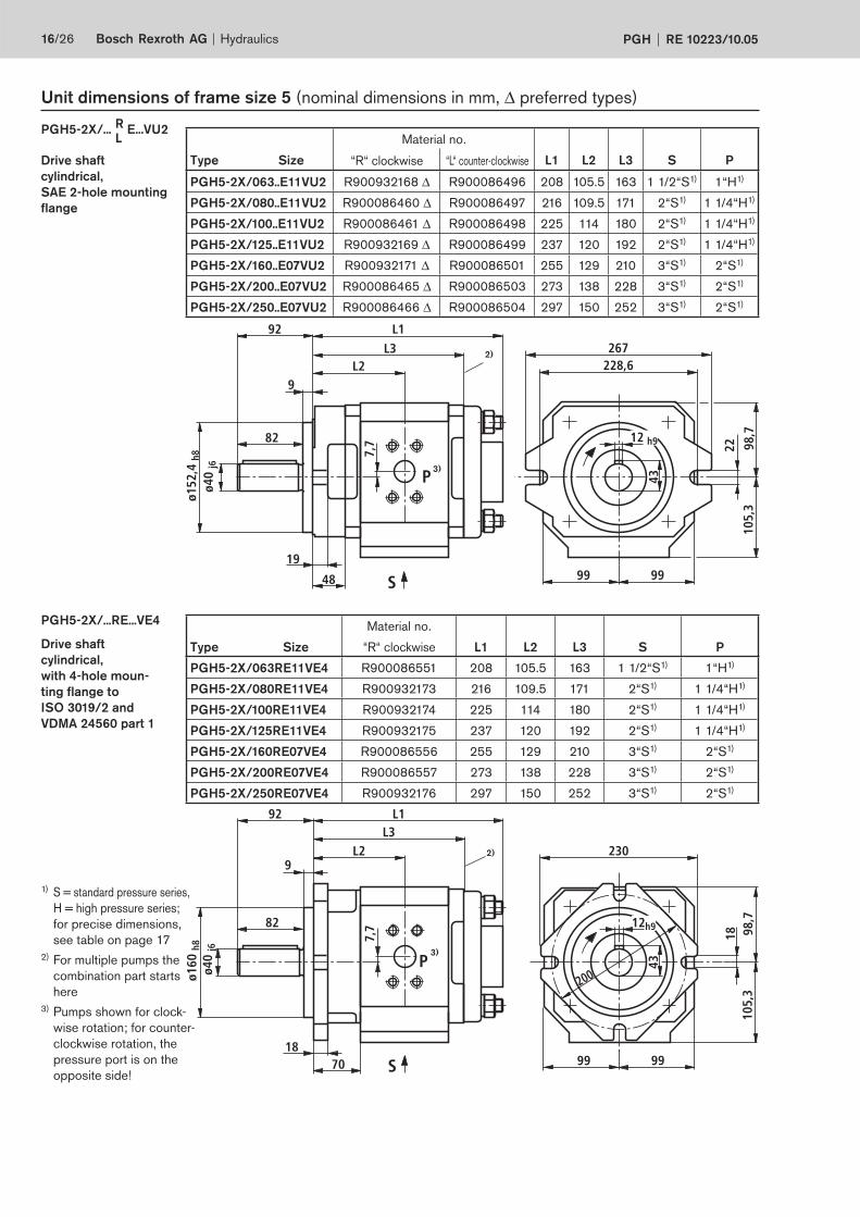
Unit dimensions of frame size 5 (nominal dimensions in mm, ∆ preferred types)
R
L Material no.
Type Size “R“ clockwise “L“ counter-clockwise L1 L2 L3 S P
PGH5-2X/063..E11VU2 R900932168 ∆ R900086496 208 105.5 163 1 1/2“S1) 1“H1)
PGH5-2X/080..E11VU2 R900086460 ∆ R900086497 216 109.5 171 2“S1) 1 1/4“H1)
PGH5-2X/100..E11VU2 R900086461 ∆ R900086498 225 114 180 2“S1) 1 1/4“H1)
PGH5-2X/125..E11VU2 R900932169 ∆ R900086499 237 120 192 2“S1) 1 1/4“H1)
PGH5-2X/160..E07VU2 R900932171 ∆ R900086501 255 129 210 3“S1) 2“S1)
PGH5-2X/200..E07VU2 R900086465 ∆ R900086503 273 138 228 3“S1) 2“S1)
PGH5-2X/250..E07VU2 R900086466 ∆ R900086504 297 150 252 3“S1) 2“S1)
Drive shaft
cylindrical,
SAE 2-hole mounting
flange
PGH5-2X/... E...VU2
Drive shaft
cylindrical,
with 4-hole moun-
ting flange to
ISO 3019/2 and
VDMA 24560 part 1
PGH5-2X/...RE...VE4Material no.
Type Size “R“ clockwise L1 L2 L3 S P
PGH5-2X/063RE11VE4 R900086551 208 105.5 163 1 1/2“S1) 1“H1)
PGH5-2X/080RE11VE4 R900932173 216 109.5 171 2“S1) 1 1/4“H1)
PGH5-2X/100RE11VE4 R900932174 225 114 180 2“S1) 1 1/4“H1)
PGH5-2X/125RE11VE4 R900932175 237 120 192 2“S1) 1 1/4“H1)
PGH5-2X/160RE07VE4 R900086556 255 129 210 3“S1) 2“S1)
PGH5-2X/200RE07VE4 R900086557 273 138 228 3“S1) 2“S1)
PGH5-2X/250RE07VE4 R900932176 297 150 252 3“S1) 2“S1)
1) S = standard pressure series,
H = high pressure series;
for precise dimensions,
see table on page 17
2) For multiple pumps the
combination part starts
here
3) Pumps shown for clock-
wise rotation; for counter-
clockwise rotation, the
pressure port is on the
opposite side!
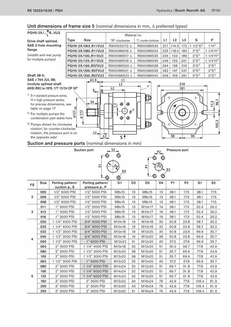
D4
S2
D3
S1
P2
D1
P1
D2
ø 11
3
5717
54
9
ø127
h8 7,
7P
61,9 L1
L2210181
99
17,5
105,
398
,7
S 99
L32)
3)
Hydraulics Bosch Rexroth AGRE 10223/10.05 PGH 17/26
Unit dimensions of frame size 5 (nominal dimensions in mm, ∆ preferred types)R
L
Suction and pressure ports (nominal dimensions in mm)
FSSize Porting pattern/
suction p., S
Porting pattern/
pressure p., P
D1 D2 D3 D4 P1 P2 S1 S2
005 1/2" 5000 PSI 1/2" 5000 PSI M8x15 13 M8x15 13 38.1 17.5 38.1 17.5
2 006 1/2" 5000 PSI 1/2" 5000 PSI M8x15 13 M8x15 13 38.1 17.5 38.1 17.5
008 1/2" 5000 PSI 1/2" 5000 PSI M8x15 13 M8x15 13 38.1 17.5 38.1 17.5
011 1" 3000 PSI 1/2" 5000 PSI M8x15 13 M10x17 19 38.1 17.5 52.4 26.2
3 013 1" 3000 PSI 1/2" 5000 PSI M8x15 13 M10x17 19 38.1 17.5 52.4 26.2
016 1" 3000 PSI 1/2" 5000 PSI M8x15 13 M10x17 19 38.1 17.5 52.4 26.2
020 1 1/4" 4000 PSI 3/4" 6000 PSI M10x18 19 M10x18 30 50.8 23.8 58.7 30.2
025 1 1/4" 4000 PSI 3/4" 6000 PSI M10x18 19 M10x18 32 50.8 23.8 58.7 30.2
032 1 1/2" 3000 PSI 3/4" 6000 PSI M10x18 19 M12x20 35 50.8 23.8 69.9 35.7
4040 1 1/2" 3000 PSI 3/4" 6000 PSI M10x18 19 M12x20 38 50.8 23.8 69.9 35.7
050 1 1/2" 3000 PSI 1" 6000 PSI M12x22 21 M12x20 40 57.2 27.8 69.9 35.7
063 2" 3000 PSI 1 1/4" 4000 PSI M10x18 32 M12x20 51 30.2 58.7 77.8 42.9
080 2" 3000 PSI 1 1/2" 3000 PSI M12x20 38 M12x20 51 35.7 69.9 77.8 42.9
100 2" 3000 PSI 1 1/2" 3000 PSI M12x20 38 M12x20 51 35.7 69.9 77.8 42.9
063 1 1/2" 3000 PSI 1" 6000 PSI M12x22 25 M12x20 40 57.2 27.8 69.9 35.7
080 2" 3000 PSI 1 1/4" 6000 PSI M14x24 32 M12x20 51 66.7 31.8 77.8 42.9
100 2" 3000 PSI 1 1/4" 6000 PSI M14x24 32 M12x20 51 66.7 31.8 77.8 42.9
5 125 2" 3000 PSI 1 1/4" 6000 PSI M14x24 32 M12x20 51 66.7 31.8 77.8 42.9
160 3" 3000 PSI 2" 3000 PSI M12x20 34 M16x24 76 42.9 77.8 106.4 61.9
200 3" 3000 PSI 2" 3000 PSI M12x20 43 M16x24 76 42.9 77.8 106.4 61.9
250 3" 3000 PSI 2" 3000 PSI M12x20 51 M16x24 76 42.9 77.8 106.4 61.9
Shaft 38-4;
SAE J 744 JUL 88;
involute splined shaft
ANSI B92.1a-1976, 17T 12/24 DP 30°
Material no.
Type Size “R“ clockwise “L“ counter-clockwise L1 L2 L3 S P
PGH5-2X/063..R11VU2 R900932172 ∆ R900086533 217 114.5 172 1 1/2“S1) 1“H1)
PGH5-2X/080..R11VU2 R900086516 ∆ R900086534 225 118.5 180 2“S1) 1 1/4“H1)
PGH5-2X/100..R11VU2 R900086517 ∆ R900086535 234 123 189 2“S1) 1 1/4“H1)
PGH5-2X/125..R11VU2 R900086518 ∆ R900086536 246 129 201 2“S1) 1 1/4“H1)
PGH5-2X/160..R07VU2 R900086520 ∆ R900086538 264 138 219 3“S1) 2“S1)
PGH5-2X/200..R07VU2 R900086521 ∆ R900086539 282 147 237 3“S1) 2“S1)
PGH5-2X/250..R07VU2 R900086522 ∆ R900086540 306 159 261 3“S1) 2“S1)
Drive shaft splined,
SAE 2-hole mounting
flange
(middle and rear pump
for multiple pumps)
PGH5-2X/... R...VU2
1) S = standard pressure series,
H = high pressure series;
for precise dimensions, see
table on page 17
2) For multiple pumps the
combination part starts here
Suction port Pressure port
3) Pumps shown for clockwise
rotation; for counter-clockwise
rotation, the pressure port is on
the opposite side!
18/26 Bosch Rexroth AG Hydraulics PGH RE 10223/10.05
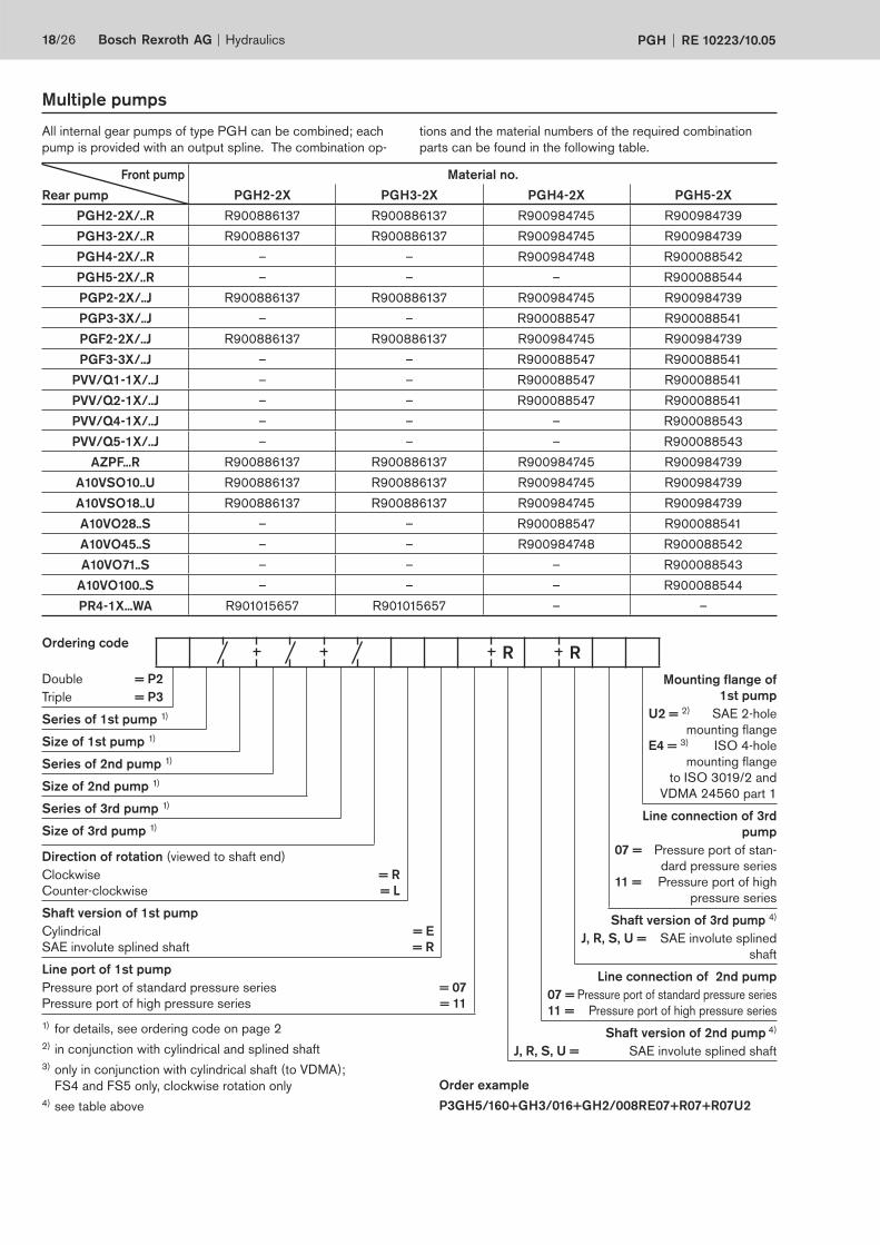
Multiple pumps
All internal gear pumps of type PGH can be combined; each
pump is provided with an output spline. The com bi na ti on op-
1) for details, see ordering code on page 2
2) in conjunction with cylindrical and splined shaft
3) only in conjunction with cylindrical shaft (to VDMA);
FS4 and FS5 only, clockwise rotation only
4) see table above
Ordering code
Order example
P3GH5/160+GH3/016+GH2/008RE07+R07+R07U2
Front pump Material no.
Rear pump PGH2-2X PGH3-2X PGH4-2X PGH5-2X
PGH2-2X/..R R900886137 R900886137 R900984745 R900984739
PGH3-2X/..R R900886137 R900886137 R900984745 R900984739
PGH4-2X/..R – – R900984748 R900088542
PGH5-2X/..R – – – R900088544
PGP2-2X/..J R900886137 R900886137 R900984745 R900984739
PGP3-3X/..J – – R900088547 R900088541
PGF2-2X/..J R900886137 R900886137 R900984745 R900984739
PGF3-3X/..J – – R900088547 R900088541
PVV/Q1-1X/..J – – R900088547 R900088541
PVV/Q2-1X/..J – – R900088547 R900088541
PVV/Q4-1X/..J – – – R900088543
PVV/Q5-1X/..J – – – R900088543
AZPF...R R900886137 R900886137 R900984745 R900984739
A10VSO10..U R900886137 R900886137 R900984745 R900984739
A10VSO18..U R900886137 R900886137 R900984745 R900984739
A10VO28..S – – R900088547 R900088541
A10VO45..S – – R900984748 R900088542
A10VO71..S – – – R900088543
A10VO100..S – – – R900088544
PR4-1X...WA R901015657 R901015657 – –
tions and the material numbers of the required combination
parts can be found in the following table.
Mounting flange of
1st pump
U2 = 2) SAE 2-hole
mounting flange
E4 = 3) ISO 4-hole
mounting flange
to ISO 3019/2 and
VDMA 24560 part 1
Line connection of 3rd
pump
07 = Pressure port of stan-
dard pressure series
11 = Pressure port of high
pressure series
Shaft version of 3rd pump 4)
J, R, S, U = SAE involute splined
shaft
Line connection of 2nd pump
07 = Pressure port of standard pressure series
11 = Pressure port of high pressure series
Shaft version of 2nd pump 4)
J, R, S, U = SAE involute splined shaft
Double = P2
Triple = P3
Series of 1st pump 1)
Size of 1st pump 1)
Series of 2nd pump 1)
Size of 2nd pump 1)
Series of 3rd pump 1)
Size of 3rd pump 1)
Direction of rotation (viewed to shaft end)
Clockwise = R
Counter-clockwise = L
Shaft version of 1st pump
Cylindrical = E
SAE involute splined shaft = R
Line port of 1st pump
Pressure port of standard pressure series = 07
Pressure port of high pressure series = 11
R R
49
P
S
97
21,2
S
P
26,9
21,2
26,9
44 69
S
P
P
S
Hydraulics Bosch Rexroth AGRE 10223/10.05 PGH 19/26
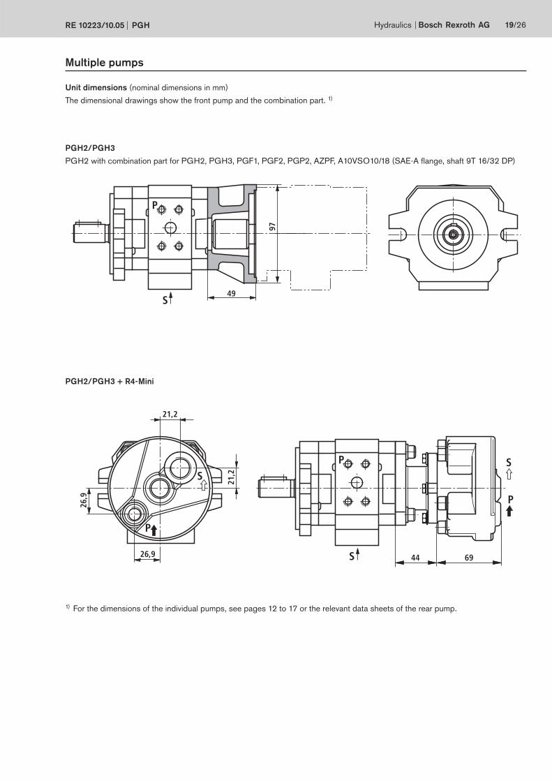
Multiple pumps
Unit dimensions (nominal dimensions in mm)
The dimensional drawings show the front pump and the combination part. 1)
PGH2/PGH3
PGH2 with combination part for PGH2, PGH3, PGF1, PGF2, PGP2, AZPF, A10VSO10/18 (SAE-A flange, shaft 9T 16/32 DP)
PGH2/PGH3 + R4-Mini
1) For the dimensions of the individual pumps, see pages 12 to 17 or the relevant data sheets of the rear pump.
20/26 Bosch Rexroth AG Hydraulics PGH RE 10223/10.05
77
P
S
Ø17
2
77
P
S
Ø17
2
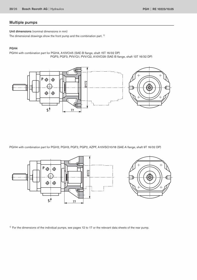
Multiple pumps
Unit dimensions (nominal dimensions in mm)
The dimensional drawings show the front pump and the combination part. 1)
PGH4
PGH4 with combination part for PGH4, A10VO45 (SAE-B flange, shaft 15T 16/32 DP)
PGP3, PGF3, PVV/Q1, PVV/Q2, A10VO28 (SAE-B flange, shaft 13T 16/32 DP)
PGH4 with combination part for PGH2, PGH3, PGF2, PGP2, AZPF, A10VSO10/18 (SAE-A flange, shaft 9T 16/32 DP)
1) For the dimensions of the individual pumps, see pages 12 to 17 or the relevant data sheets of the rear pump.
101
P
SØ
210
101
P
S
Ø21
0
101
P
S
Ø21
0
Hydraulics Bosch Rexroth AGRE 10223/10.05 PGH 21/26
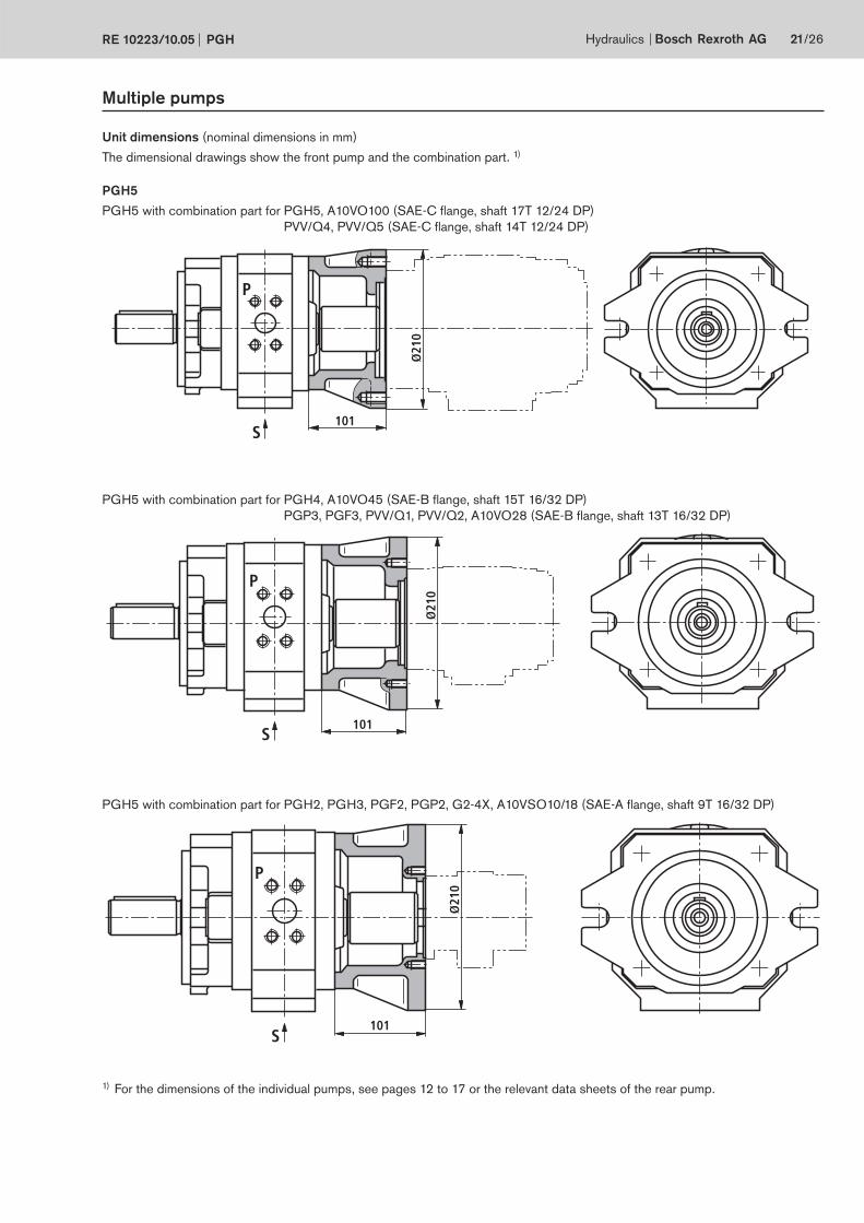
Multiple pumps
Unit dimensions (nominal dimensions in mm)
The dimensional drawings show the front pump and the combination part. 1)
PGH5
PGH5 with combination part for PGH5, A10VO100 (SAE-C flange, shaft 17T 12/24 DP)
PVV/Q4, PVV/Q5 (SAE-C flange, shaft 14T 12/24 DP)
1) For the dimensions of the individual pumps, see pages 12 to 17 or the relevant data sheets of the rear pump.
PGH5 with combination part for PGH4, A10VO45 (SAE-B flange, shaft 15T 16/32 DP)
PGP3, PGF3, PVV/Q1, PVV/Q2, A10VO28 (SAE-B flange, shaft 13T 16/32 DP)
PGH5 with combination part for PGH2, PGH3, PGF2, PGP2, G2-4X, A10VSO10/18 (SAE-A flange, shaft 9T 16/32 DP)
22/26 Bosch Rexroth AG Hydraulics PGH RE 10223/10.05
Engineering notes
Multiple pumps
• The general technical data are the same as for single pumps
(see pages 4 and 5).
• Combined pumps must all have the same direction of rota-
tion.
• The pump that requires the highest torque should be pro-
vided as first pump.
• The engineer must verify the maximum troughdrive torque
for each application. This is also valid for existing (coded)
multiple pumps.
Max. permissible torques in Nm:
Type Input torque Output torque
Cylindrical shaft ..E Splined shaft ..R
PGH2 100 120 75
PGH3 110 120 75
PGH4 450 450 280
PGH5 1100 1400 700
• The sum of torques in a multiple pump must not exceed the
max. input torque.
• Common suction is impossible.
• For strength and stability reasons, we recommend ISO
4-hole mounting flanges to VDMA “E4“ for combinations of
three or more pumps.
T : torque in Nm
∆p : operating pressure in bar
V : displacement in cm3
η : hydraulic-mechanical efficiency
T =∆p • V • 0.0159
η hydr.-mech.
• The drive torque of a pump stage can be calculated as fol-
lows:
• Before using pump combinations with different media,
please consult Industrial Hydraulics.
• Middle and rear pumps must have shaft version “R”
(splined).
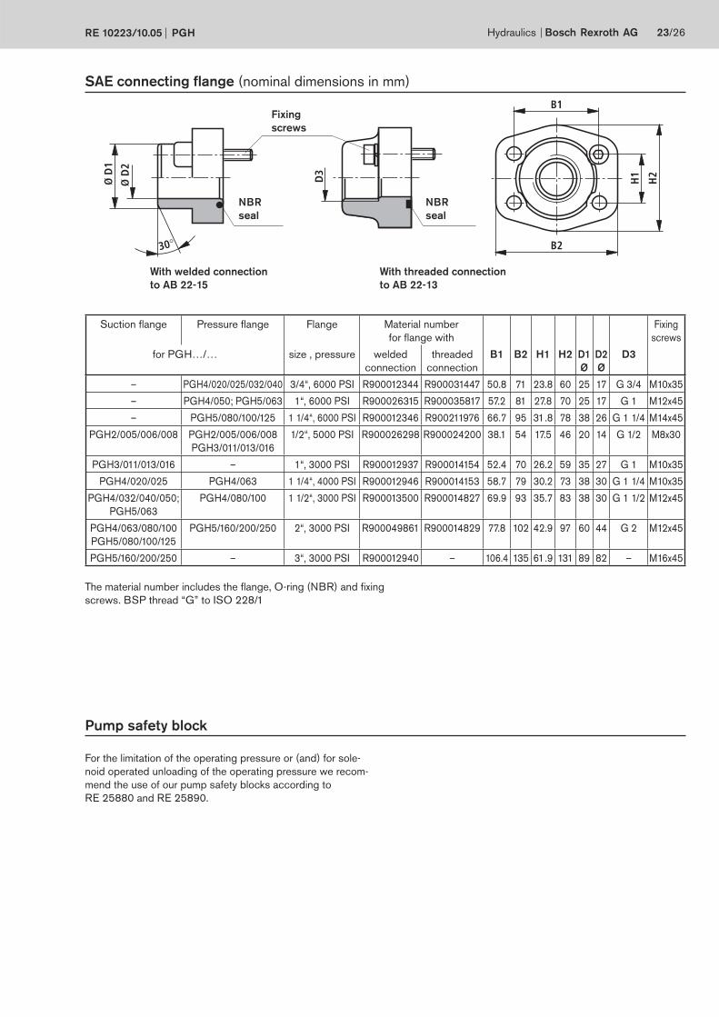
Ø D
2
Ø D
1
30°
H1D3
B1
H2
B2
Hydraulics Bosch Rexroth AGRE 10223/10.05 PGH 23/26
SAE connecting flange (nominal dimensions in mm)
Pump safety block
For the limitation of the operating pressure or (and) for sole-
noid operated unloading of the operating pressure we recom-
mend the use of our pump safety blocks according to
RE 25880 and RE 25890.
The material number includes the flange, O-ring (NBR) and fixing
screws. BSP thread “G” to ISO 228/1
With welded connection
to AB 22-15
With threaded connection
to AB 22-13
Fixing
screws
NBR
seal
NBR
seal
Suction flange Pressure flange Flange Material number
for flange with
Fixing
screws
for PGH…/… size , pressure welded
connection
threaded
connection
B1 B2 H1 H2 D1
Ø
D2
Ø
D3
– PGH4/020/025/032/040 3/4“, 6000 PSI R900012344 R900031447 50.8 71 23.8 60 25 17 G 3/4 M10x35
– PGH4/050; PGH5/063 1“, 6000 PSI R900026315 R900035817 57.2 81 27.8 70 25 17 G 1 M12x45
– PGH5/080/100/125 1 1/4“, 6000 PSI R900012346 R900211976 66.7 95 31.8 78 38 26 G 1 1/4 M14x45
PGH2/005/006/008 PGH2/005/006/008
PGH3/011/013/016
1/2“, 5000 PSI R900026298 R900024200 38.1 54 17.5 46 20 14 G 1/2 M8x30
PGH3/011/013/016 – 1“, 3000 PSI R900012937 R900014154 52.4 70 26.2 59 35 27 G 1 M10x35
PGH4/020/025 PGH4/063 1 1/4“, 4000 PSI R900012946 R900014153 58.7 79 30.2 73 38 30 G 1 1/4 M10x35
PGH4/032/040/050;
PGH5/063
PGH4/080/100 1 1/2“, 3000 PSI R900013500 R900014827 69.9 93 35.7 83 38 30 G 1 1/2 M12x45
PGH4/063/080/100
PGH5/080/100/125
PGH5/160/200/250 2“, 3000 PSI R900049861 R900014829 77.8 102 42.9 97 60 44 G 2 M12x45
PGH5/160/200/250 – 3“, 3000 PSI R900012940 – 106.4 135 61.9 131 89 82 – M16x45
24/26 Bosch Rexroth AG Hydraulics PGH RE 10223/10.05
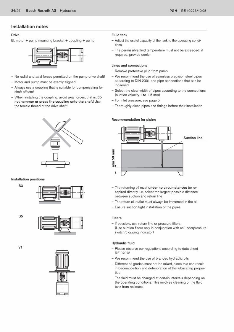
min
50
mm
Suction line
Drive
El. motor + pump mounting bracket + coupling + pump
– No radial and axial forces permitted on the pump drive shaft!
– Motor and pump must be exactly aligned!
– Always use a coupling that is suitable for compensating for
shaft offsets!
– When installing the coupling, avoid axial forces, that is, do
not hammer or press the coupling onto the shaft! Use
the female thread of the drive shaft!
Fluid tank
– Adjust the useful capacity of the tank to the operating condi-
tions
– The permissible fluid temperature must not be exceeded; if
required, provide cooler
Lines and connections
– Remove protective plug from pump
– We recommend the use of seamless precision steel pipes
according to DIN 2391 and pipe connections that can be
loosened
– Select the clear width of pipes according to the connections
(suction velocity 1 to 1.5 m/s)
– For inlet pressure, see page 5
– Thoroughly clean pipes and fittings before their installation
V1
B5
B3
Installation notes
Installation positions
Recommendation for piping
– The returning oil must under no circumstances be re-
aspired directly, i.e. select the largest possible distance
between suction and return line
– The return oil outlet must always be immersed in the oil
– Ensure suction-tight installation of the pipes
Filters
– If possible, use return line or pressure filters.
(Use suction filters only in conjunction with an underpressure
switch/clogging indicator)
Hydraulic fluid
– Please observe our regulations according to data sheet
RE 07075
– We recommend the use of branded hydraulic oils
– Different oil grades must not be mixed, since this can result
in decomposition and deterioration of the lubricating proper-
ties
– The fluid must be changed at certain intervals depending on
the operating conditions. This involves cleaning of the fluid
tank from residues.
Hydraulics Bosch Rexroth AGRE 10223/10.05 PGH 25/26
Commissioning notes
Preparations
– Check whether the system is thoroughly and properly installed.
– Fill the hydraulic fluid only in through filters with the required
minimum retention rate.
– Fill the pump completely with hydraulic fluid via the suction
or pressure tube.
– Check direction of rotation of the motor for compliance with
the direction of rotation according to the pump type.
Bleeding
– Open the bleeding port of the system by hand or change
over to circulation at zero pressure in accordance with the
operating instructions of the system. During bleeding, the
pressureless transportation of entrapped air must be en-
sured.
– To bleed the pump, briefly switch the motor on and then
switch it immediately off again (inching mode). Repeat this
process until the pump is completely bled.
– Close the open bleeding ports by hand.
Commissioning
– When it is ensured that the pump is completely bled, switch
the motor on. Let the pump run at zero pressure until the
system is completely bled. For system bleeding, observe the
operating instructions for the system.
– Commission the system according to the operating instruc-
tions and load pumps.
– After some time in operation, check the hydraulic fluid in the
tank for bubbles or foaming on the surface.
Operation
– During operation, take note of changes in the noise emis-
sion. Due to warming up of the operating medium, a slight
increase in the noise level is normal. A remarkable increase
in the noise level or brief, stochastic changes in the noise
characteristics can indicate the aspiration of air. In the case
of too short suction pipes or low oil levels of the operating
medium, air can also be sucked in through a vortex.
– Changes in the operating velocities, temperatures, increase
in noise or power requirement indicate wear or damage to
the system or the pump.
Re-commissioning
– Inspect the pump and system for leakage. Loss of oil indi-
cates leakage below the hydraulic fluid level. An increased
hydraulic fluid level in the tank indicates leakage above the
hydraulic fluid level.
– When the pump is arranged above the hydraulic fluid level,
the pump can drain via leaking points, e.g. a worn-out shaft
seal ring. In this case, it must be bled again during re-com-
missioning. Have the damage repaired.
– After repair and maintenance were carried out, re-bleeding is
required.
– Switch the motor on when the system is in flawless condi-
tion.
General
– Pumps delivered by us are tested for function and perform-
ance. Never make any changes of whatever nature to the
pump, otherwise the warranty will become void!
– Repairs may only be carried out by the manufacturer or his
authorised dealers and agencies. Repairs carried out by
yourselves will not be covered by the warranty.
Important notes
– Adjustments, maintenance and repair of the pump may only
be carried out by authorised, trained and instructed personnel!
– Use only genuine Rexroth spare parts!
– The pump may only be operated at the permissible data.
– The pump may only be operated when in perfect condition!
– When carrying out any work on the pump (e.g. installation
or removal), the system must be switched off and depressu-
rised!
– Unauthorised conversions or changes that affect safety and
function are not permitted!
– Attach protective guards (e.g. coupling protection)!
– Any existing protective guards must not be removed!
– The generally valid safety regulations and regulations for the
prevention of accidents must be strictly observed!
Bosch Rexroth AG
Hydraulics
Zum Eisengießer 1
97816 Lohr am Main, Germany
Phone +49 (0) 93 52 / 18-0
Fax +49 (0) 93 52 / 18-23 58
www.boschrexroth.de
© This document, as well as the data, specifi cations and other
information set forth in it, are the exclusive property of Bosch Rexroth
AG. Without their consent it may not be reproduced or given to third
parties.
The data specifi ed above only serve to describe the product. No
statements concerning a certain condition or suitability for a certain
application can be derived from our information. The given information
does not release the user from the obligation of own judgement and
verifi cation. It must be remembered that our products are subject to a
natural process of wear and aging.
26/26 Bosch Rexroth AG Hydraulics PGH RE 10223/10.05
Engineering notes
Comprehensive notes and suggestions can be found in The
Hydraulic Trainer, Volume 3 RE 00281, "notes on the planning
and design of hydraulic systems".
When using internal gear pumps, provide an additional man-
ual, switchable or automatic bleeding option. The bleed point
for manual bleeding must be provided in the pressure line up-
stream of the first valve or check valve in order that bleeding
can be carried out at zero pressure.
Technical data
All technical data given depend on manufacturing tolerances
and are valid in conjunction with certain boundary conditions.
Please note that certain tolerances are therefore possible, and
that technical data may vary when boundary conditions (e.g.
viscosity) are changed.
Characteristic curves
When dimensioning the drive motor, observe the max. permis-
sible operating data on the basis of the characteristic curves
shown on pages 6 to 11.
Noise pressure level
The noise pressure level values shown on pages 7, 9 and 11
were measured in line with DIN 45635, page 26.
This means that only the noise emitted by the pump is shown.
Influences by the surroundings (such as place of installation,
piping, etc.) were eliminated.
The values always refer to only one pump.
With internal gear pumps, the excitation of valves, pipes, ma-
chine parts, etc. is very low due to the low flow pulsation (ap-
prox. 2 to 3 %).
Nevertheless, under unfavourable conditions, the noise pres-
sure level at the place of installation of the power unit can be 5
to 10 dB(A) higher than the values of the pump itself.

Bosch Rexroth AG
Hydraulics
Zum Eisengießer 1
97816 Lohr am Main, Germany
Phone +49 (0) 93 52 / 18-0
Fax +49 (0) 93 52 / 18-23 58
www.boschrexroth.de
© This document, as well as the data, specifi cations and other
information set forth in it, are the exclusive property of Bosch Rexroth
AG. Without their consent it may not be reproduced or given to third
parties.
The data specifi ed above only serve to describe the product. No
statements concerning a certain condition or suitability for a certain
application can be derived from our information. The given information
does not release the user from the obligation of own judgement and
verifi cation. It must be remembered that our products are subject to a
natural process of wear and aging.
Hydraulics Bosch Rexroth AGRE 10223/10.05 PGH 27/26
Notes

Bosch Rexroth AG
Hydraulics
Zum Eisengießer 1
97816 Lohr am Main, Germany
Phone +49 (0) 93 52 / 18-0
Fax +49 (0) 93 52 / 18-23 58
www.boschrexroth.de
© This document, as well as the data, specifi cations and other
information set forth in it, are the exclusive property of Bosch Rexroth
AG. Without their consent it may not be reproduced or given to third
parties.
The data specifi ed above only serve to describe the product. No
statements concerning a certain condition or suitability for a certain
application can be derived from our information. The given information
does not release the user from the obligation of own judgement and
verifi cation. It must be remembered that our products are subject to a
natural process of wear and aging.
28/26 Bosch Rexroth AG Hydraulics PGH RE 10223/10.05
Notes
Recommended