1
Inter-Cell Interference Mitigation in
LTE-Advanced Heterogeneous Mobile
Networks
Ahmed Basim Atta AL-AALOOSI
Submitted in partial fulfilment of the requirement for the degree of
Doctor of Philosophy
University of Salford
School of Computing, Science and Engineering
2017
I
Table of Contents Table of Contents --------------------------------------------------------------------------------------- I
List of Figures ----------------------------------------------------------------------------------------- IV
List of Tables ------------------------------------------------------------------------------------------ VI
Acknowledgements ---------------------------------------------------------------------------------- VII
List of Abbreviations --------------------------------------------------------------------------------- IX
Abstract ----------------------------------------------------------------------------------------------- XIII
Chapter One: Thesis Introduction ---------------------------------------------------------- 1
1.1 Research Problem --------------------------------------------------------------------------- 2
1.2 Research Motivation ------------------------------------------------------------------------ 4
1.3 Aim and Objectives ------------------------------------------------------------------------- 4
1.4 Thesis Contribution ------------------------------------------------------------------------- 5
1.5 Research Methodology --------------------------------------------------------------------- 6
1.6 Thesis Structure ---------------------------------------------------------------------------- 10
Chapter Two: Background ------------------------------------------------------------------ 12
2.1 Introduction --------------------------------------------------------------------------------- 12
2.2 Long Term Evolution-Advanced (LTE-A) --------------------------------------------- 12
2.2.1 LTE-A Requirements ---------------------------------------------------------------- 14
2.2.2 Multiple Access ----------------------------------------------------------------------- 14
2.2.3 LTE-A Architecture ------------------------------------------------------------------ 15
2.2.4 Network Elements -------------------------------------------------------------------- 17
2.2.5 Cell selection -------------------------------------------------------------------------- 18
2.2.6 Operational Division Duplex ------------------------------------------------------- 19
2.2.7 LTE-A Frame Structure ------------------------------------------------------------- 19
2.3 Heterogeneous Deployment of LTE-A ------------------------------------------------- 22
2.3.1 Advantages of Heterogeneous Networks ----------------------------------------- 23
II
2.3.2 Carrier Frequency Allocation ------------------------------------------------------- 24
2.3.3 HetNet Components ------------------------------------------------------------------ 25
2.3.4 Technical Challenges in HetNets -------------------------------------------------- 26
2.3.5 Interference Scenarios in HetNets ------------------------------------------------- 27
2.3.6 Transmission Mode (CSG, OSG, HSG) ------------------------------------------ 29
2.3.7 Cell Range Expansion (CRE) ------------------------------------------------------- 29
2.4 Summary ------------------------------------------------------------------------------------ 31
Chapter Three: Interference Management in LTE-Advanced ---------------------- 32
3.1 Introduction --------------------------------------------------------------------------------- 32
3.2 Spectrum Assignment --------------------------------------------------------------------- 32
3.2.1 Frequency Reuse --------------------------------------------------------------------- 33
3.2.2 Fractional Frequency Reuse (FFR) ------------------------------------------------ 34
3.3 Inter-Cell Interference Mitigation in Heterogeneous Deployment ----------------- 34
3.3.1 Power-Domain Inter-Cell Interference Coordination (PD-ICIC) ------------- 35
3.3.2 Coordinated Multipoint (CoMP) --------------------------------------------------- 36
3.3.3 Frequency Domain-based Inter-Cell Interference Coordination (FD-ICIC) - 37
3.3.4 Time Domain-based Inter-Cell Interference Coordination (TD-ICIC) ------- 38
3.4 Related Work in ICIC --------------------------------------------------------------------- 40
3.5 Summary ------------------------------------------------------------------------------------ 46
Chapter Four: The Proposed Scheme for Inter-Cell Interference in HetNet ---- 47
4.1 Introduction --------------------------------------------------------------------------------- 47
4.2 The Proposed Inter-Cell Interference Mitigation Scheme --------------------------- 47
4.2.1 Physical Resource Blocks Power Allocation ------------------------------------- 50
4.2.2 Prioritisation of Users ---------------------------------------------------------------- 51
4.2.3 The Proposed User Priority Scheduling Algorithms ---------------------------- 52
4.3 System-Level Simulation of LTE-Advanced Networks ------------------------------ 55
4.3.1 Simulation Assumptions ------------------------------------------------------------ 55
III
4.3.2 System Model ------------------------------------------------------------------------- 58
4.3.3 Traffic Model ------------------------------------------------------------------------- 60
4.3.4 Propagation Model ------------------------------------------------------------------- 61
4.3.5 Signal to Interference plus Noise Ratio (SINR) Model ------------------------- 62
4.3.6 Performance Metrics ----------------------------------------------------------------- 65
Chapter Five: Simulation Results and Discussion -------------------------------------- 67
5.1 Introduction --------------------------------------------------------------------------------- 67
5.2 Simulation Results of the proposed scheme ------------------------------------------- 67
5.3 Evaluation of the Scheduling Algorithms ---------------------------------------------- 74
5.4 Comparison with other works in the literature ----------------------------------------- 81
5.5 Discussion ----------------------------------------------------------------------------------- 89
5.6 Summary ------------------------------------------------------------------------------------ 92
Chapter Six: Conclusions and Future Work -------------------------------------------- 93
6.1 Summary of Thesis Contribution -------------------------------------------------------- 93
6.2 Recommendations for Further Research------------------------------------------------ 95
6.3 Reflection on the PhD Research --------------------------------------------------------- 97
Appendix I -------------------------------------------------------------------------------------------- 98
Appendix II ----------------------------------------------------------------------------------------- 102
References ------------------------------------------------------------------------------------------- 111
IV
List of Figures Figure 1-1: Predicted Data demands per month over the next years --------------------------- 1
Figure 1-2: ICI problem in LTE-A HetNets ------------------------------------------------------- 3
Figure 1-3: Research Methodology------------------------------------------------------------------ 9
Figure 2-1: A graphical illustration of OFDM scheme ------------------------------------------ 15
Figure 2-2: LTE-A Reference Model -------------------------------------------------------------- 16
Figure 2-3: Radio Frame Structure (type1) -------------------------------------------------------- 20
Figure 2-4: Radio Frame Structure (type 2) ------------------------------------------------------- 20
Figure 2-5: Physical Resource Block (PRB) ------------------------------------------------------ 21
Figure 2-6: Heterogeneous deployment in LTE-Advanced network -------------------------- 22
Figure 2-7: Interference Scenarios in HetNets ---------------------------------------------------- 28
Figure 2-8: Cell Range Expansion ------------------------------------------------------------------ 30
Figure 3-1: Frequency Reuse Schemes ------------------------------------------------------------ 33
Figure 3-2: Frame configuration for CA-based ICIC scheme ---------------------------------- 37
Figure 3-3: Example of (ABS) for range expansion in heterogeneous network ------------- 39
Figure 4-1: Subframe Pattern of the Proposed Scheme ----------------------------------------- 48
Figure 4-2: CRE Classification --------------------------------------------------------------------- 49
Figure 4-3: Users Classification -------------------------------------------------------------------- 50
Figure 4-4: MUEs Scheduling Algorithm --------------------------------------------------------- 53
Figure 4-5: PUEs Scheduling Algorithm ---------------------------------------------------------- 54
Figure 4-6: Network Scenario ----------------------------------------------------------------------- 59
Figure 5-1: Number of offloaded users ------------------------------------------------------------ 68
Figure 5-2: Pico UE Throughput ------------------------------------------------------------------- 69
Figure 5-3: Macro UE Throughput ----------------------------------------------------------------- 70
Figure 5-4: Total UE Throughput ------------------------------------------------------------------ 70
Figure 5-5: Cell Throughput ------------------------------------------------------------------------- 71
Figure 5-6: Average UE Spectral Efficiency ------------------------------------------------------ 72
Figure 5-7: Average RBs/ TTI/ UE ----------------------------------------------------------------- 73
Figure 5-8: Fairness Index among UEs ------------------------------------------------------------ 74
Figure 5-9: Pico UE Throughput (Algorithm Evaluation) -------------------------------------- 75
Figure 5-10: Macro UE Throughput (Algorithm Evaluation) ---------------------------------- 76
Figure 5-11: Total UE Throughput (Algorithm Evaluation) ------------------------------------ 76
Figure 5-12: Average Cell Throughput (Algorithm Evaluation) ------------------------------- 77
V
Figure 5-13: Average RBs/ TTI/ UE (Algorithm Evaluation) ---------------------------------- 78
Figure 5-14: Average Spectral Efficiency (Algorithm Evaluation) ---------------------------- 79
Figure 5-15: Fairness Index (Algorithm Evaluation) -------------------------------------------- 80
Figure 5-16: Mean RB Occupancy Percentage (Algorithm Evaluation) ---------------------- 81
Figure 5-17: Pico UE Throughput (Comparison with other Schemes) ------------------------ 82
Figure 5-18: Macro UE Throughput (Comparison with other Schemes) --------------------- 83
Figure 5-19: Total UE Throughput (Comparison with other Schemes) ----------------------- 83
Figure 5-20: Average Cell Throughput (Comparison with other Schemes) ------------------ 84
Figure 5-21: Average RBs/ TTI/ UE (Comparison with other Schemes) --------------------- 85
Figure 5-22: Average Spectral Efficiency (Comparison with other Schemes) --------------- 86
Figure 5-23: Fairness Index (Comparison with other Schemes) ------------------------------- 87
Figure 5-24: Mean RB Occupancy Percentage (Comparison with other Schemes) --------- 88
Figure I-1: Pico UE Throughput -------------------------------------------------------------------- 98
Figure I-2: Macro UE Throughput ----------------------------------------------------------------- 99
Figure I-3: Total UE Throughput ------------------------------------------------------------------- 99
Figure I-4: Average Cell Throughput ------------------------------------------------------------ 100
Figure I-5: Average Spectral Efficiency --------------------------------------------------------- 101
Figure II-1: Pico UE Throughput ----------------------------------------------------------------- 102
Figure II-2: Macro UE Throughput -------------------------------------------------------------- 103
Figure II-3: Total UE Throughput ---------------------------------------------------------------- 103
Figure II-4: Average Cell Throughput ----------------------------------------------------------- 104
Figure II-5: Average Spectral Efficiency -------------------------------------------------------- 105
Figure II-6: Fairness Index ------------------------------------------------------------------------ 106
Figure II-7: Pico UE Throughput ----------------------------------------------------------------- 107
Figure II-8: Macro UE Throughput -------------------------------------------------------------- 107
Figure II-9: Total UE Throughput ---------------------------------------------------------------- 108
Figure II-10: Average Cell Throughput ---------------------------------------------------------- 108
Figure II-11: Average Spectral Efficiency ------------------------------------------------------ 109
Figure II-12: Fairness Index ----------------------------------------------------------------------- 110
VI
List of Tables Table 2-1: Latency and Throughput of commonly used Backhaul mediums ---------------- 18
Table 2-2: Cell Classification according to ITU-R ----------------------------------------------- 23
Table 4-1: Simulation Parameters ------------------------------------------------------------------ 57
Table 4-2: Notation Description -------------------------------------------------------------------- 58

VII
Acknowledgements First and foremost, all the praise to God almighty (Allah) for giving me strength
and power to complete this PhD thesis. Without His blessings, it would have
been impossible for me to complete this research.
I would like to express my deep gratitude to my supervisor, Dr Omar Alani for
offering me an opportunity to work under his supervision and for the valuable
guidance he has given during the period of this research project. I learned a lot
from him on both technical and personal levels. He was always there to guide,
correct, and advise.
I would like to show my enormous respect and gratitude to my family for all
what they have done for me. I am forever grateful to my parents and my sister
for their infinite love and prayers that helped me to pass this vital period of my
life. I owe special heartfelt thanks to my beloved wife for her endless care and
support that strengthened my belief to accomplish my PhD. She was always
there cheering me up and stood by me through the good times and bad.
Furthermore, I would also like to thank all family back home in Iraq for their
unconditional love and encouragement.
I would like to take this opportunity to acknowledge my sponsor, Higher
Committee for Education Development in Iraq (HCED-IRAQ), for granting me
a rare opportunity for a full-sponsorship to pursue my PhD study in the United
Kingdom.
Last but not least, a massive acknowledgement goes to everyone including the
Iraqi cultural attaché, University’s staff, colleagues, and friends, who support
me during the years of research, especially Dr Mohammed Aal-Nouman, for
his valuable comments and help.

VIII
I would especially like to dedicate this thesis to my parents, for
whom there are no sufficient words to express my infinite
gratitude and love, and also to my lovely wife for her continuous
support during these years.
IX
List of Abbreviations 3GPP 3rd Generation Partnership Project
AAA Authorisation, Authentication, and Accounting
ABS Almost Blank Subframes
CA Carrier Aggregation
CC Component Carrier
CCH Control Channel
CDMA Code Division Multiple Access
CE Cell Expanded
CoMP Coordinated Multipoint
CRE Cell Range Expansion
CRS Common Reference Signal
CS Circuit-Switched
CSG Closed Subscriber Group
CSI Channel State Information
CSO Cell-Specific Offset
DCS Dynamic Cell Selection
DL Downlink
DPS Dynamic Point Selection
DSL Digital Subscriber Line
DwPTS Downlink Pilot Timeslot
eNB enhanced Node B
EPC Evolved Packet Core
EPS Evolved Packet System
X
FDD Frequency Division Duplex
FD-ICIC Frequency-Domain ICIC
FDMA Frequency Division Multiple Access
FeICIC Further enhanced ICIC
FFR Fractional Frequency Reuse
GP Guard Period
GPRS General Packet Radio Services
GSM Global System for Mobile communications
HARQ Hybrid Automatic Repeat Request
HetNets Heterogeneous Networks
HO Handover
HOF Handover Failure
HPNs High Power Nodes
HSG Hybrid Subscriber Group
HSPA High Speed Packet Access
HSS Home Subscriber Server
ICI Inter-cell Interference
ICIC Inter-Cell Interference Coordination
IMS IP Multimedia Subsystem
IMT International Mobile Telecommunications
IP Internet Protocol
ITU International Telecommunication Union
JP Joint Processing
JT Joint Transmission
XI
LA Link Adaptation
LP-ABS Low-Power ABS
LPCs Low Power Cells
LTE Long Term Evolution
MAC Medium Access Control
MCS Modulation and Coding Scheme
MIMO Multi-Input Multi-Output
MME Mobility Management Entity
MRs Measurement Reports
NAS Non-Access Stratum
NCL Neighbouring Cell List
NGMN Next Generation Mobile Networks
OAM Operation and Maintenance
OFDM Orthogonal Frequency Multiplexing
OFDMA Orthogonal Frequency Division Multiple Access
OSG Open Subscriber Group
PCC Primary Component Carrier
PCI Physical Cell Identity
PCRF Policy and Charging Rules Function
PDCP Packet Data Convergence Protocol
PD-ICIC Power-Domain ICIC
PDN Packet Data Network
PRB Physical Resource Block
PS Packet-switched
XII
QAM Quadrature Amplitude Modulation
QoS Quality of Service
RA Resource Allocation
RAT Radio Access Technology
RE Resource Element
RLC Radio Link Control
RNC Radio Network Controller
RPS Reduced Power Subframes
RRC Radio Resource Control
RRH Remote Radio Head
RRM Radio Resources Management
RSRP Reference Signal Received Power
RSS Received Signal Strength
SCC Secondary Component Carrier
SGSN GPRS Support Node
SINR Signal-to Interference plus Noise Ratio
TDD Time Division Duplex
TD-ICIC Time Domain-ICIC
TDMA Time Division Multiple Access
UE User Equipment
UL Uplink
UMTS Universal Mobile Telecommunications System
UpPTS Uplink Pilot Timeslot
UTRAN UMTS Terrestrial Radio Access Network
XIII
Abstract Heterogeneous Networks are one of the most effective solutions for enhancing the network
performance of mobile systems, by deploying small cells within the coverage of the ordinary
Macro cells. The goals of deploying such networks are to offload data from the possibly
congested Macro cells towards the small cells and to achieve enhancements for outdoor/
indoor coverage in a cost-effective way. Moreover, heterogeneous networks aim to
maximise the system capacity and to provide lower interference by reducing the distance
between the transmitter and the receiver.
However, inter-cell interference is a major technical challenge in heterogeneous networks,
which mainly affects system performance and may cause a significant degradation in
network throughput (especially for the edge users) in co-channel deployment. So, to
overcome the aforementioned problem, both researchers and telecommunication operators
are required to develop effective approaches that adapt different mobile system scenarios.
The research study presented in this thesis provides a novel interference mitigation scheme,
based on power control and time-domain inter-cell interference coordination to improve cell
and users’ throughputs. In addition, powerful scheduling algorithms have been developed
and optimised to adapt the proposed scheme for both macro and small cells. It is responsible
for the optimum resource allocation to minimise the inter-cell interference to the minimum
ranges.
The focus of this work is for downlink inter-cell interference in Long Term Evolution (LTE-
Advanced) mobile networks, as an example of OFDMA (orthogonal frequency division
multiple access)-based networks. More attention is paid to the Pico cell as an important cell
type in heterogeneous deployment, due to the direct backhauling with the macro cell to
coordinate the resource allocation among cells tightly and efficiently.
The intensive simulations and results analyses show that the proposed scheme demonstrates
better performance with less complexity in terms of user and cell throughputs, and spectral
efficiency, as compared with the previously employed scheme
1
1 Chapter One: Thesis Introduction
Over the last decades, wireless communications have grown rapidly, and the number of
mobile users and their demands have increased exponentially. Accordingly, network
planning and optimisation of the current networks became a vital matter for both researchers
and mobile operators. The early mobile systems were thrived to satisfy the customers’ needs
of voice services. Since that time, frequency planning for these systems and site acquisition
were one of the most concerns by the Radio Frequency (RF) engineers. Therefore, industries
and mobile operators invested significant efforts in frequency planning and the efficient
radio spectrum utilisation. Also, more attention has been paid to the impact of electronic
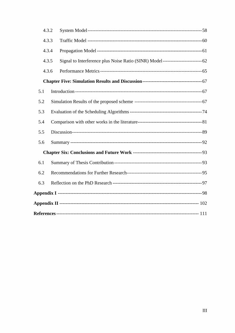
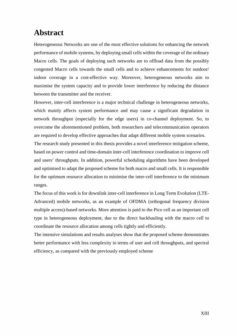
interference, which has a direct impact on mobile network performance. With the increasing
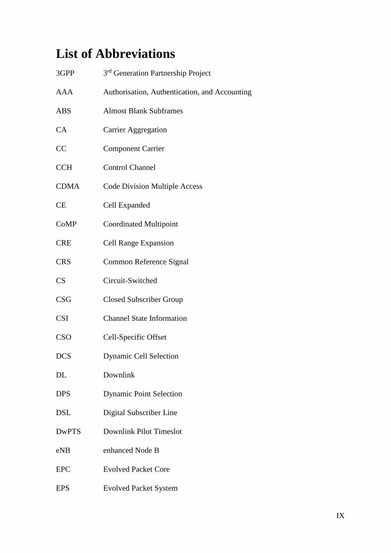
demands for mobile data (as shown in Figure 1-1) and the rapid spread of the smart
applications on the current mobile devices, the limited spectrum became one of the main
constraints in the mobile networks development and supporting higher data rates more
challenging.
Figure 1-1: Predicted Data demands per month over the next years [1]
711
17
24
35
49
0
10
20
30
40
50
60
2016 2017 2018 2019 2020 2021
Exa
byte
s per
Mon
th
Global Mobile Data Traffic, 2016 to 20121
2
As a result, it was essential to move from spectrum efficiency towards the network
efficiency. One of the effective methods in this field is the network densification, where the
same allocated spectrum can be reused in smaller regions to achieve higher spectrum
utilisation. However, inter-cell interference management turns into a more challenging issue,
especially in mobile networks with heterogeneous deployment (HetNets).
1.1 Research Problem
Despite the significant benefits of deploying LTE-Advanced Heterogeneous Networks
(HetNets) to increase the network capacity or to extend the coverage in a cost-effective way,
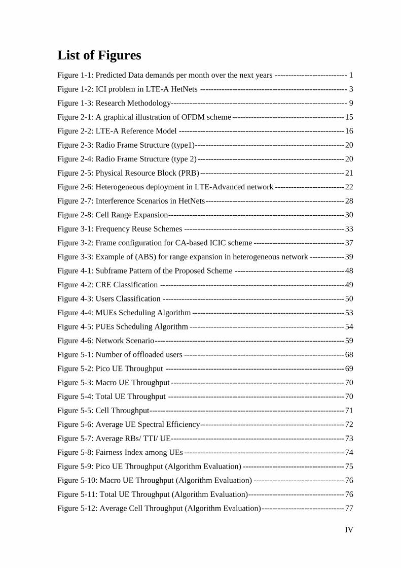
Inter-cell interference (ICI) is one of the largest challenges in such networks when utilising
co-channel deployment. ICI in such deployments has a negative impact on both user and cell
throughputs of all cells in the network. Moreover, traffic balance is directly affected by such
interference. Figure 1-2 illustrates the problem of ICI in LTE-A HetNets, where the
conventional Macro cell is overlaid by Low-Power Cells (LPCs) to increase the network
capacity and to offload more mobile users from the potential congested Macro cell towards
these LPCs.
The conventional cell selection in LTE-A is based on the maximum Reference Signal
Received Power (RSRP) by the User Equipment (UE) from the surrounding cells. However,
due to the transmit power disparity in cells of different classes in the HetNets, most UEs
tends to select the Macro cell as their serving cell as a result of high transmit power, leaving
the Pico cell underutilised. In the same time, theses Macro UEs in the vicinity of the Pico
cells can cause a severe Up Link (UL) interference problem towards the overlaid Pico cells.
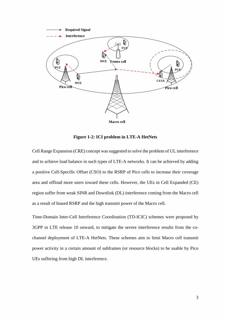
3
Macro cell
PUE
Pico cell
PUE
CEUEMUE
Required Signal
Interference
Pico cell
Femto cell
FUE
MUE
Figure 1-2: ICI problem in LTE-A HetNets
Cell Range Expansion (CRE) concept was suggested to solve the problem of UL interference
and to achieve load balance in such types of LTE-A networks. It can be achieved by adding
a positive Cell-Specific Offset (CSO) to the RSRP of Pico cells to increase their coverage
area and offload more users toward these cells. However, the UEs in Cell Expanded (CE)
region suffer from weak SINR and Downlink (DL) interference coming from the Macro cell
as a result of biased RSRP and the high transmit power of the Macro cell.
Time-Domain Inter-Cell Interference Coordination (TD-ICIC) schemes were proposed by
3GPP in LTE release 10 onward, to mitigate the severe interference results from the co-
channel deployment of LTE-A HetNets. These schemes aim to limit Macro cell transmit
power activity in a certain amount of subframes (or resource blocks) to be usable by Pico
UEs suffering from high DL interference.
4
1.2 Research Motivation
The radio frequency spectrum is a finite and a scarce resource, which should be optimally
utilised when it is being allocated for a certain mobile system. Moreover, the high cost of
spectrum allocation is one of the significant challenges for mobile operators.
The ever growing demands for mobile data and the spread of smart devices entails overriding
the spectrum efficiency limitations by moving towards the network efficiency. The latter
technique mainly utilises network densification to achieve higher performance in mobile
networks by deploying small cells for more spectrum reuse and the lower distance between
the transmitter and the receiver which results in less path loss. HetNets are one of the
essential steps to achieve network densification, by overlaying the traditional Macro cells
with LPCs to improve network capacity while keeping the backwards compatibility for old
mobile users. However, ICI mitigation is a vital issue for co-channel LTE-A HetNets, which
significantly affects the capacity of the network. Most TD-ICIC schemes have a permanent
trade-off between the interference mitigation and the available radio resources for some
cells, which has a negative impact on the overall network performance.
1.3 Aim and Objectives
This research project aims to improve the performance of LTE-A HetNets (in terms of user
and cell throughputs) by mitigating the downlink ICI while achieving a balance between the
performance of cell-edge users of the Pico cell and that of the Macro cell UEs. This aim can
be fulfilled by developing an efficient TD-ICIC scheme with powerful user priority
scheduling algorithms for both Macro and Pico cells, to ensure the optimum resource sharing
among all cells in the network. In this way, the performance of the Macro cell will be
optimised while keeping the performance of Pico cells intact, which in turn results in a higher
network performance.
5
The principal objectives of this thesis can be summarised as follows:
• Study the impact of the interference on the network capacity of LTE-A networks and
explore the current inter-cell interference coordination schemes in LTE-A HetNets.
• Survey the up to date ICIC schemes based on the literature, and investigate the effects
of the Almost Blank Subframes (ABS) and the Reduced-Power Subframes (RPS)
schemes on both radio resources accessibility and the user protection.
• Design a joint configuration utilising both ABS and RPS in the same scheme, to
achieve a balance between the performance of cell-edge users of the LPC and that of
the Macro cell UEs.
• Develop powerful user priority scheduling algorithms for both Macro and Pico cells,
to provide higher scheduling priorities for all vulnerable users (victim users) in the
LTE-A HetNets.
• Design a system model and implement the proposed scheme using DL system-level
simulation, taking into consideration all the required modelling calculations and
other simulation assumptions.
• Test and evaluate the proposed scheme and the user priority scheduling algorithms
according to predefined performance metrics.
• Assess the performance of the final version of this scheme with other TD-ICIC
schemes (ABS and RPS) to test the improvement in network performance against the
other schemes.
1.4 Thesis Contribution
This thesis investigates the interference mitigation in LTE-A HetNets and contributes to
mitigating the inter-cell interference in Macro cell- Pico cell scenarios. Such mitigation
6
provides increased downlink network performance in terms of user and cell throughputs,
which results in total network improvements.
In this thesis, TD-ICIC scheme has been chosen for further improvements as a result of its
higher spectral utilisation by sharing the whole available bandwidth between the Macro cell
and the LPCs, and the capability of employing higher CRE values which in some cases are
necessary to achieve proper load balance in the HetNets. A joint configuration utilising both
ABS and RPS in the same scheme has been proposed to achieve a balance between the
performance of cell-edge users of the LPC and that of the Macro cell UEs. In this way, the
performance of the Macro cell has been optimised while keeping the performance of Pico
cells intact, which in turn results in a higher network performance.
1.5 Research Methodology
This research project adopts a research methodology that mainly relies on evaluation and
improvement of the proposed scheme using Vienna Simulator. This downlink system-level
simulator, which is built on MATLAB, has been modified to support the proposed solution.
Feedback from the supervisor and the examiners at meetings, assessments was also working
as a guideline during the long journey of the PhD research.
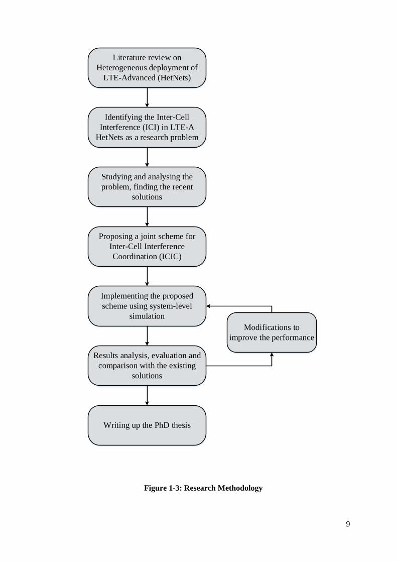
The following research methodology has been adopted in the research program, where the
main steps are illustrated in Figure 1-3:
• Literature review on Heterogeneous deployment of LTE-Advanced (HetNets)
It was the first step of the research program since started the PhD research. After the
intensive discussions with the supervisor about the recent mobile technologies and
their limitations, we have chosen the heterogeneous deployment of LTE-Advanced
as promising systems to satisfy the demands of the next generations of mobile
7
networks. The supervisor created a roadmap for the research and gave correct guides
to choose a critical problem and a novel idea to solve it. Wide literature review on
LTE-Advanced and its heterogeneous deployment have been made, to identify the
recently employed technologies and their limitations. In the same time, up-to date
researches have been investigated.
• Identifying the Inter-Cell Interference (ICI) in LTE-A HetNet as a research
problem
Based on the studied literature, ICI has been identified as a research problem, and
the negative impact of ICI on network capacity and the spectrum utilisation have
been taken into consideration.
In this stage of the investigation, the problem of inter-cell interference in LTE-A
heterogeneous deployment has been recognised as a major issue which severely
affects the performance of the network and limits the benefits of deploying the low-
power cells within the coverage of the conventional macro cells.
• Studying and analysing the problem, finding the recent solutions
To find a novel solution to the research problem, an extensive study was necessary
on the state-of art solutions, analysing their advantages and their limitations. From
the literature, several ICIC schemes were found to solve the problem of interference
in co-channel HetNet, where two of them are working jointly with CRE to provide
inter-cell interference coordination while balancing the load among all cells.
• Proposing a Joint scheme for Inter-Cell Interference Coordination (ICIC)
Several solutions have been suggested by 3GPP and developed by researchers to
mitigate ICI in LTE-A HetNet. However, most of these solutions still have
limitations due to the trade-off in performance between the macro cells and the low-
power cells.
8
As a result, a joint scheme of using both Almost Blank Subframes (ABS) and
Reduced Power Subframes (RPS) has been proposed achieve better results.
Developing powerful scheduling algorithms in both macro cell and low-power cell
is essential to achieve the aim of this interference mitigation scheme.
• Implementing the proposed scheme using system-level simulation
The implementation of the proposed solution includes system modelling and
extensive simulations to get the implementation results. All the system assumptions
and the mathematical equations required for the system model has been determined,
taking into account the interference from the overlaid macro cell and the neighbour
macro cells into account. Unlike some researches in the literature [2], [3], the
interference coming from the adjacent low-power cell has also been taken into
considerations.
• Results analysis, evaluation and comparison with the existing solutions
Simulation results are significant to analyse the performance of the system under this
proposed solution, and taking the necessary measurements which are vital to evaluate
the performance of the system. Subsequently, validation is essential to examine the
applicability of the proposed scheme in practical life. Moreover, comparing these
results with other schemes of the literature is crucial to evaluate the improvement
against the existing ICI schemes.
• Writing up the PhD thesis
It is the final step of our research project after finalising and validating our scheme.
It includes writing up all the required theories from the background to the standards
then presenting the proposed scheme’s results with all analyses and discussions.
Moreover, all conclusions and the expected future work are submitted to the end of
this thesis.
9
Results analysis, evaluation and comparison with the existing
solutions
Writing up the PhD thesis
Implementing the proposed scheme using system-level
simulation
Proposing a joint scheme for Inter-Cell Interference Coordination (ICIC)
Studying and analysing the problem, finding the recent
solutions
Modifications to improve the performance
Identifying the Inter-Cell Interference (ICI) in LTE-A
HetNets as a research problem
Literature review on Heterogeneous deployment of
LTE-Advanced (HetNets)
Figure 1-3: Research Methodology
10
1.6 Thesis Structure
This thesis is organised into six chapters. The current chapter represents a brief introduction
to the PhD research project, which includes the definition of the research problem and the
motivation of choosing to tackle such a problem. In addition, the aim and objectives of this
research have been outlined. Moreover, the methodology followed in this research has been
charted, and all its steps are explained.
Chapter two gives a general overview of the LTE-Advanced network as an example of
OFDMA mobile systems. It describes the network architecture and its related elements in
both homogeneous and heterogeneous deployments. Furthermore, the radio frame structure
and the physical resource block have been explained thoroughly as basic elements in
resource allocation.
As a research problem, inter-cell interference (ICI) has been discussed in chapter three,
reviewing the spectrum assignments in LTE-A and the main frequency reuse techniques used
in homogeneous deployment. The second part of this chapter attempted to classify the ICI
mitigation based on the studied literature, describing various mitigation schemes and
concentrating on the time-domain inter-cell interference coordination scheme as a result of
its higher spectral utilisation and the capability of employing higher CRE values which in
some cases are necessary to achieve the proper load balance in the HetNets. This scheme has
been chosen for further improvements in this thesis. Therefore, some related works in the
literature have been studied and further investigated to give a big picture for the proposed
solution in the next chapter.
Chapter four introduces the proposed joint scheme for inter-cell interference mitigation in
LTE-Advanced HetNets. Moreover, the scheme design and the required scheduling
algorithms for optimum scheme utilisation have been discussed thoroughly for both macro
11
and Pico cells. The next section of this chapter depicts the system model and all simulation
assumptions adopted in the system-level simulation. Furthermore, all the necessary
equations for network modelling has been specified according to the standards.
All simulation results of the proposed scheme and their findings are shown in chapter five.
These results are based on the performance metrics defined in the previous chapter. They
also include the evaluation of the scheduling algorithms and validating the proposed scheme
by comparing it with other works in the literature to highlight the percentage of network
improvements according to the aforementioned metrics. The last section of this chapter
depicts a deep discussion of all simulation results, coming up with a clear picture for the next
chapter.
Finally, the summary of thesis contribution and the outcomes of the research proposal have
been outlined in chapter six. Furthermore, this chapter determines the limitations of this
research and creates recommendations for the future work.
12
2 Chapter Two: Background
2.1 Introduction
Since the first version of mobile communications and the concept of cells in 1947 by Bell
Labs of USA, the requirements for mobile services and associated applications have grown
rapidly to meet the ever-growing demands for more capacity, efficient radio spectrum use,
and higher mobility support.
Packet data using mobile systems started commercially in the mid 1990’s, where General
Packet Radio Services (GPRS) was introduced in the Global System for Mobile
communications (GSM) [4] and in other technologies like PDC standard in Japan. Since that
time, the demands for mobile data has continued to rise exponentially, especially following
the advancements in mobile terminal technologies. As a result, both researchers and
commercial operators have an interest in conducting studies to develop the modern mobile
networks to conform to the state-of art mobile data services, taking into account the potential
constraints and future demands. So far, Long Term Evolution (LTE) mobile network in all
of its releases is considered the most promising system as a part of OFDM technology and
can satisfy the ongoing requirements for more advanced mobile data services. The
subsequent sections in this chapter are going to outline a comprehensive background on the
LTE-Advanced mobile network and its architecture as far as is required for this thesis.
2.2 Long Term Evolution-Advanced (LTE-A)
The ongoing growth of traffic and the future applications required by mobile users has led
the 3rd Generation Partnership Project (3GPP) to develop a new Radio-Access Technology
(RAT). Such new RAT is necessary to support the increasing demands for high-speed
13
applications and advanced multimedia services to all mobile users with higher data rates,
low latency, high mobility, and greater spectral efficiency (about 2-3 times that in HSPA)
[5].
The performance of such (packet optimised systems) has been optimised by employing
enhanced air-interface protocols, and presenting a Multi-Input Multi-Output antenna system
(MIMO), which provides a better quality of received signals and reduces the co-channel
interference, and presents Inter-Cell Interference (ICI) aware techniques.
LTE-A can fulfil Link Adaptation, where the Modulation and Coding Scheme (MCS) can
be changed sensibly per user or frame, according to the channel conditions. In addition,
signal to Interference plus Noise Ratio (SINR) and Hybrid Automatic Repeat ReQuest
(HARQ) function can be utilised by the adaptation algorithm to maximise the throughput in
the time-varying channel.
Unlike the previous mobile systems, two-dimensional resource scheduling (in frequency and
time) can be employed in LTE, which enables multi-users’ transmissions in one time slot.
LTE-Advanced comes to meet the requirements of the 4th Generation by ITU IMT-
Advanced. It provides more enhanced services in the case of mobility and seamless
handover, keeping the interoperability with traditional GSM and CDMA systems. LTE-
Advanced also utilises a layered OFDMA to enhance the whole system performance and
increase the spectrum efficiency.
Moreover, the new technique of Carrier Aggregation (CA) is also used with the layered
OFDMA to combine the Component Carriers (CC's) on the physical layer to provide
backwards compatibility with the LTE Release 8 users together with the LTE-A users.
14
2.2.1 LTE-A Requirements
3GPP has set the requirements for the new LTE system to adapt the modern demands of the
Radio Access Technology (RAT). The most significant requirements are outlined as follows
[6]:
• Scalable architecture with simplified implementation
• Seamless mobility, ensuring the Quality of Service (QoS) for higher speeds
• Reduced delays in both transmission and connection procedures
• Increased user data rates, taking into consideration the cell-edge throughputs
• Enhanced Inter-Cell Interference (ICI) mitigation schemes
• Reduced cost per bit, with a guaranteed spectral efficiency
• Flexible and efficient spectrum usage in all allocated bands
• Optimal power consumption, especially for UEs
Furthermore, Next Generation Mobile Networks (NGMN) alliance of network operators [7]
serves as an additional guide for development and assessment for LTE design. Network
operators’ requirements support the development of the LTE next phase according to IMT-
Advanced requirements of 3GPP.
2.2.2 Multiple Access
Multiple access refers to the way of accessing the available radio resources by the users of
the same mobile network. The most basic types of multiple access methods are the
Frequency Division Multiple Access (FDMA) and the Time Division Multiple Access
(TDMA), which performs the multiple access of mobile users in frequency and time domains
respectively. However, the recent trend of multiple access technique concentrates on
Orthogonal Frequency Division Multiple Access (OFDMA), which offers mutual benefits
15
of both FDMA and TDMA for optimum spectrum utilisation in the next generation of mobile
networks [8].
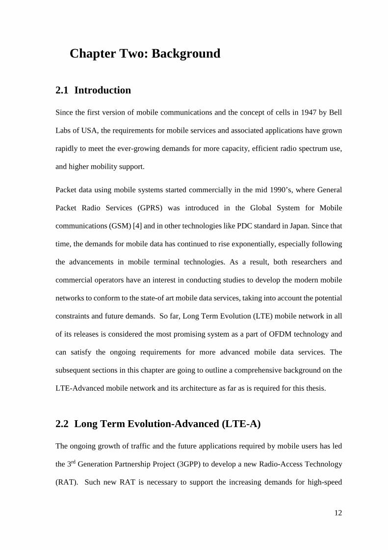
OFDMA is based on OFDM concept [9], which divides the available spectrum into multiple
orthogonal (overlapped) subcarriers (as shown in Figure 2-1) using Discrete Fourier
Transform (DFT) and Fast Fourier Transform (FFT), to be used widely in highly frequency-
time variant wireless radio channels [8].
Channel SC
FDM
OFDM
f
Figure 2-1: A graphical illustration of OFDM scheme
One of the most OFDM distinct features is the flexible and independent operation of the
available spectrum (i.e. offering different channel bandwidths with low complexity at
receiver side). Therefore, OFDMA has become the basic multiple access technique for LTE-
A and the next generations [10].
2.2.3 LTE-A Architecture
LTE-A architecture is designed to introduce a packet-switched (PS) network, which supports
all kinds of services including a voice in an easy way, with a minimum latency (as RNC is
not included in the data path), seamless mobility and better Quality of Service (QoS).
16
Therefore, all the services that were traditionally Circuit Switched (CS) are now handled by
IP Multimedia Subsystem (IMS) network in LTE.
The LTE architecture, which is called Evolved Packet System (EPS), comprises two parts:
the radio part (E-UTRAN), and the network part (EPC) [11], [12].
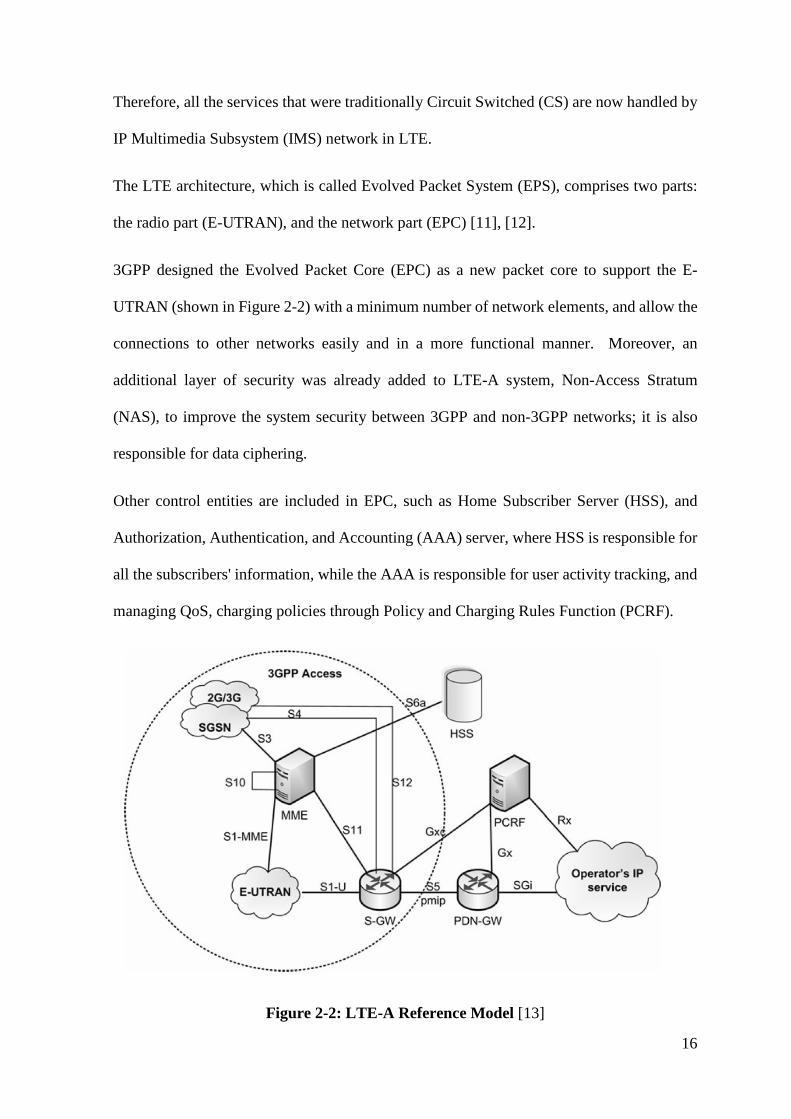
3GPP designed the Evolved Packet Core (EPC) as a new packet core to support the E-
UTRAN (shown in Figure 2-2) with a minimum number of network elements, and allow the
connections to other networks easily and in a more functional manner. Moreover, an
additional layer of security was already added to LTE-A system, Non-Access Stratum
(NAS), to improve the system security between 3GPP and non-3GPP networks; it is also
responsible for data ciphering.
Other control entities are included in EPC, such as Home Subscriber Server (HSS), and
Authorization, Authentication, and Accounting (AAA) server, where HSS is responsible for
all the subscribers' information, while the AAA is responsible for user activity tracking, and
managing QoS, charging policies through Policy and Charging Rules Function (PCRF).
Figure 2-2: LTE-A Reference Model [13]
17
2.2.4 Network Elements
The distinct architecture of LTE-A introduces new control-plane elements to the EPC:
• Mobility Management Entity (MME)
A new control-plane Mobility Management Entity (MME) is responsible for new protocol
implementation in LTE-A. MME communicates with the HSS for retrieving subscriber
information, and with the serving gateway to establish and release the EPS bearers. It
communicates with eNB over the S1 interface and supports mobility between 3GPP access
networks via an S3 interface with the Serving GPRS Support Node (SGSN) [14].
• Serving Gateway (S-GW)
The main function of the S-GW is packet routing in the LTE-A network and packet buffering
when paging a UE. It also acts as a local mobility anchor in case of inter-eNB Handover
(HO). Furthermore, it communicates with the PCRF entity for charging control and lawful
interception.
• Packet Data Network Gateway (PDN-GW)
PDN-GW is considered the default router to connect the UE of the network to an external
Packet Data Network (PDN) such as internet and IMS. It is responsible for UE IP allocation
as an LTE-A user can have several IP addresses with different PDNs. It also performs QoS
enforcement of the IP (Internet Protocol) packet flow to the UE [15].
• Evolved Node-B (eNB)
The traditional base station in LTE-A is known as Evolved Node-B (eNB). Unlike the
conventional Node-B, its function includes the protocol implementation, which is
implemented by RNC. An eNB can perform admission control and Radio Resources
Management (RRM). Also, it is responsible for providing scheduling, traffic load balance,
and interference management [11], [12].
18
In light of this, the protocols and functions (PDCP, RLC, and RRC functions) were
terminated in RNC, but now they are terminated at eNB itself, which reduces the latency and
eliminates the role of the traditional existence of RNC [6].
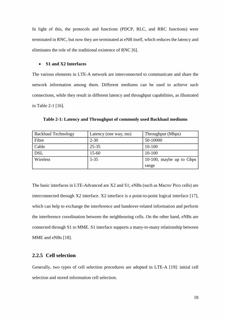
• S1 and X2 Interfaces
The various elements in LTE-A network are interconnected to communicate and share the
network information among them. Different mediums can be used to achieve such
connections, while they result in different latency and throughput capabilities, as illustrated
in Table 2-1 [16].
Table 2-1: Latency and Throughput of commonly used Backhaul mediums
Backhaul Technology Latency (one way, ms) Throughput (Mbps) Fibre 2-30 50-10000 Cable 25-35 10-100 DSL 15-60 10-100 Wireless 5-35 10-100, maybe up to Gbps
range
The basic interfaces in LTE-Advanced are X2 and S1; eNBs (such as Macro/ Pico cells) are
interconnected through X2 interface. X2 interface is a point-to-point logical interface [17],
which can help to exchange the interference and handover-related information and perform
the interference coordination between the neighbouring cells. On the other hand, eNBs are
connected through S1 to MME. S1 interface supports a many-to-many relationship between
MME and eNBs [18].
2.2.5 Cell selection
Generally, two types of cell selection procedures are adopted in LTE-A [19]: initial cell
selection and stored information cell selection.
19
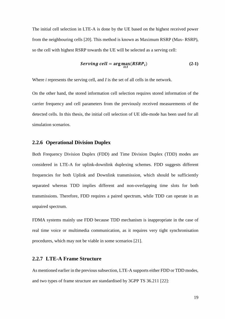
The initial cell selection in LTE-A is done by the UE based on the highest received power
from the neighbouring cells [20]. This method is known as Maximum RSRP (Max- RSRP),
so the cell with highest RSRP towards the UE will be selected as a serving cell:
𝑺𝑺𝑺𝑺𝑺𝑺𝑺𝑺𝑺𝑺𝑺𝑺𝑺𝑺 𝒄𝒄𝑺𝑺𝒄𝒄𝒄𝒄 = 𝐚𝐚𝐚𝐚𝐚𝐚𝐦𝐦𝐚𝐚𝐦𝐦𝑺𝑺∈𝑰𝑰
(𝑹𝑹𝑺𝑺𝑹𝑹𝑹𝑹𝑺𝑺) (2-1)
Where i represents the serving cell, and I is the set of all cells in the network.
On the other hand, the stored information cell selection requires stored information of the
carrier frequency and cell parameters from the previously received measurements of the
detected cells. In this thesis, the initial cell selection of UE idle-mode has been used for all
simulation scenarios.
2.2.6 Operational Division Duplex
Both Frequency Division Duplex (FDD) and Time Division Duplex (TDD) modes are
considered in LTE-A for uplink-downlink duplexing schemes. FDD suggests different
frequencies for both Uplink and Downlink transmission, which should be sufficiently
separated whereas TDD implies different and non-overlapping time slots for both
transmissions. Therefore, FDD requires a paired spectrum, while TDD can operate in an
unpaired spectrum.
FDMA systems mainly use FDD because TDD mechanism is inappropriate in the case of
real time voice or multimedia communication, as it requires very tight synchronisation
procedures, which may not be viable in some scenarios [21].
2.2.7 LTE-A Frame Structure
As mentioned earlier in the previous subsection, LTE-A supports either FDD or TDD modes,
and two types of frame structure are standardised by 3GPP TS 36.211 [22]:
20
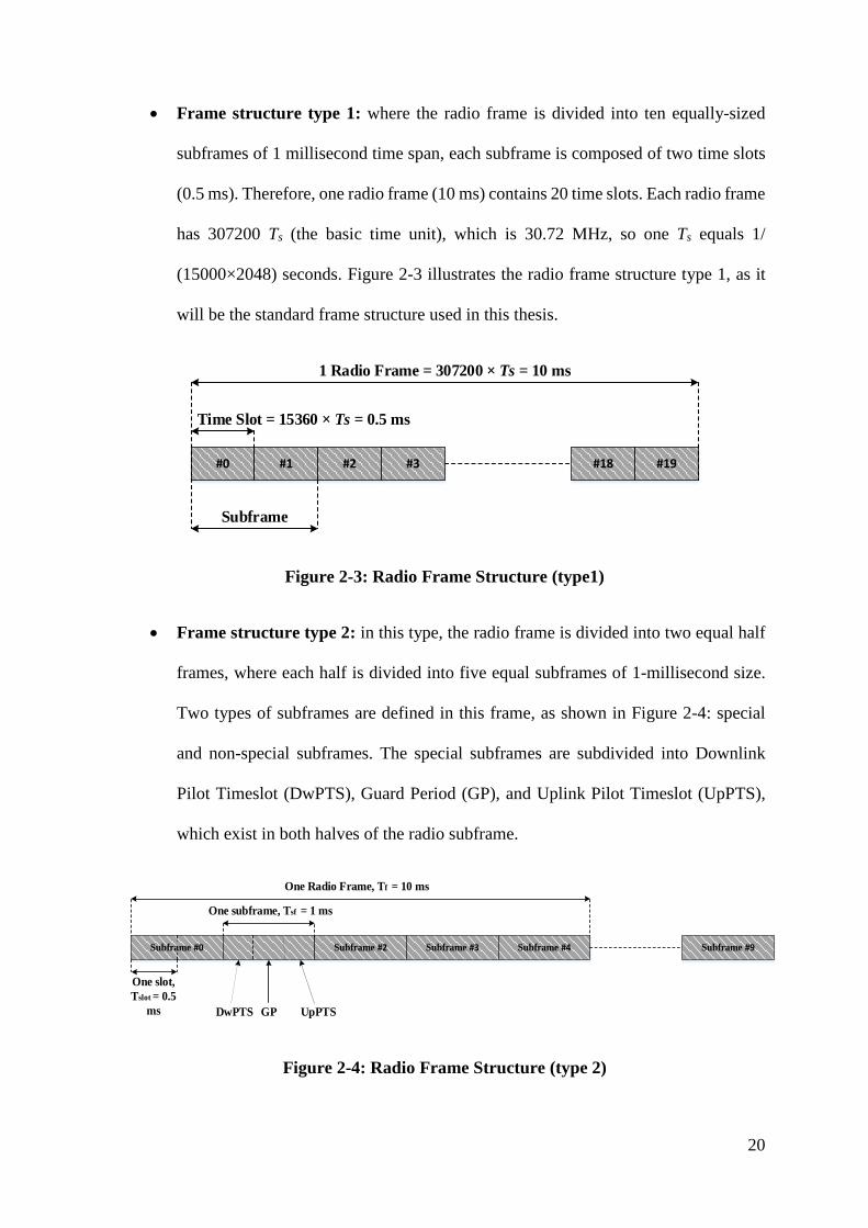
• Frame structure type 1: where the radio frame is divided into ten equally-sized
subframes of 1 millisecond time span, each subframe is composed of two time slots
(0.5 ms). Therefore, one radio frame (10 ms) contains 20 time slots. Each radio frame
has 307200 Ts (the basic time unit), which is 30.72 MHz, so one Ts equals 1/
(15000×2048) seconds. Figure 2-3 illustrates the radio frame structure type 1, as it
will be the standard frame structure used in this thesis.
#0 #1 #2 #3 #18 #19
Subframe
Time Slot = 15360 × Ts = 0.5 ms
1 Radio Frame = 307200 × Ts = 10 ms
Figure 2-3: Radio Frame Structure (type1)
• Frame structure type 2: in this type, the radio frame is divided into two equal half
frames, where each half is divided into five equal subframes of 1-millisecond size.
Two types of subframes are defined in this frame, as shown in Figure 2-4: special
and non-special subframes. The special subframes are subdivided into Downlink
Pilot Timeslot (DwPTS), Guard Period (GP), and Uplink Pilot Timeslot (UpPTS),
which exist in both halves of the radio subframe.
Subframe #0 Subframe #2 Subframe #3 Subframe #4 Subframe #9
One slot, Tslot = 0.5
ms
One subframe, Tsf = 1 ms
DwPTS GP UpPTS
One Radio Frame, Tf = 10 ms
Figure 2-4: Radio Frame Structure (type 2)
21
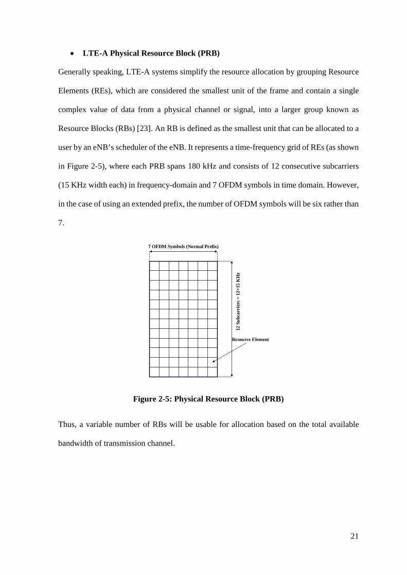
• LTE-A Physical Resource Block (PRB)
Generally speaking, LTE-A systems simplify the resource allocation by grouping Resource
Elements (REs), which are considered the smallest unit of the frame and contain a single
complex value of data from a physical channel or signal, into a larger group known as
Resource Blocks (RBs) [23]. An RB is defined as the smallest unit that can be allocated to a
user by an eNB’s scheduler of the eNB. It represents a time-frequency grid of REs (as shown
in Figure 2-5), where each PRB spans 180 kHz and consists of 12 consecutive subcarriers
(15 KHz width each) in frequency-domain and 7 OFDM symbols in time domain. However,
in the case of using an extended prefix, the number of OFDM symbols will be six rather than
7.
7 OFDM Symbols (Normal Prefix)
12 S
ubca
rrie
rs =
12×
15 K
Hz
Resource Element
Figure 2-5: Physical Resource Block (PRB)
Thus, a variable number of RBs will be usable for allocation based on the total available
bandwidth of transmission channel.
22
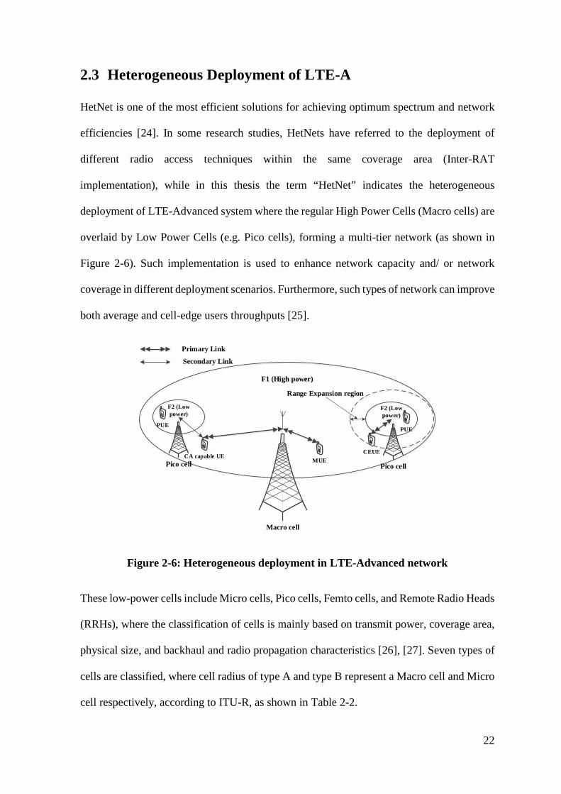
2.3 Heterogeneous Deployment of LTE-A
HetNet is one of the most efficient solutions for achieving optimum spectrum and network
efficiencies [24]. In some research studies, HetNets have referred to the deployment of
different radio access techniques within the same coverage area (Inter-RAT
implementation), while in this thesis the term “HetNet” indicates the heterogeneous
deployment of LTE-Advanced system where the regular High Power Cells (Macro cells) are
overlaid by Low Power Cells (e.g. Pico cells), forming a multi-tier network (as shown in
Figure 2-6). Such implementation is used to enhance network capacity and/ or network
coverage in different deployment scenarios. Furthermore, such types of network can improve
both average and cell-edge users throughputs [25].
F1 (High power)
Macro cell
PUE
F2 (Low power)
F2 (Low power)
Pico cell
PUE
CEUECA capable UE
Primary Link
Secondary Link
Pico cell
Range Expansion region
MUE
Figure 2-6: Heterogeneous deployment in LTE-Advanced network
These low-power cells include Micro cells, Pico cells, Femto cells, and Remote Radio Heads
(RRHs), where the classification of cells is mainly based on transmit power, coverage area,
physical size, and backhaul and radio propagation characteristics [26], [27]. Seven types of
cells are classified, where cell radius of type A and type B represent a Macro cell and Micro
cell respectively, according to ITU-R, as shown in Table 2-2.
23
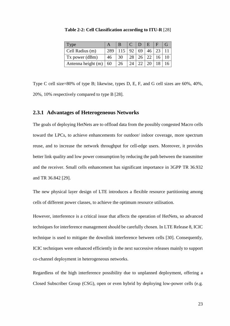
Table 2-2: Cell Classification according to ITU-R [28]
Type A B C D E F G Cell Radius (m) 289 115 92 69 46 23 11 Tx power (dBm) 46 30 28 26 22 16 10 Antenna height (m) 60 26 24 22 20 18 16
Type C cell size=80% of type B; likewise, types D, E, F, and G cell sizes are 60%, 40%,
20%, 10% respectively compared to type B [28].
2.3.1 Advantages of Heterogeneous Networks
The goals of deploying HetNets are to offload data from the possibly congested Macro cells
toward the LPCs, to achieve enhancements for outdoor/ indoor coverage, more spectrum
reuse, and to increase the network throughput for cell-edge users. Moreover, it provides
better link quality and low power consumption by reducing the path between the transmitter
and the receiver. Small cells enhancement has significant importance in 3GPP TR 36.932
and TR 36.842 [29].
The new physical layer design of LTE introduces a flexible resource partitioning among
cells of different power classes, to achieve the optimum resource utilisation.
However, interference is a critical issue that affects the operation of HetNets, so advanced
techniques for interference management should be carefully chosen. In LTE Release 8, ICIC
technique is used to mitigate the downlink interference between cells [30]. Consequently,
ICIC techniques were enhanced efficiently in the next successive releases mainly to support
co-channel deployment in heterogeneous networks.
Regardless of the high interference possibility due to unplanned deployment, offering a
Closed Subscriber Group (CSG), open or even hybrid by deploying low-power cells (e.g.
24
Femto cells) to cover the gaps between cells and to provide better coverage for a certain
number of indoor users is one of the applied solutions [31].
Since there is no X2 interface defined between Macro/ Femto cells to enable interference
coordination techniques, interference management for co-channel deployment can be done
through Operation and Maintenance (OAM) and power control techniques (in Release 10)
to minimise the link failure due to interference.
Studies on Release 12 and onward focus on network densification to meet the increasing
demands for high-speed applications without affecting the scarce spectrum. In turn, such
deployments require the development of the number of radio and protocols solutions to
achieve that gain [27].
2.3.2 Carrier Frequency Allocation
Due to some regulatory limitations and heavy usage of the recent spectrum, most
heterogeneous deployments focus on same-frequency operations (intra-frequency) wherein
Macro/ low-power cell layers share the same carrier frequency(s).
3GPP has identified Release 12 requirements in TR 36.932, where different scenarios for
heterogeneous deployment are suggested:
I. Macro/ low-power cells share the same carrier frequencies (Intra-frequency)
[32], [33].
II. Macro/ low-power cells use different carrier frequencies (Inter-frequency).
III. Deployment of only low-power cells sharing one or more carrier frequencies.
Thus, using different carrier frequencies for both layers (Macro/ low-power cells) has less
complexity as it does not require a centralised architecture or tight coordination between
25
layers. However, such enhancement comes with the price of multiple carriers’ usage, and
Inter-frequency handover, which consumes more time and terminal battery life [34], [35].
On the other hand, Intra-frequency deployment is spectrum efficient since it can provide
better resources partitioning [32] but it is more challenging to mitigate the cross-tier
interference and mobility management between cells using the same carrier frequencies
(especially in CE region) [36]. These two challenges require a robust UE solution to
overcome such interference in heterogeneous deployment.
The availability of higher frequency bands (e.g. 3.5 GHz) can support better spectrum usage
by using separate spectrums for each layer, which leads to minimised interference between
the two network layers. Frequency-separated deployments can be used to exploit both duplex
schemes (FDD/TDD) to achieve better performance [37]. Dynamic TDD is possibly
beneficial in local area coverage, where the network can dynamically choose between UL
and DL according to the instantaneous needs [38].
2.3.3 HetNet Components
HetNets follow the same architecture of any LTE-A network (as described in section LTE-
A Architecture). However, several types of cells with different characteristics could be
deployed in such networks, forming a multi-tier network:
• Macro cells: refer to the conventional eNBs, which are installed by operators to
provide open access to all users subscribed to the network. This type of cell has a
high transmit power of up to 46 dBm and covers a wide area of a few kilometres. It
is utilised to serve thousands of users with a minimum guaranteed data rate and
tolerable delay.
• Pico cells: they are fully-fledged eNBs with low transmit power (23-30 dBm),
deployed by operators to improve network capacity/ coverage for either indoor or
26
outdoor environment [39]. They provide open access for all users of the network
when Macro cell capabilities are insufficient for dense areas.
• Femto cells: this term describes the low-power cells (up to 23 dBm) used to provide
unplanned deployment by users for indoor environments (e.g. office, mall, etc.). This
type of cell features some access restrictions for certain users, as they are deployed
by the customers, and they utilise other types of backhauling (e.g. DSL) to reach the
mobile network.
• Relay nodes: refer to the access points used to route the data from Macro cells to the
users to extend the coverage in new areas. They use wireless backhaul to connect the
Macro cells and have limited capabilities as compared with other low-power cells.
2.3.4 Technical Challenges in HetNets
As a result of different power characteristics of cells (e.g. transmit power, power control
settings) [40], HetNet has several challenges, which have significant impacts on the potential
achieved performance of this type of deployment. Based on the literature, the most major
challenges can be outlined as follows:
• Imbalanced coverage between UL/ DL: transmit power disparity between the
Macro cell and low-power cell is one of the biggest problems in HetNets [40],
where the best DL cell and the best UL cell for a certain UE may be different,
as a result of different output power for each cell. Moreover, each cell may
have a different UL power control setting. Due to a larger transmit power of
Macro cell, handover boundaries are shifted closer to the low-power cell,
which can lead to severe UL interference as a result of Macro user impact on
low-power cell [30].
27
• More frequent handover due to smaller footprints of low-power cells, which
leads to more signalling overhead. Signalling overhead could be minimised
by using an RRC inactivity timer, where RRC connection is released by the
base station when there is no data activity, which leads to less handover
signalling overhead. Furthermore, it can be reduced when releasing inactive
UEs during the handover process. A shorter RRC inactivity timer leads to
less handover signalling overhead compared to connection setup overhead
[41].
• Interference from Macro cell to low-power cells which causes
underutilisation in low-power cells (which is the most effective challenge for
many deployments) [42].
• Cell selection (especially for UE in CE region).
• UL interference due to shifted handover boundaries toward the low-power
cells.
• Mobility robustness: due to the more frequent handover, heterogeneous
deployment leads to more handover failure (HOF), which has a negative
impact on the Quality of Service.
• Backhauling limitations between the Macro cell and low-power cell (e.g.
there is no direct interface between the Macro cell and Femto cell).
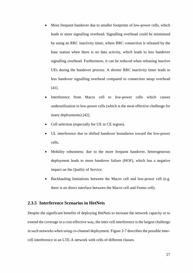
2.3.5 Interference Scenarios in HetNets
Despite the significant benefits of deploying HetNets to increase the network capacity or to
extend the coverage in a cost-effective way, the inter-cell interference is the largest challenge
in such networks when using co-channel deployment. Figure 2-7 describes the possible inter-
cell interference in an LTE-A network with cells of different classes.
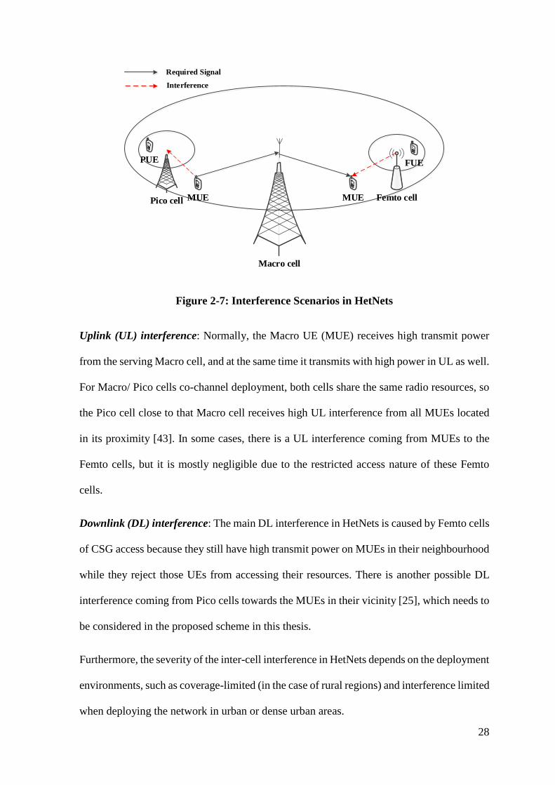
28
Macro cell
PUE
Femto cellPico cell
FUE
MUEMUE
Required Signal
Interference
Figure 2-7: Interference Scenarios in HetNets
Uplink (UL) interference: Normally, the Macro UE (MUE) receives high transmit power
from the serving Macro cell, and at the same time it transmits with high power in UL as well.
For Macro/ Pico cells co-channel deployment, both cells share the same radio resources, so
the Pico cell close to that Macro cell receives high UL interference from all MUEs located
in its proximity [43]. In some cases, there is a UL interference coming from MUEs to the
Femto cells, but it is mostly negligible due to the restricted access nature of these Femto
cells.
Downlink (DL) interference: The main DL interference in HetNets is caused by Femto cells
of CSG access because they still have high transmit power on MUEs in their neighbourhood
while they reject those UEs from accessing their resources. There is another possible DL
interference coming from Pico cells towards the MUEs in their vicinity [25], which needs to
be considered in the proposed scheme in this thesis.
Furthermore, the severity of the inter-cell interference in HetNets depends on the deployment
environments, such as coverage-limited (in the case of rural regions) and interference limited
when deploying the network in urban or dense urban areas.
29
2.3.6 Transmission Mode (CSG, OSG, HSG)
Several access modes are identified in LTE-A HetNets to regulate the UEs access to the
network:
• Closed Subscriber Group (CSG): It is the most restricted access mode, which is
mainly defined for the Femto cells. In this mode, only predefined UEs have the
exclusive permission to connect the Femto cell [44].
• Open Subscriber Group (OSG): Where all UEs in the network has the right to
connect the open access cells.
• Hybrid Subscriber Group (HSG): In this mode, the highest priority access is for the
predefined UEs; subsequently, the rest of the UEs can access that cell according to
the available resources [45], [46].
2.3.7 Cell Range Expansion (CRE)
Conventionally, cell selection in LTE systems is done by a UE based on Maximum RSRP
(Max. RSRP) among several surrounding cells [47]. As a result of different power
characteristics in heterogeneous networks, this results in less offloaded users from Macro to
the low-power cell, which leads to load imbalance in HetNets.
CRE is one of the recent solutions to solve the problem of UL interference. In this concept,
the low-power cell RSRP is positively biased by a CSO, as shown in Figure 2-8 to increase
their DL coverage [2], and to overcome the situation of fewer users offloaded from Macro
cell towards the low-power cell [44], [45].
The bias value refers to a threshold that triggers handover between two cells. A positive bias
means that UE will be handed over to the low-power cell when the difference in signal
strength from the Macro cell and low-power cell drops below a bias value.
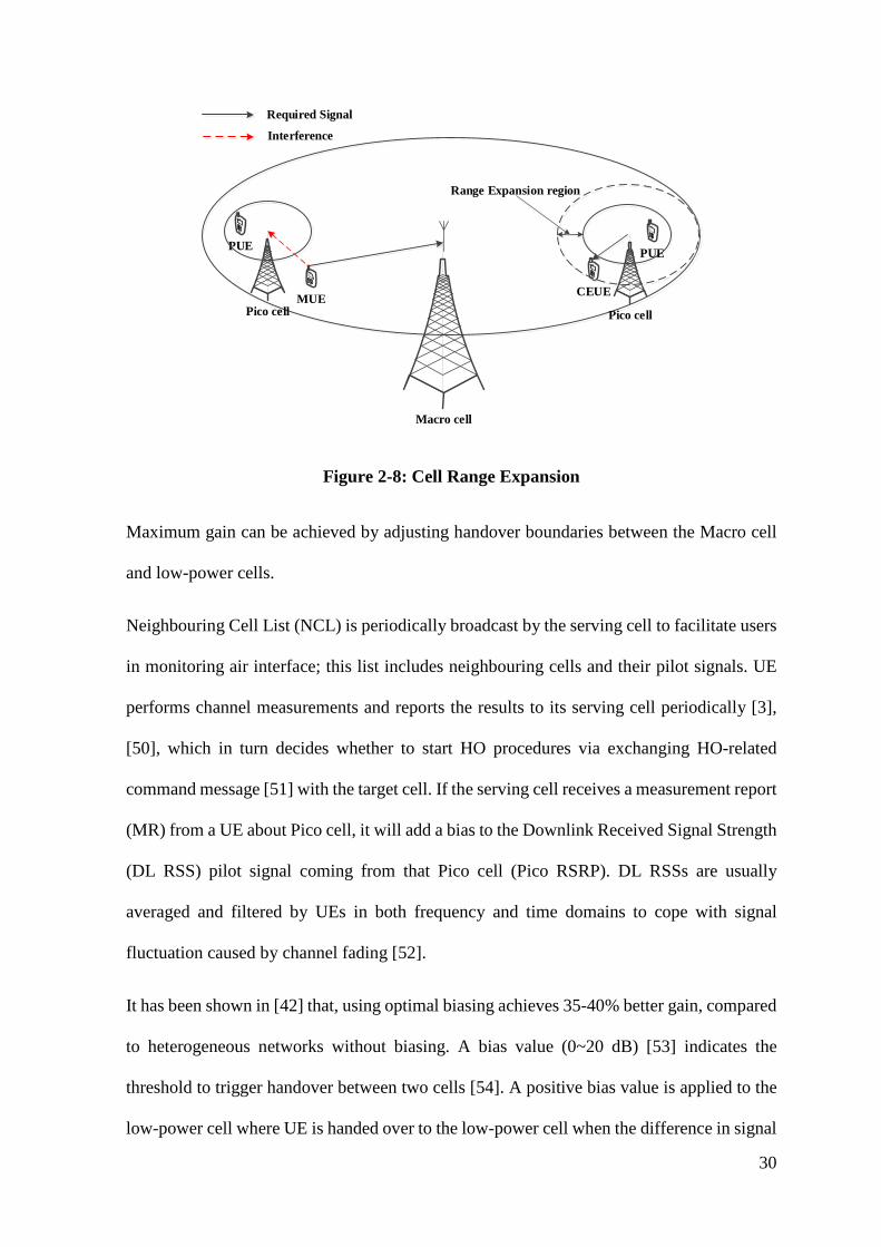
30
Macro cell
PUE
Pico cell
PUE
CEUEMUE
Required Signal
Interference
Pico cell
Range Expansion region
Figure 2-8: Cell Range Expansion
Maximum gain can be achieved by adjusting handover boundaries between the Macro cell
and low-power cells.
Neighbouring Cell List (NCL) is periodically broadcast by the serving cell to facilitate users
in monitoring air interface; this list includes neighbouring cells and their pilot signals. UE
performs channel measurements and reports the results to its serving cell periodically [3],
[50], which in turn decides whether to start HO procedures via exchanging HO-related
command message [51] with the target cell. If the serving cell receives a measurement report
(MR) from a UE about Pico cell, it will add a bias to the Downlink Received Signal Strength
(DL RSS) pilot signal coming from that Pico cell (Pico RSRP). DL RSSs are usually
averaged and filtered by UEs in both frequency and time domains to cope with signal
fluctuation caused by channel fading [52].
It has been shown in [42] that, using optimal biasing achieves 35-40% better gain, compared
to heterogeneous networks without biasing. A bias value (0~20 dB) [53] indicates the
threshold to trigger handover between two cells [54]. A positive bias value is applied to the
low-power cell where UE is handed over to the low-power cell when the difference in signal
31
strength between Macro/ low-power cell in CE region drops less than this bias value. “CRE
may be useful for the Macro cell to reduce the number of handovers” [35]. Employing a
positive bias is necessary to improve load balance in HetNet [48].
However, fixed bias value could not adapt the change in user distribution over time, so it is
important to dynamically adjust the RE region according to the system performance
feedback, to achieve the optimum load balancing and better cell-edge user throughput while
maintaining the overall cell performance.
2.4 Summary
This chapter gives a background to LTE-Advanced as an example of OFDM networks,
describing the main features and requirements of such networks. LTE-Advanced
architecture, network elements, and the frequency planning have been explained in relation
to the purpose of this thesis. Both operation duplex division schemes (FDD, TDD) have been
summarised, giving the features of FDD to provide a more realistic implementation in the
case of real-time voice and multimedia services over the TDD scheme. Their significance in
Resource Allocation (RA), especially in co-channel deployment, radio frame and the
physical resource block structures, has been discussed thoroughly.
The second part of this chapter describes the heterogeneous deployment of LTE-Advanced,
spotting the main features and the technical challenges of such deployment. Inter-cell
interference has been highlighted as the main problem in HetNets, by describing the possible
interference scenarios and the other literature on this issue. Finally, CRE concept has been
outlined due to its impact on the proposed scheme for inter-cell interference mitigation of
LTE-Advanced HetNets.
32
3 Chapter Three: Interference Management in
LTE-Advanced
3.1 Introduction
Two main types of interference management have been highlighted in most mobile systems:
Interference cancellation [55] and interference mitigation [56]. The first type of interference
management is implemented on the received signals by subtracting the interfering signals to
allow only the required signals from being decoded successfully. Despite the fact of
achieving high capacity, the implementation of interference cancellation in mobile systems
may result in high process complexity to estimate the interfering signals [57]. As a result,
interference mitigation has gained more attention to prevent the interference before its
occurrence. This mitigation can always be achieved by frequency planning, power control,
and antenna planning. Mobile networks operators have several spectrum bands, which
should be carefully utilised to achieve higher capacity while maintaining the lowest levels
of interference.
3.2 Spectrum Assignment
The coverage area of any mobile network is required to serve high volumes of users at the
same time. This issue leads to significant limitations in base station capabilities and the
requirements for more carrier frequencies to adapt to such scenarios, which is impractical
due to technical constraints and the expensive cost of the radio spectrum. Therefore, the
cellular concept [58], [59] has been introduced to expand the coverage area of the network
and to increase the number of accessible channels. In this concept, several base stations are
utilised to cover the entire coverage using frequency reuse schemes to increase the network

33
capacity while avoiding the unnecessary interference resulting from the frequency reuse.
Each set of base stations (cluster) should be allocated a certain number of radio channels,
where any adjacent base stations must utilise a different set of channels to avoid any
excessive interference, especially in cell-edges. In this way, the same set of radio channels
can be reused several times in other clusters safely. Several frequency reuse schemes have
been adopted, as shown in Figure 3-1:
F1
F1
F1
F3
F1
F2
F1
F1
F1
F1
F1
F1
FrequencyPo
wer
Frequency
Pow
er
Frequency
Pow
er(A) FR-1
(B) FR-3
(C) FFR
Figure 3-1: Frequency Reuse Schemes
3.2.1 Frequency Reuse
The simplest type of frequency reuse scheme is reuse factor-1, where the available
bandwidth can be freely reused in each cell of the network without any restrictions. Despite
the high potential throughput, the inter-cell interference in such a scheme is more critical,
especially for cell-edge users [18]. In return, the reuse factor-3 results in better inter-cell
34
interference mitigation with the price of less available capacity for each cell. In this scheme,
the total bandwidth is divided into three orthogonal (non-overlapped) sub-bands to be
allocated for adjacent cells safely. However, poor throughput may be achieved as one-third
of the available bandwidth will be accessible by each cell [60].
3.2.2 Fractional Frequency Reuse (FFR)
As a trade-off between throughput and interference in the schemes mentioned above,
Fractional Frequency Reuse (FFR) has been introduced to make a compromised solution
[61], [62].
Inherently, UEs in cell-centres experience high signal quality and they are more protected
against the interference resulting from neighbouring cells. On the other hand, cell-edge UEs
are prone to higher interference and receive a degraded signal due to their far location to
their serving cell. As a result, the cell-centre of every cell in the network employs frequency
reuse factor-1 with lower transmit power, while the cell-edges operate frequency reuse
factor-3 with full transmit power [60], [31]. In addition, other types of frequency reuse
schemes are employed in Homogeneous networks, but they are beyond the scope of this
thesis.
3.3 Inter-Cell Interference Mitigation in Heterogeneous
Deployment
As a promising implementation, HetNets face several challenges that affect the performance
of such networks (e.g. load balance, Inter-cell Interference, cell selection, mobility
robustness, etc.), so many solutions have been introduced through the successive releases of
LTE to overcome the aforementioned challenges.
35
Several spectrum assignments have been adopted in heterogeneous networks for efficient
spectrum utilisation. One of these assignments is the fully-dedicated spectrum, where a
different set of spectrum bands are assigned for the Macro cells and low-power cell. In this
approach, the cross-tier interference is totally avoided. However, the limited spectrum share
for each tier results in low spectrum efficiency which has a negative impact on the network
performance. Therefore, shared spectrum (co-channel deployment) can offer higher
spectrum utilisation but with the cost of high interference possibilities that necessitate a well-
planned inter-cell interference coordination in such implementations. The next subsections
will discuss some of the most efficient techniques to mitigate the ICI problem based on
literature.
3.3.1 Power-Domain Inter-Cell Interference Coordination (PD-ICIC)
UEs measure the DL Received Signal Strength (RSS) of the pilot signals continuously of the
surround cells to choose the serving cell. Noting that, the pilot signal is usually transmitted
at a fixed power and it implies the Physical Cell Identities (PCIs). Moreover, the NCL, which
contains the list of neighbour cells and the pilot signals are broadcast by the serving cell
periodically. Thus, UE performs the channel measurements and report them back to its
serving cell, which is significant for making a handover decision. In this scheme [2], a
cooperative algorithm is required to make a decision for the maximum power that every
Macro cell can apply on each RB used by cell-edge UEs to provide the necessary SINR for
these UEs. UE calculates the maximum tolerable ICI, target SINR, and the noise power, to
measure the maximum power and the RB index that can be used by the neighbour cell. In
this way, Macro cells should allocate RB powers according to the power constraints derived
from previous steps to mitigate the potential interference toward the cell-edge UEs of the
neighbour cells. Such scheme requires a scheduling priority as there is independent power
allocation for the available RBs. One of the main challenges in this scheme is how to
36
maintain the required throughput of all attached UEs when using different power allocation
on some RBs [63].
3.3.2 Coordinated Multipoint (CoMP)
It is a technique developed by 3GPP for LTE-Advanced (Release 11 and onward) to send
and receive data to/ from several points to ensure the optimum performance regarding cell-
edge and system throughputs [64]. The primary difference between the standard MIMO and
CoMP is that the transmitters in the latter are not physically co-located.
The idea behind this technique is to enable dynamic coordination of transmission and
reception over several base stations, to turn the Inter-Cell Interference into a useful signal,
especially at cell borders where the problem of ICI increases [65]–[67]. Several types of
CoMP have been introduced, which are defined for the downlink as follows:
• Joint Transmission (JT): This is a type of spatial multiplexing when more than one
point cooperate so that UE data is transmitted simultaneously from several points.
• Dynamic Point Selection (DPS): In this case, all points share the UE data, while
only one point is chosen to transmit this data according to the coordination of all
surrounding points.
Other types of coordinated scheduling and beamforming are also defined where UE data is
only available and transmitted from a single point, but all points coordinate their scheduling
decisions and resource allocation inside the cooperating set.
Although CoMP has no specific support in LTE-A (Release 10) of 3GPP standards, some
schemes can be implemented in this release, and simple upgrade is needed when the
standardisation will be agreed in future releases [27]. Furthermore, a tight coordination
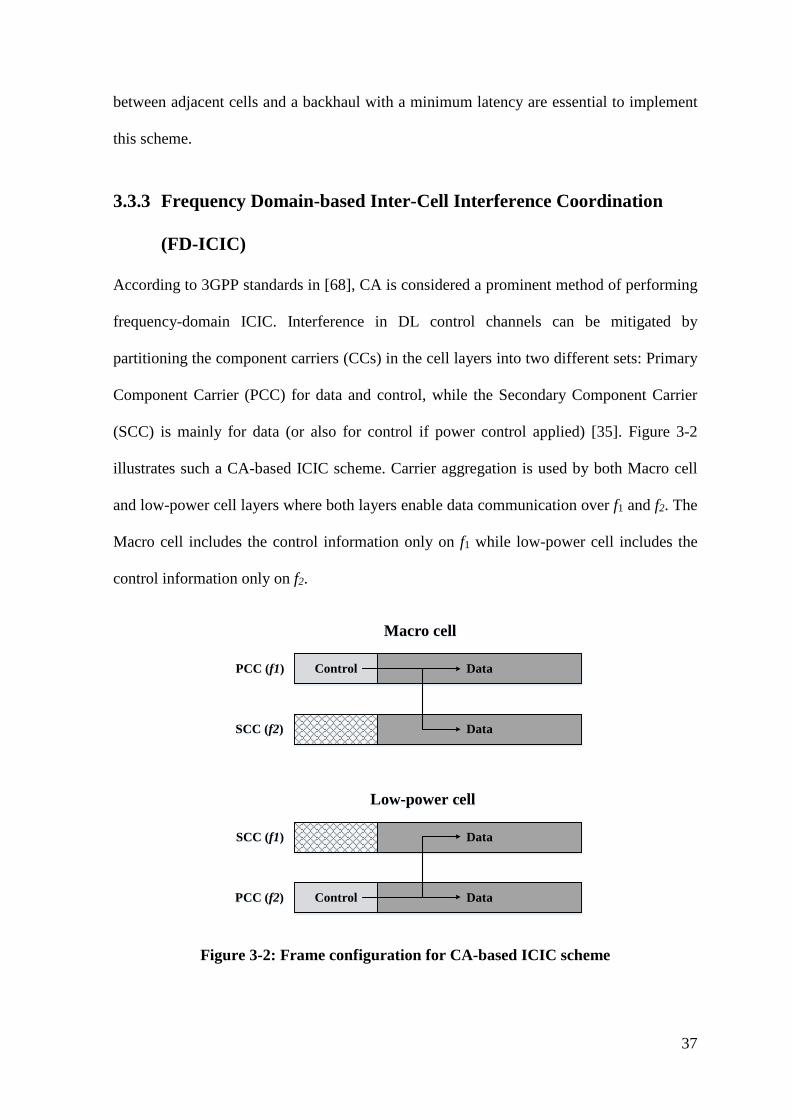
37
between adjacent cells and a backhaul with a minimum latency are essential to implement
this scheme.
3.3.3 Frequency Domain-based Inter-Cell Interference Coordination
(FD-ICIC)
According to 3GPP standards in [68], CA is considered a prominent method of performing
frequency-domain ICIC. Interference in DL control channels can be mitigated by
partitioning the component carriers (CCs) in the cell layers into two different sets: Primary
Component Carrier (PCC) for data and control, while the Secondary Component Carrier
(SCC) is mainly for data (or also for control if power control applied) [35]. Figure 3-2
illustrates such a CA-based ICIC scheme. Carrier aggregation is used by both Macro cell
and low-power cell layers where both layers enable data communication over f1 and f2. The
Macro cell includes the control information only on f1 while low-power cell includes the
control information only on f2.
DataControl
Data
PCC (f1)
SCC (f2)
Macro cell
Data
DataControl
SCC (f1)
PCC (f2)
Low-power cell
Figure 3-2: Frame configuration for CA-based ICIC scheme
38
By using this simple mechanism, the control signalling for the different layers is separated.
In such a case, the Macro cell adopts the carrier f1 as the PCC while applying power control
schemes on carrier f2 to minimise interference on low-power tier. Similarly, low-power cell
utilises f2 as the primary carrier and applies power control schemes on f1.
Most researchers focus on Control Channel (CCH) interference [69], while few papers
concentrate on both data and control signalling interference where the interference is
mitigated by reducing the transmit power of some CCs of the macro cell which leads to less
network capacity [70]. The above scheme, however, has the constraint that the different
layers need to be time synchronised.
3.3.4 Time Domain-based Inter-Cell Interference Coordination (TD-
ICIC)
The time domain-based ICIC schemes basically rely on reducing the transmission activity
on certain subframes by each of the cell layers to minimise interference to the victim layers
[71], [72]. These subframes are indicated as Almost Blank Subframes (ABS).
This solution is suggested by 3GPP LTE-A (Release 10) to solve the problem of low DL
signal quality in cell expanded region and to reduce the PDCCH outage which causes link
failure. Moreover, it can overcome the case of larger cell expanded region that causes more
interference in DL [73]–[75].
Figure 3-3 illustrates this solution, where the Macro cell will be muted or transmit data with
a minimum power through some “protected” subframes (ABS), to avoid the high cross-tier
interference by enabling CE region UEs from using these protected sub-frames achieving
better spectrum efficiency. Noting that in these ABSs, only common reference signals
(critical control channels, broadcast, paging information) are transmitted by the Macro cell
to maintain the mobility robustness in HetNets [76]. Noting that such scheme requires that
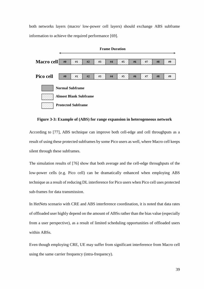
39
both networks layers (macro/ low-power cell layers) should exchange ABS subframe
information to achieve the required performance [69].
#0 #1 #2 #3 #4 #5 #6 #7Macro cell
Pico cell
Normal Subframe
Almost Blank Subframe
#8 #9
#0 #1 #2 #3 #4 #5 #6 #7 #8 #9
Protected Subframe
Frame Duration
Figure 3-3: Example of (ABS) for range expansion in heterogeneous network
According to [77], ABS technique can improve both cell-edge and cell throughputs as a
result of using these protected subframes by some Pico users as well, where Macro cell keeps
silent through these subframes.
The simulation results of [76] show that both average and the cell-edge throughputs of the
low-power cells (e.g. Pico cell) can be dramatically enhanced when employing ABS
technique as a result of reducing DL interference for Pico users when Pico cell uses protected
sub-frames for data transmission.
In HetNets scenario with CRE and ABS interference coordination, it is noted that data rates
of offloaded user highly depend on the amount of ABSs rather than the bias value (especially
from a user perspective), as a result of limited scheduling opportunities of offloaded users
within ABSs.
Even though employing CRE, UE may suffer from significant interference from Macro cell
using the same carrier frequency (intra-frequency).
40
3.4 Related Work in ICIC
3GPP has suggested TD-ICIC as a time-domain multiplexing technique for cross-tier
interference mitigation in LTE Release 10 HetNets [54], which is called Almost Blank
Subframes (ABS). In this technique, the aggressive node should refrain from transmitting
data on a certain amount of spectrum (subframes or resource blocks) to be protected for the
cell-edge users of the victim node that shares the same frequency band(s). In this way, only
cell-specific reference signals (CRSs) [78], [79] and other synchronisation and paging
signals will be transmitted through these subframes to keep the backwards compatibility with
older versions of LTE UEs. Moreover, CRSs are used for radio resources management and
channel estimation, so they are necessary to still being transmitted during these subframes.
A scheduler has been proposed in [80] which effectively coordinates the inter-cell
interference for vulnerable users of LTE-A HetNets with a minimum efforts of coordination
using dynamic FFR. In this work, a decentralised resource allocation algorithm is embedded
in the framework of LTE to avoid the interference on the cell edge users while maximising
the sum throughput of the cell. The proposed scheduler exploits X2 interface to inform the
neighbour cells with the reserved resources for its vulnerable users. Therefore, the results
show substantial gain as compared to the standard schedulers.
The author of [81] proposes an ABS setting for DL interference management based on base
station placement statistics, where UE can estimate the distance from BS by performing
RSRP measurement. The results of simulation show a moderate performance gain for victim
users in Macro/ Femto scenario, while it is substantial in Macro/ Pico scenario. They also
show that in Macro/ Pico scenario using ABS with association bias improves the
performance of the system considerably, so the fraction of victim users in outage decreases
from over 95% to 30% or less, depending on the scheduling algorithm.
41
A large CRE for a given Pico cell requires larger ABS duty cycle (ratio of ABS to non-ABS
subframes) to provide the desired QoS to PUEs in expanded region with the price of
degraded MUE performance. Macro cell ABS duty cycle calculation with a load balance
algorithm is proposed in [82] to offer a largest possible number of ABS to Pico cells while
controlling MUE performance to achieve better spatial reuse. The load balance algorithm
can be summarised when each Pico cell estimates the worst PUEs on their associated SINR
on both ABS and non-ABS subframes. Based on achievable rate got from SINR, Pico cell
decides to schedule those users with worst SINR on the suitable subframe. A dynamic cell
selection framework is suggested in [83] for eICIC with two cell association algorithms: one
for pure load balance and opportunistic approach for varying cell conditions. Besides this
algorithm, an autonomous fast distributed muting algorithm suitable for irregular network
deployment is developed for efficient eICIC. These two algorithms show higher capacity
gains depending on the deployment environment.
Dynamic configuration of ABS ratio has got a significant interest to adapt the variation in
network load. The effect of dynamic ABS according to a certain criterion is studied in [84],
[85], [86].
A framework was proposed by [87] for network dependant eICIC taking into account the
ABS ratio, UE association, and the CRE value jointly for optimal dynamic eICIC
configuration. This framework uses two algorithms: first algorithm is developed to find the
optimal ABS percentage and biasing value with static UEs scenario. After that, the second
algorithm specifies the appropriate ABS pattern for these protected subframes. This
framework was evaluated using Monte Carlo-based techniques to estimate the UE locations
according to UEs densities and SINR distributions. The only drawback of this proposal is

42
the high computation complexity during the joint computation, which could not adapt the
prompt channel estimation in the network. As a result of this computation complexity, it
takes 5-15 minutes to update the eICIC parameters, which increases the configuration outage
especially in the case of significant load changes over the network.
Moreover, [88] proposes a dynamic ABS scheme based on Genetic algorithm for the
optimum ABS ratio and location to mitigate the inter-cell interference efficiently for video
streaming traffic in Macro/ Pico deployment with shared bandwidth. This scheme proves an
improved user throughput and less outage probability when the ABS percentage has been
suggested to be 10%, 50%, and 70% for 9, 12, and 15 dB bising, respectively. The simulation
results show lower Macro throughput in low biasing values (e.g. 9dB) as a result of higher
users connected to the Macro cell. Moreover, the ABS ratio has been proved to be set jointly
with the biasing value to provide sufficient resources for all users in the network. However,
this scheme has been applied for video streaming only and the ABS configuration was not
fully dynamic. The conclusion shows that such configuration outperforms the static
allocation only in higher CSO (for the full-buffer case) thanks to the higher load in CE
region, while the static configuration is sufficient in lower CSO values since there are no
many users in CE region in the latter case.
As mentioned earlier that cell association in LTE is essentially based on RSRP, so it is a
critical issue to choose the appropriate CRE values in heterogeneous deployment to maintain
a sufficient SINR for the users in that region.
CRE bias should be carefully selected to ensure the maximum benefits of such solution;
small bias leads to fewer users to be offloaded towards the small cell [89], whereas the large
bias can cause weak SINR for some users inside CE region which affects the CCHs decoding
[90]. Several studies give an interest to the range of CSO values in HetNets; It was founded
43
in [91] that optimal CSO value is closer to 6 dB than 12 dB. A cell selection scheme (based
on Average SINR with different CSO values) and variable ABS densities are investigated in
[36] to improve the spectrum efficiency-in time domain- and overall performance of both
Macro/ Pico cells. However, the optimisation of CRE bias is seldom investigated by most
researchers [92].
From the literature, it can be concluded that dynamic configuration for CRE bias value based
on user distribution can optimally adapt user distribution within LTE-A HetNet to achieve
better cell-splitting gain with the price of computation and mobility complexity. It is
proposed in [93] a method for Pico-specific upper bound CRE bias estimation algorithm, to
ensure the SINR requirements for Pico-UEs. It focuses on the method of CRE bias setting
for Pico cell according to the power of ABS in HetNet.
TD-ICIC with CRE is a vital factor in cell planning. However, most works in [94]–[96] about
cell planning was not considering it. The parameter values for CRE and TD-ICIC depends
on the volume and distribution of data traffic. The author of [97] suggests a cell planning
model for the downlink in HetNet with CRE and TD-ICIC, to find the minimum number of
Pico cells under the constraint of covering all user data traffic. This planning is conducted
for traffic distributions by a greedy algorithm, taking into account CRE values with ABS
ratios and transmit power as well. It is concluded from the simulation results that ABS ratio
and resources needed for LPCs is proportional with CRE region.
Almost Blank Subframe can effectively enhance the performance of the cell-edge users of
the victim node with the cost of aggressor node’s performance degradation since the
aggressive node will not use these subframes.
RPS or Low-power Subframes (LP-ABS) is the most recent scheme proposed by 3GPP for
Further enhanced ICIC (FeICIC) in LTE Release 11, to avoid such degradation [98], [99].
44
Instead of totally blanking some subframes, LP-ABS can be used by the aggressive node
with reduced transmit power for better resources efficiency, giving priority to cell-centre
UEs of the aggressor node to be scheduled on these subframes [99]. The transmit power of
LP-ABS should be decreased (at least) as much as the CRE bias (or HO offset) compared to
one of the normal subframes [100] or even adopt much lower power, such as 30 dBm as
mentioned in [101] to guarantee the Macro cell edge user performance. Obviously, the
optimum power level is variable which is dependent on the ABS ratio, CRE value and
channel model, and so forth. For simplification, the 30dBm transmission power is always
assumed for reduced-power ABS regardless of actual CRE bias value even if this is not the
optimum value.
However, for the stable network operation purpose, the PCFICH, PDCCH and PDSCH,
which are employed to transfer system information, are not suitable to transmit with low
power. The purpose is to ensure the coverage of all the served UE[102].
A detailed analysis of RPS performance is given in [103]; based on their simulation results,
RPS could provide relatively more steady performance gain in the cell average and cell edge
throughput compared to ABS configuration. RPS configuration could boost both cell
average and cell edge throughputs. A new user association method under RPS scheme has
been proposed in [104] to investigate the network performance using stochastic geometry
framework. Furthermore, the formula for an optimal biasing value has been analytically
derived to maximise the overall rate coverage of the network. The analytical results show
the RPS scheme proves better performance in static range expansion biasing provided that
optimum resource sharing is achieved.
Further research studies focus on the optimum power consumption as an important factor in
mobile networks. [105] proposed a centralised algorithm for joint user association and power
45
minimisation in DL transmission of two-tier LTE-A network. This algorithm is derived using
Lagrange dual composition method to study the load coupling and the protected subframe
ratio impact on the SINR of the network. Likewise, [106] studies the optimisation of FeICIC
and analyses the Energy Efficiency (EE) and SE in a two-tier LTE-A network using
stochastic geometry. The simulation results under the stochastic geometry show a slight
improvement (0.55 bit/s/Hz/W) with a CRE biasing of 12 dB as a best result. However, there
was a trade-off between SE and EE in higher Pico cell density. In addition, [107] designs a
power saving framework to modify the ABS pattern dynamically in a short term (i.e. few
milliseconds), and to keep the traffic estimation at reduced power cost with less latency. It
shows less power consumptions as compared to other employed frameworks, especially at
low loads. On the other hand, the network service is degraded proportionally for all cells in
the case of over loading. This degradation is a result of varying the transmit power of the
RPS dynamically which leads to unnecessary interference fluctuation.
More advanced research on the impact of the small cell interference to the Macro cell has
been tackled in [108], where an RPS scheme is introduced for both Macro and Femto cells
to mitigate the interference on the Macro-edge users, in addition to protecting the Femto
users from the high transmit power of the Macro cell. The analytical framework was derived
and verified using Monte Carlo simulation, where the SINR of both edge and average user’s
throughputs are enhanced under the proposed framework. Therefore, the numerical results
show up to 20% enhancements in Macro edge coverage gain when employing RPS in Femto
cell.
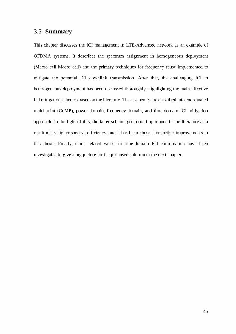
46
3.5 Summary
This chapter discusses the ICI management in LTE-Advanced network as an example of
OFDMA systems. It describes the spectrum assignment in homogeneous deployment
(Macro cell-Macro cell) and the primary techniques for frequency reuse implemented to
mitigate the potential ICI downlink transmission. After that, the challenging ICI in
heterogeneous deployment has been discussed thoroughly, highlighting the main effective
ICI mitigation schemes based on the literature. These schemes are classified into coordinated
multi-point (CoMP), power-domain, frequency-domain, and time-domain ICI mitigation
approach. In the light of this, the latter scheme got more importance in the literature as a
result of its higher spectral efficiency, and it has been chosen for further improvements in
this thesis. Finally, some related works in time-domain ICI coordination have been
investigated to give a big picture for the proposed solution in the next chapter.
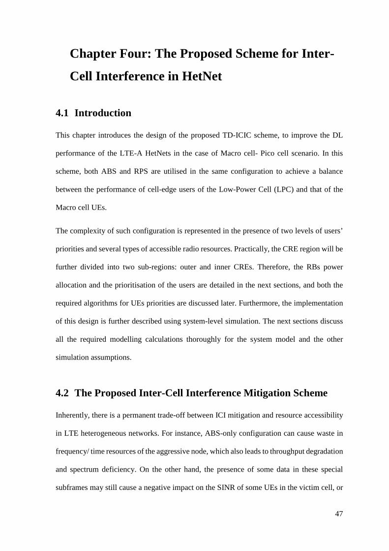
47
4 Chapter Four: The Proposed Scheme for Inter-
Cell Interference in HetNet
4.1 Introduction
This chapter introduces the design of the proposed TD-ICIC scheme, to improve the DL
performance of the LTE-A HetNets in the case of Macro cell- Pico cell scenario. In this
scheme, both ABS and RPS are utilised in the same configuration to achieve a balance
between the performance of cell-edge users of the Low-Power Cell (LPC) and that of the
Macro cell UEs.
The complexity of such configuration is represented in the presence of two levels of users’
priorities and several types of accessible radio resources. Practically, the CRE region will be
further divided into two sub-regions: outer and inner CREs. Therefore, the RBs power
allocation and the prioritisation of the users are detailed in the next sections, and both the
required algorithms for UEs priorities are discussed later. Furthermore, the implementation
of this design is further described using system-level simulation. The next sections discuss
all the required modelling calculations thoroughly for the system model and the other
simulation assumptions.
4.2 The Proposed Inter-Cell Interference Mitigation Scheme
Inherently, there is a permanent trade-off between ICI mitigation and resource accessibility
in LTE heterogeneous networks. For instance, ABS-only configuration can cause waste in
frequency/ time resources of the aggressive node, which also leads to throughput degradation
and spectrum deficiency. On the other hand, the presence of some data in these special
subframes may still cause a negative impact on the SINR of some UEs in the victim cell, or
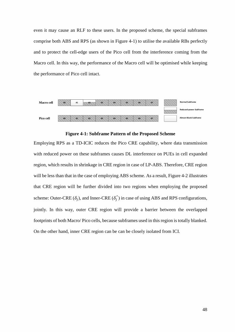
48
even it may cause an RLF to these users. In the proposed scheme, the special subframes
comprise both ABS and RPS (as shown in Figure 4-1) to utilise the available RBs perfectly
and to protect the cell-edge users of the Pico cell from the interference coming from the
Macro cell. In this way, the performance of the Macro cell will be optimised while keeping
the performance of Pico cell intact.
#0 #1 #2 #3 #4 #5 #6 #7
#0 #1 #2 #3 #4 #5 #6 #7
Macro cell
Pico cell
#1 #2#1
Reduced-power Subframe
Normal Subframe
Almost Blank Subframe
Figure 4-1: Subframe Pattern of the Proposed Scheme
Employing RPS as a TD-ICIC reduces the Pico CRE capability, where data transmission
with reduced power on these subframes causes DL interference on PUEs in cell expanded
region, which results in shrinkage in CRE region in case of LP-ABS. Therefore, CRE region
will be less than that in the case of employing ABS scheme. As a result, Figure 4-2 illustrates
that CRE region will be further divided into two regions when employing the proposed
scheme: Outer-CRE (𝛿𝛿𝑗𝑗), and Inner-CRE (𝛿𝛿𝑗𝑗^) in case of using ABS and RPS configurations,
jointly. In this way, outer CRE region will provide a barrier between the overlapped
footprints of both Macro/ Pico cells, because subframes used in this region is totally blanked.
On the other hand, inner CRE region can be can be closely isolated from ICI.
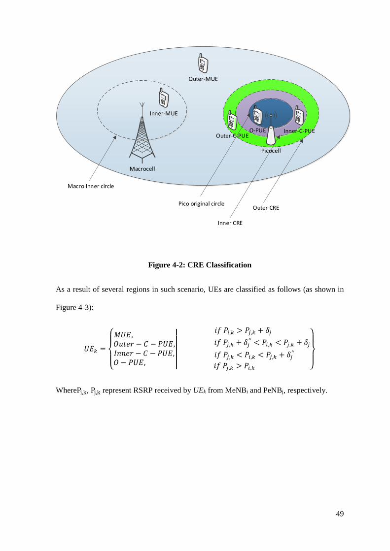
49
Outer-MUE
Macrocell
Picocell
Inner-MUE
Outer-C-PUEInner-C-PUEO-PUE
Macro Inner circle
Pico original circle
Inner CRE
Outer CRE
Figure 4-2: CRE Classification
As a result of several regions in such scenario, UEs are classified as follows (as shown in
Figure 4-3):
𝑈𝑈𝑈𝑈𝑘𝑘 =
⎩⎪⎨
⎪⎧𝑀𝑀𝑈𝑈𝑈𝑈, 𝑂𝑂𝑂𝑂𝑂𝑂𝑂𝑂𝑂𝑂 − 𝐶𝐶 − 𝑃𝑃𝑈𝑈𝑈𝑈,𝐼𝐼𝐼𝐼𝐼𝐼𝑂𝑂𝑂𝑂 − 𝐶𝐶 − 𝑃𝑃𝑈𝑈𝑈𝑈,𝑂𝑂 − 𝑃𝑃𝑈𝑈𝑈𝑈,
��
𝑖𝑖𝑖𝑖 𝑃𝑃𝑖𝑖,𝑘𝑘 > 𝑃𝑃𝑗𝑗,𝑘𝑘 + 𝛿𝛿𝑗𝑗 𝑖𝑖𝑖𝑖 𝑃𝑃𝑗𝑗,𝑘𝑘 + 𝛿𝛿𝑗𝑗^ < 𝑃𝑃𝑖𝑖,𝑘𝑘 < 𝑃𝑃𝑗𝑗,𝑘𝑘 + 𝛿𝛿𝑗𝑗
𝑖𝑖𝑖𝑖 𝑃𝑃𝑗𝑗,𝑘𝑘 < 𝑃𝑃𝑖𝑖,𝑘𝑘 < 𝑃𝑃𝑗𝑗,𝑘𝑘 + 𝛿𝛿𝑗𝑗^
𝑖𝑖𝑖𝑖 𝑃𝑃𝑗𝑗,𝑘𝑘 > 𝑃𝑃𝑖𝑖,𝑘𝑘 ⎭⎪⎬
⎪⎫
WherePi,k, Pj,k represent RSRP received by UEk from MeNBi and PeNBj, respectively.

50
Figure 4-3: Users Classification
For all described notations, refer to Table 4-2.
4.2.1 Physical Resource Blocks Power Allocation
Conventionally, the total transmit power is distributed uniformly among the available
physical resource blocks in every transmission period. In addition, only homogeneous power
allocation is supported in the recent version of Vienna simulator [109]. However, there is a
variable power allocation used in my proposed scheme which needs to modify the power
allocation in the simulation tool. Therefore, RB power allocation was modified by accessing
the resource block grid file in the simulator to change the power per RB based on the
proposed scheme. After the normal power allocation in PRBs, ABS RBs got zero transmit
power, while the RPS got half the share of the normal RBs. The reason behind choosing half
the share of the transmit power for the RPSs is to maintain an optimum user and cell
throughputs of the network. There is a trade of between Pico/ Macro cells performance for
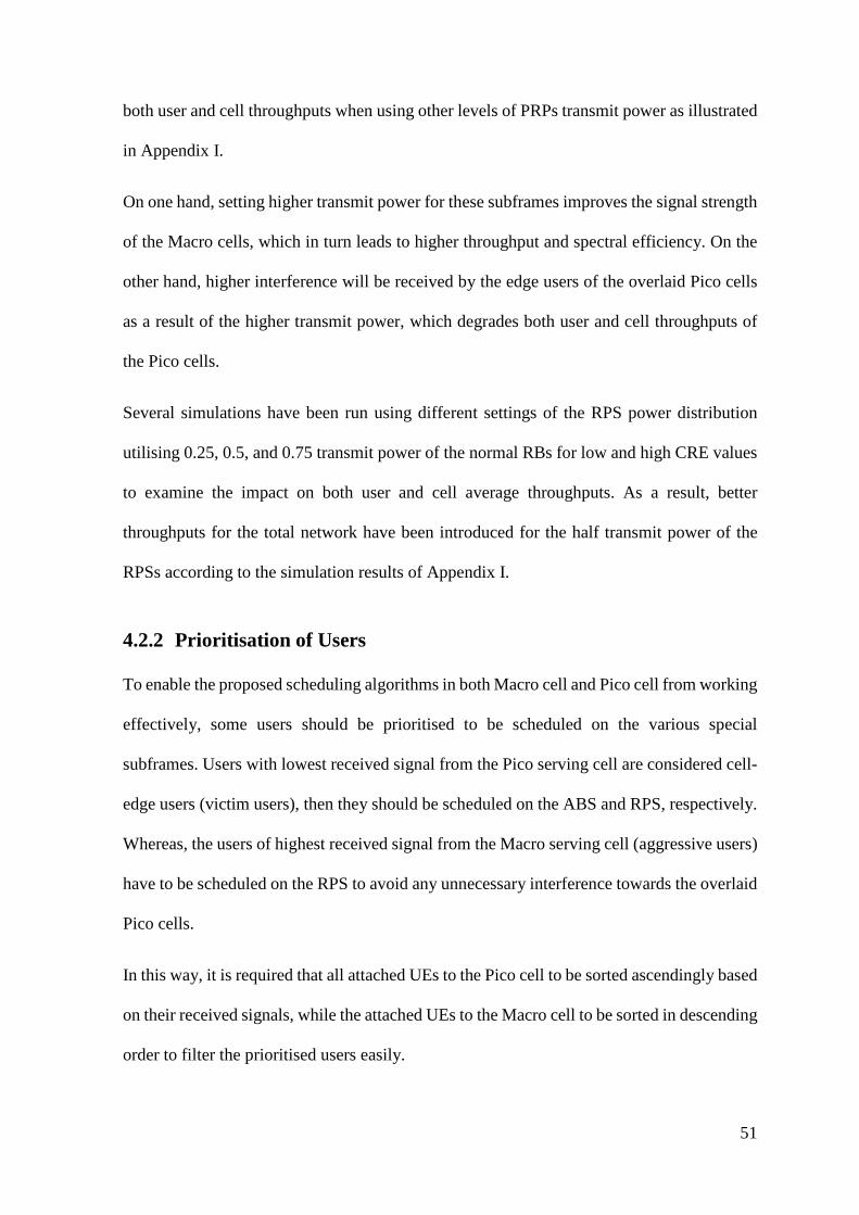
51
both user and cell throughputs when using other levels of PRPs transmit power as illustrated
in Appendix I.
On one hand, setting higher transmit power for these subframes improves the signal strength
of the Macro cells, which in turn leads to higher throughput and spectral efficiency. On the
other hand, higher interference will be received by the edge users of the overlaid Pico cells
as a result of the higher transmit power, which degrades both user and cell throughputs of
the Pico cells.
Several simulations have been run using different settings of the RPS power distribution
utilising 0.25, 0.5, and 0.75 transmit power of the normal RBs for low and high CRE values
to examine the impact on both user and cell average throughputs. As a result, better
throughputs for the total network have been introduced for the half transmit power of the
RPSs according to the simulation results of Appendix I.
4.2.2 Prioritisation of Users
To enable the proposed scheduling algorithms in both Macro cell and Pico cell from working
effectively, some users should be prioritised to be scheduled on the various special
subframes. Users with lowest received signal from the Pico serving cell are considered cell-
edge users (victim users), then they should be scheduled on the ABS and RPS, respectively.
Whereas, the users of highest received signal from the Macro serving cell (aggressive users)
have to be scheduled on the RPS to avoid any unnecessary interference towards the overlaid
Pico cells.
In this way, it is required that all attached UEs to the Pico cell to be sorted ascendingly based
on their received signals, while the attached UEs to the Macro cell to be sorted in descending
order to filter the prioritised users easily.
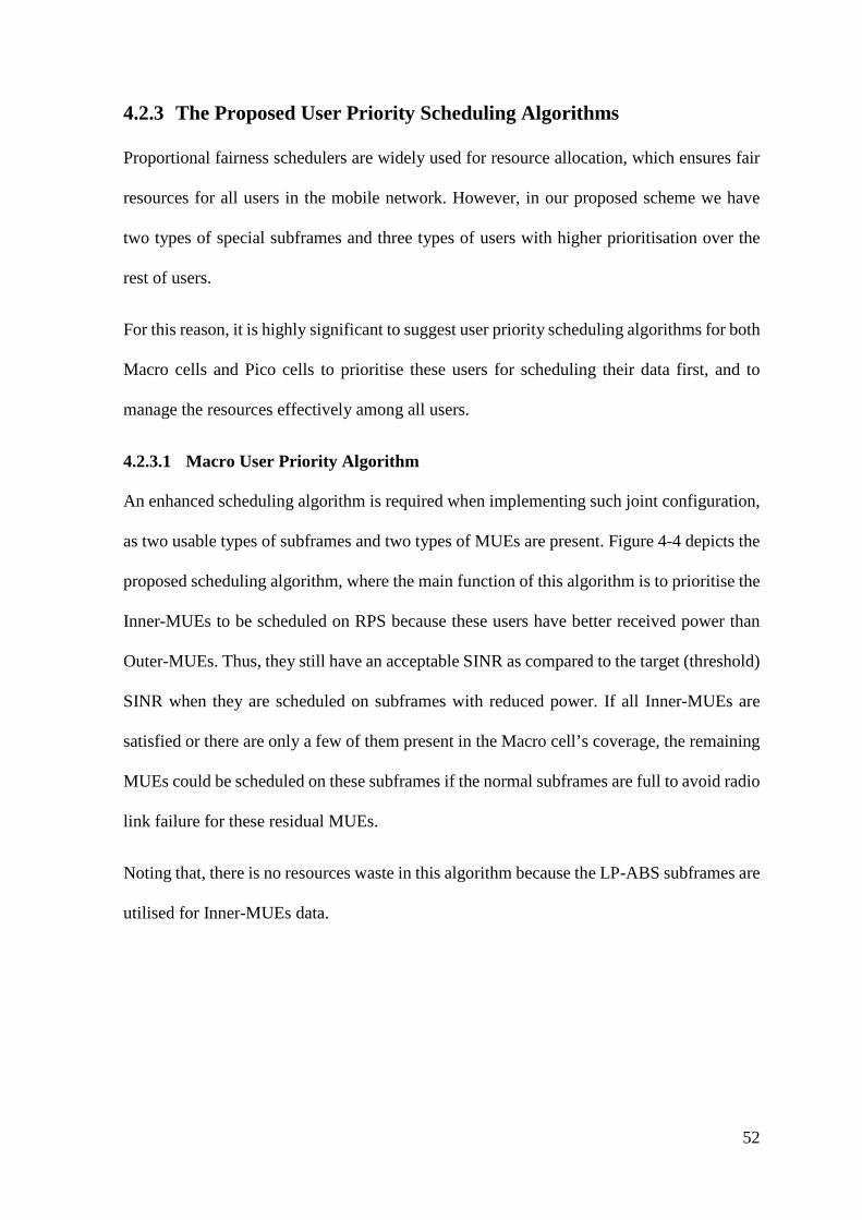
52
4.2.3 The Proposed User Priority Scheduling Algorithms
Proportional fairness schedulers are widely used for resource allocation, which ensures fair
resources for all users in the mobile network. However, in our proposed scheme we have
two types of special subframes and three types of users with higher prioritisation over the
rest of users.
For this reason, it is highly significant to suggest user priority scheduling algorithms for both
Macro cells and Pico cells to prioritise these users for scheduling their data first, and to
manage the resources effectively among all users.
4.2.3.1 Macro User Priority Algorithm
An enhanced scheduling algorithm is required when implementing such joint configuration,
as two usable types of subframes and two types of MUEs are present. Figure 4-4 depicts the
proposed scheduling algorithm, where the main function of this algorithm is to prioritise the
Inner-MUEs to be scheduled on RPS because these users have better received power than
Outer-MUEs. Thus, they still have an acceptable SINR as compared to the target (threshold)
SINR when they are scheduled on subframes with reduced power. If all Inner-MUEs are
satisfied or there are only a few of them present in the Macro cell’s coverage, the remaining
MUEs could be scheduled on these subframes if the normal subframes are full to avoid radio
link failure for these residual MUEs.
Noting that, there is no resources waste in this algorithm because the LP-ABS subframes are
utilised for Inner-MUEs data.
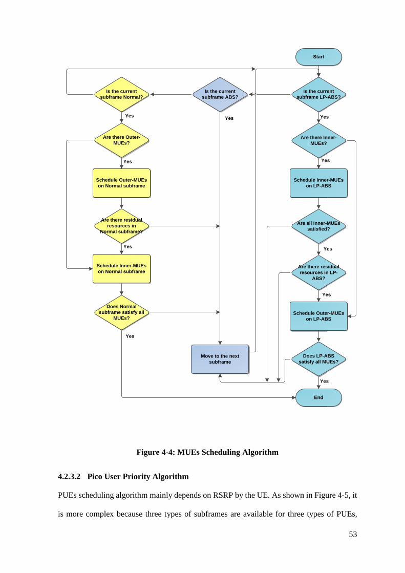
53
Start
Is the current subframe LP-ABS?
Schedule Inner-MUEs on LP-ABS
Are there Inner-MUEs?
Are there residual resources in LP-
ABS?
Schedule Outer-MUEs on LP-ABS
Does LP-ABS satisfy all MUEs?
End
Yes
Yes
Yes
Yes
Is the current subframe Normal?
Are there Outer-MUEs?
Schedule Outer-MUEs on Normal subframe
Are there residual resources in
Normal subframe?
Schedule Inner-MUEs on Normal subframe
Does Normal subframe satisfy all
MUEs?
Move to the next subframe
Is the current subframe ABS?
Are all Inner-MUEs satisfied?
Yes
YesYes
Yes
Yes
Yes
Figure 4-4: MUEs Scheduling Algorithm
4.2.3.2 Pico User Priority Algorithm
PUEs scheduling algorithm mainly depends on RSRP by the UE. As shown in Figure 4-5, it
is more complex because three types of subframes are available for three types of PUEs,
54
giving highest priority in scheduling to the Outer-C-UEs on ABS then the second highest
priority to the Inner-C-UEs on RPS. Finally, the rest of Pico UEs will be scheduled as normal
by the proportional fairness scheduler.
Yes
Yes
Yes
Yes
Yes
Yes
Yes
Yes
Yes
Yes
Yes
Yes
Start
Is the current subframe ABS?
Schedule Outer-C-PUEs on ABS
Are there Outer-C-PUEs?
Are there residual resources in ABS?
Schedule Inner-C-PUEs on ABS
Does ABS satisfy all C-PUEs?
End
Is the current subframe LP-ABS?
Schedule Inner-C-PUEs on LP-ABS subframe
Are Inner-C-PUEs satisfied?
Move to the next subframe
Is the current subframe Normal?
Are all Outer-C-PUEs satisfied?
Does ABS satisfy all PUEs?
Schedule the rest of PUEs on ABS
Schedule the rest of PUEs on LP-ABS
Does LP-ABS satisfy all PUEs?
Schedule the rest of PUEs on Normal
subframe
Are all PUEs satisfied?
Are there Inner-C-PUEs?
Figure 4-5: PUEs Scheduling Algorithm
55
4.3 System-Level Simulation of LTE-Advanced Networks
This research was conducted to design a joint scheme for inter-cell interference mitigation
in LTE-A heterogeneous networks as an example of Orthogonal Frequency Division
Multiple Access (OFDMA). It is also significant to analyse and evaluate the advantage of
this proposed scheme over the already employed interference mitigation schemes as a part
of research aim and objectives.
System-level simulations are required to create a model of a complex mobile network and
to investigate the system performance under certain parameters and assumptions. To achieve
this target, Vienna Simulator [110] has been used and modified as a downlink system level
simulator to model an LTE-A mobile network with the proposed project. It has been chosen
to implement the proposed scheme because it supports the physical layer of the LTE system.
Moreover, it is an MATLAB-based LTE-A system-level simulator (supports both uplink and
downlink systems), released by University of Vienna under the terms of academic, non-
commercial use license. Therefore, there is a great support from the developers of this
simulator through an online forum for all raised issues in any stage of the simulation.
4.3.1 Simulation Assumptions
This section introduces some simulation assumptions that have been adopted to model the
LTE-A Heterogeneous network, consists of Macro cells and overlaid by several Pico cells
as small cells:
• Most studies only take into account one interfering Macro cell to LPCs in HetNets,
while few researches [90], [111] include the interference coming from adjacent
Macro cells in LTE-Advanced HetNets, which should be involved in this scenario.
• The subframe pattern used in our scenario is depicted in Figure 4-1; where one
subframe is totally blanked to for Outer CRE, while another subframe is reserved for
56
Inner-CRE with a reduced transmit power. Noting that, this pattern is repeated with
duration of 8 milliseconds to support HARQ function in case of any radio link failure
[112].
• With a bitmap of 40 bit, all possible special subframes configurations aligning with
8 ms uplink HARQ timing can be addressed in FDD deployments of heterogeneous
networks [112].
• Assuming that all subcarriers within an RB of normal subframes experience the same
radio channel conditions at any given time (i.e. frequency flat-fading in an RB) [113].
• The radio link is subject to propagation loss and log-normally distributed shadowing,
while the fast fading is negligible for ease of simulation.
• In the simulations, perfect channel estimation, and perfect synchronisation are
assumed. Channel estimation is assumed perfect, and 3GPP extended spatial channel
model (SCME) is considered [84].
• Feedback channel delay is 1 Transmission Time Interval (1 TTI), which is the
minimum delay for ACK reports [110].
• We assumed two mobility profiles: mobile users with a low speed of 5 km/h and only
local mobility, such that no handovers occur [84], and higher vehicular speed of 60
km/h (with handover functionality) to investigate the impact of the high mobility on
the proposed scheme. Both mobility profiles imply random routes for the mobile
users.
• AWGN noise power is calculated by multiplying the noise power spectral density N0
by the bandwidth of a unit resource block B/N.
• There are no latency constraints associated with simulated traffic.
• Total simulation time is 40 milliseconds (40 TTIs), and the map resolution is 5 m/
pixels.
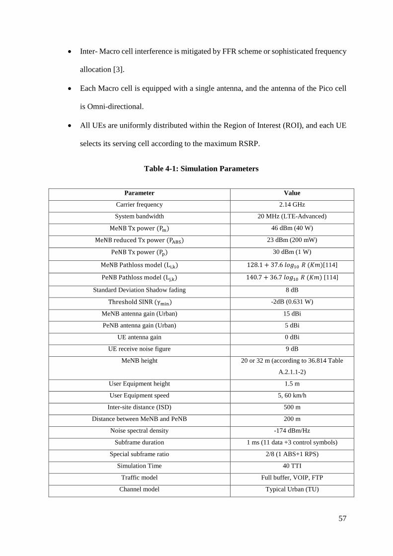
57
• Inter- Macro cell interference is mitigated by FFR scheme or sophisticated frequency
allocation [3].
• Each Macro cell is equipped with a single antenna, and the antenna of the Pico cell
is Omni-directional.
• All UEs are uniformly distributed within the Region of Interest (ROI), and each UE
selects its serving cell according to the maximum RSRP.
Table 4-1: Simulation Parameters
Parameter Value
Carrier frequency 2.14 GHz
System bandwidth 20 MHz (LTE-Advanced)
MeNB Tx power (Pm) 46 dBm (40 W)
MeNB reduced Tx power (PABS) 23 dBm (200 mW)
PeNB Tx power (Pp) 30 dBm (1 W)
MeNB Pathloss model (Li,k) 128.1 + 37.6 𝑙𝑙𝑙𝑙𝑙𝑙10 𝑅𝑅 (𝐾𝐾𝐾𝐾)[114]
PeNB Pathloss model (Lj,k) 140.7 + 36.7 𝑙𝑙𝑙𝑙𝑙𝑙10 𝑅𝑅 (𝐾𝐾𝐾𝐾) [114]
Standard Deviation Shadow fading 8 dB
Threshold SINR (γmin) -2dB (0.631 W)
MeNB antenna gain (Urban) 15 dBi
PeNB antenna gain (Urban) 5 dBi
UE antenna gain 0 dBi
UE receive noise figure 9 dB
MeNB height 20 or 32 m (according to 36.814 Table
A.2.1.1-2)
User Equipment height 1.5 m
User Equipment speed 5, 60 km/h
Inter-site distance (ISD) 500 m
Distance between MeNB and PeNB 200 m
Noise spectral density -174 dBm/Hz
Subframe duration 1 ms (11 data +3 control symbols)
Special subframe ratio 2/8 (1 ABS+1 RPS)
Simulation Time 40 TTI
Traffic model Full buffer, VOIP, FTP
Channel model Typical Urban (TU)
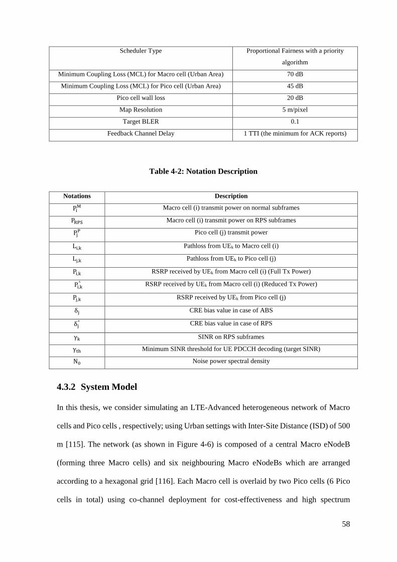
58
Scheduler Type Proportional Fairness with a priority
algorithm
Minimum Coupling Loss (MCL) for Macro cell (Urban Area) 70 dB
Minimum Coupling Loss (MCL) for Pico cell (Urban Area) 45 dB
Pico cell wall loss 20 dB
Map Resolution 5 m/pixel
Target BLER 0.1
Feedback Channel Delay 1 TTI (the minimum for ACK reports)
Table 4-2: Notation Description
Notations Description
PiM Macro cell (i) transmit power on normal subframes
PRPS Macro cell (i) transmit power on RPS subframes
PjP Pico cell (j) transmit power
Li,k Pathloss from UEk to Macro cell (i)
Lj,k Pathloss from UEk to Pico cell (j)
Pi,k RSRP received by UEk from Macro cell (i) (Full Tx Power)
Pi,k^ RSRP received by UEk from Macro cell (i) (Reduced Tx Power)
Pj,k RSRP received by UEk from Pico cell (j)
δj CRE bias value in case of ABS
δj^ CRE bias value in case of RPS
γk SINR on RPS subframes
γth Minimum SINR threshold for UE PDCCH decoding (target SINR)
N0 Noise power spectral density
4.3.2 System Model
In this thesis, we consider simulating an LTE-Advanced heterogeneous network of Macro
cells and Pico cells , respectively; using Urban settings with Inter-Site Distance (ISD) of 500
m [115]. The network (as shown in Figure 4-6) is composed of a central Macro eNodeB
(forming three Macro cells) and six neighbouring Macro eNodeBs which are arranged
according to a hexagonal grid [116]. Each Macro cell is overlaid by two Pico cells (6 Pico
cells in total) using co-channel deployment for cost-effectiveness and high spectrum
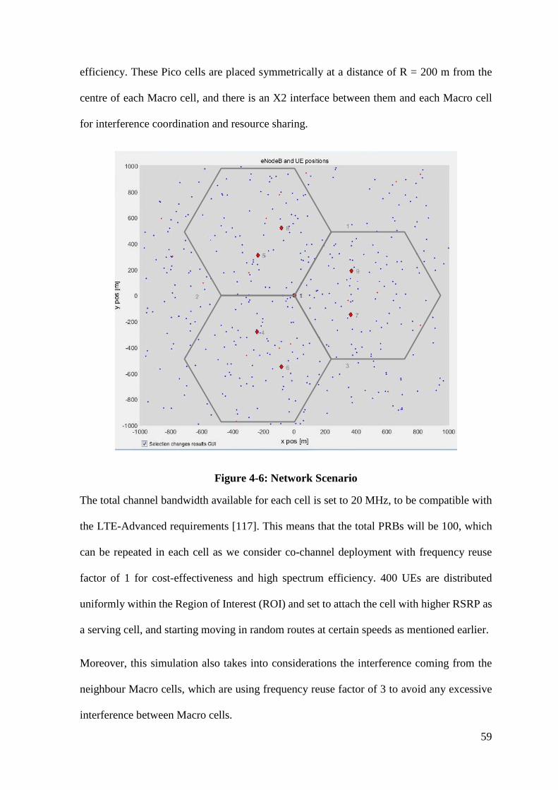
59
efficiency. These Pico cells are placed symmetrically at a distance of R = 200 m from the
centre of each Macro cell, and there is an X2 interface between them and each Macro cell
for interference coordination and resource sharing.
Figure 4-6: Network Scenario
The total channel bandwidth available for each cell is set to 20 MHz, to be compatible with
the LTE-Advanced requirements [117]. This means that the total PRBs will be 100, which
can be repeated in each cell as we consider co-channel deployment with frequency reuse
factor of 1 for cost-effectiveness and high spectrum efficiency. 400 UEs are distributed
uniformly within the Region of Interest (ROI) and set to attach the cell with higher RSRP as
a serving cell, and starting moving in random routes at certain speeds as mentioned earlier.
Moreover, this simulation also takes into considerations the interference coming from the
neighbour Macro cells, which are using frequency reuse factor of 3 to avoid any excessive
interference between Macro cells.
60
In addition, CRE of 3 dB step is also be used to observe the impact of offloaded users towards
the Pico cells. Noting that, propagation, traffic, and other models will be further detailed in
section 4.3.
• Network Definition
To define an LTE-Advanced heterogeneous network, we need to introduce some general
notations as follows:
• Macro cells: M = {M1, ..., Mm, Mn, ..., MM},
• Where Nm ={𝑁𝑁1 𝑚𝑚 , … ,𝑁𝑁𝑏𝑏𝑚𝑚, … ,𝑁𝑁𝑁𝑁𝑚𝑚
𝑚𝑚 } is the set of neighbouring cells of Macro cell
Mm,
• Pico cells: P = {P1, ..., Pf, Pg, ..., Pp },
• Where Np={𝑁𝑁1𝑝𝑝, … ,𝑁𝑁𝑏𝑏
𝑝𝑝 , … ,𝑁𝑁𝑁𝑁𝑝𝑝𝑝𝑝 } is the set of neighbouring cell of Pico cell Pp,
• Macro users: Mm: Um= {𝑈𝑈1𝑚𝑚, … ,𝑈𝑈𝑢𝑢𝑚𝑚, … ,𝑈𝑈𝑈𝑈𝑚𝑚𝑚𝑚 },
• Pico users: Pp: Up={𝑈𝑈1𝑝𝑝, … ,𝑈𝑈𝑢𝑢
𝑝𝑝, … ,𝑈𝑈𝑈𝑈𝑝𝑝𝑝𝑝 },
• Subframes: S={1, …, s, …, S},
• Resource Blocks (RBs): R={1, …, r, …, R},
4.3.3 Traffic Model
Full-buffer traffic is considered in this thesis, which may represent the worst case among the
other types of traffic models. In the full-buffer model, the number of users in the network is
fixed, and each user’s session lasts forever to create infinite data volume. In this way, the
radio links are always utilised, and all cells are fully-loaded all the times. However, users
with different radio conditions spend the same time in the system, in turn, leads to less
61
generated data for users with poor radio conditions. “As a conclusion, full-buffer gives
optimistic performance estimation which may deviate from reality” [118].
Noting that other types of traffic (FTP and VOIP) have been simulated for the proposed
scheme and the simulation results are shown in Appendix II
4.3.4 Propagation Model
Mainly, heterogeneous networks are deployed in urban environments to cover the highly
dense areas. Therefore, the urban model will be the most suitable model used in our
simulations to evaluate the propagation path loss due to distance. In such types of models,
radio wave propagation has two dominant paths which are over the rooftop and along the
street. The first path is more dominant when the user is far from the cell, while the second
path is more considerable as long as the user is close to the cell [118].
The received power in both downlink and uplink can be expressed as [114]:
G_RX,MCL)G_TXssMax(pathloTX_PWRRX_PWR −−−= (4-1)
Where:
RX_PWR is the received signal power
TX_PWR is the transmitted signal power
G_TX is the transmitter antenna gain
G_RX is the receiver antenna gain
The propagation model for the Macro cell in urban environments can be express as [114]:
dB(f)(Dhb)(R)Dhb)(L 80log21log18log104140 1010103 +⋅+⋅−⋅⋅⋅−⋅= − (4-2)
R is distance between Macro cell and user in kilometres
62
f is the frequency in MHz
Dhb is the Macro cell antenna height in meters, measured from rooftop level
When considering a carrier frequency of 2 GHz and a Macro cell antenna height of 15 m
above rooftop level, the propagation model will be in the following formula:
)(log6.371.128 10 RL += (4-3)
After L is calculated, log-normally distributed shadowing (Log F) with a standard deviation
of 8 dB should be added [119].
The path loss is given by the following formula:
LogFLacroPathloss_M += (4-4)
Noting that, this model describes worse case propagation and it is mainly designed for
distances ranging from few hundred meters to kilometres and not suitable for short distances.
Furthermore, the propagation model for the Pico cell in 2 GHz carrier frequency (for urban
environments) can be express as [115]:
)(log7.367.140 10 RL += (4-5)
4.3.5 Signal to Interference plus Noise Ratio (SINR) Model
The Signal-to Interference plus Noise Ratio (SINR) is a very important metric to be
considered in performance evaluation of any mobile networks. It is calculated by the user
and sent back to the network [5] to be mainly used for user throughput and cell capacity
calculations, taking into account the interference coming from the neighbouring cells/ users.
The general SINR equation for UEk attached to the cell (i) according to [120] is:
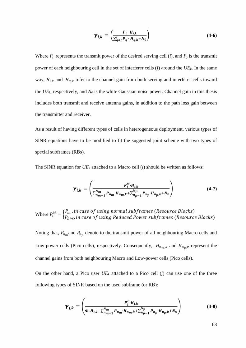
63
𝜸𝜸𝑺𝑺,𝒌𝒌 = � 𝑹𝑹𝑺𝑺 ∙ 𝑯𝑯𝑺𝑺,𝒌𝒌∑ 𝑹𝑹𝒒𝒒 ∙ 𝑯𝑯𝒒𝒒,𝒌𝒌+𝑵𝑵𝟎𝟎𝑰𝑰𝒒𝒒≠𝑺𝑺
� (4-6)
Where 𝑃𝑃𝑖𝑖 represents the transmit power of the desired serving cell (i), and 𝑃𝑃𝑞𝑞 is the transmit
power of each neighbouring cell in the set of interferer cells (I) around the UEk. In the same
way, 𝐻𝐻𝑖𝑖,𝑘𝑘 and 𝐻𝐻𝑞𝑞,𝑘𝑘 refer to the channel gain from both serving and interferer cells toward
the UEk, respectively, and N0 is the white Gaussian noise power. Channel gain in this thesis
includes both transmit and receive antenna gains, in addition to the path loss gain between
the transmitter and receiver.
As a result of having different types of cells in heterogeneous deployment, various types of
SINR equations have to be modified to fit the suggested joint scheme with two types of
special subframes (RBs).
The SINR equation for UEk attached to a Macro cell (i) should be written as follows:
𝜸𝜸𝑺𝑺,𝒌𝒌 = � 𝑹𝑹𝑺𝑺𝑴𝑴∙𝑯𝑯𝑺𝑺,𝒌𝒌
∑ 𝑹𝑹𝑺𝑺𝒎𝒎∙𝑯𝑯𝑺𝑺𝒎𝒎,𝒌𝒌+∑ 𝑹𝑹𝑺𝑺𝒑𝒑∙𝑯𝑯𝑺𝑺𝒑𝒑,𝒌𝒌+𝑵𝑵𝟎𝟎𝑵𝑵𝒑𝒑𝑺𝑺𝒑𝒑=𝟏𝟏
𝑵𝑵𝒎𝒎𝑺𝑺𝒎𝒎=𝟏𝟏
� (4-7)
Where 𝑃𝑃𝑖𝑖𝑀𝑀 = �𝑃𝑃𝑚𝑚 , 𝑖𝑖𝐼𝐼 𝑐𝑐𝑐𝑐𝑐𝑐𝑂𝑂 𝑙𝑙𝑖𝑖 𝑂𝑂𝑐𝑐𝑖𝑖𝐼𝐼𝑙𝑙 𝐼𝐼𝑙𝑙𝑂𝑂𝐾𝐾𝑐𝑐𝑙𝑙 𝑐𝑐𝑂𝑂𝑠𝑠𝑖𝑖𝑂𝑂𝑐𝑐𝐾𝐾𝑂𝑂𝑐𝑐 (𝑅𝑅𝑂𝑂𝑐𝑐𝑙𝑙𝑂𝑂𝑂𝑂𝑐𝑐𝑂𝑂 𝐵𝐵𝑙𝑙𝑙𝑙𝑐𝑐𝐵𝐵𝑐𝑐) 𝑃𝑃𝑅𝑅𝑅𝑅𝑅𝑅, 𝑖𝑖𝐼𝐼 𝑐𝑐𝑐𝑐𝑐𝑐𝑂𝑂 𝑙𝑙𝑖𝑖 𝑂𝑂𝑐𝑐𝑖𝑖𝐼𝐼𝑙𝑙 𝑅𝑅𝑂𝑂𝑅𝑅𝑂𝑂𝑐𝑐𝑂𝑂𝑅𝑅 𝑃𝑃𝑙𝑙𝑃𝑃𝑂𝑂𝑂𝑂 𝑐𝑐𝑂𝑂𝑠𝑠𝑖𝑖𝑂𝑂𝑐𝑐𝐾𝐾𝑂𝑂𝑐𝑐 (𝑅𝑅𝑂𝑂𝑐𝑐𝑙𝑙𝑂𝑂𝑂𝑂𝑐𝑐𝑂𝑂 𝐵𝐵𝑙𝑙𝑙𝑙𝑐𝑐𝐵𝐵𝑐𝑐)
Noting that, 𝑃𝑃𝑛𝑛𝑚𝑚and 𝑃𝑃𝑛𝑛𝑝𝑝 denote to the transmit power of all neighbouring Macro cells and
Low-power cells (Pico cells), respectively. Consequently, 𝐻𝐻𝑛𝑛𝑚𝑚,𝑘𝑘 and 𝐻𝐻𝑛𝑛𝑝𝑝,𝑘𝑘 represent the
channel gains from both neighbouring Macro and Low-power cells (Pico cells).
On the other hand, a Pico user UEk attached to a Pico cell (j) can use one of the three
following types of SINR based on the used subframe (or RB):
𝜸𝜸𝒋𝒋,𝒌𝒌 = �𝑹𝑹𝒋𝒋𝑹𝑹∙𝑯𝑯𝒋𝒋,𝒌𝒌
𝜱𝜱 .𝑯𝑯𝑺𝑺,𝒌𝒌+∑ 𝑹𝑹𝑺𝑺𝒎𝒎∙𝑯𝑯𝑺𝑺𝒎𝒎,𝒌𝒌+∑ 𝑹𝑹𝑺𝑺𝒑𝒑∙𝑯𝑯𝑺𝑺𝒑𝒑,𝒌𝒌+𝑵𝑵𝟎𝟎𝑵𝑵𝒑𝒑𝑺𝑺𝒑𝒑=𝟏𝟏
𝑵𝑵𝒎𝒎𝑺𝑺𝒎𝒎=𝟏𝟏
� (4-8)
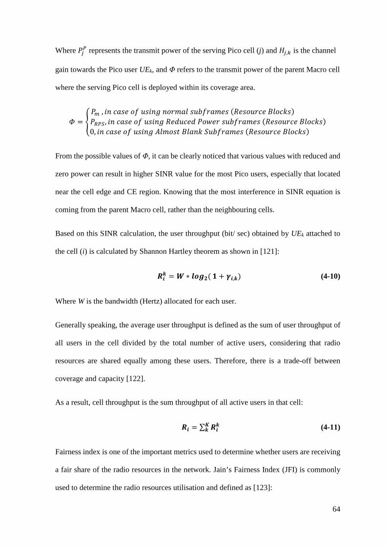
64
Where 𝑃𝑃𝑗𝑗𝑅𝑅 represents the transmit power of the serving Pico cell (j) and 𝐻𝐻𝑗𝑗,𝑘𝑘 is the channel
gain towards the Pico user UEk, and Φ refers to the transmit power of the parent Macro cell
where the serving Pico cell is deployed within its coverage area.
𝛷𝛷 = �𝑃𝑃𝑚𝑚 , 𝑖𝑖𝐼𝐼 𝑐𝑐𝑐𝑐𝑐𝑐𝑂𝑂 𝑙𝑙𝑖𝑖 𝑂𝑂𝑐𝑐𝑖𝑖𝐼𝐼𝑙𝑙 𝐼𝐼𝑙𝑙𝑂𝑂𝐾𝐾𝑐𝑐𝑙𝑙 𝑐𝑐𝑂𝑂𝑠𝑠𝑖𝑖𝑂𝑂𝑐𝑐𝐾𝐾𝑂𝑂𝑐𝑐 (𝑅𝑅𝑂𝑂𝑐𝑐𝑙𝑙𝑂𝑂𝑂𝑂𝑐𝑐𝑂𝑂 𝐵𝐵𝑙𝑙𝑙𝑙𝑐𝑐𝐵𝐵𝑐𝑐) 𝑃𝑃𝑅𝑅𝑅𝑅𝑅𝑅, 𝑖𝑖𝐼𝐼 𝑐𝑐𝑐𝑐𝑐𝑐𝑂𝑂 𝑙𝑙𝑖𝑖 𝑂𝑂𝑐𝑐𝑖𝑖𝐼𝐼𝑙𝑙 𝑅𝑅𝑂𝑂𝑅𝑅𝑂𝑂𝑐𝑐𝑂𝑂𝑅𝑅 𝑃𝑃𝑙𝑙𝑃𝑃𝑂𝑂𝑂𝑂 𝑐𝑐𝑂𝑂𝑠𝑠𝑖𝑖𝑂𝑂𝑐𝑐𝐾𝐾𝑂𝑂𝑐𝑐 (𝑅𝑅𝑂𝑂𝑐𝑐𝑙𝑙𝑂𝑂𝑂𝑂𝑐𝑐𝑂𝑂 𝐵𝐵𝑙𝑙𝑙𝑙𝑐𝑐𝐵𝐵𝑐𝑐)0, 𝑖𝑖𝐼𝐼 𝑐𝑐𝑐𝑐𝑐𝑐𝑂𝑂 𝑙𝑙𝑖𝑖 𝑂𝑂𝑐𝑐𝑖𝑖𝐼𝐼𝑙𝑙 𝐴𝐴𝑙𝑙𝐾𝐾𝑙𝑙𝑐𝑐𝑂𝑂 𝐵𝐵𝑙𝑙𝑐𝑐𝐼𝐼𝐵𝐵 𝑆𝑆𝑂𝑂𝑠𝑠𝑖𝑖𝑂𝑂𝑐𝑐𝐾𝐾𝑂𝑂𝑐𝑐 (𝑅𝑅𝑂𝑂𝑐𝑐𝑙𝑙𝑂𝑂𝑂𝑂𝑐𝑐𝑂𝑂 𝐵𝐵𝑙𝑙𝑙𝑙𝑐𝑐𝐵𝐵𝑐𝑐)
From the possible values of Φ, it can be clearly noticed that various values with reduced and
zero power can result in higher SINR value for the most Pico users, especially that located
near the cell edge and CE region. Knowing that the most interference in SINR equation is
coming from the parent Macro cell, rather than the neighbouring cells.
Based on this SINR calculation, the user throughput (bit/ sec) obtained by UEk attached to
the cell (i) is calculated by Shannon Hartley theorem as shown in [121]:
𝑹𝑹𝑺𝑺𝒌𝒌 = 𝑾𝑾 ∗ 𝒄𝒄𝒍𝒍𝑺𝑺𝟐𝟐(𝟏𝟏 + 𝜸𝜸𝑺𝑺,𝒌𝒌) (4-10)
Where W is the bandwidth (Hertz) allocated for each user.
Generally speaking, the average user throughput is defined as the sum of user throughput of
all users in the cell divided by the total number of active users, considering that radio
resources are shared equally among these users. Therefore, there is a trade-off between
coverage and capacity [122].
As a result, cell throughput is the sum throughput of all active users in that cell:
𝑹𝑹𝑺𝑺 = ∑ 𝑹𝑹𝑺𝑺𝒌𝒌𝑲𝑲𝒌𝒌 (4-11)
Fairness index is one of the important metrics used to determine whether users are receiving
a fair share of the radio resources in the network. Jain’s Fairness Index (JFI) is commonly
used to determine the radio resources utilisation and defined as [123]:
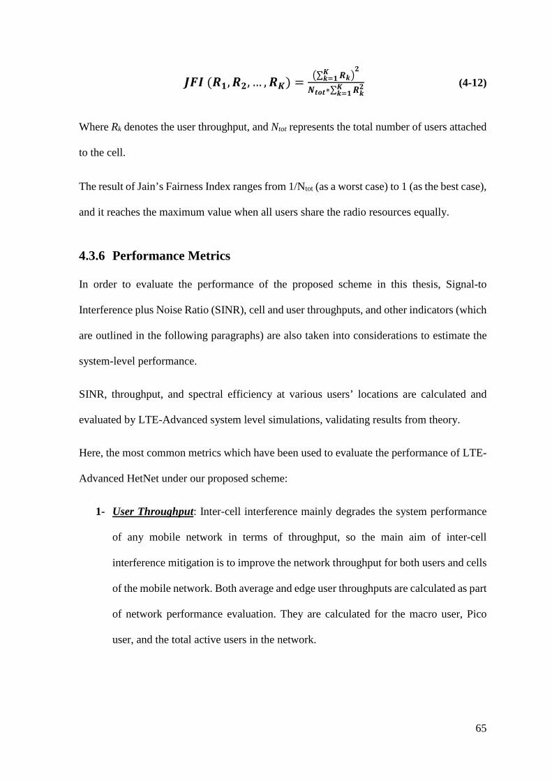
65
𝑱𝑱𝑱𝑱𝑰𝑰 (𝑹𝑹𝟏𝟏,𝑹𝑹𝟐𝟐, … ,𝑹𝑹𝑲𝑲) = �∑ 𝑹𝑹𝒌𝒌𝑲𝑲𝒌𝒌=𝟏𝟏 �
𝟐𝟐
𝑵𝑵𝒕𝒕𝒍𝒍𝒕𝒕∗∑ 𝑹𝑹𝒌𝒌𝟐𝟐𝑲𝑲
𝒌𝒌=𝟏𝟏 (4-12)
Where Rk denotes the user throughput, and Ntot represents the total number of users attached
to the cell.
The result of Jain’s Fairness Index ranges from 1/Ntot (as a worst case) to 1 (as the best case),
and it reaches the maximum value when all users share the radio resources equally.
4.3.6 Performance Metrics
In order to evaluate the performance of the proposed scheme in this thesis, Signal-to
Interference plus Noise Ratio (SINR), cell and user throughputs, and other indicators (which
are outlined in the following paragraphs) are also taken into considerations to estimate the
system-level performance.
SINR, throughput, and spectral efficiency at various users’ locations are calculated and
evaluated by LTE-Advanced system level simulations, validating results from theory.
Here, the most common metrics which have been used to evaluate the performance of LTE-
Advanced HetNet under our proposed scheme:
1- User Throughput: Inter-cell interference mainly degrades the system performance
of any mobile network in terms of throughput, so the main aim of inter-cell
interference mitigation is to improve the network throughput for both users and cells
of the mobile network. Both average and edge user throughputs are calculated as part
of network performance evaluation. They are calculated for the macro user, Pico
user, and the total active users in the network.
66
2- Cell Throughput: Considering the average and edge cell throughputs in terms of
macro cells, Pico cells, and the total cells in the network, respectively. Noting that,
the cell throughput equals the sum throughput for all attached users to the cell.
3- Average user spectral efficiency: Spectral Efficiency (SE) is one of the most
important metrics to take into consideration when evaluating any mobile network. In
our project, we considered spectrum efficiency for Macro, Pico, and total users in the
proposed network.
4- Average RBs/ TTI/ UE: In every Transmission Time Interval (TTI), the average
number of Resource Blocks (RBs) allocated for each user is considered a significant
metric to show the advantages of the scheduling algorithms.
5- Fairness index among UEs: Any user in the network should get a relatively fair
share of the available resources, to ensure sufficient experience as compared to the
rest of users.
6- Number of offloaded users for each CRE value: It indicates the number of offloaded
users towards the Pico cells when for each range expansion value (0, 3, 6, 9, 12, 15),
to evaluate the impact of Cell Range Expansion (CRE) on the other performance
metrics.
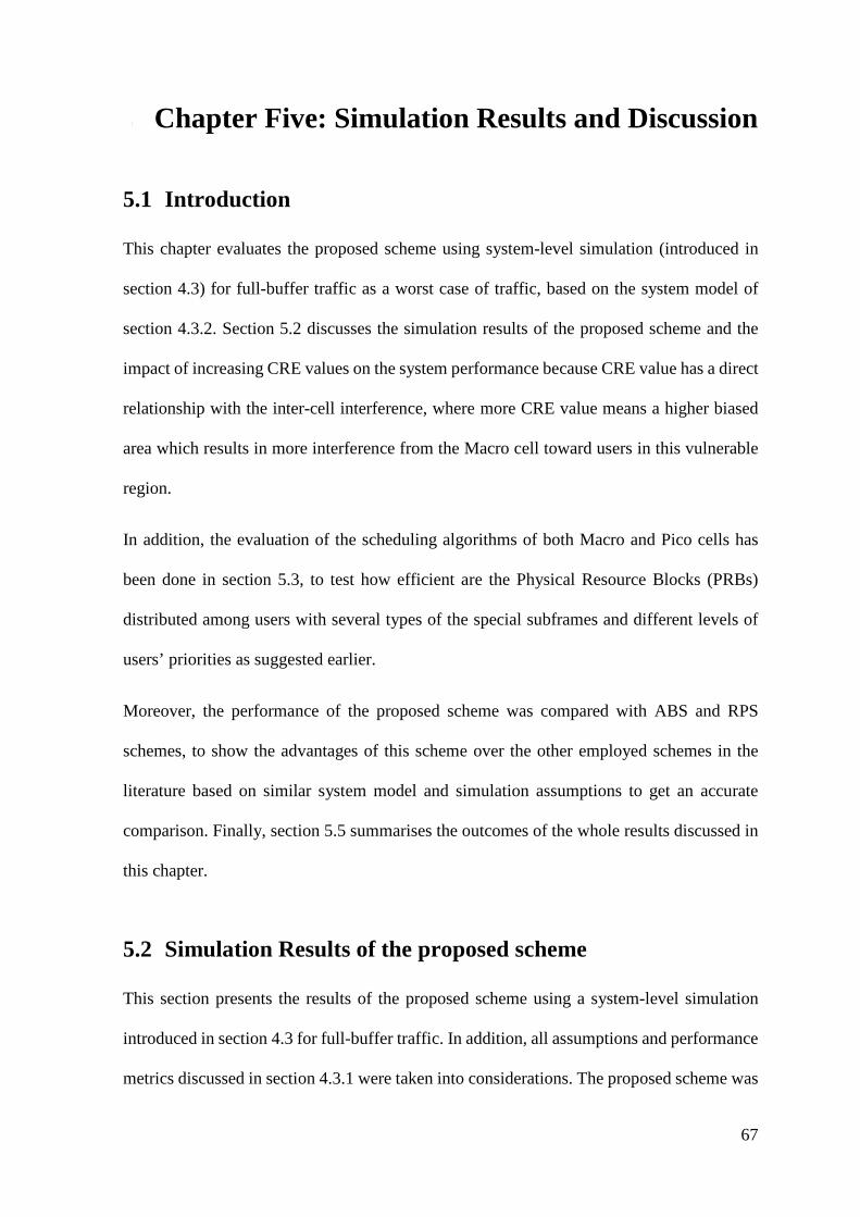
67
5 Chapter Five: Simulation Results and Discussion
5.1 Introduction
This chapter evaluates the proposed scheme using system-level simulation (introduced in
section 4.3) for full-buffer traffic as a worst case of traffic, based on the system model of
section 4.3.2. Section 5.2 discusses the simulation results of the proposed scheme and the
impact of increasing CRE values on the system performance because CRE value has a direct
relationship with the inter-cell interference, where more CRE value means a higher biased
area which results in more interference from the Macro cell toward users in this vulnerable
region.
In addition, the evaluation of the scheduling algorithms of both Macro and Pico cells has
been done in section 5.3, to test how efficient are the Physical Resource Blocks (PRBs)
distributed among users with several types of the special subframes and different levels of
users’ priorities as suggested earlier.
Moreover, the performance of the proposed scheme was compared with ABS and RPS
schemes, to show the advantages of this scheme over the other employed schemes in the
literature based on similar system model and simulation assumptions to get an accurate
comparison. Finally, section 5.5 summarises the outcomes of the whole results discussed in
this chapter.
5.2 Simulation Results of the proposed scheme
This section presents the results of the proposed scheme using a system-level simulation
introduced in section 4.3 for full-buffer traffic. In addition, all assumptions and performance
metrics discussed in section 4.3.1 were taken into considerations. The proposed scheme was
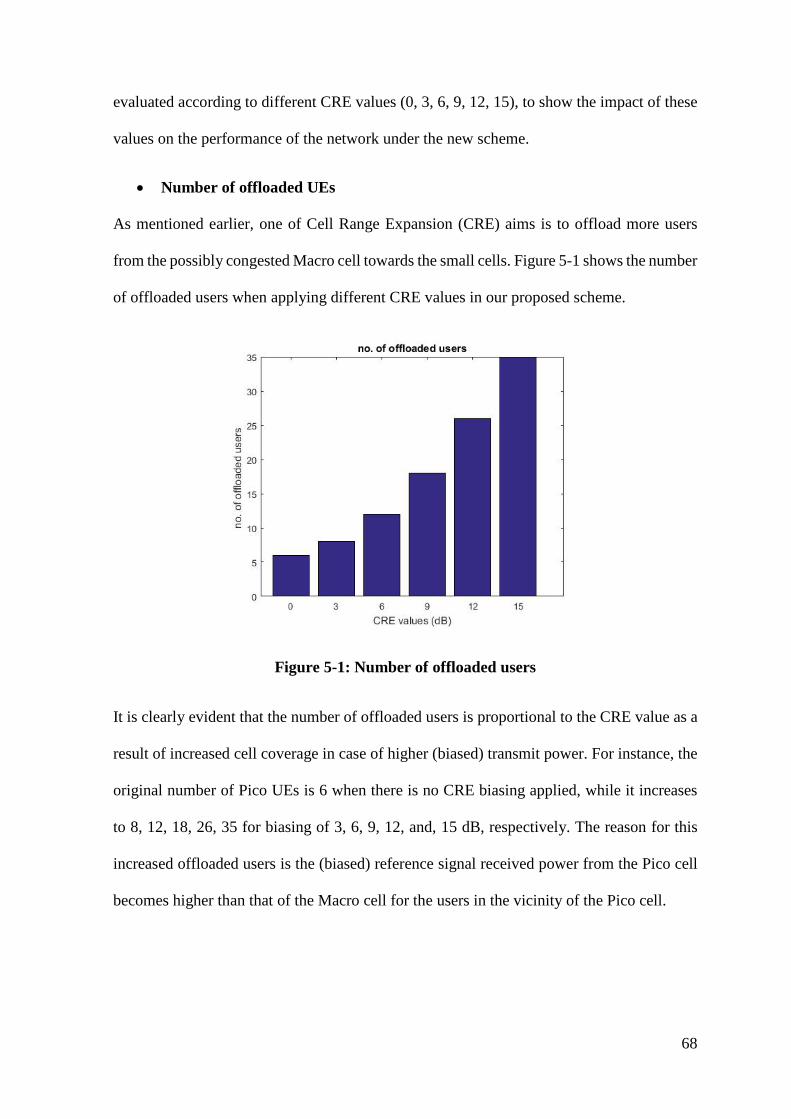
68
evaluated according to different CRE values (0, 3, 6, 9, 12, 15), to show the impact of these
values on the performance of the network under the new scheme.
• Number of offloaded UEs
As mentioned earlier, one of Cell Range Expansion (CRE) aims is to offload more users
from the possibly congested Macro cell towards the small cells. Figure 5-1 shows the number
of offloaded users when applying different CRE values in our proposed scheme.
Figure 5-1: Number of offloaded users
It is clearly evident that the number of offloaded users is proportional to the CRE value as a
result of increased cell coverage in case of higher (biased) transmit power. For instance, the
original number of Pico UEs is 6 when there is no CRE biasing applied, while it increases
to 8, 12, 18, 26, 35 for biasing of 3, 6, 9, 12, and, 15 dB, respectively. The reason for this
increased offloaded users is the (biased) reference signal received power from the Pico cell
becomes higher than that of the Macro cell for the users in the vicinity of the Pico cell.
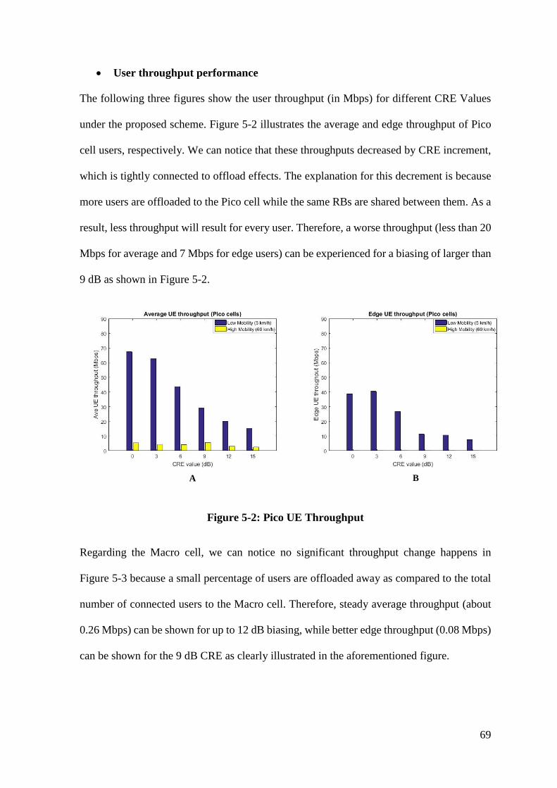
69
• User throughput performance
The following three figures show the user throughput (in Mbps) for different CRE Values
under the proposed scheme. Figure 5-2 illustrates the average and edge throughput of Pico
cell users, respectively. We can notice that these throughputs decreased by CRE increment,
which is tightly connected to offload effects. The explanation for this decrement is because
more users are offloaded to the Pico cell while the same RBs are shared between them. As a
result, less throughput will result for every user. Therefore, a worse throughput (less than 20
Mbps for average and 7 Mbps for edge users) can be experienced for a biasing of larger than
9 dB as shown in Figure 5-2.
BA
Figure 5-2: Pico UE Throughput
Regarding the Macro cell, we can notice no significant throughput change happens in
Figure 5-3 because a small percentage of users are offloaded away as compared to the total
number of connected users to the Macro cell. Therefore, steady average throughput (about
0.26 Mbps) can be shown for up to 12 dB biasing, while better edge throughput (0.08 Mbps)
can be shown for the 9 dB CRE as clearly illustrated in the aforementioned figure.
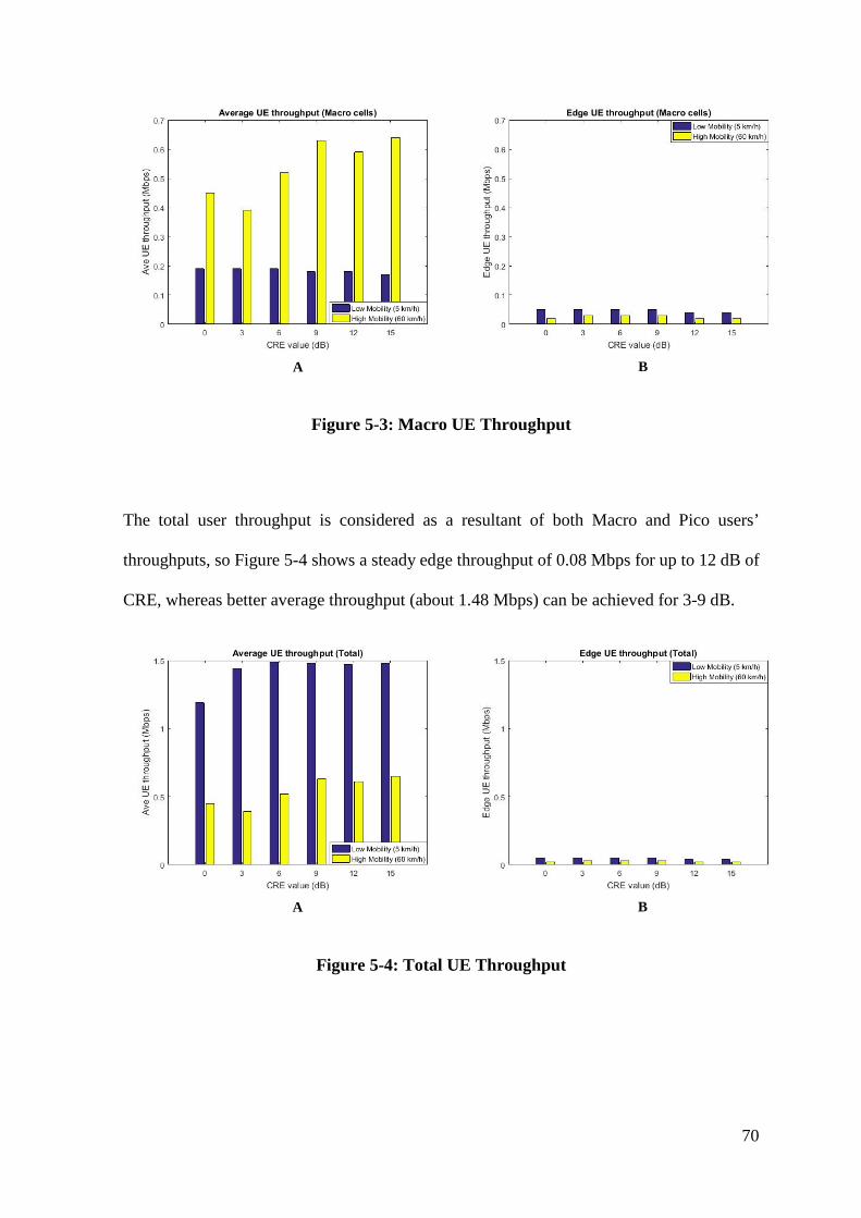
70
BA
Figure 5-3: Macro UE Throughput
The total user throughput is considered as a resultant of both Macro and Pico users’
throughputs, so Figure 5-4 shows a steady edge throughput of 0.08 Mbps for up to 12 dB of
CRE, whereas better average throughput (about 1.48 Mbps) can be achieved for 3-9 dB.
BA
Figure 5-4: Total UE Throughput
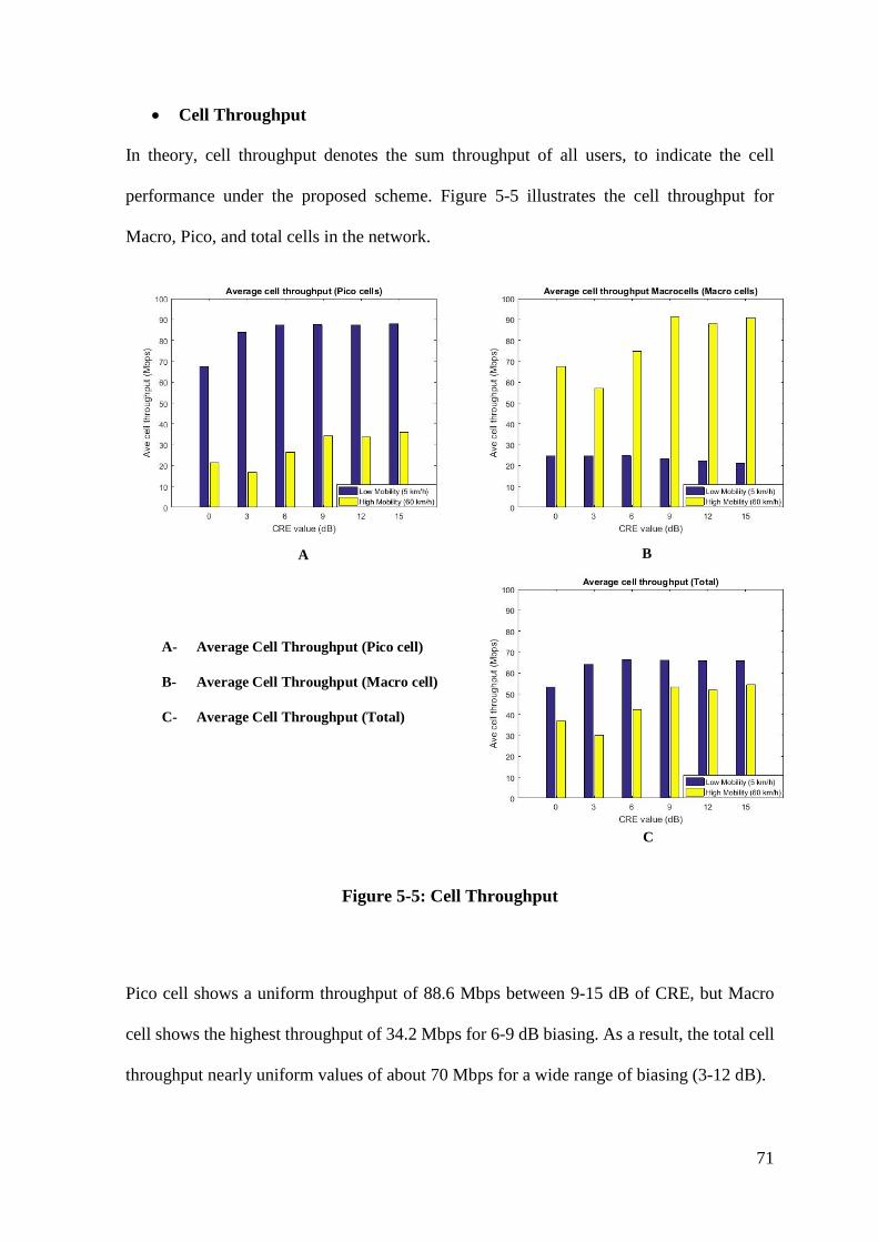
71
• Cell Throughput
In theory, cell throughput denotes the sum throughput of all users, to indicate the cell
performance under the proposed scheme. Figure 5-5 illustrates the cell throughput for
Macro, Pico, and total cells in the network.
A B
C
A- Average Cell Throughput (Pico cell)
B- Average Cell Throughput (Macro cell)
C- Average Cell Throughput (Total)
Figure 5-5: Cell Throughput
Pico cell shows a uniform throughput of 88.6 Mbps between 9-15 dB of CRE, but Macro
cell shows the highest throughput of 34.2 Mbps for 6-9 dB biasing. As a result, the total cell
throughput nearly uniform values of about 70 Mbps for a wide range of biasing (3-12 dB).
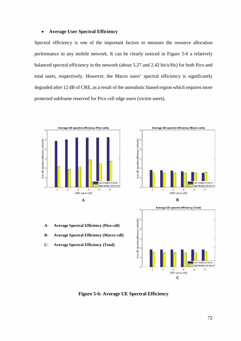
72
• Average User Spectral Efficiency
Spectral efficiency is one of the important factors to measure the resource allocation
performance in any mobile network. It can be clearly noticed in Figure 5-6 a relatively
balanced spectral efficiency in the network (about 5.27 and 2.42 bit/s/Hz) for both Pico and
total users, respectively. However, the Macro users’ spectral efficiency is significantly
degraded after 12 dB of CRE, as a result of the unrealistic biased region which requires more
protected subframe reserved for Pico cell edge users (victim users).
A B
C
A- Average Spectral Efficiency (Pico cell)
B- Average Spectral Efficiency (Macro cell)
C- Average Spectral Efficiency (Total)
Figure 5-6: Average UE Spectral Efficiency
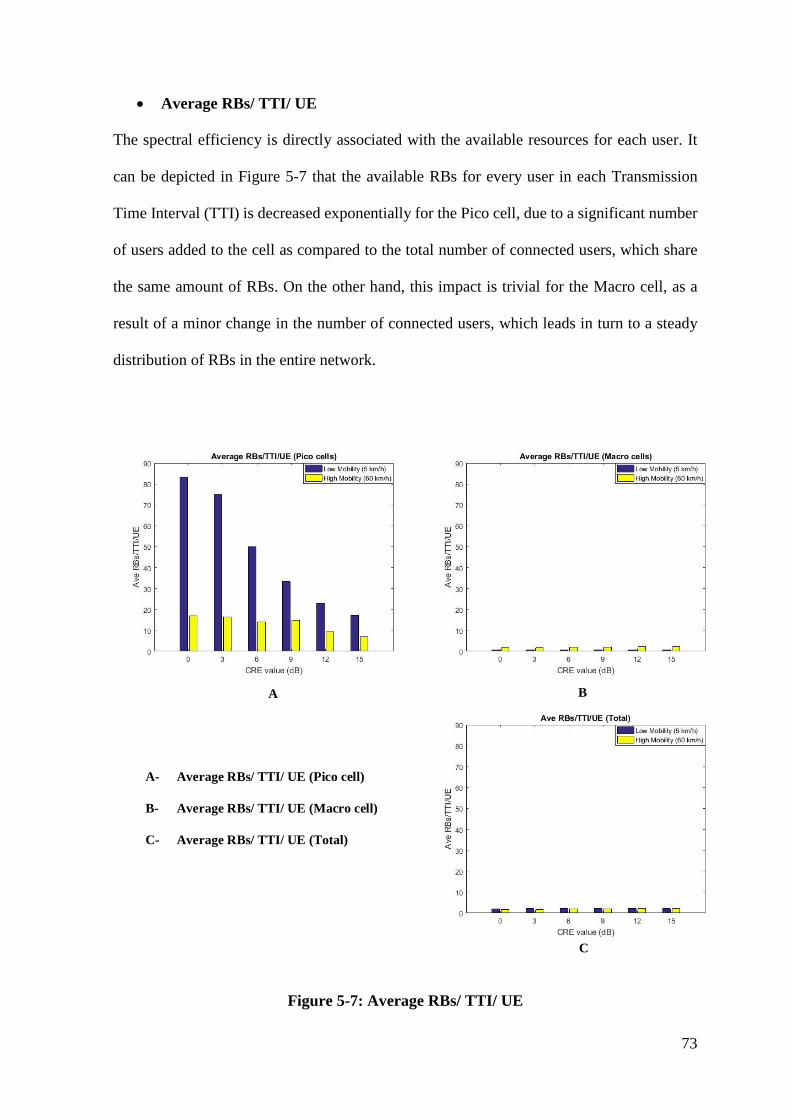
73
• Average RBs/ TTI/ UE
The spectral efficiency is directly associated with the available resources for each user. It
can be depicted in Figure 5-7 that the available RBs for every user in each Transmission
Time Interval (TTI) is decreased exponentially for the Pico cell, due to a significant number
of users added to the cell as compared to the total number of connected users, which share
the same amount of RBs. On the other hand, this impact is trivial for the Macro cell, as a
result of a minor change in the number of connected users, which leads in turn to a steady
distribution of RBs in the entire network.
A B
C
A- Average RBs/ TTI/ UE (Pico cell)
B- Average RBs/ TTI/ UE (Macro cell)
C- Average RBs/ TTI/ UE (Total)
Figure 5-7: Average RBs/ TTI/ UE

74
• Fairness among Users
Jain’s fairness index (mentioned in section 4.3.5) is considered to evaluate how much fair
resources every user gets when employing the proposed scheme. Figure 5-8 illustrates the
fairness index for Pico, Macro, and total users, respectively.
BA
Figure 5-8: Fairness Index among UEs
It can show a relatively uniform index among all Macro users, while an alternating index for
Pico users. However, fairness index for the total users shows better fairness when increasing
the CRE value, which is considered a merit of the scheduling algorithm under the proposed
scheme.
5.3 Evaluation of the Scheduling Algorithms
The proposed scheme highly requires powerful priority scheduling algorithms for efficient
resource allocation of all users in the network. The reason behind this, we have several types
of special subframes and users of different priorities. These algorithms for both Macro cell
and Pico cells have been evaluated using system-level simulation to show the importance of
such algorithms in this scheme, by comparing the network performance when using these
algorithms to that case when the ordinary proportion fairness scheduler is used.
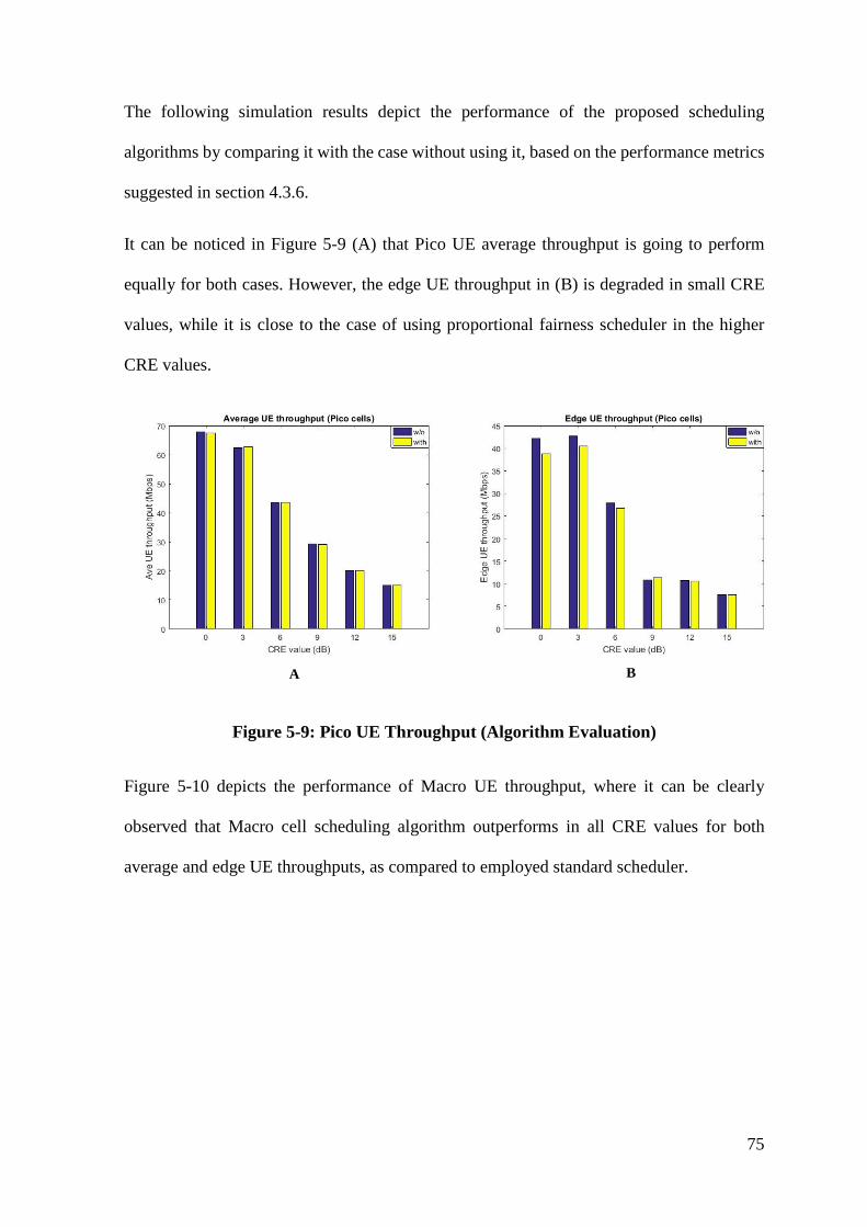
75
The following simulation results depict the performance of the proposed scheduling
algorithms by comparing it with the case without using it, based on the performance metrics
suggested in section 4.3.6.
It can be noticed in Figure 5-9 (A) that Pico UE average throughput is going to perform
equally for both cases. However, the edge UE throughput in (B) is degraded in small CRE
values, while it is close to the case of using proportional fairness scheduler in the higher
CRE values.
A B
Figure 5-9: Pico UE Throughput (Algorithm Evaluation)
Figure 5-10 depicts the performance of Macro UE throughput, where it can be clearly
observed that Macro cell scheduling algorithm outperforms in all CRE values for both
average and edge UE throughputs, as compared to employed standard scheduler.
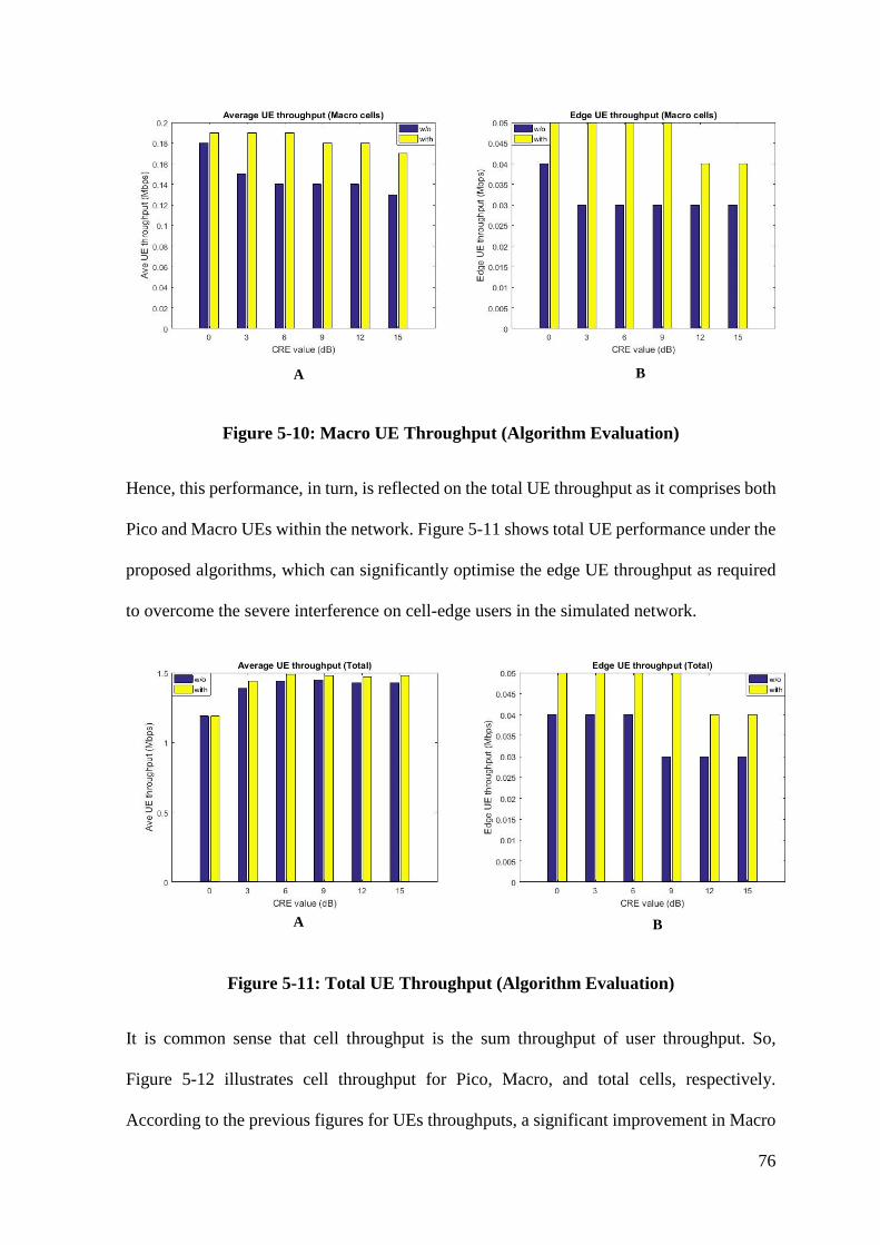
76
A B
Figure 5-10: Macro UE Throughput (Algorithm Evaluation)
Hence, this performance, in turn, is reflected on the total UE throughput as it comprises both
Pico and Macro UEs within the network. Figure 5-11 shows total UE performance under the
proposed algorithms, which can significantly optimise the edge UE throughput as required
to overcome the severe interference on cell-edge users in the simulated network.
A B
Figure 5-11: Total UE Throughput (Algorithm Evaluation)
It is common sense that cell throughput is the sum throughput of user throughput. So,
Figure 5-12 illustrates cell throughput for Pico, Macro, and total cells, respectively.
According to the previous figures for UEs throughputs, a significant improvement in Macro
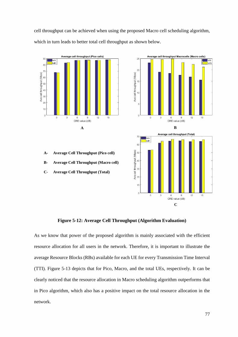
77
cell throughput can be achieved when using the proposed Macro cell scheduling algorithm,
which in turn leads to better total cell throughput as shown below.
A B
C
A- Average Cell Throughput (Pico cell)
B- Average Cell Throughput (Macro cell)
C- Average Cell Throughput (Total)
Figure 5-12: Average Cell Throughput (Algorithm Evaluation)
As we know that power of the proposed algorithm is mainly associated with the efficient
resource allocation for all users in the network. Therefore, it is important to illustrate the
average Resource Blocks (RBs) available for each UE for every Transmission Time Interval
(TTI). Figure 5-13 depicts that for Pico, Macro, and the total UEs, respectively. It can be
clearly noticed that the resource allocation in Macro scheduling algorithm outperforms that
in Pico algorithm, which also has a positive impact on the total resource allocation in the
network.
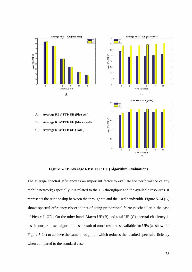
78
A B
C
A- Average RBs/ TTI/ UE (Pico cell)
B- Average RBs/ TTI/ UE (Macro cell)
C- Average RBs/ TTI/ UE (Total)
Figure 5-13: Average RBs/ TTI/ UE (Algorithm Evaluation)
The average spectral efficiency is an important factor to evaluate the performance of any
mobile network; especially it is related to the UE throughput and the available resources. It
represents the relationship between the throughput and the used bandwidth. Figure 5-14 (A)
shows spectral efficiency closer to that of using proportional fairness scheduler in the case
of Pico cell UEs. On the other hand, Macro UE (B) and total UE (C) spectral efficiency is
less in our proposed algorithm, as a result of more resources available for UEs (as shown in
Figure 5-14) to achieve the same throughput, which reduces the resulted spectral efficiency
when compared to the standard case.
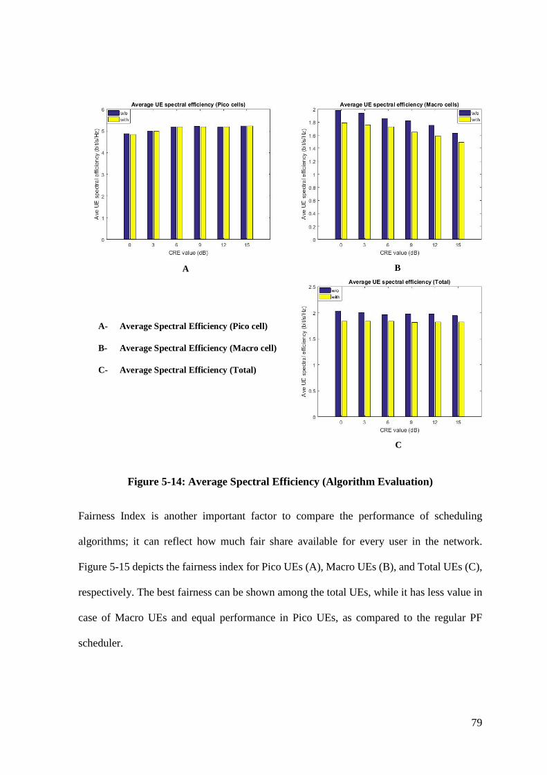
79
A B
C
A- Average Spectral Efficiency (Pico cell)
B- Average Spectral Efficiency (Macro cell)
C- Average Spectral Efficiency (Total)
Figure 5-14: Average Spectral Efficiency (Algorithm Evaluation)
Fairness Index is another important factor to compare the performance of scheduling
algorithms; it can reflect how much fair share available for every user in the network.
Figure 5-15 depicts the fairness index for Pico UEs (A), Macro UEs (B), and Total UEs (C),
respectively. The best fairness can be shown among the total UEs, while it has less value in
case of Macro UEs and equal performance in Pico UEs, as compared to the regular PF
scheduler.
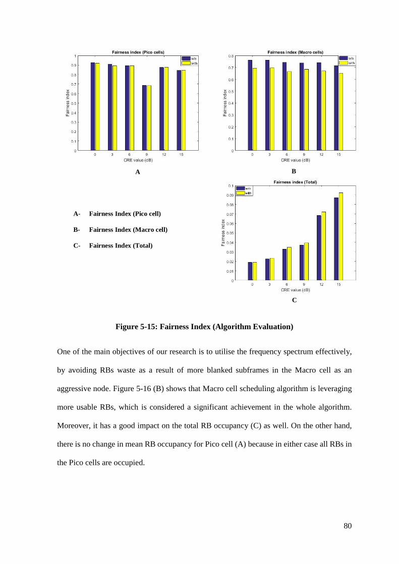
80
A B
C
A- Fairness Index (Pico cell)
B- Fairness Index (Macro cell)
C- Fairness Index (Total)
Figure 5-15: Fairness Index (Algorithm Evaluation)
One of the main objectives of our research is to utilise the frequency spectrum effectively,
by avoiding RBs waste as a result of more blanked subframes in the Macro cell as an
aggressive node. Figure 5-16 (B) shows that Macro cell scheduling algorithm is leveraging
more usable RBs, which is considered a significant achievement in the whole algorithm.
Moreover, it has a good impact on the total RB occupancy (C) as well. On the other hand,
there is no change in mean RB occupancy for Pico cell (A) because in either case all RBs in
the Pico cells are occupied.
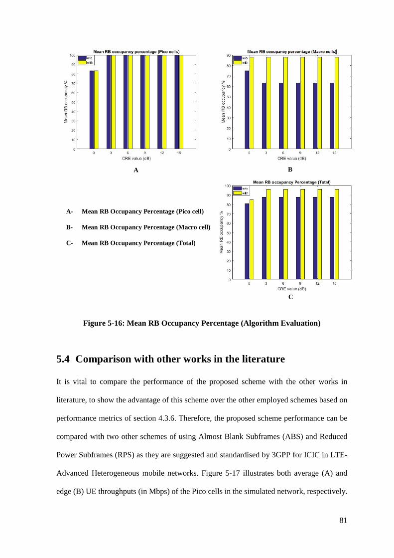
81
A B
C
A- Mean RB Occupancy Percentage (Pico cell)
B- Mean RB Occupancy Percentage (Macro cell)
C- Mean RB Occupancy Percentage (Total)
Figure 5-16: Mean RB Occupancy Percentage (Algorithm Evaluation)
5.4 Comparison with other works in the literature
It is vital to compare the performance of the proposed scheme with the other works in
literature, to show the advantage of this scheme over the other employed schemes based on
performance metrics of section 4.3.6. Therefore, the proposed scheme performance can be
compared with two other schemes of using Almost Blank Subframes (ABS) and Reduced
Power Subframes (RPS) as they are suggested and standardised by 3GPP for ICIC in LTE-
Advanced Heterogeneous mobile networks. Figure 5-17 illustrates both average (A) and
edge (B) UE throughputs (in Mbps) of the Pico cells in the simulated network, respectively.
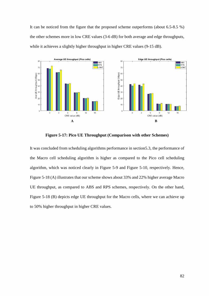
82
It can be noticed from the figure that the proposed scheme outperforms (about 6.5-8.5 %)
the other schemes more in low CRE values (3-6 dB) for both average and edge throughputs,
while it achieves a slightly higher throughput in higher CRE values (9-15 dB).
BA
Figure 5-17: Pico UE Throughput (Comparison with other Schemes)
It was concluded from scheduling algorithms performance in section5.3, the performance of
the Macro cell scheduling algorithm is higher as compared to the Pico cell scheduling
algorithm, which was noticed clearly in Figure 5-9 and Figure 5-10, respectively. Hence,
Figure 5-18 (A) illustrates that our scheme shows about 33% and 22% higher average Macro
UE throughput, as compared to ABS and RPS schemes, respectively. On the other hand,
Figure 5-18 (B) depicts edge UE throughput for the Macro cells, where we can achieve up
to 50% higher throughput in higher CRE values.
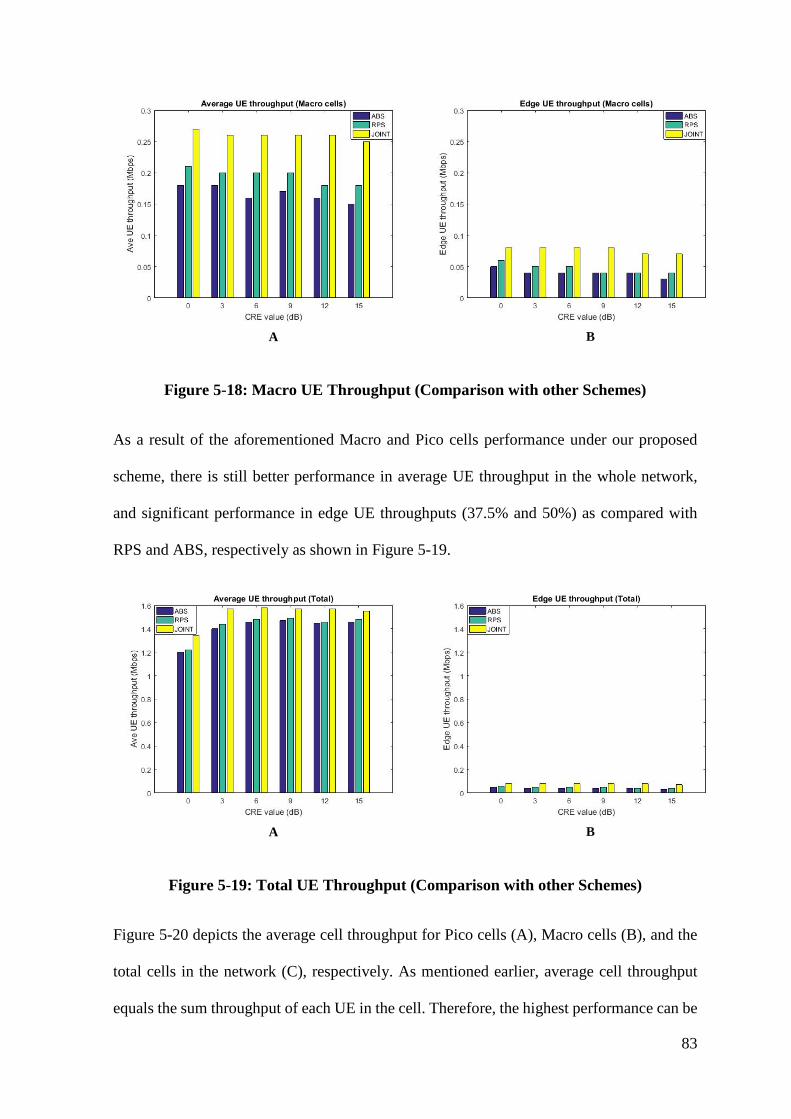
83
BA
Figure 5-18: Macro UE Throughput (Comparison with other Schemes)
As a result of the aforementioned Macro and Pico cells performance under our proposed
scheme, there is still better performance in average UE throughput in the whole network,
and significant performance in edge UE throughputs (37.5% and 50%) as compared with
RPS and ABS, respectively as shown in Figure 5-19.
BA
Figure 5-19: Total UE Throughput (Comparison with other Schemes)
Figure 5-20 depicts the average cell throughput for Pico cells (A), Macro cells (B), and the
total cells in the network (C), respectively. As mentioned earlier, average cell throughput
equals the sum throughput of each UE in the cell. Therefore, the highest performance can be
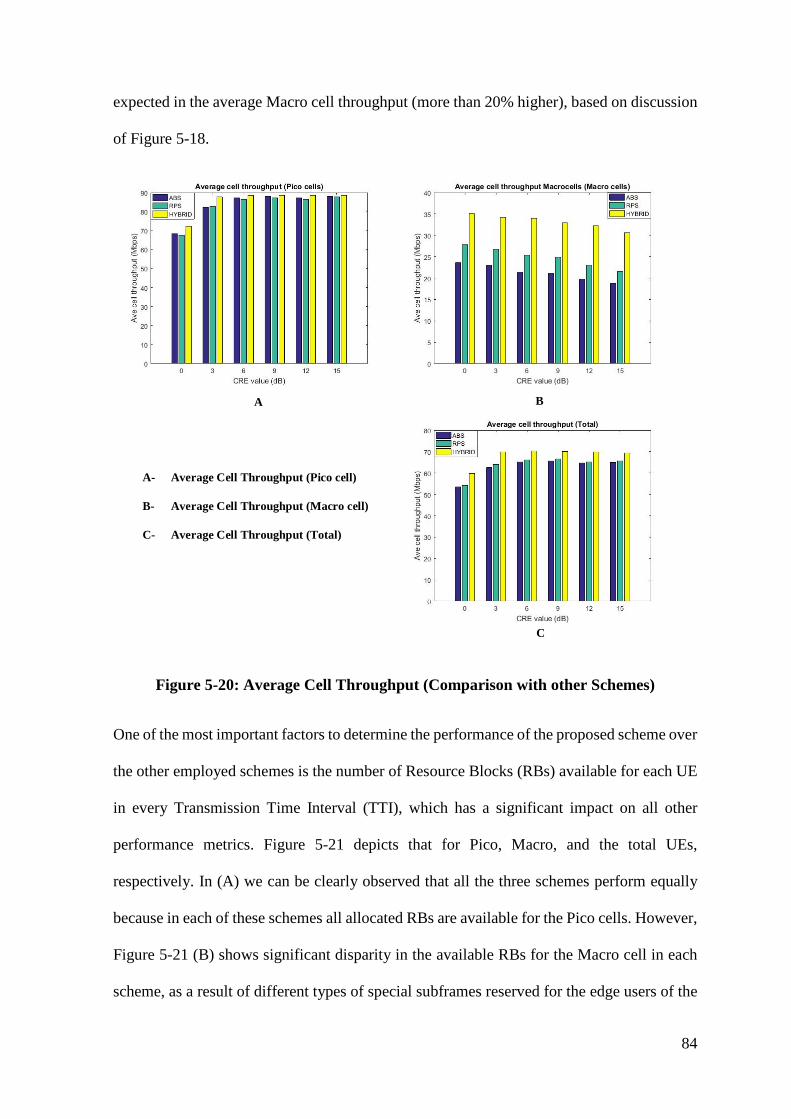
84
expected in the average Macro cell throughput (more than 20% higher), based on discussion
of Figure 5-18.
A B
C
A- Average Cell Throughput (Pico cell)
B- Average Cell Throughput (Macro cell)
C- Average Cell Throughput (Total)
Figure 5-20: Average Cell Throughput (Comparison with other Schemes)
One of the most important factors to determine the performance of the proposed scheme over
the other employed schemes is the number of Resource Blocks (RBs) available for each UE
in every Transmission Time Interval (TTI), which has a significant impact on all other
performance metrics. Figure 5-21 depicts that for Pico, Macro, and the total UEs,
respectively. In (A) we can be clearly observed that all the three schemes perform equally
because in each of these schemes all allocated RBs are available for the Pico cells. However,
Figure 5-21 (B) shows significant disparity in the available RBs for the Macro cell in each
scheme, as a result of different types of special subframes reserved for the edge users of the
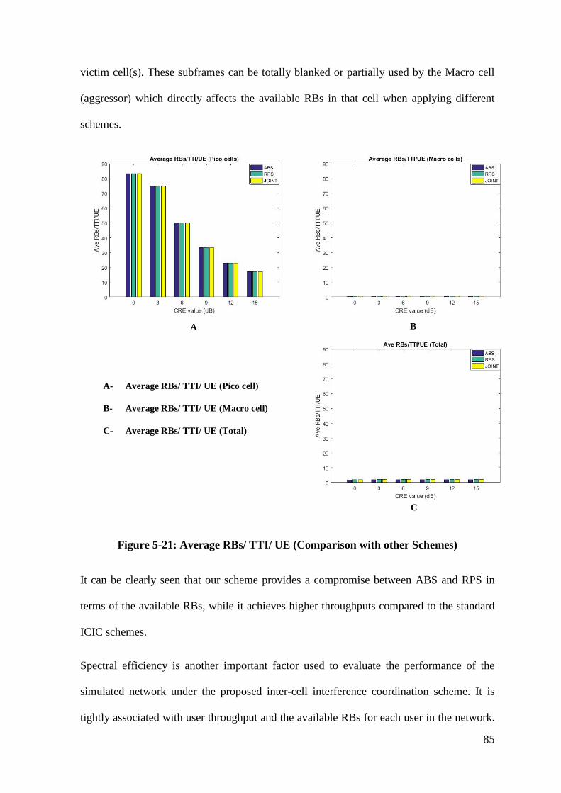
85
victim cell(s). These subframes can be totally blanked or partially used by the Macro cell
(aggressor) which directly affects the available RBs in that cell when applying different
schemes.
A B
C
A- Average RBs/ TTI/ UE (Pico cell)
B- Average RBs/ TTI/ UE (Macro cell)
C- Average RBs/ TTI/ UE (Total)
Figure 5-21: Average RBs/ TTI/ UE (Comparison with other Schemes)
It can be clearly seen that our scheme provides a compromise between ABS and RPS in
terms of the available RBs, while it achieves higher throughputs compared to the standard
ICIC schemes.
Spectral efficiency is another important factor used to evaluate the performance of the
simulated network under the proposed inter-cell interference coordination scheme. It is
tightly associated with user throughput and the available RBs for each user in the network.
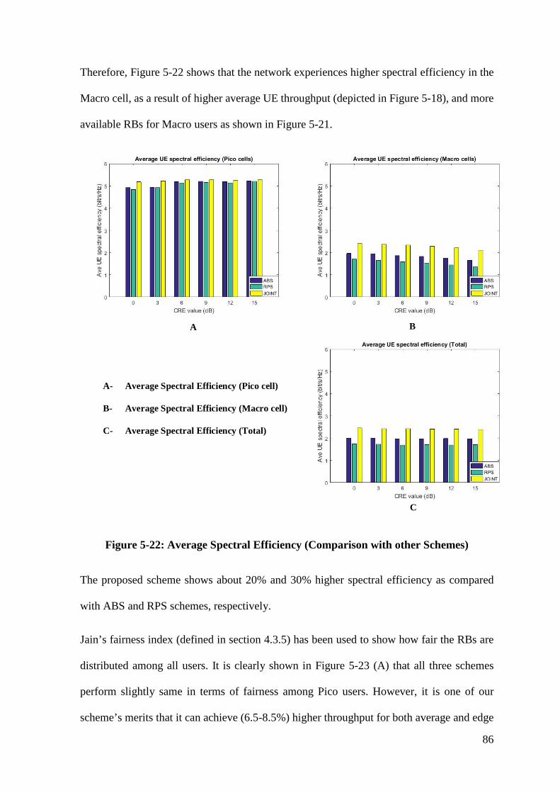
86
Therefore, Figure 5-22 shows that the network experiences higher spectral efficiency in the
Macro cell, as a result of higher average UE throughput (depicted in Figure 5-18), and more
available RBs for Macro users as shown in Figure 5-21.
A B
C
A- Average Spectral Efficiency (Pico cell)
B- Average Spectral Efficiency (Macro cell)
C- Average Spectral Efficiency (Total)
Figure 5-22: Average Spectral Efficiency (Comparison with other Schemes)
The proposed scheme shows about 20% and 30% higher spectral efficiency as compared
with ABS and RPS schemes, respectively.
Jain’s fairness index (defined in section 4.3.5) has been used to show how fair the RBs are
distributed among all users. It is clearly shown in Figure 5-23 (A) that all three schemes
perform slightly same in terms of fairness among Pico users. However, it is one of our
scheme’s merits that it can achieve (6.5-8.5%) higher throughput for both average and edge
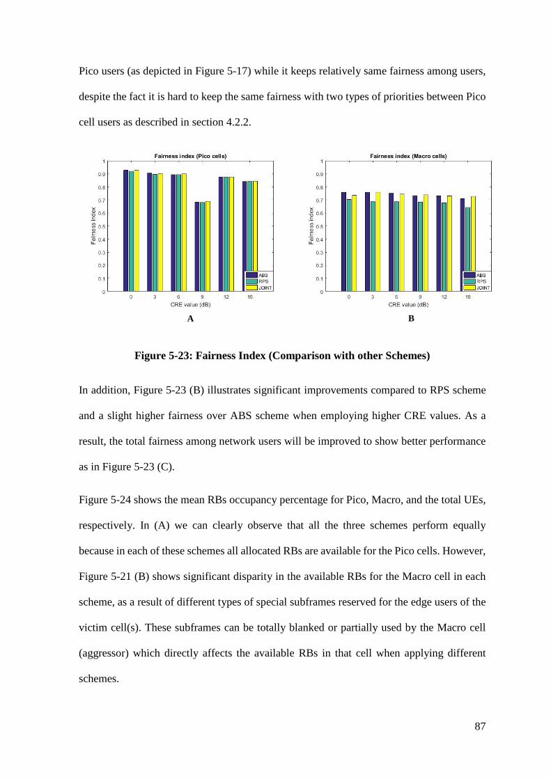
87
Pico users (as depicted in Figure 5-17) while it keeps relatively same fairness among users,
despite the fact it is hard to keep the same fairness with two types of priorities between Pico
cell users as described in section 4.2.2.
BA
Figure 5-23: Fairness Index (Comparison with other Schemes)
In addition, Figure 5-23 (B) illustrates significant improvements compared to RPS scheme
and a slight higher fairness over ABS scheme when employing higher CRE values. As a
result, the total fairness among network users will be improved to show better performance
as in Figure 5-23 (C).
Figure 5-24 shows the mean RBs occupancy percentage for Pico, Macro, and the total UEs,
respectively. In (A) we can clearly observe that all the three schemes perform equally
because in each of these schemes all allocated RBs are available for the Pico cells. However,
Figure 5-21 (B) shows significant disparity in the available RBs for the Macro cell in each
scheme, as a result of different types of special subframes reserved for the edge users of the
victim cell(s). These subframes can be totally blanked or partially used by the Macro cell
(aggressor) which directly affects the available RBs in that cell when applying different
schemes.

88
A B
C
A- Mean RB Occupancy Percentage (Pico cell)
B- Mean RB Occupancy Percentage (Macro cell)
C- Mean RB Occupancy Percentage (Total)
Figure 5-24: Mean RB Occupancy Percentage (Comparison with other Schemes)
89
5.5 Discussion
This section discusses the simulation results of the proposed inter-cell interference
mitigation scheme in LTE-Advanced as an example of OFDMA cellular network. It aims to
improve the performance of heterogeneous deployment of LTE-Advanced in terms of user
throughput (both average and edge users), cell throughput, spectral efficiency, fairness
among users, and the mean resource blocks occupancy for all cell as performance metrics.
Conventionally, increasing the CRE value results in degradation of throughput for the UEs
in Range Expanded (RE) region, as a result of the severe interference coming from Macro
cell towards these users.
However, it can be concluded that the proposed scheme can offer higher CRE without having
a negative impact on the network performance, thanks to the variety of special subframes
used to protect these vulnerable users while yielding of offloading more users to the small
cells to balance the load among all cells.
By using this scheme, simulation results show optimum radio resources utilisation for Macro
users’ throughput in both average and edge users. Likewise, the Macro cell throughput
behaves the same because it represents the sum throughput of all users in their coverage area.
On the other hand, the Pico users do not experience significant improvements as it has been
already protected by using the special subframes since the first ICIC schemes.
When comparing the proposed ICI mitigation scheme with both ABS and RPS schemes,
higher scheduling opportunities can be achieved for the Macro users/ cells (up to 50% as
compared with ABS), which leads to higher cell throughput as a result.
The proposed scheme shows about 20% and 30% higher spectral efficiencies in Macro users
as compared with ABS and RPS schemes, respectively.
90
Regarding the impact of CRE increments on the network performance under the proposed
scheme:
• The number of offloaded users toward the Pico cells is proportional to the
CRE value as a result of increased (biased) cell coverage.
• Pico user throughput decreased because more offloaded users will share the
same radio resources, which has a direct impact on the cell throughput. In
contrast, Macro cell does not experience significant change because the
percentage of offloaded users is still trivial as compared to the total number
of connected users.
• Worse Pico user throughput can be experienced for a biasing of larger than 9
dB, and steady Macro user throughput for up to 12 dB biasing.
• Pico user throughput performs equally in high CRE values as compared with
the case of using only proportional fairness scheduler, while it clearly shows
higher performance in all CRE values for both average and cell-edge Macro
user throughput as compared to the standard scheduler.
It is vital to compare the performance of the proposed scheme with other TD-ICIC schemes
to show the advantages of this scheme as part of the proposal evaluation. Therefore, the
comparison with ABS and RPS can be summarised as follows:
• the proposed scheme outperforms (about 6.5-8.5 %) the other schemes more in
low CRE values (3-6 dB) for both average and edge throughputs of the Pico cells,
while it achieves a slightly higher throughput in higher CRE values (9-15 dB).
• 33% and 22% higher average Macro UE throughput, as compared to ABS and
RPS schemes, respectively. Also, the edge UE throughput for the Macro cells can
achieve up to 50% higher throughput in higher CRE values.
91
• As a result of the aforementioned Macro and Pico cells performance under our
proposed scheme, there is still better performance in average UE throughput in
the whole network, and significant performance in edge UE throughputs (37.5%
and 50%) as compared with RPS and ABS, respectively.
• As mentioned earlier, average cell throughput equals the sum throughput of each
UE in the cell. Therefore, the highest performance can be expected in the average
Macro cell throughput, which in turn has a positive impact on the average cell
throughput of the whole network.
As a conclusion, simulation results of the proposed scheme show optimum radio resources
utilisation for Macro users’ throughput in both average and edge users. Likewise, the Macro
cell throughput behaves the same because it represents the sum throughput of all users in
their coverage area.
On the other hand, the Pico users do not experience significant improvements as it has been
already protected by using the special subframes since the first ICIC schemes.
When comparing the proposed ICI mitigation scheme with both ABS and RPS schemes,
higher scheduling opportunities can be achieved for the Macro users/ cells (up to 50% as
compared with ABS), which leads to higher cell throughput as a result. The proposed scheme
shows about 20% and 30% higher spectral efficiencies in Macro users as compared with
ABS and RPS schemes, respectively.

92
5.6 Summary
Chapter 5 evaluates the proposed scheme using system-level simulation, based on the system
model of section 4.3.2. It mainly investigates the simulation results of the proposed scheme
and the impact of increasing CRE values on the system performance as a consequence of the
direct relationship with the ICI. Furthermore, section 5.3 discusses the evaluation of the
priority scheduling algorithms on both Macro and Pico cells, to test how efficient are the
RBs distributed among users with different levels of priorities and several types of radio
resources. After that, the performance of the proposed scheme was compared with the other
TD-ICIC configurations (section 5.4) to show the advantages over the other employed
schemes based on the similar system model and simulation assumptions to get an accurate
comparison. Finally, section 5.5 outlines the discussion of the simulation results obtained by
the system-level simulation of the whole chapter.
93
6 Chapter Six: Conclusions and Future Work This thesis investigates the interference mitigation in LTE-Advanced Heterogeneous
Networks (HetNets) and contributes to mitigating the inter-cell interference (ICI) in macro
cell- Pico cell scenarios. It provides increased downlink network performance in terms of
user and cell throughputs, which results in total network improvements. The next subsections
summarise the research contribution of this thesis and give a direction for the future work.
6.1 Summary of Thesis Contribution
Despite the significant benefits of deploying LTE-Advanced HetNets to increase the network
capacity or to extend the coverage in a cost-effective way, Inter-cell interference is one of
the largest challenges in such networks when utilising co-channel deployment. This type of
interference results from the transmit power disparity in cells of different classes. On one
hand, Cell Range Expansion (CRE) concept has been already employed to solve the uplink
ICI, and to offload more data connections toward the Low-Power Cells (LPCs), achieving
higher load balance in LTE-A HetNets. On the other hand, several types of ICIC schemes
have been utilised to mitigate the downlink ICI. These schemes have been classified into
Power-Domain (PD-ICIC), Coordinated Multipoint (CoMP), Frequency-Domain (FD-
ICIC), and Time-Domain (TD-ICIC). In the light of this, the latter scheme has been chosen
for further improvements in this thesis as a result of its higher spectral utilisation by sharing
the whole available bandwidth between the Macro cell and the LPCs, and the capability of
employing higher CRE values which in some cases are necessary to achieve proper load
balance in the HetNets. The key design of TD-ICIC relies on reducing the transmission
activity on certain subframes of the aggressor cell (e.g. Macro cell), to provide protected
subframes to schedule the data of the cell-edge users of the victim cell (e.g. Pico cell).
Therefore, these subframes could be totally blanked from user data in the aggressor cell
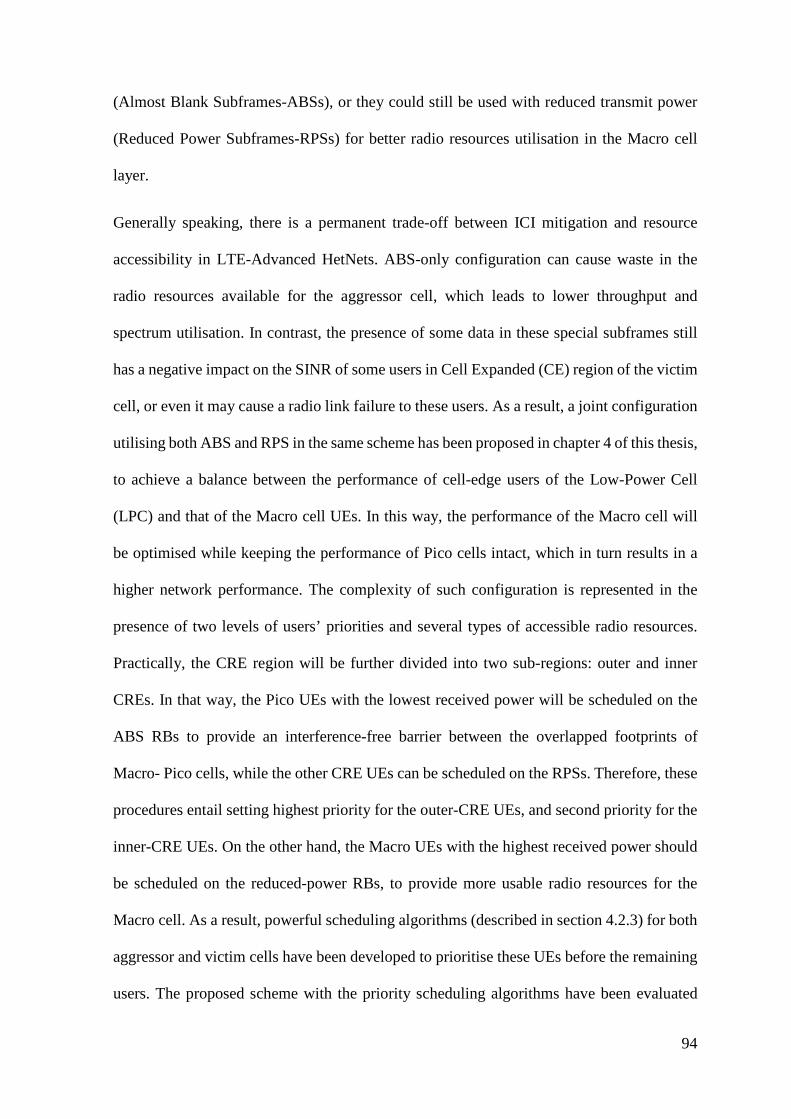
94
(Almost Blank Subframes-ABSs), or they could still be used with reduced transmit power
(Reduced Power Subframes-RPSs) for better radio resources utilisation in the Macro cell
layer.
Generally speaking, there is a permanent trade-off between ICI mitigation and resource
accessibility in LTE-Advanced HetNets. ABS-only configuration can cause waste in the
radio resources available for the aggressor cell, which leads to lower throughput and
spectrum utilisation. In contrast, the presence of some data in these special subframes still
has a negative impact on the SINR of some users in Cell Expanded (CE) region of the victim
cell, or even it may cause a radio link failure to these users. As a result, a joint configuration
utilising both ABS and RPS in the same scheme has been proposed in chapter 4 of this thesis,
to achieve a balance between the performance of cell-edge users of the Low-Power Cell
(LPC) and that of the Macro cell UEs. In this way, the performance of the Macro cell will
be optimised while keeping the performance of Pico cells intact, which in turn results in a
higher network performance. The complexity of such configuration is represented in the
presence of two levels of users’ priorities and several types of accessible radio resources.
Practically, the CRE region will be further divided into two sub-regions: outer and inner
CREs. In that way, the Pico UEs with the lowest received power will be scheduled on the
ABS RBs to provide an interference-free barrier between the overlapped footprints of
Macro- Pico cells, while the other CRE UEs can be scheduled on the RPSs. Therefore, these
procedures entail setting highest priority for the outer-CRE UEs, and second priority for the
inner-CRE UEs. On the other hand, the Macro UEs with the highest received power should
be scheduled on the reduced-power RBs, to provide more usable radio resources for the
Macro cell. As a result, powerful scheduling algorithms (described in section 4.2.3) for both
aggressor and victim cells have been developed to prioritise these UEs before the remaining
users. The proposed scheme with the priority scheduling algorithms have been evaluated
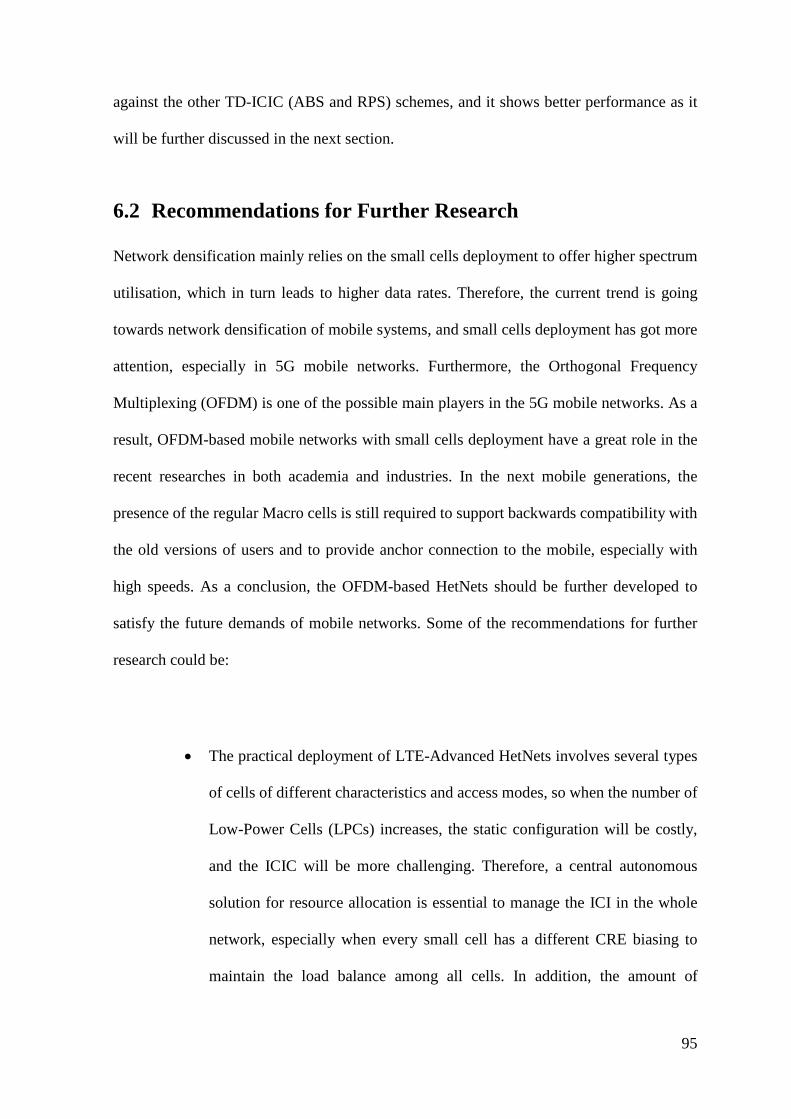
95
against the other TD-ICIC (ABS and RPS) schemes, and it shows better performance as it
will be further discussed in the next section.
6.2 Recommendations for Further Research
Network densification mainly relies on the small cells deployment to offer higher spectrum
utilisation, which in turn leads to higher data rates. Therefore, the current trend is going
towards network densification of mobile systems, and small cells deployment has got more
attention, especially in 5G mobile networks. Furthermore, the Orthogonal Frequency
Multiplexing (OFDM) is one of the possible main players in the 5G mobile networks. As a
result, OFDM-based mobile networks with small cells deployment have a great role in the
recent researches in both academia and industries. In the next mobile generations, the
presence of the regular Macro cells is still required to support backwards compatibility with
the old versions of users and to provide anchor connection to the mobile, especially with
high speeds. As a conclusion, the OFDM-based HetNets should be further developed to
satisfy the future demands of mobile networks. Some of the recommendations for further
research could be:
• The practical deployment of LTE-Advanced HetNets involves several types
of cells of different characteristics and access modes, so when the number of
Low-Power Cells (LPCs) increases, the static configuration will be costly,
and the ICIC will be more challenging. Therefore, a central autonomous
solution for resource allocation is essential to manage the ICI in the whole
network, especially when every small cell has a different CRE biasing to
maintain the load balance among all cells. In addition, the amount of

96
information exchanged for coordination should be taken into further
considerations.
• Due to the importance of CRE concept of mitigating the UL interference and
achieving more load balance in the HetNets, the relationship between CRE
values and the load balance in the network should be further investigated,
especially when the increment in this value results in more traffic included in
the cells which have a significant impact on cell capacity. Furthermore, the
impact of limited backhaul of the Pico cell in higher CRE values should be
taken into account, which has a negative effect on the Pico cell functionality
in most mobile networks.
• The increasing demands for mobile data and the expanding use of smart
devices entail services of various traffic requirements and different priorities
which should be taken into considerations in the future designs of ICIC
schemes.

97
6.3 Reflection on the PhD Research
During my journey through the four-year PhD project, many skills have been learned and
several challenges have been tackled. Choosing an up-to-date research problem and
investigating the potential benefits of the proposed solution for the future research are tasks
that should be carefully considered and analysed, as hundreds of research studies are being
carried out in similar fields and so new and different systems are emerging every year. This
choice was further discussed with the supervisors to get their advice based on the wide
academic experience they have. In addition, time management was a vital issue which can
have a significant impact on the research progress.
Several skills are necessary for any researcher in this field, namely those related to
programming skills and presentation skills, which have been learned by the aid of my
supervisor, Salford University, and the other researchers. Many challenges have also been
faced, which had a negative impact on the research project. The most important challenge
for this research was finding the appropriate simulation tools which could fully support the
proposed solution and the possibility of adapting this tool to simulate different scenarios.
Most commercial simulation tools have strict modification capabilities and they have high
license costs. On the contrary, the open-source tools are free and easy to modify but there is
less support available when facing some difficulties in implementation. I have struggled to
find the suitable simulation tools for my research project and much time was lost on this
matter.
One of the most challenging issues in this research is the intensive research of this field,
which makes the novelty of the proposal more challenging because hundreds of publications
were showing detailed investigation and saturated ideas in inter-cell interference
coordination of LTE-A mobile systems.
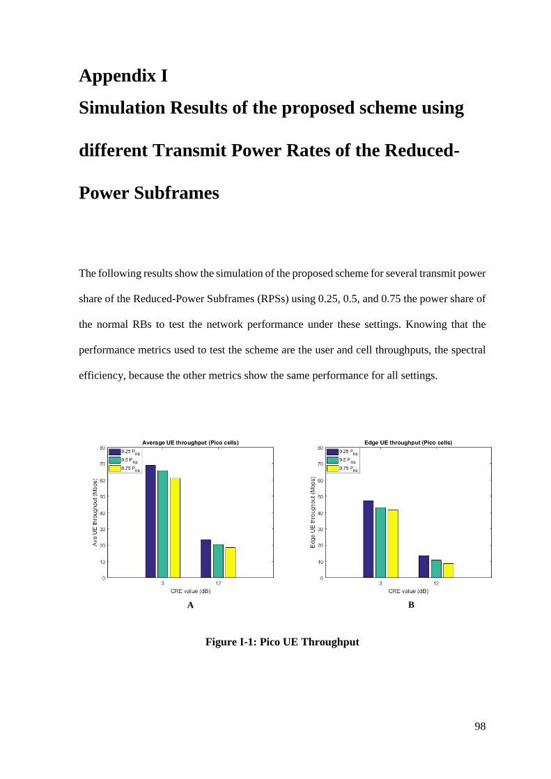
98
Appendix I
Simulation Results of the proposed scheme using
different Transmit Power Rates of the Reduced-
Power Subframes
The following results show the simulation of the proposed scheme for several transmit power
share of the Reduced-Power Subframes (RPSs) using 0.25, 0.5, and 0.75 the power share of
the normal RBs to test the network performance under these settings. Knowing that the
performance metrics used to test the scheme are the user and cell throughputs, the spectral
efficiency, because the other metrics show the same performance for all settings.
BA
Figure I-1: Pico UE Throughput
99
BA
Figure I-2: Macro UE Throughput
BA
Figure I-3: Total UE Throughput
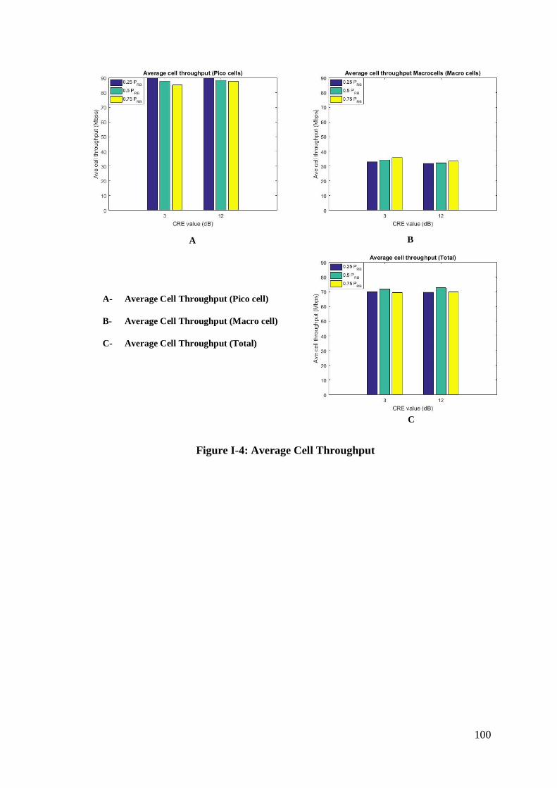
100
A B
C
A- Average Cell Throughput (Pico cell)
B- Average Cell Throughput (Macro cell)
C- Average Cell Throughput (Total)
Figure I-4: Average Cell Throughput
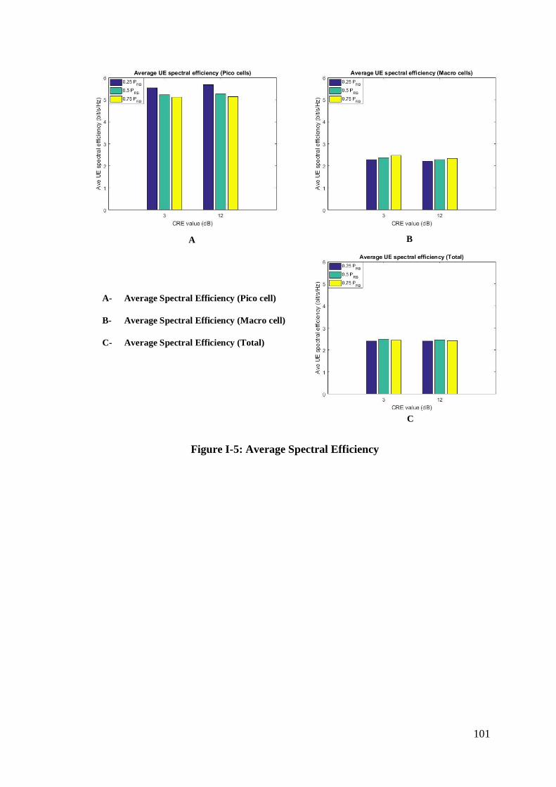
101
A B
C
A- Average Spectral Efficiency (Pico cell)
B- Average Spectral Efficiency (Macro cell)
C- Average Spectral Efficiency (Total)
Figure I-5: Average Spectral Efficiency
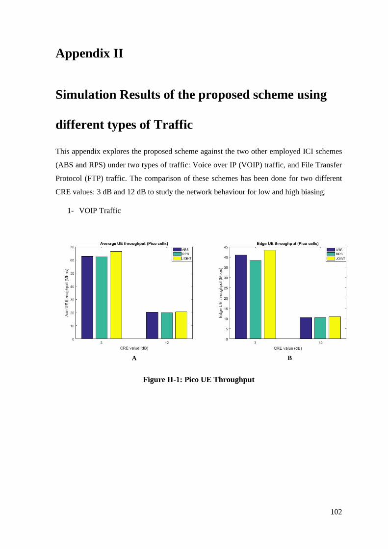
102
Appendix II
Simulation Results of the proposed scheme using
different types of Traffic
This appendix explores the proposed scheme against the two other employed ICI schemes
(ABS and RPS) under two types of traffic: Voice over IP (VOIP) traffic, and File Transfer
Protocol (FTP) traffic. The comparison of these schemes has been done for two different
CRE values: 3 dB and 12 dB to study the network behaviour for low and high biasing.
1- VOIP Traffic
BA
Figure II-1: Pico UE Throughput
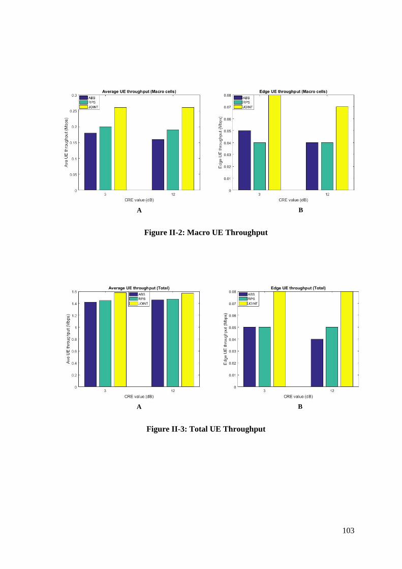
103
BA
Figure II-2: Macro UE Throughput
BA
Figure II-3: Total UE Throughput
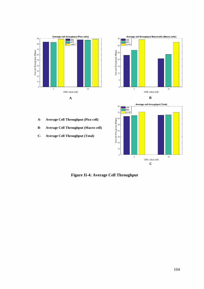
104
A B
C
A- Average Cell Throughput (Pico cell)
B- Average Cell Throughput (Macro cell)
C- Average Cell Throughput (Total)
Figure II-4: Average Cell Throughput
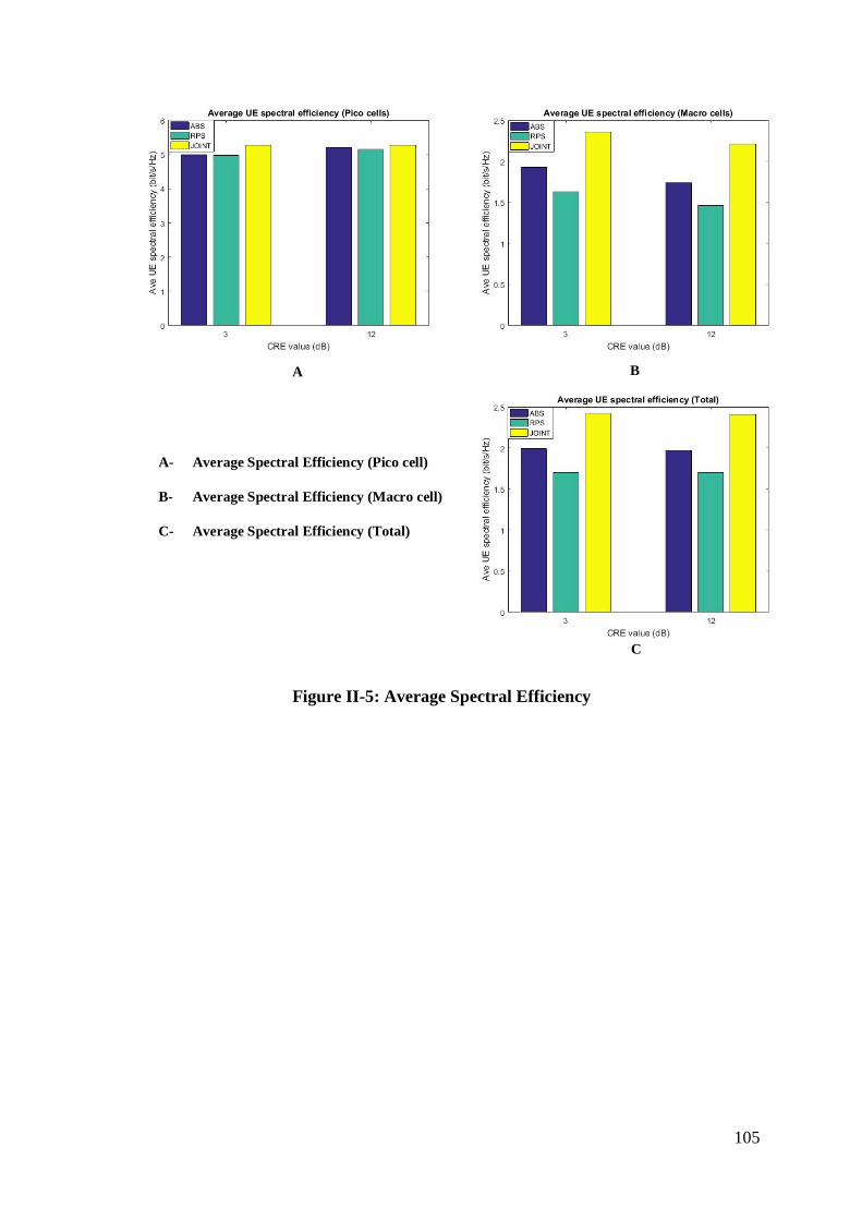
105
A B
C
A- Average Spectral Efficiency (Pico cell)
B- Average Spectral Efficiency (Macro cell)
C- Average Spectral Efficiency (Total)
Figure II-5: Average Spectral Efficiency
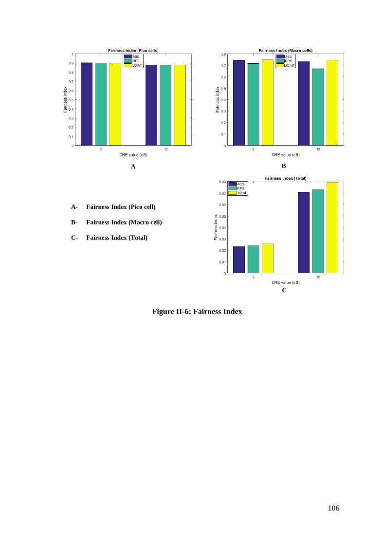
106
A B
C
A- Fairness Index (Pico cell)
B- Fairness Index (Macro cell)
C- Fairness Index (Total)
Figure II-6: Fairness Index
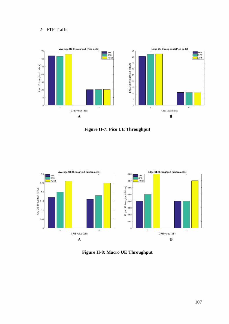
107
2- FTP Traffic
BA
Figure II-7: Pico UE Throughput
BA
Figure II-8: Macro UE Throughput
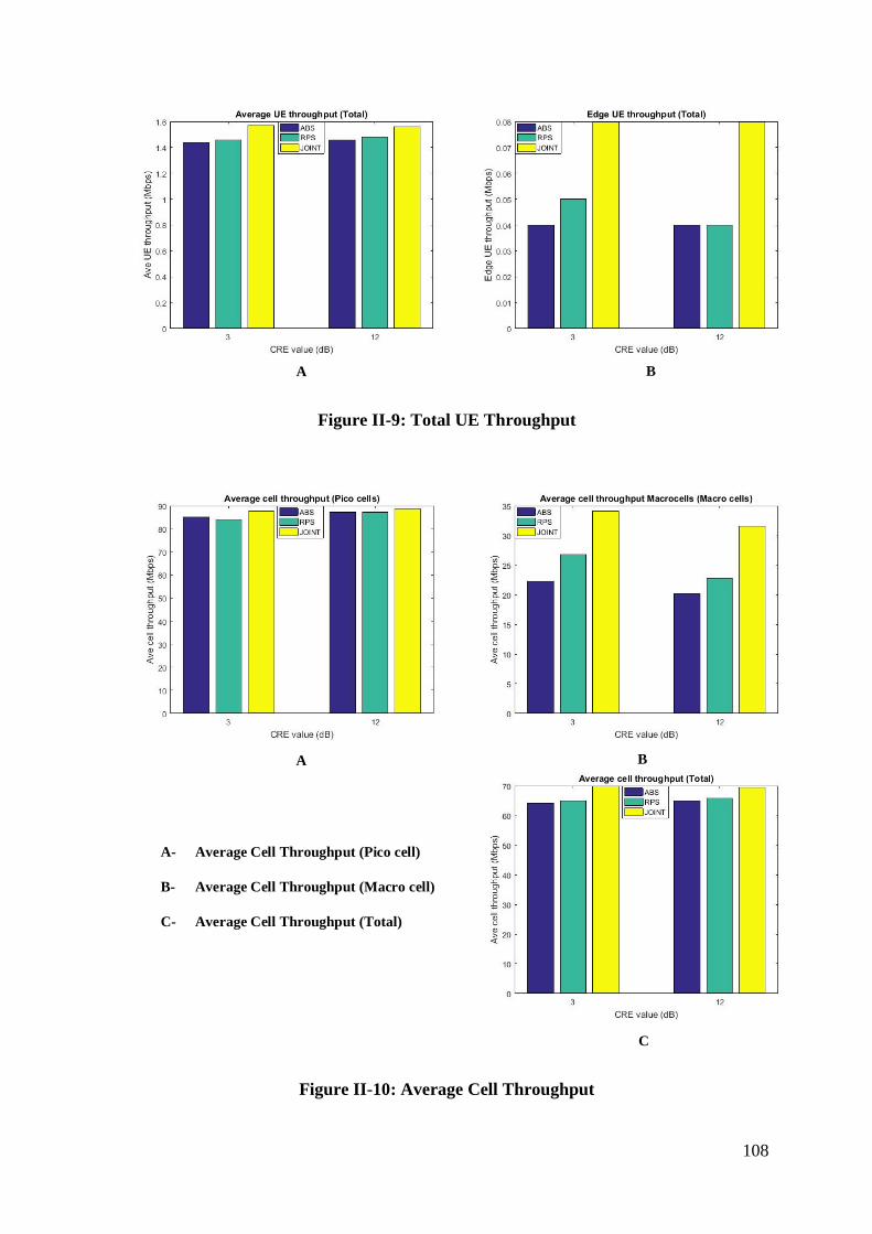
108
BA
Figure II-9: Total UE Throughput
A B
C
A- Average Cell Throughput (Pico cell)
B- Average Cell Throughput (Macro cell)
C- Average Cell Throughput (Total)
Figure II-10: Average Cell Throughput
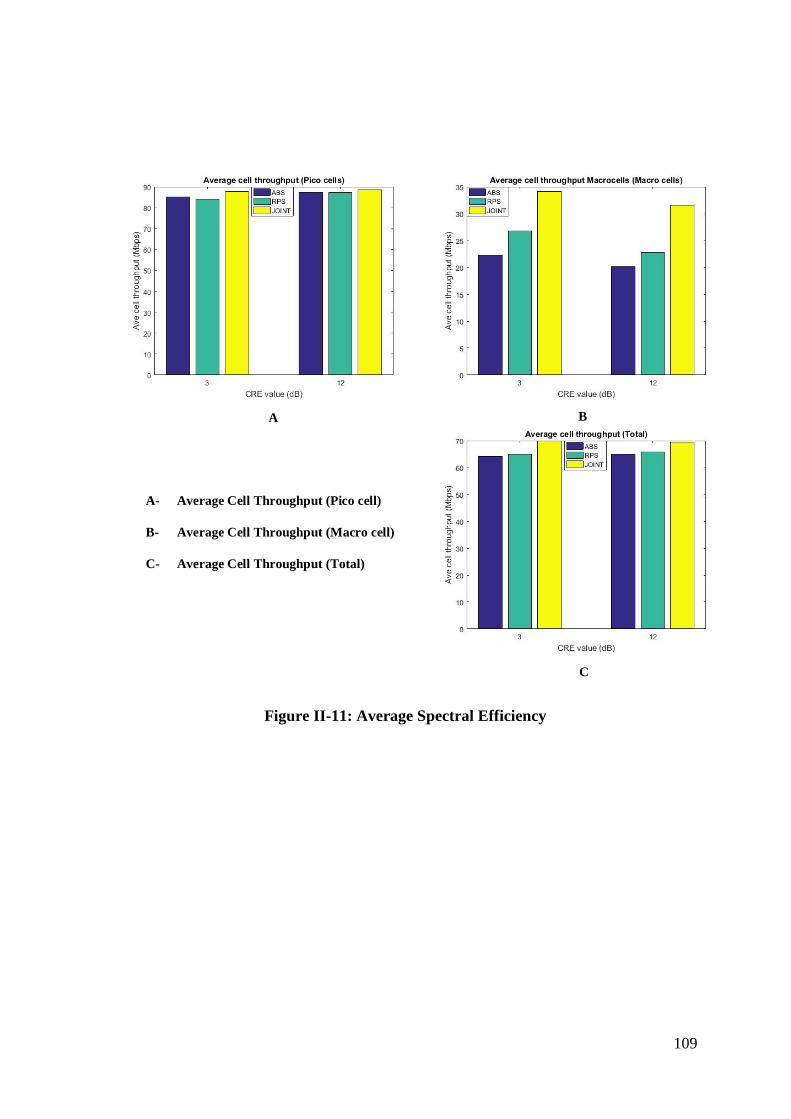
109
A B
C
A- Average Cell Throughput (Pico cell)
B- Average Cell Throughput (Macro cell)
C- Average Cell Throughput (Total)
Figure II-11: Average Spectral Efficiency
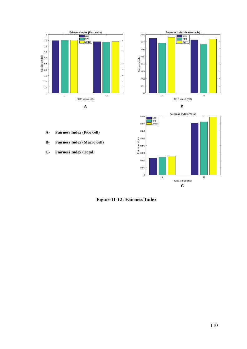
110
A B
C
A- Fairness Index (Pico cell)
B- Fairness Index (Macro cell)
C- Fairness Index (Total)
Figure II-12: Fairness Index
111
References [1] Cisco, “Global Mobile Data Traffic Forecast Update, 2016-2021 (White Paper),”
2017.
[2] D. López-Pérez and X. Chu, “Inter-cell interference coordination for expanded region
picocells in heterogeneous networks,” Proc. - Int. Conf. Comput. Commun. Networks,
ICCCN, 2011.
[3] D. López-Pérez, X. Chu, and I. Güvenç, “On the expanded region of picocells in
heterogeneous networks,” IEEE J. Sel. Top. Signal Process., vol. 6, no. 3, pp. 281–
294, 2012.
[4] 3GPP, “GSM additional features, GPRS,” no. Release 97. 3rd Generation Partnership
Project, 1996.
[5] B. Furht and S. A. Ahson, Long Term Evolution: 3GPP LTE Radio and Cellular
Technology. Taylor and Francis group, 2009.
[6] S. Sesia, I. Toufik, and M. Baker, LTE- The UMTS Long Term Evolution: From
Theory to Practice, 2nd ed. John Wiley & Sons Ltd, 2011.
[7] NGMN Alliance, “Next Generation Mobile Networks beyond HSPA & EvDo,” White
Pap. Next Gener. Mob. Networks Ltd, 2006.
[8] S. Sesia, I. Toufik, and M. Baker, LTE The UMTS Long Term Evolution: From Theory
to Practice, 2nd ed. JohnWiley & Sons Ltd, 2011.
[9] R. W. Chang, “Synthesis of Band-Limited Orthogonal Signals for Multichannel Data
Transmission,” Bell Syst. Tech. J., vol. 45, pp. 1775–1796, 1966.
[10] H. Burchardt, “Interference Management in Wireless Cellular Networks,” 2013.
[11] A. Ghosh, J. Zhang, J. G. Andrews, and R. Muhamad, Fundamentals of LTE, 1st
Editio. Prentice Hall; 1 edition (September 20, 2010), 2011.
[12] A. Ghosh and R. Ratasuk, Essentials of LTE and LTE-A. Cambridge University Press
112
(4 Aug. 2011), 2011.
[13] T. Bhandare, LTE and WiMAX Comparison, no. December. Santa Clara University,
2008.
[14] M. Rumney, LTE and the Evolution to 4G Wireless Design and Measurement
Challanges, 2nd ed., vol. 53, no. 9. John Wiley & Sons, Ltd, 2013.
[15] J. Acharya, L. Gao, and S. Gaur, Heterogeneous Networks in LTE-Advanced, 1st ed.
John Wiley & Sons Ltd, 2014.
[16] 3GPP TR 36.932, “Scenarios and requirements for small cell enhancements for E-
UTRA and E-UTRAN (Release 14).” 3rd Generation Partnership Project-TSG-RAN,
2017.
[17] 3GPP TS 36.420, “Evolved Universal Terrestrial Radio Access Network (E-
UTRAN); X2 General Aspects and Principles,” no. Release 13. 3rd Generation
Partnership Project TSG-RAN, 2015.
[18] F. Khan, LTE for 4G Mobile Broadband Air Interface Technologies and Performance,
1st ed. CAMBRIDGE UNIVERSITY PRESS, 2009.
[19] 3GPP TR 36.304, “User Equipment (UE) procedures in idle mode (release 14).” 3rd
Generation Partnership Project-TSG-RAN, 2017.
[20] 3GPP TS 36.133, “Requirements for support of radio resource management (Release
14).” 3rd Generation Partnership Project-TSG-RAN, 2017.
[21] E. Hossain, Heterogeneous Wireless Access Networks Architectures and Protocols.
Springer Science+Business Media, LLC, 2008.
[22] 3GPP TS 36.211, “Physical channels and modulation (Release 14).” 3rd Generation
Partnership Project-TSG-RAN, 2017.
[23] C. Johnson, Long Term Evolution in Bullets, 2nd ed. Chris Johnson,
Northampton,England, 2012.
113
[24] 3GPP TR 36.913, “Requirements for further advancements for Evolved Universal
Terrestrial Radio Access (E-UTRA) (LTE-Advanced) (Release 14).” 3rd Generation
Partnership Project-TSG-RAN, p. 15, 2017.
[25] D. López-Pérez, I. Güvenç, G. De La Roche, M. Kountouris, T. Q. S. Quek, and J.
Zhang, “Enhanced intercell interference coordination challenges in heterogeneous
networks,” IEEE Wirel. Commun., vol. 18, no. 3, pp. 22–30, 2011.
[26] S. Brueck, “Heterogeneous networks in LTE-Advanced,” Proc. Int. Symp. Wirel.
Commun. Syst., pp. 171–175, 2011.
[27] 3GPP TR 36.842, “Study on Small Cell enhancements for E-UTRA and E-UTRAN.”
3rd Generation Partnership Project-TSG-RAN, 2013.
[28] H. Otsuka, Y. Ichimura, Y. Sakamoto, and K. Kikuchi, “Considerations of Small Cell
Strategy in Mobile Communication Systems,” pp. 1259–1262, 2013.
[29] Ericsson, “LTE Release 12,” White Pap., no. January, 2013.
[30] Y. W. Damnjanovic, Aleksandar ; Juan Montojo, “A Survey on 3GPP Heterogeneous
Networks,” IEEE Wirel. Commun., no. June, pp. 10–21, 2011.
[31] G. Boudreau, J. Panicker, N. Guo, R. Chang, N. Wang, and S. Vrzic, “Interference
coordination and cancellation for 4G networks,” IEEE Commun. Mag., vol. 47, no. 4,
pp. 74–81, 2009.
[32] S. Hamouda, “A New Spectrum Sharing Trade in Heterogeneous Networks,” 2013.
[33] Y. Wang and K. I. Pedersen, “Performance Analysis of Enhanced Inter-Cell
Interference Coordination in LTE-Advanced Heterogeneous Networks,” 2012 IEEE
75th Veh. Technol. Conf. (VTC Spring), pp. 1–5, 2012.
[34] 3GPP RP-121415, “New Carrier Type for LTE.” 3rd Generation Partnership Project-
TSG-RAN#57, 2012.
[35] E. Seidel and C. T. Officer, “LTE-A HetNets using Carrier Aggregation,” 2013.
114
[36] S. Moon, S. Malik, B. Kim, H. Choi, S. Park, C. Kim, and I. Hwang, “Cell range
expansion and time partitioning for enhanced inter-cell interference coordination in
heterogeneous network,” Proc. Annu. Hawaii Int. Conf. Syst. Sci., pp. 5109–5113,
2014.
[37] 3GPP RP-130391, “LTE Carrier Aggregation between TDD and FDD.” 3rd
Generation Partnership Project-TSG-RAN#59, Vienna, Austria, 2013.
[38] 3GPP R1-084026, “LTE-Advanced Evaluation methodology.” 3rd Generation
Partnership Project-TSG-RAN WG1 #54bis, p. 27, 2008.
[39] M. Shirakabe, A. Morimoto, and N. Miki, “Performance evaluation of inter-cell
interference coordination and cell range expansion in heterogeneous networks for
LTE-Advanced downlink,” Proc. Int. Symp. Wirel. Commun. Syst., pp. 844–848,
2011.
[40] M. Jeong, F. Watanabe, and P. Alto, “Range Expansion and Inter-Cell Interference
Coordination ( ICIC ) for Picocell Networks,” no. Icic, 2011.
[41] C. Hoymann, D. Larsson, H. Koorapaty, and J. F. Cheng, “A lean carrier for LTE,”
IEEE Commun. Mag., vol. 51, no. 2, pp. 74–80, 2013.
[42] X. Lin, J. G. Andrews, R. Ratasuk, B. Mondal, and A. Ghosh, “Carrier aggregation in
heterogeneous cellular networks,” IEEE Int. Conf. Commun., pp. 5199–5203, 2013.
[43] B. A. Salihu, Z. Suleiman, and M. U. M. Bakura, “Advances in inter-cell interference
coordination for realization of robust Heterogeneous Networks in lte-a systems,” Int.
J. Eng. Sci. Invent., vol. 2, no. 2, pp. 40–48, 2013.
[44] 3GPP TS 22.220, “Service requirements for Home Node B (HNB) and Home eNode
B (HeNB) (Release 14).” 3rd Generation Partnership Project-TSG Services and
System Aspects, p. 25, 2017.
[45] A. Valcarce, D. López-Pérez, G. De La Roche, and J. Zhang, “Limited access to
115
OFDMA femtocells,” IEEE Int. Symp. Pers. Indoor Mob. Radio Commun. PIMRC,
pp. 1–5, 2009.
[46] D. Choi, P. Monajemi, S. Kang, and J. Villasenor, “Dealing with loud neighbors: the
benefits and tradeoffs of adaptive femtocell access,” GLOBECOM - IEEE Glob.
Telecommun. Conf., pp. 2817–2821, 2008.
[47] Y. Saito, N. Miki, T. Abe, and S. Nagata, “Investigation on Cell Selection Methods
Associated with Inter-cell Interference Coordination in Heterogeneous Network for
LTE-Advanced Downlink,” pp. 139–144, 2011.
[48] a Ghosh, N. Mangalvedhe, R. Ratasuk, B. Mondal, M. Cudak, E. Visotsky, T. a
Thomas, J. G. Andrews, P. Xia, H.-S. Jo, H. S. Dhillon, and T. D. Novlan,
“Heterogeneous cellular networks: From theory to practice,” Commun. Mag. IEEE,
vol. 50, no. 6, pp. 54–64, 2012.
[49] S. Parkvall, A. Furuskar, and E. Dahlman, “Evolution of LTE toward IMT-
Advanced,” no. February, pp. 84–91, 2011.
[50] E. Dahlman, S. Parkvall, J. Skold, and P. Beming, 3G Evolution HSPA and LTE for
Mobile Broadband. Elsevier Ltd, 2008.
[51] 3GPP TR 36.839, “Mobility enhancements in heterogeneous networks (Release 11),”
vol. 0, no. Release 11. 3rd Generation Partnership Project-TSG-RAN, pp. 1–53, 2012.
[52] M. Anas, F. D. Calabrese, P. E. Östling, K. I. Pedersen, and P. E. Mogensen,
“Performance analysis of handover measurements and layer 3 filtering for UTRAN
LTE,” IEEE Int. Symp. Pers. Indoor Mob. Radio Commun. PIMRC, 2007.
[53] H. Jiang, H. Wang, W. Zhu, Z. Li, Z. Pan, N. Liu, X. You, and L. Yang, “Carrier
aggregation based interference coordination for LTE-A macro-pico HetNet,” IEEE
Veh. Technol. Conf., 2013.
[54] 3GPP TS 36.300, “Overall description (Release 14),” vol. 0. 3rd Generation
116
Partnership Project-TSG-RAN, p. 328, 2017.
[55] A. B. Carleial, “A Case Where Interference Does Not Reduce Capacity,” IEEE Trans.
Inf. Theory, vol. 21, no. 5, pp. 569–570, 1975.
[56] D. López-Pérez, “Practical Models and Optimisation Methods for Inter-Cell
Interference Coordination in Self-organising Cellular Networks,” Bedfordshire, 2013.
[57] A. Goldsmith, Wireless communications. 2005.
[58] G. Calhoun, Digital Cellular Radio, 1st ed. Artech House, Inc., 1988.
[59] V.H.MAC Donald, “The Cellular Concept,” Bell Syst. Tech. J., vol. 58, no. 1, pp. 1–
27, 1978.
[60] S. E. Elayoubi, O. Ben Haddada, and B. Fourestié, “Performance evaluation of
frequency planning schemes in OFDMA-based networks,” IEEE Trans. Wirel.
Commun., vol. 7, no. 5, pp. 1623–1633, 2008.
[61] A. S. A. E. M. Y. TAKAKI, C. OHTA, H. TAMAKI, Y. TANAKA, T.
YAMAMOTO, and O. Yoji, “Fair partitioning of the downlink resources of an
OFDMA-based multiuser multi-tier cellular network using fractional frequency
reuse,” EICE Trans. Commun., 2012.
[62] T. D. Novlan, R. K. Ganti, A. Ghosh, and J. G. Andrews, “Analytical Evaluation of
Fractional Frequency Reuse for OFDMA Cellular Networks,” IEEE Trans. Wirel.
Commun., vol. 10, no. 12, pp. 4294–4305, 2011.
[63] A. Daeinabi, “Intercell Interference Mitigation in Long Term Evolution ( LTE ) and
LTE-Advanced,” University of Technology, Sydney, 2015.
[64] 3GPP TR36.819, “Coordinated multi-point operation for LTE physical layer aspects
(Release 11).” 3rd Generation Partnership Project-TSG Services and System Aspects,
p. 70, 2013.
[65] Q. Cui, S. Yang, Y. Xu, X. Tao, and B. Liu, “An effective inter-cell interference
117
coordination scheme for downlink CoMP in LTE-A systems,” IEEE Veh. Technol.
Conf., no. 61027003, 2011.
[66] S. Sun, Q. Gao, Y. Peng, and Y. Wang, “Interference Management through CoMP in
3gpp LTE-Advanced Networks,” no. February, pp. 59–66, 2013.
[67] T. Akbudak and A. Czylwik, “CoMP in Heterogeneous Networks : Low-Complexity
Joint Cooperative Resource Allocation with SDMA.”
[68] 3rd Generation Partnership Project, “Technical Specification Group Radio Access
Network;Coordinated multi-point operation for LTE with non-ideal backhaul
(Release 12).”
[69] I. F. Akyildiz, D. M. Gutierrez-Estevez, R. Balakrishnan, and E. Chavarria-Reyes,
“LTE-Advanced and the evolution to Beyond 4G (B4G) systems,” Phys. Commun.,
vol. 10, pp. 31–60, Nov. 2013.
[70] 3GPP R3-111419, “A plan for LTE Rel-11 Carrier Based Interference Management.”
3rd Generation Partnership Project-TSG-RAN WG3 #72, Barcelona, Spain, 2011.
[71] L. Lindbom, R. Love, S. Krishnamurthy, C. Yao, and N. Miki, “Enhanced inter-cell
interference coordination for heterogeneous networks in LTE-advanced: A survey,”
2011.
[72] Q. Ye, B. Rong, Y. Chen, C. Caramanis, and J. G. Andrews, “Towards an optimal
user association in heterogeneous cellular networks,” GLOBECOM - IEEE Glob.
Telecommun. Conf., pp. 4143–4147, 2012.
[73] K. Okino, T. Nakayama, C. Yamazaki, H. Sato, and Y. Kusano, “Pico cell range
expansion with interference mitigation toward LTE-advanced heterogeneous
networks,” IEEE Int. Conf. Commun., pp. 3–7, 2011.
[74] I. Guvenc, “Capacity and fairness analysis of heterogeneous networks with range
expansion and interference coordination,” IEEE Commun. Lett., vol. 15, no. 10, pp.
118
1084–1087, 2011.
[75] 3GPP R1-111466, “Full Buffer Evaluation Results for CoMP Scenario 3 and 4.” 3rd
Generation Partnership Project-TSG-RAN WG1 #65, Barcelona, Spain, 2011.
[76] J. Oh and Y. Han, “Cell selection for range expansion with almost blank subframe in
heterogeneous networks,” IEEE Int. Symp. Pers. Indoor Mob. Radio Commun.
PIMRC, pp. 653–657, 2012.
[77] a. Daeinabi, K. Sandrasegaran, and X. Zhu, “Performance evaluation of cell selection
techniques for picocells in LTE-advanced networks,” 2013 10th Int. Conf. Electr.
Eng. Comput. Telecommun. Inf. Technol., pp. 1–6, May 2013.
[78] Dario Sabella, Damiano Rapone, Maurizio Fodrini, and Magnus Olsson, “Energy
management in mobile networks towards 5G.” Springer, Cham, 2016.
[79] K. I. Pedersen, Y. Wang, S. Strzyz, and F. Frederiksen, “Enhanced inter-cell
interference coordination in co-channel multi-layer LTE-advanced networks,” IEEE
Wirel. Commun., vol. 20, no. 3, pp. 120–127, 2013.
[80] R. Mendrzik, R. A. J. Castillo, G. Bauch, and E. Seidel, “Interference coordination-
based downlink scheduling for heterogeneous LTE-A networks,” IEEE Wirel.
Commun. Netw. Conf. WCNC, vol. 2016–Septe, no. Wcnc, pp. 1–6, 2016.
[81] M. Cierny, H. Wang, R. Wichman, and Z. Ding, “On number of almost blank
subframes in heterogenous cellular networks Number of ABSFs,” vol. 12, no. 10, pp.
1–5, 2013.
[82] D. Lopez-Perez and H. Claussen, “Duty cycles and load balancing in HetNets with
eICIC almost blank subframes,” IEEE Int. Symp. Pers. Indoor Mob. Radio Commun.
PIMRC, no. Icic, pp. 173–178, 2013.
[83] K. I. Pedersen, B. Soret, S. Barcos Sanchez, G. Pocovi, and H. Wang, “Dynamic
Enhanced Intercell Interference Coordination for Realistic Networks,” IEEE Trans.
119
Veh. Technol., vol. 65, no. 7, pp. 5551–5562, 2016.
[84] M. Al-Rawi, J. Huschke, and M. Sedra, “Dynamic protected-subframe density
configuration in LTE heterogeneous networks,” 2012 21st Int. Conf. Comput.
Commun. Networks, ICCCN 2012 - Proc., pp. 1–6, 2012.
[85] S. N. S. Kshatriya, S. Kaimalettu, S. R. Yerrapareddy, K. Milleth, and N. Akhtar, “On
interference management based on subframe blanking in Heterogeneous LTE
networks,” 2013 Fifth Int. Conf. Commun. Syst. Networks, pp. 1–7, Jan. 2013.
[86] M. Amara and A. Feki, “Optimized ABS in LTE-advanced heterogeneous networks
with adaptive macro cell transmission,” 2015 IEEE Globecom Work. GC Wkshps
2015 - Proc., 2015.
[87] J. Miernik and P. James, “Algorithms for Enhanced Inter-Cell interference
Coordination (elCIC) in LTE HetNets,” Trans. Netw., vol. 22, no. 1, pp. 137–150,
2014.
[88] A. Daeinabi, K. Sandrasegaran, and S. Barua, “A dynamic almost blank subframe
scheme for video streaming traffic model in heterogeneous networks,” ECTI-CON
2015 - 2015 12th Int. Conf. Electr. Eng. Comput. Telecommun. Inf. Technol., 2015.
[89] S. Singh and J. G. Andrews, “Joint resource partitioning and offloading in
heterogeneous cellular networks,” IEEE Trans. Wirel. Commun., vol. 13, no. 2, pp.
888–901, 2014.
[90] M. Eguizábal and Á. Hernández, “Interference management and cell range expansion
analysis for LTE picocell deployments,” IEEE Int. Symp. Pers. Indoor Mob. Radio
Commun. PIMRC, pp. 1592–1597, 2013.
[91] 3GPP R1-114298, “Further system performance evaluations on FeICIC.” 3rd
Generation Partnership Project TSG-RAN WG1 #67, San Francisco, US, 2011.
[92] N. Naganuma, S. Nakazawa, S. Suyama, Y. Okumura, and H. Otsuka, “Adaptive
120
control CRE technique for eICIC in HetNet,” Int. Conf. Ubiquitous Futur. Networks,
ICUFN, vol. 2016–Augus, no. 2, pp. 4–6, 2016.
[93] Y. Sun, T. Deng, Y. Fang, M. Wang, and Y. Wu, “A method for pico-specific upper
bound CRE bias setting in HetNet,” 2013 IEEE Wirel. Commun. Netw. Conf. Work.,
pp. 80–84, Apr. 2013.
[94] C. Y. Lee, “Cell planning with capacity expansion in mobile communications: a tabu
search approach,” IEEE Trans. Veh. Technol., vol. 49, no. 5, pp. 1678–1691, 2000.
[95] E. Amaldi, a. Capone, F. Malucelli, and F. Signori, “Optimization models and
algorithms for downlink UMTS radio planning,” 2003 IEEE Wirel. Commun.
Networking, 2003. WCNC 2003., vol. 2, no. C, pp. 827–831, 2003.
[96] K. Majewski and M. Koonert, “Conservative cell load approximation for radio
networks with shannon channels and its application to LTE network planning,” 6th
Adv. Int. Conf. Telecommun. AICT 2010, pp. 219–225, 2010.
[97] S. Kaneko, T. Matsunaka, and Y. Kishi, “A cell-planning model for HetNet with CRE
and TDM-ICIC in LTE-advanced,” IEEE Veh. Technol. Conf., 2012.
[98] B. Soret, H. Wang, K. Pedersen, and C. Rosa, “Multicell cooperation for LTE-
advanced heterogeneous network scenarios,” IEEE Wirel. Commun., vol. 20, no. 1,
pp. 27–34, 2013.
[99] A. Merwaday, S. Mukherjee, and I. G??ven??, “HetNet capacity with reduced power
subframes,” IEEE Wirel. Commun. Netw. Conf. WCNC, vol. 2, pp. 1380–1385, 2014.
[100] 3GPP R1-120023, “Analysis of feasibility and standard impact of reduced power
ABS.” 3rd Generation Partnership Project TSG-RAN WG1 #68, Dresden, Germany,
p. 3, 2012.
[101] 3GPP R1-113635, “Performance evaluation of FeICIC with zero and reduced power
ABS.” 3rd Generation Partnership Project TSG-RAN WG1 #67, San Francisco, USA,
121
2011.
[102] 3GPP R1-114299, “On air interface changes for FeICIC.” 3rd Generation Partnership
Project TSG-RAN WG1 #67, San Francisco, US, p. 2, 2011.
[103] 3GPP R1-121489, “Discussion on the features and signalling support for non-zero
transmit power ABS.” 3rd Genereation Partnership Project-TSG-RAN1 #68bis, Jeju,
Korea, 2012.
[104] J. Z. Haonan Hu, Jialai Weng, “Coverage Performance Analysis of FeICIC Low-
Power Subframes,” vol. 15, no. 8, pp. 5603–5614, 2016.
[105] J. Ben Abderrazak and H. Besbes, “Joint User Association and Power Minimization
for a Two-Tier HetNet with Interference Coordination and QoS Guarantees,” no. 1,
pp. 1261–1267, 2017.
[106] A. Merwaday and I. Güvenç, “Optimisation of FeICIC for energy efficiency and
spectrum efficiency in LTE-advanced HetNets,” Electron. Lett., vol. 52, no. 11, pp.
982–984, 2016.
[107] A. Virdis, G. Stea, D. Sabella, and M. Caretti, “A distributed power-saving framework
for LTE HetNets exploiting Almost Blank Subframes,” IEEE Trans. Green Commun.
Netw., vol. 1, no. 3, pp. 1–1, 2017.
[108] H. Hu, J. Weng, J. Zhang, J. Zhang, and Y. Wang, “Modelling and analysis of reduced
power subframes in two-tier femto HetNets,” IEEE Veh. Technol. Conf., vol. 2016–
July, no. 0, 2016.
[109] Vienna University of Technology (Institute of Telecommunications), “Vienna
Simulators LTE-A Downlink System Level Simulators Documentation, v1.9 Q2-
2016,” pp. 1–38, 2016.
[110] Markus Rupp and Stefan Schwarz and Martin Taranetz, The Vienna LTE-Advanced
Simulators: Up and Downlink, Link and System Level Simulation, 1st ed. Springer
122
Singapore, 2016.
[111] F. Bernardo, R. Agustí, J. Cordero, and C. Crespo, “Self-optimization of spectrum
assignment and transmission power in OFDMA femtocells,” 6th Adv. Int. Conf.
Telecommun. AICT 2010, pp. 404–409, 2010.
[112] 3GPP R2-110938, “Definition of ABS, Almost Blank Subframe.” 3rd Generation
Partnership Project-TSG-RAN WG2 #73, 2011.
[113] B. Devillers, J. Louveaux, and L. Vandendorpe, “Bit and Power Allocation for
Goodput Optimization in Coded Parallel Subchannels With ARQ,” vol. 56, no. 8, pp.
3652–3661, 2008.
[114] 3GPP TR 36.942, “Evolved Universal Terrestrial Radio Access (E-UTRA); Radio
Frequency (RF) System Scenarios.” 3rd Genereation Partnership Project-TSG-RAN,
2017.
[115] 3GPP TR 36.814, “Further advancements for E-UTRA physical layer aspects.” 3rd
Genereation Partnership Project-TSG-RAN, 2017.
[116] B. Soret and K. I. Pedersen, “Macro transmission power reduction for HetNet co-
channel deployments,” GLOBECOM - IEEE Glob. Telecommun. Conf., pp. 4126–
4130, 2012.
[117] M. Mustaqim, K. Khan, and M. Usman, “LTE-Advanced: Requirements and technical
challenges for 4G cellular network,” J. Emerg. Trends Comput. Inf. Sci., vol. 3, no. 5,
pp. 665–671, 2012.
[118] G. Cong, “Pico Cell Densification Study in LTE Heterogeneous Networks,” 2012.
[119] 3GPP TR 25.816, “UMTS 900 MHz Work Item Technical Report,” vol. 0, no.
Release8. 3rd Generation Partnership Project-TSG-RAN, 2009.
[120] X. Chu, D. Lopez-Perez, Y. Yang, and F. Gunnarsson, Heterogeneous Cellular
Networks: Theory, Simulation and Deployment, First edit. Cambidge University
123
Press, 2013.
[121] E. C. Cherry, “A history of the theory of information,” Proc. IEEE Radio Commun.
Eng., vol. 98, no. 55, pp. 383–393, 1951.
[122] S. Ahmadi, A Practical Systems Approach 3GPP LTE Releases 10 and 11 Radio
Access Technologies LTE-Advanced. 2013.
[123] R. Jain, D. Chiu, and W. Hawe, “A Quantitative Measure Of Fairness And
Discrimination For Resource Allocation In Shared Computer Systems.” ACM
Transaction on Computer Systems, 1984.
Recommended