IMPORTANT SAFETY INSTRUCTIONSREAD AND FOLLOW ALL INSTRUCTIONS
SAVE THESE INSTRUCTIONS
INTELLIVALVE™
2-WAY, 3-WAY VALVE ACTUATOR
INSTALLATION ANDUSER’S GUIDE
AUTOOFF SERVICE
MODE0 2424
68
10 12 1416
182022
L R
SET
CCW/CW
SAVECWCCW

INTELLIVALVE™ Valve Actuator Installation and User’s Guide
Important Warning and Safety Instructions ............................................................................................ iii
Overview ............................................................................................... 4
Installation ............................................................................................ 5-7
Operation ............................................................................................... 8
Mode Button Functions ................................................................. 8 Mode Button ......................................................................... 8 AUTO Mode .......................................................................... 8 OFF Mode ............................................................................ 8Setting Home Position ................................................................... 9SET Mode (Using RED/Yellow Arrow Buttons)............................... 9Service Mode................................................................................. 10Comparision to Standard valve Actuator Toggle Switchch............................................................................. 10Changing Home Position ............................................................... 11Example: Example: IntelliValve Valve Actuator on Return Valve to Split to Pool /Spa for Spillway Effect .......................................................................... 123-Way Valve: Diverter Position vs IntelliValve Actuator LED position .................................................. 132-Way Valve: Diverter Position vs IntelliValve Actuator LED position.............................................. 143-Way Y Valve: Diverter Position vs IntelliValve Actuator LED position.............................................. 15Connecting Power to the IntelliValve Actuator (EasyTouch and IntelliTouch Control Systems) ............................ 17Troubleshooting ............................................................................. 19
P/N 522301 Rev. B 12/2015
ii
CUSTOMER SERVICE / TECHNICAL SUPPORT
TABLE OF CONTENTS
Customer Service (8 A.M. to 7:30 P.M.) (Eastern and Pacific Times)
Phone: (800) 831-7133
Fax: (800) 284-4151
Web site
Visit www.pentairpool.com

INTELLIVALVE™ Valve Actuator Installation and User’s Guide
Before installing this product, read and follow all warning notices and instructions in this Guide. Failure to follow warnings and instructions can result in severe injury, death, or property damage. Call (800) 831-7133 for additional free copies of these instructions. Please refer to www.pentairpool.com for more information related to this products.
Attention Installer: This Installation and User’s Guide (“Guide”) contains important information about the installation, operation and safe use of this underwater pool and spa light. This Guide should be given to the owner and/or operator of this equipment.
Attention User: This manual contains important information that will help you in operating and maintaining this product. Please retain it for future reference.
SERIOUS BODILY INJURY OR DEATH CAN RESULT IF THE INTELLIVALVE™ VALVE ACTUATOR IS NOT INSTALLED AND USED CORRECTLY. INSTALLERS, POOL OPERATORS AND POOL OWNERS MUST READ THESE WARNINGS AND ALL INSTRUCTIONS BEFORE INSTALLATION THE INTELLIVALVE VALVE ACTUATOR.
This device must be installed by a licensed or certified electrician or a qualified pool professional in accordance with the National Electrical Code (NEC), NFPA 70 or the Canadian Electrical Code (CEC), CSA C22.1.
All applicable current local installation codes and ordinances must also be adhered to. Improper installation will create an electrical hazard which could result in death or serious injury to pool users, installers or others due to electrical shock, and may also cause damage to property.
Always disconnect the power at the circuit breaker before installation and servicing.
Most states and local codes regulate the construction, installation, and operation of public pools and spas, and the construction of residential pools and spas. It is important to comply with these codes, many of which directly regulate the installation and use of this product. Consult your local building and health codes for more information.
IMPORTANT NOTICE
READ AND FOLLOW ALL INSTRUCTIONS IN THIS MANUALSAVE THESE INSTRUCTIONS
iii
IMPORTANT WARNING AND SAFETY INSTRUCTIONS

INTELLIVALVE™ Valve Actuator Installation and User’s Guide
IntelliValve Valve Actuator Control Pad
4
IntelliValve™ Valve Actuator Overview
From the control pad the IntelliValve valve actuator provides easy setup and control of your diverter valve for pool and spa combinations, fountains, and water features. IntelliValve valve actuator supports Pentair, Compool®, Ortega® or Jandy® diverter valves and is compatible with all 24 VAC control systems.
Features• 24 Volt 50/60 Hz. 0.75 electronically controlled motorized valve actuator• Easy access operator control pad for quick diverter positioning• LEDs indicate diverter location and travel end point positions• 46 possible set positions (approximately every 3.75 degrees) indicated by
24 diverter position LEDs.• Retrofit for all pool/spa diverter valves• Fits all industry standard compatible diverter valves for pool/spa and pool/
water feature combinations• 20 ft. Power Cable
The IntelliValve Valve Actuator is an electronically controlled motorized valve actuator which rotates the diverter valve to a set position for the desired proportion of water flow for various applications.
AUTOOFF SERVICE
MODE0 2424
68
10 12 1416
182022
L R
SET
CCW/CW
SAVECWCCW
SAVE(Save settings button)
Yellow arrow button (Clockwise diverter rotation)
Operation Instructions
Mode button (Toggles between AUTO, SET, and SERVICE modes.)0-24 Red LEDs
SERVICE mode LED (Yellow)
SET mode LED (Blue)
Red arrow button (Counterclockwise
diverter rotation)
Auto mode LED GreenOFF mode LED Red

INTELLIVALVE™ Valve Actuator Installation and User’s Guide
Installing the IntelliValve™ Valve Actuator
INSTALLATION
To install the IntelliValve valve actuator (2 and 3-way valve assembly example shown):
Valve assembly without actuator:
• Unscrew and remove the diverter valve knob and handle. Remove the four (4) screws from the valve assembly top cover (embossed arrows indicate the screw locations). See Figure 1, 2 and 3.
Valve knob
Valve handle
Remove screw
Remove screw Remove screw
Remove screw
Figure 2. 3-Port Valve
Figure 3. 2-Port Valve
Remove screw
Remove screw Remove screw
Remove screw
Figure 1. Diverter Handle/Knob
The IntelliValve Valve Actuator can be installed on a 2-way, 3-way or 3-way Y valve assembly.
Note: To connect the IntelliValve valve actuator power cable to the automation control system, see page 17 and 18. Note: After installing the IntelliValve actuator, proceed to “Setting Home Position” on page 9.
5

INTELLIVALVE™ Valve Actuator Installation and User’s Guide
Valve assembly with existing actuator:
1. Caution: Switch OFF the main system power at the circuit breakers. 2. Disconnect the valve actuator power cord from the control system. 3. Unscrew and remove the diverter valve knob and handle from the valve
actuator. 4. Remove the four (4) screws from the valve actuator assembly. Remove
the actuator from the valve. See Figure 4.
Remove screw
Remove screw
Remove Screws
Figure 4. Valve Assembly with Actuator
Mount the IntelliValve Valve Actuator onto the Valve:
1. Align the splines of the InitelliValve valve actuator shaft over the shaft of the valve. Note: The keyed square spline notch (as shown below) indicates the position of the diverter. Note: End point at 0 (OFF) is the default position of the IntelliValve valve actuator.
Arrow on actuator indicates end point 0 (OFF)
IntelliValve Actuator Spline Notch (underside view)
Spline notch arrow location
Valve Assembly (top view) with diverter at end point 0 OFF
Remove handle
INLET
OF
F
OU
TL
ET
Note: There is silicone on the actuator assembly and spline. While mounting the IntelliValve, be careful not to get silicone on the bottom of the IntelliValve assembly.
2. If the IntelliValve valve actuator does not align with the mounting holes on the valve cover, rotate the actuator (while still attached to the valve) until the actuator manufacturers holes line up on the valve. Continue to next page.
6

INTELLIVALVE™ Valve Actuator Installation and User’s Guide
Installing the IntelliValve™ Valve Actuator (Continued)3. Mount the IntelliValve valve actuator onto the valve assembly and
secure it with the four 2¼ inch mounting screws provided. See Figure 5 and Figure 6. Note: DO NOT over tighten the mounting screws.
Figure 5. IntelliValve Valve Actuator Mounted on a 3-Port Valve assembly
CAUTION: DO NOT mount the IntelliValve so that the suction or return line of the pump can be blocked. This will cause permanent pump damage.
Figure 6. IntelliValve Valve Actuator Mounted on a 2-Port Valve assembly
Mounting screw (x4)
INLET
OUTLET
SPLINE
IntellliValve Valve Actuator
Mounting screw (x4)
INLET
POOL RETURN
SPA RETURN
SPLINE
IntellliValve Valve Actuator
20 ft. power cable plug (3-pin) Connect to automation
control system circuit board (see page 17)
20 ft. power cable plug (3-pin) Connect to automation
control system circuit board (see page 17)
7

INTELLIVALVE™ Valve Actuator Installation and User’s Guide
IntelliValve™ Valve Actuator
Mode Button: Press the MODE button (press and release) to toggle between AUTO/OFF, SET and SERVICE mode.
• AUTO Mode (Normal Operation)
• OFF Mode - Disable IntelliValve Actuator function
• SET Mode: Set travel end points of valve diverter (see page 9)
• SERVICE Mode (Manual control - Temporary Settings) (see page 10)
AUTO Mode (Green LED): The AUTO LED indicator is lit Green when the IntelliValve valve actuator is in normal operation.
• The actuator will move the diverter via the pool and spa automation control system.
• Only the current diverter position LED is lit while the diverter is in motion.• Reversing Home Position from one end point to the other can only be
done in AUTO MODE (see page 11).
OFF Mode: • (Red LED): OFF mode can only be enabled while in AUTO or SERVICE
mode.• Press and hold SAVE until AUTO LED turns Red. • All other buttons are disabled during OFF mode. • To return to ON, press and hold SAVE again until AUTO LED turns Green.
The following describes the IntelliValve Valve Actuator modes of operation.
8
OPERATION
Mode Button Functions
AUTO/OFF (Red LED)
AUTO Mode OFF Mode
AUTO/OFF (Green LED)
Position 0 (Default diverter
position)
INTELLIVALVE™ Valve Actuator Installation and User’s Guide
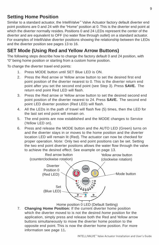
SET Mode (Using Red and Yellow Arrow Buttons)The following steps describe how to change the factory default 0 and 24 position, with “0” being home position or starting from a custom home position.
To change the diverter travel end points:
1. Press MODE button until SET Blue LED is ON.2. Press the Red arrow or Yellow arrow button to set the desired first end
point position of the diverter nearest to 0. This is the diverter return end point after you set the second end point (see Step 3). Press SAVE. The return end point Red LED will flash.
3. Press the Red arrow or Yellow arrow button to set the desired second end point position of the diverter nearest to 24. Press SAVE. The second end point LED diverter position (Red LED) will flash.
4. All the LEDs in the path of travel will flash five (5) times, then the LED for the last set end point will remain on.
5. The end points are now established and the MODE changes to Service (Yellow LED on).
6. Press and release the MODE button and the AUTO LED (Green) turns on and the diverter stays in or moves to the home position and the diverter location LED will remain lit (Red). The actuator can now be checked for proper operation. Note: Only two end point positions can be set. Setting the two end point diverter positions allows the water flow through the valve to achieve the desired effect. See example on page 13.
Setting Home PositionSimilar to a standard actuator, the IntelliValve™ Valve Actuator factory default diverter end point positions are 0 and 24 with the “Home” position at 0. This is the diverter end point at which the diverter normally resides. Positions 0 and 24 LEDs represent the center of the diverter and are equivalent to OFF (no water flow through outlet) on a standard actuator. For examples of IntelliValve diverter positions showing the relationship between the LEDs and the diverter position see pages 13 to 16.
7. Changing Home Position: If the current diverter home position which the diverter moved to is not the desired home position for the application, simply press and release both the Red and Yellow arrow buttons simultaneously to move the diverter home position to the opposite end point. This is now the diverter home position. For more information see page 11.
9
Set (Blue LED)
Home position 0 LED (Default Setting)
Diverter Position 0
(Red LED)
Red arrow button (counterclockwise rotation)
Yellow arrow button (clockwise rotation)
Mode button

INTELLIVALVE™ Valve Actuator Installation and User’s Guide
10
Service Mode
Service mode can be used for pool maintenance or service purposes. In Service mode, normal operating mode AUTO is disabled and MANUAL mode is enabled (Yellow LED on). The diverter can be moved anywhere from position 0 to 24 while in Service Mode; even if custom set end points were established.
Service Mode: Press MODE button until the SERVICE LED turns on (Yellow LED).
• Press the Red arrow button or Yellow arrow button to manually move the diverter to the desired position.
• Any diverter position made using the Red arrow button or Yellow arrow button while in SERVICE mode is temporary.
• The actuator can be placed in OFF mode while in SERVICE mode.
• The actuator will remain in SERVICE mode until manually changed to
AUTO or SET mode using the MODE button..
Exit Service Mode: To exit SERVICE mode, press the MODE button.
SERVICE MODE (Yellow LED ON)
Service Mode (Yellow LED on)
Coun
terclockwise
Clockwise
Comparison to Standard Valve Actuator Toggle Switch (ON1 - ON2)
ON1 - ON2 Toggle Switch
The IntelliValve™ Valve Actuator provides the same functionality as the standard valve actuator ON1 and ON2 toggle switch. Flipping the toggle switch on a standard valve actuator from ON1 to ON2 position is the same as reversing the “HOME” position on the IntelliValve actuator from Position 0 to Position 24.
(Standard valve actuator)

INTELLIVALVE™ Valve Actuator Installation and User’s Guide
11
(Standard valve actuator)
Changing Home Position
The Home position is where the diverter normally resides. While in AUTO mode the Home position can be charged to the other diverter end point. The factory default diverter end point positions are 0 and 24 with “0” being the “Home” position. The diverter will move between these two end points. This is similar to toggling the switch (ON1/ON2) on a standard valve actuator which causes the valve to move to the opposite end point.
To change the Home position: When in AUTO mode, press the Red arrow button and Yellow arrow button simultaneously. The diverter will rotate to the other end point (the new home position). The factory default home position is 0. Changing the end point will move it to from Position 0 to Position 24, which changes the direction of the diverter. If custom diverter end point are established, it will toggle between the two established end points.
In the example below, the Red LED is at position 24 which now represents the current position of the valve’s internal diverter seal which is OFF (fully blocked). In this position the diverter seal restricts water flow on the left side port.
Diverter at end point Home Position 24 after changing the default Home position from 0 to 24 without custom end points established (for more information, see Step 7 on page 9)
INLET
NO
FL
OW
(24 P
OS
ITIO
N)
OU
TLE
T
WATER FLOW DIRECTION
WATER FLOW
DIRECTION
Diverter Home position “24” (Red LED on)
Press MODE button to toggle between:AUTO Mode (Green LED on): The IntelliValve Valve
WARNING! DO NOT mount the IntelliValve so that the SUCTION or return line of thepump can be blocked. This will cause permanent pump damage.
Actuator is controlled automatically when connected to a
OFF Mode (Red LED on): Press SAVE button until AUTO LED is red.SET Mode (Blue LED on):
Mode changes to SERVICE (Yellow LED on). Press MODE, select AUTO.
Press or button to set endpoint
Press or button to set endpoint nearest to 24. Press SAVE.
SERVICE Mode (Yellow LED on): Use or to move valve diverterposition manually. Settings are not retained after exiting Service mode.
supported automation control system.
nearest to 0. Press SAVE.
+ to change Home position to opposite endpoint. Diverter moves to Home position (Red LED on). If required, press
INTELLIVALVE™ Valve Actuator Installation and User’s Guide
12
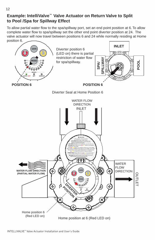
Example: IntelliValve™ Valve Actuator on Return Valve to Split to Pool /Spa for Spillway Effect
Home position at 6 (Red LED on)
To allow partial water flow to the spa/spillway port, set an end point position at 6. To allow complete water flow to spa/spillway set the other end point diverter position at 24. The valve actuator will now travel between positions 6 and 24 while normally residing at Home position 6.
Diverter Seal at Home Position 6
Diverter position 6 (LED on) there is partial restriction of water flow for spa/spillway.
POSITION 6
POSITION 6
INLET
Home position 6 (Red LED on)
WATER FLOW DIRECTION (PARTIAL WATER FLOW)
INLET
OU
TLE
T
WATER FLOW DIRECTION
WATER FLOW DIRECTION
DIVERTER
POSITION
Press MODE button to toggle between:AUTO Mode (Green LED on): The IntelliValve Valve
WARNING! DO NOT mount the IntelliValve so that the SUCTION or return line of thepump can be blocked. This will cause permanent pump damage.
Actuator is controlled automatically when connected to a
OFF Mode (Red LED on): Press SAVE button until AUTO LED is red.SET Mode (Blue LED on):
Mode changes to SERVICE (Yellow LED on). Press MODE, select AUTO.
Press or button to set endpoint
Press or button to set endpoint nearest to 24. Press SAVE.
SERVICE Mode (Yellow LED on): Use or to move valve diverterposition manually. Settings are not retained after exiting Service mode.
supported automation control system.
nearest to 0. Press SAVE.
+ to change Home position to opposite endpoint. Diverter moves to Home position (Red LED on). If required, press
PO
OL
SPA
/ S
PIL
LWA
Y

INTELLIVALVE™ Valve Actuator Installation and User’s Guide
Valve diverter seal position 24
3-Way Valve: Diverter Position vs IntelliValve™ Actuator LED positionThe following illustrates the relative position of the IntelliValve Actuator position LEDs and the 3-way valve diverter seal.
POSITION 6
Position 24 (LED on) indicates the diverter restricts water flow for total shut off of the right side outlet.
Position 0 (LED on) indicates the diverter restricts water flow for total shut off of the left side outlet.
Position 12 (LED on) indicates no water flow restriction through the left and right side outlets.
Valve diverter seal position 12
Valve diverter seal position 0
Valve diverter seal position 6
INLET
INLET
INLET
INLET
OU
TL
ET
(R
igh
t)
OU
TL
ET
(L
eft)
Position 6 (LED on) indicates the diverter partially restricts water flow out of the left side outlet.
9
99
9
99
OU
TL
ET
(R
igh
t)
OU
TL
ET
(L
eft)
OU
TL
ET
(R
igh
t)
OU
TL
ET
(L
eft)
OU
TL
ET
(R
igh
t)
OU
TL
ET
(L
eft)
13
INTELLIVALVE™ Valve Actuator Installation and User’s Guide
INLET
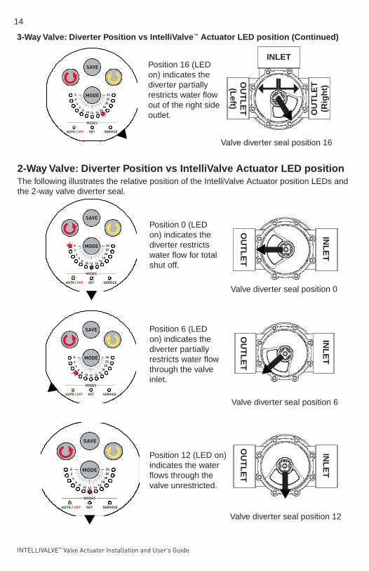
3-Way Valve: Diverter Position vs IntelliValve™ Actuator LED position (Continued)
Position 16 (LED on) indicates the diverter partially restricts water flow out of the right side outlet.
99
Valve diverter seal position 16
2-Way Valve: Diverter Position vs IntelliValve Actuator LED positionThe following illustrates the relative position of the IntelliValve Actuator position LEDs and the 2-way valve diverter seal.
Position 6 (LED on) indicates the diverter partially restricts water flow through the valve inlet.
Position 0 (LED on) indicates the diverter restricts water flow for total shut off.
INL
ET
INL
ET
OU
TL
ET
OU
TL
ET
OU
TL
ET
(R
igh
t)
OU
TL
ET
(L
eft)
Position 12 (LED on) indicates the water flows through the valve unrestricted.
INL
ET
OU
TL
ET
Valve diverter seal position 6
Valve diverter seal position 0
Valve diverter seal position 12
14

INTELLIVALVE™ Valve Actuator Installation and User’s Guide
15
3-Way Y Valve: Diverter Position vs IntelliValve™ Actuator LED positionThe following illustrates the relative position of the IntelliValve Actuator position LEDs and the 3-Way Y valve diverter seal.
Position 4 (LED on) indicates the diverter restricts water flow for total shut off of the left side outlet.
INLET
INLET
INLET
OUTLET
RIGHT
OUTLET
LEFT
OUTLET
OUTLET
OUTLET
OUTLETPosition 20 (LED on) indicates the diverter restricts water flow for total shut off of the right side outlet.
Pposition 0 (LED on) indicates the diverter partially restricts water flow out of the left side outlet. The water flow out of the right side outlet is unrestricted.
Valve diverter seal position 20
Valve diverter seal position 4
Valve diverter seal position 0

INTELLIVALVE™ Valve Actuator Installation and User’s Guide
16
INLET
INLET
Position 24 (LED on) indicates the diverter partially restricts water flow out of the right side outlet. The water flow out of the left side outlet is unrestricted.
Position 12 (LED on) indicates the diverter partially restricts water flow out of the left and right side valve.
OUTLET
OUTLET
OUTLET
OUTLET
3-Way Y Valve: Diverter Position vs IntelliValve Actuator LED position (Continued)
Valve diverter seal position 24
Valve diverter seal position 12

INTELLIVALVE™ Valve Actuator Installation and User’s Guide
Connecting Power to the IntelliValve™ Valve Actuator (EasyTouch® and IntelliTouch® Control Systems)
After the IntelliValve valve actuator is mounted on to each of the valve assemblies, connect each IntelliValve Valve Actuator 24 V power cable to the 3-pin power sockets on the automation control system circuit board.
The EasyTouch® and IntelliTouch® Control Systems can control up to four automatic valve actuators via a RS-485 four conductor connection. Two of the standard valve outputs are dedicated to the pool/spa INTAKE and RETURN valves. Valve A or Valve B actuators are for general purpose use (solar, water-feature, in-floor cleaner, etc.).
EasyTouch Control System:
1. At the Load Center route the 20 ft. IntellliValve actuator power cable up through the Load Center 1” grommet and low voltage raceway to the circuit board.
2. EasyTouch Control System Circuit Board (Return and Intake Valve): Connect the IntelliValve valve actuator power cable connector to the RETURN and/or the INTAKE (suction) 3-pin socket. If required, there are two optional valve 3-pin sockets available (Valve A and Valve B). Excess cable can be coiled in the enclosure low voltage raceway left side compartment. Do not coil the conductor in upper low voltage compartment. For valve actuator circuit board socket location see diagram below.
BEFORE INSTALLATION OR SERVICING THE INTELLIVALVE® VALVE ACTUATOR - Always disconnect power at the circuit breaker before servicing. Failure to do so could result in death or serious injury to service person, pool users or others due to electric shock.
NOTE: This device must be installed by a licensed or certified electrician or a qualified pool professional in accordance with the National Electrical Code (NEC), NFPA 70 or the Canadian Electrical Code (CEC), CSA C22.1.
EasyTouch Control System Circuit Board
EasyTouch Control System Circuit Board
17
Connect IntelliValve power cable connector
to Return and Intake valve 3-pin Socket

INTELLIVALVE™ Valve Actuator Installation and User’s Guide
1. IntelliTouch Control System Personality: (Intake and Return Valve): Connect the IntelliValve valve actuator power cable connector to the INTAKE (suction) and/or RETURN 3-pin socket. If required, there are two optional valve 3-pin sockets available (Valve A and Valve B). Excess cable can be coiled in the enclosure low voltage raceway left side compartment. Do not coil the conductor in upper low voltage compartment. For valve actuator circuit board socket location see diagram below.
Note: IntelliTouch Control System Optional Valve Module Expansion Board: Using a Valve Module Expansion board (P/N 520285), three additional valve actuators (VALVE C, D and E) can be added to the system. The expansion board attaches to the edge of the IntelliTouch Personality board. For installation and operation information, refer to the IntelliTouch Valve Actuator Installation Guide (P/N 520294).
Test the IntelliValve Valve Actuators:
Switch on power to the control system at the circuit breaker and verify that the IntelliValve valve actuator are operating correctly.
IntelliTouch Personality Circuit Board
IntelliTouch® Control System:
IntelliTouch Control System Circuit Board
18
Connect IntelliValve power cable connector
to Intake and Return valve 3-pin Socket

INTELLIVALVE™ Valve Actuator Installation and User’s Guide
19
Problem: The IntelliValve actuator did not move or went back to the previous position when the circuit was activated. Action: Be sure that both end point positions are set. If not, reset both end points (see Set Mode on page 9). If only one end point diverter position was set, the actuator will revert to previous setting.
Problem: How do I reverse the end points? As in it’s stopping in the opposite position, what did I do wrong? Action: To change the Home position: When in AUTO mode, press the Red arrow button and Yellow arrow button simultaneously. The diverter will rotate to the other end point (the new home position). The factory default home position is 0. See page 11 for more information. Problem: Unit is not able to move to assigned position (stuck). Power LED is blinking Red and Green and the Service orange LED is on. The IntelliValve Valve Actuator is not designed to be used in applications that involve prolonged continuous operation, such as water features that demand continuous diverter movement. Action: Press the Mode button. The unit should return to normal operation.
Problem: The valve is not rotating when automation tells it to. Action: Check that the IntelliValve actuator is in AUTO mode.
FAQ: What are these green and yellow communication wires for? These are reserved for future use with future automation systems.
Troubleshooting

INTELLIVALVE™ Valve Actuator Installation and User’s Guide*522301*
20
1620 HAWKINS AVE., SANFORD, NC 27330 • (919) 566-800010951 WEST LOS ANGELES AVE., MOORPARK, CA 93021 • (805) 553-5000 WWW.PENTAIRPOOL.COMAll Pentair trademarks and logos are owned by Pentair or one of its global affiliates. Pentair Aquatic Systems®, IntelliValve™, EasyTouch®, IntelliTouch®, and SunTouch® are trademarks and/or registered trademarks of Pentair Water Pool and Spa, Inc. and/or its affiliated companies in the United States and/ or other countries. Unless expressly noted, names and brands of third parties that may be used in this document are not used to indicate an affiliation or endorsement between the owners of these names and brands and Pentair Water Pool and Spa, Inc. Those names and brands may be the trademarks or registered trademarks of those third parties. Because we are continuously improving our products and services, Pentair reserves the right to change specifications without prior notice. Pentair is an equal opportunity employer.© 2015 Pentair Water Pool and Spa, Inc. All rights reserved. This document is subject to change without notice.
P/N 522301 REV. B 12/2015
Recommended