Reference Manual 00809-0100-4662, Rev BA
August 2007
Rosemount 8732EIntegral Mount Magnetic Flowmeter System
www.rosemount.com


Reference Manual 00809-0100-4662, Rev BA
August 2007 Rosemount 8732
Integral Mount Magnetic Flowmeter System
NOTICE
Read this manual before working with the product. For personal and system safety, and for
optimum product performance, make sure you thoroughly understand the contents before
installing, using, or maintaining this product.
Rosemount Inc. has two toll-free assistance numbers:
Customer CentralTechnical support, quoting, and order-related questions.
United States - 1-800-999-9307 (7:00 am to 7:00 pm CST)
Asia Pacific- 65 777 8211
Europe/ Middle East/ Africa - 49 (8153) 9390
North American Response CenterEquipment service needs.
1-800-654-7768 (24 hours—includes Canada)
Outside of these areas, contact your local Rosemount representative.
The products described in this document are NOT designed for nuclear-qualified
applications. Using non-nuclear qualified products in applications that require
nuclear-qualified hardware or products may cause inaccurate readings.
For information on Rosemount nuclear-qualified products, contact your local Rosemount
Sales Representative.
www.rosemount.com

Reference Manual 00809-0100-4662, Rev BA
August 2007 Rosemount 8732
Table of Contents
SECTION 1Introduction
System Description . . . . . . . . . . . . . . . . . . . . . . . . . . . . . . . . . . . . . . . 1-1
Safety Messages . . . . . . . . . . . . . . . . . . . . . . . . . . . . . . . . . . . . . . . . . 1-2
Service Support . . . . . . . . . . . . . . . . . . . . . . . . . . . . . . . . . . . . . . . . . . 1-2
SECTION 2Installation
Safety Messages . . . . . . . . . . . . . . . . . . . . . . . . . . . . . . . . . . . . . . . . . 2-1
Transmitter Symbols . . . . . . . . . . . . . . . . . . . . . . . . . . . . . . . . . . . . . . 2-2
Pre-Installation. . . . . . . . . . . . . . . . . . . . . . . . . . . . . . . . . . . . . . . . . . . 2-2
Mechanical Considerations . . . . . . . . . . . . . . . . . . . . . . . . . . . . . . 2-2
Environmental Considerations . . . . . . . . . . . . . . . . . . . . . . . . . . . . 2-3
Installation Procedures . . . . . . . . . . . . . . . . . . . . . . . . . . . . . . . . . . . . 2-3
Mount the Transmitter . . . . . . . . . . . . . . . . . . . . . . . . . . . . . . . . . . 2-3
Pipe Mounting . . . . . . . . . . . . . . . . . . . . . . . . . . . . . . . . . . . . . . 2-3
Surface Mounting . . . . . . . . . . . . . . . . . . . . . . . . . . . . . . . . . . . 2-4
Identify Options and Configurations . . . . . . . . . . . . . . . . . . . . . . . . 2-4
Hardware Switches. . . . . . . . . . . . . . . . . . . . . . . . . . . . . . . . . . . . . 2-4
Failure Alarm Mode . . . . . . . . . . . . . . . . . . . . . . . . . . . . . . . . . . 2-4
Internal/External Analog Power. . . . . . . . . . . . . . . . . . . . . . . . . 2-4
Transmitter Security . . . . . . . . . . . . . . . . . . . . . . . . . . . . . . . . . 2-5
Internal/External Pulse Power . . . . . . . . . . . . . . . . . . . . . . . . . . 2-5
Changing Hardware Switch Settings. . . . . . . . . . . . . . . . . . . . . 2-5
Conduit Ports and Connections . . . . . . . . . . . . . . . . . . . . . . . . . . . 2-6
Conduit Cables . . . . . . . . . . . . . . . . . . . . . . . . . . . . . . . . . . . . . . . . 2-6
Electrical Considerations . . . . . . . . . . . . . . . . . . . . . . . . . . . . . . . . 2-7
Transmitter Input Power . . . . . . . . . . . . . . . . . . . . . . . . . . . . . . 2-7
Requirements for 90-250 V AC Power Supply . . . . . . . . . . . . . 2-7
Requirements for 12-42 V DC Power Supply . . . . . . . . . . . . . . 2-7
Installation Category. . . . . . . . . . . . . . . . . . . . . . . . . . . . . . . . . . . . 2-9
Overcurrent Protection . . . . . . . . . . . . . . . . . . . . . . . . . . . . . . . . . . 2-9
Options, Considerations, and Procedures . . . . . . . . . . . . . . . . . . . . . . 2-9
Connect Transmitter Power . . . . . . . . . . . . . . . . . . . . . . . . . . . . . . 2-9
Connect 4–20 mA Loop External Power Source . . . . . . . . . . . . . 2-10
Connect Pulse Output Power Source. . . . . . . . . . . . . . . . . . . . . . 2-11
External . . . . . . . . . . . . . . . . . . . . . . . . . . . . . . . . . . . . . . . . . . 2-11
Internal . . . . . . . . . . . . . . . . . . . . . . . . . . . . . . . . . . . . . . . . . . 2-11
Connect Digital Output . . . . . . . . . . . . . . . . . . . . . . . . . . . . . . . . . 2-13
Connect Digital Input . . . . . . . . . . . . . . . . . . . . . . . . . . . . . . . . . . 2-14
Flowtube Sensor Connections. . . . . . . . . . . . . . . . . . . . . . . . . . . . . . 2-16
Rosemount Flowtube Sensors . . . . . . . . . . . . . . . . . . . . . . . . . . . 2-16
Transmitter to
Flowtube Sensor Wiring . . . . . . . . . . . . . . . . . . . . . . . . . . . . . . . . 2-16
Conduit Cables . . . . . . . . . . . . . . . . . . . . . . . . . . . . . . . . . . . . . . . 2-17
Flowtube Sensor to Remote Mount Transmitter Connections . . . 2-18
www.emersonprocess.com/rosemount
Reference Manual00809-0100-4662, Rev BA
August 2007Rosemount 8732
SECTION 3Configuration
Introduction . . . . . . . . . . . . . . . . . . . . . . . . . . . . . . . . . . . . . . . . . . . . . 3-1
Local Operator Interface . . . . . . . . . . . . . . . . . . . . . . . . . . . . . . . . . . . 3-1
Basic Features. . . . . . . . . . . . . . . . . . . . . . . . . . . . . . . . . . . . . . . . . . . 3-1
Data Entry. . . . . . . . . . . . . . . . . . . . . . . . . . . . . . . . . . . . . . . . . . . . 3-2
LOI Examples . . . . . . . . . . . . . . . . . . . . . . . . . . . . . . . . . . . . . . . . . . . 3-2
Table Value Example . . . . . . . . . . . . . . . . . . . . . . . . . . . . . . . . . . . 3-3
Select Value Example . . . . . . . . . . . . . . . . . . . . . . . . . . . . . . . . . . 3-3
Diagnostic Messages. . . . . . . . . . . . . . . . . . . . . . . . . . . . . . . . . . . . . . 3-5
Review . . . . . . . . . . . . . . . . . . . . . . . . . . . . . . . . . . . . . . . . . . . . . . 3-5
Process Variables . . . . . . . . . . . . . . . . . . . . . . . . . . . . . . . . . . . . . . . . 3-5
PV - Primary Variable . . . . . . . . . . . . . . . . . . . . . . . . . . . . . . . . . . . 3-6
PV -% Range . . . . . . . . . . . . . . . . . . . . . . . . . . . . . . . . . . . . . . . . . 3-6
PV - Analog Output. . . . . . . . . . . . . . . . . . . . . . . . . . . . . . . . . . . . . 3-6
Totalizer Setup . . . . . . . . . . . . . . . . . . . . . . . . . . . . . . . . . . . . . . . . 3-6
Totalizer Units . . . . . . . . . . . . . . . . . . . . . . . . . . . . . . . . . . . . . . 3-6
Measured Gross Total. . . . . . . . . . . . . . . . . . . . . . . . . . . . . . . . 3-6
Measured Net Total. . . . . . . . . . . . . . . . . . . . . . . . . . . . . . . . . . 3-6
Measured Reverse Total . . . . . . . . . . . . . . . . . . . . . . . . . . . . . . 3-7
Start Totalizer . . . . . . . . . . . . . . . . . . . . . . . . . . . . . . . . . . . . . . 3-7
Stop Totalizer . . . . . . . . . . . . . . . . . . . . . . . . . . . . . . . . . . . . . . 3-7
Reset Totalizer . . . . . . . . . . . . . . . . . . . . . . . . . . . . . . . . . . . . . 3-7
Pulse Output. . . . . . . . . . . . . . . . . . . . . . . . . . . . . . . . . . . . . . . . . . 3-7
Basic Setup . . . . . . . . . . . . . . . . . . . . . . . . . . . . . . . . . . . . . . . . . . . . . 3-7
Tag . . . . . . . . . . . . . . . . . . . . . . . . . . . . . . . . . . . . . . . . . . . . . . . . . 3-7
Flow Units. . . . . . . . . . . . . . . . . . . . . . . . . . . . . . . . . . . . . . . . . . . . 3-7
Primary Variable Units. . . . . . . . . . . . . . . . . . . . . . . . . . . . . . . . 3-7
Special Units . . . . . . . . . . . . . . . . . . . . . . . . . . . . . . . . . . . . . . . 3-8
Line Size. . . . . . . . . . . . . . . . . . . . . . . . . . . . . . . . . . . . . . . . . . . . . 3-9
PV URV (Upper Range Value) . . . . . . . . . . . . . . . . . . . . . . . . . . . 3-10
PV LRV (Lower Range Value) . . . . . . . . . . . . . . . . . . . . . . . . . . . 3-10
Example . . . . . . . . . . . . . . . . . . . . . . . . . . . . . . . . . . . . . . . . . 3-10
Calibration Number. . . . . . . . . . . . . . . . . . . . . . . . . . . . . . . . . . . . 3-11
PV Damping . . . . . . . . . . . . . . . . . . . . . . . . . . . . . . . . . . . . . . . . . 3-11
SECTION 4Operation
Introduction . . . . . . . . . . . . . . . . . . . . . . . . . . . . . . . . . . . . . . . . . . . . . 4-1
Diagnostics . . . . . . . . . . . . . . . . . . . . . . . . . . . . . . . . . . . . . . . . . . . . . 4-1
Diagnostic Controls . . . . . . . . . . . . . . . . . . . . . . . . . . . . . . . . . . . . 4-1
Empty Pipe . . . . . . . . . . . . . . . . . . . . . . . . . . . . . . . . . . . . . . . . 4-2
High Process Noise. . . . . . . . . . . . . . . . . . . . . . . . . . . . . . . . . . 4-2
Grounding / Wiring . . . . . . . . . . . . . . . . . . . . . . . . . . . . . . . . . . 4-2
Electronics Temperature . . . . . . . . . . . . . . . . . . . . . . . . . . . . . . 4-2
Basic Diagnostics . . . . . . . . . . . . . . . . . . . . . . . . . . . . . . . . . . . . . . 4-2
Self Test . . . . . . . . . . . . . . . . . . . . . . . . . . . . . . . . . . . . . . . . . . 4-2
AO Loop Test . . . . . . . . . . . . . . . . . . . . . . . . . . . . . . . . . . . . . . 4-2
Pulse Output Loop Test. . . . . . . . . . . . . . . . . . . . . . . . . . . . . . . 4-3
Empty Pipe Limits . . . . . . . . . . . . . . . . . . . . . . . . . . . . . . . . . . . 4-3
Electronics Temperature . . . . . . . . . . . . . . . . . . . . . . . . . . . . . . 4-4
Advanced Diagnostics . . . . . . . . . . . . . . . . . . . . . . . . . . . . . . . . . . 4-4
8714i Calibration Verification™ . . . . . . . . . . . . . . . . . . . . . . . . . 4-4
4-20 mA Verify. . . . . . . . . . . . . . . . . . . . . . . . . . . . . . . . . . . . . . 4-8
Licensing . . . . . . . . . . . . . . . . . . . . . . . . . . . . . . . . . . . . . . . . . . 4-8
TOC-2
Reference Manual 00809-0100-4662, Rev BA
August 2007 Rosemount 8732
Diagnostic Variable Values. . . . . . . . . . . . . . . . . . . . . . . . . . . . . . . 4-8
Empty Pipe Value . . . . . . . . . . . . . . . . . . . . . . . . . . . . . . . . . . . 4-8
Electronics Temperature . . . . . . . . . . . . . . . . . . . . . . . . . . . . . . 4-9
Line Noise . . . . . . . . . . . . . . . . . . . . . . . . . . . . . . . . . . . . . . . . . 4-9
5 Hz Signal to Noise Ratio . . . . . . . . . . . . . . . . . . . . . . . . . . . . 4-9
37 Hz Signal to Noise Ratio . . . . . . . . . . . . . . . . . . . . . . . . . . . 4-9
Signal Power . . . . . . . . . . . . . . . . . . . . . . . . . . . . . . . . . . . . . . . 4-9
8714i Results. . . . . . . . . . . . . . . . . . . . . . . . . . . . . . . . . . . . . . . 4-9
Trims. . . . . . . . . . . . . . . . . . . . . . . . . . . . . . . . . . . . . . . . . . . . . . . 4-10
D/A Trim . . . . . . . . . . . . . . . . . . . . . . . . . . . . . . . . . . . . . . . . . 4-11
Scaled D/A Trim . . . . . . . . . . . . . . . . . . . . . . . . . . . . . . . . . . . 4-11
Digital Trim . . . . . . . . . . . . . . . . . . . . . . . . . . . . . . . . . . . . . . . 4-11
Auto Zero. . . . . . . . . . . . . . . . . . . . . . . . . . . . . . . . . . . . . . . . . 4-12
Universal Trim . . . . . . . . . . . . . . . . . . . . . . . . . . . . . . . . . . . . . 4-13
Status . . . . . . . . . . . . . . . . . . . . . . . . . . . . . . . . . . . . . . . . . . . . . . 4-13
Advanced Configuration . . . . . . . . . . . . . . . . . . . . . . . . . . . . . . . . . . 4-13
Detailed Setup . . . . . . . . . . . . . . . . . . . . . . . . . . . . . . . . . . . . . . . . . . 4-13
Additional Parameters . . . . . . . . . . . . . . . . . . . . . . . . . . . . . . . . . 4-13
Coil Drive Frequency. . . . . . . . . . . . . . . . . . . . . . . . . . . . . . . . 4-13
5 Hz . . . . . . . . . . . . . . . . . . . . . . . . . . . . . . . . . . . . . . . . . . . . . 4-13
37 Hz . . . . . . . . . . . . . . . . . . . . . . . . . . . . . . . . . . . . . . . . . . . . 4-13
Density Value . . . . . . . . . . . . . . . . . . . . . . . . . . . . . . . . . . . . . 4-13
PV Upper Sensor Limit (USL) . . . . . . . . . . . . . . . . . . . . . . . . . 4-14
PV Lower Sensor Limit (LSL) . . . . . . . . . . . . . . . . . . . . . . . . . 4-14
PV Minimum Span. . . . . . . . . . . . . . . . . . . . . . . . . . . . . . . . . . 4-14
Configure Outputs . . . . . . . . . . . . . . . . . . . . . . . . . . . . . . . . . . . . 4-14
Analog Output . . . . . . . . . . . . . . . . . . . . . . . . . . . . . . . . . . . . . 4-14
Pulse Output . . . . . . . . . . . . . . . . . . . . . . . . . . . . . . . . . . . . . . 4-17
Digital Input / Digital Output. . . . . . . . . . . . . . . . . . . . . . . . . . . 4-20
Reverse Flow . . . . . . . . . . . . . . . . . . . . . . . . . . . . . . . . . . . . . 4-20
Totalizer Setup . . . . . . . . . . . . . . . . . . . . . . . . . . . . . . . . . . . . 4-20
Alarm Level . . . . . . . . . . . . . . . . . . . . . . . . . . . . . . . . . . . . . . . 4-21
HART Output. . . . . . . . . . . . . . . . . . . . . . . . . . . . . . . . . . . . . . 4-22
LOI Configuration . . . . . . . . . . . . . . . . . . . . . . . . . . . . . . . . . . . . . 4-24
Language . . . . . . . . . . . . . . . . . . . . . . . . . . . . . . . . . . . . . . . . 4-24
Flowrate Display . . . . . . . . . . . . . . . . . . . . . . . . . . . . . . . . . . . 4-24
Totalizer Display . . . . . . . . . . . . . . . . . . . . . . . . . . . . . . . . . . . 4-24
Display Lock . . . . . . . . . . . . . . . . . . . . . . . . . . . . . . . . . . . . . . 4-24
Signal Processing. . . . . . . . . . . . . . . . . . . . . . . . . . . . . . . . . . . . . 4-25
Operating Mode. . . . . . . . . . . . . . . . . . . . . . . . . . . . . . . . . . . . 4-25
Manually Configure Digital Signal Processing (DSP) . . . . . . . 4-25
Coil Drive Frequency. . . . . . . . . . . . . . . . . . . . . . . . . . . . . . . . 4-26
5 Hz . . . . . . . . . . . . . . . . . . . . . . . . . . . . . . . . . . . . . . . . . . . . . 4-26
37 Hz . . . . . . . . . . . . . . . . . . . . . . . . . . . . . . . . . . . . . . . . . . . . 4-26
Low Flow Cutoff. . . . . . . . . . . . . . . . . . . . . . . . . . . . . . . . . . . . 4-26
Primary Variable Damping . . . . . . . . . . . . . . . . . . . . . . . . . . . 4-26
Universal Auto Trim . . . . . . . . . . . . . . . . . . . . . . . . . . . . . . . . . . . 4-27
TOC-3
Reference Manual00809-0100-4662, Rev BA
August 2007Rosemount 8732
Device Info . . . . . . . . . . . . . . . . . . . . . . . . . . . . . . . . . . . . . . . . . . 4-27
Manufacturer . . . . . . . . . . . . . . . . . . . . . . . . . . . . . . . . . . . . . . 4-27
Tag . . . . . . . . . . . . . . . . . . . . . . . . . . . . . . . . . . . . . . . . . . . . . 4-27
Descriptor . . . . . . . . . . . . . . . . . . . . . . . . . . . . . . . . . . . . . . . . 4-27
Message . . . . . . . . . . . . . . . . . . . . . . . . . . . . . . . . . . . . . . . . . 4-27
Date. . . . . . . . . . . . . . . . . . . . . . . . . . . . . . . . . . . . . . . . . . . . . 4-27
Device ID. . . . . . . . . . . . . . . . . . . . . . . . . . . . . . . . . . . . . . . . . 4-28
Flowtube Sensor Serial Number . . . . . . . . . . . . . . . . . . . . . . . 4-28
Flowtube Sensor Tag . . . . . . . . . . . . . . . . . . . . . . . . . . . . . . . 4-28
Write Protect . . . . . . . . . . . . . . . . . . . . . . . . . . . . . . . . . . . . . . 4-28
Revision Numbers . . . . . . . . . . . . . . . . . . . . . . . . . . . . . . . . . . 4-28
Construction Materials. . . . . . . . . . . . . . . . . . . . . . . . . . . . . . . 4-29
SECTION 5Flowtube Installation
Safety Messages . . . . . . . . . . . . . . . . . . . . . . . . . . . . . . . . . . . . . . . . . 5-1
Flowtube Handling . . . . . . . . . . . . . . . . . . . . . . . . . . . . . . . . . . . . . . . . 5-3
Flowtube Mounting . . . . . . . . . . . . . . . . . . . . . . . . . . . . . . . . . . . . . . . 5-4
Upstream/Downstream
Piping . . . . . . . . . . . . . . . . . . . . . . . . . . . . . . . . . . . . . . . . . . . . . . . 5-4
Flowtube Orientation . . . . . . . . . . . . . . . . . . . . . . . . . . . . . . . . . . . 5-4
Flow Direction. . . . . . . . . . . . . . . . . . . . . . . . . . . . . . . . . . . . . . . . . 5-6
Installation (Flanged Flowtube) . . . . . . . . . . . . . . . . . . . . . . . . . . . . . . 5-7
Gaskets . . . . . . . . . . . . . . . . . . . . . . . . . . . . . . . . . . . . . . . . . . . . . 5-7
Flange Bolts . . . . . . . . . . . . . . . . . . . . . . . . . . . . . . . . . . . . . . . . . . 5-7
Installation
(Wafer Flowtube) . . . . . . . . . . . . . . . . . . . . . . . . . . . . . . . . . . . . . . . . 5-10
Gaskets . . . . . . . . . . . . . . . . . . . . . . . . . . . . . . . . . . . . . . . . . . . . 5-10
Flange Bolts . . . . . . . . . . . . . . . . . . . . . . . . . . . . . . . . . . . . . . . . . 5-11
Installation
(Sanitary Flowtube) . . . . . . . . . . . . . . . . . . . . . . . . . . . . . . . . . . . . . . 5-12
Gaskets . . . . . . . . . . . . . . . . . . . . . . . . . . . . . . . . . . . . . . . . . . . . 5-12
Alignment and Bolting. . . . . . . . . . . . . . . . . . . . . . . . . . . . . . . . . . 5-12
Grounding . . . . . . . . . . . . . . . . . . . . . . . . . . . . . . . . . . . . . . . . . . . . . 5-12
Process Leak Protection (Optional) . . . . . . . . . . . . . . . . . . . . . . . . . . 5-16
Standard Housing Configuration . . . . . . . . . . . . . . . . . . . . . . . . . 5-16
Relief Valves. . . . . . . . . . . . . . . . . . . . . . . . . . . . . . . . . . . . . . . . . 5-17
Process Leak Containment . . . . . . . . . . . . . . . . . . . . . . . . . . . . . 5-17
SECTION 6Maintenance and Troubleshooting
Safety Information . . . . . . . . . . . . . . . . . . . . . . . . . . . . . . . . . . . . . . . . 6-1
Installation Check and Guide. . . . . . . . . . . . . . . . . . . . . . . . . . . . . . . . 6-2
Before You Begin . . . . . . . . . . . . . . . . . . . . . . . . . . . . . . . . . . . 6-2
Transmitter . . . . . . . . . . . . . . . . . . . . . . . . . . . . . . . . . . . . . . . . 6-2
Flowtube . . . . . . . . . . . . . . . . . . . . . . . . . . . . . . . . . . . . . . . . . . 6-2
Wiring . . . . . . . . . . . . . . . . . . . . . . . . . . . . . . . . . . . . . . . . . . . . 6-2
Process Fluid. . . . . . . . . . . . . . . . . . . . . . . . . . . . . . . . . . . . . . . 6-2
Diagnostic Messages. . . . . . . . . . . . . . . . . . . . . . . . . . . . . . . . . . . . . . 6-3
Transmitter Troubleshooting . . . . . . . . . . . . . . . . . . . . . . . . . . . . . . . . 6-7
Quick Troubleshooting. . . . . . . . . . . . . . . . . . . . . . . . . . . . . . . . . . . . . 6-9
Step 1: Wiring Errors . . . . . . . . . . . . . . . . . . . . . . . . . . . . . . . . . . . 6-9
Step 2: Process Noise . . . . . . . . . . . . . . . . . . . . . . . . . . . . . . . . . . 6-9
Step 3: Installed Flowtube Tests . . . . . . . . . . . . . . . . . . . . . . . . . 6-10
Step 4: Uninstalled Flowtube Tests . . . . . . . . . . . . . . . . . . . . . . . 6-11
TOC-4
Reference Manual 00809-0100-4662, Rev BA
August 2007 Rosemount 8732
APPENDIX AReference Data
Rosemount 8732E Transmitter Specifications. . . . . . . . . . . . . . . . . . .A-1
Functional Specifications . . . . . . . . . . . . . . . . . . . . . . . . . . . . . . . .A-1
Flowtube Sensor Compatibility . . . . . . . . . . . . . . . . . . . . . . . . .A-1
Flowtube Sensor Coil Resistance . . . . . . . . . . . . . . . . . . . . . . .A-1
Flow Rate Range. . . . . . . . . . . . . . . . . . . . . . . . . . . . . . . . . . . .A-1
Conductivity Limits . . . . . . . . . . . . . . . . . . . . . . . . . . . . . . . . . .A-1
Power Supply . . . . . . . . . . . . . . . . . . . . . . . . . . . . . . . . . . . . . .A-1
AC Power Supply Requirements. . . . . . . . . . . . . . . . . . . . . . . .A-2
DC Load Limitations (Analog Output) . . . . . . . . . . . . . . . . . . . .A-2
DC Supply Current Requirements. . . . . . . . . . . . . . . . . . . . . . .A-3
Installation Coordination . . . . . . . . . . . . . . . . . . . . . . . . . . . . . .A-3
Power Consumption . . . . . . . . . . . . . . . . . . . . . . . . . . . . . . . . .A-3
Ambient Temperature Limits . . . . . . . . . . . . . . . . . . . . . . . . . . .A-3
Humidity Limits . . . . . . . . . . . . . . . . . . . . . . . . . . . . . . . . . . . . .A-3
Enclosure Rating . . . . . . . . . . . . . . . . . . . . . . . . . . . . . . . . . . . .A-3
Output Signals. . . . . . . . . . . . . . . . . . . . . . . . . . . . . . . . . . . . . .A-3
Software Lockout. . . . . . . . . . . . . . . . . . . . . . . . . . . . . . . . . . . .A-4
Display Lockout . . . . . . . . . . . . . . . . . . . . . . . . . . . . . . . . . . . . .A-4
Output Testing. . . . . . . . . . . . . . . . . . . . . . . . . . . . . . . . . . . . . .A-4
Turn-on Time. . . . . . . . . . . . . . . . . . . . . . . . . . . . . . . . . . . . . . .A-4
Start-up Time. . . . . . . . . . . . . . . . . . . . . . . . . . . . . . . . . . . . . . .A-4
Low Flow Cutoff. . . . . . . . . . . . . . . . . . . . . . . . . . . . . . . . . . . . .A-4
Overrange Capability. . . . . . . . . . . . . . . . . . . . . . . . . . . . . . . . .A-4
Damping . . . . . . . . . . . . . . . . . . . . . . . . . . . . . . . . . . . . . . . . . .A-4
Flowtube Sensor Compensation . . . . . . . . . . . . . . . . . . . . . . . .A-4
Diagnostics . . . . . . . . . . . . . . . . . . . . . . . . . . . . . . . . . . . . . . . .A-5
Performance Specifications . . . . . . . . . . . . . . . . . . . . . . . . . . . . . .A-5
Accuracy . . . . . . . . . . . . . . . . . . . . . . . . . . . . . . . . . . . . . . . . . .A-5
Analog Output Effect . . . . . . . . . . . . . . . . . . . . . . . . . . . . . . . . .A-5
Vibration Effect . . . . . . . . . . . . . . . . . . . . . . . . . . . . . . . . . . . . .A-5
Repeatability . . . . . . . . . . . . . . . . . . . . . . . . . . . . . . . . . . . . . . .A-6
Response Time (Analog Output). . . . . . . . . . . . . . . . . . . . . . . .A-6
Stability . . . . . . . . . . . . . . . . . . . . . . . . . . . . . . . . . . . . . . . . . . .A-6
Ambient Temperature Effect . . . . . . . . . . . . . . . . . . . . . . . . . . .A-6
EMC Compliance . . . . . . . . . . . . . . . . . . . . . . . . . . . . . . . . . . .A-6
Dead Time. . . . . . . . . . . . . . . . . . . . . . . . . . . . . . . . . . . . . . . . .A-6
TOC-5
Reference Manual00809-0100-4662, Rev BA
August 2007Rosemount 8732
Physical Specifications . . . . . . . . . . . . . . . . . . . . . . . . . . . . . . . . . .A-6
Materials of Construction. . . . . . . . . . . . . . . . . . . . . . . . . . . . . .A-6
Electrical Connections. . . . . . . . . . . . . . . . . . . . . . . . . . . . . . . .A-6
Transmitter Weight . . . . . . . . . . . . . . . . . . . . . . . . . . . . . . . . . .A-6
Rosemount 8712D/H Transmitter Specifications . . . . . . . . . . .A-7
Flowtube Sensor Compatibility . . . . . . . . . . . . . . . . . . . . . . . . .A-7
Flow Rate Range. . . . . . . . . . . . . . . . . . . . . . . . . . . . . . . . . . . .A-7
Conductivity Limits . . . . . . . . . . . . . . . . . . . . . . . . . . . . . . . . . .A-7
DC Load Limitations (Analog Output) . . . . . . . . . . . . . . . . . . . .A-7
Supply Current Requirements (8712D) . . . . . . . . . . . . . . . . . . .A-8
Installation Coordination . . . . . . . . . . . . . . . . . . . . . . . . . . . . . .A-8
Power Consumption . . . . . . . . . . . . . . . . . . . . . . . . . . . . . . . . .A-8
Ambient Temperature Limits . . . . . . . . . . . . . . . . . . . . . . . . . . .A-8
Humidity Limits . . . . . . . . . . . . . . . . . . . . . . . . . . . . . . . . . . . . .A-8
Enclosure Ratings . . . . . . . . . . . . . . . . . . . . . . . . . . . . . . . . . . .A-8
Output Signals. . . . . . . . . . . . . . . . . . . . . . . . . . . . . . . . . . . . . .A-8
Software Lockout. . . . . . . . . . . . . . . . . . . . . . . . . . . . . . . . . . . .A-9
Output Testing. . . . . . . . . . . . . . . . . . . . . . . . . . . . . . . . . . . . . .A-9
Turn-on Time. . . . . . . . . . . . . . . . . . . . . . . . . . . . . . . . . . . . . . .A-9
Start-up Time. . . . . . . . . . . . . . . . . . . . . . . . . . . . . . . . . . . . . . .A-9
Low Flow Cutoff. . . . . . . . . . . . . . . . . . . . . . . . . . . . . . . . . . . . .A-9
Overrange Capability. . . . . . . . . . . . . . . . . . . . . . . . . . . . . . . . .A-9
Damping . . . . . . . . . . . . . . . . . . . . . . . . . . . . . . . . . . . . . . . . . .A-9
Flowtube Sensor Compensation . . . . . . . . . . . . . . . . . . . . . . .A-10
Performance Specifications . . . . . . . . . . . . . . . . . . . . . . . . . . . . .A-10
Accuracy . . . . . . . . . . . . . . . . . . . . . . . . . . . . . . . . . . . . . . . . .A-10
Analog Output Effect . . . . . . . . . . . . . . . . . . . . . . . . . . . . . . . .A-10
Vibration Effect . . . . . . . . . . . . . . . . . . . . . . . . . . . . . . . . . . . .A-10
Repeatability . . . . . . . . . . . . . . . . . . . . . . . . . . . . . . . . . . . . . .A-10
Response Time . . . . . . . . . . . . . . . . . . . . . . . . . . . . . . . . . . . .A-11
Stability . . . . . . . . . . . . . . . . . . . . . . . . . . . . . . . . . . . . . . . . . .A-11
Ambient Temperature Effect . . . . . . . . . . . . . . . . . . . . . . . . . .A-12
Physical Specifications . . . . . . . . . . . . . . . . . . . . . . . . . . . . . . . . .A-12
Materials of Construction. . . . . . . . . . . . . . . . . . . . . . . . . . . . .A-12
Electrical Connections. . . . . . . . . . . . . . . . . . . . . . . . . . . . . . .A-12
Rosemount 8742C Transmitter Specifications . . . . . . . . . . . .A-13
Flowtube Sensor Compatibility . . . . . . . . . . . . . . . . . . . . . . . .A-13
Conductivity Limits . . . . . . . . . . . . . . . . . . . . . . . . . . . . . . . . .A-13
Flowtube Sensor Coil Resistance . . . . . . . . . . . . . . . . . . . . . .A-13
Flow Rate Range. . . . . . . . . . . . . . . . . . . . . . . . . . . . . . . . . . .A-13
Power Supply . . . . . . . . . . . . . . . . . . . . . . . . . . . . . . . . . . . . .A-13
Supply Current Requirements . . . . . . . . . . . . . . . . . . . . . . . . .A-13
Installation Coordination . . . . . . . . . . . . . . . . . . . . . . . . . . . . .A-13
Power Consumption . . . . . . . . . . . . . . . . . . . . . . . . . . . . . . . .A-13
Ambient Temperature Limits . . . . . . . . . . . . . . . . . . . . . . . . . .A-13
Humidity Limits . . . . . . . . . . . . . . . . . . . . . . . . . . . . . . . . . . . .A-13
Enclosure Rating . . . . . . . . . . . . . . . . . . . . . . . . . . . . . . . . . . .A-14
Output Signal. . . . . . . . . . . . . . . . . . . . . . . . . . . . . . . . . . . . . .A-14
Foundation™ Fieldbus Specifications . . . . . . . . . . . . . . . . . . . . . .A-14
Schedule Entries . . . . . . . . . . . . . . . . . . . . . . . . . . . . . . . . . . .A-14
Links . . . . . . . . . . . . . . . . . . . . . . . . . . . . . . . . . . . . . . . . . . . .A-14
Virtual Communications Relationships (VCRs) . . . . . . . . . . . .A-14
Performance Specifications . . . . . . . . . . . . . . . . . . . . . . . . . . . . .A-15
TOC-6
Reference Manual 00809-0100-4662, Rev BA
August 2007 Rosemount 8732
Physical Specifications . . . . . . . . . . . . . . . . . . . . . . . . . . . . . . . . .A-15
Electrical Connections. . . . . . . . . . . . . . . . . . . . . . . . . . . . . . .A-16
Mounting . . . . . . . . . . . . . . . . . . . . . . . . . . . . . . . . . . . . . . . . .A-16
Weight . . . . . . . . . . . . . . . . . . . . . . . . . . . . . . . . . . . . . . . . . . .A-16
Rosemount 8705 Flanged and 8707
High-Signal Flanged Flowtube Sensors Specifications. . . . . .A-17
Ambient Temperature Limits . . . . . . . . . . . . . . . . . . . . . . . . . .A-17
Physical Specifications . . . . . . . . . . . . . . . . . . . . . . . . . . . . . . . . .A-20
Rosemount 8711 Wafer Flowtube Sensor Specifications . . . .A-23
Performance Specifications . . . . . . . . . . . . . . . . . . . . . . . . . . . . .A-24
Physical Specifications . . . . . . . . . . . . . . . . . . . . . . . . . . . . . . . . .A-24
Rosemount 8721 Sanitary Flowtube Sensor Specifications . .A-26
Performance Specifications . . . . . . . . . . . . . . . . . . . . . . . . . . . . .A-27
Physical Specifications . . . . . . . . . . . . . . . . . . . . . . . . . . . . . . . . .A-27
Rosemount 8714D Reference Calibration
Standard Specifications. . . . . . . . . . . . . . . . . . . . . . . . . . . . . .A-30
Performance Specifications . . . . . . . . . . . . . . . . . . . . . . . . . . . . .A-30
Physical Specifications . . . . . . . . . . . . . . . . . . . . . . . . . . . . . . . . .A-30
Dimensional Drawings . . . . . . . . . . . . . . . . . . . . . . . . . . . . . . . . . . . .A-31
Magnetic Flowmeter Sizing . . . . . . . . . . . . . . . . . . . . . . . . . . . . . . . .A-40
Flowmeter Sizing. . . . . . . . . . . . . . . . . . . . . . . . . . . . . . . . . . .A-40
Upstream/Downstream Piping Length. . . . . . . . . . . . . . . . . . .A-42
Flowtube Sensor Grounding . . . . . . . . . . . . . . . . . . . . . . . . . .A-42
Product Selection Guide . . . . . . . . . . . . . . . . . . . . . . . . . . . . . . . . . .A-43
Ordering Information . . . . . . . . . . . . . . . . . . . . . . . . . . . . . . . . . . . . .A-48
Rosemount 8732E Ordering Information . . . . . . . . . . . . . . . . . . . . . .A-48
Rosemount 8712D Ordering Information. . . . . . . . . . . . . . . . . . . . . .A-50
Rosemount 8712H Ordering Information. . . . . . . . . . . . . . . . . . . . . .A-51
Rosemount 8742C Ordering Information . . . . . . . . . . . . . . . . . . . . .A-52
Rosemount 8705 Ordering Information . . . . . . . . . . . . . . . . . . . . . . .A-54
Rosemount 8707 Ordering Information . . . . . . . . . . . . . . . . . . . . . . .A-59
Rosemount 8711 Ordering Information . . . . . . . . . . . . . . . . . . . . . . .A-62
Rosemount 8721 Ordering Information . . . . . . . . . . . . . . . . . . . . . . .A-64
Rosemount 8714D Ordering Information. . . . . . . . . . . . . . . . . . . . . .A-66
Tagging. . . . . . . . . . . . . . . . . . . . . . . . . . . . . . . . . . . . . . . . . . . . .A-67
Ordering Procedure . . . . . . . . . . . . . . . . . . . . . . . . . . . . . . . . . . .A-67
Standard Configuration. . . . . . . . . . . . . . . . . . . . . . . . . . . . . . . . .A-67
Cable Requirements for Remote Transmitters . . . . . . . . . . . . . . .A-68
Custom Configuration (Option Code C1) . . . . . . . . . . . . . . . . . . .A-68
APPENDIX BApproval Information
Approved Manufacturing Locations . . . . . . . . . . . . . . . . . . . . . . . .B-1
European Directive Information . . . . . . . . . . . . . . . . . . . . . . . . . . . . . .B-1
ATEX Directive . . . . . . . . . . . . . . . . . . . . . . . . . . . . . . . . . . . . . . . .B-1
Rosemount 8705 and 8707 Magnetic Flowmeter
flowtube sensors in line size and flange combinations . . . . . . .B-1
Rosemount 8711 Magnetic Flowmeter Flowtube Sensors
Line Sizes: 1.5, 2, 3, 4, 6, and 8 inch . . . . . . . . . . . . . . . . . . . .B-1
Rosemount 8721 Sanitary Magmeter Flowtube Sensors
in line sizes of 11/2 inch and larger: . . . . . . . . . . . . . . . . . . . . . .B-2
Electro Magnetic Compatibility (EMC) (89/336/EEC) (obsolete) . .B-2
Low Voltage Directive (93/68/EEC) . . . . . . . . . . . . . . . . . . . . . . . .B-2
Other important guidelines . . . . . . . . . . . . . . . . . . . . . . . . . . . . . . .B-2
TOC-7
Reference Manual00809-0100-4662, Rev BA
August 2007Rosemount 8732
CE Marking. . . . . . . . . . . . . . . . . . . . . . . . . . . . . . . . . . . . . . . . . . .B-2
Hazardous Locations Product Approvals Offering. . . . . . . . . . . . . . . .B-2
Hazardous Location Certifications . . . . . . . . . . . . . . . . . . . . . . . . . . . .B-7
Transmitter Approval Information . . . . . . . . . . . . . . . . . . . . . . . . . .B-7
North American Certifications. . . . . . . . . . . . . . . . . . . . . . . . . . . . .B-8
Factory Mutual (FM) . . . . . . . . . . . . . . . . . . . . . . . . . . . . . . . . .B-8
Canadian Standards Association (CSA) . . . . . . . . . . . . . . . . . .B-9
European Certifications . . . . . . . . . . . . . . . . . . . . . . . . . . . . . . . .B-10
International Certifications. . . . . . . . . . . . . . . . . . . . . . . . . . . .B-13
Flowtube Sensor Approval Information . . . . . . . . . . . . . . . . . . . .B-15
North American Certifications. . . . . . . . . . . . . . . . . . . . . . . . . . . .B-15
Factory Mutual (FM) . . . . . . . . . . . . . . . . . . . . . . . . . . . . . . . .B-15
Canadian Standards Association (CSA) . . . . . . . . . . . . . . . . .B-16
European Certifications . . . . . . . . . . . . . . . . . . . . . . . . . . . . . . . .B-17
APPENDIX CDiagnostics
Diagnostic Availability . . . . . . . . . . . . . . . . . . . . . . . . . . . . . . . . . . . . .C-1
Options for Accessing Diagnostics . . . . . . . . . . . . . . . . . . . . . .C-1
Access Diagnostics through the LOI for quicker installation,
maintenance, and meter verification . . . . . . . . . . . . . . . . . . . . .C-1
Access Diagnostics through AMS Intelligent Device Manager
for the Ultimate Value . . . . . . . . . . . . . . . . . . . . . . . . . . . . . . . .C-2
Licensing and Enabling . . . . . . . . . . . . . . . . . . . . . . . . . . . . . . . . . . . .C-2
Licensing the 8732E Diagnostics . . . . . . . . . . . . . . . . . . . . . . . . . .C-2
Tunable Empty Pipe Detection . . . . . . . . . . . . . . . . . . . . . . . . . . . . . .C-2
Turning Empty Pipe On/Off . . . . . . . . . . . . . . . . . . . . . . . . . . . .C-2
Tunable Empty Pipe Parameters . . . . . . . . . . . . . . . . . . . . . . . . . .C-3
Empty Pipe Value . . . . . . . . . . . . . . . . . . . . . . . . . . . . . . . . . . .C-3
Empty Pipe Trigger Level . . . . . . . . . . . . . . . . . . . . . . . . . . . . .C-3
Empty Pipe Counts . . . . . . . . . . . . . . . . . . . . . . . . . . . . . . . . . .C-3
Optimizing Tunable Empty Pipe . . . . . . . . . . . . . . . . . . . . . . . . . . .C-3
Troubleshooting Empty Pipe . . . . . . . . . . . . . . . . . . . . . . . . . . . . .C-4
Ground/Wiring Fault Detection . . . . . . . . . . . . . . . . . . . . . . . . . . . . . .C-4
Turning Ground/Wiring Fault On/Off . . . . . . . . . . . . . . . . . . . . .C-4
Ground/Wiring Fault Parameters . . . . . . . . . . . . . . . . . . . . . . . . . .C-4
Line Noise . . . . . . . . . . . . . . . . . . . . . . . . . . . . . . . . . . . . . . . . .C-4
Troubleshooting Ground/Wiring Fault. . . . . . . . . . . . . . . . . . . . . . .C-5
Ground/Wiring Fault Functionality . . . . . . . . . . . . . . . . . . . . . . . . .C-5
High Process Noise Detection . . . . . . . . . . . . . . . . . . . . . . . . . . . . . . .C-5
Turning High Process Noise On/Off . . . . . . . . . . . . . . . . . . . . .C-5
High Process Noise Parameters . . . . . . . . . . . . . . . . . . . . . . . . . .C-6
5 Hz Signal to Noise Ratio . . . . . . . . . . . . . . . . . . . . . . . . . . . .C-6
37 Hz Signal to Noise Ratio . . . . . . . . . . . . . . . . . . . . . . . . . . .C-6
Troubleshooting High Process Noise . . . . . . . . . . . . . . . . . . . . . . .C-6
High Process Noise Functionality. . . . . . . . . . . . . . . . . . . . . . . . . .C-7
1/f Noise . . . . . . . . . . . . . . . . . . . . . . . . . . . . . . . . . . . . . . . . . .C-7
Spike Noise . . . . . . . . . . . . . . . . . . . . . . . . . . . . . . . . . . . . . . . .C-7
White Noise . . . . . . . . . . . . . . . . . . . . . . . . . . . . . . . . . . . . . . . .C-7
4-20 mA Loop Verification . . . . . . . . . . . . . . . . . . . . . . . . . . . . . . . . . .C-8
Initiating 4-20 mA Loop Verification. . . . . . . . . . . . . . . . . . . . . .C-8
4-20 mA Loop Verification Parameters. . . . . . . . . . . . . . . . . . . . . .C-8
4-20 mA Loop Verification Test Result . . . . . . . . . . . . . . . . . . .C-8
Troubleshooting 4-20 mA Loop Verification . . . . . . . . . . . . . . . . . .C-8
TOC-8
Reference Manual 00809-0100-4662, Rev BA
August 2007 Rosemount 8732
4-20 mA Loop Verification Functionality . . . . . . . . . . . . . . . . . . . . .C-9
8714i Calibration Verification . . . . . . . . . . . . . . . . . . . . . . . . . . . . . . . .C-9
Initiating 8714i Calibration Verification . . . . . . . . . . . . . . . . . . .C-9
Flowtube Sensor Signature Parameters. . . . . . . . . . . . . . . . . . . . .C-9
Establishing the baseline flowtube sensor signature. . . . . . . . .C-9
8714i Calibration Verification Test Parameters . . . . . . . . . . . . . .C-10
Test Conditions for the 8714i Calibration Verification . . . . . . .C-10
8714i Calibration Verification Test Criteria . . . . . . . . . . . . . . .C-10
8714i Calibration Verification Test Scope . . . . . . . . . . . . . . . .C-11
8714i Calibration Verification Test Results Parameters . . . . . . . .C-11
Viewing the 8714i Calibration Verification Results . . . . . . . . .C-12
Optimizing the 8714i Calibration Verification . . . . . . . . . . . . . . . .C-14
Example . . . . . . . . . . . . . . . . . . . . . . . . . . . . . . . . . . . . . . . . .C-14
Example . . . . . . . . . . . . . . . . . . . . . . . . . . . . . . . . . . . . . . . . .C-14
Example . . . . . . . . . . . . . . . . . . . . . . . . . . . . . . . . . . . . . . . . .C-14
Troubleshooting the 8714i Calibration Verification Test . . . . . . . .C-15
8714i Calibration Verification Functionality. . . . . . . . . . . . . . . . . .C-15
Flowtube Signature Values . . . . . . . . . . . . . . . . . . . . . . . . . . .C-15
8714i Calibration Verification Measurements . . . . . . . . . . . . .C-16
Rosemount Magnetic Flowmeter Calibration Verification Report . . .C-17
APPENDIX DDigital Signal Processing
Safety Messages . . . . . . . . . . . . . . . . . . . . . . . . . . . . . . . . . . . . . . . . .D-1
Warnings . . . . . . . . . . . . . . . . . . . . . . . . . . . . . . . . . . . . . . . . . . . .D-1
Procedures . . . . . . . . . . . . . . . . . . . . . . . . . . . . . . . . . . . . . . . . . . . . .D-2
Auto Zero . . . . . . . . . . . . . . . . . . . . . . . . . . . . . . . . . . . . . . . . . . . .D-2
Signal Processing. . . . . . . . . . . . . . . . . . . . . . . . . . . . . . . . . . . . . .D-2
How Does It Really Work? . . . . . . . . . . . . . . . . . . . . . . . . . . . .D-3
When Should Signal Processing Be Used? . . . . . . . . . . . . . . .D-4
APPENDIX EUniversal Flowtube Wiring Diagrams
Rosemount Flowtubes . . . . . . . . . . . . . . . . . . . . . . . . . . . . . . . . . . . . .E-3
Rosemount 8705/8707/8711/8721
Flowtubes to Rosemount 8732E Transmitter . . . . . . . . . . . . . . . . .E-3
Rosemount 8701 Flowtube to Rosemount 8732E Transmitter. . . .E-4
Connecting Flowtubes of Other Manufacturers . . . . . . . . . . . . . . .E-5
Brooks Flowtubes . . . . . . . . . . . . . . . . . . . . . . . . . . . . . . . . . . . . . . . .E-6
Rosemount 5000 Flowtube to Rosemount 8732E Transmitter. . . .E-6
Rosemount 7400 Flowtube to Rosemount 8732E Transmitter. . . .E-7
Endress And Hauser Flowtubes . . . . . . . . . . . . . . . . . . . . . . . . . . . . .E-7
Endress and Hauser Flowtube to Rosemount 8732E Transmitter .E-8
Fischer And Porter Flowtubes . . . . . . . . . . . . . . . . . . . . . . . . . . . . . . .E-8
Rosemount 10D1418 Flowtube to
Rosemount 8732E Transmitter. . . . . . . . . . . . . . . . . . . . . . . . . . . .E-9
Rosemount 10D1419 Flowtube to
Rosemount 8732E Transmitter. . . . . . . . . . . . . . . . . . . . . . . . . . .E-10
Rosemount 10D1430 Flowtube (Remote) to
Rosemount 8732E Transmitter. . . . . . . . . . . . . . . . . . . . . . . . . . .E-11
Rosemount 10D1430 Flowtube (Integral) to
Rosemount 8732E Transmitter. . . . . . . . . . . . . . . . . . . . . . . . . . .E-12
Rosemount 10D1465 and Rosemount 10D1475
Flowtubes (Integral) to 8732E Transmitter . . . . . . . . . . . . . . . . .E-13
Fischer and Porter Flowtube to Rosemount 8732E Transmitter .E-14
Foxboro Flowtubes . . . . . . . . . . . . . . . . . . . . . . . . . . . . . . . . . . . . . .E-15
TOC-9
Reference Manual00809-0100-4662, Rev BA
August 2007Rosemount 8732
Series 1800 Flowtube to Rosemount 8732E Transmitter. . . . . . .E-15
Series 1800 (Version 2) Flowtube to
Rosemount 8732E Transmitter. . . . . . . . . . . . . . . . . . . . . . . . . . .E-16
Series 2800 Flowtube to 8732E Transmitter . . . . . . . . . . . . . . . .E-17
Foxboro Flowtube to 8732E Transmitter . . . . . . . . . . . . . . . . . . .E-18
Kent Veriflux VTC Flowtube. . . . . . . . . . . . . . . . . . . . . . . . . . . . . . . .E-19
Veriflux VTC Flowtube to 8732E Transmitter . . . . . . . . . . . . . . . .E-19
Kent Flowtubes . . . . . . . . . . . . . . . . . . . . . . . . . . . . . . . . . . . . . . . . .E-20
Kent Flowtube to Rosemount 8732E Transmitter. . . . . . . . . . . . .E-20
Krohne Flowtubes . . . . . . . . . . . . . . . . . . . . . . . . . . . . . . . . . . . . . . .E-21
Krohne Flowtube to Rosemount 8732E Transmitter . . . . . . . . . .E-21
Taylor Flowtubes . . . . . . . . . . . . . . . . . . . . . . . . . . . . . . . . . . . . . . . .E-22
Series 1100 Flowtube to Rosemount 8732E Transmitter. . . . . . .E-22
Taylor Flowtube to Rosemount 8732E Transmitter . . . . . . . . . . .E-23
Yamatake Honeywell Flowtubes . . . . . . . . . . . . . . . . . . . . . . . . . . . .E-24
Yamatake Honeywell Flowtube to
Rosemount 8732E Transmitter. . . . . . . . . . . . . . . . . . . . . . . . . . .E-24
Yokogawa Flowtubes. . . . . . . . . . . . . . . . . . . . . . . . . . . . . . . . . . . . .E-25
Yokogawa Flowtube to Rosemount 8732E Transmitter . . . . . . . .E-25
Generic Manufacturer Flowtubes. . . . . . . . . . . . . . . . . . . . . . . . . . . .E-26
Generic Manufacturer Flowtube to
Rosemount 8732E Transmitter. . . . . . . . . . . . . . . . . . . . . . . . . . .E-26
Identify the Terminals . . . . . . . . . . . . . . . . . . . . . . . . . . . . . . . . . .E-26
Identify coil and electrode terminals . . . . . . . . . . . . . . . . . . . .E-26
Identify a chassis ground. . . . . . . . . . . . . . . . . . . . . . . . . . . . .E-26
Wiring Connections . . . . . . . . . . . . . . . . . . . . . . . . . . . . . . . . . . .E-26
APPENDIX FHART Field Communicator Operation
HandHeld Communicator . . . . . . . . . . . . . . . . . . . . . . . . . . . . . . . . . . F-1
Connections and Hardware . . . . . . . . . . . . . . . . . . . . . . . . . . . . . . . . . F-7
Basic Features. . . . . . . . . . . . . . . . . . . . . . . . . . . . . . . . . . . . . . . . . . . F-8
Action Keys. . . . . . . . . . . . . . . . . . . . . . . . . . . . . . . . . . . . . . . . . . . F-9
Alphanumeric and Shift Keys . . . . . . . . . . . . . . . . . . . . . . . . . . . . . F-9
Data Entry . . . . . . . . . . . . . . . . . . . . . . . . . . . . . . . . . . . . . . . . F-10
Fast Key Feature . . . . . . . . . . . . . . . . . . . . . . . . . . . . . . . . . . . . . F-10
Fast Key Example . . . . . . . . . . . . . . . . . . . . . . . . . . . . . . . . . . F-10
Menus and Functions . . . . . . . . . . . . . . . . . . . . . . . . . . . . . . . . . . . . F-10
Main Menu . . . . . . . . . . . . . . . . . . . . . . . . . . . . . . . . . . . . . . . . . . F-11
Online Menu . . . . . . . . . . . . . . . . . . . . . . . . . . . . . . . . . . . . . . . . . F-11
Diagnostic Messages . . . . . . . . . . . . . . . . . . . . . . . . . . . . . . . . . . F-12
TOC-10
Reference Manual 00809-0100-4662, Rev BA
August 2007 Rosemount 8732
Section 1 Introduction
System Description . . . . . . . . . . . . . . . . . . . . . . . . . . . . . . page 1-1
Safety Messages . . . . . . . . . . . . . . . . . . . . . . . . . . . . . . . . . page 1-2
Service Support . . . . . . . . . . . . . . . . . . . . . . . . . . . . . . . . . page 1-2
SYSTEM DESCRIPTION The Rosemount® 8700 Series Magnetic Flowmeter System consists of a flowtube sensor and transmitter, and measures volumetric flow rate by detecting the velocity of a conductive liquid that passes through a magnetic field.
There are four Rosemount magnetic flowmeter flowtube sensors:
• Flanged Rosemount 8705
• Flanged High-Signal Rosemount 8707
• Wafer-Style Rosemount 8711
• Sanitary Rosemount 8721
There are three Rosemount magnetic flowmeter transmitters:
• Rosemount 8712
• Rosemount 8732
• Rosemount 8742
The flowtube sensor is installed in-line with process piping — either vertically or horizontally. Coils located on opposite sides of the flowtube create a magnetic field. Electrodes located perpendicular to the coils make contact with the process fluid. A conductive liquid moving through the magnetic field generates a voltage at the two electrodes that is proportional to the flow velocity.
The transmitter drives the coils to generate a magnetic field, and electronically conditions the voltage detected by the electrodes to provide a flow signal. The transmitter can be integrally or remotely mounted from the flowtube sensor.
This manual is designed to assist in the installation and operation of the Rosemount 8732E Magnetic Flowmeter Transmitter and the Rosemount 8700 Series Magnetic Flowmeter Flowtube Sensors.
www.rosemount.com
Reference Manual00809-0100-4662, Rev BA
August 2007Rosemount 8732
SAFETY MESSAGES Procedures and instructions in this manual may require special precautions to ensure the safety of the personnel performing the operations. Refer to the safety messages listed at the beginning of each section before performing any operations.
SERVICE SUPPORT To expedite the return process outside the United States, contact the nearest Rosemount representative.
Within the United States and Canada, call the North American Response Center using the 800-654-RSMT (7768) toll-free number. The Response Center, available 24 hours a day, will assist you with any needed information or materials.
The center will ask for product model and serial numbers, and will provide a Return Material Authorization (RMA) number. The center will also ask for the name of the process material to which the product was last exposed.
Mishandling products exposed to a hazardous substance may result in death or serious injury. If the product being returned was exposed to a hazardous substance as defined by OSHA, a copy of the required Material Safety Data Sheet (MSDS) for each hazardous substance identified must be included with the returned goods.
The North American Response Center will detail the additional information and procedures necessary to return goods exposed to hazardous substances.
Attempting to install and operate the Rosemount 8705, Rosemount 8707 High-Signal, or
Rosemount 8711 Magnetic Flowtube Sensors with the Rosemount 8712, Rosemount 8732,
or Rosemount 8742 Magnetic Flowmeter Transmitter without reviewing the instructions
contained in this manual could result in personal injury or equipment damage.
See “Safety Messages” on page 5-1 for complete warning information.
1-2
Reference Manual 00809-0100-4662, Rev BA
August 2007 Rosemount 8732
Section 2 Installation
Safety Messages . . . . . . . . . . . . . . . . . . . . . . . . . . . . . . . . . page 2-1
Transmitter Symbols . . . . . . . . . . . . . . . . . . . . . . . . . . . . . page 2-2
Pre-Installation . . . . . . . . . . . . . . . . . . . . . . . . . . . . . . . . . . page 2-2
Installation Procedures . . . . . . . . . . . . . . . . . . . . . . . . . . . page 2-3
Options, Considerations, and Procedures . . . . . . . . . . . . page 2-9
Flowtube Sensor Connections . . . . . . . . . . . . . . . . . . . . . page 2-16
This section covers the steps required to physically install the magnetic flowmeter. Instructions and procedures in this section may require special precautions to ensure the safety of the personnel performing the operations. Please refer to the following safety messages before performing any operation in this section.
SAFETY MESSAGES This symbol is used throughout this manual to indicate that special attention to warning information is required.
Instructions and procedures in this section may require special precautions to ensure the safety of the personnel performing the operations. Please refer to the following safety messages before performing any operation in this section.
Failure to follow these installation guidelines could result in death or serious injury:
Installation and servicing instructions are for use by qualified personnel only. Do not perform
any servicing other than that contained in the operating instructions, unless qualified. Verify
that the operating environment of the flowtube sensor and transmitter is consistent with the
appropriate hazardous area approval.
Do not connect a Rosemount 8732E to a non-Rosemount flowtube sensor that is located in
an explosive atmosphere.
www.rosemount.com
Reference Manual00809-0100-4662, Rev BA
August 2007Rosemount 8732
TRANSMITTER SYMBOLS
Caution symbol — check product documentation for details
Protective conductor (grounding) terminal
PRE-INSTALLATION Before installing the Rosemount 8732E Magnetic Flowmeter Transmitter, there are several pre-installation steps that should be completed to make the installation process easier:
• Identify the options and configurations that apply to your application
• Set the hardware switches if necessary
• Consider mechanical, electrical, and environmental requirements
Mechanical Considerations
The mounting site for the 8732E transmitter should provide enough room for secure mounting, easy access to conduit ports, full opening of the transmitter covers, and easy readability of the LOI screen (see Figure 2-1). The transmitter should be mounted in a manner that prevents moisture in conduit from collecting in the transmitter.
If the 8732E is mounted separately from the flowtube sensor, it is not subject to limitations that might apply to the flowtube sensor.
Explosions could result in death or serious injury:
Installation of this transmitter in an explosive environment must be in accordance with the
appropriate local, national, and international standards, codes, and practices. Please review
the approvals section of the 8732E reference manual for any restrictions associated with a
safe installation.
Before connecting a handheld communicator in an explosive atmosphere, make sure the
instruments in the loop are installed in accordance with intrinsically safe or non-incendive
field wiring practices.
Electrical shock can result in death or serious injury
Avoid contact with the leads and terminals. High voltage that may be present on leads can
cause electrical shock.
The flowtube sensor liner is vulnerable to handling damage. Never place anything through
the flowtube sensor for the purpose of lifting or gaining leverage. Liner damage can render
the flowtube sensor useless.
To avoid possible damage to the flowtube sensor liner ends, do not use metallic or
spiral-wound gaskets. If frequent removal is anticipated, take precautions to protect the liner
ends. Short spool pieces attached to the flowtube sensor ends are often used for protection.
Correct flange bolt tightening is crucial for proper flowtube sensor operation and life. All bolts
must be tightened in the proper sequence to the specified torque limits. Failure to observe
these instructions could result in severe damage to the flowtube sensor lining and possible
flowtube sensor replacement.
Emerson Process Management can supply lining protectors to prevent liner damage during
removal, installation, and excessive bolt torquing.
2-2
Reference Manual 00809-0100-4662, Rev BA
August 2007 Rosemount 8732
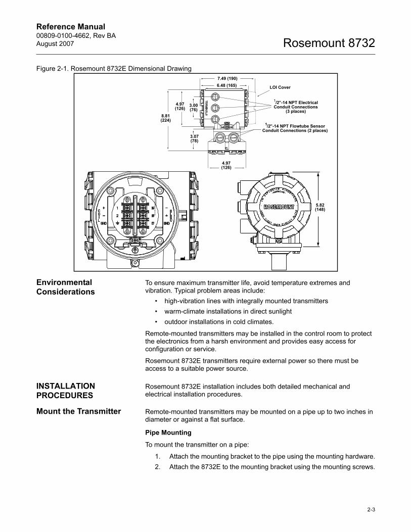
Figure 2-1. Rosemount 8732E Dimensional Drawing
Environmental Considerations
To ensure maximum transmitter life, avoid temperature extremes and vibration. Typical problem areas include:
• high-vibration lines with integrally mounted transmitters
• warm-climate installations in direct sunlight
• outdoor installations in cold climates.
Remote-mounted transmitters may be installed in the control room to protect the electronics from a harsh environment and provides easy access for configuration or service.
Rosemount 8732E transmitters require external power so there must be access to a suitable power source.
INSTALLATION PROCEDURES
Rosemount 8732E installation includes both detailed mechanical and electrical installation procedures.
Mount the Transmitter Remote-mounted transmitters may be mounted on a pipe up to two inches in diameter or against a flat surface.
Pipe Mounting
To mount the transmitter on a pipe:
1. Attach the mounting bracket to the pipe using the mounting hardware.
2. Attach the 8732E to the mounting bracket using the mounting screws.
5.82(148)
6.48 (165)
7.49 (190)
LOI Cover
4.97 (126)
8.81 (224)
3.00(76)
3.07 (78)
4.97 (126)
1/2”-14 NPT Electrical
Conduit Connections (3 places)
1/2”-14 NPT Flowtube Sensor
Conduit Connections (2 places)
2-3
Reference Manual00809-0100-4662, Rev BA
August 2007Rosemount 8732
Surface Mounting
To surface mount the transmitter:
1. Attach the 8732E to the mounting location using the mounting screws.
Identify Options and Configurations
The standard application of the 8732E includes a 4-20 mA output and control of the flowtube sensor coils. Other applications may require one or more of the following configurations or options:
• Multidrop Communication (locks the 4-20 mA output to 4 mA)
• HART Communication
• Pulse Output
• Digital Output
• Digital Input
Additional options may apply. Be sure to identify those options and configurations that apply to your situation, and keep a list of them nearby for consideration during the installation and configuration procedures.
Hardware Switches The 8732E electronics board is equipped with three user-selectable hardware switches. These switches set the Failure Alarm Mode, Internal/External Analog Power, Transmitter Security, and Internal/External Pulse Power. The standard configuration for these switches when shipped from the factory are as follows:
NOTEFor electronics with intrinsically safe (I.S. Output) approvals, analog and pulse power must be provided externally. The electronics do not include these hardware switches.
Definitions of these switches and their functions are provided below. If you determine that the settings must be changed, see below.
Failure Alarm Mode
If the 8732E experiences a catastrophic failure in the electronics, the current output can be driven high (23.25 mA) or low (3.75 mA). The switch is set in the HIGH (23.25 mA) position when it is shipped from the factory.
Internal/External Analog Power
The 8732E 4–20 mA loop may be powered internally or by an external power supply. The internal/external power supply switch determines the source of the 4–20 mA loop power.
Transmitters are shipped from the factory with the switch set in the INTERNAL position.
Failure Alarm Mode: HIGH
Internal/External Analog Power: INTERNAL
Transmitter Security: OFF
Internal/External Pulse Power INTERNAL
2-4
Reference Manual 00809-0100-4662, Rev BA
August 2007 Rosemount 8732
The external power option is required for multidrop configurations. A 10–30 V DC external supply is required and the 4-20 mA power switch must be set to the EXTERNAL position. For further information on 4–20 mA external power, see “Connect 4–20 mA Loop External Power Source” on page 2-10.
Transmitter Security
The security switch on the 8732E allows the user to lock out any configuration changes attempted on the transmitter. No changes to the configuration are allowed when the switch is in the ON position. The flow rate indication and totalizer functions remain active at all times.
With the switch in the ON position, you may still access and review any of the operating parameters and scroll through the available choices, but no actual data changes are allowed. Transmitter security is set in the OFF position when shipped from the factory.
Internal/External Pulse Power
The 8732E pulse loop may be powered internally or by an external power supply. The internal/external power supply switch determines the source of the pulse loop power.
Transmitters are shipped from the factory with the switch set in the INTERNAL position.
A 5-28 V DC external supply is required when the pulse power switch is set to the EXTERNAL position. For further information on the pulse external power, see “Connect Pulse Output Power Source” on page 2-11.
Changing Hardware Switch Settings
In most cases, it is not necessary to change the setting of the hardware switches. If you need to change the switch settings, complete the steps below:
NOTEThe hardware switches are located on the top side of the electronics board and changing their settings requires opening the electronics housing. If possible, carry out these procedures away from the plant environment in order to protect the electronics.
1. Disconnect power to the transmitter.
2. Remove electronics cover.
3. Remove LOI if applicable.
4. Identify the location of each switch (see Figure 2-2).
5. Change the setting of the desired switches with a small screwdriver.
6. Replace the electronics cover.
2-5
Reference Manual00809-0100-4662, Rev BA
August 2007Rosemount 8732
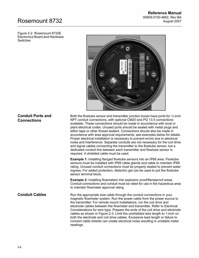
Figure 2-2. Rosemount 8732E Electronics Board and Hardware Switches
Conduit Ports and Connections
Both the flowtube sensor and transmitter junction boxes have ports for 1/2-inch NPT conduit connections, with optional CM20 and PG 13.5 connections available. These connections should be made in accordance with local or plant electrical codes. Unused ports should be sealed with metal plugs and teflon tape or other thread sealant. Connections should also be made in accordance with area approval requirements, see examples below for details. Proper electrical installation is necessary to prevent errors due to electrical noise and interference. Separate conduits are not necessary for the coil drive and signal cables connecting the transmitter to the flowtube sensor, but a dedicated conduit line between each transmitter and flowtube sensor is required. A shielded cable must be used.
Example 1: Installing flanged flowtube sensors into an IP68 area. Flowtube sensors must be installed with IP68 cable glands and cable to maintain IP68 rating. Unused conduit connections must be properly sealed to prevent water ingress. For added protection, dielectric gel can be used to pot the flowtube sensor terminal block.
Example 2: Installing flowmeters into explosion proof/flameproof areas. Conduit connections and conduit must be rated for use in the hazardous area to maintain flowmeter approval rating.
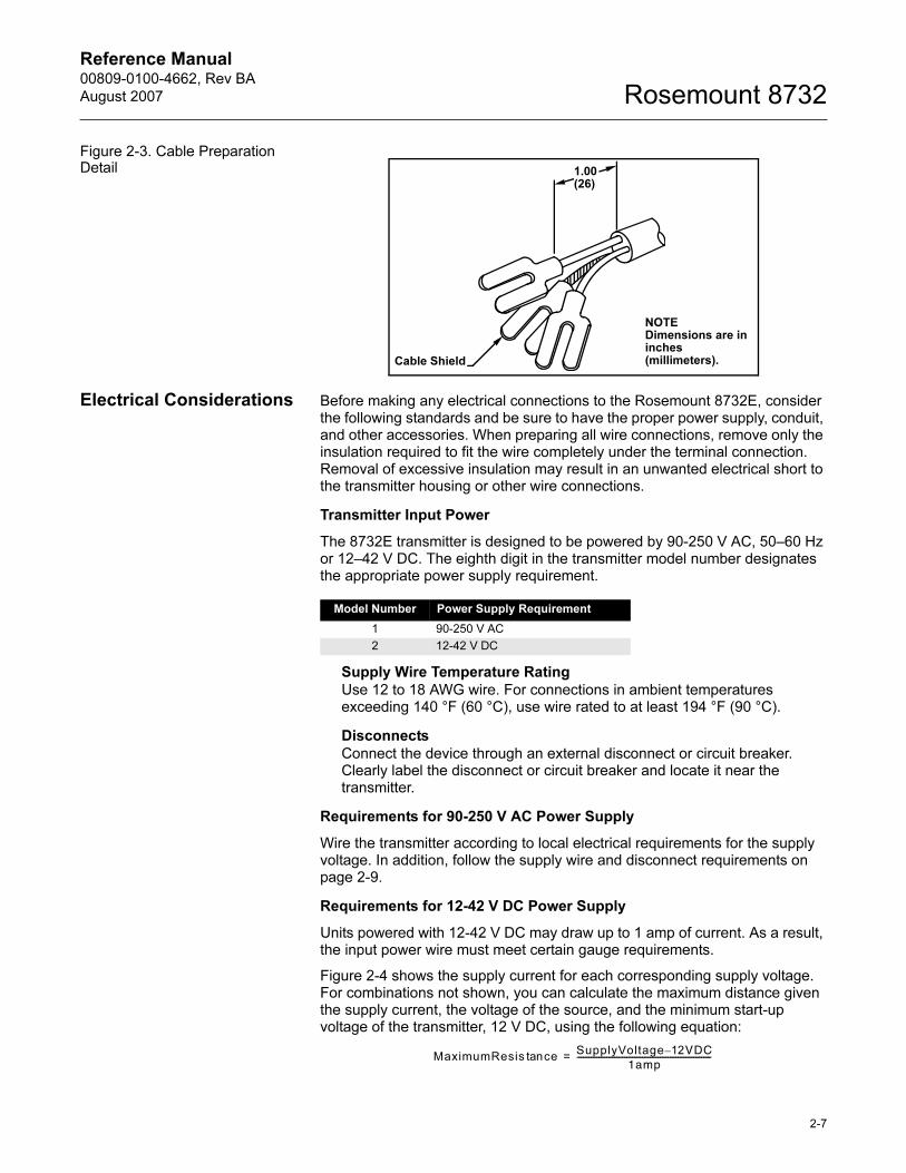
Conduit Cables Run the appropriate size cable through the conduit connections in your magnetic flowmeter system. Run the power cable from the power source to the transmitter. For remote mount installations, run the coil drive and electrode cables between the flowmeter and transmitter. Refer to Electrical Considerations for wire type. Prepare the ends of the coil drive and electrode cables as shown in Figure 2-3. Limit the unshielded wire length to 1-inch on both the electrode and coil drive cables. Excessive lead length or failure to connect cable shields can create electrical noise resulting in unstable meter readings.
2-6
Reference Manual 00809-0100-4662, Rev BA
August 2007 Rosemount 8732
Figure 2-3. Cable Preparation Detail
Electrical Considerations Before making any electrical connections to the Rosemount 8732E, consider the following standards and be sure to have the proper power supply, conduit, and other accessories. When preparing all wire connections, remove only the insulation required to fit the wire completely under the terminal connection. Removal of excessive insulation may result in an unwanted electrical short to the transmitter housing or other wire connections.
Transmitter Input Power
The 8732E transmitter is designed to be powered by 90-250 V AC, 50–60 Hz or 12–42 V DC. The eighth digit in the transmitter model number designates the appropriate power supply requirement.
Supply Wire Temperature RatingUse 12 to 18 AWG wire. For connections in ambient temperatures exceeding 140 °F (60 °C), use wire rated to at least 194 °F (90 °C).
DisconnectsConnect the device through an external disconnect or circuit breaker. Clearly label the disconnect or circuit breaker and locate it near the transmitter.
Requirements for 90-250 V AC Power Supply
Wire the transmitter according to local electrical requirements for the supply voltage. In addition, follow the supply wire and disconnect requirements on page 2-9.
Requirements for 12-42 V DC Power Supply
Units powered with 12-42 V DC may draw up to 1 amp of current. As a result, the input power wire must meet certain gauge requirements.
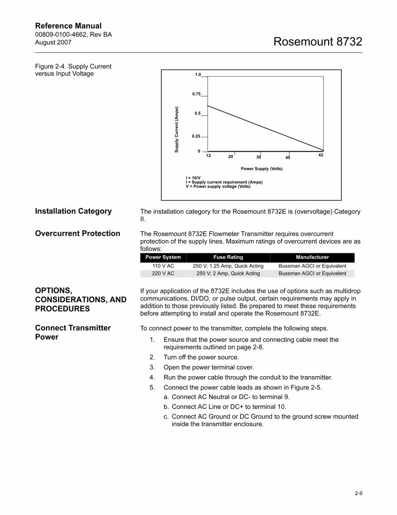
Figure 2-4 shows the supply current for each corresponding supply voltage. For combinations not shown, you can calculate the maximum distance given the supply current, the voltage of the source, and the minimum start-up voltage of the transmitter, 12 V DC, using the following equation:
NOTEDimensions are in inches (millimeters).
1.00(26)
Cable Shield
Model Number Power Supply Requirement
1 90-250 V AC
2 12-42 V DC
MaximumResis cetanSupplyVoltage 12– VDC
1amp--------------------------------------------------------------------=
2-7
Reference Manual00809-0100-4662, Rev BA
August 2007Rosemount 8732
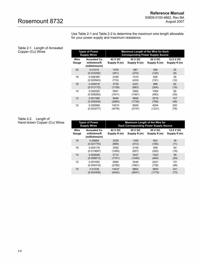
Use Table 2-1 and Table 2-2 to determine the maximum wire length allowable for your power supply and maximum resistance.
Table 2-1. Length of Annealed Copper (Cu) Wires
Table 2-2. Length of Hand-drawn Copper (Cu) Wires
Types of Power
Supply Wires
Maximum Length of the Wire for Each
Corresponding Power Supply Source
Wire
Gauge
Annealed Cu
milliohms/ft
(milliohms/m)
42 V DC
Supply ft (m)
30 V DC
Supply ft (m)
20 V DC
Supply ft (m)
12.5 V DC
Supply ft (m)
20 0.01015
(0.033292)
1478
(451)
887
(270)
394
(120)
25
(8)
18 0.006385
(0.020943)
2349
(716)
1410
(430)
626
(191)
39
(12)
16 0.004016
(0.013172)
3735
(1139)
2241
(683)
996
(304)
62
(19)
14 0.002525
(0.008282)
5941
(1811)
3564
(1087)
1584
(483)
99
(30)
12 0.001588
(0.005209)
9446
(2880)
5668
(1728)
2519
(768)
157
(48)
10 0.000999
(0.003277)
15015
(4578)
9009
(2747)
4004
(1221)
250
(76)
Types of Power
Supply Wires
Maximum Length of the Wire for
Each Corresponding Power Supply Source
Wire
Gauge
Annealed Cu
milliohms/ft
(milliohms/m)
42 V DC
Supply ft (m)
30 V DC
Supply ft (m)
20 V DC
Supply ft (m)
12.5 V DC
Supply ft (m)
18 0.00664
(0.021779)
2259
(689)
1355
(413)
602
(184)
38
(11)
16 0.004176
(0.013697)
3592
(1095)
2155
(657)
958
(292)
60
(18)
14 0.002626
(0.008613)
5712
(1741)
3427
(1045)
1523
(464)
95
(29)
12 0.001652
(0.005419)
9080
(2768)
5448
(1661)
2421
(738)
151
(46)
10 0.01039
(0.003408)
14437
(4402)
8662
(2641)
3850
(1174)
241
(73)
2-8
Reference Manual 00809-0100-4662, Rev BA
August 2007 Rosemount 8732
Figure 2-4. Supply Current versus Input Voltage
Installation Category The installation category for the Rosemount 8732E is (overvoltage) Category II.
Overcurrent Protection The Rosemount 8732E Flowmeter Transmitter requires overcurrent protection of the supply lines. Maximum ratings of overcurrent devices are as follows:
OPTIONS, CONSIDERATIONS, AND PROCEDURES
If your application of the 8732E includes the use of options such as multidrop communications, DI/DO, or pulse output, certain requirements may apply in addition to those previously listed. Be prepared to meet these requirements before attempting to install and operate the Rosemount 8732E.
Connect Transmitter Power
To connect power to the transmitter, complete the following steps.
1. Ensure that the power source and connecting cable meet the requirements outlined on page 2-8.
2. Turn off the power source.
3. Open the power terminal cover.
4. Run the power cable through the conduit to the transmitter.
5. Connect the power cable leads as shown in Figure 2-5.
a. Connect AC Neutral or DC- to terminal 9.
b. Connect AC Line or DC+ to terminal 10.
c. Connect AC Ground or DC Ground to the ground screw mounted inside the transmitter enclosure.
Power Supply (Volts)
12 4220 30 40
I = 10/VI = Supply current requirement (Amps)V = Power supply voltage (Volts)
Su
pp
ly C
urr
en
t (A
mp
s)
1.0
0.75
0.5
0.25
0
Power System Fuse Rating Manufacturer
110 V AC 250 V; 1.25 Amp, Quick Acting Bussman AGCI or Equivalent
220 V AC 250 V; 2 Amp, Quick Acting Bussman AGCI or Equivalent
2-9
Reference Manual00809-0100-4662, Rev BA
August 2007Rosemount 8732
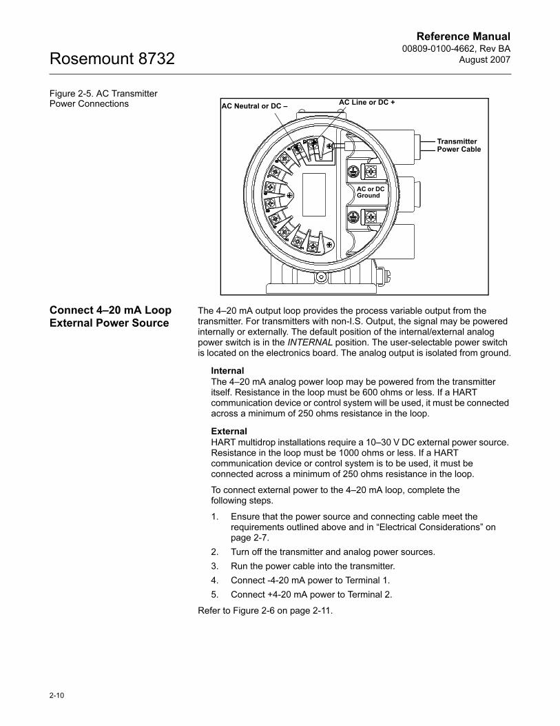
Figure 2-5. AC Transmitter Power Connections
Connect 4–20 mA Loop External Power Source
The 4–20 mA output loop provides the process variable output from the transmitter. For transmitters with non-I.S. Output, the signal may be powered internally or externally. The default position of the internal/external analog power switch is in the INTERNAL position. The user-selectable power switch is located on the electronics board. The analog output is isolated from ground.
InternalThe 4–20 mA analog power loop may be powered from the transmitter itself. Resistance in the loop must be 600 ohms or less. If a HART communication device or control system will be used, it must be connected across a minimum of 250 ohms resistance in the loop.
ExternalHART multidrop installations require a 10–30 V DC external power source. Resistance in the loop must be 1000 ohms or less. If a HART communication device or control system is to be used, it must be connected across a minimum of 250 ohms resistance in the loop.
To connect external power to the 4–20 mA loop, complete the following steps.
1. Ensure that the power source and connecting cable meet the requirements outlined above and in “Electrical Considerations” on page 2-7.
2. Turn off the transmitter and analog power sources.
3. Run the power cable into the transmitter.
4. Connect -4-20 mA power to Terminal 1.
5. Connect +4-20 mA power to Terminal 2.
Refer to Figure 2-6 on page 2-11.
AC Line or DC +
Transmitter Power Cable
AC Neutral or DC –
AC or DC Ground
2-10
Reference Manual 00809-0100-4662, Rev BA
August 2007 Rosemount 8732
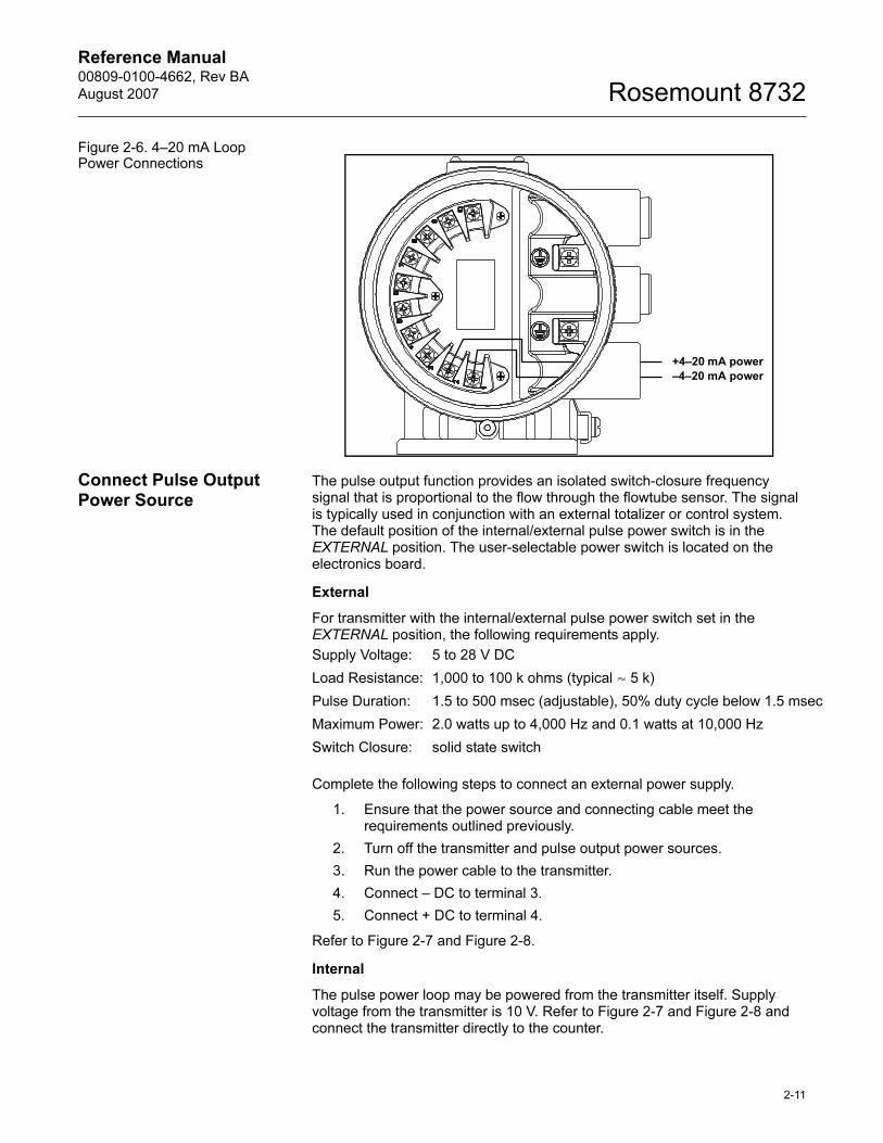
Figure 2-6. 4–20 mA Loop Power Connections
Connect Pulse Output Power Source
The pulse output function provides an isolated switch-closure frequency signal that is proportional to the flow through the flowtube sensor. The signal is typically used in conjunction with an external totalizer or control system. The default position of the internal/external pulse power switch is in the EXTERNAL position. The user-selectable power switch is located on the electronics board.
External
For transmitter with the internal/external pulse power switch set in the EXTERNAL position, the following requirements apply.
Complete the following steps to connect an external power supply.
1. Ensure that the power source and connecting cable meet the requirements outlined previously.
2. Turn off the transmitter and pulse output power sources.
3. Run the power cable to the transmitter.
4. Connect – DC to terminal 3.
5. Connect + DC to terminal 4.
Refer to Figure 2-7 and Figure 2-8.
Internal
The pulse power loop may be powered from the transmitter itself. Supply voltage from the transmitter is 10 V. Refer to Figure 2-7 and Figure 2-8 and connect the transmitter directly to the counter.
–4–20 mA power
+4–20 mA power
Supply Voltage: 5 to 28 V DC
Load Resistance: 1,000 to 100 k ohms (typical � 5 k)
Pulse Duration: 1.5 to 500 msec (adjustable), 50% duty cycle below 1.5 msec
Maximum Power: 2.0 watts up to 4,000 Hz and 0.1 watts at 10,000 Hz
Switch Closure: solid state switch
2-11
Reference Manual00809-0100-4662, Rev BA
August 2007Rosemount 8732
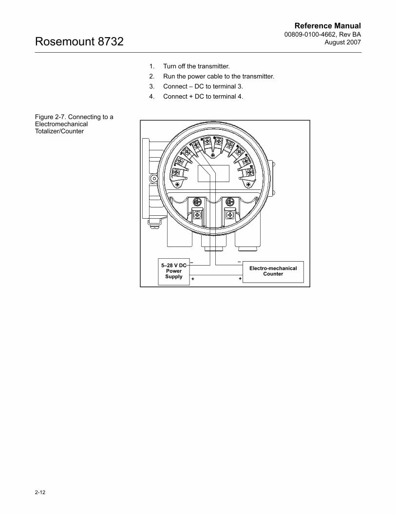
1. Turn off the transmitter.
2. Run the power cable to the transmitter.
3. Connect – DC to terminal 3.
4. Connect + DC to terminal 4.
Figure 2-7. Connecting to a Electromechanical Totalizer/Counter
Electro-mechanical Counter
5–28 V DC Power Supply +
––
+
2-12
Reference Manual 00809-0100-4662, Rev BA
August 2007 Rosemount 8732
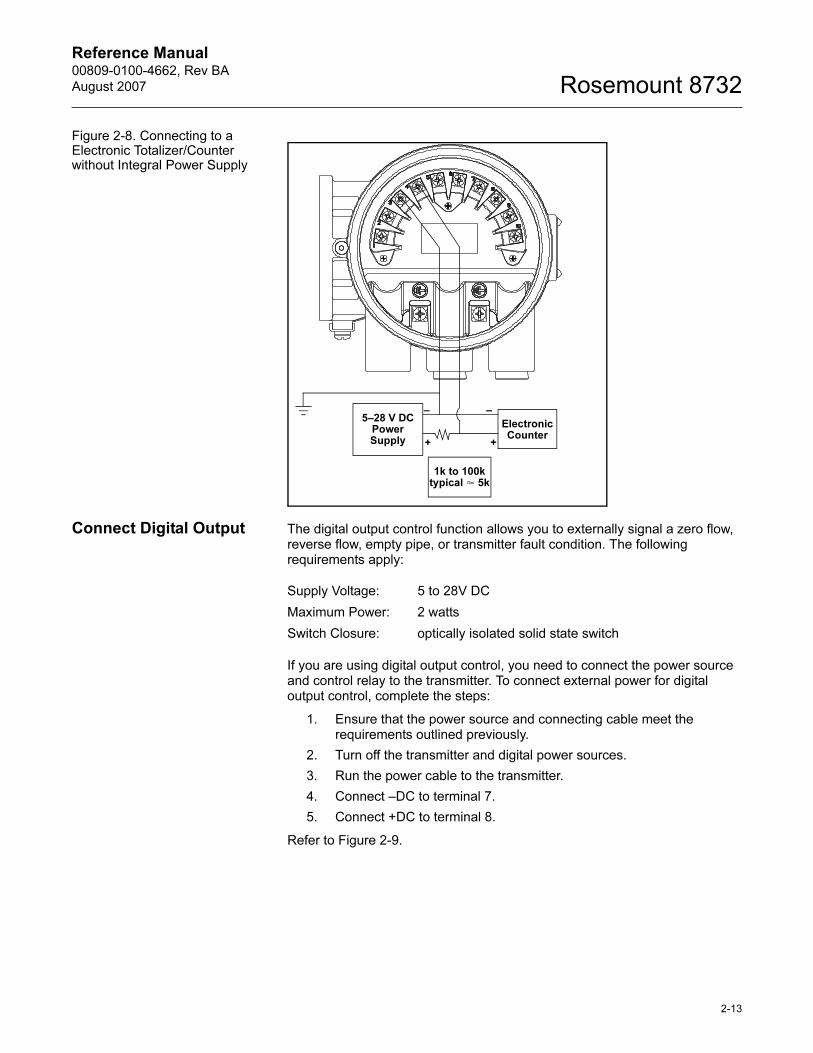
Figure 2-8. Connecting to a Electronic Totalizer/Counter without Integral Power Supply
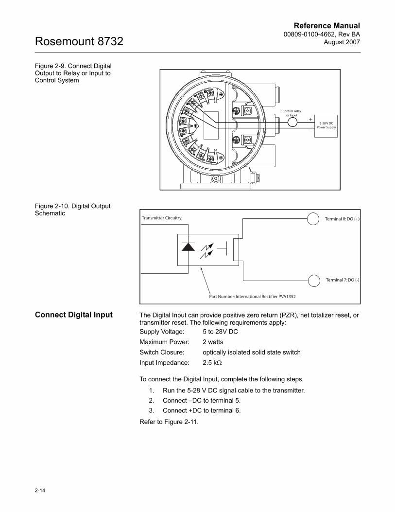
Connect Digital Output The digital output control function allows you to externally signal a zero flow, reverse flow, empty pipe, or transmitter fault condition. The following requirements apply:
If you are using digital output control, you need to connect the power source and control relay to the transmitter. To connect external power for digital output control, complete the steps:
1. Ensure that the power source and connecting cable meet the requirements outlined previously.
2. Turn off the transmitter and digital power sources.
3. Run the power cable to the transmitter.
4. Connect –DC to terminal 7.
5. Connect +DC to terminal 8.
Refer to Figure 2-9.
Electronic Counter
5–28 V DC Power Supply
–
++
–
1k to 100k typical � 5k
Supply Voltage: 5 to 28V DC
Maximum Power: 2 watts
Switch Closure: optically isolated solid state switch
2-13
Reference Manual00809-0100-4662, Rev BA
August 2007Rosemount 8732
Figure 2-9. Connect Digital Output to Relay or Input to Control System
Figure 2-10. Digital Output Schematic
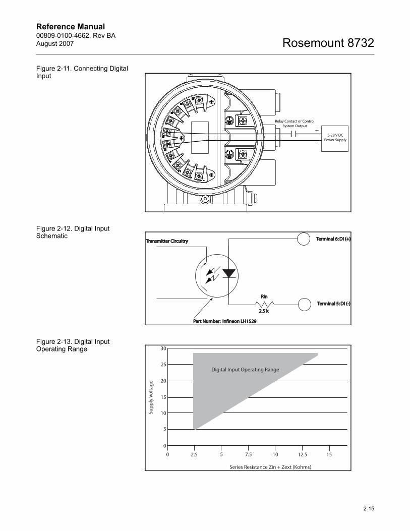
Connect Digital Input The Digital Input can provide positive zero return (PZR), net totalizer reset, or transmitter reset. The following requirements apply:
To connect the Digital Input, complete the following steps.
1. Run the 5-28 V DC signal cable to the transmitter.
2. Connect –DC to terminal 5.
3. Connect +DC to terminal 6.
Refer to Figure 2-11.
Control Relayor Input
5-28 V DCPower Supply
Terminal 8: DO (+)
Terminal 7: DO (-)
Part Number: International Rectifier PVA1352
Transmitter Circuitry
Supply Voltage: 5 to 28V DC
Maximum Power: 2 watts
Switch Closure: optically isolated solid state switch
Input Impedance: 2.5 kΩ
2-14
Reference Manual 00809-0100-4662, Rev BA
August 2007 Rosemount 8732
Figure 2-11. Connecting Digital Input
Figure 2-12. Digital Input Schematic
Figure 2-13. Digital Input Operating Range
Relay Contact or ControlSystem Output
5-28 V DCPower Supply
Terminal 6: DI (+)Terminal 6: DI (+)
Terminal 5: DI (-)Terminal 5: DI (-)
Part Number: Infineon LH1529Part Number: Infineon LH1529
2.5 k2.5 k
RinRin
Transmitter CircuitryTransmitter Circuitry
0
5
10
15
20
25
30
2.5 5 7.5 10 12.5 150
Digital Input Operating Range
Sup
ply
Vo
ltag
e
Series Resistance Zin + Zext (Kohms)
2-15
Reference Manual00809-0100-4662, Rev BA
August 2007Rosemount 8732
2-16
FLOWTUBE SENSOR CONNECTIONS
This section covers the steps required to physically install the transmitter including wiring and calibration.
Rosemount Flowtube Sensors
To connect the transmitter to a non-Rosemount flowtube sensor, refer to the appropriate wiring diagram in Appendix D: Wiring Diagrams. The calibration procedure listed is not required for use with Rosemount flowtube sensors.
Transmitter to Flowtube Sensor Wiring
Flanged and wafer flowtube sensors have two conduit ports as shown in Figures 4-13, 4-14, 4-15, and 4-16. Either one may be used for both the coil drive and electrode cables. Use the stainless steel plug that is provided to seal the unused conduit port.
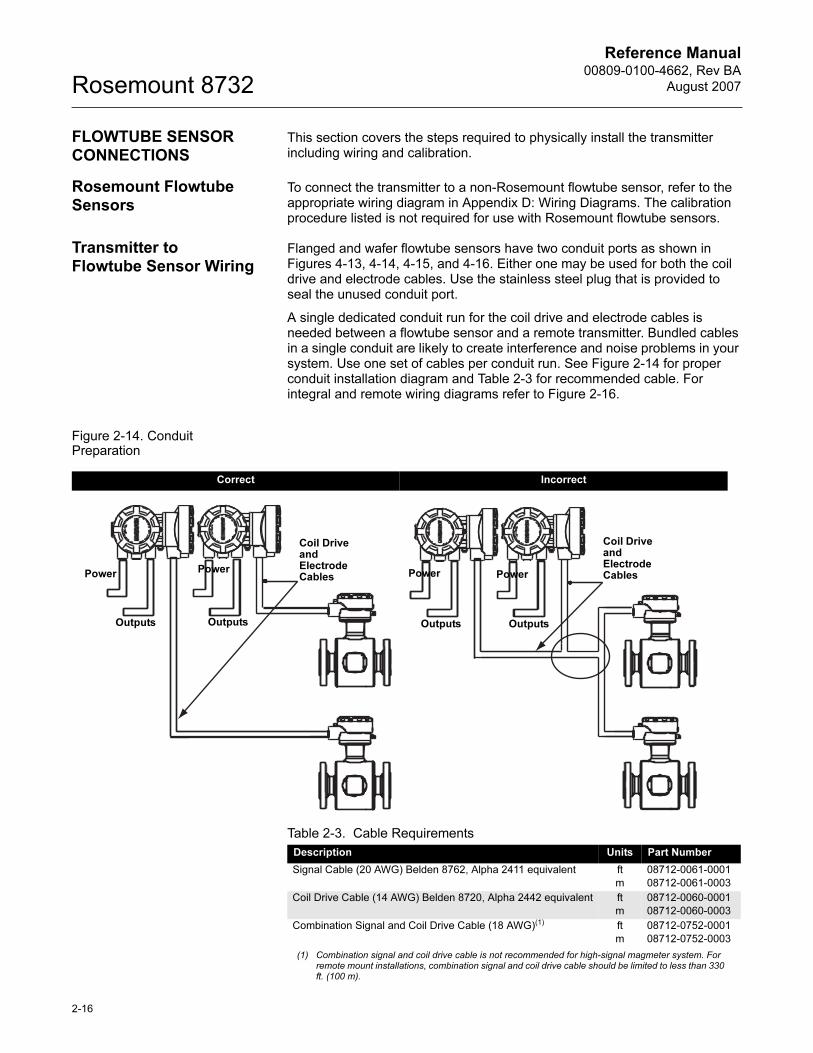
A single dedicated conduit run for the coil drive and electrode cables is needed between a flowtube sensor and a remote transmitter. Bundled cables in a single conduit are likely to create interference and noise problems in your system. Use one set of cables per conduit run. See Figure 2-14 for proper conduit installation diagram and Table 2-3 for recommended cable. For integral and remote wiring diagrams refer to Figure 2-16.
Figure 2-14. Conduit Preparation
Correct Incorrect
Coil Drive andElectrode CablesPower Power
OutputsOutputs
Coil Drive andElectrode CablesPower
Outputs
Power
Outputs
Table 2-3. Cable Requirements
Description Units Part Number
Signal Cable (20 AWG) Belden 8762, Alpha 2411 equivalent ft
m
08712-0061-0001
08712-0061-0003
Coil Drive Cable (14 AWG) Belden 8720, Alpha 2442 equivalent ft
m
08712-0060-0001
08712-0060-0003
Combination Signal and Coil Drive Cable (18 AWG)(1)
(1) Combination signal and coil drive cable is not recommended for high-signal magmeter system. For remote mount installations, combination signal and coil drive cable should be limited to less than 330 ft. (100 m).
ft
m
08712-0752-0001
08712-0752-0003
Reference Manual 00809-0100-4662, Rev BA
August 2007 Rosemount 8732
Rosemount recommends using the combination signal and coil drive for N5, E5 approved flowtube sensors for optimum performance.
Remote transmitter installations require equal lengths of signal and coil drive cables. Integrally mounted transmitters are factory wired and do not require interconnecting cables.
Lengths from 5 to 1,000 feet (1.5 to 300 meters) may be specified, and will be shipped with the flowtube sensor.
Conduit Cables Run the appropriate size cable through the conduit connections in your magnetic flowmeter system. Run the power cable from the power source to the transmitter. Run the coil drive and electrode cables between the flowmeter and transmitter.
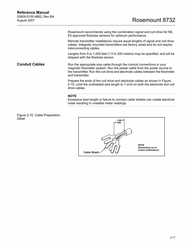
Prepare the ends of the coil drive and electrode cables as shown in Figure 2-15. Limit the unshielded wire length to 1-inch on both the electrode and coil drive cables.
NOTEExcessive lead length or failure to connect cable shields can create electrical noise resulting in unstable meter readings.
Figure 2-15. Cable Preparation Detail
1.00(26)
NOTEDimensions are in inches (millimeters).
Cable Shield
2-17
Reference Manual00809-0100-4662, Rev BA
August 2007Rosemount 8732
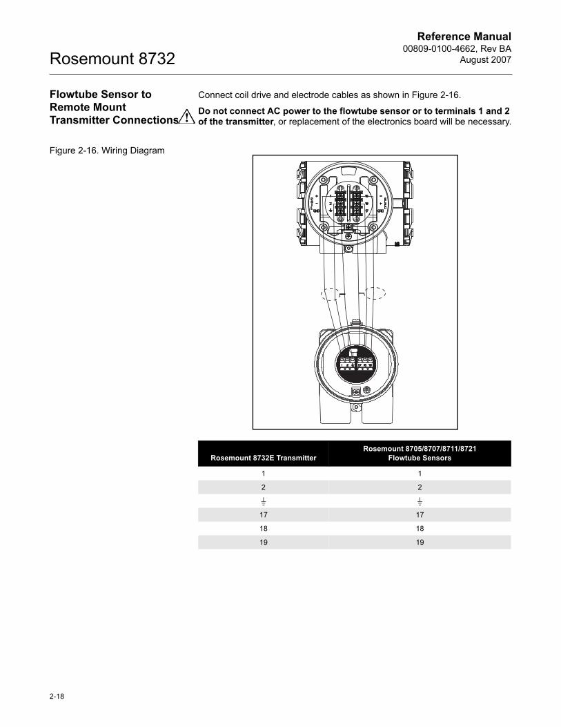
Flowtube Sensor to Remote Mount Transmitter Connections
Connect coil drive and electrode cables as shown in Figure 2-16.
Do not connect AC power to the flowtube sensor or to terminals 1 and 2 of the transmitter, or replacement of the electronics board will be necessary.
Figure 2-16. Wiring Diagram
Rosemount 8732E Transmitter
Rosemount 8705/8707/8711/8721
Flowtube Sensors
1 1
2 2
17 17
18 18
19 19
2-18
Reference Manual 00809-0100-4662, Rev BA
August 2007 Rosemount 8732
Section 3 Configuration
Introduction . . . . . . . . . . . . . . . . . . . . . . . . . . . . . . . . . . . . . page 3-1
Local Operator Interface . . . . . . . . . . . . . . . . . . . . . . . . . . page 3-1
Basic Features . . . . . . . . . . . . . . . . . . . . . . . . . . . . . . . . . . page 3-1
LOI Examples . . . . . . . . . . . . . . . . . . . . . . . . . . . . . . . . . . . page 3-2
Diagnostic Messages . . . . . . . . . . . . . . . . . . . . . . . . . . . . . page 3-5
Process Variables . . . . . . . . . . . . . . . . . . . . . . . . . . . . . . . . page 3-5
Basic Setup . . . . . . . . . . . . . . . . . . . . . . . . . . . . . . . . . . . . . page 3-7
INTRODUCTION This section covers basic operation, software functionality, and configuration procedures for the Rosemount 8732 Magnetic Flowmeter Transmitter. For information on connecting another manufacturer’s flowtube, refer to Appendix D: Wiring Diagrams.
The Rosemount 8732 features a full range of software functions for configuration of output from the transmitter. Software functions are accessed through the LOI, AMS, a Handheld Communicator, or a control system. Configuration variables may be changed at any time and specific instructions are provided through on-screen instructions.
LOCAL OPERATOR INTERFACE
The optional Local Operator Interface (LOI) provides an operator communications center for the 8732. By using the LOI, the operator can access any transmitter function for changing configuration parameter settings, checking totalized values, or other functions. The LOI is integral to the transmitter electronics.
BASIC FEATURES The basic features of the LOI include 4 navigational arrow keys that are used to access the menu structure. See Figure 3-1
Table 3-1. Parameters
Basic Set-up Parameters Page
Review page 3-5
Process Variables page 3-5
Basic Setup page 3-7
Flow Units page 3-7
Range Values page 3-10
PV Sensor/Flowtube Calibration Number page 3-11
Totalizer Setup page 3-6
www.rosemount.com
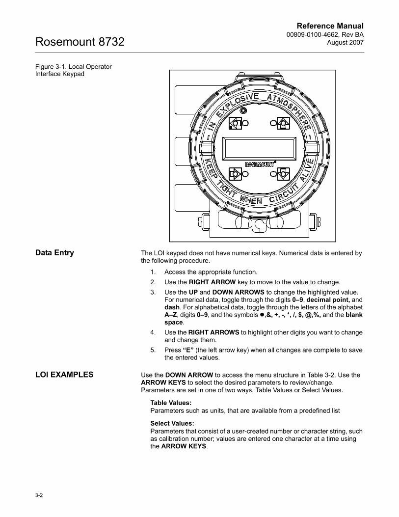
Reference Manual00809-0100-4662, Rev BA
August 2007Rosemount 8732
Figure 3-1. Local Operator Interface Keypad
Data Entry The LOI keypad does not have numerical keys. Numerical data is entered by the following procedure.
1. Access the appropriate function.
2. Use the RIGHT ARROW key to move to the value to change.
3. Use the UP and DOWN ARROWS to change the highlighted value. For numerical data, toggle through the digits 0–9, decimal point, and dash. For alphabetical data, toggle through the letters of the alphabet A–Z, digits 0–9, and the symbols �,&, +, -, *, /, $, @,%, and the blank space.
4. Use the RIGHT ARROWS to highlight other digits you want to change and change them.
5. Press “E” (the left arrow key) when all changes are complete to save the entered values.
LOI EXAMPLES Use the DOWN ARROW to access the menu structure in Table 3-2. Use the ARROW KEYS to select the desired parameters to review/change. Parameters are set in one of two ways, Table Values or Select Values.
Table Values:Parameters such as units, that are available from a predefined list
Select Values:Parameters that consist of a user-created number or character string, such as calibration number; values are entered one character at a time using the ARROW KEYS.
3-2
Reference Manual 00809-0100-4662, Rev BA
August 2007 Rosemount 8732
Table Value Example Setting the TUBE SIZE:
1. Press the DOWN arrow to access the menu.
2. Select line size from the Basic set-up menu.
3. Press the UP or DOWN arrow to increase/decrease (incrementally) the tube size to the next value.
4. When you reach the desired size, press “E” (the left arrow).
5. Set the loop to manual if necessary, and press “E” again.
After a moment, the LCD will display the new tube size and the maximum flow rate.
Select Value Example Changing the ANALOG OUTPUT RANGE:
1. Press the DOWN arrow to access the menu.
2. Using the arrow keys, select PV URV from the Basic Setup menu.
3. Press RIGHT arrow key to position the cursor.
4. Press UP or DOWN to set the number.
5. Repeat steps 2 and 3 until desired number is displayed.
6. Press “E”.
After a moment, the LCD will display the new analog output range.
3-3
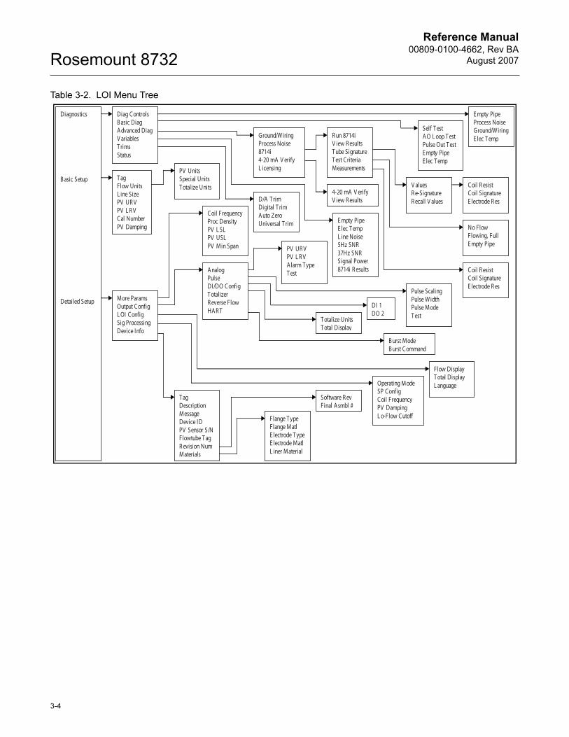
Reference Manual00809-0100-4662, Rev BA
August 2007Rosemount 8732
Table 3-2. LOI Menu Tree
Diag Controls B asic Diag A dvanced Diag V ariablesT rims Status
E mpty Pipe Process Noise Ground/WiringE lec T emp
Self T est A O L oop T est Pulse Out T est E mpty Pipe E lec T emp
Ground/WiringProcess Noise 8714i4-20 mA V erify L icensing
R un 8714i V iew R esults T ube SignatureT est Criteria Measurements
V aluesR e-Signature R ecall V alues
Coil R esist Coil Signature E lectrode R es
No Flow Flowing, Full E mpty Pipe
Coil R esist Coil Signature E lectrode R es
E mpty Pipe E lec T emp L ine Noise 5Hz SNR 37Hz SNR Signal Power 8714i R esults
D/A T rim Digital T rim A uto Zero Universal T rim
4-20 mA V erify V iew R esults
T agFlow Units L ine Size PV UR V PV L R V Cal Number PV Damping
Coil FrequencyProc Density PV L SL PV USL PV Min Span
A nalogPulse DI/DO Config T otalizer R everse Flow HA R T
PV UR V PV L R V A larm T ype T est
Pulse Scaling Pulse Width Pulse Mode T est
DI 1 DO 2
T otalize Units T otal Display
B urst Mode B urst Command
Flange T ype Flange Matl E lectrode T ypeE lectrode Matl L iner Material
Software R ev Final A smbl #
T agDescriptionMessage Device ID PV Sensor S/N Flowtube T ag R evision Num Materials
Operating Mode SP Config Coil Frequency PV Damping L o-Flow Cutoff
Flow Display T otal Display L anguage
More Params Output Config L OI Config Sig Processing Device Info
PV Units Special Units T otalize Units
Diagnostics
B asic Setup
Detailed Setup
3-4
Reference Manual 00809-0100-4662, Rev BA
August 2007 Rosemount 8732
DIAGNOSTIC MESSAGES
The following error messages may appear on the LOI screen. See Table 6-1 on page 6-3 for potential causes and corrective actions for these errors:
• Electronics Failure
• Coil open circuit
• Digital trim failure
• Auto zero failure
• Auto trim failure
• Flowrate > sensor limit
• Analog out of range
• PZR activated
• Electronics Temp Fail
• Pulse out of range
• Empty pipe
• Reverse flow
• Electronics temp out of range
The following error messages may appear on the LOI screen. See Table 6-2 on page 6-4 for potential causes and corrective actions for these errors:
• High Process Noise
• Grounding/Wiring Fault
• 4-20 mA Loop Verification Failed
• 8714i Failed
Review The 8732 includes a capability that enables you to review the configuration variable settings.
The flowmeter configuration parameters set at the factory should be reviewed to ensure accuracy and compatibility with your particular application of the flowmeter.
NOTEIf you are using the LOI to review variables, each variable must be accessed as if you were going to change its setting. The value displayed on the LOI screen is the configured value of the variable.
PROCESS VARIABLES The process variables measure flow in several ways that reflect your needs and the configuration of your flowmeter. When commissioning a flowmeter, review each process variable, its function and output, and take corrective action if necessary before using the flowmeter in a process application
Process Variable (PV) – The actual measured flow rate in the line. Use the Process Variable Units function to select the units for your application.
Percent of Range – The process variable as a percentage of the Analog Output range, provides an indication where the current flow of the meter is within the configured range of the flowmeter. For example, the Analog Output range may be defined as 0 gal/min to 20 gal/min. If the measured flow is 10 gal/min, the percent of range is 50 percent.
Fast Keys 1, 5
Fast Keys 1, 1
3-5
Reference Manual00809-0100-4662, Rev BA
August 2007Rosemount 8732
Analog Output – The analog output variable provides the analog value for the flow rate. The analog output refers to the industry standard output in the 4–20 mA range. The analog output and 4-20 mA loop can be verified using the Analog Feedback diagnostic capability internal to the transmitter (See “4-20 mA Loop Verification” on page C-8).
Totalizer Setup – Provides a reading of the total flow of the flowmeter since the totalizer was last reset. The totalizer value should be zero during commissioning on the bench, and the units should reflect the volume units of the flow rate. If the totalizer value is not zero, it may need to be reset. This function also allows for configuration of the totalizer parameters.
Pulse Output – Provides the actual pulse reading from the flow transmitter.
PV - Primary Variable The Primary Variable shows the current measured flow rate. This value determines the analog output from the transmitter.
PV -% Range The PV% Range shows where in the flow range the current flow value is as a percentage of the configured span.
PV - Analog Output The PV Analog Output displays the mA output of the transmitter corresponding to the measured flow rate.
Totalizer Setup The Totalizer Setup menu allows for the viewing and configuration of the totalizer parameters.
Totalizer Units
Totalizer units allow for the configuration of the units that the totalized value will be displayed as. These units are independent of the flow units.
Measured Gross Total
Measured gross total provides the output reading of the totalizer. This value is the amount of process fluid that has passed through the flowmeter since the totalizer was last reset.
NOTETo reset the measured gross total value, one of the following parameters must be changed: line size, calibration number, or flow units.
Measured Net Total
Measured net total provides the output reading of the totalizer. This value is the amount of process fluid that has passed through the flowmeter since the totalizer was last reset. When reverse flow is enabled, the net total represents the difference between the total flow in the forward direction less the total flow in the reverse direction.
Fast Keys 1, 1, 1
Fast Keys 1, 1, 2
Fast Keys 1, 1, 3
Fast Keys 1, 1, 4
Fast Keys 1, 1, 4, 1
Fast Keys 1, 1, 4, 2
Fast Keys 1, 1, 4, 3
3-6
Reference Manual 00809-0100-4662, Rev BA
August 2007 Rosemount 8732
Measured Reverse Total
Measured reverse total provides the output reading of the totalizer. This value is the amount of process fluid that has passed through the flowmeter in the reverse direction since the totalizer was last reset. This value is only totalized when reverse flow is enabled.
Start Totalizer
Start totalizer starts the totalizer counting from its current value.
Stop Totalizer
Stop totalizer interrupts the totalizer count until it is restarted again. This feature is often used during pipe cleaning or other maintenance operations.
Reset Totalizer
Reset totalizer resets the net totalizer value to zero. The totalizer must be stopped before resetting.
NOTEThe totalizer value is saved in the Non-Volatile memory of the electronics every three seconds. Should power to the transmitter be interrupted, the totalizer value will start at the last saved value when power is re-applied.
Pulse Output The Pulse Output displays the current value of the pulse signal.
BASIC SETUP The basic configuration functions of the Rosemount 8732 must be set for all applications of the transmitter in a magnetic flowmeter system. If your application requires the advanced functionality features of the Rosemount 8732, see Section 4 of this manual.
Tag Tag is the quickest and shortest way of identifying and distinguishing between transmitters. Transmitters can be tagged according to the requirements of your application. The tag may be up to eight characters long.
Flow Units Flow Units set the output units for the Primary Variable which controls the analog output of the transmitter.
Primary Variable Units
The Primary Variable Units specifies the format in which the flow rate will be displayed. Units should be selected to meet your particular metering needs.
Fast Keys 1, 1, 4, 4
Fast Keys 1, 1, 4, 5
Fast Keys 1, 1, 4, 6
Fast Keys 1, 1, 4, 7
Fast Keys 1, 1, 5
Fast Keys 1, 3
Fast Keys 1, 3, 1
Fast Keys 1, 3, 2
Fast Keys 1, 3, 2, 1
3-7
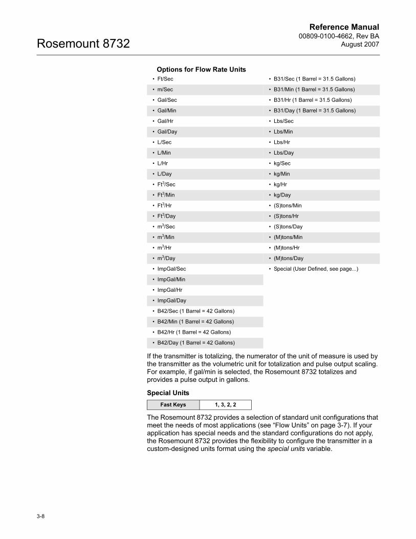
Reference Manual00809-0100-4662, Rev BA
August 2007Rosemount 8732
Options for Flow Rate Units
If the transmitter is totalizing, the numerator of the unit of measure is used by the transmitter as the volumetric unit for totalization and pulse output scaling. For example, if gal/min is selected, the Rosemount 8732 totalizes and provides a pulse output in gallons.
Special Units
The Rosemount 8732 provides a selection of standard unit configurations that meet the needs of most applications (see “Flow Units” on page 3-7). If your application has special needs and the standard configurations do not apply, the Rosemount 8732 provides the flexibility to configure the transmitter in a custom-designed units format using the special units variable.
• Ft/Sec • B31/Sec (1 Barrel = 31.5 Gallons)
• m/Sec • B31/Min (1 Barrel = 31.5 Gallons)
• Gal/Sec • B31/Hr (1 Barrel = 31.5 Gallons)
• Gal/Min • B31/Day (1 Barrel = 31.5 Gallons)
• Gal/Hr • Lbs/Sec
• Gal/Day • Lbs/Min
• L/Sec • Lbs/Hr
• L/Min • Lbs/Day
• L/Hr • kg/Sec
• L/Day • kg/Min
• Ft3/Sec • kg/Hr
• Ft3/Min • kg/Day
• Ft3/Hr • (S)tons/Min
• Ft3/Day • (S)tons/Hr
• m3/Sec • (S)tons/Day
• m3/Min • (M)tons/Min
• m3/Hr • (M)tons/Hr
• m3/Day • (M)tons/Day
• ImpGal/Sec • Special (User Defined, see page...)
• ImpGal/Min
• ImpGal/Hr
• ImpGal/Day
• B42/Sec (1 Barrel = 42 Gallons)
• B42/Min (1 Barrel = 42 Gallons)
• B42/Hr (1 Barrel = 42 Gallons)
• B42/Day (1 Barrel = 42 Gallons)
Fast Keys 1, 3, 2, 2
3-8
Reference Manual 00809-0100-4662, Rev BA
August 2007 Rosemount 8732
Special Volume Unit
Special volume unit enables you to display the volume unit format to which you have converted the base volume units. For example, if the special units are abc/min, the special volume variable is abc. The volume units variable is also used in totalizing the special units flow.
Base Volume Unit
Base volume unit is the unit from which the conversion is being made. Set this variable to the appropriate option.
Conversion Number
The special units conversion number is used to convert base units to special units. For a straight conversion of volume units from one to another, the conversion number is the number of base units in the new unit. For example, if you are converting from gallons to barrels and there are 31 gallons in a barrel, the conversion factor is 31.
Base Time Unit
Base time unit provides the time unit from which to calculate the special units. For example, if your special units is a volume per minute, select minutes.
Special Flow Rate Unit
Special flow rate unit is a format variable that provides a record of the units to which you are converting. The Handheld Communicator and Rosemount 8732 will display a special units designator as the units format for your primary variable. The actual special units setting you define will not appear. Four characters are available to store the new units designation.
Example
To display flow in barrels per hour, and one barrel of beer is equal to 31.0 gallons, the procedure would be:
Set the Volume Unit to BARL.Set the Base Volume Unit to Gallons.Set the Input Conversion Number to 31.Set the Time Base to Hour.Set the Rate Unit to BR/H.
Line Size The line size (tube size) must be set to match the actual flowtube connected to the transmitter. The size must be specified in inches according to the available sizes listed below. If a value is entered from a control system or Handheld Communicator that does not match one of these figures, the value will go to the next highest option.
Fast Keys 1, 3, 2, 2, 1
Fast Keys 1, 3, 2, 2, 2
Fast Keys 1, 3, 2, 2, 3
Fast Keys 1, 3, 2, 2, 4
Fast Keys 1, 3, 2, 2, 5
Fast Keys 1, 3, 3
3-9
Reference Manual00809-0100-4662, Rev BA
August 2007Rosemount 8732
The line size (inches) options are as follows:
PV URV (Upper Range Value)
The upper range value (URV), or analog output range, is preset to 30 ft/s at the factory. The units that appear will be the same as those selected under the units parameter.
The URV (20 mA point) can be set for both forward or reverse flow rate. Flow in the forward direction is represented by positive values and flow in the reverse direction is represented by negative values. The URV can be any value from –39.3 ft/s to +39.3 ft/s (-12 m/s to +12 m/s), as long as it is at least 1 ft/s from the lower range value (4 mA point). The URV can be set to a value less than the lower range value. This will cause the transmitter analog output to operate in reverse, with the current increasing for lower (or more negative) flow rates.
NOTELine size, special units, and density must be selected prior to configuration of URV and LRV.
PV LRV (Lower Range Value)
Reset the lower range value (LRV), or analog output zero, to change the size of the range (or span) between the URV and LRV. Under normal circumstances, the LRV should be set to a value near the minimum expected flow rate to maximize resolution. The LRV must be between –39.3 ft/s to +39.3 ft/s (-12 m/s to +12 m/s).
NOTELine size, special units, and density must be selected prior to configuration of URV and LRV.
Example
If the URV is greater than the LRV, the analog output becomes 3.9 mA when the flow rate falls below the selected 4 mA point.
The minimum allowable span between the URV and LRV is 1 ft/s. Do not set the LRV within 1 ft/s of the 20 mA point. For example, if the URV is set to 15.67 ft/s and if the desired URV is greater than the LRV, then the highest allowable analog zero setting would be 14.67 ft/s. If the desired URV is less than the LRV, then the lowest allowable LRV would be 16.67 ft/s.
0.1, 0.15, 0.25, 0.30, 0.50, 0.75, 1, 1.5, 2, 2.5, 3, 4, 6, 8, 10, 12, 14, 16, 18, 20, 24, 28, 30, 32, 36, 40, 42, 44, 48, 54, 56, 60, 64, 72, 80
Fast Keys 1, 3, 4
Fast Keys 1, 3, 5
3-10
Reference Manual 00809-0100-4662, Rev BA
August 2007 Rosemount 8732
Calibration Number The tube calibration number is a 16-digit number used to identify flowtubes calibrated at the Rosemount factory. The calibration number is also printed inside the flowtube terminal block or on the flowtube name plate. The number provides detailed calibration information to the Rosemount 8732. To function properly within accuracy specifications, the number stored in the transmitter must match the calibration number on the flowtube exactly.
NOTEFlowtubes from manufacturers other than Rosemount Inc. can also be calibrated at the Rosemount factory. Check the tube for Rosemount calibration tags to determine if a 16-digit tube calibration number exists for your flowtube.
NOTEBe sure the calibration number reflects a calibration to a Rosemount reference transmitter. If the calibration number was generated by a means other than a certified Rosemount flow lab, accuracy of the system may be compromised.
If your flowtube is not a Rosemount flowtube and was not calibrated at the Rosemount factory, please review “Calibration Number” on this page.
If your flowtube is imprinted with an eight-digit number or a k-factor, check in the flowtube wiring compartment for the sixteen-digit calibration number. If there is no serial number, contact the factory for a proper conversion.
PV Damping Adjustable between 0.0 and 256 seconds
PV Damping allows selection of a response time, in seconds, to a step change in flow rate. It is most often used to smooth fluctuations in output.
Fast Keys 1, 3, 6
Fast Keys 1, 3, 7
3-11

Reference Manual00809-0100-4662, Rev BA
August 2007Rosemount 8732
3-12
Reference Manual 00809-0100-4662, Rev BA
August 2007 Rosemount 8732
Section 4 Operation
Introduction . . . . . . . . . . . . . . . . . . . . . . . . . . . . . . . . . . . . . page 4-1
Diagnostics . . . . . . . . . . . . . . . . . . . . . . . . . . . . . . . . . . . . . page 4-1
Basic Diagnostics . . . . . . . . . . . . . . . . . . . . . . . . . . . . . . . . page 4-2
Advanced Diagnostics . . . . . . . . . . . . . . . . . . . . . . . . . . . . page 4-4
Advanced Configuration . . . . . . . . . . . . . . . . . . . . . . . . . . page 4-13
Detailed Setup . . . . . . . . . . . . . . . . . . . . . . . . . . . . . . . . . . . page 4-13
INTRODUCTION This section contains information for advanced configuration parameters and diagnostics.
The software configuration settings for the Rosemount 8732 can be accessed through a HART-based communicator, Local Operator Interface (LOI), or through a control system. The software functions for the HART Communicator are described in detail in this section of the manual. It provides an overview and summary of communicator functions. For more complete instructions, see the communicator manual. Before operating the Rosemount 8732 in an actual installation, you should review all of the factory set configuration data to ensure that they reflect the current application.
DIAGNOSTICS Diagnostics are used to verify that the transmitter is functioning properly, to assist in troubleshooting, to identify potential causes of error messages, and to verify the health of the transmitter and flowtube. Diagnostic tests can be initiated through the use of a HART-based communications device, the Local Operator Interface, or through the control system.
Rosemount offers several different diagnostic suites providing various functionality.
Standard diagnostics included with every Rosemount 8732 transmitter are Empty Pipe detection, Electronics Temperature monitoring, Coil Fault detection, and various loop and transmitter tests.
Advanced diagnostics suite option one (DA1 option) contains advanced diagnostics for High Process Noise detection and Grounding and Wiring fault detection.
Advanced diagnostics suite option two (DA2 option) contains advanced diagnostics for the 8714i Internal Meter Calibration Verification. This diagnostic is used to verify the accuracy and performance of the magnetic flow meter installation.
Diagnostic Controls The diagnostic controls menu provides a centralized location for enabling or disabling each of the diagnostics that are available. Note that for some diagnostics to be available, a diagnostics suite package is required.
HART Comm. 1, 2
HART Comm. 1, 2, 1
www.rosemount.com
Reference Manual00809-0100-4662, Rev BA
August 2007Rosemount 8732
Empty Pipe
Turn the empty pipe diagnostic on or off as required by the application. For more details on the empty pipe diagnostic, see Appendix C: Diagnostics.
High Process Noise
Turn the high process noise diagnostic on or off as required by the application. For more details on the high process noise diagnostic, see Appendix C: Diagnostics.
Grounding / Wiring
Turn the grounding / wiring diagnostic on or off as required by the application. For more details on the grounding / wiring diagnostic, see Appendix C: Diagnostics.
Electronics Temperature
Turn the electronics temperature diagnostic on or off as required by the application. For more details on the electronics temperature diagnostic, see Appendix C: Diagnostics.
Basic Diagnostics The basic diagnostics menu contains all of the standard diagnostics and tests that are available in the 8732E transmitter.
Self Test
The transmitter test initiates a series of diagnostic tests that are not performed continuously during normal operation. It performs the following tests:
• Display Test
• RAM Test
• PROM Test
During the entire test, all outputs respond to flow signal. The test requires about ten seconds to complete.
AO Loop Test
The AO Loop test allows you to drive the transmitter output to a desired electrical current output on terminals 1 and 2. The user then has the ability to independently measure the actual loop current against the desired level set be the transmitter. On the LOI, the test will end after five minutes if the transmitter is not returned to normal operation manually.
4 mA
Fix the analog loop current at 4 mA.
20 mA
Fix the analog loop current at 20 mA.
HART Comm. 1, 2, 1, 1
HART Comm. 1, 2, 1, 2
HART Comm. 1, 2, 1, 3
HART Comm. 1, 2, 1, 4
HART Comm. 1, 2, 2
HART Comm. 1, 2, 2, 1
HART Comm. 1, 2, 2, 2
HART Comm. 1, 2, 2, 2, 1
HART Comm. 1, 2, 2, 2, 2
4-2
Reference Manual 00809-0100-4662, Rev BA
August 2007 Rosemount 8732
Simulate Alarm
Send the analog output into an alarm mA value. Actual mA value depends on the alarm configuration.
• Rosemount Standard High Alarm – 22.6 mA
• Rosemount Standard Low Alarm – 3.75 mA
• Namur Compliant High Alarm – 22.6 mA
• Namur Compliant Low Alarm – 3.5 mA
Other
Fix the analog loop current to some other mA value between 3.5 mA and 23.0 mA.
End
This command cancels the analog loop test and returns the analog output back into normal operating mode.
Pulse Output Loop Test
The Pulse Output Loop Test allows you to drive the frequency output at terminals 3 and 4 to a desired value. The user then has the ability to compare the pulse output value measured by auxiliary equipment to the desired pulse output level set by the transmitter. On the LOI the test will end after five minutes if the transmitter is not returned to normal operation manually.
Select Value
Set the value of the pulse output for the test to a value between 1 pulse/day to 10,000 Hz.
End
This command cancels the pulse output loop test and returns the pulse output back into normal operating mode.
Empty Pipe Limits
Empty Pipe allows you to view the current value and configure the diagnostic parameters. For more detail on this parameter see Appendix C: Diagnostics.
Empty Pipe Value
Read the current Empty Pipe Value. This number is a unitless number and is calculated based on multiple installation and process variables. For more detail on this parameter see Appendix C: Diagnostics.
HART Comm. 1, 2, 2, 2, 3
HART Comm. 1, 2, 2, 2, 4
HART Comm. 1, 2, 2, 2, 5
HART Comm. 1, 2, 2, 3
HART Comm. 1, 2, 2, 3, 1
HART Comm. 1, 2, 2, 3, 2
HART Comm. 1, 2, 2, 4
HART Comm. 1, 2, 2, 4, 1
4-3
Reference Manual00809-0100-4662, Rev BA
August 2007Rosemount 8732
Empty Pipe Trigger Level
Limits: 3 to 2000
Configure the threshold limit that the empty pipe value must exceed before the diagnostic alert activates. Default from the factory is set to 100. For more detail on this parameter see Appendix C: Diagnostics.
Empty Pipe Counts
Limits: 5 to 50
Configure the number of consecutive times that the empty pipe value must exceed the empty pipe trigger level before the diagnostic alert activates. Counts are taken at 1.5 second intervals. Default from the factory is set to 5. For more detail on this parameter see Appendix C: Diagnostics.
Electronics Temperature
Electronics Temperature allows you to view the current value for the electronics temperature.
Advanced Diagnostics The advanced diagnostics menu contains information on all of the additional diagnostics and tests that are available in the 8732 transmitter if one of the diagnostics suite packages was ordered.
Rosemount offers two advanced diagnostic suites. Functionality under this menu will depend on which of these suites are ordered.
Advanced diagnostics suite option one (DA1 option) contains advanced diagnostics for High Process Noise detection and Grounding and Wiring fault detection.
Advanced diagnostics suite option two (DA2 option) contains advanced diagnostics for the 8714i Internal Meter Calibration Verification. This diagnostic is used to verify the accuracy and performance of the magnetic flow meter installation.
8714i Calibration Verification™
This diagnostic allows you to test and verify that the flowtube, transmitter, or both are working within specifications. For more details on this diagnostic, see Appendix C: Diagnostics.
Run 8714i Verification
Run the meter verification test to check the transmitter, flowtube, or entire installation.
Full Meter Verification
Run the internal meter verification to validate the entire installation, flowtube and transmitter at the same time.
HART Comm. 1, 2, 2, 4, 2
HART Comm. 1, 2, 2, 4, 3
HART Comm. 1, 2, 2, 5
HART Comm. 1, 2, 3
HART Comm. 1, 2, 3, 1
HART Comm. 1, 2, 3, 1, 1
HART Comm. 1, 2, 3, 1, 1, 1
4-4
Reference Manual 00809-0100-4662, Rev BA
August 2007 Rosemount 8732
Transmitter Only
Run the internal meter verification to validate the transmitter only.
Flowtube Only
Run the internal meter verification to validate the flowtube only.
8714i Results
Review the results of the most recently performed 8714i Internal Meter Verification test. Information in this section details the measurements taken and if the meter passed the verification test. For more details on these results and what they mean, see Appendix C: Diagnostics.
Test Condition
Displays the conditions that the 8714i Calibration Verification test was performed under. For more details on this parameter see Appendix C: Diagnostics.
Test Criteria
Displays the criteria that the 8714i Calibration Verification test was performed against. For more details on this parameter see Appendix C: Diagnostics.
8714i Test Result
Displays the results of the 8714i Calibration Verification test as pass or fail. For more details on this parameter see Appendix C: Diagnostics.
Simulated Velocity
Displays the test velocity used to verify transmitter calibration. For more details on this parameter see Appendix C: Diagnostics.
Actual Velocity
Displays the velocity measured by the transmitter during the transmitter calibration verification test. For more details on this parameter see Appendix C: Diagnostics.
Velocity Deviation
Displays the deviation of the transmitter calibration verification test. For more details on this parameter see Appendix C: Diagnostics.
Transmitter Calibration Test Result
Displays the result of the transmitter calibration verification test as pass or fail. For more details on this parameter see Appendix C: Diagnostics.
HART Comm. 1, 2, 3, 1, 1, 2
HART Comm. 1, 2, 3, 1, 1, 3
HART Comm. 1, 2, 3, 1, 2
HART Comm. 1, 2, 3, 1, 2, 1
HART Comm. 1, 2, 3, 1, 2, 2
HART Comm. 1, 2, 3, 1, 2, 3
HART Comm. 1, 2, 3, 1, 2, 4
HART Comm. 1, 2, 3, 1, 2, 5
HART Comm. 1, 2, 3, 1, 2, 6
HART Comm. 1, 2, 3, 1, 2, 7
4-5
Reference Manual00809-0100-4662, Rev BA
August 2007Rosemount 8732
4-6
Flowtube Sensor Calibration Deviation
Displays the deviation of the flowtube sensor calibration verification test. For more details on this parameter see Appendix C: Diagnostics.
Flowtube Sensor Calibration Test Result
Displays the result of the flowtube sensor calibration verification test as pass or fail. For more details on this parameter see Appendix C: Diagnostics.
Coil Circuit Test Result
Displays the result of the coil circuit test as pass or fail. For more details on this parameter see Appendix C: Diagnostics.
NOTE To access these features, you must scroll to this option in the HART Field Communicator.
Electrode Circuit Test Result
Displays the result of the electrode circuit test as pass or fail. For more details on this parameter see Appendix C: Diagnostics.
NOTE To access these features, you must scroll to this option in the HART Field Communicator.
Flowtube Signature
The flowtube signature describes the flowtube characteristics to the transmitter and is an integral part of the flowtube meter verification test. From this menu you can view the current stored signature, have the transmitter take and store the flowtube signature, manually enter the signature values, and re-call the last saved good values for the flowtube signature. For more details on this parameter see Appendix C: Diagnostics.
Signature Values
Review the current values stored for the flowtube signature. For more details on this parameter see Appendix C: Diagnostics.
Re-Signature Meter
Have the transmitter measure and store the flowtube signature values. These values will then be used as the baseline for the meter verification test. Use this when connecting to older Rosemount or competitors’ flowtubes or installing the magnetic flowmeter system for the first time. For more details on this parameter see Appendix C: Diagnostics.
Recall Last Saved Values
Recalls the last saved “good” values for the flowtube signature.
HART Comm. 1, 2, 3, 1, 2, 8
HART Comm. 1, 2, 3, 1, 2, 9
HART Comm. 1, 2, 3, 1, 2, 10
HART Comm. 1, 2, 3, 1, 2, 11
HART Comm. 1, 2, 3, 1, 3
HART Comm. 1, 2, 3, 1, 3, 1
HART Comm. 1, 2, 3, 1, 3, 2
HART Comm. 1, 2, 3, 1, 3, 3
Reference Manual 00809-0100-4662, Rev BA
August 2007 Rosemount 8732
4-7
Set Pass/Fail Criteria
Set the maximum allowable deviation percentage test criteria for the 8714i Internal Meter Verification test. There are three tests that this criteria can be set for:
• Full Pipe; No Flow (Best test condition) – Default is 2%
• Full Pipe; Flowing – Default is 3%
• Empty Pipe – Default is 5%
NOTEIf the 8714i Internal Meter Verification test is done with an empty pipe, the electrode circuit will NOT be tested.
No Flow Limit
1 to 10 percent
Set the pass/fail test criteria for the 8714i Meter Verification test at Full Pipe, No Flow conditions.
Flowing Limit
1 to 10 percent
Set the pass/fail test criteria for the 8714i Meter Verification test at Full Pipe, Flowing conditions.
Empty Pipe Limit
1 to 10 percent
Set the pass/fail test criteria for the 8714i Meter Verification test at Empty Pipe conditions.
Measurements
View the measured values taken during the tube signature process. Values are shown for the Coil Resistance, Coil Signature, and Electrode Resistance.
Coil Resistance
View the measured value for the coil resistance taken during the flowtube signature process.
Coil Signature
View the measured value for the coil signature taken during the flowtube signature process.
Electrode Resistance
View the measured value for the electrode resistance taken during the flowtube signature process.
HART Comm. 1, 2, 3, 1, 4
HART Comm. 1, 2, 3, 1, 4, 1
HART Comm. 1, 2, 3, 1, 4, 2
HART Comm. 1, 2, 3, 1, 4, 3
HART Comm. 1, 2, 3, 1, 5
HART Comm. 1, 2, 3, 1, 5, 1
HART Comm. 1, 2, 3, 1, 5, 2
HART Comm. 1, 2, 3, 1, 5, 3
Reference Manual00809-0100-4662, Rev BA
August 2007Rosemount 8732
4-20 mA Verify
The 4-20 mA verify test is a diagnostic built into the transmitter to verify that the analog loop is functioning correctly. For more details on this diagnostic, see Appendix C: Diagnostics.
4-20 mA Verification
Run the 4-20 mA verification test to check the integrity of the analog loop.
4-20 mA Verify Results
View the results of the 4-20 mA Loop Verification test.
Licensing
If a diagnostic suite was not ordered initially, advanced diagnostics can be licensed in the field. Access the licensing information from this menu. For more details on licensing, see Appendix C: Diagnostics.
License Status
Determine if a diagnostics suite has been licensed, and if so, which diagnostics are available for activation.
License Key
A license key is required to activate diagnostics in the field if the diagnostic suite was not initially ordered. This menu allows for gathering of necessary data to generate a license key and also the ability to enter the license key once it has been received.
Device ID
This function displays the Device ID and Software Revision for the transmitter. Both of these pieces of information are required to generate a license key.
License Key
Allows you to enter a license key to activate a diagnostic suite.
Diagnostic Variable Values
From this menu, all of the diagnostic variable values can be reviewed. This information can be used to get more information about the transmitter, flowtube, and process, or to get more detail about an alert that may have activated.
Empty Pipe Value
Read the current value of the Empty Pipe parameter. This value will read zero if Empty Pipe is turned off.
HART Comm. 1, 2, 3, 2
HART Comm. 1, 2, 3, 2, 1
HART Comm. 1, 2, 3, 2, 2
HART Comm. 1, 2, 3, 3
HART Comm. 1, 2, 3, 3, 1
HART Comm. 1, 2, 3, 3, 2
HART Comm. 1, 2, 3, 3, 2, 1
HART Comm. 1, 2, 3, 3, 2, 2
HART Comm. 1, 2, 4
HART Comm. 1, 2, 4, 1
4-8
Reference Manual 00809-0100-4662, Rev BA
August 2007 Rosemount 8732
Electronics Temperature
Read the current value of the Electronics Temperature.
Line Noise
Read the current value of the amplitude of AC line noise measured on the transmitter’s electrode inputs. This value is used in the grounding / wiring diagnostic.
5 Hz Signal to Noise Ratio
Read the current value of the signal to noise ratio at 5 Hz. For optimum performance, a value greater than 100 is preferred. Values less than 25 will cause the High Process Noise alert to activate.
37 Hz Signal to Noise Ratio
Read the current value of the signal to noise ratio at 37.5 Hz. For optimum performance, a value greater than 100 is preferred. Values less than 25 will cause the High Process Noise alert to activate.
Signal Power
Read the current value of the velocity of the fluid through the flowtube. Higher velocities result in greater signal power.
8714i Results
Review the results of the 8714i Internal Meter Verification tests. For more details on these results and what they mean, see Appendix C: Diagnostics.
Test Condition
Displays the conditions that the 8714i Calibration Verification test was performed under. For more details on this parameter see Appendix C: Diagnostics.
Test Criteria
Displays the criteria that the 8714i Calibration Verification test was performed against. For more details on this parameter see Appendix C: Diagnostics.
8714i Test Result
Displays the results of the 8714i Calibration Verification test as pass or fail. For more details on this parameter see Appendix C: Diagnostics.
Simulated Velocity
Displays the test velocity used to verify transmitter calibration. For more details on this parameter see Appendix C: Diagnostics.
HART Comm. 1, 2, 4, 2
HART Comm. 1, 2, 4, 3
HART Comm. 1, 2, 4, 4
HART Comm. 1, 2, 4, 5
HART Comm. 1, 2, 4, 6
HART Comm. 1, 2, 4, 7
HART Comm. 1, 2, 3, 7, 1
HART Comm. 1, 2, 3, 7, 2
HART Comm. 1, 2, 3, 7, 3
HART Comm. 1, 2, 3, 7, 4
4-9
Reference Manual00809-0100-4662, Rev BA
August 2007Rosemount 8732
Actual Velocity
Displays the velocity measured by the transmitter during the transmitter calibration verification test. For more details on this parameter see Appendix C: Diagnostics.
Velocity Deviation
Displays the deviation of the transmitter calibration verification test. For more details on this parameter see Appendix C: Diagnostics.
Transmitter Verification Test Result
Displays the result of the transmitter calibration verification test as pass or fail. For more details on this parameter see Appendix C: Diagnostics.
Flowtube Sensor Verification Deviation
Displays the deviation of the flowtube sensor calibration verification test. For more details on this parameter see Appendix C: Diagnostics.
Flowtube Sensor Verification Result
Displays the result of the flowtube sensor calibration verification test as pass or fail. For more details on this parameter see Appendix C: Diagnostics.
Coil Circuit Test Result
NOTE To access these features, you must scroll to this option in the HART Field Communicator.
Displays the result of the coil circuit test as pass or fail. For more details on this parameter see Appendix C: Diagnostics.
Electrode Circuit Test Result
NOTE To access these features, you must scroll to this option in the HART Field Communicator.
Displays the result of the electrode circuit test as pass or fail. For more details on this parameter see Appendix C: Diagnostics.
Trims Trims are used to calibrate the analog loop, calibrate the transmitter, re-zero the transmitter, and calibrate the transmitter with another manufacturer’s flowtube. Proceed with caution whenever performing a trim function.
HART Comm. 1, 2, 3, 7, 5
HART Comm. 1, 2, 3, 7, 6
HART Comm. 1, 2, 3, 7, 7
HART Comm. 1, 2, 3, 7, 8
HART Comm. 1, 2, 3, 7, 9
HART Comm. 1, 2, 3, 7, 10
HART Comm. 1, 2, 3, 7, 11
HART Comm. 1, 2, 5
4-10
Reference Manual 00809-0100-4662, Rev BA
August 2007 Rosemount 8732
D/A Trim
The D/A Trim is used to calibrate the 4-20 mA analog loop output from the transmitter. For maximum accuracy, the analog output should be trimmed for your system loop. Use the following steps to complete the Output Trim function.
1. Set the loop to manual, if necessary.
2. Connect a precision ammeter in the 4–20 mA loop.
3. Initiate the Output Trim function with the LOI or Handheld Communicator.
4. Enter the 4 mA meter value when prompted to do so.
5. Enter the 20 mA meter value when prompted to do so.
6. Return the loop to automatic control, if necessary.
The 4–20 mA trim is now completed. You may repeat the 4–20 mA trim to check the results, or use the analog output test.
Scaled D/A Trim
Scaled D/A trim enables you to calibrate the flowmeter analog output using a different scale than the standard 4-20 mA output scale. Non-scaled D/A trimming (described above), is typically performed using an ammeter where calibration values are entered in units of milliamperes. Both non-scaled D/A trimming and scaled D/A trimming allow you to trim the 4-20mA output to approximately ±5% of the nominal 4mA end point and ±3% of the nominal 20mA end point. Scaled D/A trimming allows you to trim the flowmeter using a scale that may be more convenient based upon your method of measurement.
For example, it may be more convenient for you to make current measurements by direct voltage readings across the loop resistor. If your loop resistor is 500 ohms, and you want to calibrate the meter using voltage measurements made across this resistor, you could rescale your trim points from 4-20mA to 4-20mA x 500 ohm or 2-10 VDC. Once your scaled trim points have been entered as 2 and 10, you can calibrate your flowmeter by entering voltage measurements directly from the voltmeter.
Digital Trim
Digital trim is the function by which the factory calibrates the transmitter. This procedure is rarely needed by customers. It is only necessary if you suspect the Rosemount 8732E is no longer accurate. A Rosemount 8714 Calibration Standard is required to complete a digital trim. Attempting a digital trim without a Rosemount 8714 Field Calibrator may result in an inaccurate transmitter or an error message. Digital trim must be performed only with the coil drive mode set to 5 Hz and with a nominal flowtube calibration number stored in the memory.
HART Comm. 1, 2, 5, 1
HART Comm. 1, 2, 5, 2
HART Comm. 1, 2, 5, 3
4-11
Reference Manual00809-0100-4662, Rev BA
August 2007Rosemount 8732
NOTEAttempting a digital trim without a Rosemount 8714 may result in an inaccurate transmitter, or a “DIGITAL TRIM FAILURE” message may appear. If this message occurs, no values were changed in the transmitter. Simply power down the Rosemount 8732E to clear the message.
To simulate a nominal flowtube with the Rosemount 8714, you must change the following four parameters in the Rosemount 8732E:
1. Tube Calibration Number—1000015010000000
2. Units—ft/s
3. PV URV—20 mA = 30.00 ft/s
4. PV LRV—4 mA = 0 ft/s
5. Coil Drive Frequency—5 Hz
The instructions for changing the Tube Calibration Number, Units, PV URV, and PV LRV are located in “Basic Setup” on page 3-7. Instructions for changing the Coil Drive Frequency can be found on page 4-19 in this section.
Set the loop to manual, if necessary, before you begin. Complete the following steps:
1. Power down the transmitter.
2. Connect the transmitter to a Rosemount 8714 flowtube simulator.
3. Power up the transmitter with the Rosemount 8714 connected and read the flow rate. The electronics need about a 5-minute warm-up time to stabilize.
4. Set the 8714 calibrator to the 30 ft/s setting.
5. The flow rate reading after warm-up should be between 29.97 and 30.03 ft/s.
6. If the reading is within the range, return the transmitter to the original configuration parameters.
7. If the reading is not within this range, initiate a digital trim with the LOI or Handheld Communicator. The digital trim takes about 90 seconds to complete. No transmitter adjustments are required.
Auto Zero
The auto zero function initializes the transmitter for use with the 37 Hz coil drive mode only. Run this function only with the transmitter and flowtube installed in the process. The flowtube must be filled with process fluid at zero flow. Before running the auto zero function, be sure the coil drive mode is set to 37 Hz (Auto Zero will not run with the coil drive frequency set at 5 Hz).
Set the loop to manual if necessary and begin the auto zero procedure. The transmitter completes the procedure automatically in about 90 seconds. A symbol appears in the lower right-hand corner of the display to indicate that the procedure is running.
HART Comm. 1, 2, 5, 4
4-12
Reference Manual 00809-0100-4662, Rev BA
August 2007 Rosemount 8732
Universal Trim
The universal auto trim function enables the Rosemount 8732E to calibrate flowtubes that were not calibrated at the Rosemount factory. The function is activated as one step in a procedure known as in-process calibration. If your Rosemount flowtube has a 16-digit calibration number, in-process calibration is not required. If it does not, or if your flowtube is made by another manufacturer, complete the following steps for in-process calibration.
1. Determine the flow rate of the process fluid in the flowtube.
NOTEThe flow rate in the line can be determined by using another flowtube in the line, by counting the revolutions of a centrifugal pump, or by performing a bucket test to determine how fast a given volume is filled by the process fluid.
2. Complete the universal auto trim function.
3. When the routine is completed, the flowtube is ready for use.
Status Status displays a summary of the health of the transmitter. If there are any alerts or error messages that have activated, they will be listed here.
ADVANCED CONFIGURATION
In addition to the basic configuration options and the diagnostic information and controls, the 8732 has many advanced functions that can also be configured as required by the application.
DETAILED SETUP The detailed setup function provides access to other parameters within the transmitter that can be configured such as coil drive frequency, output parameters, local display configuration, and other general information about the device.
Additional Parameters The additional parameters menu provides a means to configure optional parameters within the 8732E transmitter.
Coil Drive Frequency
Coil drive frequency allows pulse-rate selection of the flowtube coils.
5 Hz
The standard coil drive frequency is 5 Hz, which is sufficient for nearly all applications.
37 Hz
If the process fluid causes a noisy or unstable output, increase the coil drive frequency to 37 Hz. If the 37 Hz mode is selected, perform the auto zero function.
Density Value
The density value is used to convert from a volumetric flow rate to a mass flow rate using the following equation:
Qm = Qv � ρ
HART Comm. 1, 2, 5, 5
HART Comm. 1, 2, 6
HART Comm. 1, 4
HART Comm. 1, 4, 1
HART Comm. 1, 4, 1, 1
HART Comm. 1, 4, 1, 2
4-13
Reference Manual00809-0100-4662, Rev BA
August 2007Rosemount 8732
Where:
Qm is the mass flow rate
Qv is the volumetric flow rate, and
ρ is the fluid density
PV Upper Sensor Limit (USL)
The PV USL is the maximum value that the 20 mA value can be set to. This is the upper measuring limit of the transmitter and flowtube.
PV Lower Sensor Limit (LSL)
The PV LSL is the minimum value that the 4 mA value can be set to. This is the lower measuring limit of the transmitter and flowtube.
PV Minimum Span
The PV minimum span is the minimum flow range that must separate the 4 mA and 20 mA set point values.
Configure Outputs The configure outputs functionality contains functionality to configure the more advanced features that control the analog, pulse, auxiliary, and totalizer outputs of the transmitter.
Analog Output
Under this function the advanced features of the analog output can be configured.
PV Upper Range Value (URV)
The upper range value (URV), or analog output range, is preset to 30 ft/s at the factory. The units that appear will be the same as those selected under the units parameter.
The URV (20 mA point) can be set for both forward or reverse flow rate. Flow in the forward direction is represented by positive values and flow in the reverse direction is represented by negative values. The URV can be any value from –39.3 ft/s to +39.3 ft/s (-12 m/s to +12 m/s), as long as it is at least 1 ft/s from the lower range value (4 mA point). The URV can be set to a value less than the lower range value. This will cause the transmitter analog output to operate in reverse, with the current increasing for lower (or more negative) flow rates.
NOTELine size, special units, and density must be selected prior to configuration of URV and LRV.
HART Comm. 1, 4, 1, 3
HART Comm. 1, 4, 1, 4
HART Comm. 1, 4, 1, 5
HART Comm. 1, 4, 2
HART Comm. 1, 4, 2, 1
HART Comm. 1, 4, 2, 1, 1
4-14
Reference Manual 00809-0100-4662, Rev BA
August 2007 Rosemount 8732
PV Lower Range Value (LRV)
Reset the lower range value (LRV), or analog output zero, to change the size of the range (or span) between the URV and LRV. Under normal circumstances, the LRV should be set to a value near the minimum expected flow rate to maximize resolution. The LRV must be between –39.3 ft/s to +39.3 ft/s (-12 m/s to +12 m/s).
NOTEThe LRV can be set to a value greater than the URV, which will cause the analog output to operate in reverse. In this mode, the analog output will increase with lower (more negative) flow rates.
Example
If the URV is greater than the LRV, the analog output becomes 3.9 mA when the flow rate falls below the selected 4 mA point. The minimum allowable span between the URV and LRV is 1 ft/s. Do not set the LRV within 1 ft/s of the 20 mA point. For example, if the URV is set to 15.67 ft/s and if the desired URV is greater than the LRV, then the highest allowable analog zero setting would be 14.67 ft/s. If the desired URV is less than the LRV, then the lowest allowable LRV would be 16.67 ft/s.
NOTELine size, special units, and density must be selected prior to configuration of URV and LRV.
PV Analog Output
The PV analog output displays the current analog output value (mA) of the transmitter corresponding to the current measured flow rate.
Analog Output Alarm Type
The analog output alarm type displays the alarm mode the 8732E is currently set for. This value is set by a switch on the electronics board. There are two available options for this setting:
• High
• Low
Loop Test
The loop test allows you to drive the transmitter output to a desired electrical current output on terminals 1 and 2. This capability allows you to check the entire current loop prior to start-up. On the LOI the test will end after five minutes if the transmitter is not returned to normal operation manually.
HART Comm. 1, 4, 2, 1, 2
HART Comm. 1, 4, 2, 1, 3
HART Comm. 1, 4, 2, 1, 4
HART Comm. 1, 4, 2, 1, 5
4-15
Reference Manual00809-0100-4662, Rev BA
August 2007Rosemount 8732
D/A Trim
The D/A Trim is used to calibrate the 4-20 mA analog loop output from the transmitter. For maximum accuracy, the analog output should be trimmed for your system loop. Use the following steps to complete the Output Trim function.
1. Set the loop to manual, if necessary.
2. Connect a precision ammeter in the 4–20 mA loop.
3. Initiate the Output Trim function with the LOI or Handheld Communicator.
4. Enter the 4 mA meter value when prompted to do so.
5. Enter the 20 mA meter value when prompted to do so.
6. Return the loop to automatic control, if necessary.
The 4–20 mA trim is now completed. You may repeat the 4–20 mA trim to check the results, or use the analog output test.
Scaled D/A Trim
Scaled D/A trim enables you to calibrate the flowmeter analog output using a different scale than the standard 4-20 mA output scale. Non-scaled D/A trimming (described above), is typically performed using an ammeter where calibration values are entered in units of milliamperes. Both non-scaled D/A trimming and scaled D/A trimming allow you to trim the 4-20mA output to approximately ±5% of the nominal 4mA end point and ±3% of the nominal 20mA end point. Scaled D/A trimming allows you to trim the flowmeter using a scale that may be more convenient based upon your method of measurement.
For example, it may be more convenient for you to make current measurements by direct voltage readings across the loop resistor. If your loop resistor is 500 ohms, and you want to calibrate the meter using voltage measurements made across this resistor, you could rescale your trim points from 4-20mA to 4-20mA x 500 ohm or 2-10 VDC. Once your scaled trim points have been entered as 2 and 10, you can calibrate your flowmeter by entering voltage measurements directly from the voltmeter.
Alarm Level
The alarm level allows you to drive the transmitter to preset values if an alarm occurs. There are two options:
• Rosemount Alarm and Saturation Values
• NAMUR-Compliant Alarm and Saturation Levels
HART Comm. 1, 4, 2, 1, 6
HART Comm. 1, 4, 2, 1, 7
HART Comm. 1, 4, 2, 1, 8
Table 4-1. Rosemount (Standard) Alarm and Saturation Values
Level 4-20 mA Saturation 4-20 mA Alarm
Low 3.9 mA ≤3.75 mA
High 20.8 mA ≥22.6 mA
4-16
Reference Manual 00809-0100-4662, Rev BA
August 2007 Rosemount 8732
Pulse Output
Under this function the pulse output of the 8732E can be configured.
Pulse Scaling
Transmitter may be commanded to supply a specified frequency between 1 pulse/ day at 39.37 ft/sec to 10,000 Hz at 1 ft/sec.
NOTELine size, special units, and density must be selected prior to configuration of the Pulse Scaling factor.
The pulse output scaling equates one transistor switch closure pulse to a selectable number of volume units. The volume unit used for scaling pulse output is taken from the numerator of the configured flow units. For example, if gal/min had been chosen when selecting the flow rate unit, the volume unit displayed would be gallons.
NOTEThe pulse output scaling is designed to operate between 0 and 10,000 Hz. The electronics will not accept a conversion factor that would result in a pulse frequency outside that range. The minimum conversion factor value is found by dividing the minimum span (in units of volume per second) by 10,000 Hz.
When selecting pulse output scaling, remember that the maximum pulse rate is 10,000 Hz. With the 110 percent overrange capability, the absolute limit is 11,000 Hz. For example, if you want the Rosemount 8732E to pulse every time 0.01 gallons pass through the flowtube, and the flow rate is 10,000 gal/min, you will exceed the 10,000 Hz full-scale limit:
The best choice for this parameter depends upon the required resolution, the number of digits in the totalizer, the extent of range required, and the maximum counter input frequency.
NOTEFor totalizing on the LOI, ten digits are available.
Table 4-2. NAMUR-Compliant Alarm and Saturation Values
Level 4-20 mA Saturation 4-20 mA Alarm
Low 3.8 mA ≤3.5 mA
High 20.5 mA ≥22.6 mA
HART Comm. 1, 4, 2, 2
HART Comm. 1, 4, 2, 2, 1
10,000 gal/min
60 sec/min( ) × 60 sec/min( )---------------------------------------------------------------------------- 16666.7 Hz=
4-17
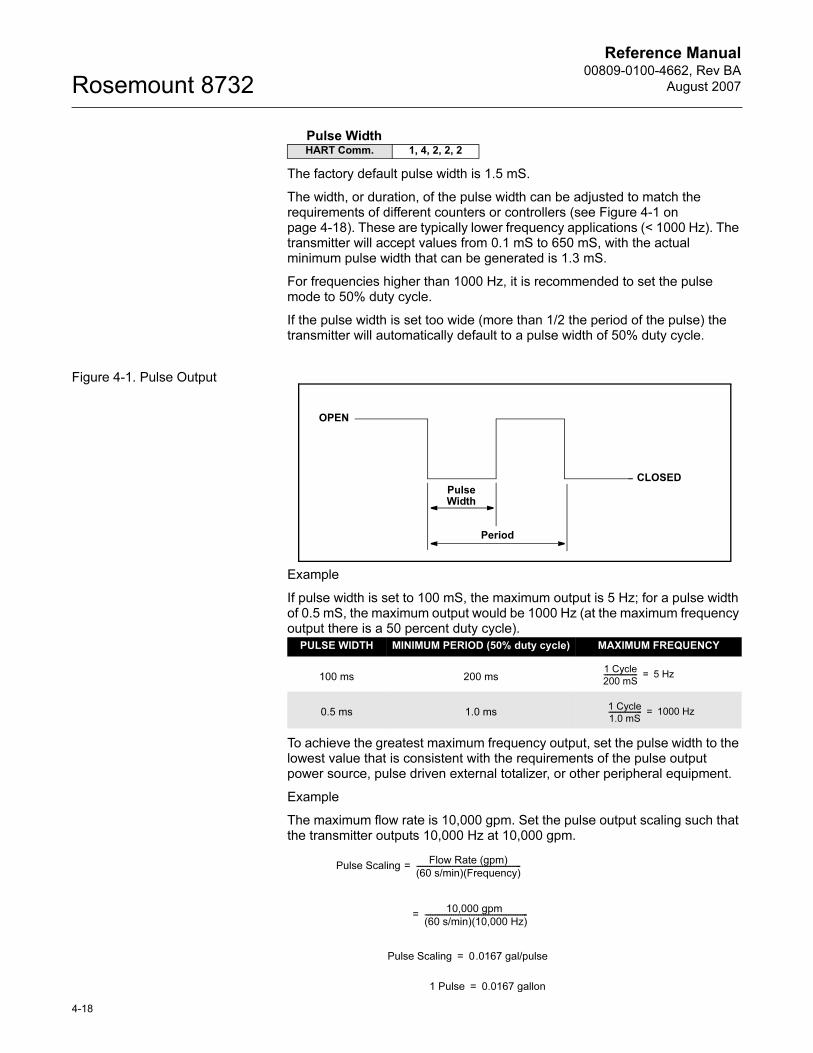
Reference Manual00809-0100-4662, Rev BA
August 2007Rosemount 8732
4-18
Pulse Width
The factory default pulse width is 1.5 mS.
The width, or duration, of the pulse width can be adjusted to match the requirements of different counters or controllers (see Figure 4-1 on page 4-18). These are typically lower frequency applications (< 1000 Hz). The transmitter will accept values from 0.1 mS to 650 mS, with the actual minimum pulse width that can be generated is 1.3 mS.
For frequencies higher than 1000 Hz, it is recommended to set the pulse mode to 50% duty cycle.
If the pulse width is set too wide (more than 1/2 the period of the pulse) the transmitter will automatically default to a pulse width of 50% duty cycle.
Figure 4-1. Pulse Output
Example
If pulse width is set to 100 mS, the maximum output is 5 Hz; for a pulse width of 0.5 mS, the maximum output would be 1000 Hz (at the maximum frequency output there is a 50 percent duty cycle).
To achieve the greatest maximum frequency output, set the pulse width to the lowest value that is consistent with the requirements of the pulse output power source, pulse driven external totalizer, or other peripheral equipment.
Example
The maximum flow rate is 10,000 gpm. Set the pulse output scaling such that the transmitter outputs 10,000 Hz at 10,000 gpm.
HART Comm. 1, 4, 2, 2, 2
PULSE WIDTH MINIMUM PERIOD (50% duty cycle) MAXIMUM FREQUENCY
100 ms 200 ms
0.5 ms 1.0 ms
Pulse Width
Period
OPEN
CLOSED
1 Cycle
200 mS-------------------- 5 Hz=
1 Cycle
1.0 mS-------------------- 1000 Hz=
Pulse Scaling Flow Rate (gpm)
(60 s/min)(Frequency)-----------------------------------------------------------=
10,000 gpm
(60 s/min)(10,000 Hz)----------------------------------------------------------=
Pulse Scaling 0.0167 gal/pulse=
1 Pulse 0.0167 gallon=
Reference Manual 00809-0100-4662, Rev BA
August 2007 Rosemount 8732
NOTEChanges to pulse width are only required when there is a minimum pulse width required for external counters, relays, etc. If frequency generated by the transmitter requires a smaller pulse width than the pulse width selected, the transmitter will automatically go to 50% duty cycle.
Example
The external counter is ranged for 350 gpm and pulse is set for one gallon. Assuming the pulse width is 0.5 ms, the maximum frequency output is 5.833 Hz.
Example
The upper range value (20 mA) is 3000 gpm. To obtain the highest resolution of the pulse output, 10,000 Hz is scaled to the full scale analog reading.
Pulse Mode
The Pulse mode configures the frequency output of the pulse. It can be set to either 50% duty cycle, or fixed. There are two options that Pulse Mode can be configured to:
• Pulse Output
• Frequency Output
To use Pulse Width settings, Pulse Mode must be set to Pulse Output.
Pulse Output Loop Test
The Pulse Output Loop Test allows you to drive the frequency output at terminals 3 and 4 to a desired value. This capability allows you to check auxiliary equipment prior to start-up. On the LOI the test will end after five minutes if the transmitter is not returned to normal operation manually.
HART Comm. 1, 4, 2, 2, 3
HART Comm. 1, 4, 2, 2, 4
FrequencyFlow Rate (gpm)
(60 s/min)(Pulse Scaling gal/pulse)----------------------------------------------------------------------------------------------=
350 gpm
(60 s/min)(1 gal/pulse)-----------------------------------------------------------=
5.833 Hz=
Pulse ScalingFlow Rate (gpm)
(60 s/min)(Frequency)-----------------------------------------------------------=
3000 gpm
(60 s/min)(10,000Hz)--------------------------------------------------------=
0.005 gal/pulse=
1 Pulse 0.005 gallon=
4-19
Reference Manual00809-0100-4662, Rev BA
August 2007Rosemount 8732
Digital Input / Digital Output
This menu is used to configure the optional digital input and digital output parameters of the 8732E transmitter. Note that this configuration option is only active if the auxiliary output suite (option code AX) was ordered.
Digital Input Channel 1
Configure the digital input value here. This controls the digital input to the transmitter on terminals 5(-) and 6(+). There are three options that the digital input can be configured for:
• Positive Zero Return (PZR)
• Totalizer Reset
Digital Output Channel 2
Configure the digital output value here. This controls the digital output from the transmitter on terminals 7(-) and 8(+). There are four options that the digital output can be configured for:
• Zero Flow
• Reverse Flow
• Transmitter Fault
• Empty Pipe
Reverse Flow
Enable or disable the transmitter’s ability to read reverse flow.
Reverse Flow allows the transmitter to read negative flow. This may occur when flow in the pipe is going the negative direction, or when either electrode wires or coil wires are reversed. This also enables the totalizer to count in the reverse direction.
Totalizer Setup
The totalizer setup menu allows for the viewing and configuration of the totalizer parameters.
Totalizer Units
Totalizer units allow for the configuration of the units that the totalized value will be displayed as. These units are independent of the flow units.
Measured Gross Total
Measured gross total provides the output reading of the totalizer. This value is the amount of process fluid that has passed through the flowmeter since the totalizer was last reset.
HART Comm. 1, 4, 2, 3
HART Comm. 1, 4, 2, 3, 1
HART Comm. 1, 4, 2, 3, 2
HART Comm. 1, 4, 2, 4
HART Comm. 1, 4, 2, 5
HART Comm. 1, 4, 2, 5, 1
HART Comm. 1, 4, 2, 5, 2
4-20
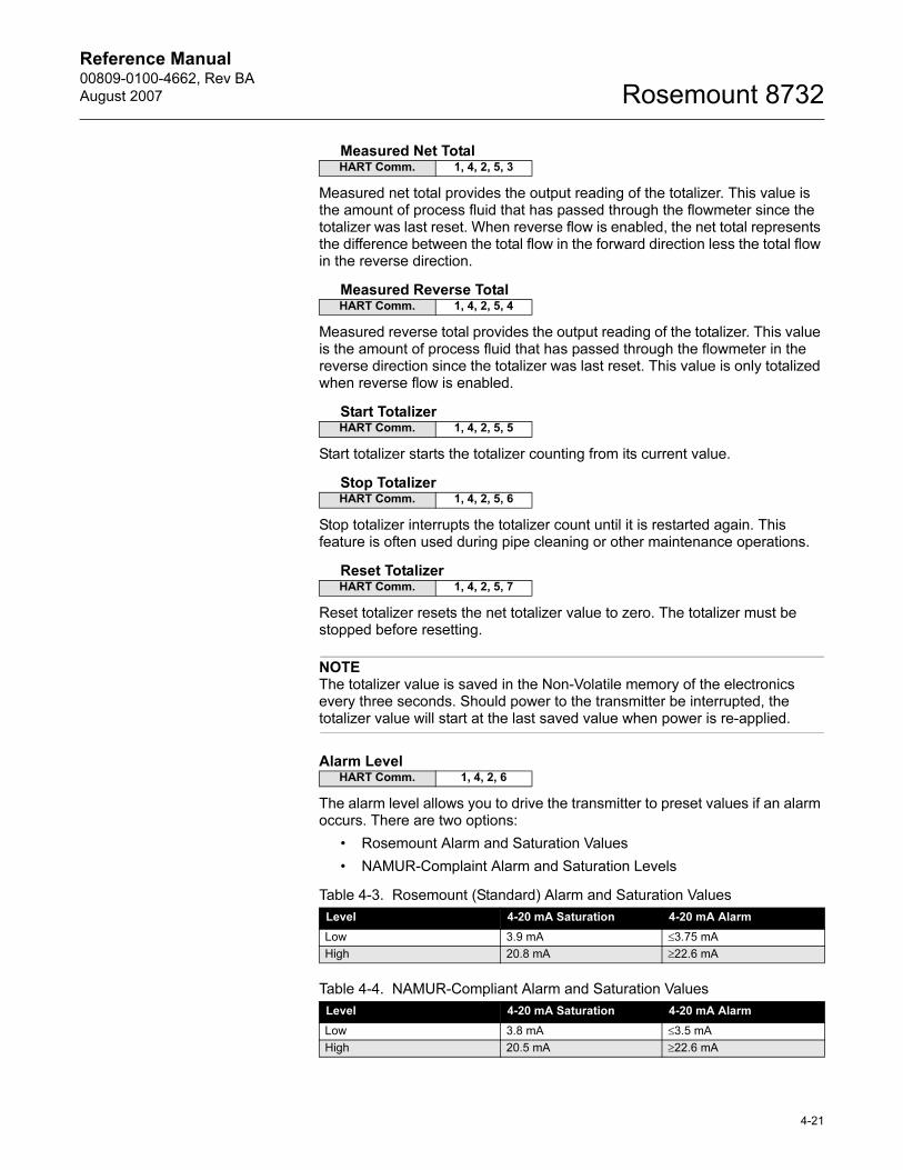
Reference Manual 00809-0100-4662, Rev BA
August 2007 Rosemount 8732
Measured Net Total
Measured net total provides the output reading of the totalizer. This value is the amount of process fluid that has passed through the flowmeter since the totalizer was last reset. When reverse flow is enabled, the net total represents the difference between the total flow in the forward direction less the total flow in the reverse direction.
Measured Reverse Total
Measured reverse total provides the output reading of the totalizer. This value is the amount of process fluid that has passed through the flowmeter in the reverse direction since the totalizer was last reset. This value is only totalized when reverse flow is enabled.
Start Totalizer
Start totalizer starts the totalizer counting from its current value.
Stop Totalizer
Stop totalizer interrupts the totalizer count until it is restarted again. This feature is often used during pipe cleaning or other maintenance operations.
Reset Totalizer
Reset totalizer resets the net totalizer value to zero. The totalizer must be stopped before resetting.
NOTEThe totalizer value is saved in the Non-Volatile memory of the electronics every three seconds. Should power to the transmitter be interrupted, the totalizer value will start at the last saved value when power is re-applied.
Alarm Level
The alarm level allows you to drive the transmitter to preset values if an alarm occurs. There are two options:
• Rosemount Alarm and Saturation Values
• NAMUR-Complaint Alarm and Saturation Levels
HART Comm. 1, 4, 2, 5, 3
HART Comm. 1, 4, 2, 5, 4
HART Comm. 1, 4, 2, 5, 5
HART Comm. 1, 4, 2, 5, 6
HART Comm. 1, 4, 2, 5, 7
HART Comm. 1, 4, 2, 6
Table 4-3. Rosemount (Standard) Alarm and Saturation Values
Level 4-20 mA Saturation 4-20 mA Alarm
Low 3.9 mA ≤3.75 mA
High 20.8 mA ≥22.6 mA
Table 4-4. NAMUR-Compliant Alarm and Saturation Values
Level 4-20 mA Saturation 4-20 mA Alarm
Low 3.8 mA ≤3.5 mA
High 20.5 mA ≥22.6 mA
4-21
Reference Manual00809-0100-4662, Rev BA
August 2007Rosemount 8732
HART Output
Multidrop configuration refers to the connection of several flowmeters to a single communications transmission line. Communication occurs digitally between a HART-based communicator or control system and the flowmeters. Multidrop mode automatically deactivates the analog output of the flowmeters. Using the HART communications protocol, up to 15 transmitters can be connected on a single twisted pair of wires or over leased phone lines. The use of a multidrop installation requires consideration of the update rate necessary from each transmitter, the combination of transmitter models, and the length of the transmission line. Multidrop installations are not recommended where intrinsic safety is a requirement. Communication with the transmitters can be accomplished with commercially available Bell 202 modems and a host implementing the HART protocol. Each transmitter is identified by a unique address (1-15) and responds to the commands defined in the HART protocol.
Variable Mapping
Variable mapping allows you to configure the variables that are mapped to the tertiary and quaternary variables.
Tertiary Variable
The tertiary variable maps the third variable of the transmitter. This variable is a HART only variable and can be read off of the HART signal with a HART enabled input card, or can be burst for use with a HART Tri-Loop to convert the HART signal to an analog output. Options available for mapping to this variable are:
• Forward Gross
• Forward Net
• Reverse Gross
• Electronics Temp
Quaternary Variable
The quaternary variable maps the fourth variable of the transmitter. This variable is a HART only variable and can be read off of the HART signal with a HART enabled input card, or can be burst for use with a HART Tri-Loop to convert the HART signal to an analog output. Options available for mapping to this variable are:
• Forward Gross
• Forward Net
• Reverse Gross
• Electronics Temp
HART Comm. 1, 4, 2, 7
HART Comm. 1, 4, 2, 7, 1
HART Comm. 1, 4, 2, 7, 1, 1
HART Comm. 1, 4, 2, 7, 1, 2
4-22
Reference Manual 00809-0100-4662, Rev BA
August 2007 Rosemount 8732
Polling Address
Poll Address enables you to set the poll address for a multi- dropped meter. The poll address is used to identify each meter on the multi-drop line. Follow the on-screen instructions to set the address at a number from 1 to 15. To set or change the flowmeter address, establish communication with the selected Rosemount 8732E in the loop.
NOTEThe Rosemount 8732E is set to poll address zero at the factory, allowing it to operate in the standard point-to-point manner with a 4–20 mA output signal. To activate multidrop communication, the transmitter poll address must be changed to a number between 1 and 15. This change deactivates the 4–20 mA analog output, setting it to 4 mA, and disables the failure mode alarm signal.
Number of Request Preambles
This is the number of preambles required by the 8732E for HART communications.
Number of Response Preambles
This is the number of preambles sent by the 8732E in response to any host request.
Burst Mode
Burst Mode Configuration
The Rosemount 8732E includes a burst mode function that broadcasts the primary variable or all dynamic variables approximately three to four times a second. The burst mode is a specialized function used in very specific applications. The burst mode function enables you to select the variables to broadcast while in the burst mode and to select the burst mode option.
The Burst Mode variable enables you to set the Burst Mode to the needs of your application. Options for the Burst Mode setting include:
• Off–Turns off the Burst Mode so that no data are broadcast on the loop.
• On–Turns Burst Mode on so that the data selected under Burst Option are broadcast over the loop.
Additional command options may appear that are reserved and do not apply to the Rosemount 8732E.
HART Comm. 1, 4, 2, 7, 2
HART Comm. 1, 4, 2, 7, 3
HART Comm. 1, 4, 2, 7, 4
HART Comm. 1, 4, 2, 7, 5
4-23
Reference Manual00809-0100-4662, Rev BA
August 2007Rosemount 8732
Burst Option
Burst option enables you to select the variables to broadcast over the transmitter burst. Choose one of the following options:
• PV–Selects the process variable for broadcast over the transmitter burst.
• Percent Range/Current–Selects the process variable as percent of range and analog output variables for broadcast over the transmitter burst.
• Process vars/crnt–Selects the process variables and analog output variables for broadcast over the transmitter burst.
• Dynamic Vars–Burst all dynamic variables in the transmitter.
LOI Configuration The LOI (local operator interface) configuration contains functionality to configure the LOI outputs of the transmitter.
Language
This allows you to configure the display language shown on the LOI. There are five options available:
• English
• Spanish
• Portuguese
• German
• French
Flowrate Display
This allows you to configure the items that the LOI will display when at the flowrate screen. There are five options available:
• Flowrate and % Span
• % Span and Net Total
• Flowrate and Net Total
• % Span and Gross Total
• Flowrate and Gross Total
Totalizer Display
This allows you to configure the items that the LOI will display when in the totalizer screen. There are two options available:
• Forward Total and Reverse Total
• Net Total and Gross Total
Display Lock
This allows you to enable or disable the display lock for the 8732E. Enabling the display lock will disable the operator interface keys to prevent inadvertent changes that may be caused by wiping the glass cover.
HART Comm. 1, 4, 2, 7, 6
HART Comm. 1, 4, 3
HART Comm. 1, 4, 3, 1
HART Comm. 1, 4, 3, 2
HART Comm. 1, 4, 3, 3
HART Comm. 1, 4, 3, 4
4-24
Reference Manual 00809-0100-4662, Rev BA
August 2007 Rosemount 8732
To lock/unlock the display, hold the UP ARROW for 10 seconds. When display lock is active, an “L” will flash in the lower right-hand corner of the display.
Signal Processing The 8732E contains several advanced functions that can be used to stabilize erratic outputs caused by process noise. The signal processing menu contains this functionality.
Operating Mode
The Operating Mode should be used only when the signal is noisy and gives an unstable output. Filter mode automatically uses 37 Hz coil drive mode and activates signal processing at the factory set default values. When using filter mode, perform an auto zero with no flow and a full flowtube sensor. Either of the parameters, coil drive mode or signal processing, may still be changed individually. Turning Signal Processing off or changing the coil drive frequency to 5 Hz will automatically change the Operating Mode from filter mode to normal mode.
Manually Configure Digital Signal Processing (DSP)
The 8732E transmitter includes digital signal processing capabilities that can be used to condition the output from the transmitter by enabling noise rejection. See Appendix D: Digital Signal Processing for a more information on the DSP functionality.
Enable/Disable DSP
When ON is selected, the Rosemount 8732E output is derived using a running average of the individual flow inputs. Signal processing is a software algorithm that examines the quality of the electrode signal against user-specified tolerances. This average is updated at the rate of 10 samples per second with a coil drive frequency of 5 Hz, and 75 samples per second with a coil drive frequency of 37Hz. The three parameters that make up signal processing (number of samples, maximum percent limit, and time limit) are described below.
Samples
0 to 125 Samples
The number of samples function sets the amount of time that inputs are collected and used to calculate the average value. Each second is divided into tenths (1/10) with the number of samples equaling the number of 1/10 second increments used to calculate the average.
For example, a value of:
1 averages the inputs over the past 1/10 second
10 averages the inputs over the past 1 second
100 averages the inputs over the past 10 seconds
125 averages the inputs over the past 12.5 seconds
HART Comm. 1, 4, 4
HART Comm. 1, 4, 4, 1
HART Comm. 1, 4, 4, 2
HART Comm. 1, 4, 4, 2, 1
HART Comm. 1, 4, 4, 2, 2
4-25
Reference Manual00809-0100-4662, Rev BA
August 2007Rosemount 8732
4-26
% Limit
0 to 100 Percent
The maximum percent limit is a tolerance band set up on either side of the running average. The percentage value refers to deviation from the running average. For example, if the running average is 100 gal/min, and a 2 percent maximum limit is selected, then the acceptable range is from 98 to 102 gal/min.
Values within the limit are accepted while values outside the limit are analyzed to determine if they are a noise spike or an actual flow change.
Time Limit
0 to 256 Seconds
The time limit parameter forces the output and running average values to the new value of an actual flow rate change that is outside the percent limit boundaries. It thereby limits response time to flow changes to the time limit value rather than the length of the running average.
For example, if the number of samples selected is 100, then the response time of the system is 10 seconds. In some cases this may be unacceptable. By setting the time limit, you can force the 8732E to clear the value of the running average and re-establish the output and average at the new flow rate once the time limit has elapsed. This parameter limits the response time added to the loop. A suggested time limit value of two seconds is a good starting point for most applicable process fluids. The selected signal processing configuration may be turned ON or OFF to suit your needs.
Coil Drive Frequency
Coil drive frequency allows pulse-rate selection of the flowtube coils.
5 Hz
The standard coil drive frequency is 5 Hz, which is sufficient for nearly all applications.
37 Hz
If the process fluid causes a noisy or unstable output, increase the coil drive frequency to 37 Hz. If the 37 Hz mode is selected, perform the auto zero function with no flow and a full flowtube sensor.
Low Flow Cutoff
Low flow cutoff allows you to specify the flow rate, between 0.01 and 38.37 feet per second, below which the outputs are driven to zero flow. The units format for low flow cutoff cannot be changed. It is always displayed as feet per second regardless of the format selected. The low flow cutoff value applies to both forward and reverse flows.
Primary Variable Damping
0 to 256 Seconds
Primary Variable Damping allows selection of a response time, in seconds, to a step change in flow rate. It is most often used to smooth fluctuations in output.
HART Comm. 1, 4, 4, 2, 3
HART Comm. 1, 4, 4, 2, 4
HART Comm. 1, 4, 4, 3
HART Comm. 1, 4, 4, 4
HART Comm. 1, 4, 4, 5
Reference Manual 00809-0100-4662, Rev BA
August 2007 Rosemount 8732
Universal Auto Trim The universal auto trim function enables the Rosemount 8732E to calibrate flowtubes that were not calibrated at the Rosemount factory. The function is activated as one step in a procedure known as in-process calibration. If your Rosemount flowtube has a 16-digit calibration number, in-process calibration is not required. If it does not, or if your flowtube is made by another manufacturer, complete the following steps for in-process calibration.
1. Determine the flow rate of the process fluid in the flowtube.
NOTEThe flow rate in the line can be determined by using another flowtube in the line, by counting the revolutions of a centrifugal pump, or by performing a bucket test to determine how fast a given volume is filled by the process fluid.
2. Complete the universal auto trim function.
3. When the routine is completed, the flowtube is ready for use.
Device Info Information variables are used for identification of Flowmeters in the field and to store information that may be useful in service situations. Information variables have no effect on flowmeter output or process variables.
Manufacturer
Manufacturer is an informational variable provided by the factory. For the Rosemount 8732E, the Manufacturer is Rosemount.
Tag
Tag is the quickest variable to identify and distinguish between flowmeters. Flowmeters can be tagged according to the requirements of your application. The tag may be up to eight characters long.
Descriptor
Descriptor is a longer user-defined variable to assist with more specific identification of the particular flowmeter. It is usually used in multi-flowmeter environments and provides 16 characters.
Message
The message variable provides an even longer user-defined variable for identification and other purposes. It provides 32 characters of information and is stored with the other configuration data.
Date
Date is a user-defined variable that provides a place to save a date, typically used to store the last date that the transmitter configuration was changed.
HART Comm. 1, 4, 5
HART Comm. 1, 4, 6
HART Comm. 1, 4, 6, 1
HART Comm. 1, 4, 6, 2
HART Comm. 1, 4, 6, 3
HART Comm. 1, 4, 6, 4
HART Comm. 1, 4, 6, 5
4-27
Reference Manual00809-0100-4662, Rev BA
August 2007Rosemount 8732
Device ID
This function displays the Device ID of the transmitter. This is one piece of information required to generate a license code to enable diagnostics in the field.
Flowtube Sensor Serial Number
The PV sensor serial number is the serial number of the flowtube connected to the transmitter and can be stored in the transmitter configuration for future reference. The number provides easy identification if the flowtube needs servicing or for other purposes.
Flowtube Sensor Tag
Flowtube tag is the quickest and shortest way of identifying and distinguishing between flowtubes. Flowtubes can be tagged according to the requirements of your application. The tag may be up to eight characters long.
Write Protect
Write protect is a read-only informational variable that reflects the setting of the hardware security switch. If write protect is ON, configuration data are protected and cannot be changed from a HART-based communicator, the LOI, or control system. If write protect is OFF, configuration data may be changed using the communicator, LOI, or control system.
Revision Numbers
NOTE To access these features, you must scroll to this option in the HART Field Communicator.
Revisions numbers are fixed informational variables that provide the revision number for different elements of your HART Communicator and Rosemount 8732E. These revision numbers may be required when calling the factory for support. Revision numbers can only be changed at the factory and are provided for the following elements:
Universal Revision Number
Universal revision number – Designates the HART Universal Command specification to which the transmitter is designed to conform.
Field Device Revision Number
Field device revision number – Designates the revision for the Rosemount 8732E specific command identification for HART compatibility.
HART Comm. 1, 4, 6, 6
HART Comm. 1, 4, 6, 7
HART Comm. 1, 4, 6, 8
HART Comm. 1, 4, 6, 9
HART Comm. 1, 4, 6, 10
HART Comm. 1, 4, 6, 10, 1
HART Comm. 1, 4, 6, 10, 2
4-28
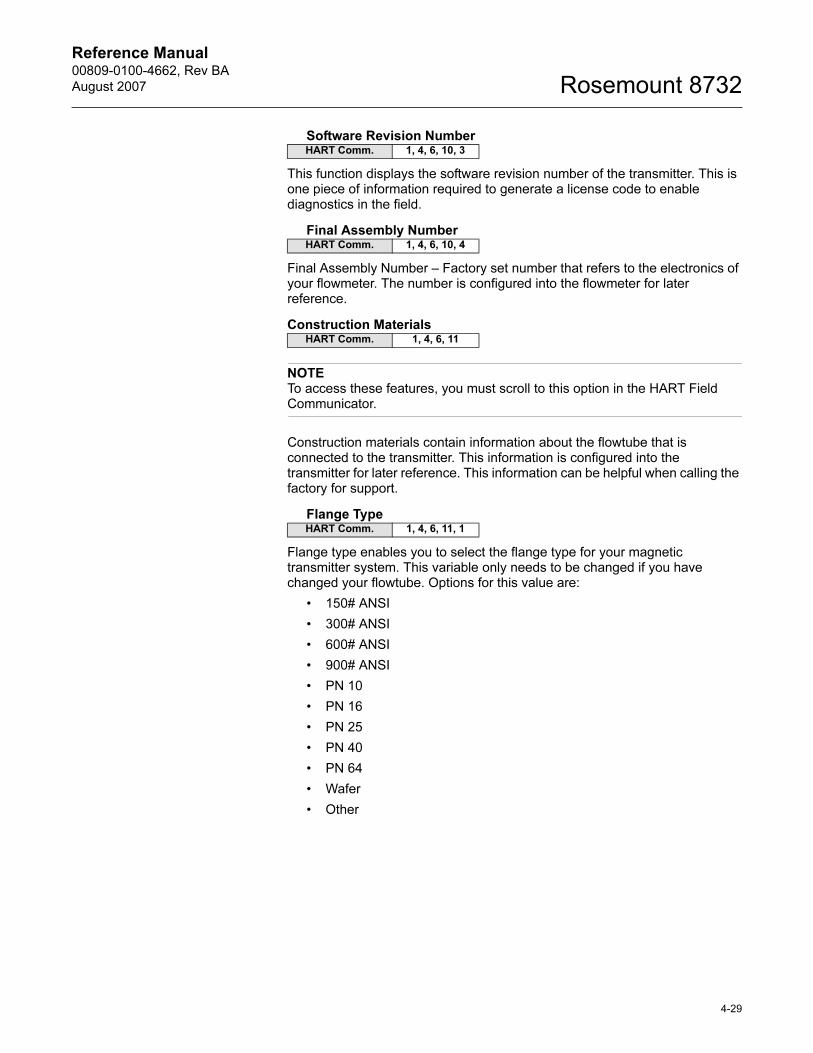
Reference Manual 00809-0100-4662, Rev BA
August 2007 Rosemount 8732
Software Revision Number
This function displays the software revision number of the transmitter. This is one piece of information required to generate a license code to enable diagnostics in the field.
Final Assembly Number
Final Assembly Number – Factory set number that refers to the electronics of your flowmeter. The number is configured into the flowmeter for later reference.
Construction Materials
NOTE To access these features, you must scroll to this option in the HART Field Communicator.
Construction materials contain information about the flowtube that is connected to the transmitter. This information is configured into the transmitter for later reference. This information can be helpful when calling the factory for support.
Flange Type
Flange type enables you to select the flange type for your magnetic transmitter system. This variable only needs to be changed if you have changed your flowtube. Options for this value are:
• 150# ANSI
• 300# ANSI
• 600# ANSI
• 900# ANSI
• PN 10
• PN 16
• PN 25
• PN 40
• PN 64
• Wafer
• Other
HART Comm. 1, 4, 6, 10, 3
HART Comm. 1, 4, 6, 10, 4
HART Comm. 1, 4, 6, 11
HART Comm. 1, 4, 6, 11, 1
4-29
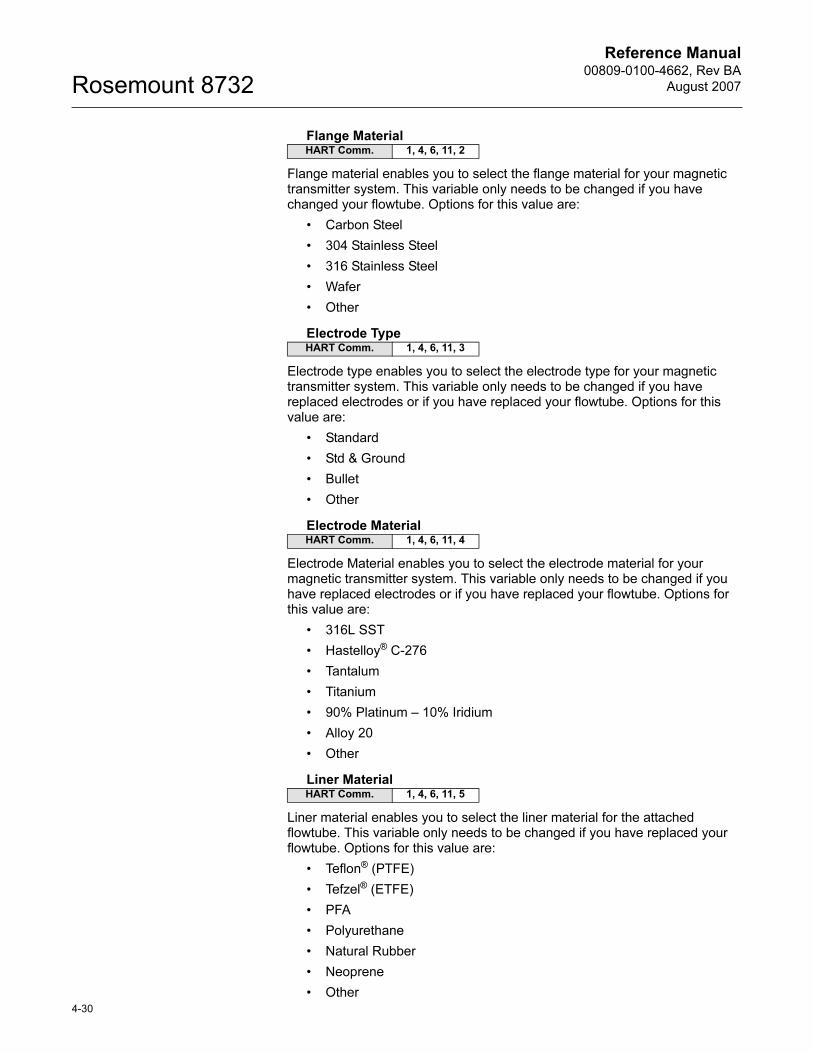
Reference Manual00809-0100-4662, Rev BA
August 2007Rosemount 8732
4-30
Flange Material
Flange material enables you to select the flange material for your magnetic transmitter system. This variable only needs to be changed if you have changed your flowtube. Options for this value are:
• Carbon Steel
• 304 Stainless Steel
• 316 Stainless Steel
• Wafer
• Other
Electrode Type
Electrode type enables you to select the electrode type for your magnetic transmitter system. This variable only needs to be changed if you have replaced electrodes or if you have replaced your flowtube. Options for this value are:
• Standard
• Std & Ground
• Bullet
• Other
Electrode Material
Electrode Material enables you to select the electrode material for your magnetic transmitter system. This variable only needs to be changed if you have replaced electrodes or if you have replaced your flowtube. Options for this value are:
• 316L SST
• Hastelloy® C-276
• Tantalum
• Titanium
• 90% Platinum – 10% Iridium
• Alloy 20
• Other
Liner Material
Liner material enables you to select the liner material for the attached flowtube. This variable only needs to be changed if you have replaced your flowtube. Options for this value are:
• Teflon® (PTFE)
• Tefzel® (ETFE)
• PFA
• Polyurethane
• Natural Rubber
• Neoprene
• Other
HART Comm. 1, 4, 6, 11, 2
HART Comm. 1, 4, 6, 11, 3
HART Comm. 1, 4, 6, 11, 4
HART Comm. 1, 4, 6, 11, 5
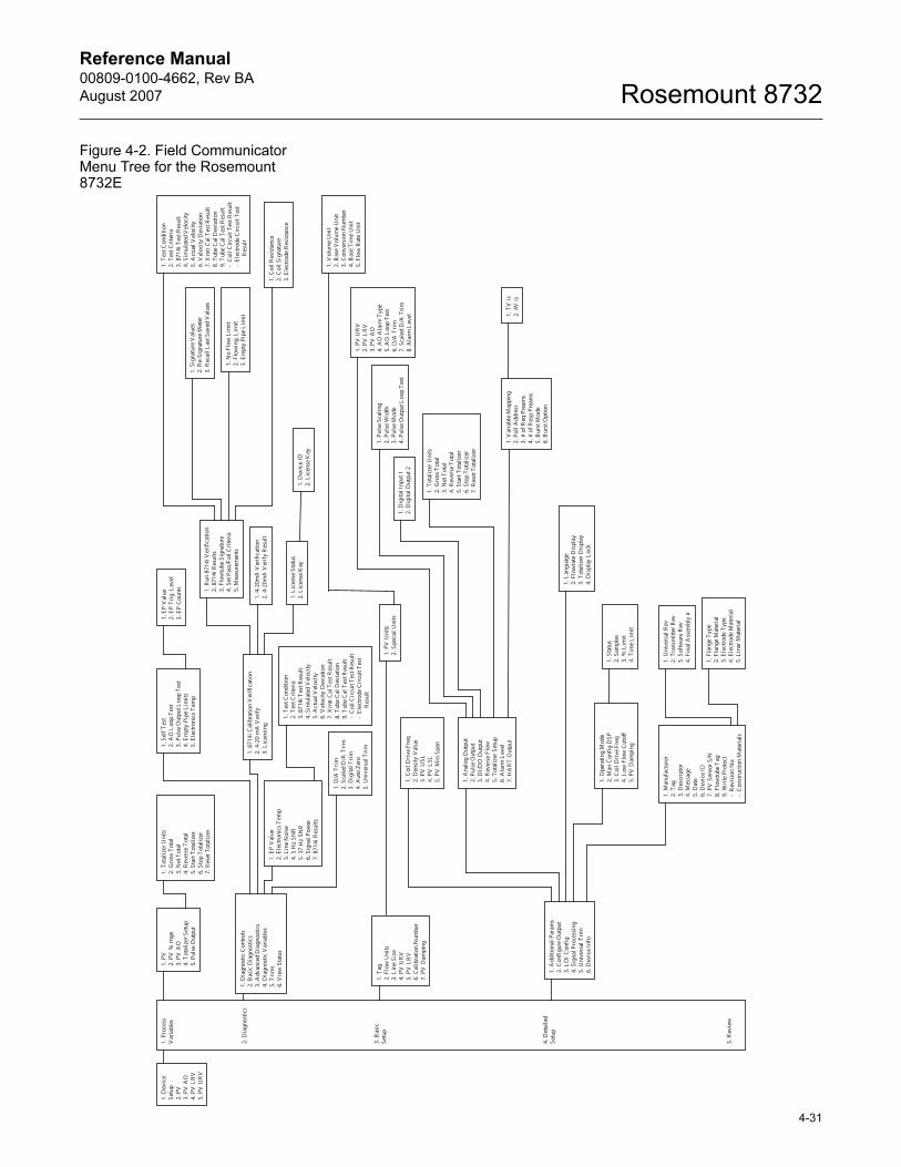
Reference Manual 00809-0100-4662, Rev BA
August 2007 Rosemount 8732
4-31
Figure 4-2. Field Communicator Menu Tree for the Rosemount 8732E
1. D
evic
e Se
tup
2. P
V
3. P
V A
O
4. P
V L
RV
5.
PV
UR
V
1. P
V
2. P
V %
rnge
3.
PV
AO
4.
Tot
aliz
er S
etup
5.
Pul
se O
utpu
t
1. T
otal
izer
Uni
ts
2. G
ross
Tot
al
3. N
et T
otal
4.
Rev
erse
Tot
al
5. S
tart
Tot
aliz
er
6. S
top
Tota
lizer
7.
Res
et T
otal
ize r
1. D
iagn
ostic
Con
trols
2.
Bas
ic D
iagn
ostic
s
3. A
dvan
ced
Dia
gnos
tics
4. D
iagn
ostic
Var
iabl
es
5. T
rim
s 6.
Vie
w S
tatu
s
1. P
roce
ss
Var
iabl
es
2. D
iagn
ostic
s
3. B
asic
Se
tup
4. D
etai
led
Setu
p
5. R
evie
w
1. S
elf T
est
2. A
O L
oop
Test
3.
Pul
se O
utpu
t Loo
p Te
st
4. E
mpt
y Pi
pe L
imits
5.
Ele
ctro
nics
Tem
p
1. E
P V
alue
2.
Ele
ctro
nics
Tem
p 3.
Lin
e N
oise
4.
5 H
z SN
R
5. 3
7 H
z SN
R
6. S
igna
l Pow
er
7. 8
714i
Res
ults
1. P
V U
nits
2.
Spe
cial
Uni
ts
1. V
olum
e U
nit
2. B
ase
Vol
ume
Uni
t 3.
Con
vers
ion
Num
ber
4. B
ase
Tim
e U
nit
5. F
low
Rat
e U
nit
1. A
nalo
g O
utpu
t 2.
Pul
se O
utpu
t 3.
DI/
DO
Out
put
4. R
ever
se F
low
5.
Tot
aliz
er S
etup
6.
Ala
rm L
evel
7.
HA
RT
Out
put
1. P
V U
RV
2.
PV
LR
V
3. P
V A
O
4. A
O A
larm
Typ
e 5.
AO
Loo
p Te
st
6. D
/A T
rim
7.
Sca
led
D/A
Tri
m
8. A
larm
Lev
el
1. P
ulse
Sca
ling
2. P
ulse
Wid
th
3. P
ulse
Mod
e 4.
Pul
se O
utpu
t Loo
p Te
st
1. T
otal
izer
Uni
ts
2. G
ross
Tot
al
3. N
et T
otal
4.
Rev
erse
Tot
al
5. S
tart
Tota
lizer
6.
Sto
p To
taliz
er
7. R
eset
Tot
aliz
e r
1. V
aria
ble
Map
ping
2.
Pol
l Add
ress
3.
# o
f Req
Pre
ams
4.
# o
f Res
p Pr
eam
s 5.
Bur
st M
ode
6. B
urst
Opt
ion
1. O
pera
ting
Mod
e 2.
Man
Con
fig
DSP
3.
Coi
l Dri
ve F
req
4. L
ow F
low
Cut
off
5. P
V D
ampi
ng
1. C
oil D
rive
Fre
q 2.
Den
sity
Val
ue
3. P
V U
SL
4. P
V L
SL
5. P
V M
in S
pan
1. A
dditi
onal
Par
ams
2. C
onfi
gure
Out
put
3. L
OI C
onfi
g 4.
Sig
nal P
roce
ssin
g 5.
Uni
vers
al T
rim
6.
Dev
ice
Info
1. D
igita
l Inp
ut 1
2.
Dig
ital O
utpu
t 2
1. T
ag
2. F
low
Uni
ts
3. L
ine
Size
4.
PV
UR
V
5. P
V L
RV
6.
Cal
ibra
tion
Num
ber
7. P
V D
ampi
ng
1. F
lang
e T
ype
2. F
lang
e M
ater
ial
3. E
lect
rode
Typ
e 4.
Ele
ctro
de M
ater
ial
5. L
iner
Mat
eria
l
1. M
anuf
actu
rer
2. T
ag
3. D
escr
ipto
r 4.
Mes
sage
5.
Dat
e 6.
Dev
ice
ID
7. P
V S
enso
r S/N
8.
Flo
wtu
be T
ag
9. W
rite
Prot
ect
- R
evis
ion
No.
-
Con
stru
ctio
n M
ater
ials
1. U
nive
rsal
Rev
2.
Tra
nsm
itter
Rev
3.
Sof
twar
e R
ev
4. F
inal
Ass
embl
y #
1. S
tatu
s 2.
Sam
ples
3.
% L
imit
4. T
ime
Lim
it
1. L
angu
age
2. F
low
rate
Dis
play
3.
Tot
aliz
er D
ispl
ay
4. D
ispl
ay L
ock
1. D
/A T
rim
2.
Sca
led
D/A
Tri
m
3. D
igita
l Tri
m
4. A
uto
Zero
5.
Uni
vers
al T
rim
1. 8
714i
Cal
ibra
tion
Ver
ifica
tion
2. 4
-20
mA
Ver
ify
3. L
icen
sing
1. R
un 8
714i
Ver
ifica
tion
2. 8
714i
Res
ults
3.
Flo
wtu
be S
igna
ture
4.
Set
Pas
s/Fa
il C
rite
ria
5. M
easu
rem
ents
1. S
igna
ture
Val
ues
2. R
e-Si
gnat
ure
Met
er
3. R
ecal
l Las
t Sav
ed V
alue
s
1. L
icen
se S
tatu
s 2.
Lic
ense
Key
1.
Dev
ice
ID
2. L
icen
se K
ey
1. T
V is
2.
4V
is
1. 4
-20m
A V
erifi
catio
n 2.
4-2
0mA
Ver
ify
Res
ult
1. C
oil R
esis
tanc
e 2.
Coi
l Sig
natu
re
3. E
lect
rode
Res
ista
nce
1. N
o Fl
ow L
imit
2. F
low
ing,
Lim
it 3.
Em
pty
Pipe
Lim
it
1. T
est C
ondi
tion
2. T
est C
riter
ia
3. 8
714i
Tes
t Res
ult
4. S
imul
ated
Vel
ocity
5.
Act
ual V
eloc
ity
6. V
eloc
ity D
evia
tion
7. X
mtr
Cal
Tes
t Res
ult
8. T
ube
Cal
Dev
iatio
n 9.
Tub
e C
al T
est R
esul
t -
Coi
l Cir
cuit
Tes
t Res
ult
- El
ectro
de C
ircu
it Te
st
Res
ult
1. T
est C
ondi
tion
2. T
est C
riter
ia
3. 8
714i
Tes
t Res
ult
4. S
imul
ated
Vel
ocity
5.
Act
ual V
eloc
ity
6. V
eloc
ity D
evia
tion
7. X
mtr
Cal
Tes
t Res
ult
8. T
ube
Cal
Dev
iatio
n 9.
Tub
e C
al T
est R
esul
t -
Coi
l Cir
cuit
Tes
t Res
ult
- El
ectro
de C
ircu
it Te
st
Res
ult
1. E
P V
alue
2.
EP
Trig
. Lev
el
3. E
P C
ount
s
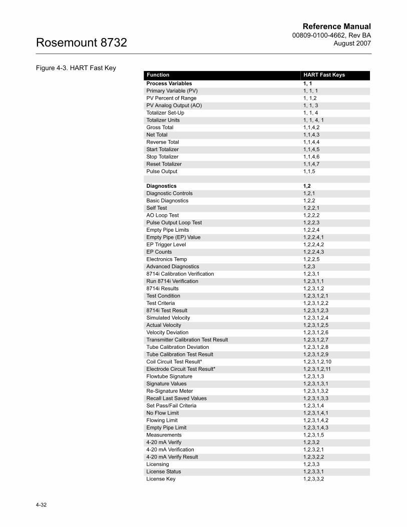
Reference Manual00809-0100-4662, Rev BA
August 2007Rosemount 8732
Figure 4-3. HART Fast KeyFunction HART Fast Keys
Process Variables 1, 1
Primary Variable (PV) 1, 1, 1
PV Percent of Range 1, 1,2
PV Analog Output (AO) 1, 1, 3
Totalizer Set-Up 1, 1, 4
Totalizer Units 1, 1, 4, 1
Gross Total 1,1,4,2
Net Total 1,1,4,3
Reverse Total 1,1,4,4
Start Totalizer 1,1,4,5
Stop Totalizer 1,1,4,6
Reset Totalizer 1,1,4,7
Pulse Output 1,1,5
Diagnostics 1,2
Diagnostic Controls 1,2,1
Basic Diagnostics 1,2,2
Self Test 1,2,2,1
AO Loop Test 1,2,2,2
Pulse Output Loop Test 1,2,2,3
Empty Pipe Limits 1,2,2,4
Empty Pipe (EP) Value 1,2,2,4,1
EP Trigger Level 1,2,2,4,2
EP Counts 1,2,2,4,3
Electronics Temp 1,2,2,5
Advanced Diagnostics 1,2,3
8714i Calibration Verification 1,2,3,1
Run 8714i Verification 1,2,3,1,1
8714i Results 1,2,3,1,2
Test Condition 1,2,3,1,2,1
Test Criteria 1,2,3,1,2,2
8714i Test Result 1,2,3,1,2,3
Simulated Velocity 1,2,3,1,2,4
Actual Velocity 1,2,3,1,2,5
Velocity Deviation 1,2,3,1,2,6
Transmitter Calibration Test Result 1,2,3,1,2,7
Tube Calibration Deviation 1,2,3,1,2,8
Tube Calibration Test Result 1,2,3,1,2,9
Coil Circuit Test Result* 1,2,3,1,2,10
Electrode Circuit Test Result* 1,2,3,1,2,11
Flowtube Signature 1,2,3,1,3
Signature Values 1,2,3,1,3,1
Re-Signature Meter 1,2,3,1,3,2
Recall Last Saved Values 1,2,3,1,3,3
Set Pass/Fail Criteria 1,2,3,1,4
No Flow Limit 1,2,3,1,4,1
Flowing Limit 1,2,3,1,4,2
Empty Pipe Limit 1,2,3,1,4,3
Measurements 1,2,3,1,5
4-20 mA Verify 1,2,3,2
4-20 mA Verification 1,2,3,2,1
4-20 mA Verify Result 1,2,3,2,2
Licensing 1,2,3,3
License Status 1,2,3,3,1
License Key 1,2,3,3,2
4-32
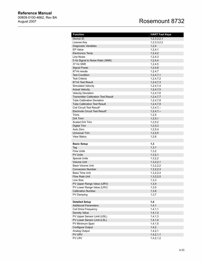
Reference Manual 00809-0100-4662, Rev BA
August 2007 Rosemount 8732
Device ID 1,2,3,3,2,1
License Key 1,2,3,3,2,2
Diagnostic Variables 1,2,4
EP Value 1,2,4,1
Electronics Temp 1,2,4,2
Line Noise 1,2,4,3
5 Hz Signal to Noise Ratio (SNR) 1,2,4,4
37 Hz SNR 1,2,4,5
Signal Power 1,2,4,6
8714i results 1,2,4,7
Test Condition 1,2,4,7,1
Test Criteria 1,2,4,7,2
8714i Test Result 1,2,4,7,3
Simulated Velocity 1,2,4,7,4
Actual Velocity 1,2,4,7,5
Velocity Deviation 1,2,4,7,6
Transmitter Calibration Test Result 1,2,4,7,7
Tube Calibration Deviation 1,2,4,7,8
Tube Calibration Test Result 1,2,4,7,9
Coil Circuit Test Result* 1,2,4,7,--
Electrode Circuit Test Result* 1,2,4,7,--
Trims 1,2,5
D/A Trim\ 1,2,5,1
Scaled D/A Trim 1,2,5,2
Digital Trim 1,2,5,3
Auto Zero 1,2,5,4
Universal Trim 1,2,5,5
View Status 1,2,6
Basic Setup 1,3
Tag 1,3,1
Flow Units 1,3,2
PV Units 1,3,2,1
Special Units 1,3,2,2
Volume Unit 1,3,2,2,1
Base Volume Unit 1,3,2,2,2
Conversion Number 1,3,2,2,3
Base Time Unit 1,3,2,2,4
Flow Rate Unit 1,3,2,2,5
Line Size 1,3,3
PV Upper Range Value (URV) 1,3,4
PV Lower Range Value (LRV) 1,3,5
Calibration Number 1,3,6
PV Damping 1,3,7
Detailed Setup 1,4
Additional Parameters 1,4,1
Coil Drive Frequency 1,4,1,1
Density Value 1,4,1,2
PV Upper Sensor Limit (USL) 1,4,1,3
PV Lower Sensor Limit (LSL) 1,4,1,4
PV Minimum Span 1,4,1,5
Configure Output 1,4,2
Analog Output 1,4,2,1
PV URV 1,4,2,1,1
PV LRV 1,4,2,1,2
Function HART Fast Keys
4-33
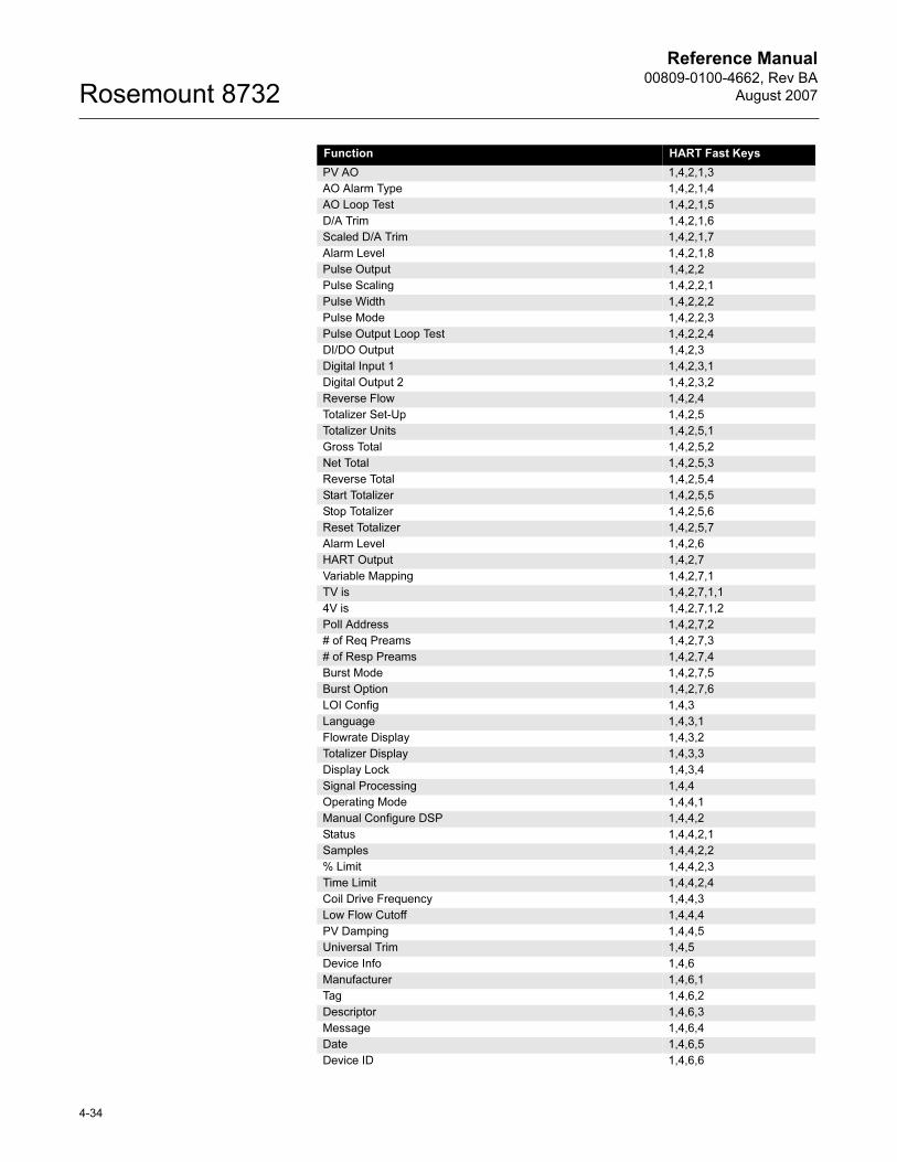
Reference Manual00809-0100-4662, Rev BA
August 2007Rosemount 8732
PV AO 1,4,2,1,3
AO Alarm Type 1,4,2,1,4
AO Loop Test 1,4,2,1,5
D/A Trim 1,4,2,1,6
Scaled D/A Trim 1,4,2,1,7
Alarm Level 1,4,2,1,8
Pulse Output 1,4,2,2
Pulse Scaling 1,4,2,2,1
Pulse Width 1,4,2,2,2
Pulse Mode 1,4,2,2,3
Pulse Output Loop Test 1,4,2,2,4
DI/DO Output 1,4,2,3
Digital Input 1 1,4,2,3,1
Digital Output 2 1,4,2,3,2
Reverse Flow 1,4,2,4
Totalizer Set-Up 1,4,2,5
Totalizer Units 1,4,2,5,1
Gross Total 1,4,2,5,2
Net Total 1,4,2,5,3
Reverse Total 1,4,2,5,4
Start Totalizer 1,4,2,5,5
Stop Totalizer 1,4,2,5,6
Reset Totalizer 1,4,2,5,7
Alarm Level 1,4,2,6
HART Output 1,4,2,7
Variable Mapping 1,4,2,7,1
TV is 1,4,2,7,1,1
4V is 1,4,2,7,1,2
Poll Address 1,4,2,7,2
# of Req Preams 1,4,2,7,3
# of Resp Preams 1,4,2,7,4
Burst Mode 1,4,2,7,5
Burst Option 1,4,2,7,6
LOI Config 1,4,3
Language 1,4,3,1
Flowrate Display 1,4,3,2
Totalizer Display 1,4,3,3
Display Lock 1,4,3,4
Signal Processing 1,4,4
Operating Mode 1,4,4,1
Manual Configure DSP 1,4,4,2
Status 1,4,4,2,1
Samples 1,4,4,2,2
% Limit 1,4,4,2,3
Time Limit 1,4,4,2,4
Coil Drive Frequency 1,4,4,3
Low Flow Cutoff 1,4,4,4
PV Damping 1,4,4,5
Universal Trim 1,4,5
Device Info 1,4,6
Manufacturer 1,4,6,1
Tag 1,4,6,2
Descriptor 1,4,6,3
Message 1,4,6,4
Date 1,4,6,5
Device ID 1,4,6,6
Function HART Fast Keys
4-34
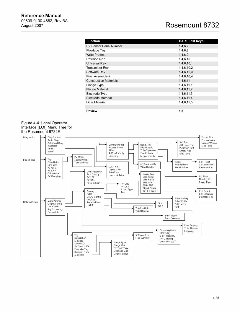
Reference Manual 00809-0100-4662, Rev BA
August 2007 Rosemount 8732
4-35
Figure 4-4. Local Operator Interface (LOI) Menu Tree for the Rosemount 8732E
PV Sensor Serial Number 1,4,6,7
Flowtube Tag 1,4,6,8
Write Protect 1,4,6,9
Revision No.* 1,4,6,10
Universal Rev 1,4,6,10,1
Transmitter Rev 1,4,6,10,2
Software Rev 1,4,6,10,3
Final Assembly # 1,4,6,10,4
Construction Materials* 1,4,6,11
Flange Type 1,4,6,11,1
Flange Material 1,4,6,11,2
Electrode Type 1,4,6,11,3
Electrode Material 1,4,6,11,4
Liner Material 1,4,6,11,5
Review 1,5
Function HART Fast Keys
Diag Controls B asic Diag A dvanced Diag V ariablesT rims Status
E mpty Pipe Process Noise Ground/WiringE lec T emp
Self T est A O L oop T est Pulse Out T est E mpty Pipe E lec T emp
Ground/WiringProcess Noise 8714i4-20 mA V erify L icensing
R un 8714i V iew R esults T ube SignatureT est Criteria Measurements
V aluesR e-Signature R ecall V alues
Coil R esist Coil Signature E lectrode R es
No Flow Flowing, Full E mpty Pipe
Coil R esist Coil Signature E lectrode R es
E mpty Pipe E lec T emp L ine Noise 5Hz SNR 37Hz SNR Signal Power 8714i R esults
D/A T rim Digital T rim A uto Zero Universal T rim
4-20 mA V erify V iew R esults
T agFlow Units L ine Size PV UR V PV L R V Cal Number PV Damping
Coil FrequencyProc Density PV L SL PV USL PV Min Span
A nalogPulse DI/DO Config T otalizer R everse Flow HA R T
PV UR V PV L R V A larm T ype T est
Pulse Scaling Pulse Width Pulse Mode T est
DI 1 DO 2
T otalize Units T otal Display
B urst Mode B urst Command
Flange T ype Flange Matl E lectrode T ypeE lectrode Matl L iner Material
Software R ev Final A smbl #
T agDescriptionMessage Device ID PV Sensor S/N Flowtube T ag R evision Num Materials
Operating Mode SP Config Coil Frequency PV Damping L o-Flow Cutoff
Flow Display T otal Display L anguage
More Params Output Config L OI Config Sig Processing Device Info
PV Units Special Units T otalize Units
Diagnostics
B asic Setup
Detailed Setup

Reference Manual00809-0100-4662, Rev BA
August 2007Rosemount 8732
4-36
Reference Manual 00809-0100-4662, Rev BA
August 2007 Rosemount 8732
Section 5 Flowtube Installation
Safety Messages . . . . . . . . . . . . . . . . . . . . . . . . . . . . . . . . . page 5-1
Flowtube Handling . . . . . . . . . . . . . . . . . . . . . . . . . . . . . . . page 5-3
Flowtube Mounting . . . . . . . . . . . . . . . . . . . . . . . . . . . . . . . page 5-4
Installation (Flanged Flowtube) . . . . . . . . . . . . . . . . . . . . . page 5-7
Installation (Wafer Flowtube) . . . . . . . . . . . . . . . . . . . . . . . page 5-10
Installation (Sanitary Flowtube) . . . . . . . . . . . . . . . . . . . . . page 5-12
Grounding . . . . . . . . . . . . . . . . . . . . . . . . . . . . . . . . . . . . . . page 5-12
Process Leak Protection (Optional) . . . . . . . . . . . . . . . . . page 5-16
This section covers the steps required to physically install the magnetic flowtube. For electrical connections and cabling see Section 2: Installation. Instructions and procedures in this section may require special precautions to ensure the safety of the personnel performing the operations. Please refer to the following safety messages before performing any operation in this section.
SAFETY MESSAGES This symbol is used throughout this manual to indicate that special attention to warning information is required.
Failure to follow these installation guidelines could result in death or serious injury:
Installation and servicing instructions are for use by qualified personnel only. Do not perform
any servicing other than that contained in the operating instructions, unless qualified. Verify
that the operating environment of the flowtube and transmitter is consistent with the
appropriate hazardous area approval.
Do not connect a Rosemount 8732E to a non-Rosemount flowtube that is located in an
explosive atmosphere.
www.rosemount.com
Reference Manual00809-0100-4662, Rev BA
August 2007Rosemount 8732
Explosions could result in death or serious injury:
Installation of this transmitter in an explosive environment must be in accordance with the
appropriate local, national, and international standards, codes, and practices. Please review
the approvals section of the 8732E reference manual for any restrictions associated with a
safe installation.
Before connecting a HART-based communicator in an explosive atmosphere, make sure
the instruments in the loop are installed in accordance with intrinsically safe or
non-incendive field wiring practices.
Electrical shock can result in death or serious injury
Avoid contact with the leads and terminals. High voltage that may be present on leads can
cause electrical shock.
The flowtube liner is vulnerable to handling damage. Never place anything through the
flowtube for the purpose of lifting or gaining leverage. Liner damage can render the flowtube
useless.
To avoid possible damage to the flowtube liner ends, do not use metallic or spiral-wound
gaskets. If frequent removal is anticipated, take precautions to protect the liner ends. Short
spool pieces attached to the flowtube ends are often used for protection.
Correct flange bolt tightening is crucial for proper flowtube operation and life. All bolts must
be tightened in the proper sequence to the specified torque limits. Failure to observe these
instructions could result in severe damage to the flowtube lining and possible flowtube
replacement.
Emerson Process Management can supply lining protectors to prevent liner damage during
removal, installation, and excessive bolt torquing.
5-2
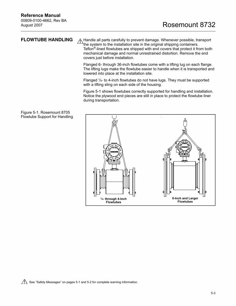
Reference Manual 00809-0100-4662, Rev BA
August 2007 Rosemount 8732
FLOWTUBE HANDLING Handle all parts carefully to prevent damage. Whenever possible, transport the system to the installation site in the original shipping containers. Teflon®-lined flowtubes are shipped with end covers that protect it from both mechanical damage and normal unrestrained distortion. Remove the end covers just before installation.
Flanged 6- through 36-inch flowtubes come with a lifting lug on each flange. The lifting lugs make the flowtube easier to handle when it is transported and lowered into place at the installation site.
Flanged ½- to 4-inch flowtubes do not have lugs. They must be supported with a lifting sling on each side of the housing.
Figure 5-1 shows flowtubes correctly supported for handling and installation. Notice the plywood end pieces are still in place to protect the flowtube liner during transportation.
Figure 5-1. Rosemount 8705 Flowtube Support for Handling
See ”Safety Messages” on pages 5-1 and 5-2 for complete warning information.
½- through 4-Inch Flowtubes
6-Inch and Larger Flowtubes
5-3
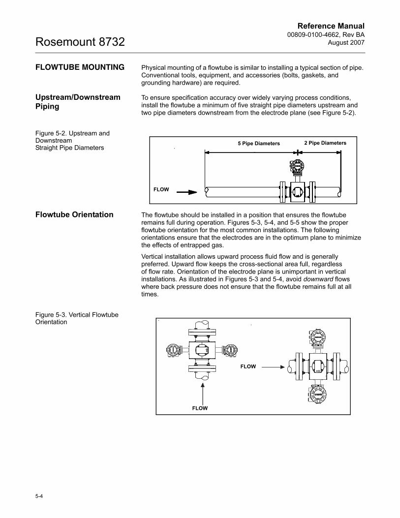
Reference Manual00809-0100-4662, Rev BA
August 2007Rosemount 8732
FLOWTUBE MOUNTING Physical mounting of a flowtube is similar to installing a typical section of pipe. Conventional tools, equipment, and accessories (bolts, gaskets, and grounding hardware) are required.
Upstream/DownstreamPiping
To ensure specification accuracy over widely varying process conditions, install the flowtube a minimum of five straight pipe diameters upstream and two pipe diameters downstream from the electrode plane (see Figure 5-2).
Figure 5-2. Upstream and Downstream Straight Pipe Diameters
Flowtube Orientation The flowtube should be installed in a position that ensures the flowtube remains full during operation. Figures 5-3, 5-4, and 5-5 show the proper flowtube orientation for the most common installations. The following orientations ensure that the electrodes are in the optimum plane to minimize the effects of entrapped gas.
Vertical installation allows upward process fluid flow and is generally preferred. Upward flow keeps the cross-sectional area full, regardless of flow rate. Orientation of the electrode plane is unimportant in vertical installations. As illustrated in Figures 5-3 and 5-4, avoid downward flows where back pressure does not ensure that the flowtube remains full at all times.
Figure 5-3. Vertical Flowtube Orientation
FLOW
5 Pipe Diameters 2 Pipe Diameters
FLOW
FLOW
5-4
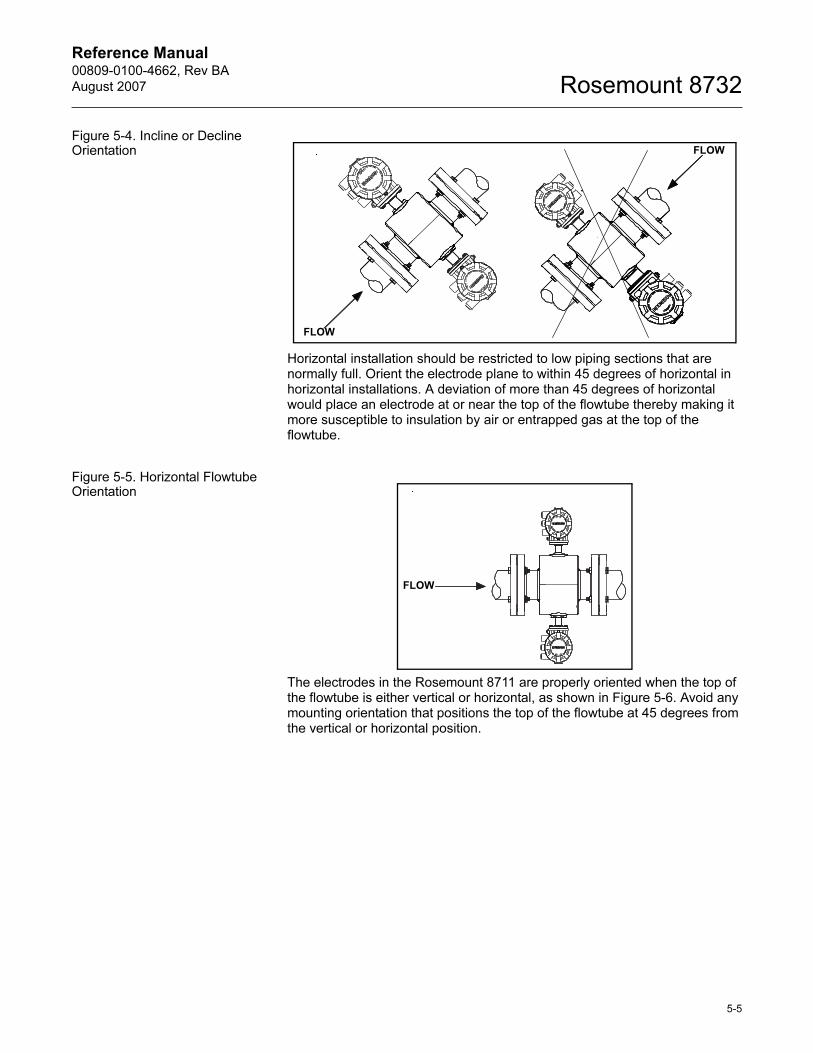
Reference Manual 00809-0100-4662, Rev BA
August 2007 Rosemount 8732
Figure 5-4. Incline or Decline Orientation
Horizontal installation should be restricted to low piping sections that are normally full. Orient the electrode plane to within 45 degrees of horizontal in horizontal installations. A deviation of more than 45 degrees of horizontal would place an electrode at or near the top of the flowtube thereby making it more susceptible to insulation by air or entrapped gas at the top of the flowtube.
Figure 5-5. Horizontal Flowtube Orientation
The electrodes in the Rosemount 8711 are properly oriented when the top of the flowtube is either vertical or horizontal, as shown in Figure 5-6. Avoid any mounting orientation that positions the top of the flowtube at 45 degrees from the vertical or horizontal position.
FLOW
FLOW
FLOW
5-5
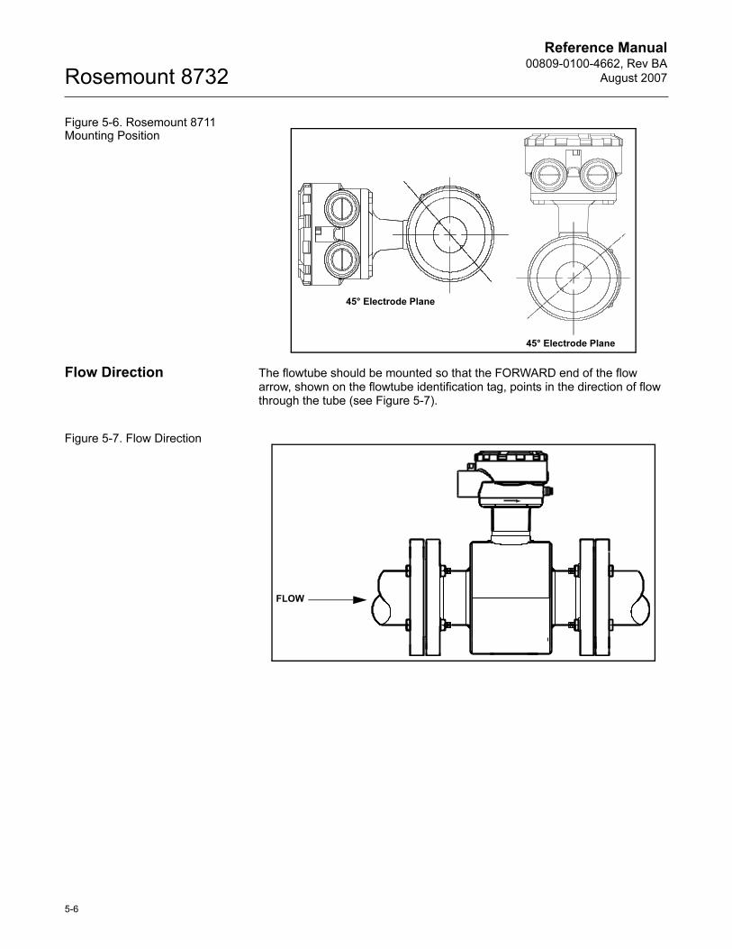
Reference Manual00809-0100-4662, Rev BA
August 2007Rosemount 8732
Figure 5-6. Rosemount 8711 Mounting Position
Flow Direction The flowtube should be mounted so that the FORWARD end of the flow arrow, shown on the flowtube identification tag, points in the direction of flow through the tube (see Figure 5-7).
Figure 5-7. Flow Direction
45° Electrode Plane
45° Electrode Plane
FLOW
5-6
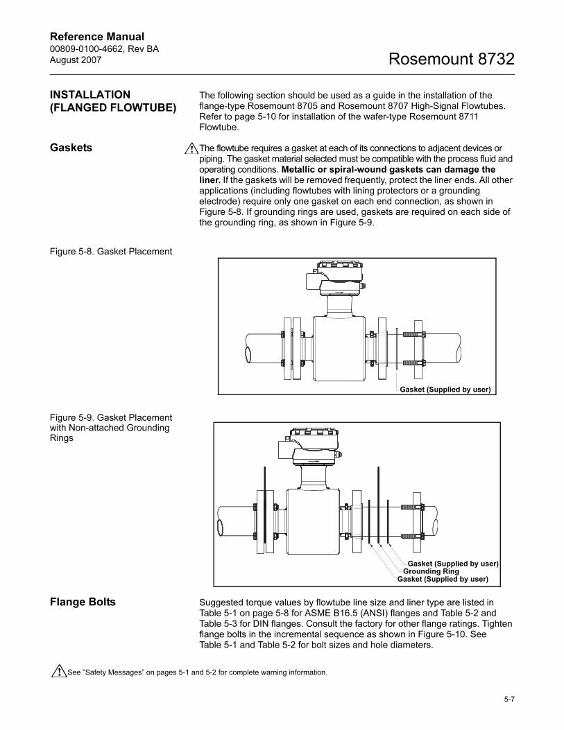
Reference Manual 00809-0100-4662, Rev BA
August 2007 Rosemount 8732
INSTALLATION (FLANGED FLOWTUBE)
The following section should be used as a guide in the installation of the flange-type Rosemount 8705 and Rosemount 8707 High-Signal Flowtubes. Refer to page 5-10 for installation of the wafer-type Rosemount 8711 Flowtube.
Gaskets The flowtube requires a gasket at each of its connections to adjacent devices or piping. The gasket material selected must be compatible with the process fluid and operating conditions. Metallic or spiral-wound gaskets can damage the liner. If the gaskets will be removed frequently, protect the liner ends. All other applications (including flowtubes with lining protectors or a grounding electrode) require only one gasket on each end connection, as shown in Figure 5-8. If grounding rings are used, gaskets are required on each side of the grounding ring, as shown in Figure 5-9.
Figure 5-8. Gasket Placement
Figure 5-9. Gasket Placement with Non-attached Grounding Rings
Flange Bolts Suggested torque values by flowtube line size and liner type are listed in Table 5-1 on page 5-8 for ASME B16.5 (ANSI) flanges and Table 5-2 and Table 5-3 for DIN flanges. Consult the factory for other flange ratings. Tighten flange bolts in the incremental sequence as shown in Figure 5-10. See Table 5-1 and Table 5-2 for bolt sizes and hole diameters.
See ”Safety Messages” on pages 5-1 and 5-2 for complete warning information.
Gasket (Supplied by user)
Gasket (Supplied by user)Grounding Ring
Gasket (Supplied by user)
5-7
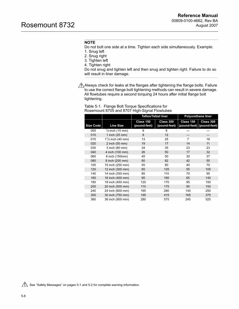
Reference Manual00809-0100-4662, Rev BA
August 2007Rosemount 8732
NOTEDo not bolt one side at a time. Tighten each side simultaneously. Example: 1. Snug left2. Snug right3. Tighten left4. Tighten rightDo not snug and tighten left and then snug and tighten right. Failure to do so will result in liner damage.
Always check for leaks at the flanges after tightening the flange bolts. Failure to use the correct flange bolt tightening methods can result in severe damage. All flowtubes require a second torquing 24 hours after initial flange bolt tightening.
Table 5-1. Flange Bolt Torque Specifications for Rosemount 8705 and 8707 High-Signal Flowtubes
Teflon/Tefzel liner Polyurethane liner
Size Code Line Size
Class 150
(pound-feet)
Class 300
(pound-feet)
Class 150
(pound-feet)
Class 300
(pound-feet)
005 1/2-inch (15 mm) 8 8 — —
010 1 inch (25 mm) 8 12 — —
015 11/2 inch (40 mm) 13 25 7 18
020 2 inch (50 mm) 19 17 14 11
030 3 inch (80 mm) 34 35 23 23
040 4 inch (100 mm) 26 50 17 32
060 6 inch (150mm) 45 50 30 37
080 8 inch (200 mm) 60 82 42 55
100 10 inch (250 mm) 55 80 40 70
120 12 inch (300 mm) 65 125 55 105
140 14 inch (350 mm) 85 110 70 95
160 16 inch (400 mm) 85 160 65 140
180 18 inch (450 mm) 120 170 95 150
200 20 inch (500 mm) 110 175 90 150
240 24 inch (600 mm) 165 280 140 250
300 30 inch (750 mm) 195 415 165 375
360 36 inch (900 mm) 280 575 245 525
See ”Safety Messages” on pages 5-1 and 5-2 for complete warning information.
5-8
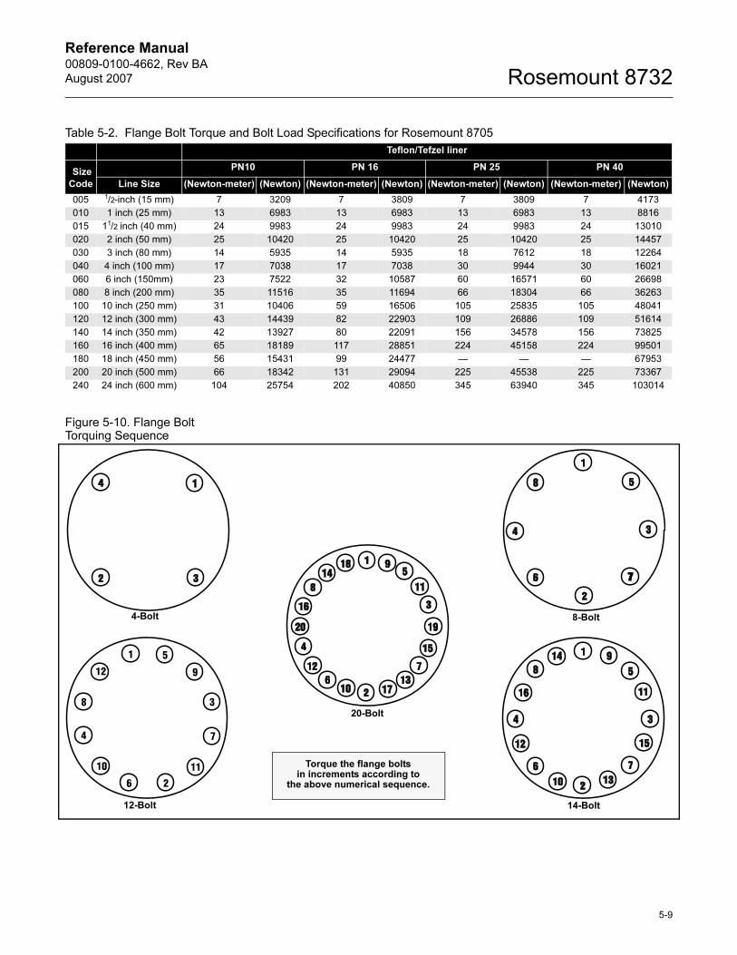
Reference Manual 00809-0100-4662, Rev BA
August 2007 Rosemount 8732
Figure 5-10. Flange Bolt Torquing Sequence
Table 5-2. Flange Bolt Torque and Bolt Load Specifications for Rosemount 8705
Teflon/Tefzel liner
Size
Code
PN10 PN 16 PN 25 PN 40
Line Size (Newton-meter) (Newton) (Newton-meter) (Newton) (Newton-meter) (Newton) (Newton-meter) (Newton)
005 1/2-inch (15 mm) 7 3209 7 3809 7 3809 7 4173
010 1 inch (25 mm) 13 6983 13 6983 13 6983 13 8816
015 11/2 inch (40 mm) 24 9983 24 9983 24 9983 24 13010
020 2 inch (50 mm) 25 10420 25 10420 25 10420 25 14457
030 3 inch (80 mm) 14 5935 14 5935 18 7612 18 12264
040 4 inch (100 mm) 17 7038 17 7038 30 9944 30 16021
060 6 inch (150mm) 23 7522 32 10587 60 16571 60 26698
080 8 inch (200 mm) 35 11516 35 11694 66 18304 66 36263
100 10 inch (250 mm) 31 10406 59 16506 105 25835 105 48041
120 12 inch (300 mm) 43 14439 82 22903 109 26886 109 51614
140 14 inch (350 mm) 42 13927 80 22091 156 34578 156 73825
160 16 inch (400 mm) 65 18189 117 28851 224 45158 224 99501
180 18 inch (450 mm) 56 15431 99 24477 — — — 67953
200 20 inch (500 mm) 66 18342 131 29094 225 45538 225 73367
240 24 inch (600 mm) 104 25754 202 40850 345 63940 345 103014
4-Bolt 8-Bolt
12-Bolt 14-Bolt
20-Bolt
Torque the flange bolts in increments according to
the above numerical sequence.
5-9
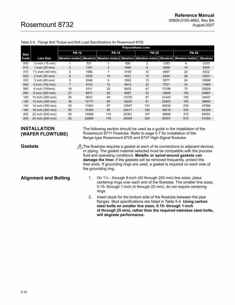
Reference Manual00809-0100-4662, Rev BA
August 2007Rosemount 8732
INSTALLATION (WAFER FLOWTUBE)
The following section should be used as a guide in the installation of the Rosemount 8711 Flowtube. Refer to page 5-7 for installation of the flange-type Rosemount 8705 and 8707 High-Signal flowtube.
Gaskets The flowtube requires a gasket at each of its connections to adjacent devices or piping. The gasket material selected must be compatible with the process fluid and operating conditions. Metallic or spiral-wound gaskets can damage the liner. If the gaskets will be removed frequently, protect the liner ends. If grounding rings are used, a gasket is required on each side of the grounding ring.
Alignment and Bolting 1. On 11/2 - through 8-inch (40 through 200 mm) line sizes, place centering rings over each end of the flowtube. The smaller line sizes, 0.15- through 1-inch (4 through 25 mm), do not require centering rings.
2. Insert studs for the bottom side of the flowtube between the pipe flanges. Stud specifications are listed in Table 5-4. Using carbon steel bolts on smaller line sizes, 0.15- through 1-inch (4 through 25 mm), rather than the required stainless steel bolts, will degrade performance.
Table 5-3. Flange Bolt Torque and Bolt Load Specifications for Rosemount 8705
Size
Code Line Size
Polyurethane Liner
PN 10 PN 16 PN 25 PN 40
(Newton-meter) (Newton) (Newton-meter) (Newton) (Newton-meter) (Newton) (Newton-meter) (Newton)
005 1/2-inch (15 mm) 1 521 1 826 2 1293 6 3333
010 1 inch (25 mm) 2 1191 3 1890 5 2958 10 5555
015 11/2 inch (40 mm) 5 1960 7 3109 12 4867 20 8332
020 2 inch (50 mm) 6 2535 10 4021 15 6294 26 10831
030 3 inch (80 mm) 5 2246 9 3563 13 5577 24 19998
040 4 inch (100 mm) 7 3033 12 4812 23 7531 35 11665
060 6 inch (150mm) 16 5311 25 8425 47 13186 75 20829
080 8 inch (200 mm) 27 8971 28 9487 53 14849 100 24687
100 10 inch (250 mm) 26 8637 49 13700 87 21443 155 34547
120 12 inch (300 mm) 36 12117 69 19220 91 22563 165 36660
140 14 inch (350 mm) 35 11693 67 18547 131 29030 235 47466
160 16 inch (400 mm) 55 15393 99 24417 189 38218 335 62026
200 20 inch (500 mm) 58 15989 114 25361 197 39696 375 64091
240 24 inch (600 mm) 92 22699 178 36006 304 56357 615 91094
5-10
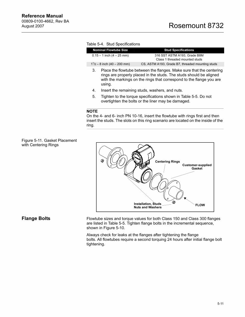
Reference Manual 00809-0100-4662, Rev BA
August 2007 Rosemount 8732
3. Place the flowtube between the flanges. Make sure that the centering rings are properly placed in the studs. The studs should be aligned with the markings on the rings that correspond to the flange you are using.
4. Insert the remaining studs, washers, and nuts.
5. Tighten to the torque specifications shown in Table 5-5. Do not overtighten the bolts or the liner may be damaged.
NOTEOn the 4- and 6- inch PN 10-16, insert the flowtube with rings first and then insert the studs. The slots on this ring scenario are located on the inside of the ring.
Figure 5-11. Gasket Placement with Centering Rings
Flange Bolts Flowtube sizes and torque values for both Class 150 and Class 300 flanges are listed in Table 5-5. Tighten flange bolts in the incremental sequence, shown in Figure 5-10.
Always check for leaks at the flanges after tightening the flange bolts. All flowtubes require a second torquing 24 hours after initial flange bolt tightening.
Table 5-4. Stud Specifications
Nominal Flowtube Size Stud Specifications
0.15 – 1 inch (4 – 25 mm) 316 SST ASTM A193, Grade B8M
Class 1 threaded mounted studs
11/2 – 8 inch (40 – 200 mm) CS, ASTM A193, Grade B7, threaded mounting studs
Customer-supplied Gasket
FLOWInstallation, Studs Nuts and Washers
Centering Rings
5-11
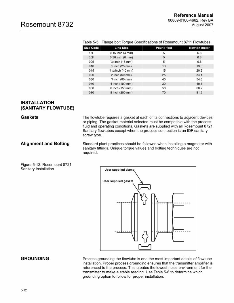
Reference Manual00809-0100-4662, Rev BA
August 2007Rosemount 8732
INSTALLATION (SANITARY FLOWTUBE)
Gaskets The flowtube requires a gasket at each of its connections to adjacent devices or piping. The gasket material selected must be compatible with the process fluid and operating conditions. Gaskets are supplied with all Rosemount 8721 Sanitary flowtubes except when the process connection is an IDF sanitary screw type.
Alignment and Bolting Standard plant practices should be followed when installing a magmeter with sanitary fittings. Unique torque values and bolting techniques are not required.
Figure 5-12. Rosemount 8721 Sanitary Installation
GROUNDING Process grounding the flowtube is one the most important details of flowtube installation. Proper process grounding ensures that the transmitter amplifier is referenced to the process. This creates the lowest noise environment for the transmitter to make a stable reading. Use Table 5-6 to determine which grounding option to follow for proper installation.
Table 5-5. Flange bolt Torque Specifications of Rosemount 8711 Flowtubes
Size Code Line Size Pound-feet Newton-meter
15F 0.15 inch (4 mm) 5 6.8
30F 0.30 inch (8 mm) 5 6.8
005 1/2-inch (15 mm) 5 6.8
010 1 inch (25 mm) 10 13.6
015 11/2 inch (40 mm) 15 20.5
020 2 inch (50 mm) 25 34.1
030 3 inch (80 mm) 40 54.6
040 4 inch (100 mm) 30 40.1
060 6 inch (150 mm) 50 68.2
080 8 inch (200 mm) 70 81.9
User supplied clamp
User supplied gasket
5-12
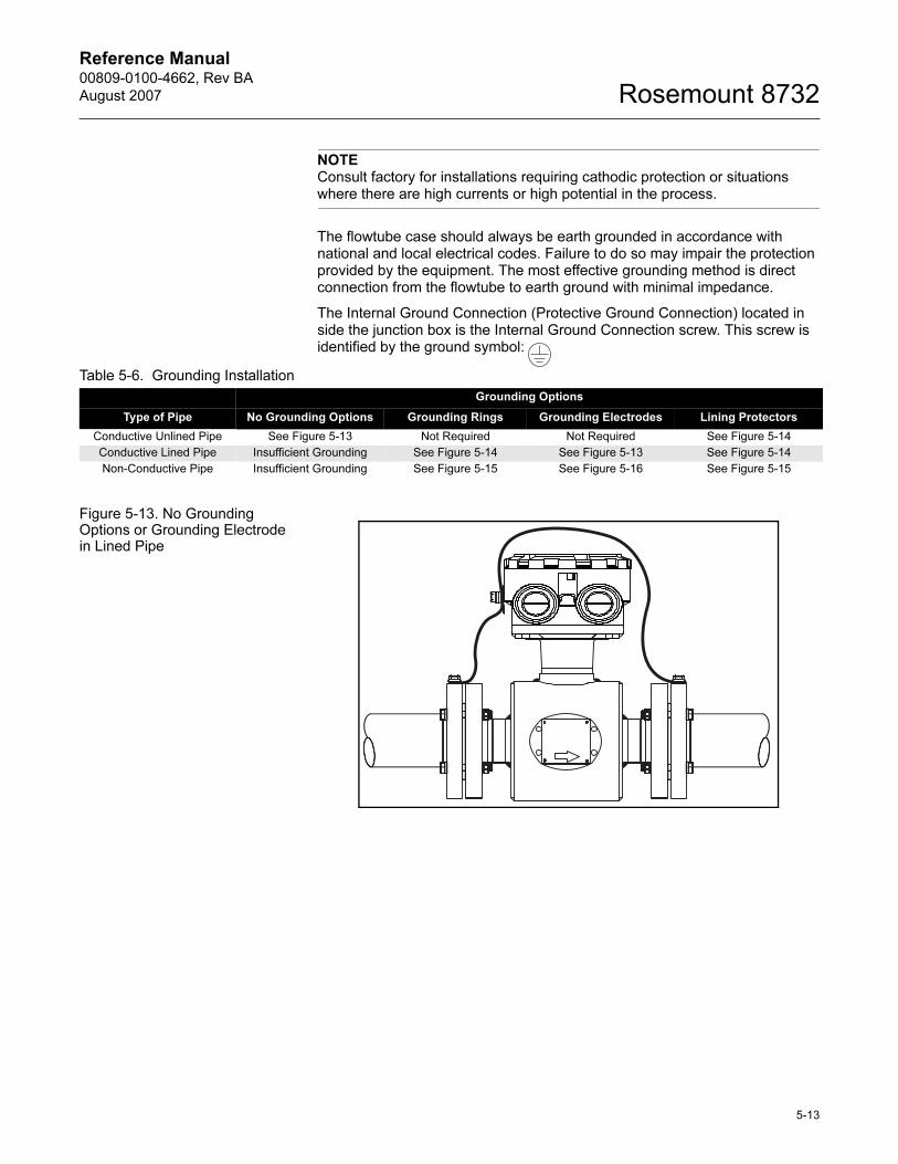
Reference Manual 00809-0100-4662, Rev BA
August 2007 Rosemount 8732
NOTEConsult factory for installations requiring cathodic protection or situations where there are high currents or high potential in the process.
The flowtube case should always be earth grounded in accordance with national and local electrical codes. Failure to do so may impair the protection provided by the equipment. The most effective grounding method is direct connection from the flowtube to earth ground with minimal impedance.
The Internal Ground Connection (Protective Ground Connection) located in side the junction box is the Internal Ground Connection screw. This screw is identified by the ground symbol:
Figure 5-13. No Grounding Options or Grounding Electrode in Lined Pipe
Table 5-6. Grounding Installation
Grounding Options
Type of Pipe No Grounding Options Grounding Rings Grounding Electrodes Lining Protectors
Conductive Unlined Pipe See Figure 5-13 Not Required Not Required See Figure 5-14
Conductive Lined Pipe Insufficient Grounding See Figure 5-14 See Figure 5-13 See Figure 5-14
Non-Conductive Pipe Insufficient Grounding See Figure 5-15 See Figure 5-16 See Figure 5-15
5-13
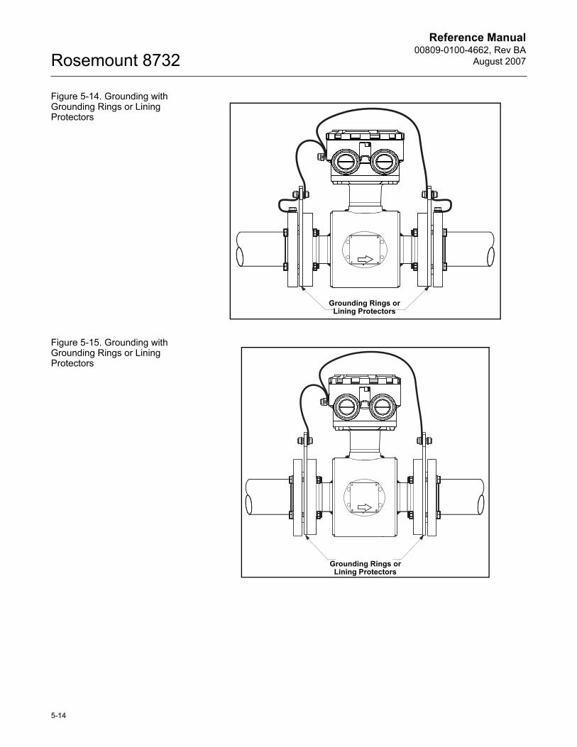
Reference Manual00809-0100-4662, Rev BA
August 2007Rosemount 8732
Figure 5-14. Grounding with Grounding Rings or Lining Protectors
Figure 5-15. Grounding with Grounding Rings or Lining Protectors
Grounding Rings or Lining Protectors
Grounding Rings or Lining Protectors
5-14
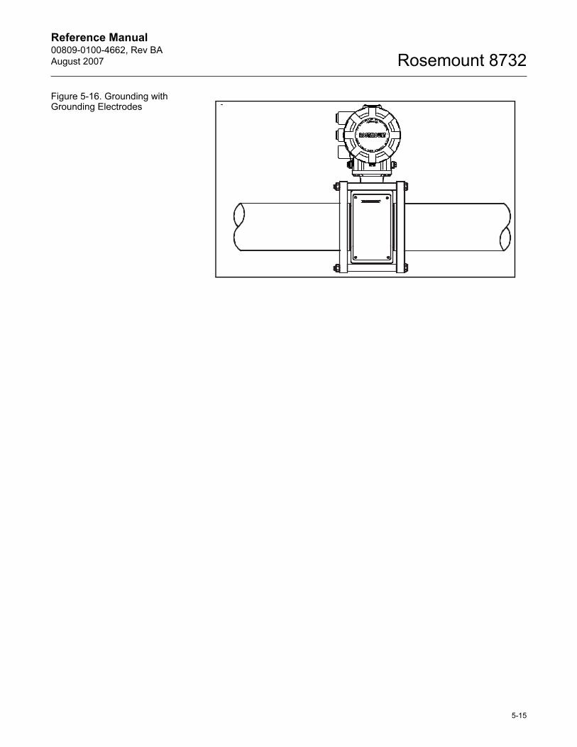
Reference Manual 00809-0100-4662, Rev BA
August 2007 Rosemount 8732
Figure 5-16. Grounding with Grounding Electrodes
5-15
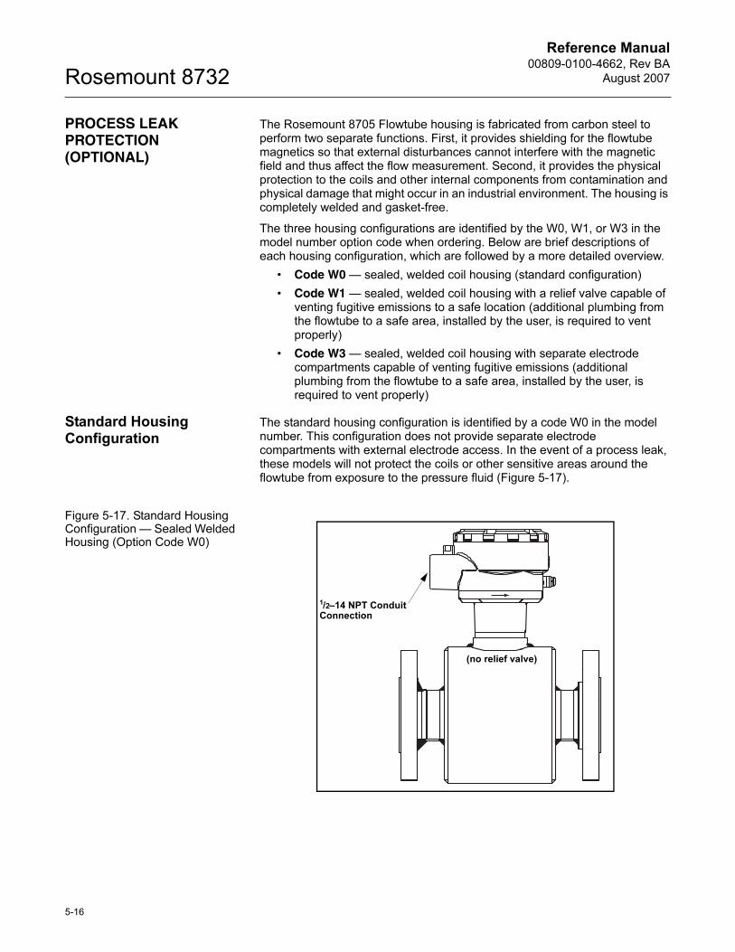
Reference Manual00809-0100-4662, Rev BA
August 2007Rosemount 8732
PROCESS LEAK PROTECTION (OPTIONAL)
The Rosemount 8705 Flowtube housing is fabricated from carbon steel to perform two separate functions. First, it provides shielding for the flowtube magnetics so that external disturbances cannot interfere with the magnetic field and thus affect the flow measurement. Second, it provides the physical protection to the coils and other internal components from contamination and physical damage that might occur in an industrial environment. The housing is completely welded and gasket-free.
The three housing configurations are identified by the W0, W1, or W3 in the model number option code when ordering. Below are brief descriptions of each housing configuration, which are followed by a more detailed overview.
• Code W0 — sealed, welded coil housing (standard configuration)
• Code W1 — sealed, welded coil housing with a relief valve capable of venting fugitive emissions to a safe location (additional plumbing from the flowtube to a safe area, installed by the user, is required to vent properly)
• Code W3 — sealed, welded coil housing with separate electrode compartments capable of venting fugitive emissions (additional plumbing from the flowtube to a safe area, installed by the user, is required to vent properly)
Standard Housing Configuration
The standard housing configuration is identified by a code W0 in the model number. This configuration does not provide separate electrode compartments with external electrode access. In the event of a process leak, these models will not protect the coils or other sensitive areas around the flowtube from exposure to the pressure fluid (Figure 5-17).
Figure 5-17. Standard Housing Configuration — Sealed Welded Housing (Option Code W0)
1/2–14 NPT Conduit Connection
(no relief valve)
5-16
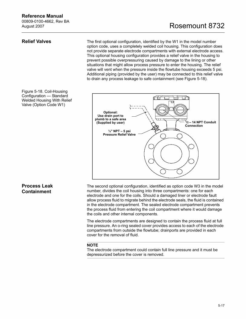
Reference Manual 00809-0100-4662, Rev BA
August 2007 Rosemount 8732
Relief Valves The first optional configuration, identified by the W1 in the model number option code, uses a completely welded coil housing. This configuration does not provide separate electrode compartments with external electrode access. This optional housing configuration provides a relief valve in the housing to prevent possible overpressuring caused by damage to the lining or other situations that might allow process pressure to enter the housing. The relief valve will vent when the pressure inside the flowtube housing exceeds 5 psi. Additional piping (provided by the user) may be connected to this relief valve to drain any process leakage to safe containment (see Figure 5-18).
Figure 5-18. Coil-Housing Configuration — Standard Welded Housing With Relief Valve (Option Code W1)
Process Leak Containment
The second optional configuration, identified as option code W3 in the model number, divides the coil housing into three compartments: one for each electrode and one for the coils. Should a damaged liner or electrode fault allow process fluid to migrate behind the electrode seals, the fluid is contained in the electrode compartment. The sealed electrode compartment prevents the process fluid from entering the coil compartment where it would damage the coils and other internal components.
The electrode compartments are designed to contain the process fluid at full line pressure. An o-ring sealed cover provides access to each of the electrode compartments from outside the flowtube; drainports are provided in each cover for the removal of fluid.
NOTEThe electrode compartment could contain full line pressure and it must be depressurized before the cover is removed.
Optional:Use drain port to
plumb to a safe area (Supplied by user)
1/2 – 14 NPT Conduit Connection
¼'' NPT – 5 psi Pressure Relief Valve
5-17
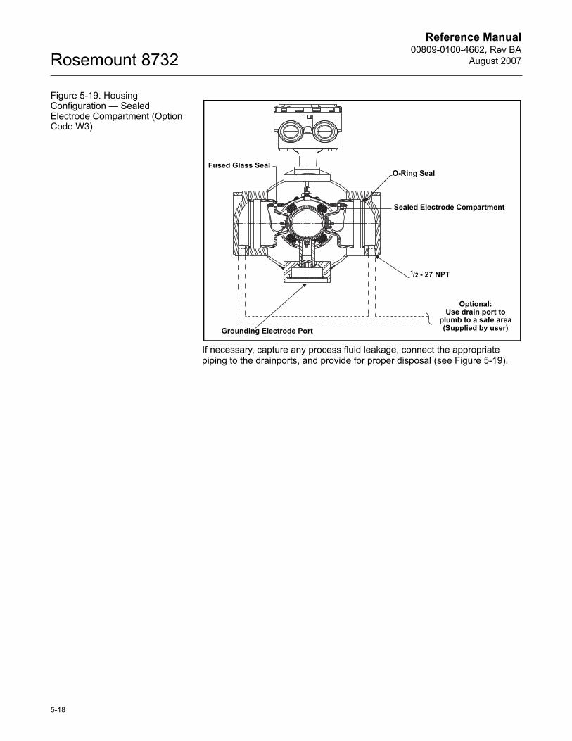
Reference Manual00809-0100-4662, Rev BA
August 2007Rosemount 8732
Figure 5-19. Housing Configuration — Sealed Electrode Compartment (Option Code W3)
If necessary, capture any process fluid leakage, connect the appropriate piping to the drainports, and provide for proper disposal (see Figure 5-19).
Fused Glass Seal
Sealed Electrode Compartment
1/2 - 27 NPT
O-Ring Seal
Optional:Use drain port to
plumb to a safe area (Supplied by user)Grounding Electrode Port
5-18
Reference Manual 00809-0100-4662, Rev BA
August 2007 Rosemount 8732
Section 6 Maintenance and Troubleshooting
Safety Information . . . . . . . . . . . . . . . . . . . . . . . . . . . . . . . page 6-1
Installation Check and Guide . . . . . . . . . . . . . . . . . . . . . . page 6-2
Diagnostic Messages . . . . . . . . . . . . . . . . . . . . . . . . . . . . . page 6-3
Transmitter Troubleshooting . . . . . . . . . . . . . . . . . . . . . . . page 6-7
Quick Troubleshooting . . . . . . . . . . . . . . . . . . . . . . . . . . . . page 6-9
This section covers basic transmitter and flowtube sensor troubleshooting. Problems in the magnetic flowmeter system are usually indicated by incorrect output readings from the system, error messages, or failed tests. Consider all sources when identifying a problem in your system. If the problem persists, consult your local Rosemount representative to determine if the material should be returned to the factory. Emerson Process Management offers several diagnostics that aid in the troubleshooting process.
Instructions and procedures in this section may require special precautions to ensure the safety of the personnel performing the operations. Please read the following safety messages before performing any operation described in this section. Refer to these warnings when appropriate throughout this section.
SAFETY INFORMATION
The 8732E performs self diagnostics on the entire magnetic flowmeter system: the transmitter, the flowtube, and the interconnecting wiring. By sequentially troubleshooting each individual piece of the magmeter system, it becomes easier to pin point the problem and make the appropriate adjustments.
If there are problems with a new magmeter installation, see “Installation Check and Guide” on page 6-2 for a quick guide to solve the most common installation problems. For existing magmeter installations, Table 6-5 lists the most common magmeter problems and corrective actions.
Failure to follow these installation guidelines could result in death or serious injury:
Installation and servicing instructions are for use by qualified personnel only. Do not perform
any servicing other than that contained in the operating instructions, unless qualified. Verify
that the operating environment of the flowtube and transmitter is consistent with the
appropriate FM or CSA approval.
Do not connect a Rosemount 8732E to a non-Rosemount flowtube that is located in an
explosive atmosphere.
Mishandling products exposed to a hazardous substance may result in death or serious
injury. If the product being returned was exposed to a hazardous substance as defined by
OSHA, a copy of the required Material Safety Data Sheet (MSDA) for each hazardous
substance identified must be included with the returned goods.
www.rosemount.com
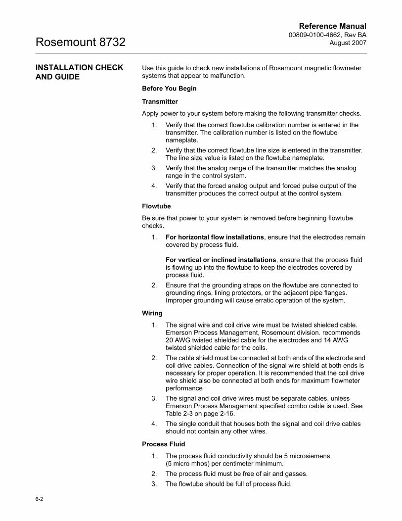
Reference Manual00809-0100-4662, Rev BA
August 2007Rosemount 8732
6-2
INSTALLATION CHECK AND GUIDE
Use this guide to check new installations of Rosemount magnetic flowmeter systems that appear to malfunction.
Before You Begin
Transmitter
Apply power to your system before making the following transmitter checks.
1. Verify that the correct flowtube calibration number is entered in the transmitter. The calibration number is listed on the flowtube nameplate.
2. Verify that the correct flowtube line size is entered in the transmitter. The line size value is listed on the flowtube nameplate.
3. Verify that the analog range of the transmitter matches the analog range in the control system.
4. Verify that the forced analog output and forced pulse output of the transmitter produces the correct output at the control system.
Flowtube
Be sure that power to your system is removed before beginning flowtube checks.
1. For horizontal flow installations, ensure that the electrodes remain covered by process fluid.
For vertical or inclined installations, ensure that the process fluid is flowing up into the flowtube to keep the electrodes covered by process fluid.
2. Ensure that the grounding straps on the flowtube are connected to grounding rings, lining protectors, or the adjacent pipe flanges. Improper grounding will cause erratic operation of the system.
Wiring
1. The signal wire and coil drive wire must be twisted shielded cable. Emerson Process Management, Rosemount division. recommends 20 AWG twisted shielded cable for the electrodes and 14 AWG twisted shielded cable for the coils.
2. The cable shield must be connected at both ends of the electrode and coil drive cables. Connection of the signal wire shield at both ends is necessary for proper operation. It is recommended that the coil drive wire shield also be connected at both ends for maximum flowmeter performance
3. The signal and coil drive wires must be separate cables, unless Emerson Process Management specified combo cable is used. See Table 2-3 on page 2-16.
4. The single conduit that houses both the signal and coil drive cables should not contain any other wires.
Process Fluid
1. The process fluid conductivity should be 5 microsiemens (5 micro mhos) per centimeter minimum.
2. The process fluid must be free of air and gasses.
3. The flowtube should be full of process fluid.
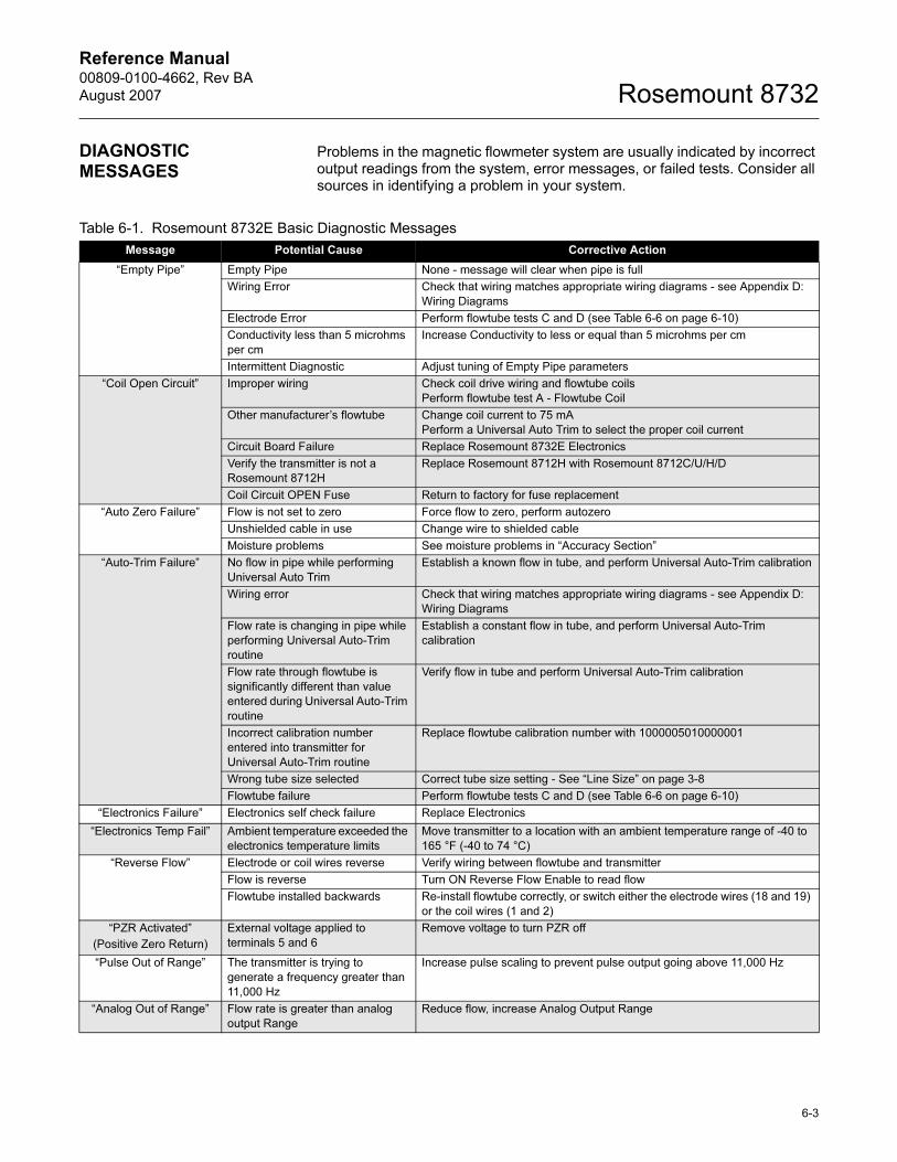
Reference Manual 00809-0100-4662, Rev BA
August 2007 Rosemount 8732
DIAGNOSTIC MESSAGES
Problems in the magnetic flowmeter system are usually indicated by incorrect output readings from the system, error messages, or failed tests. Consider all sources in identifying a problem in your system.
Table 6-1. Rosemount 8732E Basic Diagnostic Messages
Message Potential Cause Corrective Action
“Empty Pipe” Empty Pipe None - message will clear when pipe is full
Wiring Error Check that wiring matches appropriate wiring diagrams - see Appendix D:
Wiring Diagrams
Electrode Error Perform flowtube tests C and D (see Table 6-6 on page 6-10)
Conductivity less than 5 microhms
per cm
Increase Conductivity to less or equal than 5 microhms per cm
Intermittent Diagnostic Adjust tuning of Empty Pipe parameters
“Coil Open Circuit” Improper wiring Check coil drive wiring and flowtube coils
Perform flowtube test A - Flowtube Coil
Other manufacturer’s flowtube Change coil current to 75 mA
Perform a Universal Auto Trim to select the proper coil current
Circuit Board Failure Replace Rosemount 8732E Electronics
Verify the transmitter is not a
Rosemount 8712H
Replace Rosemount 8712H with Rosemount 8712C/U/H/D
Coil Circuit OPEN Fuse Return to factory for fuse replacement
“Auto Zero Failure” Flow is not set to zero Force flow to zero, perform autozero
Unshielded cable in use Change wire to shielded cable
Moisture problems See moisture problems in “Accuracy Section”
“Auto-Trim Failure” No flow in pipe while performing
Universal Auto Trim
Establish a known flow in tube, and perform Universal Auto-Trim calibration
Wiring error Check that wiring matches appropriate wiring diagrams - see Appendix D:
Wiring Diagrams
Flow rate is changing in pipe while
performing Universal Auto-Trim
routine
Establish a constant flow in tube, and perform Universal Auto-Trim
calibration
Flow rate through flowtube is
significantly different than value
entered during Universal Auto-Trim
routine
Verify flow in tube and perform Universal Auto-Trim calibration
Incorrect calibration number
entered into transmitter for
Universal Auto-Trim routine
Replace flowtube calibration number with 1000005010000001
Wrong tube size selected Correct tube size setting - See “Line Size” on page 3-8
Flowtube failure Perform flowtube tests C and D (see Table 6-6 on page 6-10)
“Electronics Failure” Electronics self check failure Replace Electronics
“Electronics Temp Fail” Ambient temperature exceeded the
electronics temperature limits
Move transmitter to a location with an ambient temperature range of -40 to
165 °F (-40 to 74 °C)
“Reverse Flow” Electrode or coil wires reverse Verify wiring between flowtube and transmitter
Flow is reverse Turn ON Reverse Flow Enable to read flow
Flowtube installed backwards Re-install flowtube correctly, or switch either the electrode wires (18 and 19)
or the coil wires (1 and 2)
“PZR Activated”
(Positive Zero Return)
External voltage applied to
terminals 5 and 6
Remove voltage to turn PZR off
“Pulse Out of Range” The transmitter is trying to
generate a frequency greater than
11,000 Hz
Increase pulse scaling to prevent pulse output going above 11,000 Hz
“Analog Out of Range” Flow rate is greater than analog
output Range
Reduce flow, increase Analog Output Range
6-3

Reference Manual00809-0100-4662, Rev BA
August 2007Rosemount 8732
Table 6-2. Rosemount 8732E Advanced Diagnostic Messages (Suite 1 - Option Code DA1)
“Flowrate > 43 ft/sec” Flow rate is greater than 43 ft/sec Lower flow velocity, increase pipe diameter
Improper wiring Check coil drive wiring and flowtube coils
Perform flowtube test A - Flowtube Coil (see Table 6-6 on page 6-10)
“Digital Trim Failure”
(Cycle power to clear
messages, no changes
were made)
The calibrator (8714B/C/D) is not
connected properly
Review calibrator connections
Incorrect calibration number
entered into transmitter
Replace flowtube calibration number with 1000005010000001
Calibrator is not set to 30 FPS Change calibrator setting to 30 FPS
Bad calibrator Replace calibrator
Message Potential Cause Corrective Action
Grounding/Wiring Fault Improper installation of wiring See “Flowtube Sensor Connections” on page 2-16
Coil/Electrode shield not
connected
See “Flowtube Sensor Connections” on page 2-16
Improper process grounding See “Grounding” on page 5-12
Faulty ground connection Check wiring for corrosion, moisture in the terminal block, and refer to
“Grounding” on page 5-12
Flowtube sensor not full Verify flowtube sensor is full
High Process Noise Slurry flows - mining/pulp stock Decrease the flow rate below 10 ft/s (3 m/s)
Complete the possible solutions listed under “Step 2: Process Noise” on
page 6-9
Chemical additives upstream of the
flowtube sensor
Move injection point downstream of the flowtube sensor, or move the
flowtube sensor
Complete the possible solutions listed under “Step 2: Process Noise” on
page 6-9
Electrode not compatible with the
process fluid
Refer to the Rosemount Magnetic Flowmeter Material Selection Guide
(00816-0100-3033)
Air in line Move the flowtube sensor to another location in the process line to ensure
that it is full under all conditions
Electrode coating Use bulletnose electrodes
Downsize flowtube sensor to increases flowrate above 3 ft/s (1 m/s)
Periodically clean flowtube sensor
Styrofoam or other insulating
particles
Complete the possible solutions listed under “Step 2: Process Noise” on
page 6-9
Consult factory
Low conductivity fluids
(below 10 microsiemens/cm)
Trim electrode and coil wires - refer to “Cable Preparation Detail” on
page 2-17
Table 6-1. Rosemount 8732E Basic Diagnostic Messages
Message Potential Cause Corrective Action
6-4
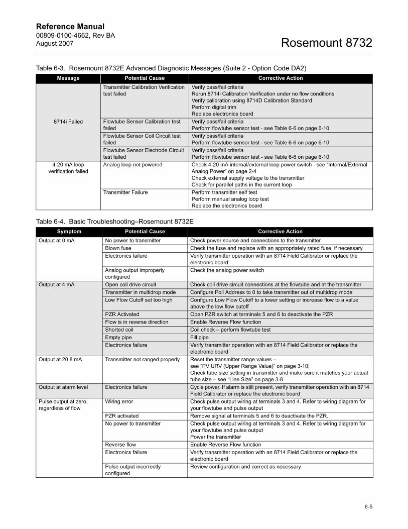
Reference Manual 00809-0100-4662, Rev BA
August 2007 Rosemount 8732
Table 6-3. Rosemount 8732E Advanced Diagnostic Messages (Suite 2 - Option Code DA2)
Message Potential Cause Corrective Action
8714i Failed
Transmitter Calibration Verification
test failed
Verify pass/fail criteria
Rerun 8714i Calibration Verification under no flow conditions
Verify calibration using 8714D Calibration Standard
Perform digital trim
Replace electronics board
Flowtube Sensor Calibration test
failed
Verify pass/fail criteria
Perform flowtube sensor test - see Table 6-6 on page 6-10
Flowtube Sensor Coil Circuit test
failed
Verify pass/fail criteria
Perform flowtube sensor test - see Table 6-6 on page 6-10
Flowtube Sensor Electrode Circuit
test failed
Verify pass/fail criteria
Perform flowtube sensor test - see Table 6-6 on page 6-10
4-20 mA loop
verification failed
Analog loop not powered Check 4-20 mA internal/external loop power switch - see “Internal/External
Analog Power” on page 2-4
Check external supply voltage to the transmitter
Check for parallel paths in the current loop
Transmitter Failure Perform transmitter self test
Perform manual analog loop test
Replace the electronics board
Table 6-4. Basic Troubleshooting–Rosemount 8732E
Symptom Potential Cause Corrective Action
Output at 0 mA No power to transmitter Check power source and connections to the transmitter
Blown fuse Check the fuse and replace with an appropriately rated fuse, if necessary
Electronics failure Verify transmitter operation with an 8714 Field Calibrator or replace the
electronic board
Analog output improperly
configured
Check the analog power switch
Output at 4 mA Open coil drive circuit Check coil drive circuit connections at the flowtube and at the transmitter
Transmitter in multidrop mode Configure Poll Address to 0 to take transmitter out of multidrop mode
Low Flow Cutoff set too high Configure Low Flow Cutoff to a lower setting or increase flow to a value
above the low flow cutoff
PZR Activated Open PZR switch at terminals 5 and 6 to deactivate the PZR
Flow is in reverse direction Enable Reverse Flow function
Shorted coil Coil check – perform flowtube test
Empty pipe Fill pipe
Electronics failure Verify transmitter operation with an 8714 Field Calibrator or replace the
electronic board
Output at 20.8 mA Transmitter not ranged properly Reset the transmitter range values –
see “PV URV (Upper Range Value)” on page 3-10;
Check tube size setting in transmitter and make sure it matches your actual
tube size – see “Line Size” on page 3-8
Output at alarm level Electronics failure Cycle power. If alarm is still present, verify transmitter operation with an 8714
Field Calibrator or replace the electronic board
Pulse output at zero,
regardless of flow
Wiring error Check pulse output wiring at terminals 3 and 4. Refer to wiring diagram for
your flowtube and pulse output
PZR activated Remove signal at terminals 5 and 6 to deactivate the PZR.
No power to transmitter Check pulse output wiring at terminals 3 and 4. Refer to wiring diagram for
your flowtube and pulse output
Power the transmitter
Reverse flow Enable Reverse Flow function
Electronics failure Verify transmitter operation with an 8714 Field Calibrator or replace the
electronic board
Pulse output incorrectly
configured
Review configuration and correct as necessary
6-5
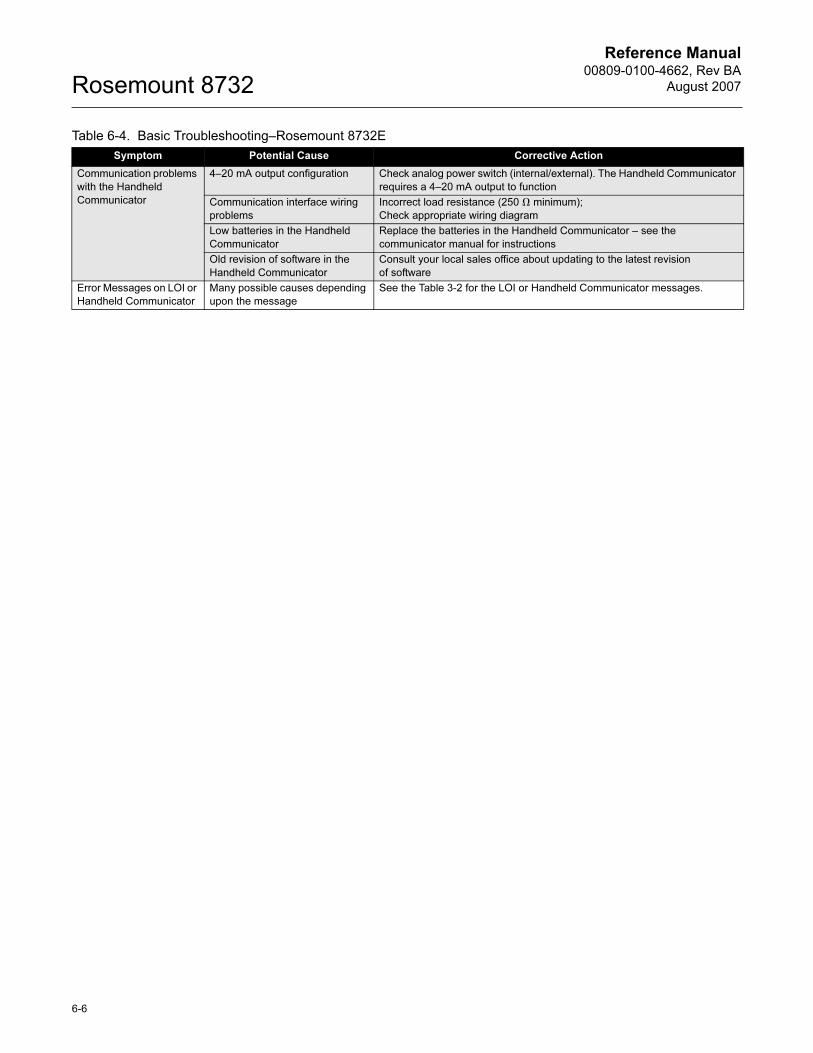
Reference Manual00809-0100-4662, Rev BA
August 2007Rosemount 8732
Communication problems
with the Handheld
Communicator
4–20 mA output configuration Check analog power switch (internal/external). The Handheld Communicator
requires a 4–20 mA output to function
Communication interface wiring
problems
Incorrect load resistance (250 � minimum);
Check appropriate wiring diagram
Low batteries in the Handheld
Communicator
Replace the batteries in the Handheld Communicator – see the
communicator manual for instructions
Old revision of software in the
Handheld Communicator
Consult your local sales office about updating to the latest revision
of software
Error Messages on LOI or
Handheld Communicator
Many possible causes depending
upon the message
See the Table 3-2 for the LOI or Handheld Communicator messages.
Table 6-4. Basic Troubleshooting–Rosemount 8732E
Symptom Potential Cause Corrective Action
6-6
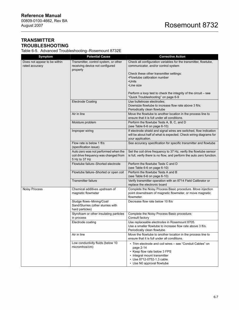
Reference Manual 00809-0100-4662, Rev BA
August 2007 Rosemount 8732
TRANSMITTER TROUBLESHOOTINGTable 6-5. Advanced Troubleshooting–Rosemount 8732E
Symptom Potential Cause Corrective Action
Does not appear to be within
rated accuracy
Transmitter, control system, or other
receiving device not configured
properly
Check all configuration variables for the transmitter, flowtube,
communicator, and/or control system
Check these other transmitter settings:
•Flowtube calibration number
•Units
•Line size
Perform a loop test to check the integrity of the circuit – see
“Quick Troubleshooting” on page 6-9
Electrode Coating Use bulletnose electrodes;
Downsize flowtube to increase flow rate above 3 ft/s;
Periodically clean flowtube
Air in line Move the flowtube to another location in the process line to
ensure that it is full under all conditions.
Moisture problem Perform the flowtube Tests A, B, C, and D
(see Table 6-6 on page 6-10)
Improper wiring If electrode shield and signal wires are switched, flow indication
will be about half of what is expected. Check wiring diagrams for
your application.
Flow rate is below 1 ft/s
(specification issue)
See accuracy specification for specific transmitter and flowtube
Auto zero was not performed when the
coil drive frequency was changed from
5 Hz to 37 Hz
Set the coil drive frequency to 37 Hz, verify the flowtube sensor
is full, verify there is no flow, and perform the auto zero function.
Flowtube failure–Shorted electrode Perform the flowtube Tests C and D
(see Table 6-6 on page 6-10)
Flowtube failure–Shorted or open coil Perform the flowtube Tests A and B
(see Table 6-6 on page 6-10)
Transmitter failure Verify transmitter operation with an 8714 Field Calibrator or
replace the electronic board
Noisy Process Chemical additives upstream of
magnetic flowmeter
Complete the Noisy Process Basic procedure. Move injection
point downstream of magnetic flowmeter, or move magnetic
flowmeter.
Sludge flows–Mining/Coal/
Sand/Slurries (other slurries with
hard particles)
Decrease flow rate below 10 ft/s
Styrofoam or other insulating particles
in process
Complete the Noisy Process Basic procedure;
Consult factory
Electrode coating Use replaceable electrodes in Rosemount 8705.
Use a smaller flowtube to increase flow rate above 3 ft/s.
Periodically clean flowtube.
Air in line Move the flowtube to another location in the process line to
ensure that it is full under all conditions.
Low conductivity fluids (below 10
micromhos/cm)• Trim electrode and coil wires – see “Conduit Cables” on
page 2-14
• Keep flow rate below 3 FPS
• Integral mount transmitter
• Use 8712-0752-1,3 cable
• Use N0 approval flowtube
6-7
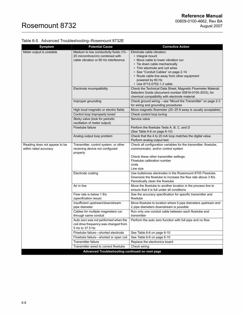
Reference Manual00809-0100-4662, Rev BA
August 2007Rosemount 8732
Meter output is unstable Medium to low conductivity fluids (10–
25 micromhos/cm) combined with
cable vibration or 60 Hz interference
Eliminate cable vibration:
• Integral mount
• Move cable to lower vibration run
• Tie down cable mechanically
• Trim electrode and coil wires
• See “Conduit Cables” on page 2-14
• Route cable line away from other equipment
powered by 60 Hz
• Use 8712-0752-1,3 cable
Electrode incompatibility Check the Technical Data Sheet, Magnetic Flowmeter Material
Selection Guide (document number 00816-0100-3033), for
chemical compatibility with electrode material.
Improper grounding Check ground wiring – see “Mount the Transmitter” on page 2-3
for wiring and grounding procedures
High local magnetic or electric fields Move magnetic flowmeter (20–25 ft away is usually acceptable)
Control loop improperly tuned Check control loop tuning
Sticky valve (look for periodic
oscillation of meter output)
Service valve
Flowtube failure Perform the flowtube Tests A, B, C, and D
(See Table 6-6 on page 6-10)
Analog output loop problem Check that the 4 to 20 mA loop matches the digital value.
Perform analog output test.
Reading does not appear to be
within rated accuracy
Transmitter, control system, or other
receiving device not configured
properly
Check all configuration variables for the transmitter, flowtube,
communicator, and/or control system
Check these other transmitter settings:
Flowtube calibration number
Units
Line size
Electrode coating Use bulletnose electrodes in the Rosemount 8705 Flowtube.
Downsize the flowtube to increase the flow rate above 3 ft/s.
Periodically clean the flowtube
Air in line Move the flowtube to another location in the process line to
ensure that it is full under all conditions
Flow rate is below 1 ft/s
(specification issue)
See the accuracy specification for specific transmitter and
flowtube
Insufficient upstream/downstream
pipe diameter
Move flowtube to location where 5 pipe diameters upstream and
2 pipe diameters downstream is possible
Cables for multiple magmeters run
through same conduit
Run only one conduit cable between each flowtube and
transmitter
Auto zero was not performed when the
coil drive frequency was changed from
5 Hz to 37.5 Hz
Perform the auto zero function with full pipe and no flow
Flowtube failure—shorted electrode See Table 6-6 on page 6-10
Flowtube failure—shorted or open coil See Table 6-6 on page 6-10
Transmitter failure Replace the electronics board
Transmitter wired to correct flowtube Check wiring
Advanced Troubleshooting continued on next page
Table 6-5. Advanced Troubleshooting–Rosemount 8732E
Symptom Potential Cause Corrective Action
6-8
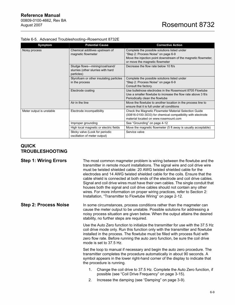
Reference Manual 00809-0100-4662, Rev BA
August 2007 Rosemount 8732
QUICK TROUBLESHOOTING
Step 1: Wiring Errors The most common magmeter problem is wiring between the flowtube and the transmitter in remote mount installations. The signal wire and coil drive wire must be twisted shielded cable: 20 AWG twisted shielded cable for the electrodes and 14 AWG twisted shielded cable for the coils. Ensure that the cable shield is connected at both ends of the electrode and coil drive cables. Signal and coil drive wires must have their own cables. The single conduit that houses both the signal and coil drive cables should not contain any other wires. For more information on proper wiring practices, refer to Section 2: Installation, “Transmitter to Flowtube Wiring” on page 2-12.
Step 2: Process Noise In some circumstances, process conditions rather than the magmeter can cause the meter output to be unstable. Possible solutions for addressing a noisy process situation are given below. When the output attains the desired stability, no further steps are required.
Use the Auto Zero function to initialize the transmitter for use with the 37.5 Hz coil drive mode only. Run this function only with the transmitter and flowtube installed in the process. The flowtube must be filled with process fluid with zero flow rate. Before running the auto zero function, be sure the coil drive mode is set to 37.5 Hz.
Set the loop to manual if necessary and begin the auto zero procedure. The transmitter completes the procedure automatically in about 90 seconds. A symbol appears in the lower right-hand corner of the display to indicate that the procedure is running.
1. Change the coil drive to 37.5 Hz. Complete the Auto Zero function, if possible (see “Coil Drive Frequency” on page 3-15).
2. Increase the damping (see “Damping” on page 3-9).
Noisy process Chemical additives upstream of
magnetic flowmeter
Complete the possible solutions listed under
“Step 2: Process Noise” on page 6-9
Move the injection point downstream of the magnetic flowmeter,
or move the magnetic flowmeter
Sludge flows—mining/coal/sand/
slurries (other slurries with hard
particles)
Decrease the flow rate below 10 ft/s
Styrofoam or other insulating particles
in the process
Complete the possible solutions listed under
“Step 2: Process Noise” on page 6-9
Consult the factory.
Electrode coating Use bulletnose electrodes in the Rosemount 8705 Flowtube
Use a smaller flowtube to increase the flow rate above 3 ft/s
Periodically clean the flowtube
Air in the line Move the flowtube to another location in the process line to
ensure that it is full under all conditions
Meter output is unstable Electrode incompatibility Check the Magnetic Flowmeter Material Selection Guide
(00816-0100-3033) for chemical compatibility with electrode
material located on www.rosemount.com
Improper grounding See “Grounding” on page 4-12
High local magnetic or electric fields Move the magnetic flowmeter (5 ft away is usually acceptable)
Sticky valve (Look for periodic
oscillation of meter output)
Service valve
Table 6-5. Advanced Troubleshooting–Rosemount 8732E
Symptom Potential Cause Corrective Action
6-9
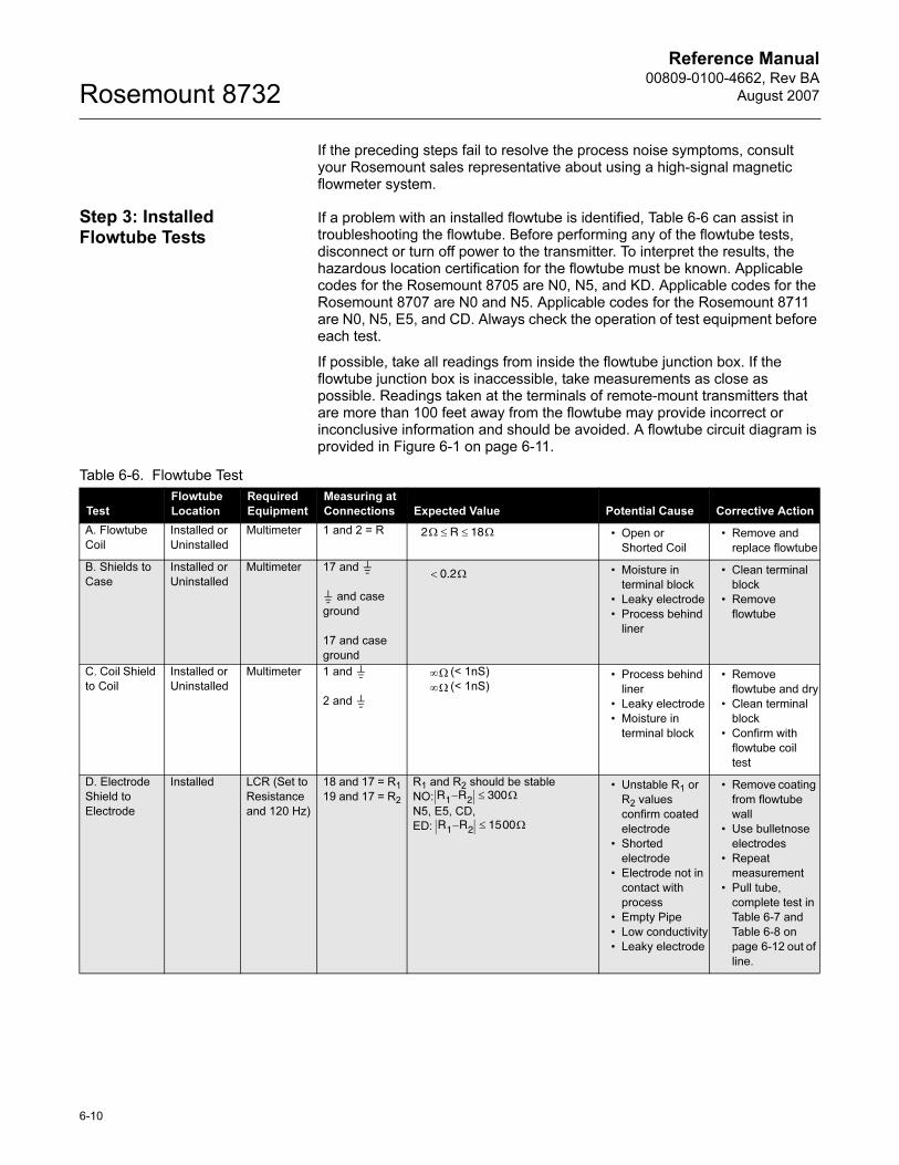
Reference Manual00809-0100-4662, Rev BA
August 2007Rosemount 8732
If the preceding steps fail to resolve the process noise symptoms, consult your Rosemount sales representative about using a high-signal magnetic flowmeter system.
Step 3: Installed Flowtube Tests
If a problem with an installed flowtube is identified, Table 6-6 can assist in troubleshooting the flowtube. Before performing any of the flowtube tests, disconnect or turn off power to the transmitter. To interpret the results, the hazardous location certification for the flowtube must be known. Applicable codes for the Rosemount 8705 are N0, N5, and KD. Applicable codes for the Rosemount 8707 are N0 and N5. Applicable codes for the Rosemount 8711 are N0, N5, E5, and CD. Always check the operation of test equipment before each test.
If possible, take all readings from inside the flowtube junction box. If the flowtube junction box is inaccessible, take measurements as close as possible. Readings taken at the terminals of remote-mount transmitters that are more than 100 feet away from the flowtube may provide incorrect or inconclusive information and should be avoided. A flowtube circuit diagram is provided in Figure 6-1 on page 6-11.
Table 6-6. Flowtube Test
Test
Flowtube
Location
Required
Equipment
Measuring at
Connections Expected Value Potential Cause Corrective Action
A. Flowtube
Coil
Installed or
Uninstalled
Multimeter 1 and 2 = R • Open or
Shorted Coil
• Remove and
replace flowtube
B. Shields to
Case
Installed or
Uninstalled
Multimeter 17 and
and case
ground
17 and case
ground
• Moisture in
terminal block
• Leaky electrode
• Process behind
liner
• Clean terminal
block
• Remove
flowtube
C. Coil Shield
to Coil
Installed or
Uninstalled
Multimeter 1 and
2 and
(< 1nS)
(< 1nS)• Process behind
liner
• Leaky electrode
• Moisture in
terminal block
• Remove
flowtube and dry
• Clean terminal
block
• Confirm with
flowtube coil
test
D. Electrode
Shield to
Electrode
Installed LCR (Set to
Resistance
and 120 Hz)
18 and 17 = R1
19 and 17 = R2
R1 and R2 should be stable
NO:
N5, E5, CD,
ED:
• Unstable R1 or
R2 values
confirm coated
electrode
• Shorted
electrode
• Electrode not in
contact with
process
• Empty Pipe
• Low conductivity
• Leaky electrode
• Remove coating
from flowtube
wall
• Use bulletnose
electrodes
• Repeat
measurement
• Pull tube,
complete test in
Table 6-7 and
Table 6-8 on
page 6-12 out of
line.
2Ω R 18Ω≤ ≤
0.2Ω<
∞Ω
∞Ω
R1 R– 2 300Ω≤
R1 R– 2 1500Ω≤
6-10
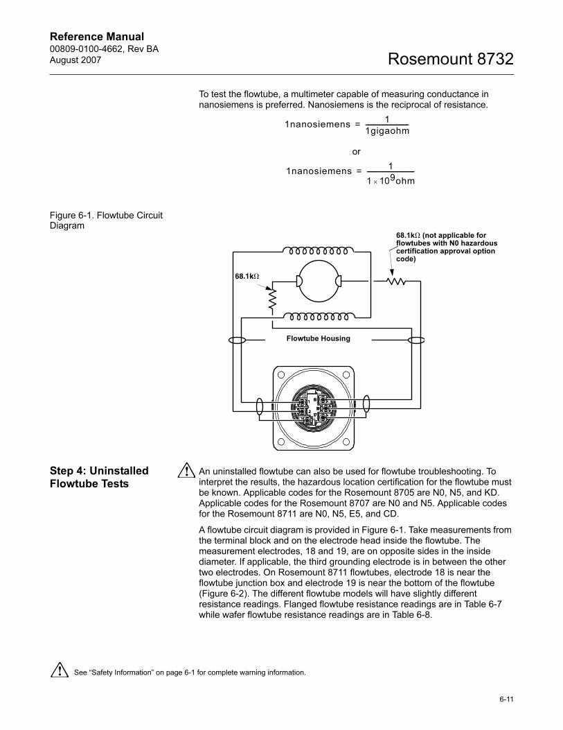
Reference Manual 00809-0100-4662, Rev BA
August 2007 Rosemount 8732
To test the flowtube, a multimeter capable of measuring conductance in nanosiemens is preferred. Nanosiemens is the reciprocal of resistance.
or
Figure 6-1. Flowtube Circuit Diagram
Step 4: Uninstalled Flowtube Tests
An uninstalled flowtube can also be used for flowtube troubleshooting. To interpret the results, the hazardous location certification for the flowtube must be known. Applicable codes for the Rosemount 8705 are N0, N5, and KD. Applicable codes for the Rosemount 8707 are N0 and N5. Applicable codes for the Rosemount 8711 are N0, N5, E5, and CD.
A flowtube circuit diagram is provided in Figure 6-1. Take measurements from the terminal block and on the electrode head inside the flowtube. The measurement electrodes, 18 and 19, are on opposite sides in the inside diameter. If applicable, the third grounding electrode is in between the other two electrodes. On Rosemount 8711 flowtubes, electrode 18 is near the flowtube junction box and electrode 19 is near the bottom of the flowtube (Figure 6-2). The different flowtube models will have slightly different resistance readings. Flanged flowtube resistance readings are in Table 6-7 while wafer flowtube resistance readings are in Table 6-8.
1nanosiemens1
1gigaohm----------------------------=
1nanosiemens1
1 109ohm×
-------------------------------=
68.1k� (not applicable for flowtubes with N0 hazardous certification approval option code)
Flowtube Housing
68.1k�
See “Safety Information” on page 6-1 for complete warning information.
6-11
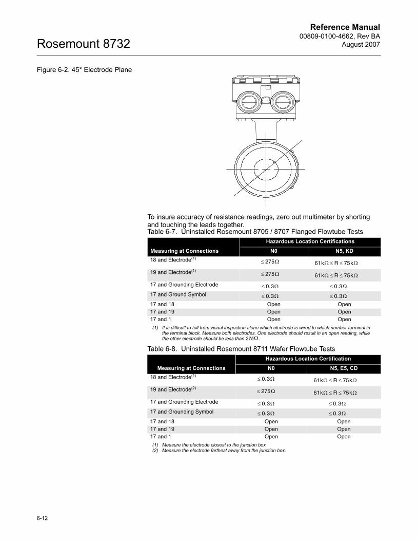
Reference Manual00809-0100-4662, Rev BA
August 2007Rosemount 8732
Figure 6-2. 45° Electrode Plane
To insure accuracy of resistance readings, zero out multimeter by shorting and touching the leads together. Table 6-7. Uninstalled Rosemount 8705 / 8707 Flanged Flowtube Tests
Measuring at Connections
Hazardous Location Certifications
N0 N5, KD
18 and Electrode(1)
(1) It is difficult to tell from visual inspection alone which electrode is wired to which number terminal in the terminal block. Measure both electrodes. One electrode should result in an open reading, while the other electrode should be less than 275 .
19 and Electrode(1)
17 and Grounding Electrode
17 and Ground Symbol
17 and 18 Open Open
17 and 19 Open Open
17 and 1 Open Open
Table 6-8. Uninstalled Rosemount 8711 Wafer Flowtube Tests
Measuring at Connections
Hazardous Location Certification
N0 N5, E5, CD
18 and Electrode(1)
(1) Measure the electrode closest to the junction box
19 and Electrode(2)
(2) Measure the electrode farthest away from the junction box.
17 and Grounding Electrode
17 and Grounding Symbol
17 and 18 Open Open
17 and 19 Open Open
17 and 1 Open Open
Ω
275≤ Ω 61kΩ R 75k≤ ≤ Ω
275≤ Ω 61kΩ R 75k≤ ≤ Ω
0.3≤ Ω 0.3≤ Ω
0.3≤ Ω 0.3≤ Ω
0.3≤ Ω 61kΩ R 75k≤ ≤ Ω
275≤ Ω 61kΩ R 75k≤ ≤ Ω
0.3≤ Ω 0.3≤ Ω
0.3≤ Ω 0.3≤ Ω
6-12
Reference Manual 00809-0100-4662, Rev BA
August 2007 Rosemount 8732
Appendix A Reference Data
Dimensional Drawings . . . . . . . . . . . . . . . . . . . . . . . . . . . . page A-31
Magnetic Flowmeter Sizing . . . . . . . . . . . . . . . . . . . . . . . . page A-40
Product Selection Guide . . . . . . . . . . . . . . . . . . . . . . . . . . page A-43
Ordering Information . . . . . . . . . . . . . . . . . . . . . . . . . . . . . page A-48
Rosemount 8732E Ordering Information . . . . . . . . . . . . . page A-48
Rosemount 8712D Ordering Information . . . . . . . . . . . . . page A-50
Rosemount 8712H Ordering Information . . . . . . . . . . . . . page A-51
Rosemount 8742C Ordering Information . . . . . . . . . . . . . page A-52
ROSEMOUNT 8732E TRANSMITTER SPECIFICATIONS
Functional Specifications
Flowtube Sensor Compatibility
Compatible with Rosemount 8705, 8711, 8721, and 570TM flowtube sensors.
Compatible with Rosemount 8707 flowtube sensor with D2 Dual Calibration Option.
Compatible with AC and DC powered flowtube sensors of other manufacturers.
Flowtube Sensor Coil Resistance
25 Ω maximum
Flow Rate Range
Capable of processing signals from fluids that are traveling between 0.04 and 40 ft/s (0.01 to 12 m/s) for both forward and reverse flow in all flowtube sensor sizes. Full scale continuously adjustable between –40 and 40 ft/s (–12 to 12 m/s).
Conductivity Limits
Process liquid must have a conductivity of 5 microsiemens/cm (5 micromhos/cm) or greater for 8732E. Excludes the effect of interconnecting cable length in remote mount transmitter installations.
Power Supply
90 -250 V AC ±10%, 50–60 Hz or 12-42 V DC
www.rosemount.com
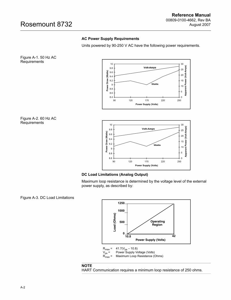
Reference Manual00809-0100-4662, Rev BA
August 2007Rosemount 8732
AC Power Supply Requirements
Units powered by 90-250 V AC have the following power requirements.
Figure A-1. 50 Hz AC Requirements
Figure A-2. 60 Hz AC Requirements
DC Load Limitations (Analog Output)
Maximum loop resistance is determined by the voltage level of the external power supply, as described by:
Figure A-3. DC Load Limitations
NOTEHART Communication requires a minimum loop resistance of 250 ohms.
8.4
8.6
8.8
9
9.2
9.4
9.6
9.8
10
90 120 170 220 250
Power Supply (Volts)Po
wer
Dra
w (W
atts
)
0
5
10
15
20
25
30
App
aren
t Pow
er (V
olt-A
mps
)
8.6
8.8
9
9.2
9.4
9.6
9.8
10
90 120 170 220 250
Power Supply (Volts)
Pow
er D
raw
(Wat
ts)
0
5
10
15
20
25
30
App
aren
t Pow
er (V
olt-A
mps
)
Rmax = 41.7(Vps – 10.8)
Vps = Power Supply Voltage (Volts)
Rmax = Maximum Loop Resistance (Ohms)
Power Supply (Volts)
Lo
ad (
Oh
ms)
OperatingRegion
1250
1000
500
010.8 42
A-2
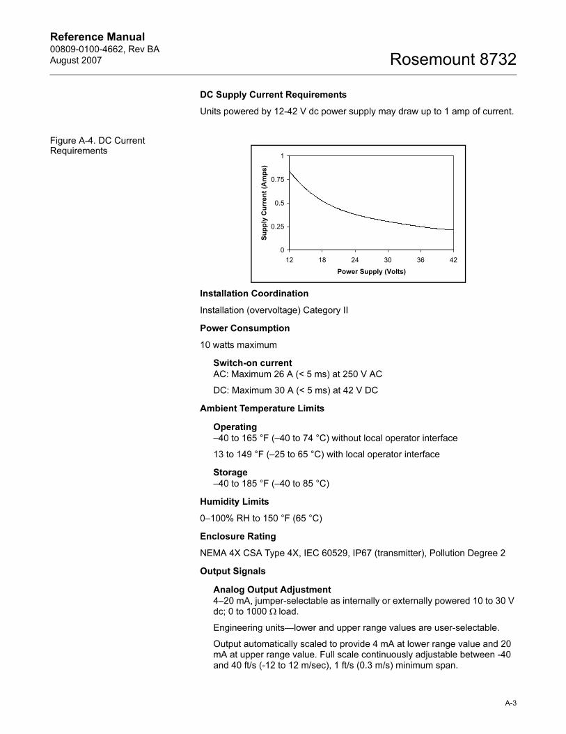
Reference Manual 00809-0100-4662, Rev BA
August 2007 Rosemount 8732
DC Supply Current Requirements
Units powered by 12-42 V dc power supply may draw up to 1 amp of current.
Figure A-4. DC Current Requirements
Installation Coordination
Installation (overvoltage) Category II
Power Consumption
10 watts maximum
Switch-on currentAC: Maximum 26 A (< 5 ms) at 250 V AC
DC: Maximum 30 A (< 5 ms) at 42 V DC
Ambient Temperature Limits
Operating–40 to 165 °F (–40 to 74 °C) without local operator interface
13 to 149 °F (–25 to 65 °C) with local operator interface
Storage–40 to 185 °F (–40 to 85 °C)
Humidity Limits
0–100% RH to 150 °F (65 °C)
Enclosure Rating
NEMA 4X CSA Type 4X, IEC 60529, IP67 (transmitter), Pollution Degree 2
Output Signals
Analog Output Adjustment4–20 mA, jumper-selectable as internally or externally powered 10 to 30 V dc; 0 to 1000 Ω load.
Engineering units—lower and upper range values are user-selectable.
Output automatically scaled to provide 4 mA at lower range value and 20 mA at upper range value. Full scale continuously adjustable between -40 and 40 ft/s (-12 to 12 m/sec), 1 ft/s (0.3 m/s) minimum span.
0
0.25
0.5
0.75
1
12 18 24 30 36 42
Power Supply (Volts)Su
pply
Cur
rent
(Am
ps)
A-3
Reference Manual00809-0100-4662, Rev BA
August 2007Rosemount 8732
HART Communications, digital flow signal, superimposed on 4–20 mA signal, available for control system interface. 250 Ω required for HART communications.
Scalable Frequency Adjustment
0-10,000 Hz, jumper-selectable as internally or externally powered 10 to 30 V dc, translator
switch closure up to 5.75 w. Pulse value can be set to equal desired volume in selected
engineering units. Pulse width adjustable from 0.5 to 100 m/s. Local operator interface
automatically calculates and displays maximum allowable output frequency.
Digital Output Function
Externally powered at 5 to 24 V dc, transistor switch closure up to 3 W to indicate either:
Reverse Flow: Activates switch closure output when reverse flow is detected. The reverse
flow rate is displayed.
Zero Flow: Activates switch closure output when flow goes to 0 ft/s.
Empty Pipe: Activates switch closure output when empty pipe is detected.
Transmitter Fault: Activates switch closure output when a transmitter fault is detected.
Digital Input Function
Externally powered at 5 to 24 V dc, transistor switch closure up to 3 W to indicate either:
Net Total Reset: Resets the net totalizer value to zero.
Positive Zero Return (PZR): Simulates zero-flow condition.
Software Lockout
Security lockout switch on the electronics board can be set to deactivate all LOI and HART-based
communicator functions to protect configuration variables from unwanted or accidental change.
Display Lockout
All optical switches on the display can be locked locally from the display layout configuration
screen by holding the upper right optical switch for 10 seconds. The display can be reactivated
holding the same switch for 10 seconds.
Output Testing
Analog Output Test
Transmitter may be commanded to supply a specified current between 3.5 and 23 mA.
Pulse Output Test
Transmitter may be commanded to supply a specified frequency between 1 and 10,000 Hz.
Turn-on Time
5 minutes to rated accuracy from power up; 5 seconds from power interruption.
Start-up Time
50 ms from zero flow.
Low Flow Cutoff
Adjustable between 0.01 and 38.37 ft/s (0.003 and 11.7 m/s). Below selected value, output is
driven to the zero flow rate signal level.
Overrange Capability
Signal output will remain linear until 110% of upper range value or 43 ft/s (13 m/s). The signal
output will remain constant above these values. Out of range message displayed on LOI and the
HART Communicator.
Damping
Adjustable between 0 and 256 seconds.
Flowtube Sensor Compensation
Rosemount flowtube sensors are flow-calibrated and assigned a calibration factor at the factory.
The calibration factor is entered into the transmitter, enabling interchangeability of flowtube
sensors without calculations or a compromise in accuracy.
A-4
Reference Manual 00809-0100-4662, Rev BA
August 2007 Rosemount 8732
A-5
8732E transmitters and other manufacturer’s flowtube sensors can be calibrated at known
process conditions or at the Rosemount NIST-Traceable Flow Facility. Transmitters calibrated on
site require a two-step procedure to match a known flow rate.
Diagnostics
Basic
Self test
Transmitter faults
Analog output test
Pulse output test
Tunable empty pipe
Reverse flow
Coil circuit fault
Electronics temperature
Advanced (DA1 Suite)
Ground/wiring fault
High process noise
4-20 mA loop verification
Advanced (DA2 Suite)
8714i Calibration Verification
4-20 mA loop verification
Performance Specifications
(System specifications are given using the frequency output and with the unit at reference
conditions.)
Accuracy(1)
Includes the combined effects of linearity, hysteresis, repeatability, and calibration uncertainty.
Rosemount 8732E with 8705/8707 Flowtube Sensor:
Standard system accuracy is ±0.25% of rate ±1.0 mm/sec from 0.04 to 6 ft/s (0.01 to 2 m/s);
above 6 ft/s (2 m/s), the system has an accuracy of ±0.25% of rate ±1.5 mm/sec.
Optional high accuracy is ±0.15% of rate ±1.0 mm/sec from 0.04 to 13 ft/s (0.01 to 4 m/s);
above 13 ft/s (4 m/s), the system has an accuracy of ±0.18% of rate.(2)
Rosemount 8732E with 8711 Flowtube Sensor:
Standard system accuracy is ±0.25% of rate ±2.0 mm/sec from 0.04 to 40 ft/s (0.01 to 12
m/s).
Optional high accuracy is ±0.15% of rate ±1.0 mm/sec from 0.04 to 13 ft/s (0.01 to 4 m/s);
above 13 ft/s (4 m/s), the system has an accuracy of ±0.18% of rate.
Rosemount 8732E with 8721 Flowtube Sensor:
Standard system accuracy is ±0.5% of rate from 1 to 40 ft/s (0.3 to 12 m/s); between 0.04 and
1.0 ft/s (0.01 and 0.3 m/s), the system has an accuracy of ±0.005 ft/s (0.0015 m/s).
Optional high accuracy is ±0.25% of rate from 3 to 40 ft/s (1 to 12 m/s).
Rosemount 8732E with Other Manufacturers’ Flowtube Sensors:
When calibrated in the Rosemount Flow Facility, system accuracies as good as 0.5% of rate
can be attained.
There is no accuracy specification for other manufacturers’ flowtube sensors calibrated in the
process line.
Analog Output Effect
Analog output has the same accuracy as frequency output plus an additional ±4μA.
Vibration Effect
IEC 60770-1
(1) Operating at Coil Drive Frequency of 37 Hz increases uncertainty by ±0.05% of rate.
(2) For Flowtube Sensor sizes greater than 12 in. (300 mm) the high accuracy is ±0.25% of rate
from 3 to 40 ft/sec (1 to 12 m/sec).
Reference Manual00809-0100-4662, Rev BA
August 2007Rosemount 8732
Repeatability
±0.1% of reading
Response Time (Analog Output)
50 ms maximum response to step change in input
Stability
±0.1% of rate over six months
Ambient Temperature Effect
±0.25% change over operating temperature range
EMC Compliance
EN61326-1 1997 + A1/A2 (Industrial) electromagnetic compatibility (EMC) for process and
laboratory apparatus.
Dead TimeAt 5 Hz, up to 100 ms
At 37 Hz, up to 13.3 ms
Physical Specifications Materials of Construction
Housing
Low copper aluminum, NEMA 4X and IEC 60529 IP66
Pollution Degree 2
Paint
Polyurethane
Cover Gasket
Rubber
Electrical Connections
Two 1/2–14 NPT connections provided on the transmitter housing (optional third connection
available). PG13.5 and CM20 adapters are available. Screw terminals provided for all
connections. Power wiring connected to transmitter only. Integrally mounted transmitters are
factory wired to the flowtube sensor.
Transmitter Weight
Approximately 7 pounds (3.2 kg). Add 1 pound (0.5 kg) for Option Code M4.
A-6
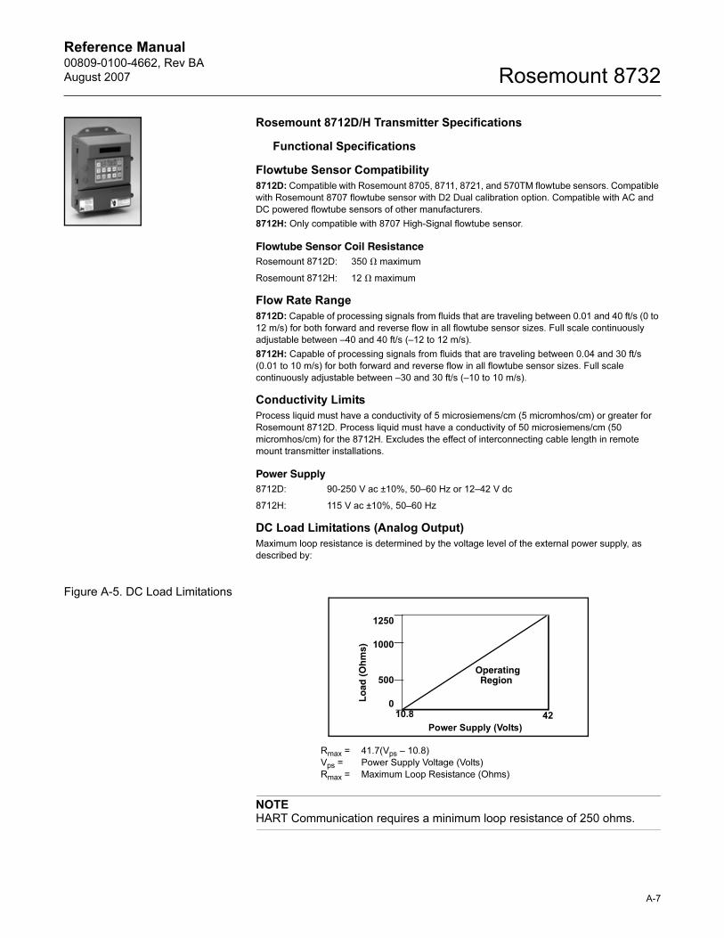
Reference Manual 00809-0100-4662, Rev BA
August 2007 Rosemount 8732
Rosemount 8712D/H Transmitter Specifications
Functional Specifications
Flowtube Sensor Compatibility
8712D: Compatible with Rosemount 8705, 8711, 8721, and 570TM flowtube sensors. Compatible
with Rosemount 8707 flowtube sensor with D2 Dual calibration option. Compatible with AC and
DC powered flowtube sensors of other manufacturers.
8712H: Only compatible with 8707 High-Signal flowtube sensor.
Flowtube Sensor Coil Resistance
Flow Rate Range
8712D: Capable of processing signals from fluids that are traveling between 0.01 and 40 ft/s (0 to
12 m/s) for both forward and reverse flow in all flowtube sensor sizes. Full scale continuously
adjustable between –40 and 40 ft/s (–12 to 12 m/s).
8712H: Capable of processing signals from fluids that are traveling between 0.04 and 30 ft/s
(0.01 to 10 m/s) for both forward and reverse flow in all flowtube sensor sizes. Full scale
continuously adjustable between –30 and 30 ft/s (–10 to 10 m/s).
Conductivity Limits
Process liquid must have a conductivity of 5 microsiemens/cm (5 micromhos/cm) or greater for
Rosemount 8712D. Process liquid must have a conductivity of 50 microsiemens/cm (50
micromhos/cm) for the 8712H. Excludes the effect of interconnecting cable length in remote
mount transmitter installations.
Power Supply
DC Load Limitations (Analog Output)
Maximum loop resistance is determined by the voltage level of the external power supply, as
described by:
Figure A-5. DC Load Limitations
NOTEHART Communication requires a minimum loop resistance of 250 ohms.
Rosemount 8712D: 350 � maximum
Rosemount 8712H: 12 � maximum
8712D: 90-250 V ac ±10%, 50–60 Hz or 12–42 V dc
8712H: 115 V ac ±10%, 50–60 Hz
Rmax = 41.7(Vps – 10.8)
Vps = Power Supply Voltage (Volts)
Rmax = Maximum Loop Resistance (Ohms)
Power Supply (Volts)
Lo
ad (
Oh
ms)
OperatingRegion
1250
1000
500
010.8 42
A-7
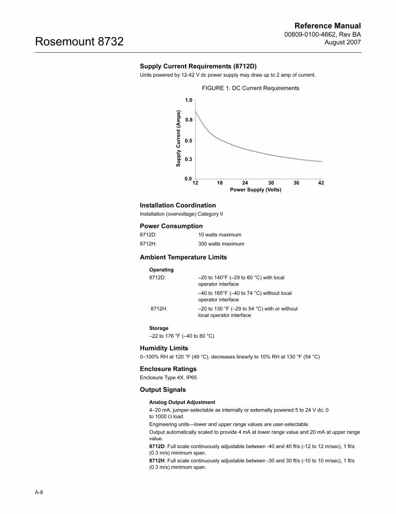
Reference Manual00809-0100-4662, Rev BA
August 2007Rosemount 8732
Supply Current Requirements (8712D)
Units powered by 12-42 V dc power supply may draw up to 2 amp of current.
FIGURE 1. DC Current Requirements
Installation Coordination
Installation (overvoltage) Category II
Power Consumption
Ambient Temperature Limits
Operating
Storage
–22 to 176 °F (–40 to 80 °C)
Humidity Limits
0–100% RH at 120 °F (49 °C), decreases linearly to 10% RH at 130 °F (54 °C)
Enclosure Ratings
Enclosure Type 4X, IP65
Output Signals
Analog Output Adjustment
4–20 mA, jumper-selectable as internally or externally powered 5 to 24 V dc; 0
to 1000 Ω load.
Engineering units—lower and upper range values are user-selectable.
Output automatically scaled to provide 4 mA at lower range value and 20 mA at upper range
value.
8712D: Full scale continuously adjustable between -40 and 40 ft/s (-12 to 12 m/sec), 1 ft/s
(0.3 m/s) minimum span.
8712H: Full scale continuously adjustable between -30 and 30 ft/s (-10 to 10 m/sec), 1 ft/s
(0.3 m/s) minimum span.
8712D: 10 watts maximum
8712H: 300 watts maximum
8712D: –20 to 140°F (–29 to 60 °C) with local
operator interface
–40 to 165°F (–40 to 74 °C) without local
operator interface
8712H: –20 to 130 °F (–29 to 54 °C) with or without
local operator interface
12 18 24 30 36 420.0
0.3
0.8
1.0
0.5
Power Supply (Volts)
Su
pp
ly C
urr
en
t (A
mp
s)
A-8
Reference Manual 00809-0100-4662, Rev BA
August 2007 Rosemount 8732
HART Communications, digital flow signal, superimposed on 4–20 mA signal, available for
control system interface. 250 Ω required for HART communications.
Scalable Frequency Adjustment
8712D: 0-10,000Hz, externally powered at 5 to 24 V dc, transistor switch closure supports
power loads up to 2W for frequencies up to 4000Hz, and 5 V dc at 0.1 W at maximum
frequency of 10,000 Hz. Pulse can be set to equal desired velocity or volume in user
selectable engineering units. Pulse width is adjustable from 1.5 to 500 msec, below 1.5 msec
pulse width automatically switches to 50% duty cycle.
8712H: 0-1000 Hz, externally powered at 5 to 24 V dc, transistor switch closure up to 5.75 W.
Pulse value can be set to equal desired volume in selected engineering units. Pulse width
adjustable from 0.5 to 100 m/s. Local operator interface automatically calculates and displays
maximum allowable output frequency.
Auxiliary Output Function
Externally powered at 5 to 24 V dc, transistor switch closure up to 3 W to indicate either:
Reverse Flow: Activates switch closure output when reverse flow is detected. The reverse
flow rate is displayed.
Zero Flow: Activates switch closure output when flow goes to 0 ft/s.
Positive Zero Return (PZR)
Forces outputs of the transmitter to the zero flow rate signal level. Activated by applying a
contact closure.
Software Lockout
Security lockout jumper on the electronics board can be set to deactivate all LOI and
HART-based communicator functions to protect configuration variables from unwanted or
accidental change.
Output Testing
Analog Output Test
Transmitter may be commanded to supply a specified current between 3.75 and 23.25 mA
Pulse Output Test
8712D: Transmitter may be commanded to supply a specified frequency between 1 pulse/
day and 10,000 Hz
8712H: Transmitter may be commanded to supply a specified frequency between 1 and 1000
Hz
Turn-on Time
8712D: 5 minutes to rated accuracy from power up, 5 seconds from power interruption
8712H: 30 minutes to rated accuracy from power up, 5 seconds from power interruption
Start-up Time
0.2 seconds from zero flow
Low Flow Cutoff
Adjustable between 0.04 and 1 ft/s (0.01 and 0.3 m/s). Below selected value, output is driven to
the zero flow rate signal level.
(8712D is adjustable between 0.01 and 1 ft/s).
Overrange Capability
Signal output will remain linear until 110% of upper range value. The signal output will remain
constant above these values. Out of range message displayed on LOI and the
HART Communicator.
Damping
8712D: Adjustable between 0.0 and 256 seconds
8712H: Adjustable between 0.2 and 256 seconds
A-9
Reference Manual00809-0100-4662, Rev BA
August 2007Rosemount 8732
Flowtube Sensor Compensation
Rosemount flowtube sensors are flow-calibrated and assigned a calibration factor at the factory.
The calibration factor is entered into the transmitter, enabling interchangeability of flowtube
sensors without calculations or a compromise in accuracy.
8712D transmitters and other manufacturer’s flowtube sensors can be calibrated at known
process conditions or at the Rosemount NIST-Traceable Flow Facility. Transmitters calibrated on
site require a two-step procedure to match a known flow rate.
Performance Specifications
(System specifications are given using the frequency output and with the unit at referenced
conditions.)
Accuracy(1)
Includes the combined effects of linearity, hysteresis, repeatability, and calibration uncertainty.
Rosemount 8712D with 8705/8707 Flowtube Sensor:
Standard system accuracy is ±0.25% of rate ±1.0 mm/sec from 0.04 to 6 ft/s (0.01 to 2 m/s);
above 6 ft/s (2 m/s), the system has an accuracy of ±0.25% of rate ±1.5 mm/sec.
Optional high accuracy is ±0.15% of rate ±1.0 mm/sec from 0.04 to 13 ft/s (0.01 to 4 m/s);
above 13 ft/s (4 m/s), the system has an accuracy of ±0.18% of rate.(2)
Rosemount 8712D with 8711 Flowtube Sensor:
Standard system accuracy is ±0.25% of rate ±2.0 mm/sec from 0.04 to 40 ft/s (0.01 to 12
m/s).
Optional high accuracy is ±0.15% of rate ±1.0 mm/sec from 0.04 to 13 ft/s (0.01 to 4 m/s);
above 13 ft/s (4 m/s), the system has an accuracy of ±0.18% of rate.
Rosemount 8712D with 8721 Flowtube Sensor:
Standard system accuracy is ±0.5% of rate from 1 to 40 ft/s (0.3 to 12 m/s); between 0.04 and
1.0 ft/s (0.01 and 0.3 m/s), the system has an accuracy of ±0.005 ft/s (0.0015 m/s).
Optional high accuracy is ±0.25% of rate from 3 to 40 ft/s (1 to 12 m/s).
Rosemount 8712D with Other Manufacturers’ Flowtube Sensors:
When calibrated in the Rosemount Flow Facility, system accuracies as good as 0.5% of rate
can be attained.
There is no accuracy specification for other manufacturers’ flowtube sensors calibrated in the
process line.
Rosemount 8712H with 8707 Flowtube Sensor
System accuracy is ±0.5% of rate from 3 to 30 ft/s (1 to 10 m/s); between 0.04 and 3.0 ft/s
(0.01 and 0.3 m/s), the system has an accuracy of ±0.015 ft/s (0.005 m/s).
Analog Output Effect
8712D: Analog output has the same accuracy as frequency output plus an additional 0.05% of
span.
8712H: Analog output has the same accuracy as frequency output plus an additional 0.1% of
span.
Vibration Effect
±0.1% of span per SAMA PMC 31.1, Level 2
Repeatability
±0.1% of reading
(1) Operating at Coil Drive Frequency of 37 Hz increases uncertainty by ±0.05% of rate.
(2) For Flowtube Sensor sizes greater than 12 in. (300 mm) the high accuracy is ±0.25% of rate
from 3 to 40 ft/sec (1 to 12 m/sec).
A-10

Reference Manual 00809-0100-4662, Rev BA
August 2007 Rosemount 8732
A-11
Response Time
0.2 seconds maximum response to step change in input
Stability
±0.1% of rate over six months
Reference Manual00809-0100-4662, Rev BA
August 2007Rosemount 8732
Ambient Temperature Effect
8712D: 0.25% over operating temperature range
8712H: ±1% per 100 °F (37.8 °C)
RFI EffectClass 1, A, B, C: ±0.5% of span at 3 V/m per SAMA PMC 33.1, wires and conduit
EN61326-1 1997 + A1/A2 (Industrial) electromagnetic compatibility (EMC) for process and
laboratory apparatus.
Supply Voltage EffectTransmitter meets supply voltage effect requirements of SAMA PMC 31.1, Section 5.10.1 through
5.10.5. Transmitter withstands surges in supply voltage as specified in IEEE 472, 1974
Physical Specifications Materials of Construction
Housing
Low-copper aluminum, NEMA 4X and IEC 60529 IP65
Pollution Degree 2
Paint
Polyurethane
Cover Gasket
Rubber
Electrical Connections
Four 1/2–14 NPT connections provided on the base of the transmitter. Screw terminals provided
for all of the connections. Power wiring connected to the transmitter only. Remote mounted
transmitters require only a single conduit connection to the flowtube sensor.
NOTEIf 3/4 - 14 NPT connections are required, 1/2 to 3/4 inch adapter kits are available for order.
Line Power Fuses
90–250 V ac systems (8712D)
2 amp, Quick-acting Bussman AGCI or equivalent
12–42 V dc systems (8712D)
3 amp, Quick-acting Bussman AGCI or equivalent
115 V ac systems (8712H)
5 amp, Quick-acting Bussman AGCI or equivalent (Rosemount 8712H only).
Transmitter WeightTransmitter approximately 9 lb (4 kg). Add 1 lb (0.5 kg) for local operator interface.
A-12
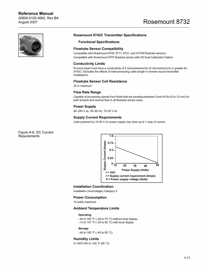
Reference Manual 00809-0100-4662, Rev BA
August 2007 Rosemount 8732
Rosemount 8742C Transmitter Specifications
Functional Specifications
Flowtube Sensor Compatibility
Compatible with Rosemount 8705, 8711, 8721, and 570TM flowtube sensors.
Compatible with Rosemount 8707 flowtube sensor with D2 Dual Calibration Option.
Conductivity Limits
Process liquid must have a conductivity of 5 microsiemens/cm (5 micromhos/cm) or greater for
8742C. Excludes the effects of interconnecting cable length in remote mount transmitter
installations.
Flowtube Sensor Coil Resistance
25 � maximum
Flow Rate Range
Capable of processing signals from fluids that are traveling between 0 and 40 ft/s (0 to 12 m/s) for
both forward and reverse flow in all flowtube sensor sizes.
Power Supply
90–250 V ac, 50–60 Hz, 15–50 V dc
Supply Current Requirements
Units powered by 15-50 V dc power supply may draw up to 1 amp of current.
Figure A-6. DC Current Requirements
Installation Coordination
Installation (overvoltage) Category II
Power Consumption
10 watts maximum
Ambient Temperature Limits
Operating
–40 to 165 °F (–40 to 74 °C) without local display
–13 to 147 °F (–25 to 65 °C) with local display
Storage
–40 to 185 °F (–40 to 85 °C)
Humidity Limits
0–100% RH to 150 °F (65 °C)
Power Supply (Volts)
15 5020 30 40
Su
pp
ly C
urr
en
t (A
mp
s)
1.0
0.75
0.5
0.25
0
I = 10/V
I = Supply current requirement (Amps)
V = Power supply voltage (Volts)
A-13
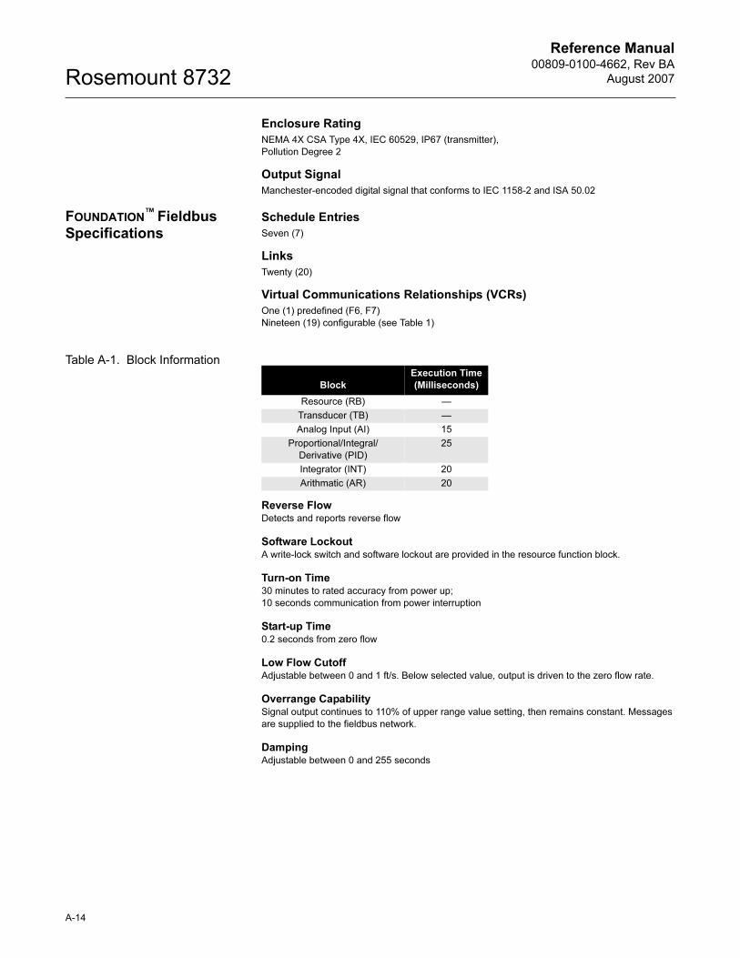
Reference Manual00809-0100-4662, Rev BA
August 2007Rosemount 8732
Enclosure Rating
NEMA 4X CSA Type 4X, IEC 60529, IP67 (transmitter),
Pollution Degree 2
Output Signal
Manchester-encoded digital signal that conforms to IEC 1158-2 and ISA 50.02
FOUNDATION™ Fieldbus
SpecificationsSchedule Entries
Seven (7)
Links
Twenty (20)
Virtual Communications Relationships (VCRs)
One (1) predefined (F6, F7)
Nineteen (19) configurable (see Table 1)
Table A-1. Block Information
Reverse FlowDetects and reports reverse flow
Software LockoutA write-lock switch and software lockout are provided in the resource function block.
Turn-on Time30 minutes to rated accuracy from power up;
10 seconds communication from power interruption
Start-up Time0.2 seconds from zero flow
Low Flow CutoffAdjustable between 0 and 1 ft/s. Below selected value, output is driven to the zero flow rate.
Overrange CapabilitySignal output continues to 110% of upper range value setting, then remains constant. Messages
are supplied to the fieldbus network.
DampingAdjustable between 0 and 255 seconds
Block
Execution Time
(Milliseconds)
Resource (RB) —
Transducer (TB) —
Analog Input (AI) 15
Proportional/Integral/
Derivative (PID)
25
Integrator (INT) 20
Arithmatic (AR) 20
A-14
Reference Manual 00809-0100-4662, Rev BA
August 2007 Rosemount 8732
Performance Specifications
(System specifications are given using the unit at referenced conditions.)
Accuracy(1)
Includes the combined effects of linearity, hysteresis, repeatability, and calibration uncertainty.
Rosemount 8742C with 8705/8707 Flowtube Sensor:
Standard system accuracy is ±0.3% of rate ±1.0 mm/sec from 0.04 to 40 ft/s (0.01 to 12 m/s).
Optional high accuracy is ±0.2% of rate ±1.0 mm/sec from 0.04 to 40 ft/s (0.01 to 12 m/s)(2).
Rosemount 8742C with 8711 Flowtube Sensor:
Standard system accuracy is ±0.3% of rate ±2.0 mm/sec from 0.04 to 40 ft/s (0.01 to 12 m/s).
Optional high accuracy is ±0.2% of rate ±1.0 mm/sec from 0.04 to 40 ft/s (0.01 to 12 m/s).
Rosemount 8742C with 8721 Flowtube Sensor:
Standard system accuracy is ±0.5% of rate from 1 to 40 ft/s (0.3 to 12 m/s); between 0.04 and
1.0 ft/s (0.01 and 0.3 m/s), the system has an accuracy of ±0.005 ft/s (0.0015 m/s).
Optional high accuracy is ±0.25% of rate from 3 to 40 ft/s (1 to 12 m/s).
Vibration EffectIEC 60770-1
Repeatability±0.1% of reading
Response Time0.2 seconds maximum response to step change in input
Stability±0.1% of rate over six months
Ambient Temperature Effect±0.25% of rate over operating temperature range
EMC ComplianceEN61326-1 1997 + A1/A2 3(Industrial) electromagnetic compatibility (EMC) for process and
laboratory apparatus.
Transient ProtectionThe 8742C transmitter prevents damage to the flowmeter from transients compliant to:
IEC 6100 – 4-4 (for burst currents)
IEC 6100 – 4-5 (for surge currents)
Mounting Position EffectNone when installed to ensure flowtube sensor remains full
Physical Specifications Materials of Construction (Transmitter)
Housing
Low-copper aluminum
Paint
Polyurethane
Cover Gasket
Rubber
(1) Operating at Coil Drive Frequency of 37 Hz increases uncertainty by ±0.05% of rate.
(2) For Flowtube Sensor sizes greater than 12 in. (300 mm) the high accuracy is ±0.25% of rate
from 3 to 40 ft/sec (1 to 12 m/sec).
A-15
Reference Manual00809-0100-4662, Rev BA
August 2007Rosemount 8732
Electrical Connections
Two 1/2–14 NPT with number 8 screw terminal connections are provided for electrical wiring.
PG13.5 and CM20 adapters are available. Screw terminals provided for all connections. Power
wiring connected to transmitter only. Integrally mounted transmitters are factory wired to the
flowtube sensor.
Mounting
Integrally mounted transmitters do not require interconnecting cables. The local display and
transmitter can be rotated in 90° increments. Remote mounted transmitters require only a single
conduit connection to the flowtube sensor.
Weight
Approximately 7 pounds (3.2 kg). Add 0.5 pounds (0.5 kg) for local display.
A-16
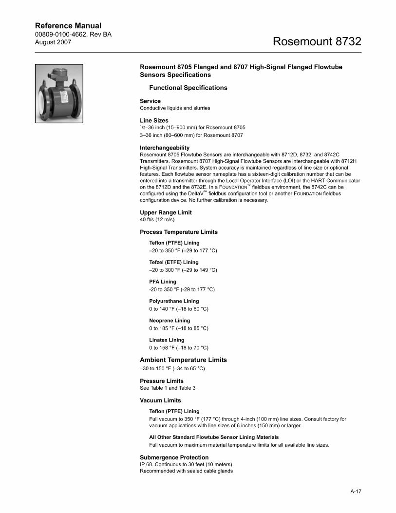
Reference Manual 00809-0100-4662, Rev BA
August 2007 Rosemount 8732
Rosemount 8705 Flanged and 8707 High-Signal Flanged Flowtube Sensors Specifications
Functional Specifications
ServiceConductive liquids and slurries
Line Sizes1/2–36 inch (15–900 mm) for Rosemount 8705
3–36 inch (80–600 mm) for Rosemount 8707
InterchangeabilityRosemount 8705 Flowtube Sensors are interchangeable with 8712D, 8732, and 8742C
Transmitters. Rosemount 8707 High-Signal Flowtube Sensors are interchangeable with 8712H
High-Signal Transmitters. System accuracy is maintained regardless of line size or optional
features. Each flowtube sensor nameplate has a sixteen-digit calibration number that can be
entered into a transmitter through the Local Operator Interface (LOI) or the HART Communicator
on the 8712D and the 8732E. In a FOUNDATION™ fieldbus environment, the 8742C can be
configured using the DeltaV™ fieldbus configuration tool or another FOUNDATION fieldbus
configuration device. No further calibration is necessary.
Upper Range Limit40 ft/s (12 m/s)
Process Temperature Limits
Teflon (PTFE) Lining
–20 to 350 °F (–29 to 177 °C)
Tefzel (ETFE) Lining
–20 to 300 °F (–29 to 149 °C)
PFA Lining
-20 to 350 °F (-29 to 177 °C)
Polyurethane Lining
0 to 140 °F (–18 to 60 °C)
Neoprene Lining
0 to 185 °F (–18 to 85 °C)
Linatex Lining
0 to 158 °F (–18 to 70 °C)
Ambient Temperature Limits
–30 to 150 °F (–34 to 65 °C)
Pressure LimitsSee Table 1 and Table 3
Vacuum Limits
Teflon (PTFE) Lining
Full vacuum to 350 °F (177 °C) through 4-inch (100 mm) line sizes. Consult factory for
vacuum applications with line sizes of 6 inches (150 mm) or larger.
All Other Standard Flowtube Sensor Lining Materials
Full vacuum to maximum material temperature limits for all available line sizes.
Submergence ProtectionIP 68. Continuous to 30 feet (10 meters)
Recommended with sealed cable glands
A-17

Reference Manual00809-0100-4662, Rev BA
August 2007Rosemount 8732
Conductivity LimitsProcess liquid must have a conductivity of 5 microsiemens/cm (5 micromhos/cm) or greater for
8705. Process liquid must have a conductivity of 50 microsiemens/cm (50 micromhos/cm) for
8707 when used with 8712H, 5 microsiemens/cm when used with other transmitters. Excludes
the effect of interconnecting cable length in remote mount transmitter installations.
A-18
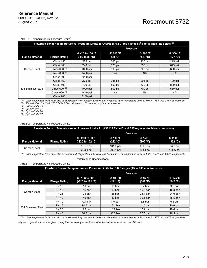
Reference Manual 00809-0100-4662, Rev BA
August 2007 Rosemount 8732
Performance Specifications
(System specifications are given using the frequency output and with the unit at referenced conditions.)
TABLE 1. Temperature vs. Pressure Limits(1)
Flowtube Sensor Temperature vs. Pressure Limits for ASME B16.5 Class Flanges (1/2- to 36-inch line sizes) (2)
Pressure
Flange Material Flange Rating@ -20 to 100 °F(-29 to 38 °C)
@ 200 °F(93 °C)
@ 300 °F(149 °C)
@ 350 °F(177 °C)
Carbon Steel
Class 150 285 psi 260 psi 230 psi 215 psi
Class 300 740 psi 675 psi 655 psi 645 psi
Class 600 (3) 1000 psi 800 psi 700 psi 650 psi
Class 600 (4) 1480 psi NA NA NA
Class 900 2220 psi
304 Stainless Steel
Class 150 275 psi 235 psi 205 psi 190 psi
Class 300 720 psi 600 psi 530 psi 500 psi
Class 600 (5) 1000 psi 800 psi 700 psi 650 psi
Class 600 (6) 1440 psi NA NA NA
Class 900 2160 psi
(1) Liner temperature limits must also be considered. Polyurethane, Linatex, and Neoprene have temperature limits of 140°F, 158°F, and 185°F, respectively.(2) 30- and 36-inch AWWA C207 Table 2 Class D rated to 150 psi at atmospheric temperature.(3) Option Code C6(4) Option Code C7(5) Option Code S6(6) Option Code S7
TABLE 2. Temperature vs. Pressure Limits (1)
Flowtube Sensor Temperature vs. Pressure Limits for AS2129 Table D and E Flanges (4- to 24-inch line sizes)
Pressure
Flange Material Flange Rating@ -200 to 50 °F(-320 to 122 °C)
@ 100 °F(212 °C)
@ 150°F(302 °C)
@ 200 °F(392 °C)
Carbon SteelD 101.6 psi 101.6 psi 101.6 psi 94.3 psi
E 203.1 psi 203.1 psi 203.1 psi 188.6 psi
(1) Liner temperature limits must also be considered. Polyurethane, Linatex, and Neoprene have temperature limits of 140°F, 158°F, and 185°F, respectively.
TABLE 3. Temperature vs. Pressure Limits (1)
Flowtube Sensor Temperature vs. Pressure Limits for DIN Flanges (15 to 600 mm line sizes)
Pressure
Flange Material Flange Rating@ -196 to 50 °C(-320 to 122 °F)
@ 100 °C(212 °F)
@ 150°C(302 °F)
@ 175°C(347 °F)
Carbon Steel
PN 10 10 bar 10 bar 9.7 bar 9.5 bar
PN 16 16 bar 16 bar 15.6 bar 15.3 bar
PN 25 25 bar 25 bar 24.4 bar 24.0 bar
PN 40 40 bar 40 bar 39.1 bar 38.5 bar
304 Stainless Steel
PN 10 9.1 bar 7.5 bar 6.8 bar 6.5 bar
PN 16 14.7 bar 12.1 bar 11.0 bar 10.6 bar
PN 25 23 bar 18.9 bar 17.2 bar 16.6 bar
PN 40 36.8 bar 30.3 bar 27.5 bar 26.5 bar
(1) Liner temperature limits must also be considered. Polyurethane, Linatex, and Neoprene have temperature limits of 140°F, 158°F, and 185°F, respectively.
A-19
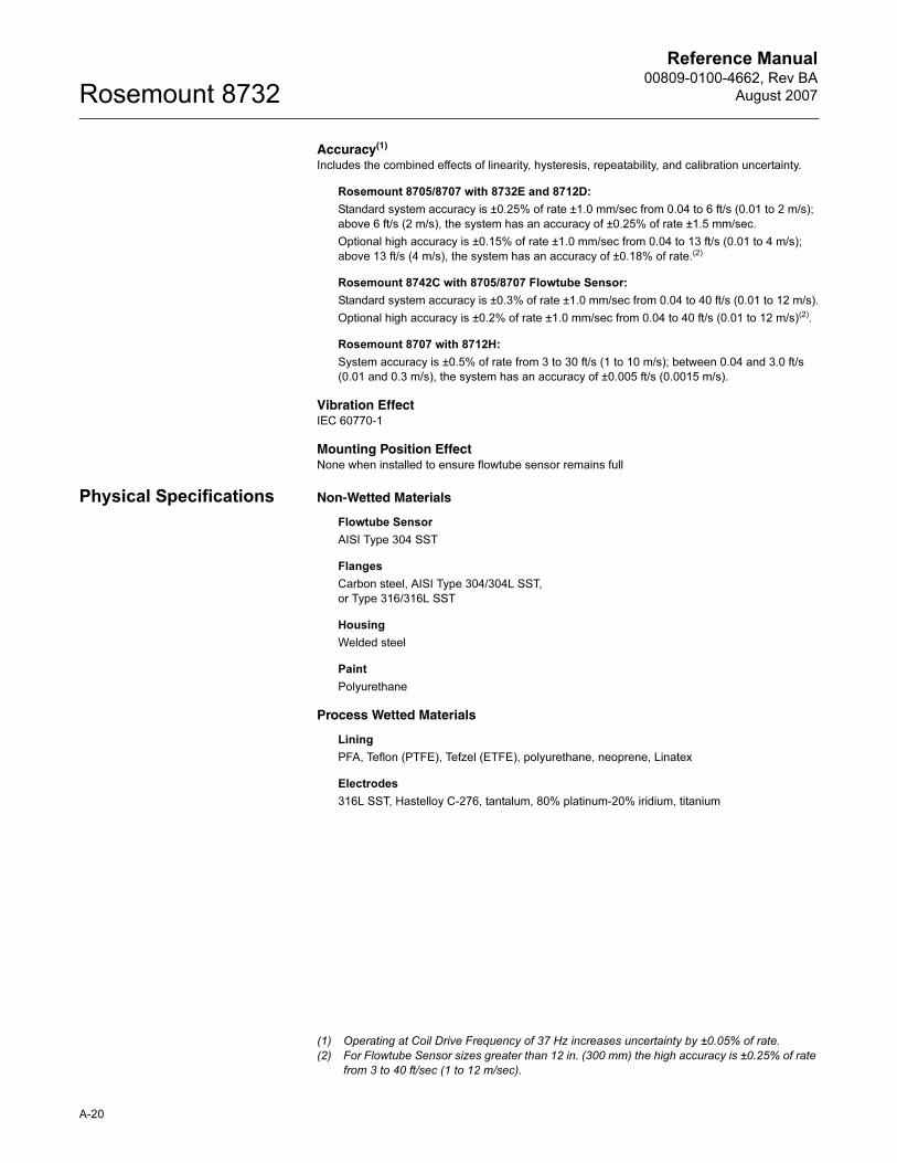
Reference Manual00809-0100-4662, Rev BA
August 2007Rosemount 8732
Accuracy(1)
Includes the combined effects of linearity, hysteresis, repeatability, and calibration uncertainty.
Rosemount 8705/8707 with 8732E and 8712D:
Standard system accuracy is ±0.25% of rate ±1.0 mm/sec from 0.04 to 6 ft/s (0.01 to 2 m/s);
above 6 ft/s (2 m/s), the system has an accuracy of ±0.25% of rate ±1.5 mm/sec.
Optional high accuracy is ±0.15% of rate ±1.0 mm/sec from 0.04 to 13 ft/s (0.01 to 4 m/s);
above 13 ft/s (4 m/s), the system has an accuracy of ±0.18% of rate.(2)
Rosemount 8742C with 8705/8707 Flowtube Sensor:
Standard system accuracy is ±0.3% of rate ±1.0 mm/sec from 0.04 to 40 ft/s (0.01 to 12 m/s).
Optional high accuracy is ±0.2% of rate ±1.0 mm/sec from 0.04 to 40 ft/s (0.01 to 12 m/s)(2).
Rosemount 8707 with 8712H:
System accuracy is ±0.5% of rate from 3 to 30 ft/s (1 to 10 m/s); between 0.04 and 3.0 ft/s
(0.01 and 0.3 m/s), the system has an accuracy of ±0.005 ft/s (0.0015 m/s).
Vibration EffectIEC 60770-1
Mounting Position EffectNone when installed to ensure flowtube sensor remains full
Physical Specifications Non-Wetted Materials
Flowtube Sensor
AISI Type 304 SST
Flanges
Carbon steel, AISI Type 304/304L SST,
or Type 316/316L SST
Housing
Welded steel
Paint
Polyurethane
Process Wetted Materials
Lining
PFA, Teflon (PTFE), Tefzel (ETFE), polyurethane, neoprene, Linatex
Electrodes
316L SST, Hastelloy C-276, tantalum, 80% platinum-20% iridium, titanium
(1) Operating at Coil Drive Frequency of 37 Hz increases uncertainty by ±0.05% of rate.
(2) For Flowtube Sensor sizes greater than 12 in. (300 mm) the high accuracy is ±0.25% of rate
from 3 to 40 ft/sec (1 to 12 m/sec).
A-20
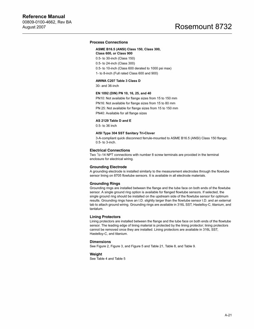
Reference Manual 00809-0100-4662, Rev BA
August 2007 Rosemount 8732
Process Connections
ASME B16.5 (ANSI) Class 150, Class 300,
Class 600, or Class 900
0.5- to 30-inch (Class 150)
0.5- to 24-inch (Class 300)
0.5- to 10-inch (Class 600 derated to 1000 psi max)
1- to 8-inch (Full rated Class 600 and 900)
AWWA C207 Table 3 Class D
30- and 36-inch
EN 1092 (DIN) PN 10, 16, 25, and 40
PN10: Not available for flange sizes from 15 to 150 mm
PN16: Not available for flange sizes from 15 to 80 mm
PN 25: Not available for flange sizes from 15 to 150 mm
PN40: Available for all flange sizes
AS 2129 Table D and E
0.5- to 36 inch
AISI Type 304 SST Sanitary Tri-Clover
3-A-compliant quick disconnect ferrule-mounted to ASME B16.5 (ANSI) Class 150 flange;
0.5- to 3-inch.
Electrical ConnectionsTwo 1/2–14 NPT connections with number 8 screw terminals are provided in the terminal
enclosure for electrical wiring.
Grounding ElectrodeA grounding electrode is installed similarly to the measurement electrodes through the flowtube
sensor lining on 8705 flowtube sensors. It is available in all electrode materials.
Grounding RingsGrounding rings are installed between the flange and the tube face on both ends of the flowtube
sensor. A single ground ring option is available for flanged flowtube sensors. If selected, the
single ground ring should be installed on the upstream side of the flowtube sensor for optimum
results. Grounding rings have an I.D. slightly larger than the flowtube sensor I.D. and an external
tab to attach ground wiring. Grounding rings are available in 316L SST, Hastelloy-C, titanium, and
tantalum.
Lining ProtectorsLining protectors are installed between the flange and the tube face on both ends of the flowtube
sensor. The leading edge of lining material is protected by the lining protector; lining protectors
cannot be removed once they are installed. Lining protectors are available in 316L SST,
Hastelloy-C, and titanium.
DimensionsSee Figure 2, Figure 3, and Figure 5 and Table 21, Table 8, and Table 9.
WeightSee Table 4 and Table 5
A-21
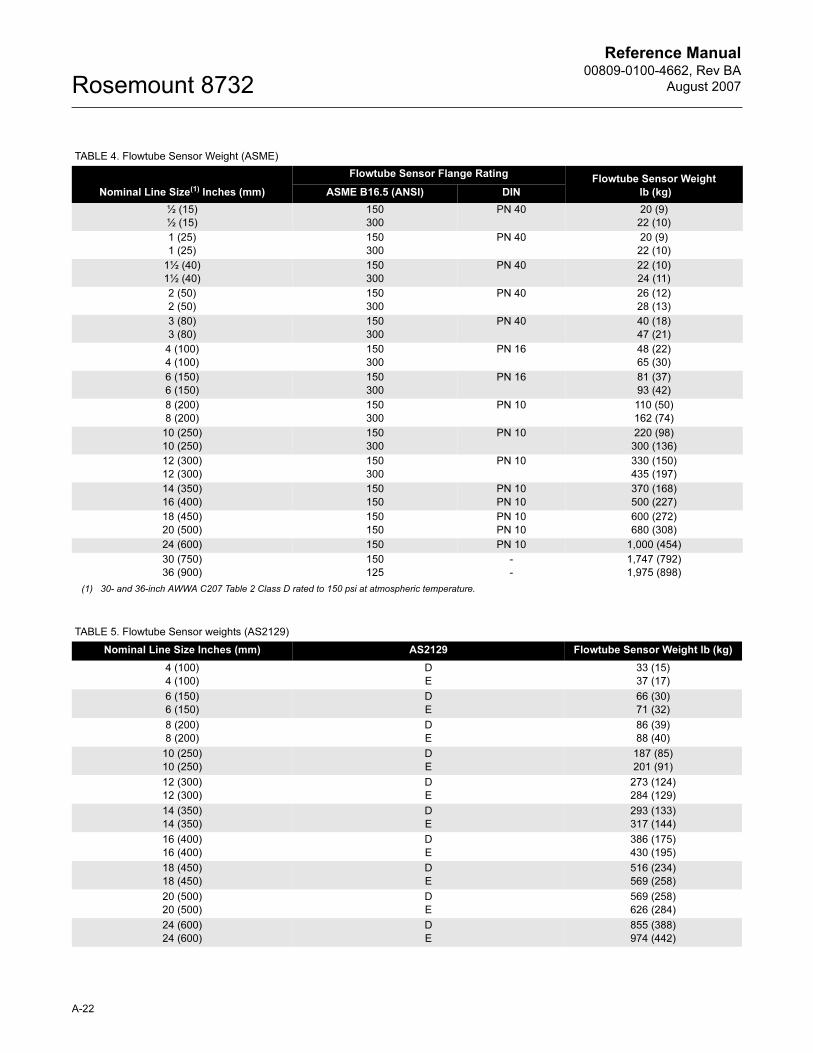
Reference Manual00809-0100-4662, Rev BA
August 2007Rosemount 8732
TABLE 4. Flowtube Sensor Weight (ASME)
Nominal Line Size(1) Inches (mm)
Flowtube Sensor Flange RatingFlowtube Sensor Weight
lb (kg)ASME B16.5 (ANSI) DIN
½ (15)
½ (15)
150
300
PN 40 20 (9)
22 (10)
1 (25)
1 (25)
150
300
PN 40 20 (9)
22 (10)
1½ (40)
1½ (40)
150
300
PN 40 22 (10)
24 (11)
2 (50)
2 (50)
150
300
PN 40 26 (12)
28 (13)
3 (80)
3 (80)
150
300
PN 40 40 (18)
47 (21)
4 (100)
4 (100)
150
300
PN 16 48 (22)
65 (30)
6 (150)
6 (150)
150
300
PN 16 81 (37)
93 (42)
8 (200)
8 (200)
150
300
PN 10 110 (50)
162 (74)
10 (250)
10 (250)
150
300
PN 10 220 (98)
300 (136)
12 (300)
12 (300)
150
300
PN 10 330 (150)
435 (197)
14 (350)
16 (400)
150
150
PN 10
PN 10
370 (168)
500 (227)
18 (450)
20 (500)
150
150
PN 10
PN 10
600 (272)
680 (308)
24 (600) 150 PN 10 1,000 (454)
30 (750)
36 (900)
150
125
-
-
1,747 (792)
1,975 (898)
(1) 30- and 36-inch AWWA C207 Table 2 Class D rated to 150 psi at atmospheric temperature.
TABLE 5. Flowtube Sensor weights (AS2129)
Nominal Line Size Inches (mm) AS2129 Flowtube Sensor Weight lb (kg)
4 (100)
4 (100)
D
E
33 (15)
37 (17)
6 (150)
6 (150)
D
E
66 (30)
71 (32)
8 (200)
8 (200)
D
E
86 (39)
88 (40)
10 (250)
10 (250)
D
E
187 (85)
201 (91)
12 (300)
12 (300)
D
E
273 (124)
284 (129)
14 (350)
14 (350)
D
E
293 (133)
317 (144)
16 (400)
16 (400)
D
E
386 (175)
430 (195)
18 (450)
18 (450)
D
E
516 (234)
569 (258)
20 (500)
20 (500)
D
E
569 (258)
626 (284)
24 (600)
24 (600)
D
E
855 (388)
974 (442)
A-22
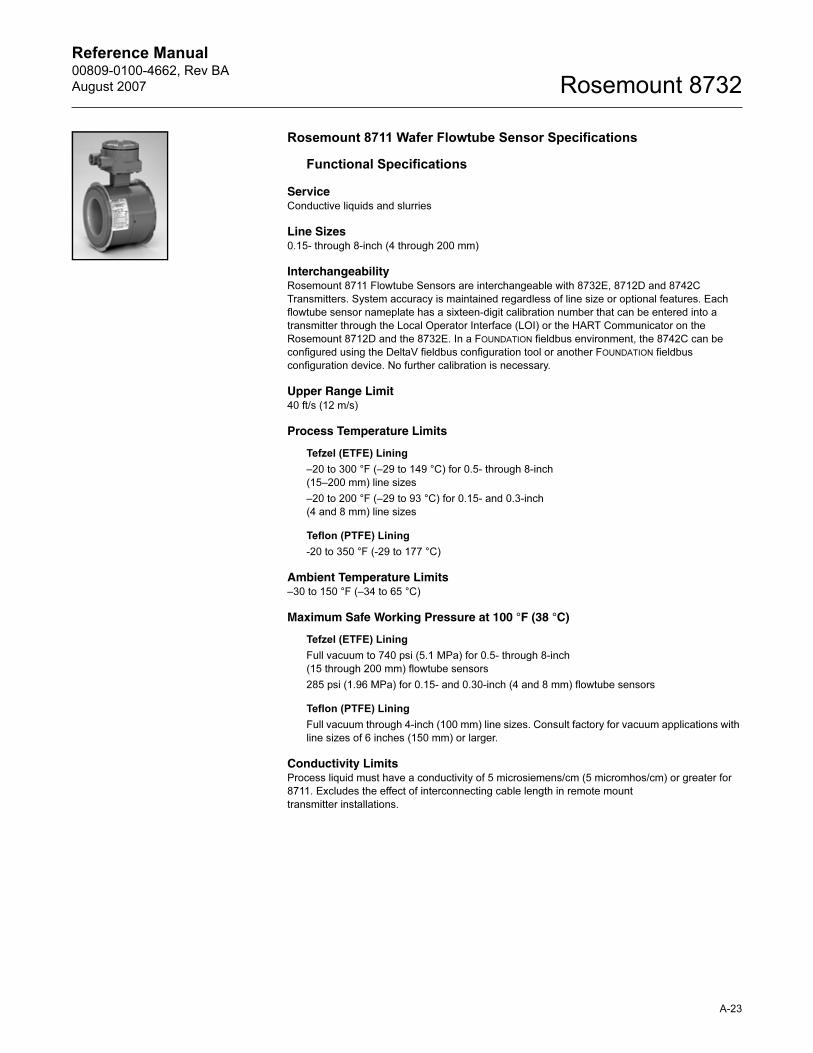
Reference Manual 00809-0100-4662, Rev BA
August 2007 Rosemount 8732
A-23
Rosemount 8711 Wafer Flowtube Sensor Specifications
Functional Specifications
ServiceConductive liquids and slurries
Line Sizes0.15- through 8-inch (4 through 200 mm)
InterchangeabilityRosemount 8711 Flowtube Sensors are interchangeable with 8732E, 8712D and 8742C
Transmitters. System accuracy is maintained regardless of line size or optional features. Each
flowtube sensor nameplate has a sixteen-digit calibration number that can be entered into a
transmitter through the Local Operator Interface (LOI) or the HART Communicator on the
Rosemount 8712D and the 8732E. In a FOUNDATION fieldbus environment, the 8742C can be
configured using the DeltaV fieldbus configuration tool or another FOUNDATION fieldbus
configuration device. No further calibration is necessary.
Upper Range Limit40 ft/s (12 m/s)
Process Temperature Limits
Tefzel (ETFE) Lining
–20 to 300 °F (–29 to 149 °C) for 0.5- through 8-inch
(15–200 mm) line sizes
–20 to 200 °F (–29 to 93 °C) for 0.15- and 0.3-inch
(4 and 8 mm) line sizes
Teflon (PTFE) Lining
-20 to 350 °F (-29 to 177 °C)
Ambient Temperature Limits–30 to 150 °F (–34 to 65 °C)
Maximum Safe Working Pressure at 100 °F (38 °C)
Tefzel (ETFE) Lining
Full vacuum to 740 psi (5.1 MPa) for 0.5- through 8-inch
(15 through 200 mm) flowtube sensors
285 psi (1.96 MPa) for 0.15- and 0.30-inch (4 and 8 mm) flowtube sensors
Teflon (PTFE) Lining
Full vacuum through 4-inch (100 mm) line sizes. Consult factory for vacuum applications with
line sizes of 6 inches (150 mm) or larger.
Conductivity LimitsProcess liquid must have a conductivity of 5 microsiemens/cm (5 micromhos/cm) or greater for
8711. Excludes the effect of interconnecting cable length in remote mount
transmitter installations.
Reference Manual00809-0100-4662, Rev BA
August 2007Rosemount 8732
Performance Specifications
(System specifications are given using the frequency output and with the unit at referenced
conditions.)
Accuracy(1)
Rosemount 8711 with 8732E and 8712D:
Standard system accuracy is ±0.25% of rate ±2.0 mm/sec from 0.04 to 40 ft/s (0.01 to 12
m/s).
Optional high accuracy is ±0.15% of rate ±1.0 mm/sec from 0.04 to 13 ft/s (0.01 to 4 m/s);
above 13 ft/s (4 m/s), the system has an accuracy of ±0.18% of rate.
Rosemount 8742C with 8711 Flowtube Sensor:
Standard system accuracy is ±0.3% of rate ±2.0 mm/sec from 0.04 to 40 ft/s (0.01 to 12 m/s).
Optional high accuracy is ±0.2% of rate ±1.0 mm/sec from 0.04 to 40 ft/s (0.01 to 12 m/s).
Vibration EffectIEC 60770-1
Mounting Position EffectNo effect when installed to ensure flowtube sensor remains full
Physical Specifications
Non-Wetted Materials
Flowtube Sensor
303 SST (ASTM A-743)
Coil Housing
Investment cast steel (ASTM A-27)
Paint
Polyurethane
Process-Wetted Materials
Lining
Tefzel (ETFE), Teflon (PTFE)
Electrodes
316L SST, Hastelloy C-276, tantalum,
80% platinum—20% iridium, titanium
(1) Operating at Coil Drive Frequency of 37 Hz increases uncertainty by ±0.05% of rate.
A-24
Reference Manual 00809-0100-4662, Rev BA
August 2007 Rosemount 8732
Process Connections
Mounts between these Flange Configurations
ASME B16.5 (ANSI): Class 150, 300
EN 1092 (DIN): PN 10 and 25
BS: 10 Table D, E, and F
Studs, Nuts, and Washers(1)
ASME B16.5 (ANSI)
0.15- through 1-inch (4 through 25 mm):
316 SST, ASTM A193, Grade B8M, Class 1 threaded mounting studs; ASTM A194, Grade
8M heavy hex nuts; SAE per ANSI B18.2.1, Type A, Series N flat washers.
1.5- through 8-inch (40 through 200 mm):
CS, ASTM A193, Grade B7, Class 1 threaded mounting studs; ASTM A194, Grade 2H heavy
hex nuts; SAE per ANSI B18.2.1, Type A, Series N flat washers; all items clear, chromate
zinc-plated.
EN 1092 (DIN)
4 through 25 mm (0.15- through 1-inch):
316 SST ASTM A193, Grade B8M Class 1 threaded mounting studs; ASTM A194, Grade 8M,
DIN 934 H=D, metric heavy hex nuts; 316 SST, A4, DIN 125 flat washers.
40 through 200 mm (1.5- through 8-inch):
CS, ASTM A193, Grade B7 threaded mounting studs; ASTM A194, Grade 2H, DIN 934 H=D,
metric heavy hex nuts; CS, DIN 125 flat washers; all items yellow zinc-plated.
Electrical ConnectionsTwo 1/2–14 NPT connections with number 8 screw terminals are provided in the terminal
enclosure for electrical wiring.
Grounding ElectrodeA grounding electrode is installed similarly to the measurement electrodes through the flowtube
sensor lining. It is available in all electrode materials.
Grounding RingsGrounding rings are installed between the flange and the tube face on both ends of the flowtube
sensor. They have an I.D. slightly larger than the flowtube sensor I.D. and an external tab to
attach ground wiring. Grounding rings are available in 316L SST, Hastelloy C-276, titanium, and
tantalum.
Dimensions and WeightSee Figure 4, Figure 5, and Table 10
(1) 0.15 and 0.30 inch (4 and 80 mm) flowtube sensors mount between 1/2-inch flange.
A-25
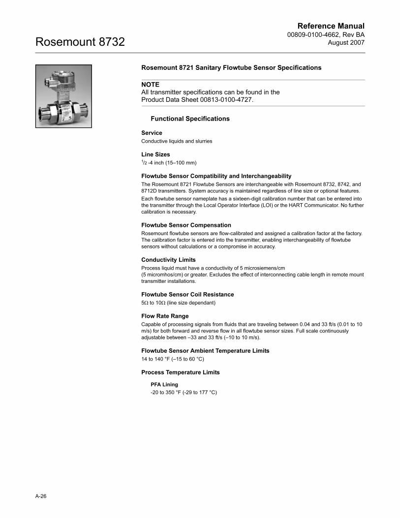
Reference Manual00809-0100-4662, Rev BA
August 2007Rosemount 8732
Rosemount 8721 Sanitary Flowtube Sensor Specifications
NOTEAll transmitter specifications can be found in the Product Data Sheet 00813-0100-4727.
Functional Specifications
Service
Conductive liquids and slurries
Line Sizes1/2 -4 inch (15–100 mm)
Flowtube Sensor Compatibility and Interchangeability
The Rosemount 8721 Flowtube Sensors are interchangeable with Rosemount 8732, 8742, and
8712D transmitters. System accuracy is maintained regardless of line size or optional features.
Each flowtube sensor nameplate has a sixteen-digit calibration number that can be entered into
the transmitter through the Local Operator Interface (LOI) or the HART Communicator. No further
calibration is necessary.
Flowtube Sensor Compensation
Rosemount flowtube sensors are flow-calibrated and assigned a calibration factor at the factory.
The calibration factor is entered into the transmitter, enabling interchangeability of flowtube
sensors without calculations or a compromise in accuracy.
Conductivity Limits
Process liquid must have a conductivity of 5 microsiemens/cm
(5 micromhos/cm) or greater. Excludes the effect of interconnecting cable length in remote mount
transmitter installations.
Flowtube Sensor Coil Resistance
5Ω to 10Ω (line size dependant)
Flow Rate Range
Capable of processing signals from fluids that are traveling between 0.04 and 33 ft/s (0.01 to 10
m/s) for both forward and reverse flow in all flowtube sensor sizes. Full scale continuously
adjustable between –33 and 33 ft/s (–10 to 10 m/s).
Flowtube Sensor Ambient Temperature Limits
14 to 140 °F (–15 to 60 °C)
Process Temperature Limits
PFA Lining
-20 to 350 °F (-29 to 177 °C)
A-26
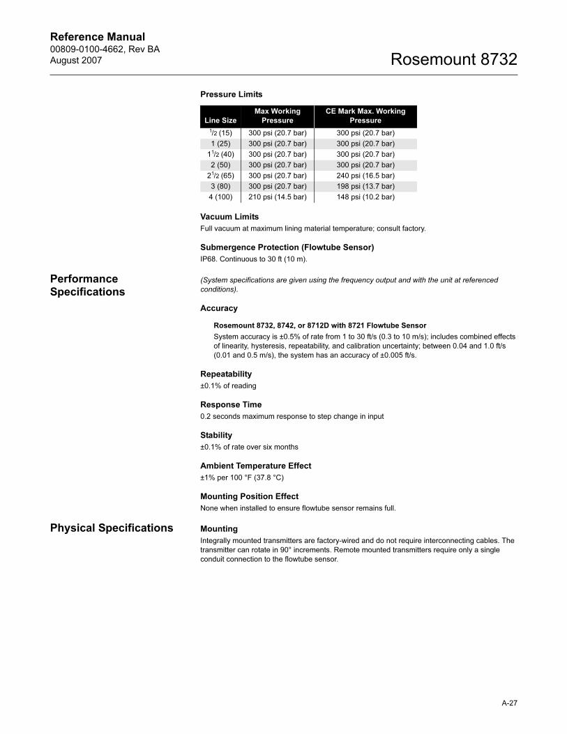
Reference Manual 00809-0100-4662, Rev BA
August 2007 Rosemount 8732
Pressure Limits
Vacuum Limits
Full vacuum at maximum lining material temperature; consult factory.
Submergence Protection (Flowtube Sensor)
IP68. Continuous to 30 ft (10 m).
Performance Specifications
(System specifications are given using the frequency output and with the unit at referenced
conditions).
Accuracy
Rosemount 8732, 8742, or 8712D with 8721 Flowtube Sensor
System accuracy is ±0.5% of rate from 1 to 30 ft/s (0.3 to 10 m/s); includes combined effects
of linearity, hysteresis, repeatability, and calibration uncertainty; between 0.04 and 1.0 ft/s
(0.01 and 0.5 m/s), the system has an accuracy of ±0.005 ft/s.
Repeatability
±0.1% of reading
Response Time
0.2 seconds maximum response to step change in input
Stability
±0.1% of rate over six months
Ambient Temperature Effect
±1% per 100 °F (37.8 °C)
Mounting Position Effect
None when installed to ensure flowtube sensor remains full.
Physical Specifications Mounting
Integrally mounted transmitters are factory-wired and do not require interconnecting cables. The
transmitter can rotate in 90° increments. Remote mounted transmitters require only a single
conduit connection to the flowtube sensor.
Line Size
Max Working
Pressure
CE Mark Max. Working
Pressure
1/2 (15) 300 psi (20.7 bar) 300 psi (20.7 bar)
1 (25) 300 psi (20.7 bar) 300 psi (20.7 bar)
11/2 (40) 300 psi (20.7 bar) 300 psi (20.7 bar)
2 (50) 300 psi (20.7 bar) 300 psi (20.7 bar)
21/2 (65) 300 psi (20.7 bar) 240 psi (16.5 bar)
3 (80) 300 psi (20.7 bar) 198 psi (13.7 bar)
4 (100) 210 psi (14.5 bar) 148 psi (10.2 bar)
A-27
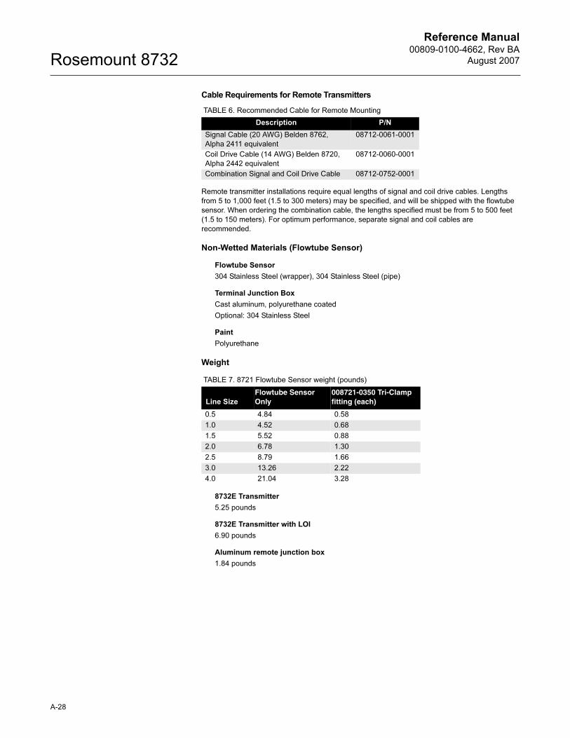
Reference Manual00809-0100-4662, Rev BA
August 2007Rosemount 8732
Cable Requirements for Remote Transmitters
Remote transmitter installations require equal lengths of signal and coil drive cables. Lengths
from 5 to 1,000 feet (1.5 to 300 meters) may be specified, and will be shipped with the flowtube
sensor. When ordering the combination cable, the lengths specified must be from 5 to 500 feet
(1.5 to 150 meters). For optimum performance, separate signal and coil cables are
recommended.
Non-Wetted Materials (Flowtube Sensor)
Flowtube Sensor
304 Stainless Steel (wrapper), 304 Stainless Steel (pipe)
Terminal Junction Box
Cast aluminum, polyurethane coated
Optional: 304 Stainless Steel
Paint
Polyurethane
Weight
8732E Transmitter
5.25 pounds
8732E Transmitter with LOI
6.90 pounds
Aluminum remote junction box
1.84 pounds
TABLE 6. Recommended Cable for Remote Mounting
Description P/N
Signal Cable (20 AWG) Belden 8762,
Alpha 2411 equivalent
08712-0061-0001
Coil Drive Cable (14 AWG) Belden 8720,
Alpha 2442 equivalent
08712-0060-0001
Combination Signal and Coil Drive Cable 08712-0752-0001
TABLE 7. 8721 Flowtube Sensor weight (pounds)
Line Size
Flowtube Sensor Only
008721-0350 Tri-Clamp fitting (each)
0.5 4.84 0.58
1.0 4.52 0.68
1.5 5.52 0.88
2.0 6.78 1.30
2.5 8.79 1.66
3.0 13.26 2.22
4.0 21.04 3.28
A-28
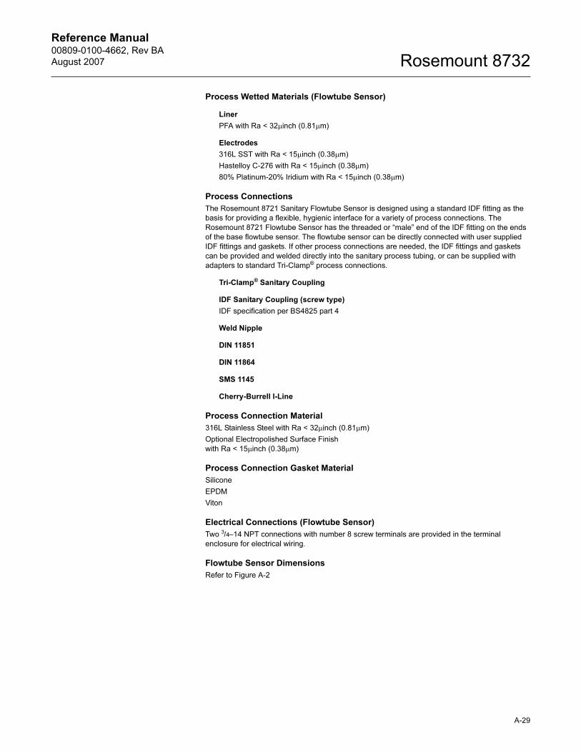
Reference Manual 00809-0100-4662, Rev BA
August 2007 Rosemount 8732
Process Wetted Materials (Flowtube Sensor)
Liner
PFA with Ra < 32μinch (0.81μm)
Electrodes
316L SST with Ra < 15μinch (0.38μm)
Hastelloy C-276 with Ra < 15μinch (0.38μm)
80% Platinum-20% Iridium with Ra < 15μinch (0.38μm)
Process Connections
The Rosemount 8721 Sanitary Flowtube Sensor is designed using a standard IDF fitting as the
basis for providing a flexible, hygienic interface for a variety of process connections. The
Rosemount 8721 Flowtube Sensor has the threaded or “male” end of the IDF fitting on the ends
of the base flowtube sensor. The flowtube sensor can be directly connected with user supplied
IDF fittings and gaskets. If other process connections are needed, the IDF fittings and gaskets
can be provided and welded directly into the sanitary process tubing, or can be supplied with
adapters to standard Tri-Clamp® process connections.
Tri-Clamp® Sanitary Coupling
IDF Sanitary Coupling (screw type)
IDF specification per BS4825 part 4
Weld Nipple
DIN 11851
DIN 11864
SMS 1145
Cherry-Burrell I-Line
Process Connection Material
316L Stainless Steel with Ra < 32μinch (0.81μm)
Optional Electropolished Surface Finish
with Ra < 15μinch (0.38μm)
Process Connection Gasket Material
Silicone
EPDM
Viton
Electrical Connections (Flowtube Sensor)
Two 3/4–14 NPT connections with number 8 screw terminals are provided in the terminal
enclosure for electrical wiring.
Flowtube Sensor Dimensions
Refer to Figure A-2
A-29
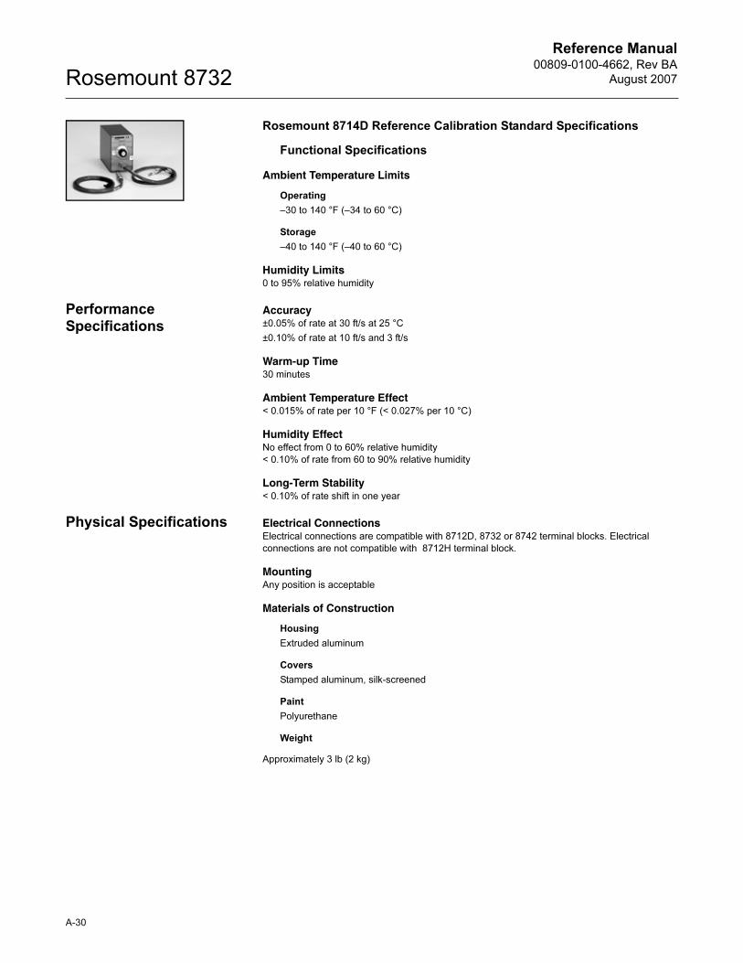
Reference Manual00809-0100-4662, Rev BA
August 2007Rosemount 8732
Rosemount 8714D Reference Calibration Standard Specifications
Functional Specifications
Ambient Temperature Limits
Operating
–30 to 140 °F (–34 to 60 °C)
Storage
–40 to 140 °F (–40 to 60 °C)
Humidity Limits0 to 95% relative humidity
Performance Specifications
Accuracy±0.05% of rate at 30 ft/s at 25 °C
±0.10% of rate at 10 ft/s and 3 ft/s
Warm-up Time30 minutes
Ambient Temperature Effect< 0.015% of rate per 10 °F (< 0.027% per 10 °C)
Humidity EffectNo effect from 0 to 60% relative humidity
< 0.10% of rate from 60 to 90% relative humidity
Long-Term Stability< 0.10% of rate shift in one year
Physical Specifications Electrical ConnectionsElectrical connections are compatible with 8712D, 8732 or 8742 terminal blocks. Electrical
connections are not compatible with 8712H terminal block.
MountingAny position is acceptable
Materials of Construction
Housing
Extruded aluminum
Covers
Stamped aluminum, silk-screened
Paint
Polyurethane
Weight
Approximately 3 lb (2 kg)
A-30
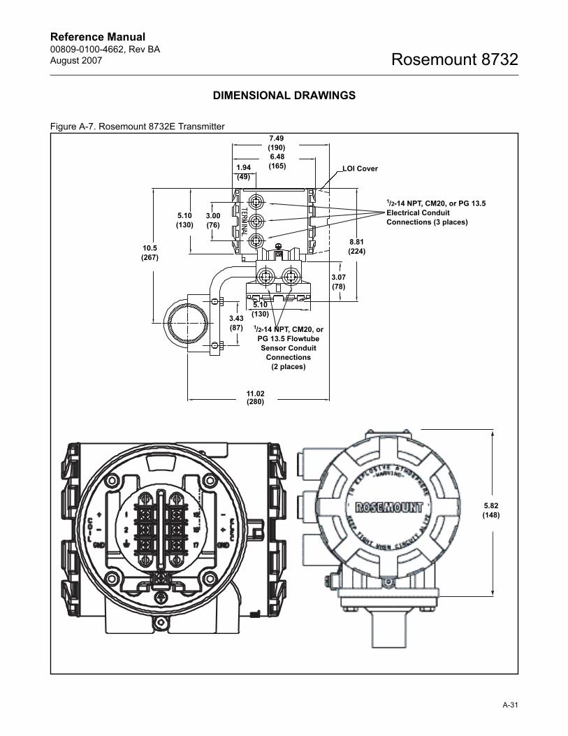
Reference Manual 00809-0100-4662, Rev BA
August 2007 Rosemount 8732
DIMENSIONAL DRAWINGS
Figure A-7. Rosemount 8732E Transmitter
1/2-14 NPT, CM20, or PG 13.5
Electrical Conduit
Connections (3 places)
LOI Cover
11.02(280)
1/2-14 NPT, CM20, or
PG 13.5 Flowtube
Sensor Conduit
Connections
(2 places)
10.5
(267)
5.82
(148)
5.10
(130)
5.10
(130)
7.49
(190)6.48
(165)1.94
(49)
8.81
(224)
3.07
(78)
3.00
(76)
3.43
(87)
A-31
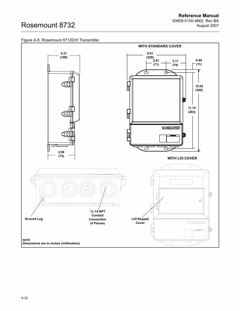
Reference Manual00809-0100-4662, Rev BA
August 2007Rosemount 8732
Figure A-8. Rosemount 8712D/H Transmitter
4.31
(109)
LOI Keypad
Cover
9.01
(229)
11.15
(283)
2.81
(71)3.11
(79)
12.02
(305)
0.44
(11)
Ground Lug
1/2–14 NPT
Conduit
Connection
(4 Places)
WITH STANDARD COVER
NOTEDimensions are in inches (millimeters)
2.96
(75)WITH LOI COVER
A-32
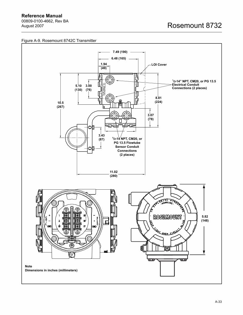
Reference Manual 00809-0100-4662, Rev BA
August 2007 Rosemount 8732
Figure A-9. Rosemount 8742C Transmitter
5.10
(130)
6.48 (165)
3.07
(78)
8.81
(224)
3.43
(87)
1/2-14” NPT, CM20, or PG 13.5 Electrical Conduit Connections (2 places)
1/2-14 NPT, CM20, or
PG 13.5 Flowtube
Sensor Conduit
Connections
(2 places)
7.49 (190)
1.94
(49)
3.00
(76)
LOI Cover
10.5
(267)
11.02
(280)
Note
Dimensions in inches (millimeters)
5.82
(148)
A-33
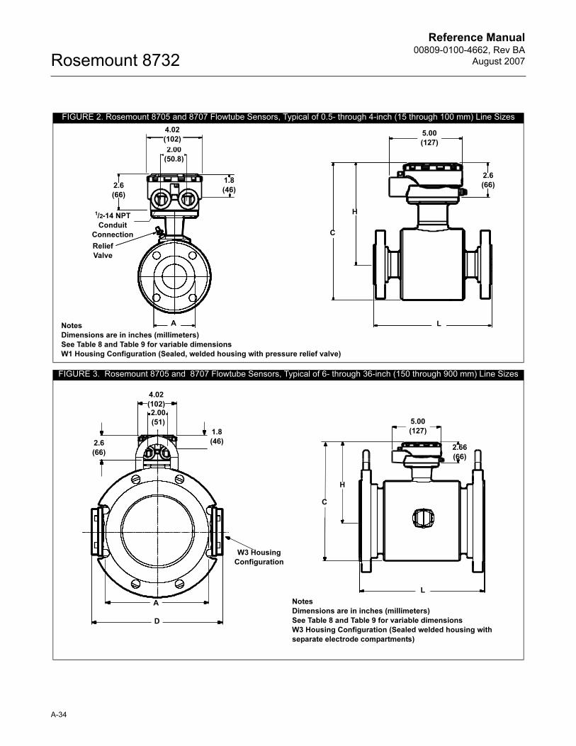
Reference Manual00809-0100-4662, Rev BA
August 2007Rosemount 8732
FIGURE 2. Rosemount 8705 and 8707 Flowtube Sensors, Typical of 0.5- through 4-inch (15 through 100 mm) Line Sizes
FIGURE 3. Rosemount 8705 and 8707 Flowtube Sensors, Typical of 6- through 36-inch (150 through 900 mm) Line Sizes
2.00
(50.8)
1.8
(46)
A
4.02
(102)
2.6
(66)
Relief
Valve
1/2-14 NPT
Conduit
Connection
5.00
(127)
2.6
(66)
H
L
C
Notes
Dimensions are in inches (millimeters)
See Table 8 and Table 9 for variable dimensions
W1 Housing Configuration (Sealed, welded housing with pressure relief valve)
A
1.8
(46)
4.02
(102)2.00
(51)
2.6
(66)
D
W3 Housing
Configuration
L
H
C
5.00
(127)
2.66
(66)
Notes
Dimensions are in inches (millimeters)
See Table 8 and Table 9 for variable dimensions
W3 Housing Configuration (Sealed welded housing with
separate electrode compartments)
A-34
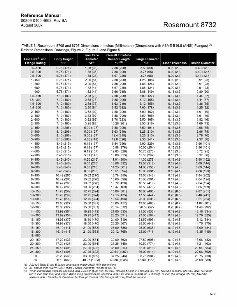
Reference Manual 00809-0100-4662, Rev BA
August 2007 Rosemount 8732
TABLE 8. Rosemount 8705 and 8707 Dimensions in Inches (Millimeters) (Dimensions with ASME B16.5 (ANSI) Flanges) (1)
Refer to Dimensional Drawings, Figure 2, Figure 3, and Figure 5
Line Size(2) and
Flange Rating
Body Height
“H”
Liner Face
Diameter
“A”
Overall Flowtube
Sensor Length
“L”(3)Flange Diameter
“D” Liner Thickness Inside Diameter
0.5–150
0.5–300
0.5–600
6.75 (171)
6.75 (171)
6.75 (171)
1.38 (35)
1.38 (35)
1.38 (35)
7.88 (200)
7.88 (200)
8.67 (220)
3.50 (89)
3.75 (95)
3.75 (95)
0.09 (2.3)
0.09 (2.3)
0.09 (2.3)
0.49 (12.5)
0.49 (12.5)
0.49 (12.5)
1–150
1–300
1–600
1–900
6.75 (171)
6.75 (171)
6.75 (171)
6.75 (171)
2.00 (51)
2.00 (51)
1.62 (41)
1.62 (41)
7.88 (200)
7.88 (200)
8.67 (220)
9.66 (245)
4.25 (108)
4.88 (124)
4.88 (124)
5.88 (149)
0.09 (2.3)
0.09 (2.3)
0.09 (2.3)
0.13 (3.3)
0.91 (23)
0.91 (23)
0.91 (23)
0.80 (20)
1.5–150
1.5 –300
1.5–600
1.5–900
7.10 (180)
7.10 (180)
7.10 (180)
7.10 (180)
2.88 (73)
2.88 (73)
2.88 (73)
2.50 (64)
7.88 (200)
7.88 (200)
8.63 (219)
9.52 (242)
5.00 (127)
6.12 (155)
6.12 (155)
7.00 (178)
0.12 (3.1)
0.12 (3.1)
0.13 (3.3)
0.13 (3.3)
1.44 (37)
1.44 (37)
1.36 (35)
1.25 (32)
2–150
2–300
2–600
2–900
7.10 (180)
7.10 (180)
7.10 (180)
7.10 (180)
3.62 (92)
3.62 (92)
3.62 (92)
3.25 (83)
7.88 (200)
7.88 (200)
8.78 (223)
10.26 (261)
6.00 (152)
6.50 (165)
6.50 (165)
8.50 (216)
0.12 (3.1)
0.12 (3.1)
0.13 (3.3)
0.13 (3.3)
1.91 (49)
1.91 (49)
1.82 (46)
1.69 (43)
3–150
3–300
3–600
3–900
8.10 (206)
8.10 (206)
8.10 (206)
8.10 (206)
5.00 (127)
5.00 (127)
5.00 (127)
4.63 (118)
7.88 (200)
8.63 (219)
12.4 (315)
12.8 (326)
7.50 (191)
8.25 (210)
8.25 (210)
9.50 (241)
0.15 (3.8)
0.15 (3.8)
0.13 (3.3)
0.13 (3.3)
2.96 (75)
2.96 (75)
2.76 (70)
2.37 (60)
4–150
4–300
4–600
4–900
8.45 (215)
8.45 (215)
8.45 (215)
8.45 (215)
6.19 (157)
6.19 (157)
6.19 (157)
5.81 (148)
9.84 (250)
10.88 (276)
12.83 (326)
13.89 (353)
9.00 (229)
10.00 (254)
10.75 (273)
11.50 (292)
0.15 (3.8)
0.15 (3.8)
0.13 (3.3)
0.13 (3.3)
3.96 (101)
3.96 (101)
3.72 (95)
3.37 (86)
6–150
6–300
6–600
6–900
9.45 (240)
9.45 (240)
9.45 (240)
9.45 (240)
8.50 (216)
8.50 (216)
8.50 (216)
8.00 (203)
11.81 (300)
13.06 (332)
14.23 (361)
15.51 (394)
11.00 (279)
12.50 (318)
14.00 (356)
15.00 (381)
0.19 (4.8)
0.19 (4.8)
0.19 (4.8)
0.16 (4.1)
5.98 (152)
5.69 (144)
5.69 (144)
4.86 (123)
8–150
8–300
8–600
8–900
10.42 (265)
10.42 (265)
10.42 (265)
10.42 (265)
10.62 (270)
10.62 (270)
10.62 (270)
10.00 (254)
13.78 (350)
15.60 (396)
16.72 (428)
18.47 (469)
13.50 (343)
15.00 (381)
16.50 (419)
18.50 (470)
0.19 (4.8)
0.17 (4.3)
0.17 (4.3)
0.17 (4.3)
7.94 (202)
7.64 (194)
7.64 (194)
6.65 (169)
10–150
10–300
10–600
11.78 (299)
11.78 (299)
11.78 (299)
12.75 (324)
12.75 (324)
12.75 (324)
15.00 (381)
17.13 (435)
19.54 (496)
16.00 (406)
17.50 (444)
20.00 (508)
0.26 (6.5)
0.26 (6.5)
0.26 (6.5)
9.87 (251)
9.48 (241)
9.21 (234)
12–150
12–300
12.86 (327)
12.86 (327)
15.00 (381)
15.00 (381)
18.00 (457)
20.14 (512)
19.00 (483)
20.50 (52)
0.26 (6.7)
0.26 (6.7)
11.87 (301)
11.48 (292)
14–150
14–300
13.92 (354)
13.92 (354)
16.25 (413)
16.25 (413)
21.00 (533)
23.25 (591)
21.00 (533)
23.00 (584)
0.19 (4.8)
0.19 (4.8)
13.16 (334)
12.79 (325)
16–150
16–300
14.93 (379)
14.93 (379)
18.50 (470)
18.50 (470)
24.00 (610)
26.25 (667)
23.50 (597)
25.50 (648)
0.19 (4.8)
0.19 (4.8)
15.12 (384)
14.75 (375)
18–150
18–300
18–450
16.19 (411)
16.19 (411)
21.00 (533)
21.00 (533)
27.00 (686)
30.12 (765)
25.00 (635)
28.00 (711)
0.19 (4.8)
0.19 (4.8)
17.09 (434)
16.35 (415)
20–150
20–300
17.20 (437)
17.20 (437)
23.00 (584)
23.00 (584)
30.00 (762)
33.25 (845)
27.50 (698)
30.50 (774)
0.19 (4.8)
0.19 (4.8)
18.96 (482)
18.21 (463)
24–150
24–300
19.48 (495)
19.48 (495)
27.25 (692)
27.25 (692)
36.00 (914)
39.64 (1007)
32.00 (813)
36.00 (914)
0.19 (4.8)
0.19 (4.8)
22.94 (583)
22.06 (560)
30
36
22.23 (565)
26.10 (663)
33.80 (859)
40.27 (1023)
37.25 (946)
40.88 (1038)
38.75 (984)
46.00 (1168)
0.19 (4.8)
0.19 (4.8)
28.75 (730)
35.00 (889)
(1) AS2129 Table D and E flange dimensions match ANSI 150# dimensions.(2) 30- and 36-inch AWWA C207 Table 2 Class D rated to 150 psi at 150 °F.(3) When 2 grounding rings are specified, add 0.25 inch (6.35 mm) for 0.50- through 14-inch (15 through 350 mm) flowtube sensors, add 0.50 inch (12.7 mm)
for 16-inch (400 mm) and larger. When lining protectors are specified, add 0.25 inch (6.35 mm) for ½- through 12-inch (15 through 300 mm) flowtube sensors, add 0.50 inch (12.7 mm) for 14- through 36-inch (350 through 900 mm) flowtube sensors.
A-35
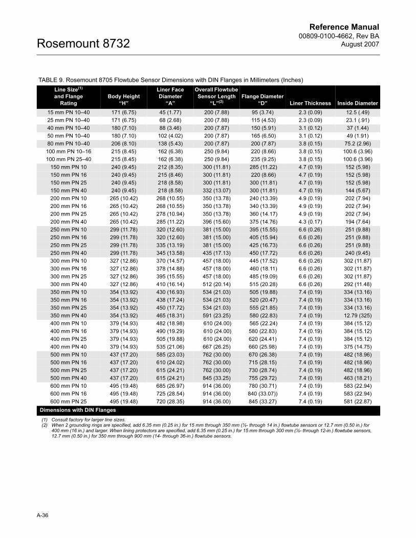
Reference Manual00809-0100-4662, Rev BA
August 2007Rosemount 8732
TABLE 9. Rosemount 8705 Flowtube Sensor Dimensions with DIN Flanges in Millimeters (Inches)
Line Size(1)
and Flange
Rating
Body Height
“H”
Liner Face
Diameter
“A”
Overall Flowtube
Sensor Length
“L”(2)Flange Diameter
“D” Liner Thickness Inside Diameter
15 mm PN 10–40 171 (6.75) 45 (1.77) 200 (7.88) 95 (3.74) 2.3 (0.09) 12.5 (.49)
25 mm PN 10–40 171 (6.75) 68 (2.68) 200 (7.88) 115 (4.53) 2.3 (0.09) 23.1 (.91)
40 mm PN 10–40 180 (7.10) 88 (3.46) 200 (7.87) 150 (5.91) 3.1 (0.12) 37 (1.44)
50 mm PN 10–40 180 (7.10) 102 (4.02) 200 (7.87) 165 (6.50) 3.1 (0.12) 49 (1.91)
80 mm PN 10–40 206 (8.10) 138 (5.43) 200 (7.87) 200 (7.87) 3.8 (0.15) 75.2 (2.96)
100 mm PN 10–16 215 (8.45) 162 (6.38) 250 (9.84) 220 (8.66) 3.8 (0.15) 100.6 (3.96)
100 mm PN 25–40 215 (8.45) 162 (6.38) 250 (9.84) 235 (9.25) 3.8 (0.15) 100.6 (3.96)
150 mm PN 10 240 (9.45) 212 (8.35) 300 (11.81) 285 (11.22) 4.7 (0.19) 152 (5.98)
150 mm PN 16 240 (9.45) 215 (8.46) 300 (11.81) 220 (8.66) 4.7 (0.19) 152 (5.98)
150 mm PN 25 240 (9.45) 218 (8.58) 300 (11.81) 300 (11.81) 4.7 (0.19) 152 (5.98)
150 mm PN 40 240 (9.45) 218 (8.58) 332 (13.07) 300 (11.81) 4.7 (0.19) 144 (5.67)
200 mm PN 10 265 (10.42) 268 (10.55) 350 (13.78) 240 (13.39) 4.9 (0.19) 202 (7.94)
200 mm PN 16 265 (10.42) 268 (10.55) 350 (13.78) 340 (13.39) 4.9 (0.19) 202 (7.94)
200 mm PN 25 265 (10.42) 278 (10.94) 350 (13.78) 360 (14.17) 4.9 (0.19) 202 (7.94)
200 mm PN 40 265 (10.42) 285 (11.22) 396 (15.60) 375 (14.76) 4.3 (0.17) 194 (7.64)
250 mm PN 10 299 (11.78) 320 (12.60) 381 (15.00) 395 (15.55) 6.6 (0.26) 251 (9.88)
250 mm PN 16 299 (11.78) 320 (12.60) 381 (15.00) 405 (15.94) 6.6 (0.26) 251 (9.88)
250 mm PN 25 299 (11.78) 335 (13.19) 381 (15.00) 425 (16.73) 6.6 (0.26) 251 (9.88)
250 mm PN 40 299 (11.78) 345 (13.58) 435 (17.13) 450 (17.72) 6.6 (0.26) 240 (9.45)
300 mm PN 10 327 (12.86) 370 (14.57) 457 (18.00) 445 (17.52) 6.6 (0.26) 302 (11.87)
300 mm PN 16 327 (12.86) 378 (14.88) 457 (18.00) 460 (18.11) 6.6 (0.26) 302 (11.87)
300 mm PN 25 327 (12.86) 395 (15.55) 457 (18.00) 485 (19.09) 6.6 (0.26) 302 (11.87)
300 mm PN 40 327 (12.86) 410 (16.14) 512 (20.14) 515 (20.28) 6.6 (0.26) 292 (11.48)
350 mm PN 10 354 (13.92) 430 (16.93) 534 (21.03) 505 (19.88) 7.4 (0.19) 334 (13.16)
350 mm PN 16 354 (13.92) 438 (17.24) 534 (21.03) 520 (20.47) 7.4 (0.19) 334 (13.16)
350 mm PN 25 354 (13.92) 450 (17.72) 534 (21.03) 555 (21.85) 7.4 (0.19) 334 (13.16)
350 mm PN 40 354 (13.92) 465 (18.31) 591 (23.25) 580 (22.83) 7.4 (0.19) 12.79 (325)
400 mm PN 10 379 (14.93) 482 (18.98) 610 (24.00) 565 (22.24) 7.4 (0.19) 384 (15.12)
400 mm PN 16 379 (14.93) 490 (19.29) 610 (24.00) 580 (22.83) 7.4 (0.19) 384 (15.12)
400 mm PN 25 379 (14.93) 505 (19.88) 610 (24.00) 620 (24.41) 7.4 (0.19) 384 (15.12)
400 mm PN 40 379 (14.93) 535 (21.06) 667 (26.25) 660 (25.98) 7.4 (0.19) 375 (14.75)
500 mm PN 10 437 (17.20) 585 (23.03) 762 (30.00) 670 (26.38) 7.4 (0.19) 482 (18.96)
500 mm PN 16 437 (17.20) 610 (24.02) 762 (30.00) 715 (28.15) 7.4 (0.19) 482 (18.96)
500 mm PN 25 437 (17.20) 615 (24.21) 762 (30.00) 730 (28.74) 7.4 (0.19) 482 (18.96)
500 mm PN 40 437 (17.20) 615 (24.21) 845 (33.25) 755 (29.72) 7.4 (0.19) 463 (18.21)
600 mm PN 10 495 (19.48) 685 (26.97) 914 (36.00) 780 (30.71) 7.4 (0.19) 583 (22.94)
600 mm PN 16 495 (19.48) 725 (28.54) 914 (36.00) 840 (33.07)) 7.4 (0.19) 583 (22.94)
600 mm PN 25 495 (19.48) 720 (28.35) 914 (36.00) 845 (33.27) 7.4 (0.19) 581 (22.87)
Dimensions with DIN Flanges
(1) Consult factory for larger line sizes.(2) When 2 grounding rings are specified, add 6.35 mm (0.25 in.) for 15 mm through 350 mm (½- through 14 in.) flowtube sensors or 12.7 mm (0.50 in.) for
400 mm (16 in.) and larger. When lining protectors are specified, add 6.35 mm (0.25 in.) for 15 mm through 300 mm (½- through 12-in.) flowtube sensors, 12.7 mm (0.50 in.) for 350 mm through 900 mm (14- through 36-in.) flowtube sensors.
A-36
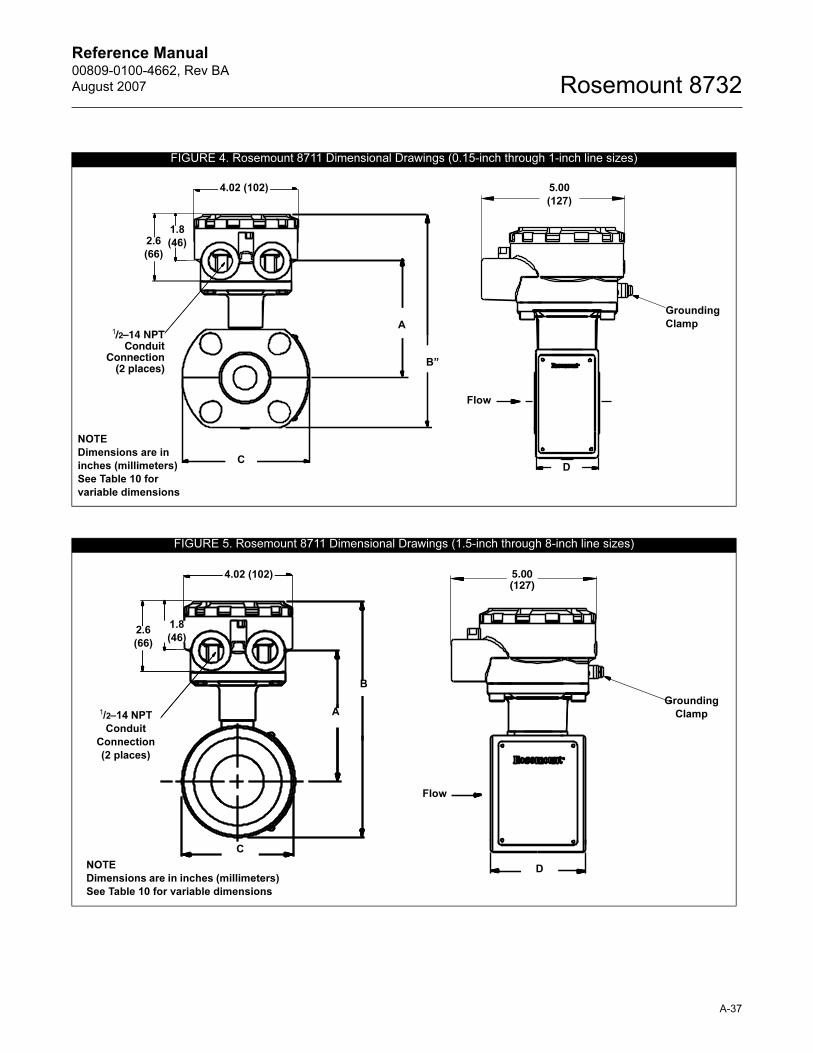
Reference Manual 00809-0100-4662, Rev BA
August 2007 Rosemount 8732
FIGURE 4. Rosemount 8711 Dimensional Drawings (0.15-inch through 1-inch line sizes)
A
B”
Flow
5.00
(127)
D
Grounding
Clamp1/2–14 NPT
ConduitConnection
(2 places)
C
NOTE
Dimensions are in
inches (millimeters)
See Table 10 for
variable dimensions
2.6
(66)
1.8
(46)
4.02 (102)
FIGURE 5. Rosemount 8711 Dimensional Drawings (1.5-inch through 8-inch line sizes)
B
A
2.6
(66)
1.8
(46)
4.02 (102) 5.00 (127)
NOTE
Dimensions are in inches (millimeters)
See Table 10 for variable dimensions
Flow
D
Grounding
Clamp
C
1/2–14 NPT
Conduit
Connection
(2 places)
A-37
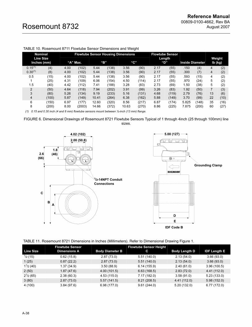
Reference Manual00809-0100-4662, Rev BA
August 2007Rosemount 8732
FIGURE 6. Dimensional Drawings of Rosemount 8721 Flowtube Sensors Typical of 1 through 4inch (25 through 100mm) line sizes.
TABLE 10. Rosemount 8711 Flowtube Sensor Dimensions and Weight
Nominal
Line Size
Inches (mm)
Flowtube Sensor Housing Dimensions Flowtube Sensor
Length
“D” Inside Diameter
Weight
lb (kg)“A” Max. “B” “C”
0.15(1)
0.30(1)
(4)
(8)
4.00
4.00
(102)
(102)
5.44
5.44
(138)
(138)
3.56
3.56
(90)
(90)
2.17
2.17
(55)
(55)
.150
.300
(4)
(7)
4
4
(2)
(2)
0.5
1
1.5
(15)
(25)
(40)
4.00
4.31
4.42
(102)
(109)
(112)
5.44
6.06
7.41
(138)
(154)
(188)
3.56
4.50
3.28
(90)
(114)
(83)
2.17
2.17
2.73
(55)
(55)
(69)
.593
.970
1.50
(15)
(24)
(38)
4
5
5
(2)
(2)
(2)
2
3
4
(50)
(80)
(100)
4.64
5.26
5.87
(118)
(134)
(149)
7.94
9.19
10.41
(202)
(233)
(264)
3.91
5.16
6.38
(99)
(131)
(162)
3.26
4.68
5.88
(83)
(119)
(149)
1.92
2.79
3.70
(50)
(76)
(99)
7
13
22
(3)
(6)
(10)
6
8
(150)
(200)
6.97
8.00
(177)
(2003)
12.60
14.66
(320)
(372)
8.56
10.63
(217)
(270)
6.87
8.86
(174)
(225)
5.825
7.875
(148)
(200)
35
60
(16)
(27)
(1) 0.15 and 0.30 inch (4 and 8 mm) flowtube sensors mount between ½-inch (13 mm) flange.
4.02 (102)
2.00 (50.8)
1.8
(46)2.6
(66)
C
BA
1/2-14NPT Conduit
Connections
5.00 (127)
Grounding Clamp
D
E
IDF Code B
TABLE 11. Rosemount 8721 Dimensions in Inches (Millimeters). Refer to Dimensional Drawing Figure 1.
Line Size
Flowtube Sensor
Dimensions A Body Diameter B
Flowtube Sensor Height
C Body Length D IDF Length E
1/2 (15) 0.62 (15.8) 2.87 (73.0) 5.51 (140.0) 2.13 (54.0) 3.66 (93.0)
1 (25) 0.87 (22.2) 2.87 (73.0) 5.51 (140.0) 2.13 (54.0) 3.66 (93.0)
11/2 (40) 1.37 (34.9) 3.50 (88.9) 6.14 (155.9) 2.40 (61.0) 3.96 (100.5)
2 (50) 1.87 (47.6) 4.00 (101.5) 6.63 (168.5) 2.83 (72.0) 4.41 (112.0)
21/2 (65) 2.38 (60.3) 4.53 (115.0) 7.17 (182.0) 3.58 (91.0) 5.23 (133.0)
3 (80) 2.87 (73.0) 5.57 (141.5) 8.21 (208.5) 4.41 (112.0) 5.98 (152.0)
4 (100) 3.84 (97.6) 6.98 (177.0) 9.61 (244.0) 5.20 (132.0) 6.77 (172.0)
A-38
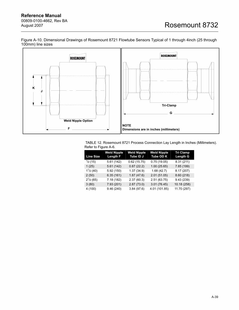
Reference Manual 00809-0100-4662, Rev BA
August 2007 Rosemount 8732
Figure A-10. Dimensional Drawings of Rosemount 8721 Flowtube Sensors Typical of 1 through 4inch (25 through 100mm) line sizes
F
JK
Weld Nipple Option
G
NOTE
Dimensions are in inches (millimeters)
Tri-Clamp
TABLE 12. Rosemount 8721 Process Connection Lay Length in Inches (Millimeters).
Refer to Figure A-6.
Line Size
Weld Nipple
Length F
Weld Nipple
Tube ID J
Weld Nipple
Tube OD K
Tri Clamp
Length G
1/2 (15) 5.61 (142) 0.62 (15.75) 0.75 (19.05) 8.31 (211)
1 (25) 5.61 (142) 0.87 (22.2) 1.00 (25.65) 7.85 (199)
11/2 (40) 5.92 (150) 1.37 (34.9) 1.68 (42.7) 8.17 (207)
2 (50) 6.35 (161) 1.87 (47.6) 2.01 (51.05) 8.60 (218)
21/2 (65) 7.18 (182) 2.37 (60.3) 2.51 (63.75) 9.43 (239)
3 (80) 7.93 (201) 2.87 (73.0) 3.01 (76.45) 10.18 (258)
4 (100) 9.46 (240) 3.84 (97.6) 4.01 (101.85) 11.70 (297)
A-39
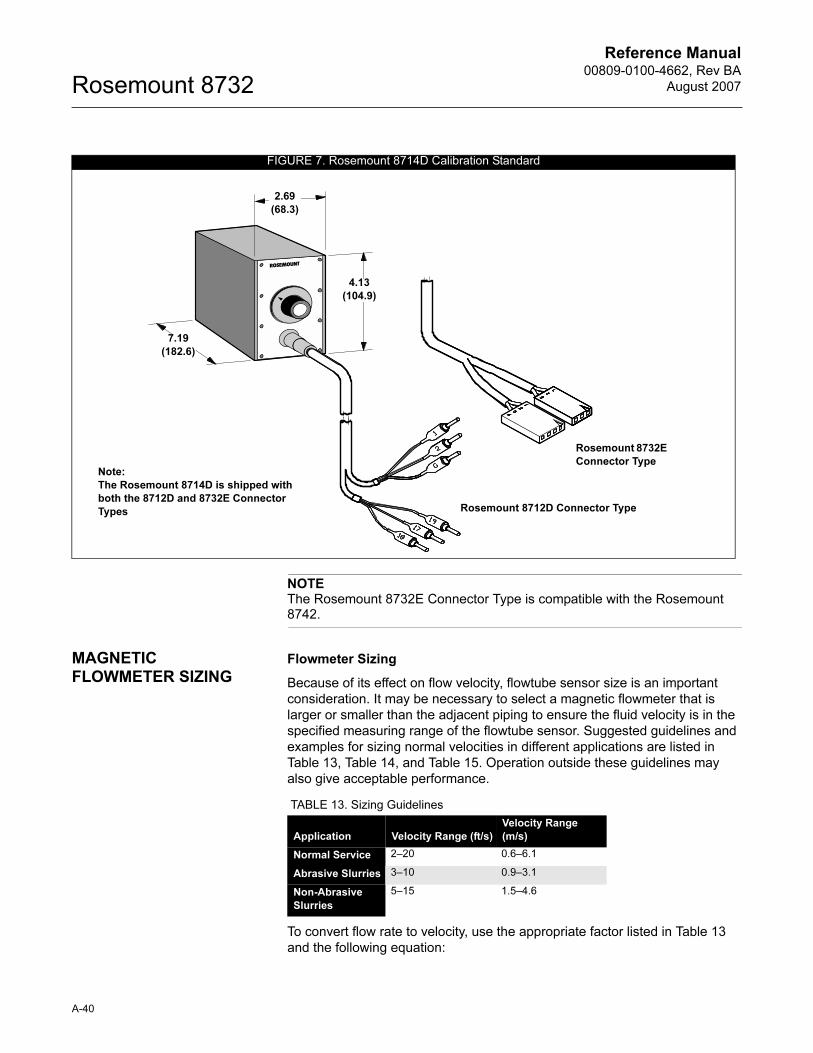
Reference Manual00809-0100-4662, Rev BA
August 2007Rosemount 8732
NOTEThe Rosemount 8732E Connector Type is compatible with the Rosemount 8742.
MAGNETIC FLOWMETER SIZING
Flowmeter Sizing
Because of its effect on flow velocity, flowtube sensor size is an important
consideration. It may be necessary to select a magnetic flowmeter that is
larger or smaller than the adjacent piping to ensure the fluid velocity is in the
specified measuring range of the flowtube sensor. Suggested guidelines and
examples for sizing normal velocities in different applications are listed in
Table 13, Table 14, and Table 15. Operation outside these guidelines may
also give acceptable performance.
To convert flow rate to velocity, use the appropriate factor listed in Table 13
and the following equation:
FIGURE 7. Rosemount 8714D Calibration Standard
2.69
(68.3)
4.13
(104.9)
7.19
(182.6)
Rosemount 8732E
Connector Type
Rosemount 8712D Connector Type
Note:
The Rosemount 8714D is shipped with
both the 8712D and 8732E Connector
Types
TABLE 13. Sizing Guidelines
Application Velocity Range (ft/s)
Velocity Range
(m/s)
Normal Service 2–20 0.6–6.1
Abrasive Slurries 3–10 0.9–3.1
Non-Abrasive
Slurries
5–15 1.5–4.6
A-40
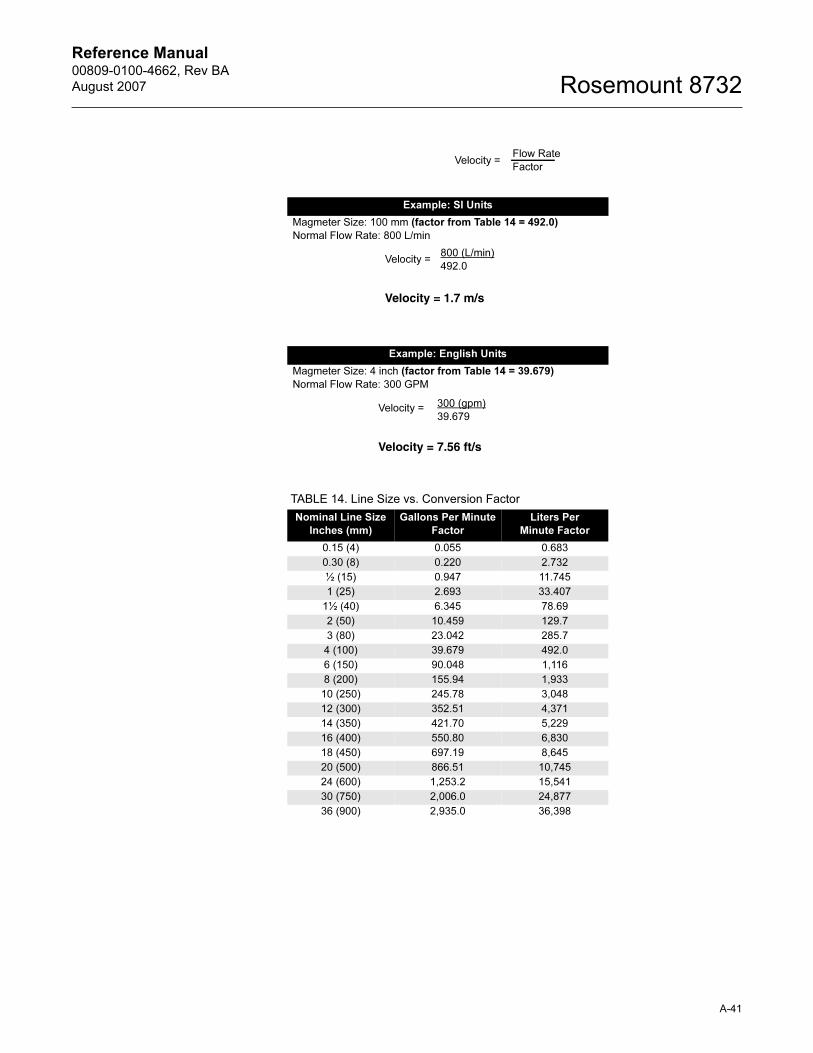
Reference Manual 00809-0100-4662, Rev BA
August 2007 Rosemount 8732
Example: SI Units
Magmeter Size: 100 mm (factor from Table 14 = 492.0)
Normal Flow Rate: 800 L/min
Example: English Units
Magmeter Size: 4 inch (factor from Table 14 = 39.679)
Normal Flow Rate: 300 GPM
TABLE 14. Line Size vs. Conversion Factor
Nominal Line Size
Inches (mm)
Gallons Per Minute
Factor
Liters Per
Minute Factor
0.15 (4) 0.055 0.683
0.30 (8) 0.220 2.732
½ (15) 0.947 11.745
1 (25) 2.693 33.407
1½ (40) 6.345 78.69
2 (50) 10.459 129.7
3 (80) 23.042 285.7
4 (100) 39.679 492.0
6 (150) 90.048 1,116
8 (200) 155.94 1,933
10 (250) 245.78 3,048
12 (300) 352.51 4,371
14 (350) 421.70 5,229
16 (400) 550.80 6,830
18 (450) 697.19 8,645
20 (500) 866.51 10,745
24 (600) 1,253.2 15,541
30 (750) 2,006.0 24,877
36 (900) 2,935.0 36,398
Velocity =Flow Rate
Factor
Velocity =
Velocity = 1.7 m/s
800 (L/min)
492.0
Velocity =
Velocity = 7.56 ft/s
300 (gpm)
39.679
A-41
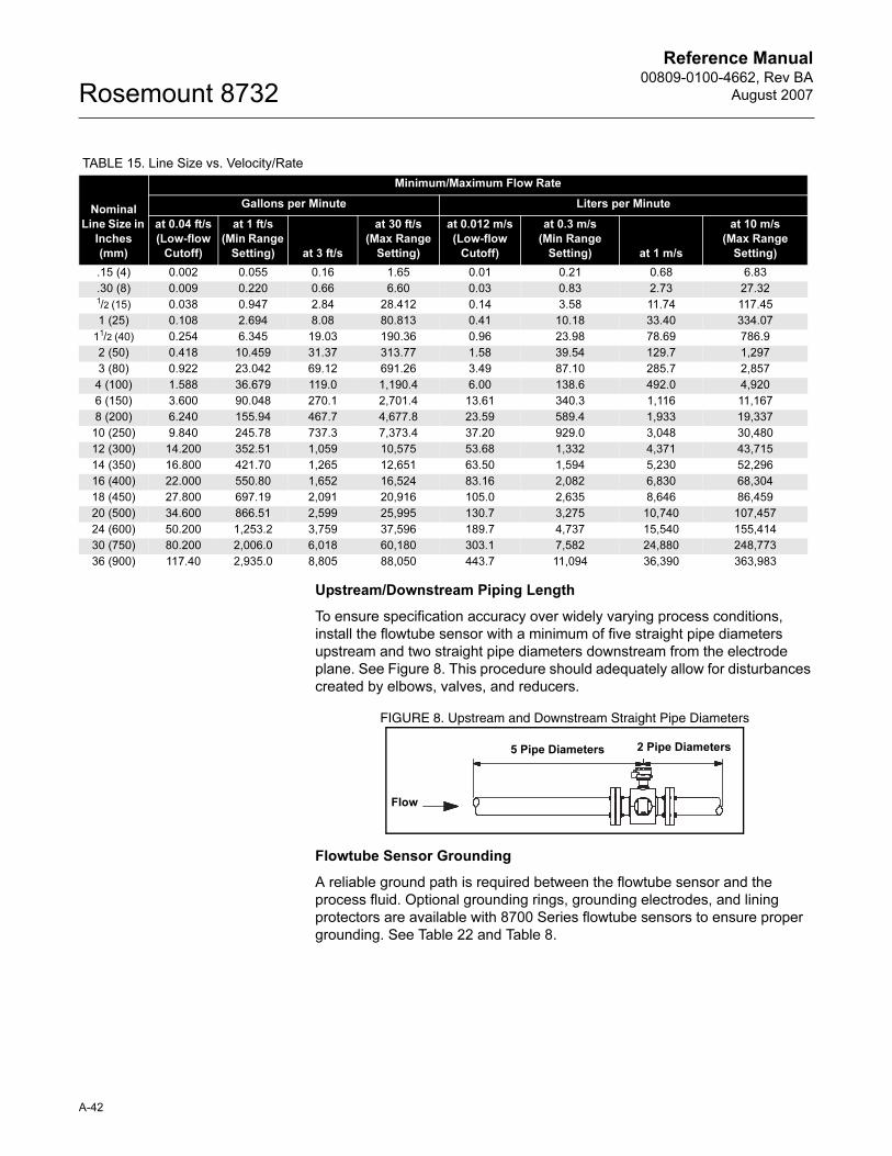
Reference Manual00809-0100-4662, Rev BA
August 2007Rosemount 8732
Upstream/Downstream Piping Length
To ensure specification accuracy over widely varying process conditions,
install the flowtube sensor with a minimum of five straight pipe diameters
upstream and two straight pipe diameters downstream from the electrode
plane. See Figure 8. This procedure should adequately allow for disturbances
created by elbows, valves, and reducers.
FIGURE 8. Upstream and Downstream Straight Pipe Diameters
Flowtube Sensor Grounding
A reliable ground path is required between the flowtube sensor and the
process fluid. Optional grounding rings, grounding electrodes, and lining
protectors are available with 8700 Series flowtube sensors to ensure proper
grounding. See Table 22 and Table 8.
TABLE 15. Line Size vs. Velocity/Rate
Nominal
Line Size in
Inches
(mm)
Minimum/Maximum Flow Rate
Gallons per Minute Liters per Minute
at 0.04 ft/s
(Low-flow
Cutoff)
at 1 ft/s
(Min Range
Setting) at 3 ft/s
at 30 ft/s
(Max Range
Setting)
at 0.012 m/s
(Low-flow
Cutoff)
at 0.3 m/s
(Min Range
Setting) at 1 m/s
at 10 m/s
(Max Range
Setting)
.15 (4) 0.002 0.055 0.16 1.65 0.01 0.21 0.68 6.83
.30 (8) 0.009 0.220 0.66 6.60 0.03 0.83 2.73 27.321/2 (15) 0.038 0.947 2.84 28.412 0.14 3.58 11.74 117.45
1 (25) 0.108 2.694 8.08 80.813 0.41 10.18 33.40 334.07
11/2 (40) 0.254 6.345 19.03 190.36 0.96 23.98 78.69 786.9
2 (50) 0.418 10.459 31.37 313.77 1.58 39.54 129.7 1,297
3 (80) 0.922 23.042 69.12 691.26 3.49 87.10 285.7 2,857
4 (100) 1.588 36.679 119.0 1,190.4 6.00 138.6 492.0 4,920
6 (150) 3.600 90.048 270.1 2,701.4 13.61 340.3 1,116 11,167
8 (200) 6.240 155.94 467.7 4,677.8 23.59 589.4 1,933 19,337
10 (250) 9.840 245.78 737.3 7,373.4 37.20 929.0 3,048 30,480
12 (300) 14.200 352.51 1,059 10,575 53.68 1,332 4,371 43,715
14 (350) 16.800 421.70 1,265 12,651 63.50 1,594 5,230 52,296
16 (400) 22.000 550.80 1,652 16,524 83.16 2,082 6,830 68,304
18 (450) 27.800 697.19 2,091 20,916 105.0 2,635 8,646 86,459
20 (500) 34.600 866.51 2,599 25,995 130.7 3,275 10,740 107,457
24 (600) 50.200 1,253.2 3,759 37,596 189.7 4,737 15,540 155,414
30 (750) 80.200 2,006.0 6,018 60,180 303.1 7,582 24,880 248,773
36 (900) 117.40 2,935.0 8,805 88,050 443.7 11,094 36,390 363,983
Flow
5 Pipe Diameters 2 Pipe Diameters
A-42
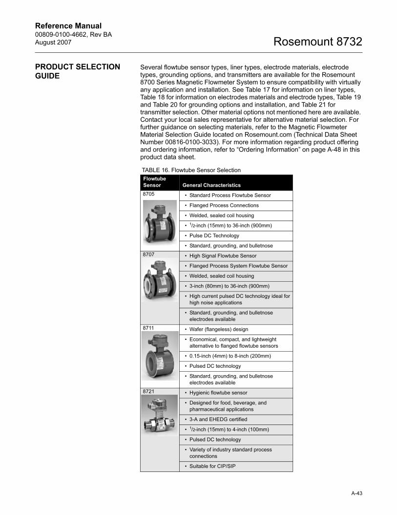
Reference Manual 00809-0100-4662, Rev BA
August 2007 Rosemount 8732
PRODUCT SELECTION GUIDE
Several flowtube sensor types, liner types, electrode materials, electrode types, grounding options, and transmitters are available for the Rosemount 8700 Series Magnetic Flowmeter System to ensure compatibility with virtually any application and installation. See Table 17 for information on liner types, Table 18 for information on electrodes materials and electrode types, Table 19 and Table 20 for grounding options and installation, and Table 21 for transmitter selection. Other material options not mentioned here are available. Contact your local sales representative for alternative material selection. For further guidance on selecting materials, refer to the Magnetic Flowmeter Material Selection Guide located on Rosemount.com (Technical Data Sheet Number 00816-0100-3033). For more information regarding product offering and ordering information, refer to “Ordering Information” on page A-48 in this product data sheet.
TABLE 16. Flowtube Sensor Selection
Flowtube
Sensor General Characteristics
8705 • Standard Process Flowtube Sensor
• Flanged Process Connections
• Welded, sealed coil housing
• 1/2-inch (15mm) to 36-inch (900mm)
• Pulse DC Technology
• Standard, grounding, and bulletnose
8707 • High Signal Flowtube Sensor
• Flanged Process System Flowtube Sensor
• Welded, sealed coil housing
• 3-inch (80mm) to 36-inch (900mm)
• High current pulsed DC technology ideal for
high noise applications
• Standard, grounding, and bulletnose
electrodes available
8711 • Wafer (flangeless) design
• Economical, compact, and lightweight
alternative to flanged flowtube sensors
• 0.15-inch (4mm) to 8-inch (200mm)
• Pulsed DC technology
• Standard, grounding, and bulletnose
electrodes available
8721 • Hygienic flowtube sensor
• Designed for food, beverage, and
pharmaceutical applications
• 3-A and EHEDG certified
• 1/2-inch (15mm) to 4-inch (100mm)
• Pulsed DC technology
• Variety of industry standard process
connections
• Suitable for CIP/SIP
A-43
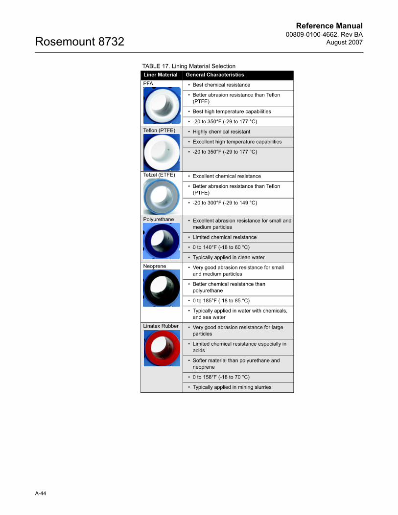
Reference Manual00809-0100-4662, Rev BA
August 2007Rosemount 8732
TABLE 17. Lining Material Selection
Liner Material General Characteristics
PFA • Best chemical resistance
• Better abrasion resistance than Teflon
(PTFE)
• Best high temperature capabilities
• -20 to 350°F (-29 to 177 °C)
Teflon (PTFE) • Highly chemical resistant
• Excellent high temperature capabilities
• -20 to 350°F (-29 to 177 °C)
Tefzel (ETFE) • Excellent chemical resistance
• Better abrasion resistance than Teflon
(PTFE)
• -20 to 300°F (-29 to 149 °C)
Polyurethane • Excellent abrasion resistance for small and
medium particles
• Limited chemical resistance
• 0 to 140°F (-18 to 60 °C)
• Typically applied in clean water
Neoprene • Very good abrasion resistance for small
and medium particles
• Better chemical resistance than
polyurethane
• 0 to 185°F (-18 to 85 °C)
• Typically applied in water with chemicals,
and sea water
Linatex Rubber • Very good abrasion resistance for large
particles
• Limited chemical resistance especially in
acids
• Softer material than polyurethane and
neoprene
• 0 to 158°F (-18 to 70 °C)
• Typically applied in mining slurries
A-44
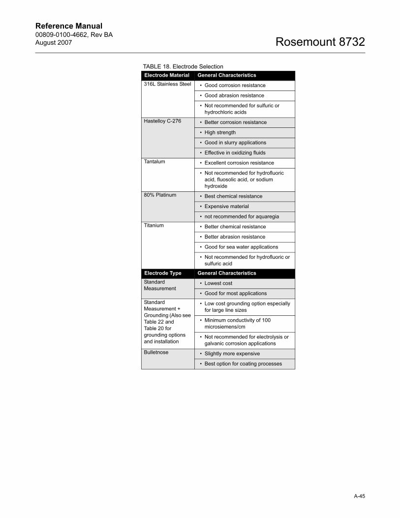
Reference Manual 00809-0100-4662, Rev BA
August 2007 Rosemount 8732
TABLE 18. Electrode Selection
Electrode Material General Characteristics
316L Stainless Steel • Good corrosion resistance
• Good abrasion resistance
• Not recommended for sulfuric or
hydrochloric acids
Hastelloy C-276 • Better corrosion resistance
• High strength
• Good in slurry applications
• Effective in oxidizing fluids
Tantalum • Excellent corrosion resistance
• Not recommended for hydrofluoric
acid, fluosolic acid, or sodium
hydroxide
80% Platinum • Best chemical resistance
• Expensive material
• not recommended for aquaregia
Titanium • Better chemical resistance
• Better abrasion resistance
• Good for sea water applications
• Not recommended for hydrofluoric or
sulfuric acid
Electrode Type General Characteristics
Standard
Measurement• Lowest cost
• Good for most applications
Standard
Measurement +
Grounding (Also see
Table 22 and
Table 20 for
grounding options
and installation
• Low cost grounding option especially
for large line sizes
• Minimum conductivity of 100
microsiemens/cm
• Not recommended for electrolysis or
galvanic corrosion applications
Bulletnose • Slightly more expensive
• Best option for coating processes
A-45
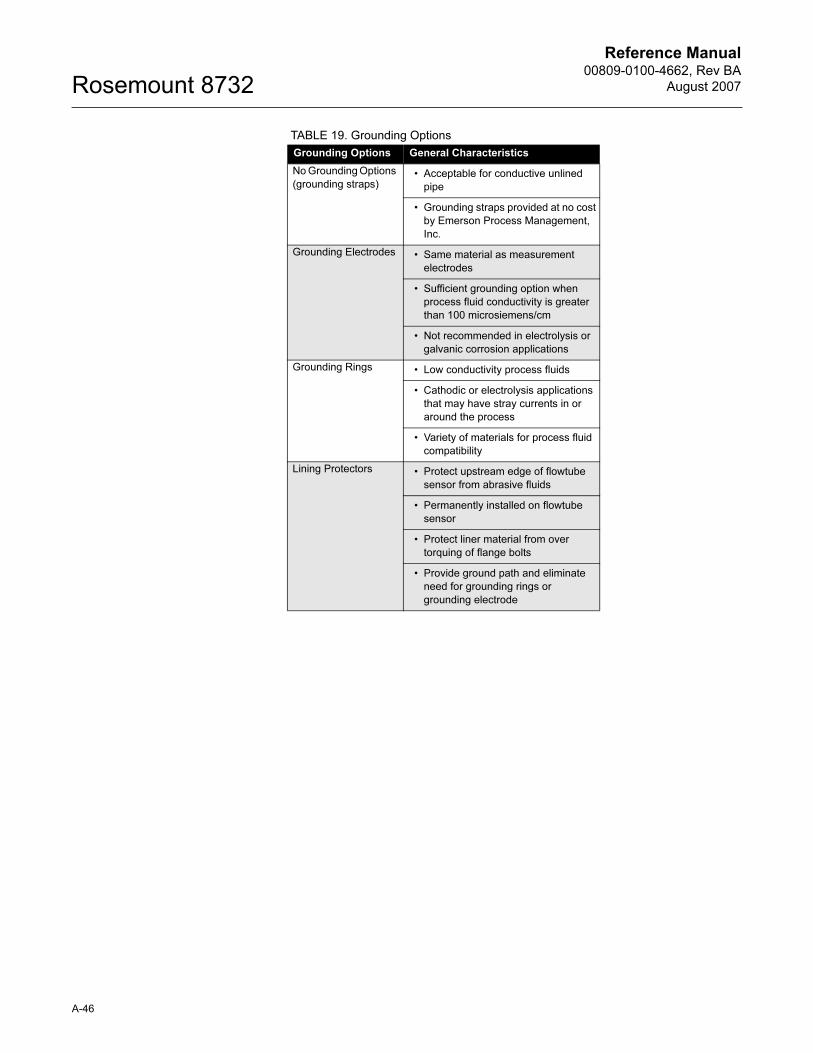
Reference Manual00809-0100-4662, Rev BA
August 2007Rosemount 8732
TABLE 19. Grounding Options
Grounding Options General Characteristics
No Grounding Options
(grounding straps)• Acceptable for conductive unlined
pipe
• Grounding straps provided at no cost
by Emerson Process Management,
Inc.
Grounding Electrodes • Same material as measurement
electrodes
• Sufficient grounding option when
process fluid conductivity is greater
than 100 microsiemens/cm
• Not recommended in electrolysis or
galvanic corrosion applications
Grounding Rings • Low conductivity process fluids
• Cathodic or electrolysis applications
that may have stray currents in or
around the process
• Variety of materials for process fluid
compatibility
Lining Protectors • Protect upstream edge of flowtube
sensor from abrasive fluids
• Permanently installed on flowtube
sensor
• Protect liner material from over
torquing of flange bolts
• Provide ground path and eliminate
need for grounding rings or
grounding electrode
A-46
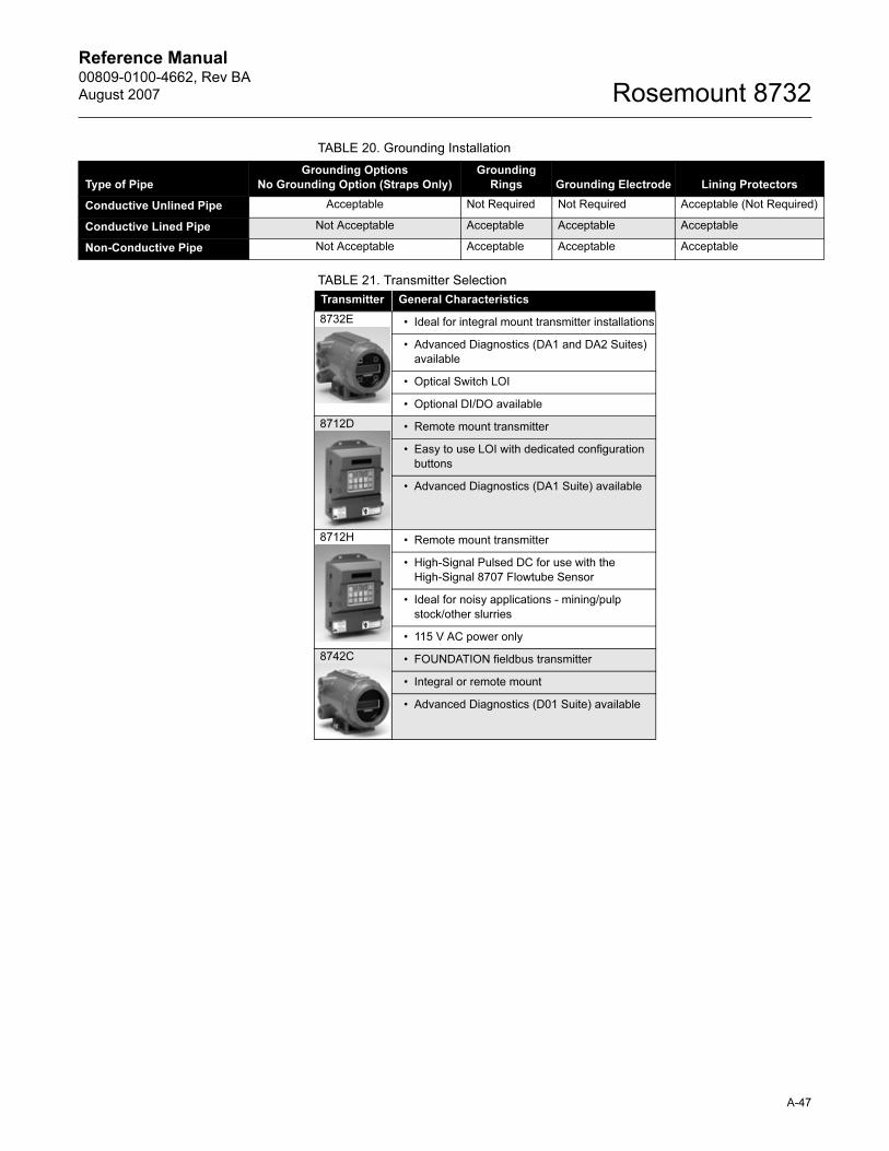
Reference Manual 00809-0100-4662, Rev BA
August 2007 Rosemount 8732
TABLE 20. Grounding Installation
TABLE 21. Transmitter Selection
Type of Pipe
Grounding Options
No Grounding Option (Straps Only)
Grounding
Rings Grounding Electrode Lining Protectors
Conductive Unlined Pipe Acceptable Not Required Not Required Acceptable (Not Required)
Conductive Lined Pipe Not Acceptable Acceptable Acceptable Acceptable
Non-Conductive Pipe Not Acceptable Acceptable Acceptable Acceptable
Transmitter General Characteristics
8732E • Ideal for integral mount transmitter installations
• Advanced Diagnostics (DA1 and DA2 Suites)
available
• Optical Switch LOI
• Optional DI/DO available
8712D • Remote mount transmitter
• Easy to use LOI with dedicated configuration
buttons
• Advanced Diagnostics (DA1 Suite) available
8712H • Remote mount transmitter
• High-Signal Pulsed DC for use with the
High-Signal 8707 Flowtube Sensor
• Ideal for noisy applications - mining/pulp
stock/other slurries
• 115 V AC power only
8742C • FOUNDATION fieldbus transmitter
• Integral or remote mount
• Advanced Diagnostics (D01 Suite) available
A-47
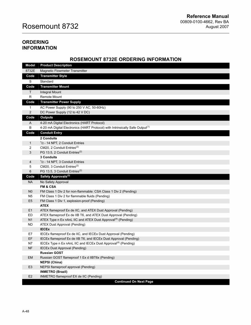
Reference Manual00809-0100-4662, Rev BA
August 2007Rosemount 8732
ORDERING INFORMATION
ROSEMOUNT 8732E ORDERING INFORMATIONModel Product Description
8732E Magnetic Flowmeter Transmitter
Code Transmitter Style
S Standard
Code Transmitter Mount
T Integral Mount
R Remote Mount
Code Transmitter Power Supply
1 AC Power Supply (90 to 250 V AC, 50-60Hz)
2 DC Power Supply (12 to 42 V DC)
Code Outputs
A 4-20 mA Digital Electronics (HART Protocol)
B 4-20 mA Digital Electronics (HART Protocol) with Intrinsically Safe Output(1)
Code Conduit Entry
2 Conduits
1 1/2 - 14 NPT, 2 Conduit Entries
2 CM20, 2 Conduit Entries(2)
3 PG 13.5, 2 Conduit Entries(2)
3 Conduits
4 1/2 - 14 NPT, 3 Conduit Entries
5 CM20, 3 Conduit Entries(2)
6 PG 13.5, 3 Conduit Entries(2)
Code Safety Approvals(3)
NA No Safety Approval
FM & CSA
N0 FM Class 1 Div 2 for non-flammable: CSA Class 1 Div 2 (Pending)
N5 FM Class 1 Div 2 for flammable fluids (Pending)
E5 FM Class 1 Div 1, explosion-proof (Pending)
ATEX
E1 ATEX flameproof Ex de IIC, and ATEX Dust Approval (Pending)
ED ATEX flameproof Ex de IIB T6, and ATEX Dust Approval (Pending)
N1 ATEX Type n Ex nAnL IIC and ATEX Dust Approval(4) (Pending)
ND ATEX Dust Approval (Pending)
IECEx
E7 IECEx flameproof Ex de IIC, and IECEx Dust Approval (Pending)
EF IECEx flameproof Ex de IIB T6, and IECEx Dust Approval (Pending)
N7 IECEx Type n Ex nAnL IIC and IECEx Dust Approval(4) (Pending)
NF IECEx Dust Approval (Pending)
Russian GOST
EM Russian GOST flameproof 1 Ex d IIBT6x (Pending)
NEPSI (China)
E3 NEPSI flameproof approval (Pending)
INMETRO (Brazil)
E2 INMETRO flameproof EX de IIC (Pending)
Continued On Next Page
A-48
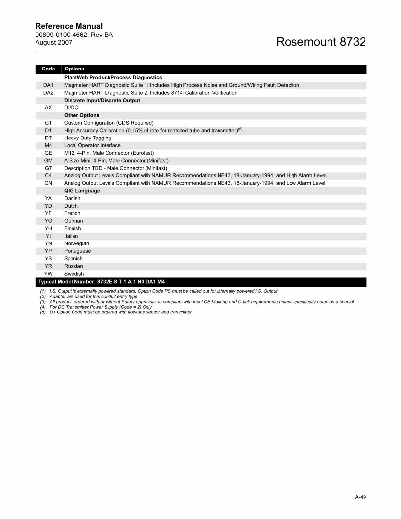
Reference Manual 00809-0100-4662, Rev BA
August 2007 Rosemount 8732
Code Options
PlantWeb Product/Process Diagnostics
DA1 Magmeter HART Diagnostic Suite 1: Includes High Process Noise and Ground/Wiring Fault Detection
DA2 Magmeter HART Diagnostic Suite 2: Includes 8714i Calibration Verification
Discrete Input/Discrete Output
AX DI/DO
Other Options
C1 Custom Configuration (CDS Required)
D1 High Accuracy Calibration (0.15% of rate for matched tube and transmitter)(5)
DT Heavy Duty Tagging
M4 Local Operator Interface
GE M12, 4-Pin, Male Connector (Eurofast)
GM A Size Mini, 4-Pin, Male Connector (Minifast)
GT Description TBD - Male Connector (Minifast)
C4 Analog Output Levels Compliant with NAMUR Recommendations NE43, 18-January-1994, and High Alarm Level
CN Analog Output Levels Compliant with NAMUR Recommendations NE43, 18-January-1994, and Low Alarm Level
QIG Language
YA Danish
YD Dutch
YF French
YG German
YH Finnish
YI Italian
YN Norwegian
YP Portuguese
YS Spanish
YR Russian
YW Swedish
Typical Model Number: 8732E S T 1 A 1 N0 DA1 M4
(1) I.S. Output is externally powered standard, Option Code PS must be called out for internally powered I.S. Output(2) Adapter are used for this conduit entry type(3) All product, ordered with or without Safety approvals, is compliant with local CE Marking and C-tick requirements unless specifically noted as a special(4) For DC Transmitter Power Supply (Code = 2) Only(5) D1 Option Code must be ordered with flowtube sensor and transmitter
A-49
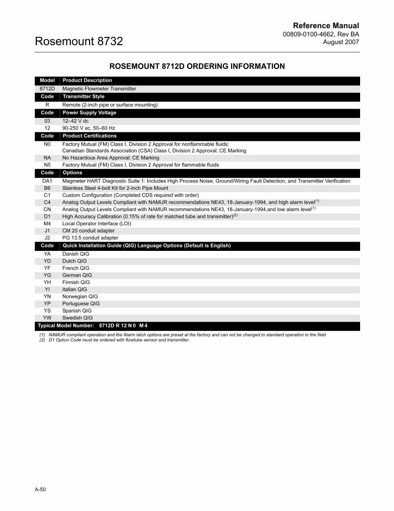
Reference Manual00809-0100-4662, Rev BA
August 2007Rosemount 8732
ROSEMOUNT 8712D ORDERING INFORMATION
Model Product Description
8712D Magnetic Flowmeter Transmitter
Code Transmitter Style
R Remote (2-inch pipe or surface mounting)
Code Power Supply Voltage
03 12–42 V dc
12 90-250 V ac, 50–60 Hz
Code Product Certifications
N0 Factory Mutual (FM) Class I, Division 2 Approval for nonflammable fluids;
Canadian Standards Association (CSA) Class I, Division 2 Approval; CE Marking
NA No Hazardous Area Approval; CE Marking
N5 Factory Mutual (FM) Class I, Division 2 Approval for flammable fluids
Code Options
DA1 Magmeter HART Diagnostic Suite 1: Includes High Process Noise, Ground/Wiring Fault Detection, and Transmitter Verification
B6 Stainless Steel 4-bolt Kit for 2-inch Pipe Mount
C1 Custom Configuration (Completed CDS required with order)
C4 Analog Output Levels Compliant with NAMUR recommendations NE43, 18-January-1994, and high alarm level(1)
(1) NAMUR compliant operation and the Alarm latch options are preset at the factory and can not be changed to standard operation in the field
CN Analog Output Levels Compliant with NAMUR recommendations NE43, 18-January-1994,and low alarm level(1)
D1 High Accuracy Calibration (0.15% of rate for matched tube and transmitter)(2)
(2) D1 Option Code must be ordered with flowtube sensor and transmitter
M4 Local Operator Interface (LOI)
J1 CM 20 conduit adapter
J2 PG 13.5 conduit adapter
Code Quick Installation Guide (QIG) Language Options (Default is English)
YA Danish QIG
YD Dutch QIG
YF French QIG
YG German QIG
YH Finnish QIG
YI Italian QIG
YN Norwegian QIG
YP Portuguese QIG
YS Spanish QIG
YW Swedish QIG
Typical Model Number: 8712D R 12 N 0 M 4
A-50
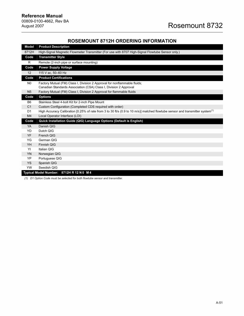
Reference Manual 00809-0100-4662, Rev BA
August 2007 Rosemount 8732
ROSEMOUNT 8712H ORDERING INFORMATIONModel Product Description
8712H High-Signal Magnetic Flowmeter Transmitter (For use with 8707 High-Signal Flowtube Sensor only.)
Code Transmitter Style
R Remote (2-inch pipe or surface mounting)
Code Power Supply Voltage
12 115 V ac, 50–60 Hz
Code Product Certifications
N0 Factory Mutual (FM) Class I, Division 2 Approval for nonflammable fluids;
Canadian Standards Association (CSA) Class I, Division 2 Approval
N5 Factory Mutual (FM) Class I, Division 2 Approval for flammable fluids
Code Options
B6 Stainless Steel 4-bolt Kit for 2-inch Pipe Mount
C1 Custom Configuration (Completed CDS required with order)
D1 High Accuracy Calibration [0.25% of rate from 3 to 30 ft/s (0.9 to 10 m/s)] matched flowtube sensor and transmitter system(1)
(1) D1 Option Code must be selected for both flowtube sensor and transmitter.
M4 Local Operator Interface (LOI)
Code Quick Installation Guide (QIG) Language Options (Default is English)
YA Danish QIG
YD Dutch QIG
YF French QIG
YG German QIG
YH Finnish QIG
YI Italian QIG
YN Norwegian QIG
YP Portuguese QIG
YS Spanish QIG
YW Swedish QIG
Typical Model Number: 8712H R 12 N 0 M 4
A-51
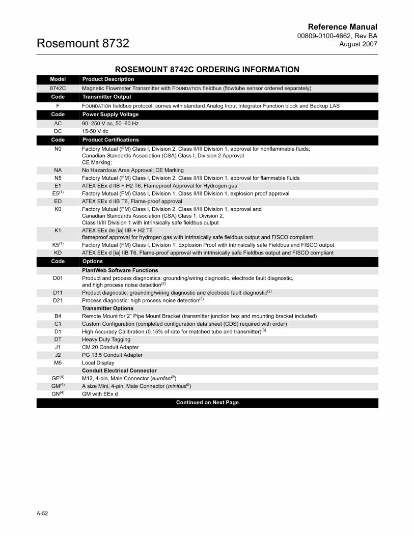
Reference Manual00809-0100-4662, Rev BA
August 2007Rosemount 8732
ROSEMOUNT 8742C ORDERING INFORMATION Model Product Description
8742C Magnetic Flowmeter Transmitter with FOUNDATION fieldbus (flowtube sensor ordered separately)
Code Transmitter Output
F FOUNDATION fieldbus protocol, comes with standard Analog Input Integrator Function block and Backup LAS
Code Power Supply Voltage
AC 90–250 V ac, 50–60 Hz
DC 15-50 V dc
Code Product Certifications
N0 Factory Mutual (FM) Class I, Division 2, Class II/III Division 1, approval for nonflammable fluids;
Canadian Standards Association (CSA) Class I, Division 2 Approval
CE Marking;
NA No Hazardous Area Approval; CE Marking
N5 Factory Mutual (FM) Class I, Division 2, Class II/III Division 1, approval for flammable fluids
E1 ATEX EEx d IIB + H2 T6, Flameproof Approval for Hydrogen gas
E5(1) Factory Mutual (FM) Class I, Division 1, Class II/III Division 1, explosion proof approval
ED ATEX EEx d IIB T6, Flame-proof approval
K0 Factory Mutual (FM) Class I, Division 2, Class II/III Division 1, approval and
Canadian Standards Association (CSA) Class 1, Division 2,
Class II/III Division 1 with intrinsically safe fieldbus output
K1 ATEX EEx de [ia] IIB + H2 T6
flameproof approval for hydrogen gas with intrinsically safe fieldbus output and FISCO compliant
K5(1) Factory Mutual (FM) Class I, Division 1, Explosion Proof with intrinsically safe Fieldbus and FISCO output
KD ATEX EEx d [ia] IIB T6, Flame-proof approval with intrinsically safe Fieldbus output and FISCO compliant
Code Options
PlantWeb Software Functions
D01 Product and process diagnostics: grounding/wiring diagnostic, electrode fault diagnostic,
and high process noise detection(2)
D11 Product diagnostic: grounding/wiring diagnostic and electrode fault diagnostic(2)
D21 Process diagnostic: high process noise detection(2)
Transmitter Options
B4 Remote Mount for 2” Pipe Mount Bracket (transmitter junction box and mounting bracket included)
C1 Custom Configuration (completed configuration data sheet (CDS) required with order)
D1 High Accuracy Calibration (0.15% of rate for matched tube and transmitter)(3)
DT Heavy Duty Tagging
J1 CM 20 Conduit Adapter
J2 PG 13.5 Conduit Adapter
M5 Local Display
Conduit Electrical Connector
GE(4) M12, 4-pin, Male Connector (eurofast®)
GM(4) A size Mini, 4-pin, Male Connector (minifast®)
GN(4) GM with EEx d
Continued on Next Page
A-52
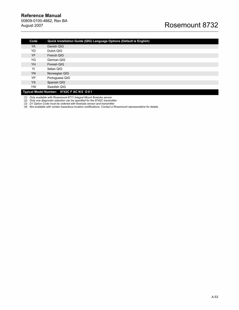
Reference Manual 00809-0100-4662, Rev BA
August 2007 Rosemount 8732
Code Quick Installation Guide (QIG) Language Options (Default is English)
YA Danish QIG
YD Dutch QIG
YF French QIG
YG German QIG
YH Finnish QIG
YI Italian QIG
YN Norwegian QIG
YP Portuguese QIG
YS Spanish QIG
YW Swedish QIG
Typical Model Number: 8742C F AC N 0 D 0 1
(1) Only available with Rosemount 8711 Integral Mount flowtube sensor(2) Only one diagnostic selection can be specified for the 8742C transmitter.(3) D1 Option Code must be ordered with flowtube sensor and transmitter(4) Not available with certain hazardous location certifications. Contact a Rosemount representative for details
A-53

Reference Manual00809-0100-4662, Rev BA
August 2007Rosemount 8732
ROSEMOUNT 8705 ORDERING INFORMATIONCode Product Description Availability
8705 Magnetic Flowmeter Flowtube Sensor •
Code Lining Material
A PFA •
T Teflon (PTFE) •
F Tefzel (ETFE) •
P Polyurethane •
N Neoprene •
L Linatex •
Code Electrode Material
S 316L Stainless Steel •
H Hastelloy C-276 •
T Tantalum •
P Plantinum Iridium •
N Titanium •
Electrode Material (From Above)
Code Electrode Type Code S Code H Code T Code P Code N
A 2 Electrodes - Standard • • • • •
B 2 Electrodes - Bullet Nose • •
E 3rd Grounding Electrode • • • • •
Lining Material (From Above)
Code Line Size Code A Code T Code F Code P
Code
N and L
005 1/2 in • • • NA NA
010 1 in • • • • •
015 1 1/2 in • • • • •
020 2 in. • • • • •
030 3 in. • • • • •
040 4 in. • • • • •
060 6 in. • • • • •
080 8 in. • • • • •
100 10 in. • • • • •
120 12 in. • • • • •
140 14 in NA • • • •
160 16 in. NA • • • •
180 18 in NA • NA • •
200 20 in NA • NA • •
240 24 in NA • NA • •
300 30 in NA • NA • •
360 36 in NA • NA • •
Continued on Next Page
A-54
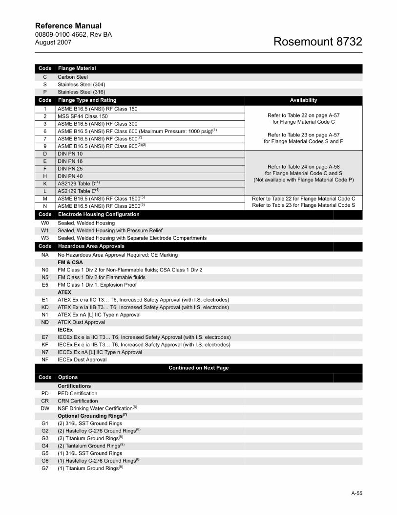
Reference Manual 00809-0100-4662, Rev BA
August 2007 Rosemount 8732
Code Flange Material
C Carbon Steel
S Stainless Steel (304)
P Stainless Steel (316)
Code Flange Type and Rating Availability
1 ASME B16.5 (ANSI) RF Class 150
Refer to Table 22 on page A-57
for Flange Material Code C
Refer to Table 23 on page A-57
for Flange Material Codes S and P
2 MSS SP44 Class 150
3 ASME B16.5 (ANSI) RF Class 300
6 ASME B16.5 (ANSI) RF Class 600 (Maximum Pressure: 1000 psig)(1)
7 ASME B16.5 (ANSI) RF Class 600(2)
9 ASME B16.5 (ANSI) RF Class 900(2)(3)
D DIN PN 10
Refer to Table 24 on page A-58
for Flange Material Code C and S
(Not available with Flange Material Code P)
E DIN PN 16
F DIN PN 25
H DIN PN 40
K AS2129 Table D(4)
L AS2129 Table E(4)
M ASME B16.5 (ANSI) RF Class 1500(5) Refer to Table 22 for Flange Material Code C
Refer to Table 23 for Flange Material Code SN ASME B16.5 (ANSI) RF Class 2500(5)
Code Electrode Housing Configuration
W0 Sealed, Welded Housing
W1 Sealed, Welded Housing with Pressure Relief
W3 Sealed, Welded Housing with Separate Electrode Compartments
Code Hazardous Area Approvals
NA No Hazardous Area Approval Required; CE Marking
FM & CSA
N0 FM Class 1 Div 2 for Non-Flammable fluids; CSA Class 1 Div 2
N5 FM Class 1 Div 2 for Flammable fluids
E5 FM Class 1 Div 1, Explosion Proof
ATEX
E1 ATEX Ex e ia IIC T3… T6, Increased Safety Approval (with I.S. electrodes)
KD ATEX Ex e ia IIB T3… T6, Increased Safety Approval (with I.S. electrodes)
N1 ATEX Ex nA [L] IIC Type n Approval
ND ATEX Dust Approval
IECEx
E7 IECEx Ex e ia IIC T3… T6, Increased Safety Approval (with I.S. electrodes)
KF IECEx Ex e ia IIB T3… T6, Increased Safety Approval (with I.S. electrodes)
N7 IECEx Ex nA [L] IIC Type n Approval
NF IECEx Dust Approval
Continued on Next Page
Code Options
Certifications
PD PED Certification
CR CRN Certification
DW NSF Drinking Water Certification(6)
Optional Grounding Rings(7)
G1 (2) 316L SST Ground Rings
G2 (2) Hastelloy C-276 Ground Rings(8)
G3 (2) Titanium Ground Rings(8)
G4 (2) Tantalum Ground Rings(9)
G5 (1) 316L SST Ground Rings
G6 (1) Hastelloy C-276 Ground Rings(8)
G7 (1) Titanium Ground Rings(8)
A-55
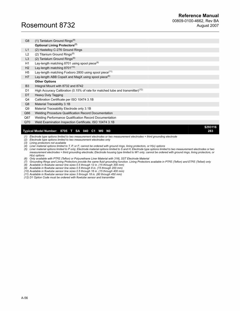
Reference Manual00809-0100-4662, Rev BA
August 2007Rosemount 8732
G8 (1) Tantalum Ground Rings(9)
Optional Lining Protectors(7)
L1 (2) Hastelloy C-276 Ground Rings
L2 (2) Titanium Ground Rings(8)
L3 (2) Tantalum Ground Rings(8)
H1 Lay-length matching 8701 using spool piece(8)
H2 Lay-length matching 8701(10)
H5 Lay-length matching Foxboro 2800 using spool piece(11)
H7 Lay-length ABB CopaX and MagX using spool piece(8)
Other Options
B3 Integral Mount with 8732 and 8742
D1 High Accuracy Calibration (0.15% of rate for matched tube and transmitter)(12)
DT Heavy Duty Tagging
Q4 Calibration Certificate per ISO 10474 3.1B
Q8 Material Traceability 3.1B
Q9 Material Traceability Electrode only 3.1B
Q66 Welding Procedure Qualification Record Documentation
Q67 Welding Performance Qualification Record Documentation
Q70 Weld Examination Inspection Certificate, ISO 10474 3.1B
Typical Model Number: 8705 T SA 040 C1 W0 N0
$293116
283
(1) Electrode type options limited to two measurement electrodes or two measurement electrodes + third grounding electrode(2) Electrode type options limited to two measurement electrodes only(3) Lining protectors not available(4) Liner material options limited to T, P, or F; cannot be ordered with ground rings, lining protectors, or H(x) options(5) Liner material options limited to P only; Electrode material options limited to S and H; Electrode type options limited to two measurement electrodes or two
measurement electrodes + third grounding electrode; Electrode housing type limited to W1 only; cannot be ordered with ground rings, lining protectors, or H(x) options
(6) Only available with PTFE (Teflon) or Polyurethane Liner Material with 316L SST Electrode Material(7) Grounding Rings and Lining Protectors provide the same fluid grounding function. Lining Protectors available in PTFE (Teflon) and ETFE (Tefzel) only(8) Available in flowtube sensor line sizes 0.5 through 12 in. (15 through 300 mm) (9) Available in flowtube sensor line sizes 0.5 through 8 in. (15 through 200 mm) (10) Available in flowtube sensor line sizes 0.5 through 16 in. (15 through 400 mm)(11) Available in flowtube sensor line sizes 3 through 18 in. (80 through 450 mm)(12) D1 Option Code must be ordered with flowtube sensor and transmitter
A-56
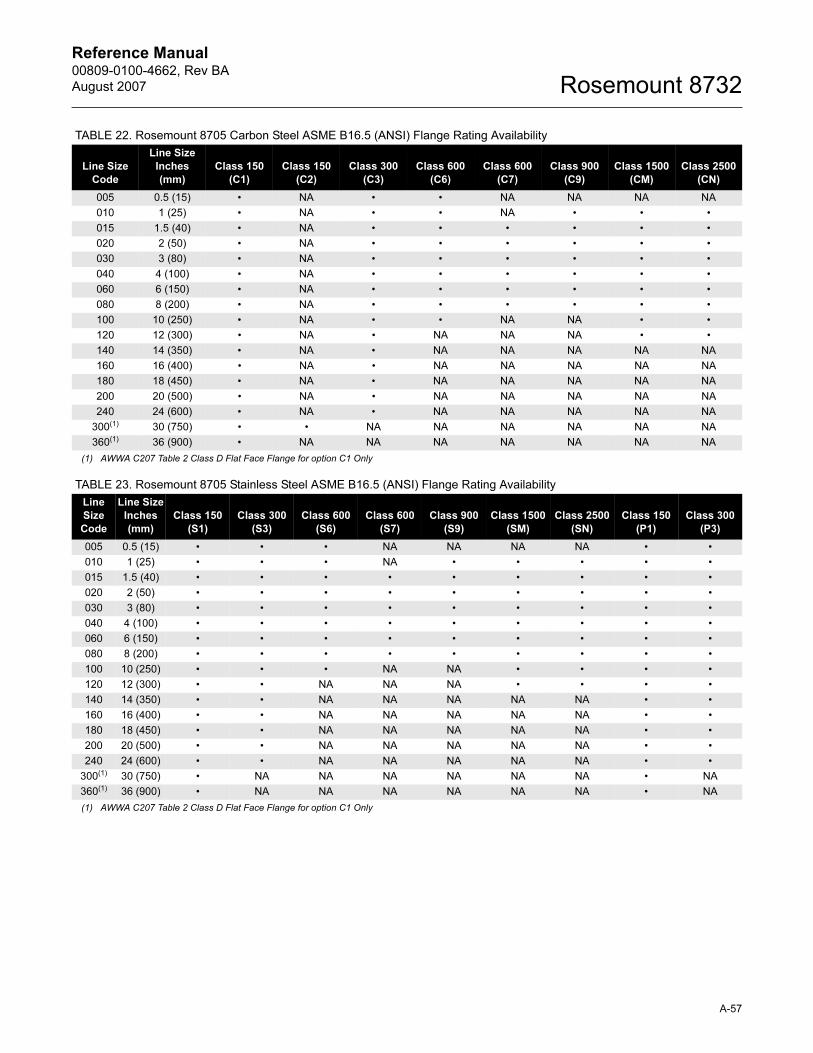
Reference Manual 00809-0100-4662, Rev BA
August 2007 Rosemount 8732
TABLE 22. Rosemount 8705 Carbon Steel ASME B16.5 (ANSI) Flange Rating Availability
TABLE 23. Rosemount 8705 Stainless Steel ASME B16.5 (ANSI) Flange Rating Availability
Line Size
Code
Line Size
Inches
(mm)
Class 150
(C1)
Class 150
(C2)
Class 300
(C3)
Class 600
(C6)
Class 600
(C7)
Class 900
(C9)
Class 1500
(CM)
Class 2500
(CN)
005 0.5 (15) • NA • • NA NA NA NA
010 1 (25) • NA • • NA • • •
015 1.5 (40) • NA • • • • • •
020 2 (50) • NA • • • • • •
030 3 (80) • NA • • • • • •
040 4 (100) • NA • • • • • •
060 6 (150) • NA • • • • • •
080 8 (200) • NA • • • • • •
100 10 (250) • NA • • NA NA • •
120 12 (300) • NA • NA NA NA • •
140 14 (350) • NA • NA NA NA NA NA
160 16 (400) • NA • NA NA NA NA NA
180 18 (450) • NA • NA NA NA NA NA
200 20 (500) • NA • NA NA NA NA NA
240 24 (600) • NA • NA NA NA NA NA
300(1)
(1) AWWA C207 Table 2 Class D Flat Face Flange for option C1 Only
30 (750) • • NA NA NA NA NA NA
360(1) 36 (900) • NA NA NA NA NA NA NA
Line
Size
Code
Line Size
Inches
(mm)
Class 150
(S1)
Class 300
(S3)
Class 600
(S6)
Class 600
(S7)
Class 900
(S9)
Class 1500
(SM)
Class 2500
(SN)
Class 150
(P1)
Class 300
(P3)
005 0.5 (15) • • • NA NA NA NA • •
010 1 (25) • • • NA • • • • •
015 1.5 (40) • • • • • • • • •
020 2 (50) • • • • • • • • •
030 3 (80) • • • • • • • • •
040 4 (100) • • • • • • • • •
060 6 (150) • • • • • • • • •
080 8 (200) • • • • • • • • •
100 10 (250) • • • NA NA • • • •
120 12 (300) • • NA NA NA • • • •
140 14 (350) • • NA NA NA NA NA • •
160 16 (400) • • NA NA NA NA NA • •
180 18 (450) • • NA NA NA NA NA • •
200 20 (500) • • NA NA NA NA NA • •
240 24 (600) • • NA NA NA NA NA • •
300(1)
(1) AWWA C207 Table 2 Class D Flat Face Flange for option C1 Only
30 (750) • NA NA NA NA NA NA • NA
360(1) 36 (900) • NA NA NA NA NA NA • NA
A-57
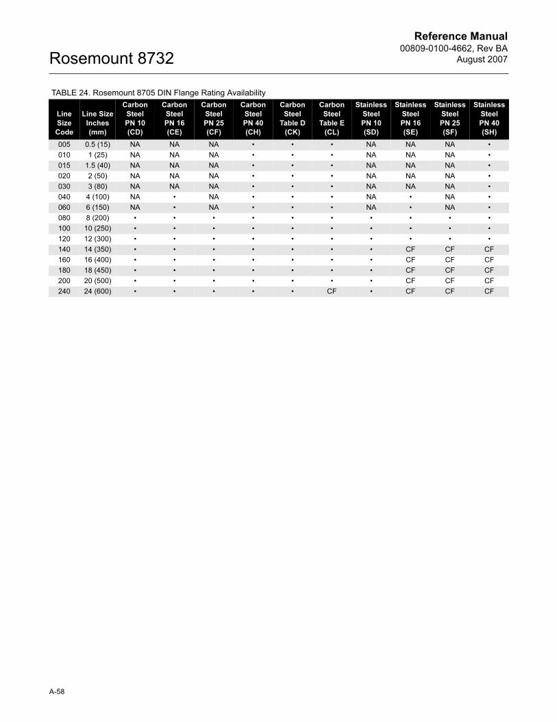
Reference Manual00809-0100-4662, Rev BA
August 2007Rosemount 8732
TABLE 24. Rosemount 8705 DIN Flange Rating Availability
Line
Size
Code
Line Size
Inches
(mm)
Carbon
Steel
PN 10
(CD)
Carbon
Steel
PN 16
(CE)
Carbon
Steel
PN 25
(CF)
Carbon
Steel
PN 40
(CH)
Carbon
Steel
Table D
(CK)
Carbon
Steel
Table E
(CL)
Stainless
Steel
PN 10
(SD)
Stainless
Steel
PN 16
(SE)
Stainless
Steel
PN 25
(SF)
Stainless
Steel
PN 40
(SH)
005 0.5 (15) NA NA NA • • • NA NA NA •
010 1 (25) NA NA NA • • • NA NA NA •
015 1.5 (40) NA NA NA • • • NA NA NA •
020 2 (50) NA NA NA • • • NA NA NA •
030 3 (80) NA NA NA • • • NA NA NA •
040 4 (100) NA • NA • • • NA • NA •
060 6 (150) NA • NA • • • NA • NA •
080 8 (200) • • • • • • • • • •
100 10 (250) • • • • • • • • • •
120 12 (300) • • • • • • • • • •
140 14 (350) • • • • • • • CF CF CF
160 16 (400) • • • • • • • CF CF CF
180 18 (450) • • • • • • • CF CF CF
200 20 (500) • • • • • • • CF CF CF
240 24 (600) • • • • • CF • CF CF CF
A-58
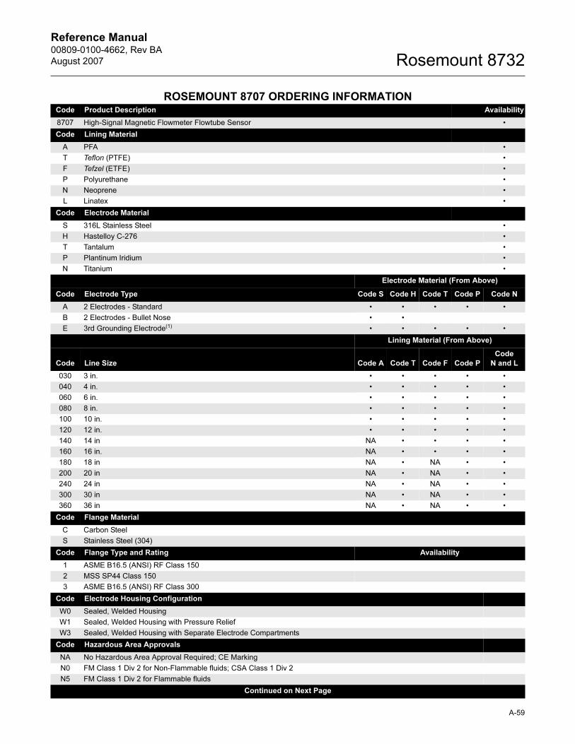
Reference Manual 00809-0100-4662, Rev BA
August 2007 Rosemount 8732
A-59
ROSEMOUNT 8707 ORDERING INFORMATIONCode Product Description Availability
8707 High-Signal Magnetic Flowmeter Flowtube Sensor •
Code Lining Material
A PFA •
T Teflon (PTFE) •
F Tefzel (ETFE) •
P Polyurethane •
N Neoprene •
L Linatex •
Code Electrode Material
S 316L Stainless Steel •
H Hastelloy C-276 •
T Tantalum •
P Plantinum Iridium •
N Titanium •
Electrode Material (From Above)
Code Electrode Type Code S Code H Code T Code P Code N
A 2 Electrodes - Standard • • • • •
B 2 Electrodes - Bullet Nose • •
E 3rd Grounding Electrode(1) • • • • •
Lining Material (From Above)
Code Line Size Code A Code T Code F Code P
Code
N and L
030 3 in. • • • • •
040 4 in. • • • • •
060 6 in. • • • • •
080 8 in. • • • • •
100 10 in. • • • • •
120 12 in. • • • • •
140 14 in NA • • • •
160 16 in. NA • • • •
180 18 in NA • NA • •
200 20 in NA • NA • •
240 24 in NA • NA • •
300 30 in NA • NA • •
360 36 in NA • NA • •
Code Flange Material
C Carbon Steel
S Stainless Steel (304)
Code Flange Type and Rating Availability
1 ASME B16.5 (ANSI) RF Class 150
2 MSS SP44 Class 150
3 ASME B16.5 (ANSI) RF Class 300
Code Electrode Housing Configuration
W0 Sealed, Welded Housing
W1 Sealed, Welded Housing with Pressure Relief
W3 Sealed, Welded Housing with Separate Electrode Compartments
Code Hazardous Area Approvals
NA No Hazardous Area Approval Required; CE Marking
N0 FM Class 1 Div 2 for Non-Flammable fluids; CSA Class 1 Div 2
N5 FM Class 1 Div 2 for Flammable fluids
Continued on Next Page
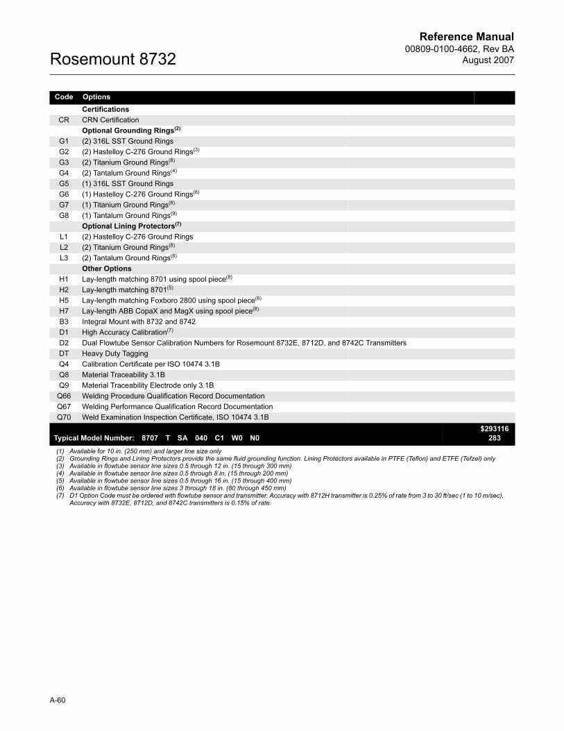
Reference Manual00809-0100-4662, Rev BA
August 2007Rosemount 8732
Code Options
Certifications
CR CRN Certification
Optional Grounding Rings(2)
G1 (2) 316L SST Ground Rings
G2 (2) Hastelloy C-276 Ground Rings(3)
G3 (2) Titanium Ground Rings(8)
G4 (2) Tantalum Ground Rings(4)
G5 (1) 316L SST Ground Rings
G6 (1) Hastelloy C-276 Ground Rings(8)
G7 (1) Titanium Ground Rings(8)
G8 (1) Tantalum Ground Rings(9)
Optional Lining Protectors(7)
L1 (2) Hastelloy C-276 Ground Rings
L2 (2) Titanium Ground Rings(8)
L3 (2) Tantalum Ground Rings(8)
Other Options
H1 Lay-length matching 8701 using spool piece(8)
H2 Lay-length matching 8701(5)
H5 Lay-length matching Foxboro 2800 using spool piece(6)
H7 Lay-length ABB CopaX and MagX using spool piece(8)
B3 Integral Mount with 8732 and 8742
D1 High Accuracy Calibration(7)
D2 Dual Flowtube Sensor Calibration Numbers for Rosemount 8732E, 8712D, and 8742C Transmitters
DT Heavy Duty Tagging
Q4 Calibration Certificate per ISO 10474 3.1B
Q8 Material Traceability 3.1B
Q9 Material Traceability Electrode only 3.1B
Q66 Welding Procedure Qualification Record Documentation
Q67 Welding Performance Qualification Record Documentation
Q70 Weld Examination Inspection Certificate, ISO 10474 3.1B
Typical Model Number: 8707 T SA 040 C1 W0 N0
$293116
283
(1) Available for 10 in. (250 mm) and larger line size only(2) Grounding Rings and Lining Protectors provide the same fluid grounding function. Lining Protectors available in PTFE (Teflon) and ETFE (Tefzel) only(3) Available in flowtube sensor line sizes 0.5 through 12 in. (15 through 300 mm) (4) Available in flowtube sensor line sizes 0.5 through 8 in. (15 through 200 mm) (5) Available in flowtube sensor line sizes 0.5 through 16 in. (15 through 400 mm)(6) Available in flowtube sensor line sizes 3 through 18 in. (80 through 450 mm)(7) D1 Option Code must be ordered with flowtube sensor and transmitter. Accuracy with 8712H transmitter is 0.25% of rate from 3 to 30 ft/sec (1 to 10 m/sec).
Accuracy with 8732E, 8712D, and 8742C transmitters is 0.15% of rate.
A-60
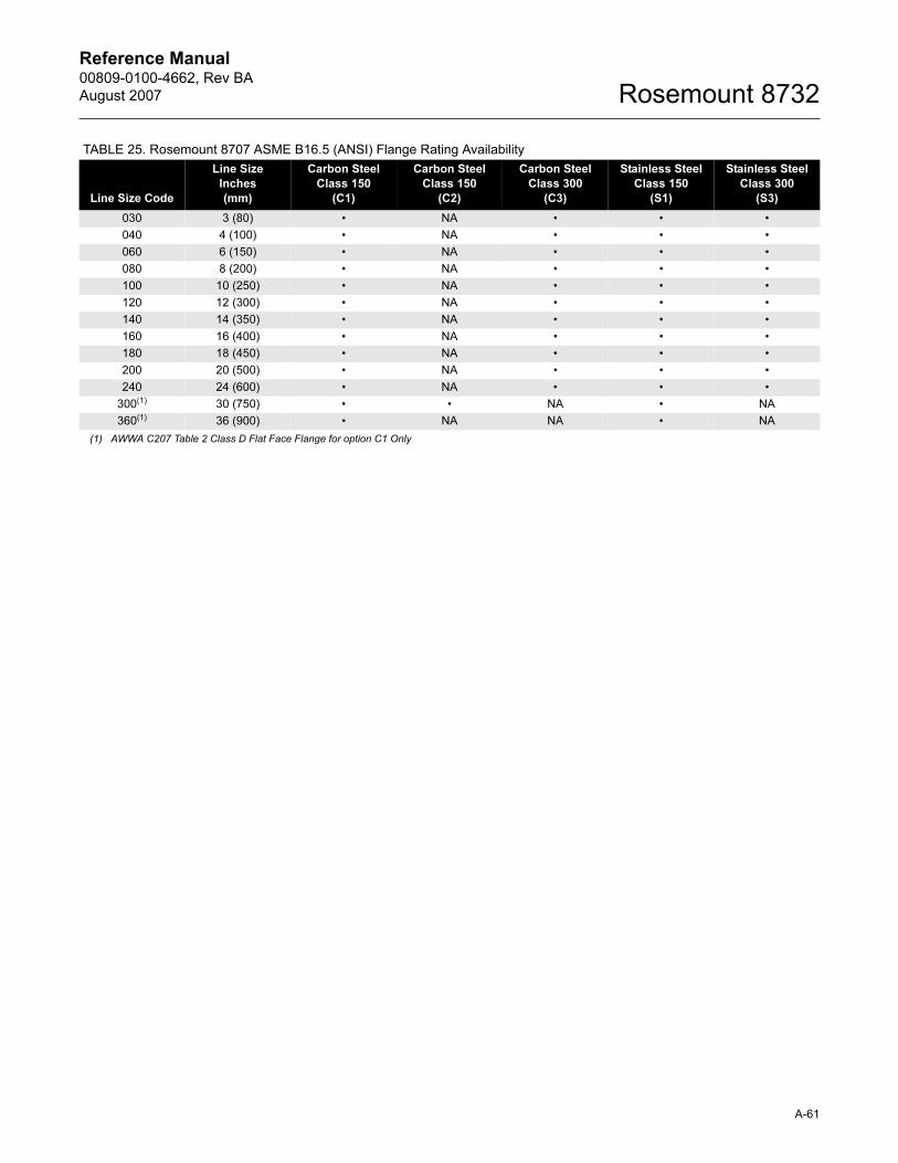
Reference Manual 00809-0100-4662, Rev BA
August 2007 Rosemount 8732
TABLE 25. Rosemount 8707 ASME B16.5 (ANSI) Flange Rating Availability
Line Size Code
Line Size
Inches
(mm)
Carbon Steel
Class 150
(C1)
Carbon Steel
Class 150
(C2)
Carbon Steel
Class 300
(C3)
Stainless Steel
Class 150
(S1)
Stainless Steel
Class 300
(S3)
030 3 (80) • NA • • •
040 4 (100) • NA • • •
060 6 (150) • NA • • •
080 8 (200) • NA • • •
100 10 (250) • NA • • •
120 12 (300) • NA • • •
140 14 (350) • NA • • •
160 16 (400) • NA • • •
180 18 (450) • NA • • •
200 20 (500) • NA • • •
240 24 (600) • NA • • •
300(1)
(1) AWWA C207 Table 2 Class D Flat Face Flange for option C1 Only
30 (750) • • NA • NA
360(1) 36 (900) • NA NA • NA
A-61
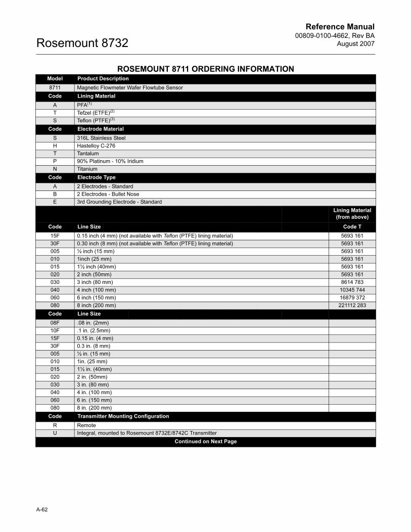
Reference Manual00809-0100-4662, Rev BA
August 2007Rosemount 8732
ROSEMOUNT 8711 ORDERING INFORMATIONModel Product Description
8711 Magnetic Flowmeter Wafer Flowtube Sensor
Code Lining Material
A PFA(1)
T Tefzel (ETFE)(2)
S Teflon (PTFE)(3)
Code Electrode Material
S 316L Stainless Steel
H Hastelloy C-276
T Tantalum
P 90% Platinum - 10% Iridium
N Titanium
Code Electrode Type
A 2 Electrodes - Standard
B 2 Electrodes - Bullet Nose
E 3rd Grounding Electrode - Standard
Lining Material
(from above)
Code Line Size Code T
15F 0.15 inch (4 mm) (not available with Teflon (PTFE) lining material) 5693 161
30F 0.30 inch (8 mm) (not available with Teflon (PTFE) lining material) 5693 161
005 ½ inch (15 mm) 5693 161
010 1inch (25 mm) 5693 161
015 1½ inch (40mm) 5693 161
020 2 inch (50mm) 5693 161
030 3 inch (80 mm) 8614 783
040 4 inch (100 mm) 10345 744
060 6 inch (150 mm) 16879 372
080 8 inch (200 mm) 221112 283
Code Line Size
08F .08 in. (2mm)
10F .1 in. (2.5mm)
15F 0.15 in. (4 mm)
30F 0.3 in. (8 mm)
005 ½ in. (15 mm)
010 1in. (25 mm)
015 1½ in. (40mm)
020 2 in. (50mm)
030 3 in. (80 mm)
040 4 in. (100 mm)
060 6 in. (150 mm)
080 8 in. (200 mm)
Code Transmitter Mounting Configuration
R Remote
U Integral, mounted to Rosemount 8732E/8742C Transmitter
Continued on Next Page
A-62
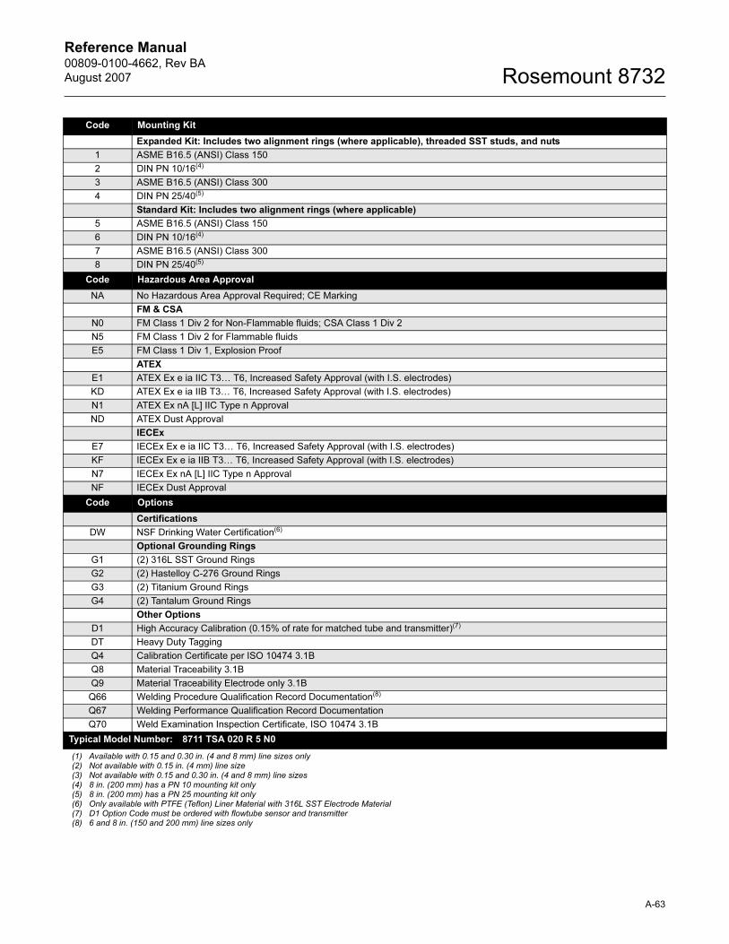
Reference Manual 00809-0100-4662, Rev BA
August 2007 Rosemount 8732
Code Mounting Kit
Expanded Kit: Includes two alignment rings (where applicable), threaded SST studs, and nuts
1 ASME B16.5 (ANSI) Class 150
2 DIN PN 10/16(4)
3 ASME B16.5 (ANSI) Class 300
4 DIN PN 25/40(5)
Standard Kit: Includes two alignment rings (where applicable)
5 ASME B16.5 (ANSI) Class 150
6 DIN PN 10/16(4)
7 ASME B16.5 (ANSI) Class 300
8 DIN PN 25/40(5)
Code Hazardous Area Approval
NA No Hazardous Area Approval Required; CE Marking
FM & CSA
N0 FM Class 1 Div 2 for Non-Flammable fluids; CSA Class 1 Div 2
N5 FM Class 1 Div 2 for Flammable fluids
E5 FM Class 1 Div 1, Explosion Proof
ATEX
E1 ATEX Ex e ia IIC T3… T6, Increased Safety Approval (with I.S. electrodes)
KD ATEX Ex e ia IIB T3… T6, Increased Safety Approval (with I.S. electrodes)
N1 ATEX Ex nA [L] IIC Type n Approval
ND ATEX Dust Approval
IECEx
E7 IECEx Ex e ia IIC T3… T6, Increased Safety Approval (with I.S. electrodes)
KF IECEx Ex e ia IIB T3… T6, Increased Safety Approval (with I.S. electrodes)
N7 IECEx Ex nA [L] IIC Type n Approval
NF IECEx Dust Approval
Code Options
Certifications
DW NSF Drinking Water Certification(6)
Optional Grounding Rings
G1 (2) 316L SST Ground Rings
G2 (2) Hastelloy C-276 Ground Rings
G3 (2) Titanium Ground Rings
G4 (2) Tantalum Ground Rings
Other Options
D1 High Accuracy Calibration (0.15% of rate for matched tube and transmitter)(7)
DT Heavy Duty Tagging
Q4 Calibration Certificate per ISO 10474 3.1B
Q8 Material Traceability 3.1B
Q9 Material Traceability Electrode only 3.1B
Q66 Welding Procedure Qualification Record Documentation(8)
Q67 Welding Performance Qualification Record Documentation
Q70 Weld Examination Inspection Certificate, ISO 10474 3.1B
Typical Model Number: 8711 TSA 020 R 5 N0
(1) Available with 0.15 and 0.30 in. (4 and 8 mm) line sizes only(2) Not available with 0.15 in. (4 mm) line size(3) Not available with 0.15 and 0.30 in. (4 and 8 mm) line sizes(4) 8 in. (200 mm) has a PN 10 mounting kit only(5) 8 in. (200 mm) has a PN 25 mounting kit only(6) Only available with PTFE (Teflon) Liner Material with 316L SST Electrode Material(7) D1 Option Code must be ordered with flowtube sensor and transmitter(8) 6 and 8 in. (150 and 200 mm) line sizes only
A-63
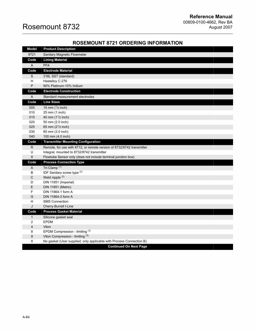
Reference Manual00809-0100-4662, Rev BA
August 2007Rosemount 8732
ROSEMOUNT 8721 ORDERING INFORMATIONModel Product Description
8721 Sanitary Magnetic Flowmeter
Code Lining Material
A PFA
Code Electrode Material
S 316L SST (standard)
H Hastelloy C-276
P 90% Platinum-10% Iridium
Code Electrode Construction
A Standard measurement electrodes
Code Line Sizes
005 15 mm (1/2 inch)
010 25 mm (1 inch)
015 40 mm (11/2 inch)
020 50 mm (2.0 inch)
025 65 mm (21/2 inch)
030 80 mm (3.0 inch)
040 100 mm (4.0 inch)
Code Transmitter Mounting Configuration
R Remote, for use with 8712, or remote version of 8732/8742 transmitter
U Integral, mounted to 8732/8742 transmitter
X Flowtube Sensor only (does not include terminal junction box)
Code Process Connection Type
A Tri-Clamp (1)
B IDF Sanitary screw type (2)
C Weld nipple (2)
D DIN 11851 (Imperial)
E DIN 11851 (Metric)
F DIN 11864-1 form A
G DIN 11864-2 form A
H SMS Connection
J Cherry-Burrell I-Line
Code Process Gasket Material
1 Silicone gasket seal
2 EPDM
4 Viton
8 EPDM Compression - limiting (3)
9 Viton Compression - limiting (3)
X No gasket (User supplied; only applicable with Process Connection B)
Continued On Next Page
A-64
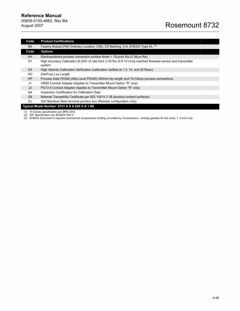
Reference Manual 00809-0100-4662, Rev BA
August 2007 Rosemount 8732
Code Product Certifications
N0 Factory Mutual (FM) Ordinary Location; CSA; CE Marking; 3-A; EHEDG Type EL (3)
Code Options
AH Electropolished process connection surface finish < 15μinch Ra (0.38μm Ra)
D1 High Accuracy Calibration [0.25% of rate from 3-30 ft/s (0.9-10 m/s)] matched flowtube sensor and transmitter
system
D3 High Velocity Calibration Verification (calibration verified at 1.3, 10, and 20 ft/sec)
HD DanFoss Lay Length
HP Process Data PD340 (Alfa-Laval PD340) 250mm lay length and Tri-Clamp process connections
J1 CM20 Conduit Adapter (Applies to Transmitter Mount Option “R” only)
J2 PG13.5 Conduit Adapter (Applies to Transmitter Mount Option “R” only)
Q4 Inspection Certification for Calibration Data
Q8 Material Traceability Certificate per ISO 10474 3.1B (product contact surfaces)
SJ 304 Stainless Steel terminal junction box (Remote configuration only)
Typical Model Number: 8721 A S A 020 U A 1 N0
(1) Tri-Clamp specification per BPE-2002(2) IDF Specification per BS4825 Part 4(3) EHEDG Document 8 requires mechanical compression limiting, provided by Compression - limiting gaskets for line sizes 1- 4 inch only.
A-65

Reference Manual00809-0100-4662, Rev BA
August 2007Rosemount 8732
ROSEMOUNT 8714D ORDERING INFORMATION
Model Description
8714DQ4 Reference Calibration Standard
A-66
Reference Manual 00809-0100-4662, Rev BA
August 2007 Rosemount 8732
Tagging The flowtube sensor and transmitter will be tagged, at no charge, in
accordance with customer requirements.
Transmitter tag character height is
0.125 in. (3.18 mm).
Flowtube Sensor tag: 40 character maximum.
Transmitter tag: see Configuration Data Sheet for character maximum.
Ordering Procedure
To order, select the desired flowtube sensor and/or transmitter by specifying
model codes from the ordering table.
For remote transmitter applications, note the cable specification
requirements.
Flowtube Sensors and transmitters must be selected from Product Data
Sheet 00813-0100-4727.
Standard Configuration
Unless the Configuration Data Sheet is completed, the transmitter will be
shipped as follows:
The Rosemount 8732E and the 8742C Transmitter are factory-calibrated with
the attached flowtube sensor size and appropriate calibration number.
Engineering Units: ft/sec
4 mA (1 V dc): 0
20 mA (5 V dc): 30
Tube Size: 3-inch
Empty Pipe: Off
Flowtube Sensor Calibration
Number:
1000005010000000
A-67
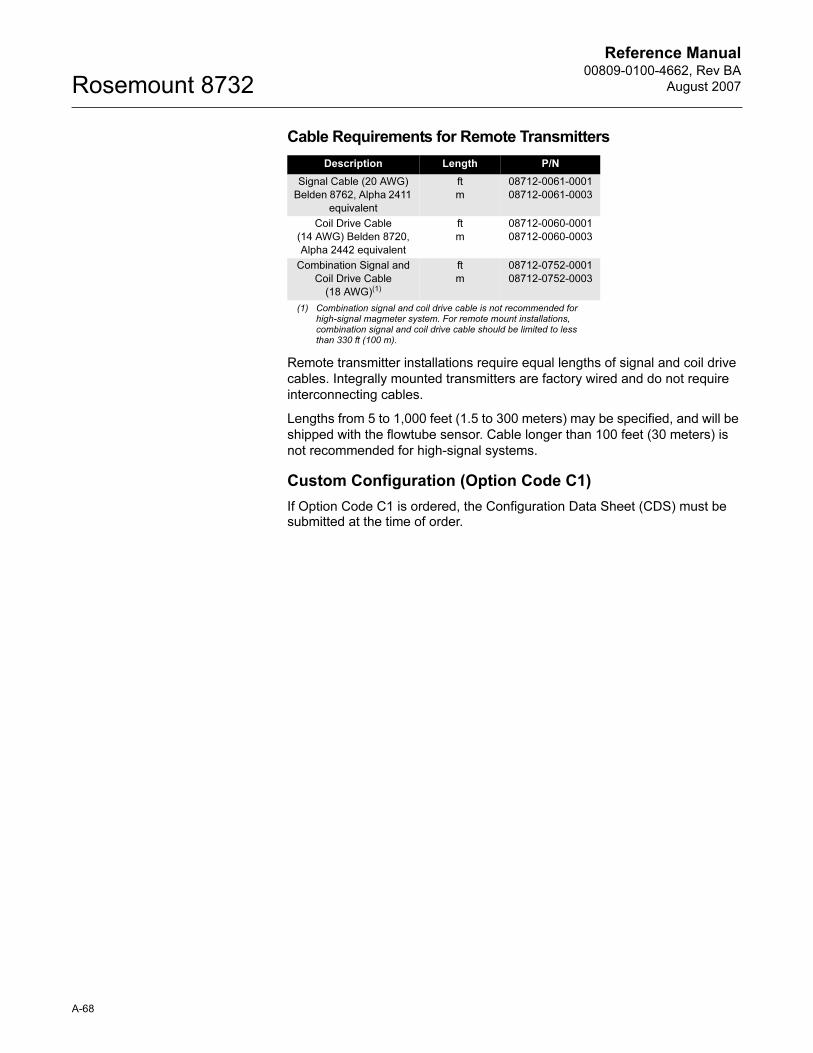
Reference Manual00809-0100-4662, Rev BA
August 2007Rosemount 8732
Cable Requirements for Remote Transmitters
Remote transmitter installations require equal lengths of signal and coil drive
cables. Integrally mounted transmitters are factory wired and do not require
interconnecting cables.
Lengths from 5 to 1,000 feet (1.5 to 300 meters) may be specified, and will be
shipped with the flowtube sensor. Cable longer than 100 feet (30 meters) is
not recommended for high-signal systems.
Custom Configuration (Option Code C1)
If Option Code C1 is ordered, the Configuration Data Sheet (CDS) must be submitted at the time of order.
Description Length P/N
Signal Cable (20 AWG)
Belden 8762, Alpha 2411
equivalent
ft
m
08712-0061-0001
08712-0061-0003
Coil Drive Cable
(14 AWG) Belden 8720,
Alpha 2442 equivalent
ft
m
08712-0060-0001
08712-0060-0003
Combination Signal and
Coil Drive Cable
(18 AWG)(1)
(1) Combination signal and coil drive cable is not recommended for high-signal magmeter system. For remote mount installations, combination signal and coil drive cable should be limited to less than 330 ft (100 m).
ft
m
08712-0752-0001
08712-0752-0003
A-68
Reference Manual 00809-0100-4662, Rev BA
August 2007 Rosemount 8732
Appendix B Approval Information
European Directive Information . . . . . . . . . . . . . . . . . . . . page B-1
Hazardous Locations Product Approvals Offering . . . . . page B-2
Hazardous Location Certifications . . . . . . . . . . . . . . . . . . page B-7
Approved Manufacturing Locations
Rosemount Inc. — Eden Prairie, Minnesota, USA
Fisher-Rosemount Technologias de Flujo, S.A. de C.V. —Chihuahua MexicoEde, The Netherlands
EUROPEAN DIRECTIVE INFORMATION
The EC declaration of conformity for all applicable European directives for this product can be found on our website at www.rosemount.com. A hard copy may be obtained by contacting our local sales office.
ATEX Directive Rosemount Inc. complies with the ATEX Directive.
Type n protection type in accordance with EN50 021
• Closing of entries in the device must be carried out using the appropriate EExe or EExn metal cable gland and metal blanking plug or any appropriate ATEX approved cable gland and blanking plug with IP66 rating certified by an EU approved certification body.
Flameproof protection type in accordance with EN 60079-0:2004, EN 60079-7: 2007 and IEC 60079-1: 2007
Intrinsic safety protection type in accordance with EN60079-11:2006
European Pressure Equipment Directive (PED) (97/23/EC)
Rosemount 8705 and 8707 Magnetic Flowmeter flowtube sensors in line size and flange combinations:
Line Size: 1 1/2 inch - 3 inch with all flanges available.
Line Size: 4 inch - 24 inch with all DIN flanges and ANSI 150 and ANSI 300 flanges.
Line Size: 30 inch - 36 inch with AWWA 125 flanges QS Certificate of Assessment - EC No. PED-H-20 Module H Conformity Assessment
Rosemount 8711 Magnetic Flowmeter Flowtube Sensors Line Sizes: 1.5, 2, 3, 4, 6, and 8 inch
QS Certificate of Assessment - EC No. PED-H-20Module H Conformity Assessment
www.rosemount.com
Reference Manual00809-0100-4662, Rev BA
August 2007Rosemount 8732
Rosemount 8721 Sanitary Magmeter Flowtube Sensors in line sizes of 11/2 inch and larger:
Module A Conformity Assessment
All other Rosemount 8705/8707/8711/8721 Flowtube Sensors — in line sizes of 1 inch and less: Sound Engineering Practice
Flowtube Sensors that are SEP are outside the scope of PED and cannot be marked for compliance with PED.
Mandatory CE-marking for flowtube sensors in accordance with Article 15 of the PED can be found on the flowtube sensor body (CE 0575).
Flowtube Sensor category I is assessed for conformity per module A procedures.
Flowtube Sensor categories II – IV, use module H for conformity assessment procedures.
Electro Magnetic Compatibility (EMC) (89/336/EEC) (obsolete)
All Models EN 50081-1: 1992, EN 50082-2: 1995 (obsolete),EN 61326: 1997/ A1:1998 / A2:2000
Installed signal wiring should not be run together and should not be in the same cable tray as AC power wiring.
Device must be properly grounded or earthed according to local electric codes.
To improve protection against signal interference, shielded cable is recommended.
Low Voltage Directive (93/68/EEC)
All Models 8732, Model 8742C - AC EN 61010-1: 1995
Other important guidelines
Only use new, original parts.
To prevent the process medium escaping, do not unscrew or remove process flange bolts, adapter bolts or bleed screws during operation.
Maintenance shall only be done by qualified personnel.
CE Marking Compliance with all applicable European Union Directives. (Note: CE Marking is not available on Rosemount 8712H).
HAZARDOUS LOCATIONS PRODUCT APPROVALS OFFERING
The Rosemount 8700 Series Magnetic Flowmeters offer many different hazardous locations certifications. The table below provides an overview of the available hazardous area approval options. Equivalent hazardous locations certifications for flowtube sensor and transmitter must match in integrally mounted magnetic flowmeter systems. Remote mounted magnetic flowmeter systems do not require matched hazardous location certifications. For complete information about the hazardous area approval codes listed, see Hazardous Location Certifications starting on page B-7.
B-2
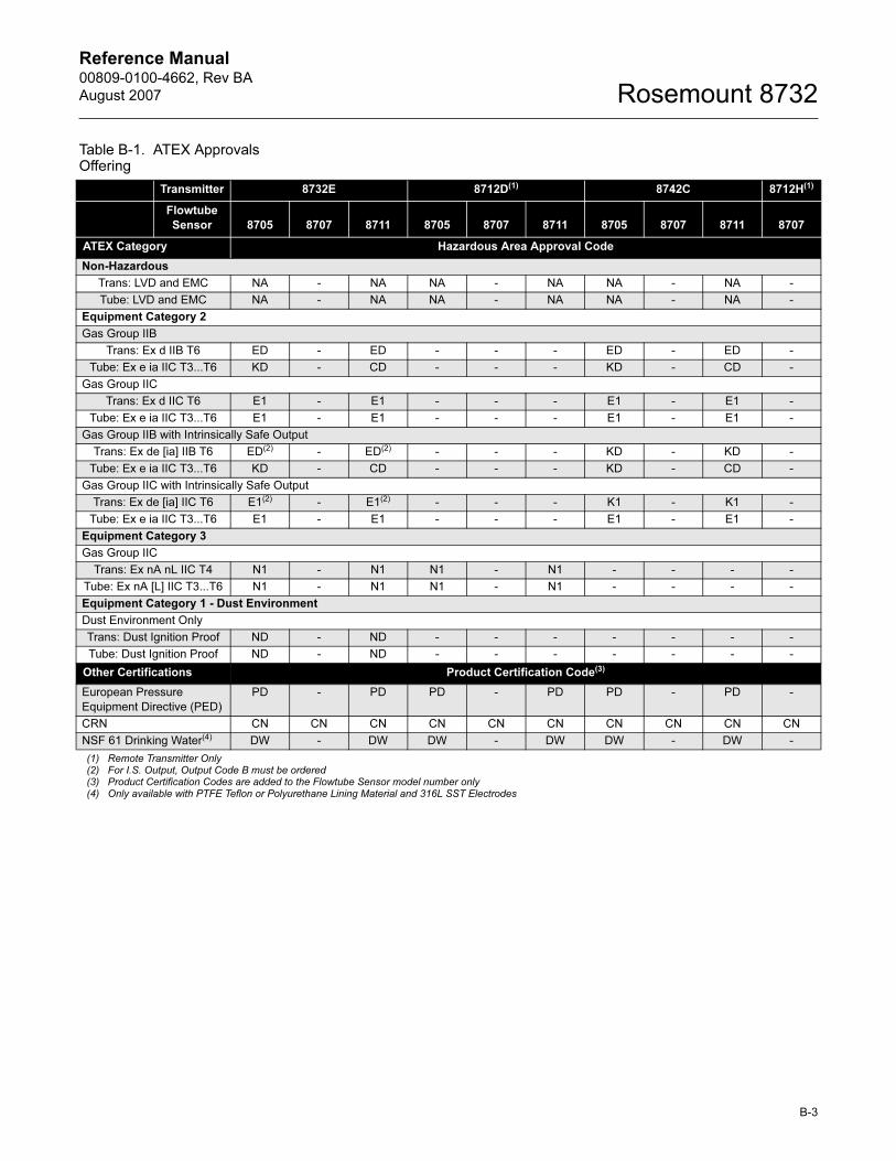
Reference Manual 00809-0100-4662, Rev BA
August 2007 Rosemount 8732
Table B-1. ATEX Approvals Offering
Transmitter 8732E 8712D(1) 8742C 8712H(1)
Flowtube
Sensor 8705 8707 8711 8705 8707 8711 8705 8707 8711 8707
ATEX Category Hazardous Area Approval Code
Non-Hazardous
Trans: LVD and EMC NA - NA NA - NA NA - NA -
Tube: LVD and EMC NA - NA NA - NA NA - NA -
Equipment Category 2
Gas Group IIB
Trans: Ex d IIB T6 ED - ED - - - ED - ED -
Tube: Ex e ia IIC T3...T6 KD - CD - - - KD - CD -
Gas Group IIC
Trans: Ex d IIC T6 E1 - E1 - - - E1 - E1 -
Tube: Ex e ia IIC T3...T6 E1 - E1 - - - E1 - E1 -
Gas Group IIB with Intrinsically Safe Output
Trans: Ex de [ia] IIB T6 ED(2) - ED(2) - - - KD - KD -
Tube: Ex e ia IIC T3...T6 KD - CD - - - KD - CD -
Gas Group IIC with Intrinsically Safe Output
Trans: Ex de [ia] IIC T6 E1(2) - E1(2) - - - K1 - K1 -
Tube: Ex e ia IIC T3...T6 E1 - E1 - - - E1 - E1 -
Equipment Category 3
Gas Group IIC
Trans: Ex nA nL IIC T4 N1 - N1 N1 - N1 - - - -
Tube: Ex nA [L] IIC T3...T6 N1 - N1 N1 - N1 - - - -
Equipment Category 1 - Dust Environment
Dust Environment Only
Trans: Dust Ignition Proof ND - ND - - - - - - -
Tube: Dust Ignition Proof ND - ND - - - - - - -
Other Certifications Product Certification Code(3)
European Pressure
Equipment Directive (PED)
PD - PD PD - PD PD - PD -
CRN CN CN CN CN CN CN CN CN CN CN
NSF 61 Drinking Water(4) DW - DW DW - DW DW - DW -
(1) Remote Transmitter Only(2) For I.S. Output, Output Code B must be ordered(3) Product Certification Codes are added to the Flowtube Sensor model number only(4) Only available with PTFE Teflon or Polyurethane Lining Material and 316L SST Electrodes
B-3
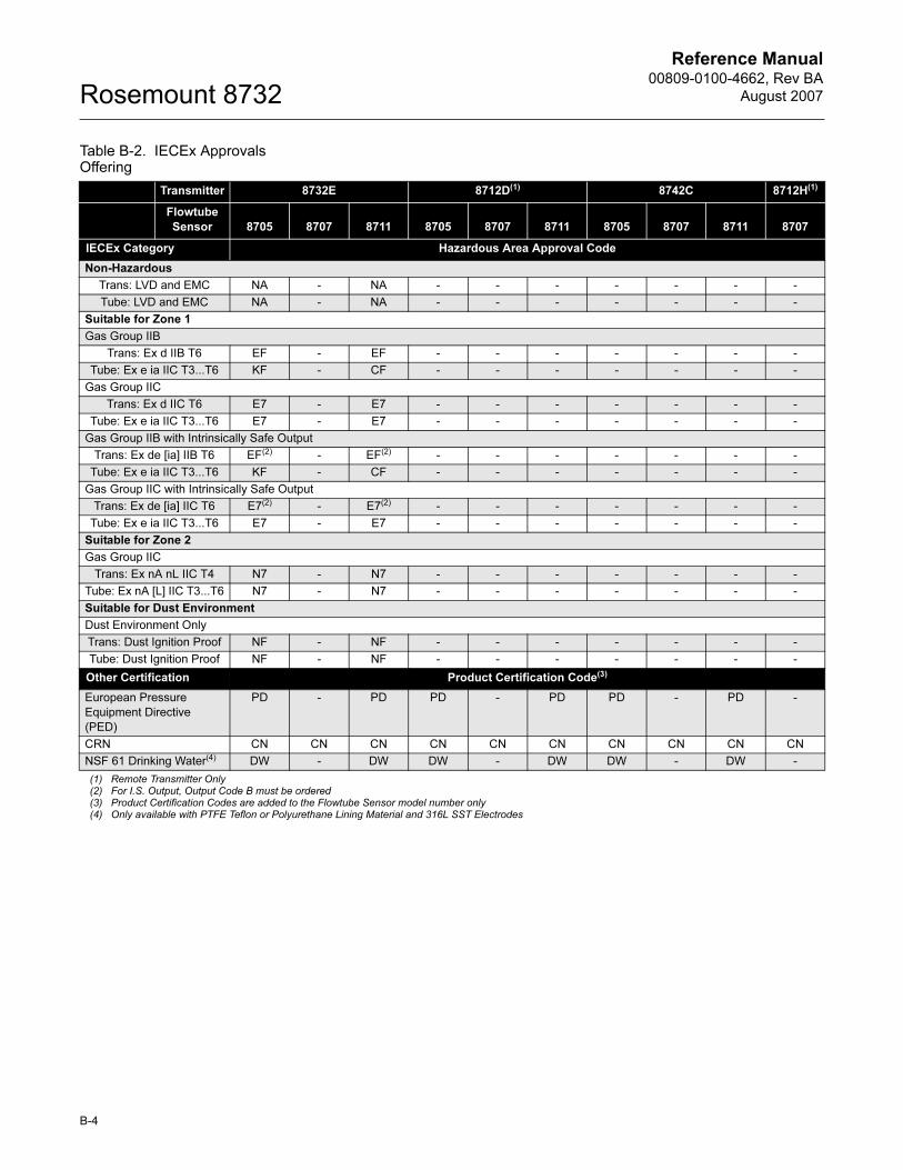
Reference Manual00809-0100-4662, Rev BA
August 2007Rosemount 8732
Table B-2. IECEx Approvals Offering
Transmitter 8732E 8712D(1) 8742C 8712H(1)
Flowtube
Sensor 8705 8707 8711 8705 8707 8711 8705 8707 8711 8707
IECEx Category Hazardous Area Approval Code
Non-Hazardous
Trans: LVD and EMC NA - NA - - - - - - -
Tube: LVD and EMC NA - NA - - - - - - -
Suitable for Zone 1
Gas Group IIB
Trans: Ex d IIB T6 EF - EF - - - - - - -
Tube: Ex e ia IIC T3...T6 KF - CF - - - - - - -
Gas Group IIC
Trans: Ex d IIC T6 E7 - E7 - - - - - - -
Tube: Ex e ia IIC T3...T6 E7 - E7 - - - - - - -
Gas Group IIB with Intrinsically Safe Output
Trans: Ex de [ia] IIB T6 EF(2) - EF(2) - - - - - - -
Tube: Ex e ia IIC T3...T6 KF - CF - - - - - - -
Gas Group IIC with Intrinsically Safe Output
Trans: Ex de [ia] IIC T6 E7(2) - E7(2) - - - - - - -
Tube: Ex e ia IIC T3...T6 E7 - E7 - - - - - - -
Suitable for Zone 2
Gas Group IIC
Trans: Ex nA nL IIC T4 N7 - N7 - - - - - - -
Tube: Ex nA [L] IIC T3...T6 N7 - N7 - - - - - - -
Suitable for Dust Environment
Dust Environment Only
Trans: Dust Ignition Proof NF - NF - - - - - - -
Tube: Dust Ignition Proof NF - NF - - - - - - -
Other Certification Product Certification Code(3)
European Pressure
Equipment Directive
(PED)
PD - PD PD - PD PD - PD -
CRN CN CN CN CN CN CN CN CN CN CN
NSF 61 Drinking Water(4) DW - DW DW - DW DW - DW -
(1) Remote Transmitter Only(2) For I.S. Output, Output Code B must be ordered(3) Product Certification Codes are added to the Flowtube Sensor model number only(4) Only available with PTFE Teflon or Polyurethane Lining Material and 316L SST Electrodes
B-4
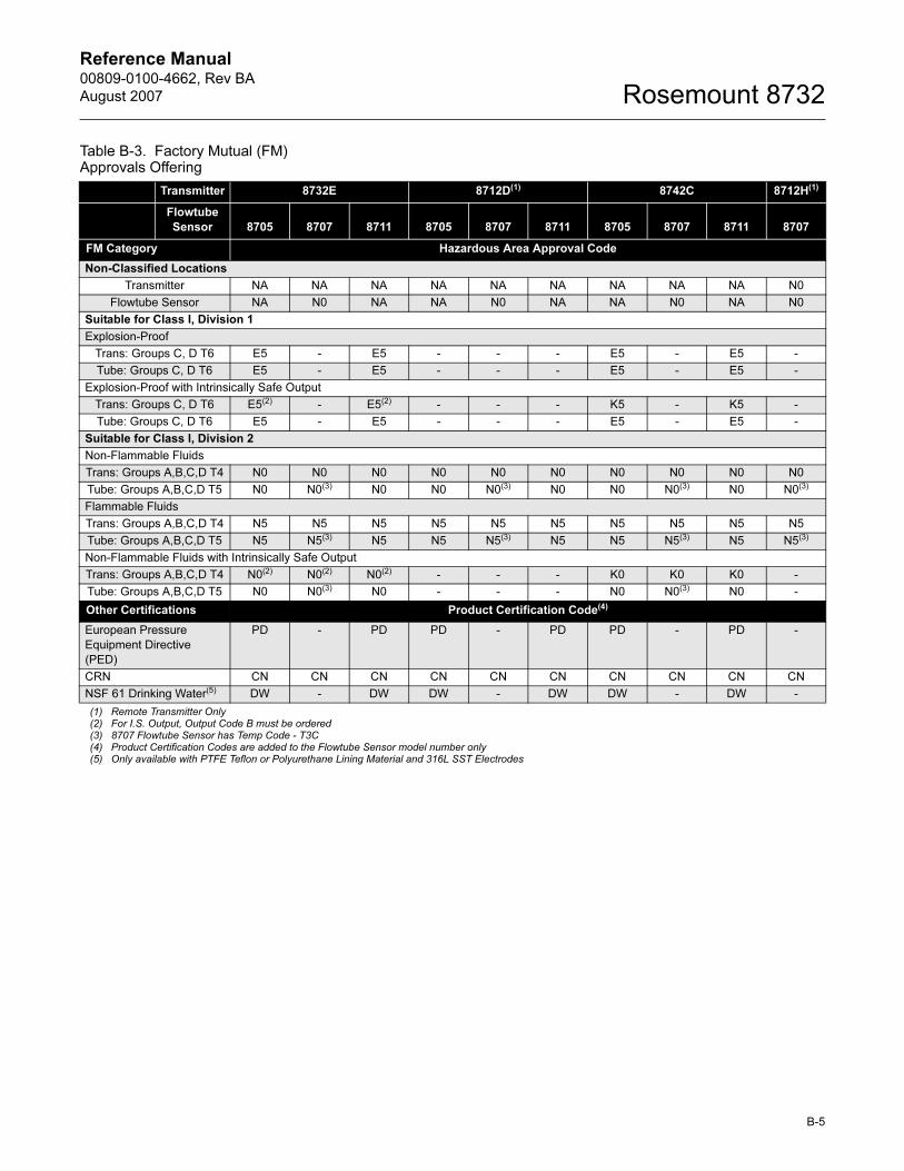
Reference Manual 00809-0100-4662, Rev BA
August 2007 Rosemount 8732
Table B-3. Factory Mutual (FM) Approvals Offering
Transmitter 8732E 8712D(1) 8742C 8712H(1)
Flowtube
Sensor 8705 8707 8711 8705 8707 8711 8705 8707 8711 8707
FM Category Hazardous Area Approval Code
Non-Classified Locations
Transmitter NA NA NA NA NA NA NA NA NA N0
Flowtube Sensor NA N0 NA NA N0 NA NA N0 NA N0
Suitable for Class I, Division 1
Explosion-Proof
Trans: Groups C, D T6 E5 - E5 - - - E5 - E5 -
Tube: Groups C, D T6 E5 - E5 - - - E5 - E5 -
Explosion-Proof with Intrinsically Safe Output
Trans: Groups C, D T6 E5(2) - E5(2) - - - K5 - K5 -
Tube: Groups C, D T6 E5 - E5 - - - E5 - E5 -
Suitable for Class I, Division 2
Non-Flammable Fluids
Trans: Groups A,B,C,D T4 N0 N0 N0 N0 N0 N0 N0 N0 N0 N0
Tube: Groups A,B,C,D T5 N0 N0(3) N0 N0 N0(3) N0 N0 N0(3) N0 N0(3)
Flammable Fluids
Trans: Groups A,B,C,D T4 N5 N5 N5 N5 N5 N5 N5 N5 N5 N5
Tube: Groups A,B,C,D T5 N5 N5(3) N5 N5 N5(3) N5 N5 N5(3) N5 N5(3)
Non-Flammable Fluids with Intrinsically Safe Output
Trans: Groups A,B,C,D T4 N0(2) N0(2) N0(2) - - - K0 K0 K0 -
Tube: Groups A,B,C,D T5 N0 N0(3) N0 - - - N0 N0(3) N0 -
Other Certifications Product Certification Code(4)
European Pressure
Equipment Directive
(PED)
PD - PD PD - PD PD - PD -
CRN CN CN CN CN CN CN CN CN CN CN
NSF 61 Drinking Water(5) DW - DW DW - DW DW - DW -
(1) Remote Transmitter Only(2) For I.S. Output, Output Code B must be ordered(3) 8707 Flowtube Sensor has Temp Code - T3C(4) Product Certification Codes are added to the Flowtube Sensor model number only(5) Only available with PTFE Teflon or Polyurethane Lining Material and 316L SST Electrodes
B-5
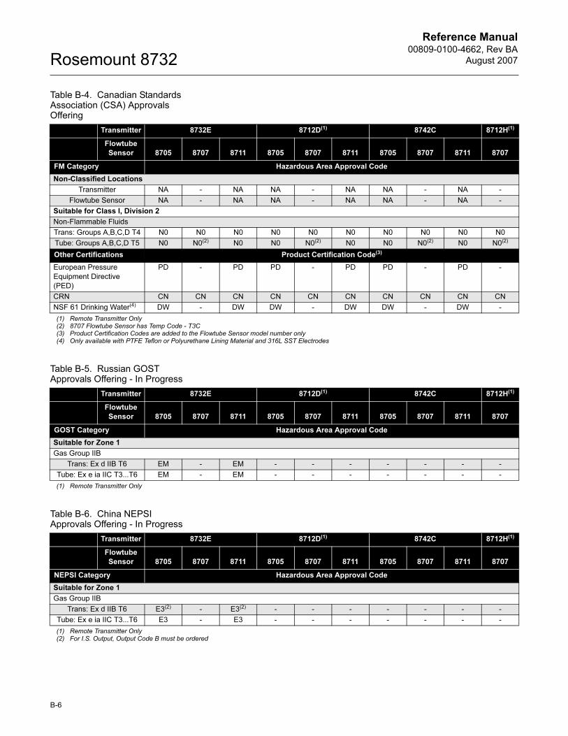
Reference Manual00809-0100-4662, Rev BA
August 2007Rosemount 8732
B-6
Table B-4. Canadian Standards Association (CSA) Approvals Offering
Table B-5. Russian GOST Approvals Offering - In Progress
Table B-6. China NEPSI Approvals Offering - In Progress
Transmitter 8732E 8712D(1) 8742C 8712H(1)
Flowtube
Sensor 8705 8707 8711 8705 8707 8711 8705 8707 8711 8707
FM Category Hazardous Area Approval Code
Non-Classified Locations
Transmitter NA - NA NA - NA NA - NA -
Flowtube Sensor NA - NA NA - NA NA - NA -
Suitable for Class I, Division 2
Non-Flammable Fluids
Trans: Groups A,B,C,D T4 N0 N0 N0 N0 N0 N0 N0 N0 N0 N0
Tube: Groups A,B,C,D T5 N0 N0(2) N0 N0 N0(2) N0 N0 N0(2) N0 N0(2)
Other Certifications Product Certification Code(3)
European Pressure
Equipment Directive
(PED)
PD - PD PD - PD PD - PD -
CRN CN CN CN CN CN CN CN CN CN CN
NSF 61 Drinking Water(4) DW - DW DW - DW DW - DW -
(1) Remote Transmitter Only(2) 8707 Flowtube Sensor has Temp Code - T3C(3) Product Certification Codes are added to the Flowtube Sensor model number only(4) Only available with PTFE Teflon or Polyurethane Lining Material and 316L SST Electrodes
Transmitter 8732E 8712D(1) 8742C 8712H(1)
Flowtube
Sensor 8705 8707 8711 8705 8707 8711 8705 8707 8711 8707
GOST Category Hazardous Area Approval Code
Suitable for Zone 1
Gas Group IIB
Trans: Ex d IIB T6 EM - EM - - - - - - -
Tube: Ex e ia IIC T3...T6 EM - EM - - - - - - -
(1) Remote Transmitter Only
Transmitter 8732E 8712D(1) 8742C 8712H(1)
Flowtube
Sensor 8705 8707 8711 8705 8707 8711 8705 8707 8711 8707
NEPSI Category Hazardous Area Approval Code
Suitable for Zone 1
Gas Group IIB
Trans: Ex d IIB T6 E3(2) - E3(2) - - - - - - -
Tube: Ex e ia IIC T3...T6 E3 - E3 - - - - - - -
(1) Remote Transmitter Only(2) For I.S. Output, Output Code B must be ordered
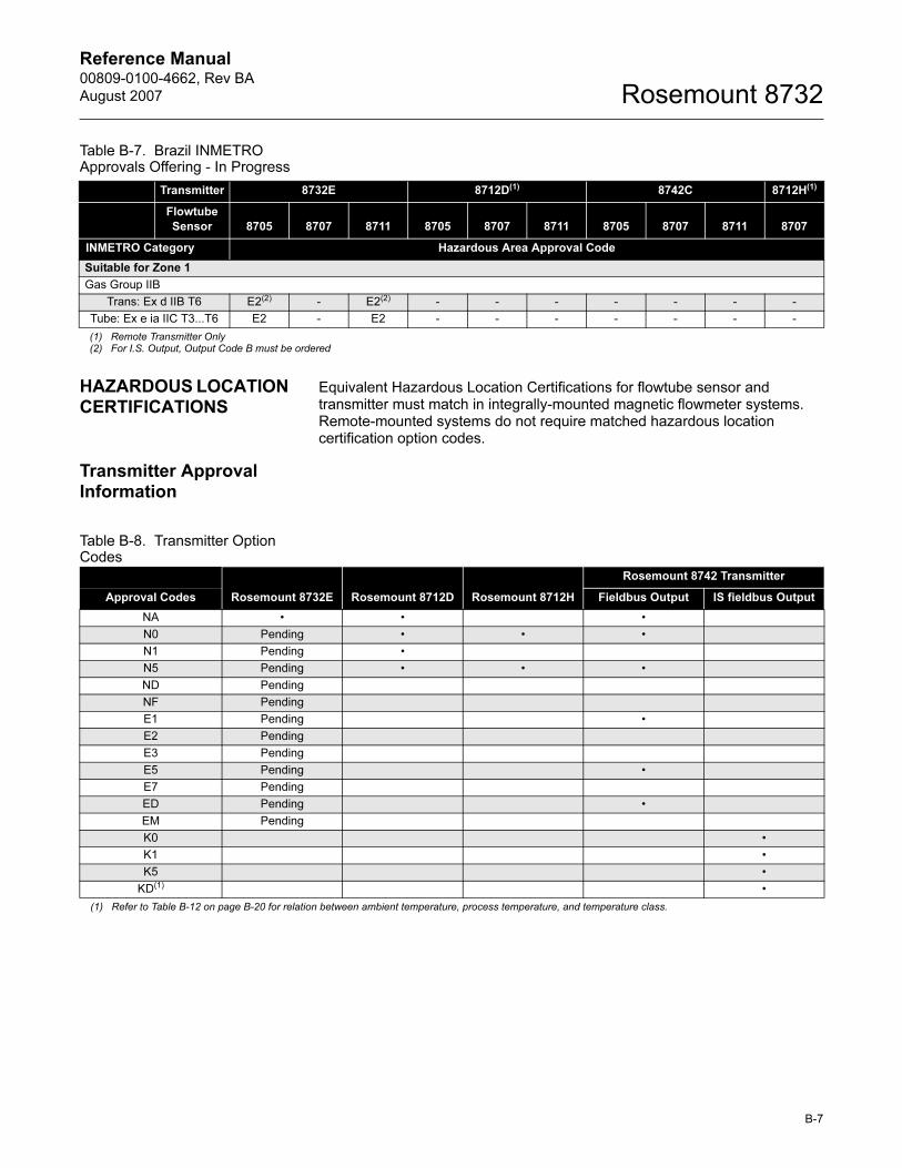
Reference Manual 00809-0100-4662, Rev BA
August 2007 Rosemount 8732
Table B-7. Brazil INMETRO Approvals Offering - In Progress
HAZARDOUS LOCATION CERTIFICATIONS
Equivalent Hazardous Location Certifications for flowtube sensor and transmitter must match in integrally-mounted magnetic flowmeter systems. Remote-mounted systems do not require matched hazardous location certification option codes.
Transmitter Approval Information
Table B-8. Transmitter Option Codes
Transmitter 8732E 8712D(1) 8742C 8712H(1)
Flowtube
Sensor 8705 8707 8711 8705 8707 8711 8705 8707 8711 8707
INMETRO Category Hazardous Area Approval Code
Suitable for Zone 1
Gas Group IIB
Trans: Ex d IIB T6 E2(2) - E2(2) - - - - - - -
Tube: Ex e ia IIC T3...T6 E2 - E2 - - - - - - -
(1) Remote Transmitter Only(2) For I.S. Output, Output Code B must be ordered
Rosemount 8732E Rosemount 8712D Rosemount 8712H
Rosemount 8742 Transmitter
Approval Codes Fieldbus Output IS fieldbus Output
NA • • •
N0 Pending • • •
N1 Pending •
N5 Pending • • •
ND Pending
NF Pending
E1 Pending •
E2 Pending
E3 Pending
E5 Pending •
E7 Pending
ED Pending •
EM Pending
K0 •
K1 •
K5 •
KD(1) •
(1) Refer to Table B-12 on page B-20 for relation between ambient temperature, process temperature, and temperature class.
B-7
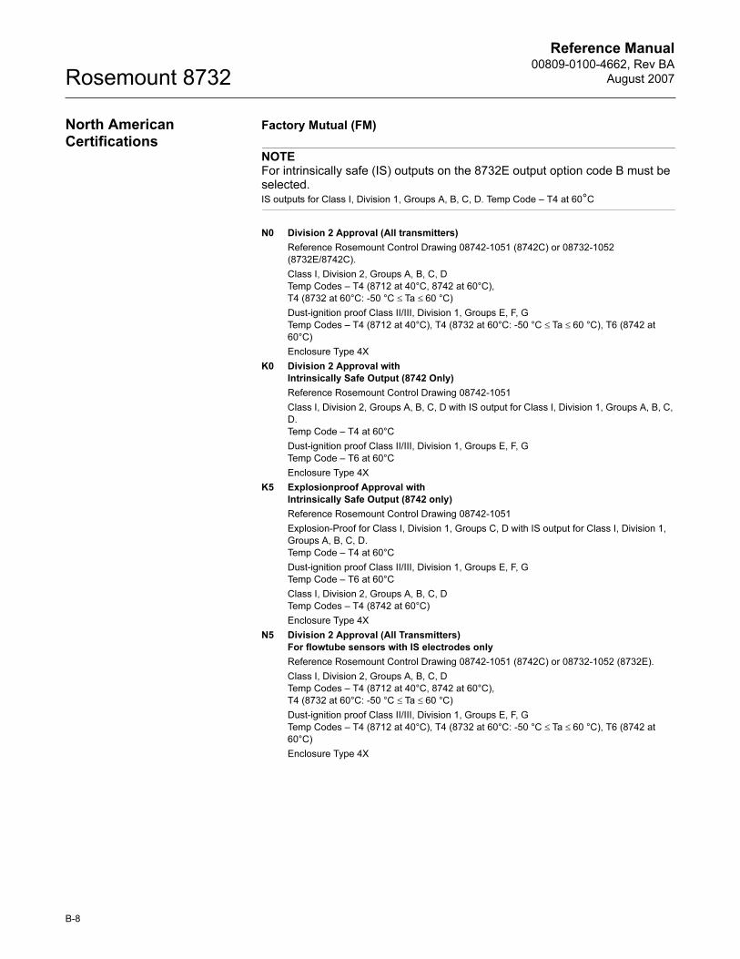
Reference Manual00809-0100-4662, Rev BA
August 2007Rosemount 8732
North American Certifications
Factory Mutual (FM)
NOTEFor intrinsically safe (IS) outputs on the 8732E output option code B must be selected.IS outputs for Class I, Division 1, Groups A, B, C, D. Temp Code – T4 at 60°C
N0 Division 2 Approval (All transmitters)
Reference Rosemount Control Drawing 08742-1051 (8742C) or 08732-1052
(8732E/8742C).
Class I, Division 2, Groups A, B, C, D
Temp Codes – T4 (8712 at 40°C, 8742 at 60°C),
T4 (8732 at 60°C: -50 °C ≤ Ta ≤ 60 °C)
Dust-ignition proof Class II/III, Division 1, Groups E, F, G
Temp Codes – T4 (8712 at 40°C), T4 (8732 at 60°C: -50 °C ≤ Ta ≤ 60 °C), T6 (8742 at
60°C)
Enclosure Type 4X
K0 Division 2 Approval with
Intrinsically Safe Output (8742 Only)
Reference Rosemount Control Drawing 08742-1051
Class I, Division 2, Groups A, B, C, D with IS output for Class I, Division 1, Groups A, B, C,
D.
Temp Code – T4 at 60°C
Dust-ignition proof Class II/III, Division 1, Groups E, F, G
Temp Code – T6 at 60°C
Enclosure Type 4X
K5 Explosionproof Approval with
Intrinsically Safe Output (8742 only)
Reference Rosemount Control Drawing 08742-1051
Explosion-Proof for Class I, Division 1, Groups C, D with IS output for Class I, Division 1,
Groups A, B, C, D.
Temp Code – T4 at 60°C
Dust-ignition proof Class II/III, Division 1, Groups E, F, G
Temp Code – T6 at 60°C
Class I, Division 2, Groups A, B, C, D
Temp Codes – T4 (8742 at 60°C)
Enclosure Type 4X
N5 Division 2 Approval (All Transmitters)
For flowtube sensors with IS electrodes only
Reference Rosemount Control Drawing 08742-1051 (8742C) or 08732-1052 (8732E).
Class I, Division 2, Groups A, B, C, D
Temp Codes – T4 (8712 at 40°C, 8742 at 60°C),
T4 (8732 at 60°C: -50 °C ≤ Ta ≤ 60 °C)
Dust-ignition proof Class II/III, Division 1, Groups E, F, G
Temp Codes – T4 (8712 at 40°C), T4 (8732 at 60°C: -50 °C ≤ Ta ≤ 60 °C), T6 (8742 at
60°C)
Enclosure Type 4X
B-8
Reference Manual 00809-0100-4662, Rev BA
August 2007 Rosemount 8732
E5 Explosion-Proof Approval (8732 and 8742 only)
Reference Rosemount Control Drawing 08732-1052
Explosion-Proof for Class I, Division 1, Groups C, D
Temp Code – T6 at 60°C
Dust-ignition proof Class II/III, Division 1, Groups E, F, G
Temp Code – T6 at 60 °C
Class I, Division 2, Groups A, B, C, D
Temp Codes – T4 (8742 at 60°C), T6 (8732 at 60°C: -50 °C ≤ Ta ≤ 60 °C): with LOI T6
(8732 at 60°C: -40 °C ≤ Ta ≤ 60 °C)
Enclosure Type 4X
Canadian Standards Association (CSA)
N0 Division 2 Approval
Reference Rosemount Control Drawing 08732-1051
(8732E or 8742C only)
Class I, Division 2, Groups A, B, C, D
Temp Codes – T4 (8732 at 60°C: -50 °C ≤ Ta ≤ 60 °C),
T4 (8742 at 60°C)
Dust-ignition proof Class II/III, Division 1, Groups E, F, G
Enclosure Type 4X
K0 Division 2 Approval with
Intrinsically Safe Output (8742 Only)
Reference Rosemount Control Drawing 08742-1052
Class I, Division 2, Groups A, B, C, D with IS output for Class I, Division 1, Groups A, B, C,
D. Temp Code – T4 at 60°C
Dust-ignition proof Class II/III, Division 1, Groups E, F, G
Temp Code – T6 at 60°C
Enclosure Type 4X
B-9
Reference Manual00809-0100-4662, Rev BA
August 2007Rosemount 8732
B-10
European Certifications NOTEFor intrinsically safe (IS) outputs on the 8732E output option code B must be selected.IS outputs for Ex de [ia] IIB or IIC T6
E1 ATEX Flameproof
Hydrogen gas group
8732 - Certificate No.: 03ATEXXXXXX II 2G
Ex de IIC or Ex de [ia] IIC T6 (-20 °C ≤ Ta ≤ +57 °C)
with LOI T6 (-20 °C ≤ Ta ≤ +57 °C)
8742 - Certificate No.: 03ATEX2159X II 2G
EEx de IIB + H2 T6 (-20 °C ≤ Ta ≤ +65 °C)
Vmax = 250 V AC or 42 V DC
0575
ED ATEX Flameproof
8732 - Certificate No.: KEMA03ATEXXXXXX II 2G
Ex de IIB or Ex de [ia] IIB T6 (-20 °C ≤ Ta ≤ +57 °C)
with LOI T6 (-20 °C ≤ Ta ≤ +57 °C)
Vmax = 250 V AC or 42 V DC
0575
ND ATEX Dust
8732 - Certificate No.: KEMA06ATEX0006 II 1D
max ΔT = 40 °K(1)
Amb. Temp. Limits: (-20 °C ≤ Ta ≤ +57 °C)
Vmax = 250 V AC or 42 V DC
IP 66
0575
NOTEMax surface temperature is 40 °C above the ambient temperature conditions. Tmax = 100 °C.
SPECIAL CONDITIONS FOR SAFE USE (KEMA 07ATEX0074 X): If the Rosemount 8732 Flow Transmitter is used integrally with the Rosemount 8705 or 8711 Flowtube Sensors, it shall be assured that the mechanical contact areas of the Flowtube Sensor and Flow Transmitter comply with the requirements for flat joints according to standard EN/IEC 60079-1 clause 5.2.
The relation between ambient temperature, process temperature, and temperature class is to be taken from the table under (15 - description) above. (See Table B-12)
The electrical data is to be taken from the summary under (15 - electrical data) above. (See Table B-11)
If the Rosemount 8732 Flow Transmitter is used integrally with the Junction Box, it shall be assured that the mechanical contact areas of the Junction Box and Flow Transmitter comply with the requirements for flanged joints according to standard EN/IEC 60079-1 clause 5.2.
(1) Max surface temperature is 40 °C above the ambient temperature conditions. Tmax = 100
°C
Reference Manual 00809-0100-4662, Rev BA
August 2007 Rosemount 8732
Per EN60079-1: 2004 the gap of the joint between transmitter and remote junction box/flowtube sensor is less than required per table 1 clause 5.2.2; and is only approved for use with approved Rosemount transmitter and approved junction box/flowtube sensor, please consult Rosemount, Inc.
INSTALLATION INSTRUCTIONS:The cable and conduit entry devices and blanking elements shall be of a certified flameproof type, suitable for the conditions of use and correctly installed. With the use of conduit, a certified stopping box shall be provided immediately to the entrance of the enclosure.
ED 8742 - Certificate No: KEMA03ATEX2159X II 2G
EEx de IIB T6 (Ta = -20 °C to +65 °C)
Vmax = 250 V AC or 50 V DC
0575
B-11
Reference Manual00809-0100-4662, Rev BA
August 2007Rosemount 8732
K1 ATEX Flameproof
Hydrogen Gas Group with
Intrinsically safe output (8742 only)
Certificate No.: KEMA03ATEX2159x II 2G
ATEX EEx de [ia] IIB + H2 T6 (-20 °C ≤ Ta ≤ +57 °C)
Vmax = 250 V AC or 50 V DC
0575
See Table 12 for Electrical Parameters
KD ATEX Flameproof with
Intrinsically Safe Output (8742 only)
Certificate No: KEMA03ATEX2159X II 2G
EEx de [ia] IIB T6 (Ta = -20 °C to +57 °C)
Vmax = 250 V AC or 50 V DC
0575
See Table B-11 for Electrical Parameters
SPECIAL CONDITIONS FOR SAFE USE (X) (03ATEX2159X): The relation between ambient temperature, process temperature and temperature class is to be taken from the table under (15 - description) above. (See Table B-12).
If the Rosemount 8742C Flow Transmitter is used integrally with the Junction Box, it shall be assured that the mechanical contact areas of the Junction Box and Flow Transmitter comply with the requirements for flanged joints according to standard EN 50018, clause 5.2.
INSTALLATION INSTRUCTIONS: The cable and conduit entry devices and the closing elements shall be of a certified increased safety type, suitable for the conditions of use and correctly installed.
At ambient temperatures above 50 °C, the flow meter shall be used with heat resistant cables with a temperature rating of at least 90 °C.
A Junction Box in type of explosion protection increased safety “e” may be attached to the base of the Rosemount 8742C Flow Transmitter, permitting remote mounting of the Rosemount 8705 and 8711 Flowtube Sensors.
Ambient temperature range of the Junction Box: -20°C to +65°C.
The Junction Box is classified as II 2 G EEx e IIB T6 and certified under KEMA 03ATEX2052X.
N1 ATEX Type n
8712D - ATEX Certificate No: BASEEFA 05ATEX0170X
EEx nA nL IIC T4
Vmax = 250 V AC or 50 V DC
0575
8732 - ATEX Certificate No: BASEEFA 05ATEXXXXXX
Ex nA nL IIC T4
Vmax = 250 V AC or 42 V DC
0575
B-12
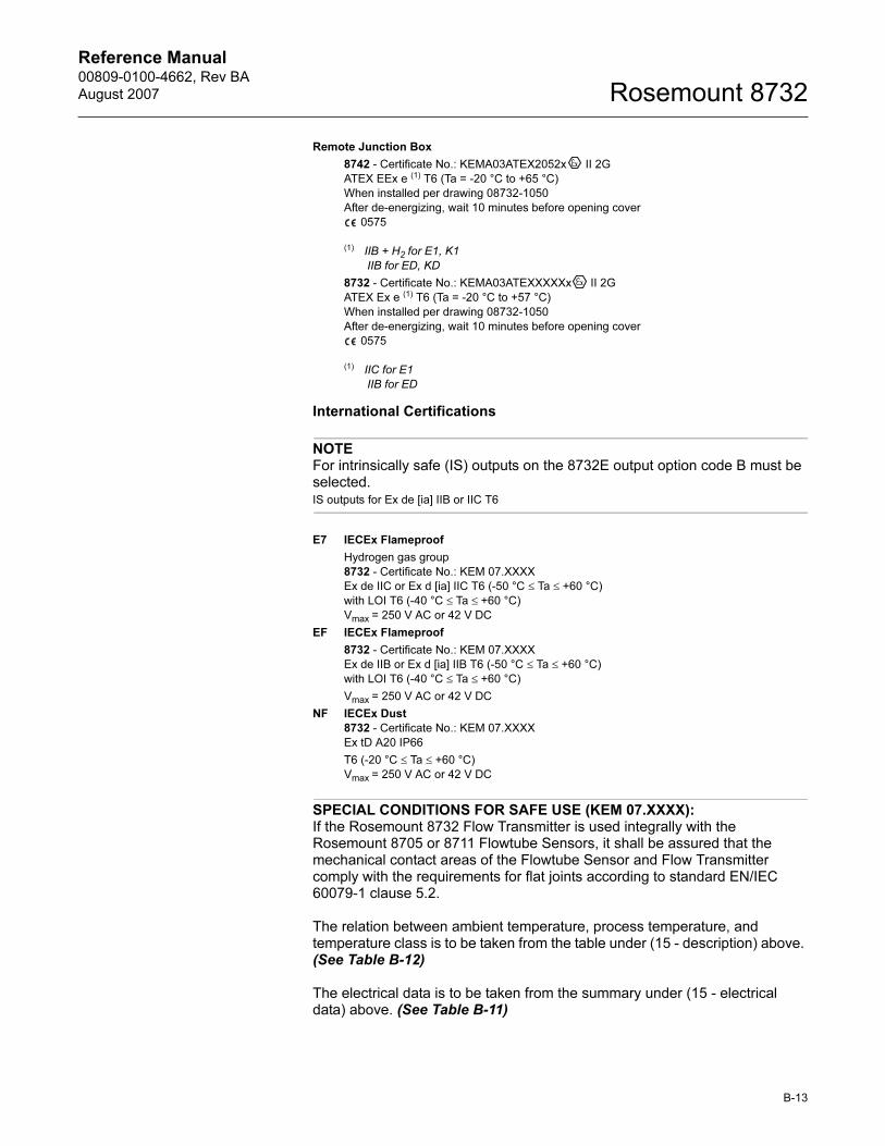
Reference Manual 00809-0100-4662, Rev BA
August 2007 Rosemount 8732
Remote Junction Box
8742 - Certificate No.: KEMA03ATEX2052x II 2G
ATEX EEx e (1) T6 (Ta = -20 °C to +65 °C)
When installed per drawing 08732-1050
After de-energizing, wait 10 minutes before opening cover
0575
(1) IIB + H2 for E1, K1
IIB for ED, KD
8732 - Certificate No.: KEMA03ATEXXXXXx II 2G
ATEX Ex e (1) T6 (Ta = -20 °C to +57 °C)
When installed per drawing 08732-1050
After de-energizing, wait 10 minutes before opening cover
0575
(1) IIC for E1
IIB for ED
International Certifications
NOTEFor intrinsically safe (IS) outputs on the 8732E output option code B must be selected.IS outputs for Ex de [ia] IIB or IIC T6
E7 IECEx Flameproof
Hydrogen gas group
8732 - Certificate No.: KEM 07.XXXX
Ex de IIC or Ex d [ia] IIC T6 (-50 °C ≤ Ta ≤ +60 °C)
with LOI T6 (-40 °C ≤ Ta ≤ +60 °C)
Vmax = 250 V AC or 42 V DC
EF IECEx Flameproof
8732 - Certificate No.: KEM 07.XXXX
Ex de IIB or Ex d [ia] IIB T6 (-50 °C ≤ Ta ≤ +60 °C)
with LOI T6 (-40 °C ≤ Ta ≤ +60 °C)
Vmax = 250 V AC or 42 V DC
NF IECEx Dust
8732 - Certificate No.: KEM 07.XXXX
Ex tD A20 IP66
T6 (-20 °C ≤ Ta ≤ +60 °C)
Vmax = 250 V AC or 42 V DC
SPECIAL CONDITIONS FOR SAFE USE (KEM 07.XXXX): If the Rosemount 8732 Flow Transmitter is used integrally with the Rosemount 8705 or 8711 Flowtube Sensors, it shall be assured that the mechanical contact areas of the Flowtube Sensor and Flow Transmitter comply with the requirements for flat joints according to standard EN/IEC 60079-1 clause 5.2.
The relation between ambient temperature, process temperature, and temperature class is to be taken from the table under (15 - description) above. (See Table B-12)
The electrical data is to be taken from the summary under (15 - electrical data) above. (See Table B-11)
B-13
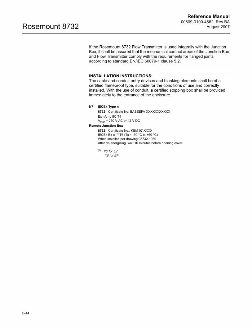
Reference Manual00809-0100-4662, Rev BA
August 2007Rosemount 8732
If the Rosemount 8732 Flow Transmitter is used integrally with the Junction Box, it shall be assured that the mechanical contact areas of the Junction Box and Flow Transmitter comply with the requirements for flanged joints according to standard EN/IEC 60079-1 clause 5.2.
INSTALLATION INSTRUCTIONS:The cable and conduit entry devices and blanking elements shall be of a certified flameproof type, suitable for the conditions of use and correctly installed. With the use of conduit, a certified stopping box shall be provided immediately to the entrance of the enclosure.
N7 IECEx Type n
8732 - Certificate No: BASEEFA XXXXXXXXXXX
Ex nA nL IIC T4
Vmax = 250 V AC or 42 V DC
Remote Junction Box
8732 - Certificate No.: KEM 07.XXXX
IECEx Ex e (1) T6 (Ta = -50 °C to +60 °C)
When installed per drawing 08732-1050
After de-energizing, wait 10 minutes before opening cover
(1) IIC for E7
IIB for EF
B-14
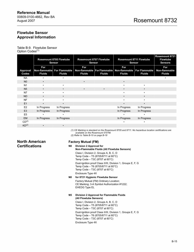
Reference Manual 00809-0100-4662, Rev BA
August 2007 Rosemount 8732
Flowtube Sensor Approval Information
Table B-9. Flowtube Sensor Option Codes(1)
(1) CE Marking is standard on the Rosemount 8705 and 8711. No hazardous location certifications are available on the Rosemount 570TM.
(2) Refer to Table B-10 on page B-18
North American Certifications
Factory Mutual (FM)
N0 Division 2 Approval for
Non-Flammable Fluids (All Flowtube Sensors)
Class I, Division 2, Groups A, B, C, D
Temp Code – T5 (8705/8711 at 60°C)
Temp Code – T3C (8707 at 60°C)
Dust-Ignition proof Class II/III, Division 1, Groups E, F, G
Temp Code – T6 (8705/8711 at 60°C)
Temp Code – T3C (8707 at 60°C)
Enclosure Type 4X
N0 for 8721 Hygienic Flowtube Sensor
Factory Mutual (FM) Ordinary Location;
CE Marking; 3-A Symbol Authorization #1222;
EHEDG Type EL
N5 Division 2 Approval for Flammable Fluids
(All Flowtube Sensors)
Class I, Division 2, Groups A, B, C, D
Temp Code – T5 (8705/8711 at 60°C)
Temp Code – T3C (8707 at 60°C)
Dust-Ignition proof Class II/III, Division 1, Groups E, F, G
Temp Code – T6 (8705/8711 at 60°C)
Temp Code – T3C (8707 at 60°C)
Enclosure Type 4X
Approval
Codes
Rosemount 8705 Flowtube
Sensor
Rosemount 8707 Flowtube
Sensor
Rosemount 8711 Flowtube
Sensor
Rosemount 8721
Flowtube
Sensors
For
Non-flammable
Fluids
For Flammable
Fluids
For
Non-flammable
Fluids
For Flammable
Fluids
For
Non-flammable
Fluids
For Flammable
Fluids
For
Non-flammable
Fluids
NA • • •
N0 • • •
N1 • • • •
N5 • • • • • •
N7 • • • •
ND • • • •
NF • • • •
E1 • • • •
E2 In Progress In Progress In Progress In Progress
E3 In Progress In Progress In Progress In Progress
E5 • • • •
EM In Progress In Progress In Progress In Progress
CD(2) • •
KD(2) • •
B-15
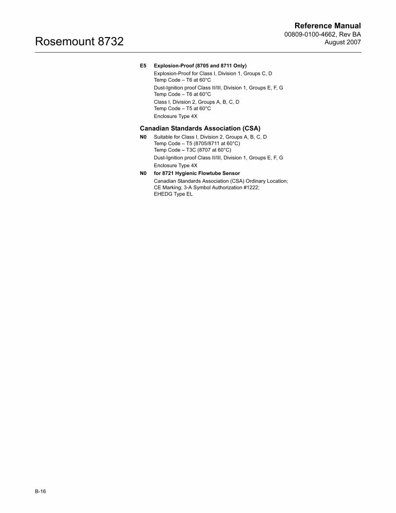
Reference Manual00809-0100-4662, Rev BA
August 2007Rosemount 8732
E5 Explosion-Proof (8705 and 8711 Only)
Explosion-Proof for Class I, Division 1, Groups C, D
Temp Code – T6 at 60°C
Dust-Ignition proof Class II/III, Division 1, Groups E, F, G
Temp Code – T6 at 60°C
Class I, Division 2, Groups A, B, C, D
Temp Code – T5 at 60°C
Enclosure Type 4X
Canadian Standards Association (CSA)
N0 Suitable for Class I, Division 2, Groups A, B, C, D
Temp Code – T5 (8705/8711 at 60°C)
Temp Code – T3C (8707 at 60°C)
Dust-Ignition proof Class II/III, Division 1, Groups E, F, G
Enclosure Type 4X
N0 for 8721 Hygienic Flowtube Sensor
Canadian Standards Association (CSA) Ordinary Location;
CE Marking; 3-A Symbol Authorization #1222;
EHEDG Type EL
B-16
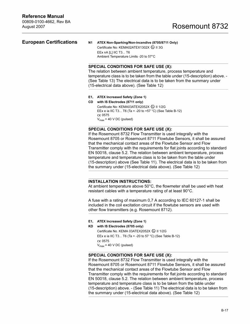
Reference Manual 00809-0100-4662, Rev BA
August 2007 Rosemount 8732
European Certifications N1 ATEX Non-Sparking/Non-incendive (8705/8711 Only)
Certificate No: KEMA02ATEX1302X II 3G
EEx nA [L] IIC T3... T6
Ambient Temperature Limits -20 to 57°C
SPECIAL CONDITIONS FOR SAFE USE (X):The relation between ambient temperature, process temperature and temperature class is to be taken from the table under (15-description) above. - (See Table 13) The electrical data is to be taken from the summary under (15-electrical data above). (See Table 12)
E1, ATEX Increased Safety (Zone 1)
CD with IS Electrodes (8711 only)
Certificate No: KEMA03ATEX2052X II 1/2G
EEx e ia IIC T3... T6 (Ta = -20 to +57 °C) (See Table B-12)
0575
Vmax = 40 V DC (pulsed)
SPECIAL CONDITIONS FOR SAFE USE (X):If the Rosemount 8732 Flow Transmitter is used integrally with the Rosemount 8705 or Rosemount 8711 Flowtube Sensors, it shall be assured that the mechanical contact areas of the Flowtube Sensor and Flow Transmitter comply with the requirements for flat joints according to standard EN 50018, clause 5.2. The relation between ambient temperature, process temperature and temperature class is to be taken from the table under (15-description) above (See Table 11). The electrical data is to be taken from the summary under (15-electrical data above). (See Table 12)
INSTALLATION INSTRUCTIONS:At ambient temperature above 50°C, the flowmeter shall be used with heat resistant cables with a temperature rating of at least 90°C.
A fuse with a rating of maximum 0,7 A according to IEC 60127-1 shall be included in the coil excitation circuit if the flowtube sensors are used with other flow transmitters (e.g. Rosemount 8712).
E1, ATEX Increased Safety (Zone 1)
KD with IS Electrodes (8705 only)
Certificate No. KEMA 03ATEX2052X II 1/2G
EEx e ia IIC T3... T6 (Ta = -20 to 57 °C) (See Table B-12)
0575
Vmax = 40 V DC (pulsed)
SPECIAL CONDITIONS FOR SAFE USE (X):If the Rosemount 8732 Flow Transmitter is used integrally with the Rosemount 8705 or Rosemount 8711 Flowtube Sensors, it shall be assured that the mechanical contact areas of the Flowtube Sensor and Flow Transmitter comply with the requirements for flat joints according to standard EN 50018, clause 5.2. The relation between ambient temperature, process temperature and temperature class is to be taken from the table under (15-description) above. - (See Table 11) The electrical data is to be taken from the summary under (15-electrical data above). (See Table 12)
B-17
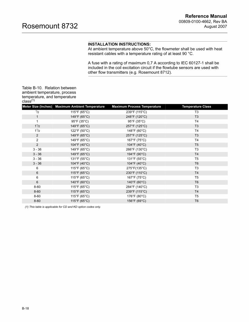
Reference Manual00809-0100-4662, Rev BA
August 2007Rosemount 8732
INSTALLATION INSTRUCTIONS:At ambient temperature above 50°C, the flowmeter shall be used with heat resistant cables with a temperature rating of at least 90 °C.
A fuse with a rating of maximum 0,7 A according to IEC 60127-1 shall be included in the coil excitation circuit if the flowtube sensors are used with other flow transmitters (e.g. Rosemount 8712).
Table B-10. Relation between ambient temperature, process temperature, and temperature class(1)
(1) This table is applicable for CD and KD option codes only.
Meter Size (Inches) Maximum Ambient Temperature Maximum Process Temperature Temperature Class
1/2 115°F (65°C) 239°F (115°C) T3
1 149°F (65°C) 248°F (120°C) T3
1 95°F (35°C) 95°F (35°C) T4
11/2 149°F (65°C) 257°F (125°C) T3
11/2 122°F (50°C) 148°F (60°C) T4
2 149°F (65°C) 257°F (125°C) T3
2 149°F (65°C) 167°F (75°C) T4
2 104°F (40°C) 104°F (40°C) T5
3 - 36 149°F (65°C) 266°F (130°C) T3
3 - 36 149°F (65°C) 194°F (90°C) T4
3 - 36 131°F (55°C) 131°F (55°C) T5
3 - 36 104°F (40°C) 104°F (40°C) T6
6 115°F (65°C) 275°F(135°C) T3
6 115°F (65°C) 230°F (110°C) T4
6 115°F (65°C) 167°F (75°C) T5
6 140°F (60°C) 140°F (60°C) T6
8-60 115°F (65°C) 284°F (140°C) T3
8-60 115°F (65°C) 239°F (115°C) T4
8-60 115°F (65°C) 176°F (80°C) T5
8-60 115°F (65°C) 156°F (69°C) T6
B-18
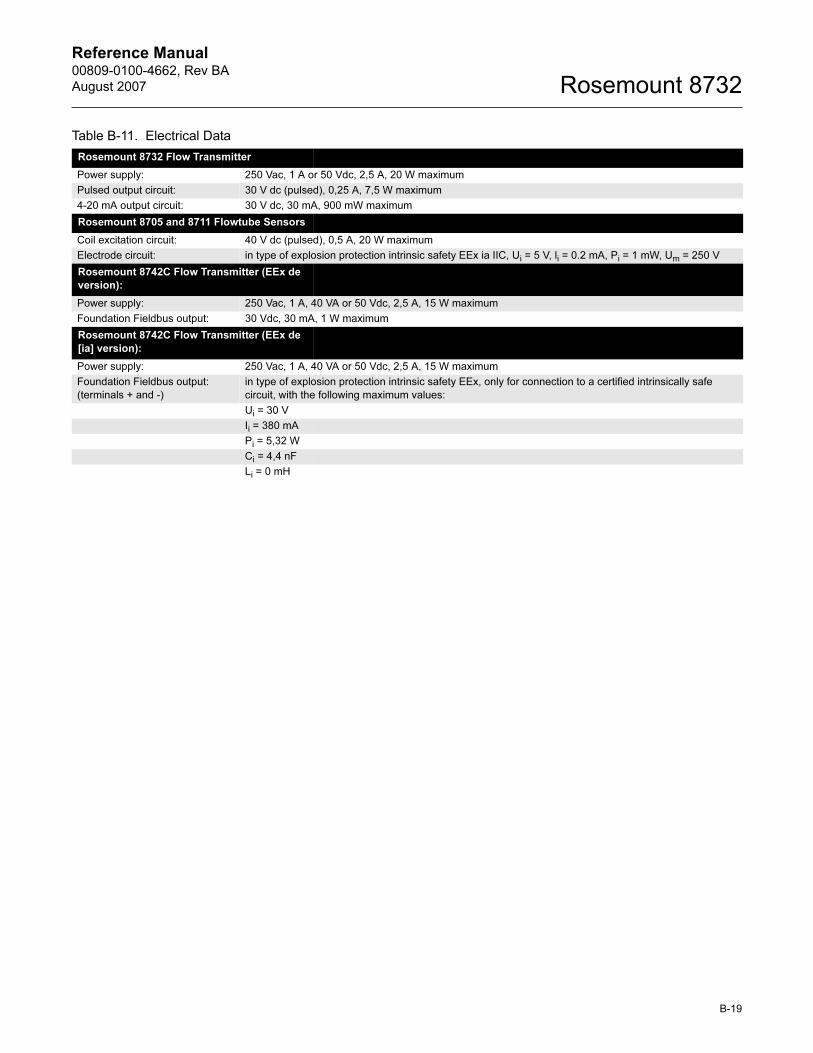
Reference Manual 00809-0100-4662, Rev BA
August 2007 Rosemount 8732
Table B-11. Electrical Data
Rosemount 8732 Flow Transmitter
Power supply: 250 Vac, 1 A or 50 Vdc, 2,5 A, 20 W maximum
Pulsed output circuit: 30 V dc (pulsed), 0,25 A, 7,5 W maximum
4-20 mA output circuit: 30 V dc, 30 mA, 900 mW maximum
Rosemount 8705 and 8711 Flowtube Sensors
Coil excitation circuit: 40 V dc (pulsed), 0,5 A, 20 W maximum
Electrode circuit: in type of explosion protection intrinsic safety EEx ia IIC, Ui = 5 V, li = 0.2 mA, Pi = 1 mW, Um = 250 V
Rosemount 8742C Flow Transmitter (EEx de
version):
Power supply: 250 Vac, 1 A, 40 VA or 50 Vdc, 2,5 A, 15 W maximum
Foundation Fieldbus output: 30 Vdc, 30 mA, 1 W maximum
Rosemount 8742C Flow Transmitter (EEx de
[ia] version):
Power supply: 250 Vac, 1 A, 40 VA or 50 Vdc, 2,5 A, 15 W maximum
Foundation Fieldbus output:
(terminals + and -)
in type of explosion protection intrinsic safety EEx, only for connection to a certified intrinsically safe
circuit, with the following maximum values:
Ui = 30 V
Ii = 380 mA
Pi = 5,32 W
Ci = 4,4 nF
Li = 0 mH
B-19
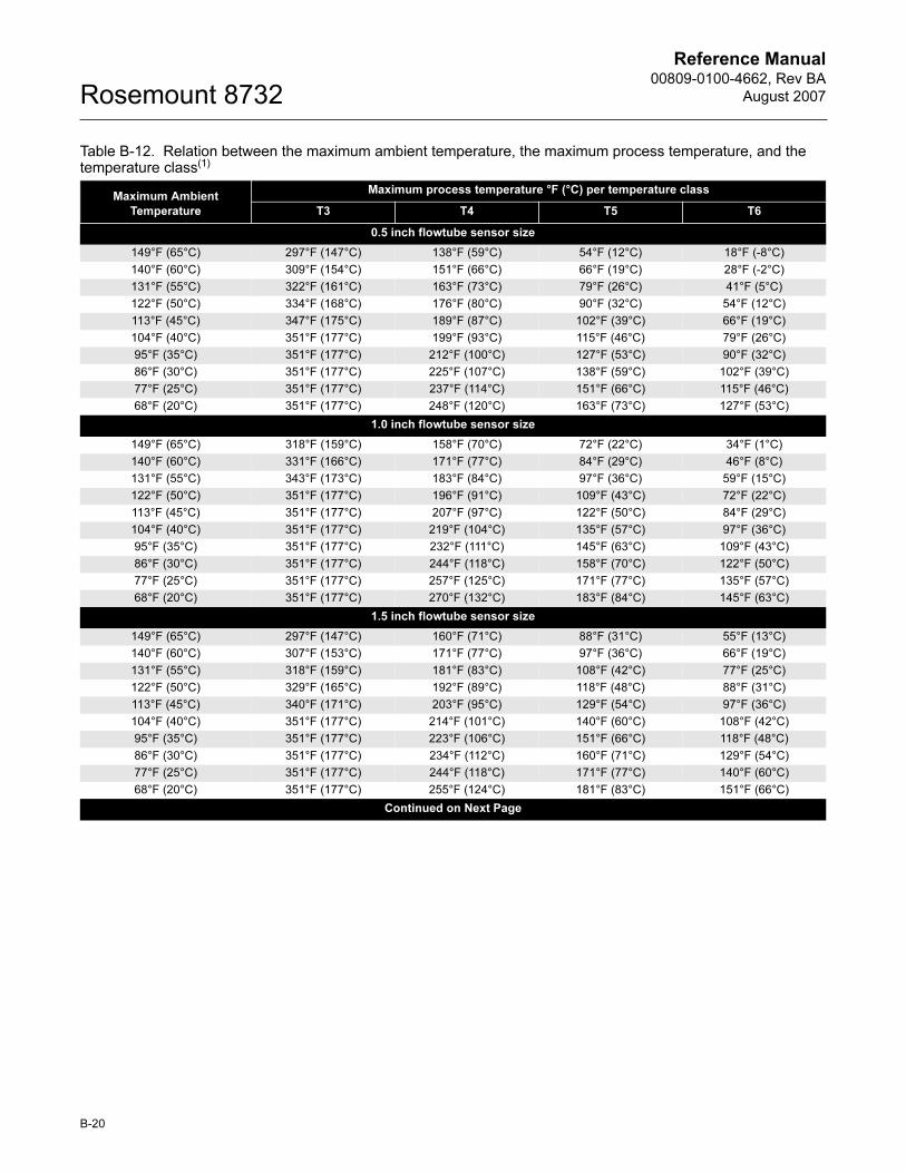
Reference Manual00809-0100-4662, Rev BA
August 2007Rosemount 8732
Table B-12. Relation between the maximum ambient temperature, the maximum process temperature, and the temperature class(1)
Maximum Ambient
Temperature
Maximum process temperature °F (°C) per temperature class
T3 T4 T5 T6
0.5 inch flowtube sensor size
149°F (65°C) 297°F (147°C) 138°F (59°C) 54°F (12°C) 18°F (-8°C)
140°F (60°C) 309°F (154°C) 151°F (66°C) 66°F (19°C) 28°F (-2°C)
131°F (55°C) 322°F (161°C) 163°F (73°C) 79°F (26°C) 41°F (5°C)
122°F (50°C) 334°F (168°C) 176°F (80°C) 90°F (32°C) 54°F (12°C)
113°F (45°C) 347°F (175°C) 189°F (87°C) 102°F (39°C) 66°F (19°C)
104°F (40°C) 351°F (177°C) 199°F (93°C) 115°F (46°C) 79°F (26°C)
95°F (35°C) 351°F (177°C) 212°F (100°C) 127°F (53°C) 90°F (32°C)
86°F (30°C) 351°F (177°C) 225°F (107°C) 138°F (59°C) 102°F (39°C)
77°F (25°C) 351°F (177°C) 237°F (114°C) 151°F (66°C) 115°F (46°C)
68°F (20°C) 351°F (177°C) 248°F (120°C) 163°F (73°C) 127°F (53°C)
1.0 inch flowtube sensor size
149°F (65°C) 318°F (159°C) 158°F (70°C) 72°F (22°C) 34°F (1°C)
140°F (60°C) 331°F (166°C) 171°F (77°C) 84°F (29°C) 46°F (8°C)
131°F (55°C) 343°F (173°C) 183°F (84°C) 97°F (36°C) 59°F (15°C)
122°F (50°C) 351°F (177°C) 196°F (91°C) 109°F (43°C) 72°F (22°C)
113°F (45°C) 351°F (177°C) 207°F (97°C) 122°F (50°C) 84°F (29°C)
104°F (40°C) 351°F (177°C) 219°F (104°C) 135°F (57°C) 97°F (36°C)
95°F (35°C) 351°F (177°C) 232°F (111°C) 145°F (63°C) 109°F (43°C)
86°F (30°C) 351°F (177°C) 244°F (118°C) 158°F (70°C) 122°F (50°C)
77°F (25°C) 351°F (177°C) 257°F (125°C) 171°F (77°C) 135°F (57°C)
68°F (20°C) 351°F (177°C) 270°F (132°C) 183°F (84°C) 145°F (63°C)
1.5 inch flowtube sensor size
149°F (65°C) 297°F (147°C) 160°F (71°C) 88°F (31°C) 55°F (13°C)
140°F (60°C) 307°F (153°C) 171°F (77°C) 97°F (36°C) 66°F (19°C)
131°F (55°C) 318°F (159°C) 181°F (83°C) 108°F (42°C) 77°F (25°C)
122°F (50°C) 329°F (165°C) 192°F (89°C) 118°F (48°C) 88°F (31°C)
113°F (45°C) 340°F (171°C) 203°F (95°C) 129°F (54°C) 97°F (36°C)
104°F (40°C) 351°F (177°C) 214°F (101°C) 140°F (60°C) 108°F (42°C)
95°F (35°C) 351°F (177°C) 223°F (106°C) 151°F (66°C) 118°F (48°C)
86°F (30°C) 351°F (177°C) 234°F (112°C) 160°F (71°C) 129°F (54°C)
77°F (25°C) 351°F (177°C) 244°F (118°C) 171°F (77°C) 140°F (60°C)
68°F (20°C) 351°F (177°C) 255°F (124°C) 181°F (83°C) 151°F (66°C)
Continued on Next Page
B-20
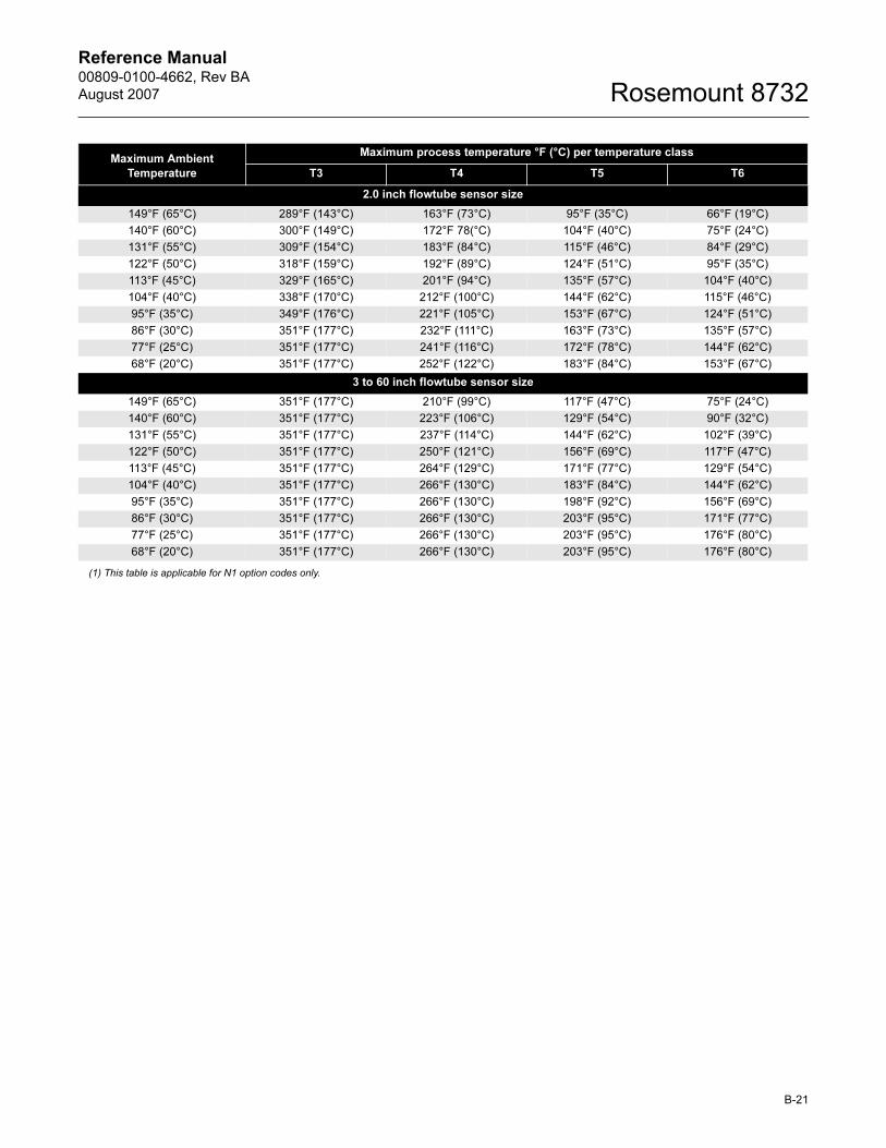
Reference Manual 00809-0100-4662, Rev BA
August 2007 Rosemount 8732
(1) This table is applicable for N1 option codes only.
2.0 inch flowtube sensor size
149°F (65°C) 289°F (143°C) 163°F (73°C) 95°F (35°C) 66°F (19°C)
140°F (60°C) 300°F (149°C) 172°F 78(°C) 104°F (40°C) 75°F (24°C)
131°F (55°C) 309°F (154°C) 183°F (84°C) 115°F (46°C) 84°F (29°C)
122°F (50°C) 318°F (159°C) 192°F (89°C) 124°F (51°C) 95°F (35°C)
113°F (45°C) 329°F (165°C) 201°F (94°C) 135°F (57°C) 104°F (40°C)
104°F (40°C) 338°F (170°C) 212°F (100°C) 144°F (62°C) 115°F (46°C)
95°F (35°C) 349°F (176°C) 221°F (105°C) 153°F (67°C) 124°F (51°C)
86°F (30°C) 351°F (177°C) 232°F (111°C) 163°F (73°C) 135°F (57°C)
77°F (25°C) 351°F (177°C) 241°F (116°C) 172°F (78°C) 144°F (62°C)
68°F (20°C) 351°F (177°C) 252°F (122°C) 183°F (84°C) 153°F (67°C)
3 to 60 inch flowtube sensor size
149°F (65°C) 351°F (177°C) 210°F (99°C) 117°F (47°C) 75°F (24°C)
140°F (60°C) 351°F (177°C) 223°F (106°C) 129°F (54°C) 90°F (32°C)
131°F (55°C) 351°F (177°C) 237°F (114°C) 144°F (62°C) 102°F (39°C)
122°F (50°C) 351°F (177°C) 250°F (121°C) 156°F (69°C) 117°F (47°C)
113°F (45°C) 351°F (177°C) 264°F (129°C) 171°F (77°C) 129°F (54°C)
104°F (40°C) 351°F (177°C) 266°F (130°C) 183°F (84°C) 144°F (62°C)
95°F (35°C) 351°F (177°C) 266°F (130°C) 198°F (92°C) 156°F (69°C)
86°F (30°C) 351°F (177°C) 266°F (130°C) 203°F (95°C) 171°F (77°C)
77°F (25°C) 351°F (177°C) 266°F (130°C) 203°F (95°C) 176°F (80°C)
68°F (20°C) 351°F (177°C) 266°F (130°C) 203°F (95°C) 176°F (80°C)
Maximum Ambient
Temperature
Maximum process temperature °F (°C) per temperature class
T3 T4 T5 T6
B-21

Reference Manual00809-0100-4662, Rev BA
August 2007Rosemount 8732
B-22
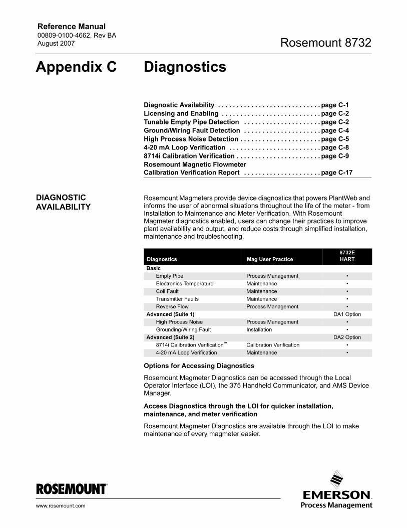
Reference Manual 00809-0100-4662, Rev BA
August 2007 Rosemount 8732
Appendix C Diagnostics
Diagnostic Availability . . . . . . . . . . . . . . . . . . . . . . . . . . . . page C-1
Licensing and Enabling . . . . . . . . . . . . . . . . . . . . . . . . . . . page C-2
Tunable Empty Pipe Detection . . . . . . . . . . . . . . . . . . . . . page C-2
Ground/Wiring Fault Detection . . . . . . . . . . . . . . . . . . . . . page C-4
High Process Noise Detection . . . . . . . . . . . . . . . . . . . . . . page C-5
4-20 mA Loop Verification . . . . . . . . . . . . . . . . . . . . . . . . . page C-8
8714i Calibration Verification . . . . . . . . . . . . . . . . . . . . . . . page C-9
Rosemount Magnetic Flowmeter Calibration Verification Report . . . . . . . . . . . . . . . . . . . . . page C-17
DIAGNOSTIC AVAILABILITY
Rosemount Magmeters provide device diagnostics that powers PlantWeb and informs the user of abnormal situations throughout the life of the meter - from Installation to Maintenance and Meter Verification. With Rosemount Magmeter diagnostics enabled, users can change their practices to improve plant availability and output, and reduce costs through simplified installation, maintenance and troubleshooting.
Options for Accessing Diagnostics
Rosemount Magmeter Diagnostics can be accessed through the Local Operator Interface (LOI), the 375 Handheld Communicator, and AMS Device Manager.
Access Diagnostics through the LOI for quicker installation, maintenance, and meter verification
Rosemount Magmeter Diagnostics are available through the LOI to make maintenance of every magmeter easier.
Diagnostics Mag User Practice
8732E
HART
Basic
Empty Pipe Process Management •
Electronics Temperature Maintenance •
Coil Fault Maintenance •
Transmitter Faults Maintenance •
Reverse Flow Process Management •
Advanced (Suite 1) DA1 Option
High Process Noise Process Management •
Grounding/Wiring Fault Installation •
Advanced (Suite 2) DA2 Option
8714i Calibration Verification™ Calibration Verification •
4-20 mA Loop Verification Maintenance •
www.rosemount.com
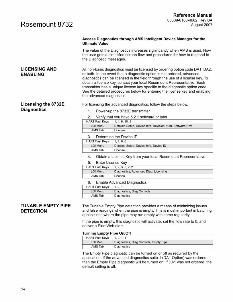
Reference Manual00809-0100-4662, Rev BA
August 2007Rosemount 8732
Access Diagnostics through AMS Intelligent Device Manager for the Ultimate Value
The value of the Diagnostics increases significantly when AMS is used. Now the user gets a simplified screen flow and procedures for how to respond to the Diagnostic messages.
LICENSING AND ENABLING
All non-basic diagnostics must be licensed by ordering option code DA1, DA2, or both. In the event that a diagnostic option is not ordered, advanced diagnostics can be licensed in the field through the use of a license key. To obtain a license key, contact your local Rosemount Representative. Each transmitter has a unique license key specific to the diagnostic option code. See the detailed procedures below for entering the license key and enabling the advanced diagnostics.
Licensing the 8732E Diagnostics
For licensing the advanced diagnostics, follow the steps below.
1. Power-up the 8732E transmitter
2. Verify that you have 5.2.1 software or later
3. Determine the Device ID
4. Obtain a License Key from your local Rosemount Representative.
5. Enter License Key
6. Enable Advanced Diagnostics
TUNABLE EMPTY PIPE DETECTION
The Tunable Empty Pipe detection provides a means of minimizing issues and false readings when the pipe is empty. This is most important in batching applications where the pipe may run empty with some regularity.
If the pipe is empty, this diagnostic will activate, set the flow rate to 0, and deliver a PlantWeb alert.
Turning Empty Pipe On/Off
The Empty Pipe diagnostic can be turned on or off as required by the application. If the advanced diagnostics suite 1 (DA1 Option) was ordered, then the Empty Pipe diagnostic will be turned on. If DA1 was not ordered, the default setting is off.
HART Fast Keys 1, 4, 6, 10, 3
LOI Menu Detailed Setup, Device Info, Revision Num, Software Rev
AMS Tab License
HART Fast Keys 1, 4, 6, 6
LOI Menu Detailed Setup, Device Info, Device ID
AMS Tab License
HART Fast Keys 1, 2, 3, 5, 2, 2
LOI Menu Diagnostics, Advanced Diag, Licensing
AMS Tab License
HART Fast Keys 1, 2, 1
LOI Menu Diagnostics, Diag Controls
AMS Tab Diagnostics
HART Fast Keys 1, 2, 1, 1
LOI Menu Diagnostics, Diag Controls, Empty Pipe
AMS Tab Diagnostics
C-2
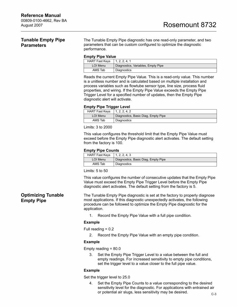
Reference Manual 00809-0100-4662, Rev BA
August 2007 Rosemount 8732
C-3
Tunable Empty Pipe Parameters
The Tunable Empty Pipe diagnostic has one read-only parameter, and two parameters that can be custom configured to optimize the diagnostic performance.
Empty Pipe Value
Reads the current Empty Pipe Value. This is a read-only value. This number is a unitless number and is calculated based on multiple installation and process variables such as flowtube sensor type, line size, process fluid properties, and wiring. If the Empty Pipe Value exceeds the Empty Pipe Trigger Level for a specified number of updates, then the Empty Pipe diagnostic alert will activate.
Empty Pipe Trigger Level
Limits: 3 to 2000
This value configures the threshold limit that the Empty Pipe Value must exceed before the Empty Pipe diagnostic alert activates. The default setting from the factory is 100.
Empty Pipe Counts
Limits: 5 to 50
This value configures the number of consecutive updates that the Empty Pipe Value must exceed the Empty Pipe Trigger Level before the Empty Pipe diagnostic alert activates. The default setting from the factory is 5.
Optimizing Tunable Empty Pipe
The Tunable Empty Pipe diagnostic is set at the factory to properly diagnose most applications. If this diagnostic unexpectedly activates, the following procedure can be followed to optimize the Empty Pipe diagnostic for the application.
1. Record the Empty Pipe Value with a full pipe condition.
Example
Full reading = 0.2
2. Record the Empty Pipe Value with an empty pipe condition.
Example
Empty reading = 80.0
3. Set the Empty Pipe Trigger Level to a value between the full and empty readings. For increased sensitivity to empty pipe conditions, set the trigger level to a value closer to the full pipe value.
Example
Set the trigger level to 25.0
4. Set the Empty Pipe Counts to a value corresponding to the desired sensitivity level for the diagnostic. For applications with entrained air or potential air slugs, less sensitivity may be desired.
HART Fast Keys 1, 2, 2, 4, 1
LOI Menu Diagnostics, Variables, Empty Pipe
AMS Tab Diagnostics
HART Fast Keys 1, 2, 2, 4, 2
LOI Menu Diagnostics, Basic Diag, Empty Pipe
AMS Tab Diagnostics
HART Fast Keys 1, 2, 2, 4, 3
LOI Menu Diagnostics, Basic Diag, Empty Pipe
AMS Tab Diagnostics
Reference Manual00809-0100-4662, Rev BA
August 2007Rosemount 8732
Example
Set the counts to 10
Troubleshooting Empty Pipe
The following actions can be taken if Empty Pipe detection is unexpected.
1. Verify the flowtube sensor is full.
2. Verify that the flowtube sensor has not been installed with a measurement electrode at the top of the pipe.
3. Decrease the sensitivity by setting the Empty Pipe Trigger Level to a value above the Empty Pipe Value read with a full pipe.
4. Decrease the sensitivity by increasing the Empty Pipe Counts to compensate for process noise. The Empty Pipe Counts is the number of consecutive Empty Pipe Value readings above the Empty Pipe Trigger Level required to set the Empty Pipe diagnostic. The count range is 5-50, with factory default set at 5.
5. Increase process fluid conductivity above 50 microsiemens/cm.
6. Properly connect the wiring between the flowtube sensor and the transmitter. Corresponding terminal block numbers in the flowtube sensor and transmitter must be connected.
7. Perform the flowtube sensor electrical resistance tests. Confirm the resistance reading between coil ground (ground symbol) and coil (1 and 2) is infinity, or open. Confirm the resistance reading between electrode ground (17) and an electrode (18 or 19) is greater than 2 kohms and rises. For more detailed information, consult Table 6-6 on page 6-10.
GROUND/WIRING FAULT DETECTION
The Ground/Wiring Fault Detection diagnostic provides a means of verifying installations are done correctly. If the installation is not wired or grounded properly, this diagnostic will activate and deliver a PlantWeb alert. This diagnostic can also detect if the grounding is lost over-time due to corrosion or another root cause.
Turning Ground/Wiring Fault On/Off
The Ground/Wiring Fault diagnostic can be turned on or off as required by the application. If the advanced diagnostics suite 1 (DA1 Option) was ordered, then the Ground/Wiring Fault diagnostic will be turned on. If DA1 was not ordered or licensed, this diagnostic is not available.
Ground/Wiring Fault Parameters
The Ground/Wiring Fault diagnostic has one read-only parameter. It does not have any configurable parameters.
Line Noise
Reads the current amplitude of the Line Noise. This is a read-only value. This number is a measure of the signal strength at 50/60 Hz. If the Line Noise value exceeds 5 mV, then the Ground/Wiring Fault diagnostic alert will activate.
HART Fast Keys 1, 2, 1, 3
LOI Menu Diagnostics, Diag Controls, Ground/Wiring
AMS Tab Diagnostics
HART Fast Keys 1, 2, 4, 3
LOI Menu Diagnostics, Variables, Line Noise
AMS Tab Diagnostics
C-4
Reference Manual 00809-0100-4662, Rev BA
August 2007 Rosemount 8732
Troubleshooting Ground/Wiring Fault
The transmitter detected high levels of 50/60 Hz noise caused by improper wiring or poor process grounding.
1. Verify that the transmitter is earth grounded.
2. Connect ground rings, grounding electrode, lining protector, or grounding straps. Grounding diagrams can be found in “Grounding” on page 5-12.
3. Verify flowtube sensor is full.
4. Verify wiring between flowtube sensor and transmitter is prepared properly. Shielding should be stripped back less than 1 in. (25 mm).
5. Use separate shielded twisted pairs for wiring between flowtube sensor and transmitter.
6. Properly connect the wiring between the flowtube sensor and the transmitter. Corresponding terminal block numbers in the flowtube sensor and transmitter must be connected.
Ground/Wiring Fault Functionality
The transmitter continuously monitors signal amplitudes over a wide range of frequencies. For the Ground/Wiring Fault diagnostic, the transmitter specifically looks at the signal amplitude at frequencies of 50 Hz and 60 Hz which are the common AC cycle frequencies found throughout the world. If the amplitude of the signal at either of these frequencies exceeds 5 mV, that is an indication that there is a ground or wiring issue and that stray electrical signals are getting into the transmitter. The diagnostic alert will activate indicating that the ground and wiring of the installation should be carefully reviewed.
HIGH PROCESS NOISE DETECTION
The High Process Noise diagnostic detects if there is a process condition causing unstable or noisy readings, but the noise is not real flow variation. One common cause of high process noise is slurry flow, like pulp stock or mining slurries. Other conditions that cause this diagnostic to activate are high levels of chemical reaction or entrained gas in the liquid. If unusual noise or variation is seen, this diagnostic will activate and deliver a PlantWeb alert. If this situation exists and is left without remedy, it will add additional uncertainty and noise to the flow reading.
Turning High Process Noise On/Off
The High Process Noise diagnostic can be turned on or off as required by the application. If the advanced diagnostics suite 1 (DA1 Option) was ordered, then the High Process Noise diagnostic will be turned on. If DA1 was not ordered or licensed, this diagnostic is not available.
HART Fast Keys 1, 2, 1, 2
LOI Menu Diagnostics, Diag Controls, Process Noise
AMS Tab Diagnostics
C-5
Reference Manual00809-0100-4662, Rev BA
August 2007Rosemount 8732
High Process Noise Parameters
The High Process Noise diagnostic has two read-only parameters. It does not have any configurable parameters. This diagnostic requires that flow be present in the pipe.
5 Hz Signal to Noise Ratio
Reads the current value of the signal to noise ratio at the coil drive frequency of 5 Hz. This is a read-only value. This number is a measure of the signal strength at 5 Hz relative to the amount of process noise. If the transmitter is operating in 5 Hz mode, and the signal to noise ratio remains below 25 for one minute, then the High Process Noise diagnostic alert will activate.
37 Hz Signal to Noise Ratio
Reads the current value of the signal to noise ratio at the coil drive frequency of 37 Hz. This is a read-only value. This number is a measure of the signal strength at 37 Hz relative to the amount of process noise. If the transmitter is operating in 37 Hz mode, and the signal to noise ratio remains below 25 for one minute, then the High Process Noise diagnostic alert will activate.
Troubleshooting High Process Noise
The transmitter detected high levels of process noise. If the signal to noise ratio is less than 25 while operating in 5 Hz mode, proceed with the following steps:
1. Increase transmitter coil drive frequency to 37 Hz (refer to “Coil Drive Frequency” on page 4-13) and, if possible, perform Auto Zero function (refer to “Auto Zero” on page 4-12).
2. Verify flowtube is electrically connected to the process with grounding electrode, grounding rings with grounding straps, or lining protector with grounding straps.
3. If possible, redirect chemical additions downstream of the magmeter.
4. Verify process fluid conductivity is above 10 microsiemens/cm.
If the signal to noise ratio is less than 25 while operating in 37 Hz mode, proceed with the following steps:
HART Fast Keys 1, 2, 4, 4
LOI Menu Diagnostics, Variables, 5Hz SNR
AMS Tab Diagnostics
HART Fast Keys 1, 2, 4, 5
LOI Menu Diagnostics, Variables, 37Hz SNR
AMS Tab Diagnostics
C-6
Reference Manual 00809-0100-4662, Rev BA
August 2007 Rosemount 8732
1. Turn on the Digital Signal Processing (DSP) technology and follow the setup procedure (refer to Appendix D: Digital Signal Processing). This will minimize the level of damping in the flow measurement and control loop while also stabilizing the reading to minimize valve actuation.
2. Increase damping to stabilize the signal (refer to “PV Damping” on page 3-11). This will add dead-time to the control loop.
3. Move to a Rosemount High-Signal flowmeter system. This flowmeter will deliver a stable signal by increasing the amplitude of the flow signal by up to ten times to increase the signal to noise ratio. For example if the signal to noise ratio (SNR) of a standard magmeter is 5, the High-Signal would have a SNR of 50 in the same application. The Rosemount High-Signal system is comprised of the 8707 flowtube sensor which has modified coils and magnetics and the 8712H High-Signal transmitter.
NOTEIn applications where very high levels of noise are a concern, it is recommended that a dual-calibrated Rosemount High-Signal 8707 flowtube sensor be used. These flowtube sensors can be calibrated to run at lower coil drive current supplied by the standard Rosemount transmitters, but can also be upgraded by changing to the 8712H High-Signal transmitter.
High Process Noise Functionality
The High Process Noise diagnostic is useful for detecting situations where the process fluid may be causing electrical noise resulting in a poor measurement from the magnetic flow meter. There are three basic types of process noise that can affect the performance of the magnetic flowmeter system.
1/f Noise
This type of noise has higher amplitudes at lower frequencies, but generally degrades over increasing frequencies. Potential sources of 1/f noise include chemical mixing and the general background noise of the plant.
Spike Noise
This type of noise generally results in a high amplitude signal at specific frequencies which can vary depending on the source of the noise. Common sources of spike noise include chemical injections directly upstream of the flowmeter, hydraulic pumps, and slurry flows with low concentrations of particles in the stream. The particles bounce off of the electrode generating a “spike” in the electrode signal. An example of this type of flow stream would be a recycle flow in a paper mill.
White Noise
This type of noise results in a high amplitude signal that is relatively constant over the frequency range. Common sources of white noise include chemical reactions or mixing that occurs as the fluid passes through the flowmeter and high concentration slurry flows where the particulates are constantly passing over the electrode head. An example of this type of flow stream would be a basis weight stream in a paper mill.
C-7
Reference Manual00809-0100-4662, Rev BA
August 2007Rosemount 8732
The transmitter continuously monitors signal amplitudes over a wide range of frequencies. For the high process noise diagnostic, the transmitter specifically looks at the signal amplitude at frequencies of 2.5 Hz, 7.5 Hz, 32.5 Hz, and 42.5 Hz. The transmitter uses the values from 2.5 and 7.5 Hz and calculates an average noise level. This average is compared to the amplitude of the signal at 5 Hz. If the signal amplitude is not 25 times greater than the noise level, and the coil drive frequency is set at 5 Hz, the High Process Noise diagnostic will trip indicating that the flow signal may be compromised. The transmitter performs the same analysis around the 37.5 Hz coil drive frequency using the 32.5 Hz and 42.5 Hz values to establish a noise level.
4-20 MA LOOP VERIFICATION
The 4-20 mA Loop Verification diagnostic provides a means of verifying the analog output loop is functioning properly. This is a manually initiated diagnostic test. This diagnostic checks the integrity of the analog loop and provides a health status of the circuit. If the verification does not pass, this will be highlighted in the results given at the end of the check.
Initiating 4-20 mA Loop Verification
The 4-20 mA Loop Verification diagnostic can be initiated as required by the application. If the advanced diagnostics suite 2 (DA2 Option) was ordered, then the 4-20 mA Loop Verification diagnostic will be available. If DA2 was not ordered or licensed, this diagnostic is not available.
4-20 mA Loop Verification Parameters
The 4-20 mA Loop Verification diagnostic has one read-only parameter. It does not have any configurable parameters.
4-20 mA Loop Verification Test Result
Shows the results of the 4-20 mA Loop Verification test as either passed or failed.
Troubleshooting 4-20 mA Loop Verification
The following steps should be followed to identify the cause of the diagnostic failure.
• Check analog loop wiring
• Perform a manual loop test
• Check internal/external power
• Perform D/A Trim
• Check loop resistance
• Replace electronics
HART Fast Keys 1, 2, 3, 4, 1
LOI Menu Diagnostics, Advanced Diag, 4-20 mA Verify, 4-20 mA Verify
AMS Context Menu, Diagnostics and Tests, Analog Output Verification
HART Fast Keys 1, 2, 3, 4, 2
LOI Menu Diagnostics, Advanced Diag, 4-20 mA Verify, View Results
AMS
C-8
Reference Manual 00809-0100-4662, Rev BA
August 2007 Rosemount 8732
C-9
4-20 mA Loop Verification Functionality
The 4-20 mA Loop Verification diagnostic is useful for testing the analog output when errors are suspected. The diagnostic tests the analog loop at 5 points:
• 4 mA
• 12 mA
• 20 mA
• Low alarm level
• High alarm level
8714I CALIBRATION VERIFICATION
The 8714i Calibration Verification diagnostic provides a means of verifying the flowmeter is within calibration without removing the flowtube sensor from the process. This is a manually initiated diagnostic test that provides a review of the transmitter and flowtube sensors critical parameters as a means to document verification of calibration. The results of running this diagnostic provide the deviation amount from expected values and a pass/fail summary against user-defined criteria for the application and conditions.
Initiating 8714i Calibration Verification
The 8714i Calibration Verification diagnostic can be initiated as required by the application. If the advanced diagnostic suite (DA2) was ordered, then the 8714i Calibration Verification diagnostic will be available. If DA2 was not ordered or licensed, this diagnostic will not be available.
Flowtube Sensor Signature Parameters
The flowtube sensor signature describes the magnetic behavior of the sensor. Based on Faraday’s law, the induced voltage measured on the electrodes is proportional to the magnetic field strength. Thus, any changes in the magnetic field will result in a calibration shift of the flowtube sensor.
Establishing the baseline flowtube sensor signature
The first step in running the 8714i Calibration Verification test is establishing the reference signature that the test will use as the baseline for comparison. This is accomplished by having the transmitter take a signature of the flowtube sensor.
Having the transmitter take an initial flowtube sensor signature when first installed will provide the baseline for the verification tests that are done in the future. The flowtube sensor signature should be taken during the start-up process when the transmitter is first connected to the flowtube sensor, with a full line, and ideally with no flow in the line. Running the flowtube sensor signature procedure when there is flow in the line is permissible, but this may introduce some noise into the signature measurements. If an empty pipe condition exists, then the flowtube sensor signature should only be run for the coils.
Once the flowtube sensor signature process is complete, the measurements taken during this procedure are stored in non-volatile memory to prevent loss in the event of a power interruption to the meter.
HART Fast Keys 1, 2, 3, 3, 1
LOI Menu Diagnostics, Advanced Diag, 8714i, Run 8714i
AMS Tab Context Menu, Diagnostics and Tests, 8714i Calibration Verification
HART Fast Keys 1, 2, 3, 3, 3, 2
LOI Menu Diagnostics, Advanced Diag, 8714i, Tube Signature, Re-Signature
AMS Tab Context Menu, Diagnostics and Tests,
Reference Manual00809-0100-4662, Rev BA
August 2007Rosemount 8732
8714i Calibration Verification Test Parameters
The 8714i has a multitude of parameters that set the test criteria, test conditions, and scope of the calibration verification test.
Test Conditions for the 8714i Calibration Verification
There are three possible test conditions that the 8714i Calibration Verification test can be initiated under. This parameter is set at the time that the Flowtube Sensor Signature or 8714i Calibration Verification test is initiated.
No Flow
Run the 8714i Calibration Verification test with a full pipe and no flow in the line. Running the 8714i Calibration Verification test under this condition provides the most accurate results and the best indication of magnetic flowmeter health.
Flowing, Full
Run the 8714i Calibration Verification test with a full pipe and flow in the line. Running the 8714i Calibration Verification test under this condition provides the ability to verify the magnetic flowmeter health without shutting down the process flow in applications where a shutdown is not possible. Running the calibration verification under flowing conditions can cause false fails if the flow rate is not at a steady flow, or if there is process noise present.
Empty Pipe
Run the 8714i Calibration Verification test with an empty pipe. Running the 8714i Calibration Verification test under this condition provides the ability to verify the magnetic flowmeter health with an empty pipe. Running the calibration verification under empty pipe conditions will not check the electrode circuit health.
8714i Calibration Verification Test Criteria
The 8714i Calibration Verification diagnostic provides the ability for the user to define the test criteria that the verification must test to. The test criteria can be set for each of the flow conditions discussed above.
No Flow
Set the test criteria for the No Flow condition. The factory default for this value is set to two percent with limits configurable between one and ten percent.
Flowing, Full
Set the test criteria for the Flowing, Full condition. The factory default for this value is set to three percent with limits configurable between one and ten percent.
HART Fast Keys 1, 2, 3, 3, 4
LOI Menu Diagnostics, Advanced Diag, 8714i, Test Criteria
AMS Tab 8714i
HART Fast Keys 1, 2, 3, 3, 4, 1
LOI Menu Diagnostics, Advanced Diag, 8714i, Test Criteria, No Flow
AMS Tab 8714i
HART Fast Keys 1, 2, 3, 3, 4, 2
LOI Menu Diagnostics, Advanced Diag, 8714i, Test Criteria, Flowing Full
AMS Tab 8714i
C-10
Reference Manual 00809-0100-4662, Rev BA
August 2007 Rosemount 8732
Empty Pipe
Set the test criteria for the Empty Pipe condition. The factory default for this value is set to three percent with limits configurable between one and ten percent.
8714i Calibration Verification Test Scope
The 8714i Calibration Verification can be used to verify the entire flowmeter installation, or individual parts such as the transmitter or flowtube sensor. This parameter is set at the time that the 8714i Calibration Verification test is initiated.
All
Run the 8714i Calibration Verification test and verify the entire flowmeter installation. This parameter results in the calibration verification performing the transmitter calibration verification, tube calibration verification, coil health check, and electrode health check. Transmitter calibration and tube calibration are verified to the percentage associated with the test condition selected when the test was initiated.
Transmitter
Run the 8714i Calibration Verification test on the transmitter only. This results in the verification test only checking the transmitter calibration to the limits of the test criteria selected when the 8714i Calibration Verification test was initiated.
Flowtube Sensor
Run the 8714i Calibration Verification test on the flowtube sensor only. This results in the verification test checking the flowtube sensor calibration to the limits of the test criteria selected when the 8714i Calibration Verification test was initiated, verifying the coil circuit health, and the electrode circuit health.
8714i Calibration Verification Test Results Parameters
Once the 8714i Calibration Verification test is initiated, the transmitter will make several measurements to verify the transmitter calibration, tube calibration, coil circuit health, and electrode circuit health. The results of these tests can be reviewed and recorded on the calibration verification report found on page C-17. This report can be used to validate that the meter is within the required calibration limits to comply with governmental regulatory agencies such as the Environmental Protection Agency or Food and Drug Administration.
HART Fast Keys 1, 2, 3, 3, 4, 3
LOI Menu Diagnostics, Advanced Diag, 8714i, Test Criteria, Empty Pipe
AMS Tab 8714i
HART Fast Keys 1, 2, 3, 3, 1, 1
LOI Menu Diagnostics, Advanced Diag, 8714i, Run 8714i
AMS Context Menu, Diagnostics and Tests, 8714i Calibration Verification
HART Fast Keys 1, 2, 3, 3, 1, 2
LOI Menu Diagnostics, Advanced Diag, 8714i, Run 8714i
AMS Context Menu, Diagnostics and Tests, 8714i Calibration Verification
HART Fast Keys 1, 2, 3, 3, 1, 3
LOI Menu Diagnostics, Advanced Diag, 8714i, Run 8714i
AMS Context Menu, Diagnostics and Tests, 8714i Calibration Verification
C-11
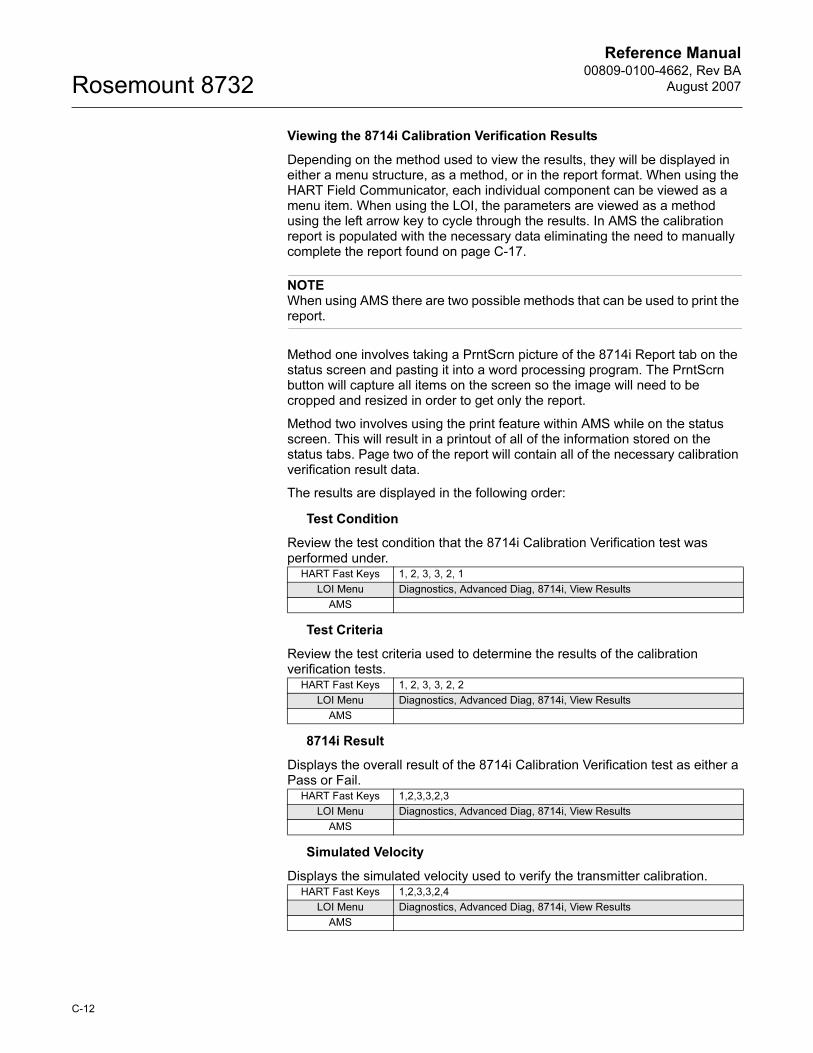
Reference Manual00809-0100-4662, Rev BA
August 2007Rosemount 8732
Viewing the 8714i Calibration Verification Results
Depending on the method used to view the results, they will be displayed in either a menu structure, as a method, or in the report format. When using the HART Field Communicator, each individual component can be viewed as a menu item. When using the LOI, the parameters are viewed as a method using the left arrow key to cycle through the results. In AMS the calibration report is populated with the necessary data eliminating the need to manually complete the report found on page C-17.
NOTE When using AMS there are two possible methods that can be used to print the report.
Method one involves taking a PrntScrn picture of the 8714i Report tab on the status screen and pasting it into a word processing program. The PrntScrn button will capture all items on the screen so the image will need to be cropped and resized in order to get only the report.
Method two involves using the print feature within AMS while on the status screen. This will result in a printout of all of the information stored on the status tabs. Page two of the report will contain all of the necessary calibration verification result data.
The results are displayed in the following order:
Test Condition
Review the test condition that the 8714i Calibration Verification test was performed under.
Test Criteria
Review the test criteria used to determine the results of the calibration verification tests.
8714i Result
Displays the overall result of the 8714i Calibration Verification test as either a Pass or Fail.
Simulated Velocity
Displays the simulated velocity used to verify the transmitter calibration.
HART Fast Keys 1, 2, 3, 3, 2, 1
LOI Menu Diagnostics, Advanced Diag, 8714i, View Results
AMS
HART Fast Keys 1, 2, 3, 3, 2, 2
LOI Menu Diagnostics, Advanced Diag, 8714i, View Results
AMS
HART Fast Keys 1,2,3,3,2,3
LOI Menu Diagnostics, Advanced Diag, 8714i, View Results
AMS
HART Fast Keys 1,2,3,3,2,4
LOI Menu Diagnostics, Advanced Diag, 8714i, View Results
AMS
C-12
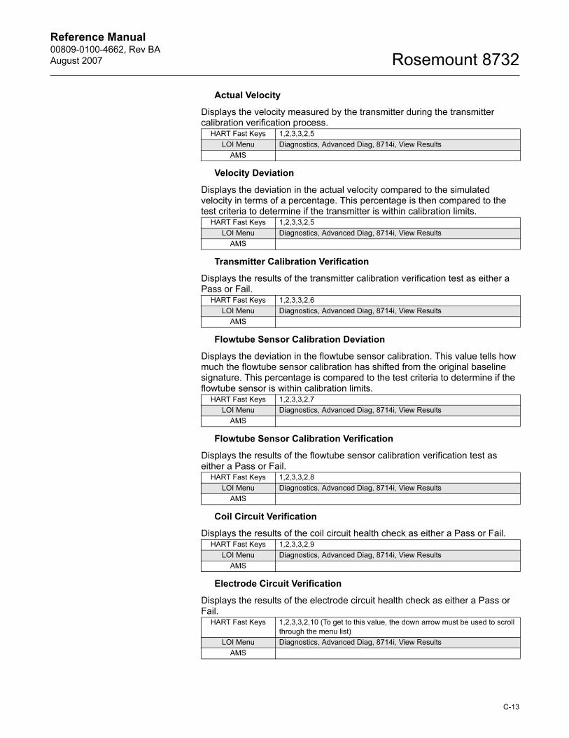
Reference Manual 00809-0100-4662, Rev BA
August 2007 Rosemount 8732
Actual Velocity
Displays the velocity measured by the transmitter during the transmitter calibration verification process.
Velocity Deviation
Displays the deviation in the actual velocity compared to the simulated velocity in terms of a percentage. This percentage is then compared to the test criteria to determine if the transmitter is within calibration limits.
Transmitter Calibration Verification
Displays the results of the transmitter calibration verification test as either a Pass or Fail.
Flowtube Sensor Calibration Deviation
Displays the deviation in the flowtube sensor calibration. This value tells how much the flowtube sensor calibration has shifted from the original baseline signature. This percentage is compared to the test criteria to determine if the flowtube sensor is within calibration limits.
Flowtube Sensor Calibration Verification
Displays the results of the flowtube sensor calibration verification test as either a Pass or Fail.
Coil Circuit Verification
Displays the results of the coil circuit health check as either a Pass or Fail.
Electrode Circuit Verification
Displays the results of the electrode circuit health check as either a Pass or Fail.
HART Fast Keys 1,2,3,3,2,5
LOI Menu Diagnostics, Advanced Diag, 8714i, View Results
AMS
HART Fast Keys 1,2,3,3,2,5
LOI Menu Diagnostics, Advanced Diag, 8714i, View Results
AMS
HART Fast Keys 1,2,3,3,2,6
LOI Menu Diagnostics, Advanced Diag, 8714i, View Results
AMS
HART Fast Keys 1,2,3,3,2,7
LOI Menu Diagnostics, Advanced Diag, 8714i, View Results
AMS
HART Fast Keys 1,2,3,3,2,8
LOI Menu Diagnostics, Advanced Diag, 8714i, View Results
AMS
HART Fast Keys 1,2,3,3,2,9
LOI Menu Diagnostics, Advanced Diag, 8714i, View Results
AMS
HART Fast Keys 1,2,3,3,2,10 (To get to this value, the down arrow must be used to scroll
through the menu list)
LOI Menu Diagnostics, Advanced Diag, 8714i, View Results
AMS
C-13
Reference Manual00809-0100-4662, Rev BA
August 2007Rosemount 8732
Optimizing the 8714i Calibration Verification
The 8714i Calibration Verification diagnostic can be optimized by setting the test criteria to the desired levels necessary to meet the compliance requirements of the application. The following examples below will provide some guidance on how to set these levels.
Example
An effluent meter must be certified every year to comply with Environmental Protection Agency and Pollution Control Agency standards. These governmental agencies require that the meter be certified to five percent accuracy.
Since this is an effluent meter, shutting down the process may not be viable. In this instance the 8714i Calibration Verification test will be performed under flowing conditions. Set the test criteria for Flowing, Full to five percent to meet the requirements of the governmental agencies.
Example
A pharmaceutical company requires bi-annual verification of meter calibration on a critical feed line for one of their products. This is an internal standard, but plant requirements require a calibration record be kept on-hand. Meter calibration on this process must meet one percent. The process is a batch process so it is possible to perform the calibration verification with the line full and with no flow.
Since the 8714i Calibration Verification test can be run under no flow conditions, set the test criteria for No Flow to one percent to comply with the necessary plant standards.
Example
A food and beverage company requires an annual calibration of a meter on a product line. The plant standard calls for the accuracy to be three percent or better. They manufacture this product in batches, and the measurement cannot be interrupted when a batch is in process. When the batch is complete, the line goes empty.
Since there is no means of performing the 8714i Calibration Verification test while there is product in the line, the test must be performed under empty pipe conditions. The test criteria for Empty Pipe should be set to three percent, and it should be noted that the electrode circuit health cannot be verified.
C-14
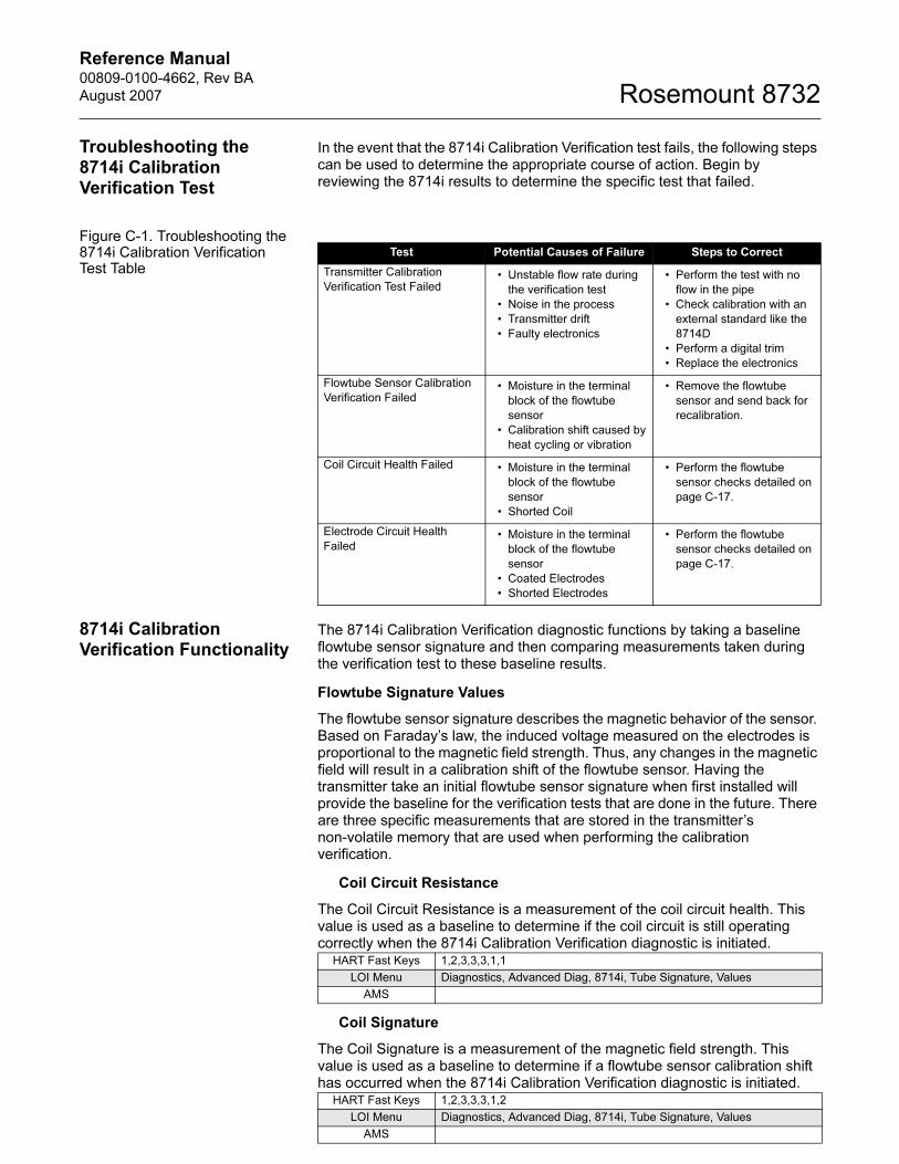
Reference Manual 00809-0100-4662, Rev BA
August 2007 Rosemount 8732
C-15
Troubleshooting the 8714i Calibration Verification Test
In the event that the 8714i Calibration Verification test fails, the following steps can be used to determine the appropriate course of action. Begin by reviewing the 8714i results to determine the specific test that failed.
Figure C-1. Troubleshooting the 8714i Calibration Verification Test Table
8714i Calibration Verification Functionality
The 8714i Calibration Verification diagnostic functions by taking a baseline flowtube sensor signature and then comparing measurements taken during the verification test to these baseline results.
Flowtube Signature Values
The flowtube sensor signature describes the magnetic behavior of the sensor. Based on Faraday’s law, the induced voltage measured on the electrodes is proportional to the magnetic field strength. Thus, any changes in the magnetic field will result in a calibration shift of the flowtube sensor. Having the transmitter take an initial flowtube sensor signature when first installed will provide the baseline for the verification tests that are done in the future. There are three specific measurements that are stored in the transmitter’s non-volatile memory that are used when performing the calibration verification.
Coil Circuit Resistance
The Coil Circuit Resistance is a measurement of the coil circuit health. This value is used as a baseline to determine if the coil circuit is still operating correctly when the 8714i Calibration Verification diagnostic is initiated.
Coil Signature
The Coil Signature is a measurement of the magnetic field strength. This value is used as a baseline to determine if a flowtube sensor calibration shift has occurred when the 8714i Calibration Verification diagnostic is initiated.
Test Potential Causes of Failure Steps to Correct
Transmitter Calibration
Verification Test Failed• Unstable flow rate during
the verification test
• Noise in the process
• Transmitter drift
• Faulty electronics
• Perform the test with no
flow in the pipe
• Check calibration with an
external standard like the
8714D
• Perform a digital trim
• Replace the electronics
Flowtube Sensor Calibration
Verification Failed• Moisture in the terminal
block of the flowtube
sensor
• Calibration shift caused by
heat cycling or vibration
• Remove the flowtube
sensor and send back for
recalibration.
Coil Circuit Health Failed • Moisture in the terminal
block of the flowtube
sensor
• Shorted Coil
• Perform the flowtube
sensor checks detailed on
page C-17.
Electrode Circuit Health
Failed• Moisture in the terminal
block of the flowtube
sensor
• Coated Electrodes
• Shorted Electrodes
• Perform the flowtube
sensor checks detailed on
page C-17.
HART Fast Keys 1,2,3,3,3,1,1
LOI Menu Diagnostics, Advanced Diag, 8714i, Tube Signature, Values
AMS
HART Fast Keys 1,2,3,3,3,1,2
LOI Menu Diagnostics, Advanced Diag, 8714i, Tube Signature, Values
AMS
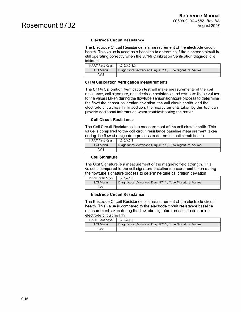
Reference Manual00809-0100-4662, Rev BA
August 2007Rosemount 8732
Electrode Circuit Resistance
The Electrode Circuit Resistance is a measurement of the electrode circuit health. This value is used as a baseline to determine if the electrode circuit is still operating correctly when the 8714i Calibration Verification diagnostic is initiated.
8714i Calibration Verification Measurements
The 8714i Calibration Verification test will make measurements of the coil resistance, coil signature, and electrode resistance and compare these values to the values taken during the flowtube sensor signature process to determine the flowtube sensor calibration deviation, the coil circuit health, and the electrode circuit health. In addition, the measurements taken by this test can provide additional information when troubleshooting the meter.
Coil Circuit Resistance
The Coil Circuit Resistance is a measurement of the coil circuit health. This value is compared to the coil circuit resistance baseline measurement taken during the flowtube signature process to determine coil circuit health.
Coil Signature
The Coil Signature is a measurement of the magnetic field strength. This value is compared to the coil signature baseline measurement taken during the flowtube signature process to determine tube calibration deviation.
Electrode Circuit Resistance
The Electrode Circuit Resistance is a measurement of the electrode circuit health. This value is compared to the electrode circuit resistance baseline measurement taken during the flowtube signature process to determine electrode circuit health.
HART Fast Keys 1,2,3,3,3,1,3
LOI Menu Diagnostics, Advanced Diag, 8714i, Tube Signature, Values
AMS
HART Fast Keys 1,2,3,3,5,1
LOI Menu Diagnostics, Advanced Diag, 8714i, Tube Signature, Values
AMS
HART Fast Keys 1,2,3,3,5,2
LOI Menu Diagnostics, Advanced Diag, 8714i, Tube Signature, Values
AMS
HART Fast Keys 1,2,3,3,5,3
LOI Menu Diagnostics, Advanced Diag, 8714i, Tube Signature, Values
AMS
C-16
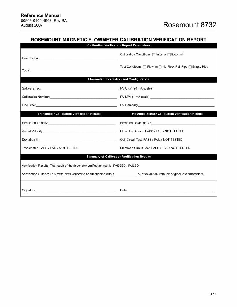
Reference Manual 00809-0100-4662, Rev BA
August 2007 Rosemount 8732
ROSEMOUNT MAGNETIC FLOWMETER CALIBRATION VERIFICATION REPORTCalibration Verification Report Parameters
User Name: _____________________________________________
Calibration Conditions: □ Internal □ External
Tag #:__________________________________________________
Test Conditions: □ Flowing □ No Flow, Full Pipe □ Empty Pipe
Flowmeter Information and Configuration
Software Tag:____________________________________________ PV URV (20 mA scale):____________________________________
Calibration Number:_______________________________________ PV LRV (4 mA scale):_____________________________________
Line Size:_______________________________________________ PV Damping:____________________________________________
Transmitter Calibration Verification Results Flowtube Sensor Calibration Verification Results
Simulated Velocity:_______________________________________ Flowtube Deviation %:_____________________________________
Actual Velocity:__________________________________________ Flowtube Sensor: PASS / FAIL / NOT TESTED
Deviation %:____________________________________________ Coil Circuit Test: PASS / FAIL / NOT TESTED
Transmitter: PASS / FAIL / NOT TESTED Electrode Circuit Test: PASS / FAIL / NOT TESTED
Summary of Calibration Verification Results
Verification Results: The result of the flowmeter verification test is: PASSED / FAILED
Verification Criteria: This meter was verified to be functioning within _____________ % of deviation from the original test parameters.
Signature:______________________________________________ Date:__________________________________________________
C-17

Reference Manual00809-0100-4662, Rev BA
August 2007Rosemount 8732
C-18
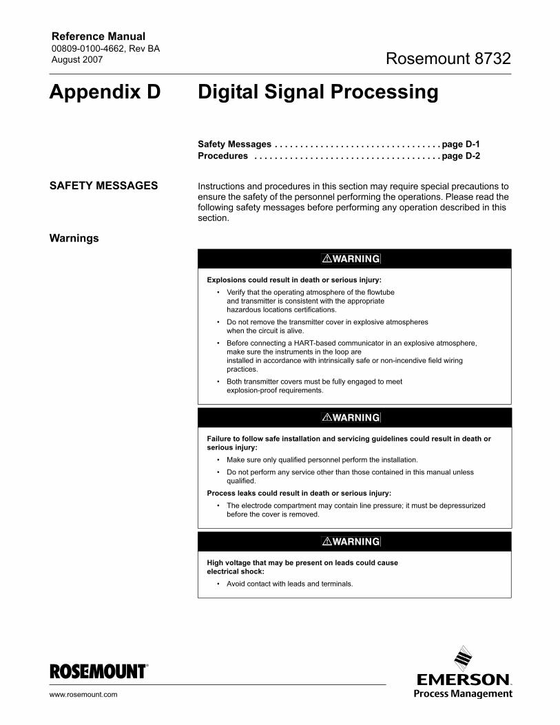
Reference Manual 00809-0100-4662, Rev BA
August 2007 Rosemount 8732
Appendix D Digital Signal Processing
Safety Messages . . . . . . . . . . . . . . . . . . . . . . . . . . . . . . . . . page D-1
Procedures . . . . . . . . . . . . . . . . . . . . . . . . . . . . . . . . . . . . . page D-2
SAFETY MESSAGES Instructions and procedures in this section may require special precautions to ensure the safety of the personnel performing the operations. Please read the following safety messages before performing any operation described in this section.
Warnings
Explosions could result in death or serious injury:
• Verify that the operating atmosphere of the flowtube
and transmitter is consistent with the appropriate
hazardous locations certifications.
• Do not remove the transmitter cover in explosive atmospheres
when the circuit is alive.
• Before connecting a HART-based communicator in an explosive atmosphere,
make sure the instruments in the loop are
installed in accordance with intrinsically safe or non-incendive field wiring
practices.
• Both transmitter covers must be fully engaged to meet
explosion-proof requirements.
Failure to follow safe installation and servicing guidelines could result in death or serious injury:
• Make sure only qualified personnel perform the installation.
• Do not perform any service other than those contained in this manual unless
qualified.
Process leaks could result in death or serious injury:
• The electrode compartment may contain line pressure; it must be depressurized
before the cover is removed.
High voltage that may be present on leads could cause electrical shock:
• Avoid contact with leads and terminals.
www.rosemount.com
Reference Manual00809-0100-4662, Rev BA
August 2007Rosemount 8732
PROCEDURES If the output of your Rosemount 8732E is unstable, first check the wiring and grounding associated with the magnetic flowmeter system. Ensure that the following conditions are met:
• Ground straps are attached to the adjacent flange or ground ring?
• Grounding rings, lining protectors, or grounding electrodes are being used in lined or nonconductive piping?
• Both of the shields attached at both ends?
The causes of unstable transmitter output can usually be traced to extraneous voltages on the measuring electrodes. This “process noise” can arise from several causes including electrochemical reactions between the fluid and the electrode, chemical reactions in the process itself, free ion activity in the fluid, or some other disturbance of the fluid/electrode capacitive layer. In such noisy applications, an analysis of the frequency spectrum reveals process noise that typically becomes significant below 15 Hz.
In some cases, the effects of process noise may be sharply reduced by elevating the coil drive frequency above the 15 Hz region. The Rosemount 8732E coil drive mode is selectable between the standard 5 Hz and the noise-reducing 37 Hz. See “Coil Drive Frequency” on page 3-15 for instructions on how to change the coil drive mode to 37 Hz.
Auto Zero To ensure optimum accuracy when using 37 Hz coil drive mode, there is an auto zero function that must be initiated during start-up. The auto zero operation is also discussed in the start-up and configuration sections. When using 37 Hz coil drive mode it is important to zero the system for the specific application and installation.
The auto zero procedure should be performed only under the following conditions:
• With the transmitter and flowtube installed in their final positions. This procedure is not applicable on the bench.
• With the transmitter in 37 Hz coil drive mode. Never attempt this procedure with the transmitter in 5 Hz coil drive mode.
• With the flowtube full of process fluid at zero flow.
These conditions should cause an output equivalent to zero flow.
Signal Processing If the 37 Hz coil drive mode has been set, and the output is still unstable, the damping and signal processing function should be used. It is important to set the coil drive mode to 37 Hz first, so the loop response time is not increased.
The 8732E provides for a very easy and straightforward start-up, and also incorporates the capability to deal with difficult applications that have previously manifested themselves in a noisy output signal. In addition to selecting a higher coil drive frequency (37 Hz vs. 5 Hz) to isolate the flow signal from the process noise, the 8732E microprocessor can actually scrutinize each input based on three user-defined parameters to reject the noise specific to the application.
D-2
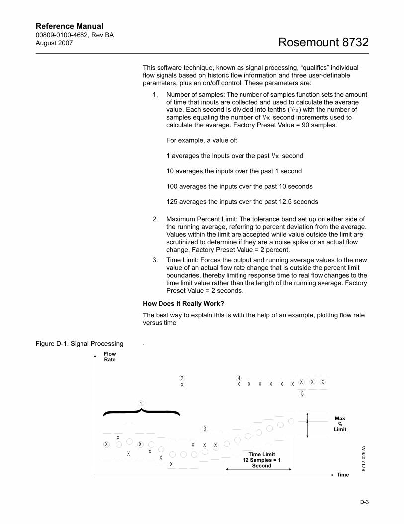
Reference Manual 00809-0100-4662, Rev BA
August 2007 Rosemount 8732
This software technique, known as signal processing, “qualifies” individual flow signals based on historic flow information and three user-definable parameters, plus an on/off control. These parameters are:
1. Number of samples: The number of samples function sets the amount of time that inputs are collected and used to calculate the average
value. Each second is divided into tenths (1/10 ) with the number of
samples equaling the number of 1/10 second increments used to calculate the average. Factory Preset Value = 90 samples.
For example, a value of:
1 averages the inputs over the past 1/10 second
10 averages the inputs over the past 1 second
100 averages the inputs over the past 10 seconds
125 averages the inputs over the past 12.5 seconds
2. Maximum Percent Limit: The tolerance band set up on either side of the running average, referring to percent deviation from the average. Values within the limit are accepted while value outside the limit are scrutinized to determine if they are a noise spike or an actual flow change. Factory Preset Value = 2 percent.
3. Time Limit: Forces the output and running average values to the new value of an actual flow rate change that is outside the percent limit boundaries, thereby limiting response time to real flow changes to the time limit value rather than the length of the running average. Factory Preset Value = 2 seconds.
How Does It Really Work?
The best way to explain this is with the help of an example, plotting flow rate versus time
Figure D-1. Signal Processing .
8712-0292A
FlowRate
Max%
Limit
Time Limit12 Samples = 1
Second
Time
D-3
Reference Manual00809-0100-4662, Rev BA
August 2007Rosemount 8732
x: Input flow signal from flowtube.
o: Average flow signals and transmitter output, determined by the “number
of samples” parameter.
Tolerance band, determined by the “percent limit” parameter.
– Upper value = average flow + [(percent limit/100) average flow]
– Lower value = average flow – [(percent limit/100) average flow]
� This scenario is that of a typical non-noisy flow. The input flow signal is
within the percent limit tolerance band, therefore qualifying itself as a
good input. In this case the new input is
added directly into the running average and is passed on as a part of the
average value to the output.
� This signal is outside the tolerance band and therefore is held in memory
until the next input can be evaluated. The running average is provided as
the output.
� The previous signal currently held in memory is simply rejected
as a noise spike since the next flow input signal is back within the
tolerance band. This results in complete rejection of noise spikes rather
than allowing them to be “averaged” with the good signals as occurs in
the typical analog damping circuits.
� As in Number �above, the input is outside the tolerance band.
This first signal is held in memory and compared to the next signal. The
next signal is also outside the tolerance band (in the same direction), so
the stored value is added to the running average as the next input and
the running average begins to slowly approach the new input level.
� To avoid waiting for the slowly incrementing average value to catch up to
the new level input, a shortcut is provided. This is the “time limit”
parameter. The user can set this parameter to eliminate the slow
ramping of the output toward the new input level.
When Should Signal Processing Be Used?
The Rosemount 8732E offers three separate functions that can be used in series for improving a noisy output. The first step is to toggle the coil drive to the 37 Hz mode and initialize with an auto zero. If the output is still noisy at this stage, signal processing should be actuated and, if necessary, tuned to match the specific application. Finally, if the signal is still too unstable, the traditional damping function can be used.
NOTEFailure to complete an Auto Zero will result in a small (<1%) error in the output. While the output level will be offset by the error, the repeatability will not be affected.
D-4
Reference Manual 00809-0100-4662, Rev BA
August 2007 Rosemount 8732
Appendix E Universal Flowtube Wiring Diagrams
Rosemount Flowtubes . . . . . . . . . . . . . . . . . . . . . . . . . . . . page E-3
Brooks Flowtubes . . . . . . . . . . . . . . . . . . . . . . . . . . . . . . . . page E-6
Perform the Universal Auto Trim function. . . . . . . . . . . . page E-5
Fischer And Porter Flowtubes . . . . . . . . . . . . . . . . . . . . . . page E-8
Foxboro Flowtubes . . . . . . . . . . . . . . . . . . . . . . . . . . . . . . . page E-15
Kent Veriflux VTC Flowtube . . . . . . . . . . . . . . . . . . . . . . . . page E-19
Kent Flowtubes . . . . . . . . . . . . . . . . . . . . . . . . . . . . . . . . . . page E-20
Krohne Flowtubes . . . . . . . . . . . . . . . . . . . . . . . . . . . . . . . page E-21
Taylor Flowtubes . . . . . . . . . . . . . . . . . . . . . . . . . . . . . . . . page E-22
Yamatake Honeywell Flowtubes . . . . . . . . . . . . . . . . . . . . page E-24
Yokogawa Flowtubes . . . . . . . . . . . . . . . . . . . . . . . . . . . . . page E-25
Generic Manufacturer Flowtubes . . . . . . . . . . . . . . . . . . . page E-26
The wiring diagrams in this section illustrate the proper connections between the Rosemount 8732E and most flowtubes currently on the market. Specific diagrams are included for most models, and where information for a particular model of a manufacturer is not available, a generic drawing pertaining to that manufacturers’ flowtubes is provided. If the manufacturer for your flowtube is not included, see the drawing for generic connections.
www.rosemount.com
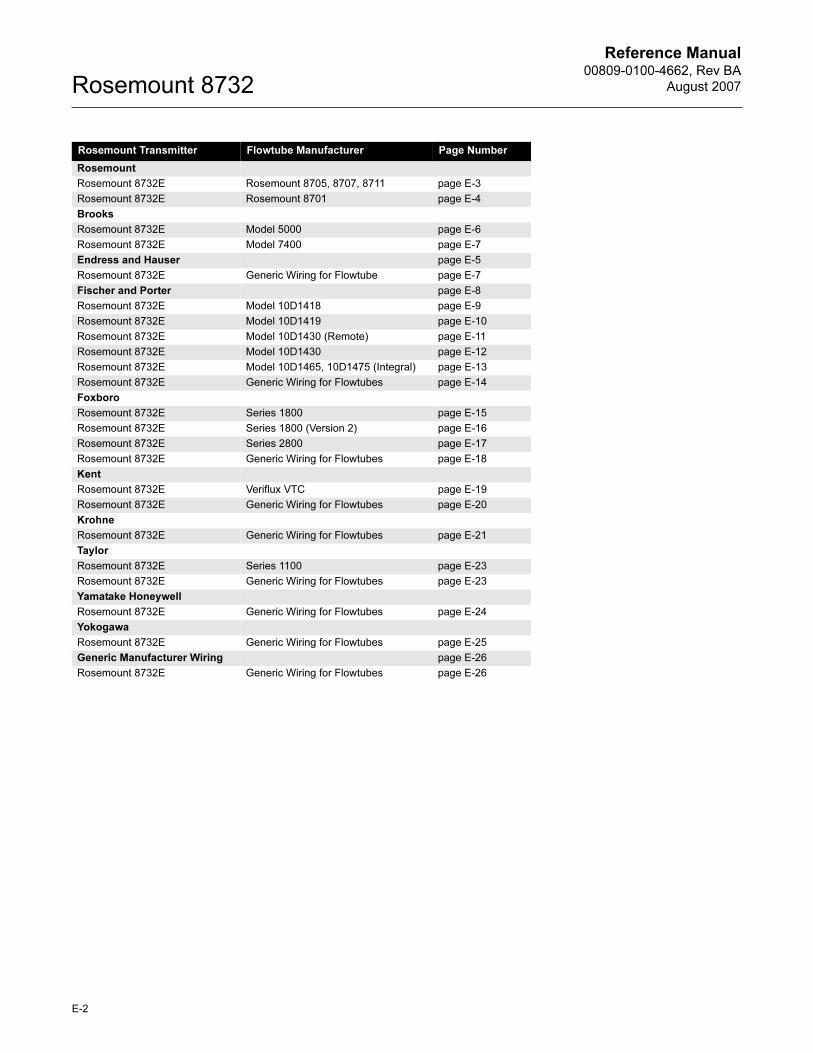
Reference Manual00809-0100-4662, Rev BA
August 2007Rosemount 8732
Rosemount Transmitter Flowtube Manufacturer Page Number
Rosemount
Rosemount 8732E Rosemount 8705, 8707, 8711 page E-3
Rosemount 8732E Rosemount 8701 page E-4
Brooks
Rosemount 8732E Model 5000 page E-6
Rosemount 8732E Model 7400 page E-7
Endress and Hauser page E-5
Rosemount 8732E Generic Wiring for Flowtube page E-7
Fischer and Porter page E-8
Rosemount 8732E Model 10D1418 page E-9
Rosemount 8732E Model 10D1419 page E-10
Rosemount 8732E Model 10D1430 (Remote) page E-11
Rosemount 8732E Model 10D1430 page E-12
Rosemount 8732E Model 10D1465, 10D1475 (Integral) page E-13
Rosemount 8732E Generic Wiring for Flowtubes page E-14
Foxboro
Rosemount 8732E Series 1800 page E-15
Rosemount 8732E Series 1800 (Version 2) page E-16
Rosemount 8732E Series 2800 page E-17
Rosemount 8732E Generic Wiring for Flowtubes page E-18
Kent
Rosemount 8732E Veriflux VTC page E-19
Rosemount 8732E Generic Wiring for Flowtubes page E-20
Krohne
Rosemount 8732E Generic Wiring for Flowtubes page E-21
Taylor
Rosemount 8732E Series 1100 page E-23
Rosemount 8732E Generic Wiring for Flowtubes page E-23
Yamatake Honeywell
Rosemount 8732E Generic Wiring for Flowtubes page E-24
Yokogawa
Rosemount 8732E Generic Wiring for Flowtubes page E-25
Generic Manufacturer Wiring page E-26
Rosemount 8732E Generic Wiring for Flowtubes page E-26
E-2
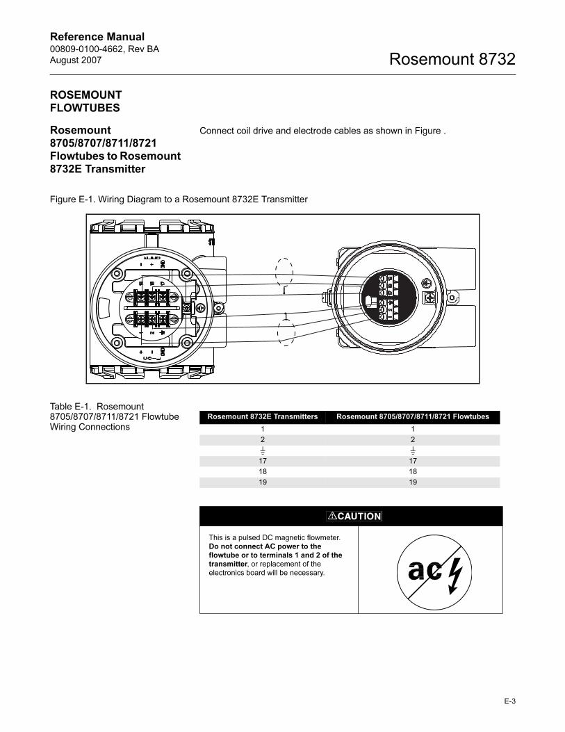
Reference Manual 00809-0100-4662, Rev BA
August 2007 Rosemount 8732
ROSEMOUNT FLOWTUBES
Rosemount 8705/8707/8711/8721 Flowtubes to Rosemount 8732E Transmitter
Connect coil drive and electrode cables as shown in Figure .
Figure E-1. Wiring Diagram to a Rosemount 8732E Transmitter
Table E-1. Rosemount 8705/8707/8711/8721 Flowtube Wiring Connections
Rosemount 8732E Transmitters Rosemount 8705/8707/8711/8721 Flowtubes
1 1
2 2
17 17
18 18
19 19
This is a pulsed DC magnetic flowmeter.
Do not connect AC power to the flowtube or to terminals 1 and 2 of the transmitter, or replacement of the
electronics board will be necessary.
E-3
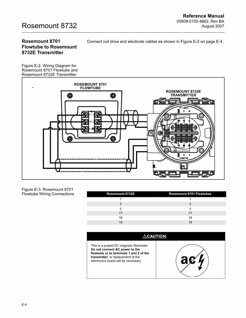
Reference Manual00809-0100-4662, Rev BA
August 2007Rosemount 8732
Rosemount 8701 Flowtube to Rosemount 8732E Transmitter
Connect coil drive and electrode cables as shown in Figure E-2 on page E-4.
Figure E-2. Wiring Diagram for Rosemount 8701 Flowtube and Rosemount 8732E Transmitter
Figure E-3. Rosemount 8701 Flowtube Wiring Connections
2
1
19
18
17
ROSEMOUNT 8701 FLOWTUBE
ROSEMOUNT 8732E TRANSMITTER
Rosemount 8732E Rosemount 8701 Flowtubes
1 1
2 2
17 17
18 18
19 19
This is a pulsed DC magnetic flowmeter.
Do not connect AC power to the flowtube or to terminals 1 and 2 of the transmitter, or replacement of the
electronics board will be necessary.
E-4
Reference Manual 00809-0100-4662, Rev BA
August 2007 Rosemount 8732
Connecting Flowtubes of Other Manufacturers
Before connecting another manufacturer’s flowtube to the Rosemount 8732E transmitter, it is necessary to perform the following functions.
1. Turn off the AC power to the flowtube and transmitter. Failure to do so could result in electrical shock or damage to the transmitter.
2. Verify that the coil drive cables between the flowtube and the transmitter are not connected to any other equipment.
3. Label the coil drive cables and electrode cables for connection to the transmitter.
4. Disconnect the wires from the existing transmitter.
5. Remove the existing transmitter. Mount the new transmitter. See “Mount the Transmitter” on page 2-3.
6. Verify that the flowtube coil is configured for series connection. Other manufacturers flowtubes may be wired in either a series or parallel circuit. All Rosemount magnetic flowtubes are wired in a series circuit. (Other manufacturers AC flowtubes (AC coils) wired for 220V operation are typically wired in parallel and must be rewired in series.)
7. Verify that the flowtube is in good working condition. Use the manufacturer’s recommended test procedure for verification of flowtube condition. Perform the basic checks:
a. Check the coils for shorts or open circuits.
b. Check the flowtube liner for wear or damage.
c. Check the electrodes for shorts, leaks, or damage.
8. Connect the flowtube to the transmitter in accordance with reference wiring diagrams. See Appendix E: Universal Flowtube Wiring Diagrams for specific drawings.
9. Connect and verify all connections between the flowtube and the transmitter, then apply power to the transmitter.
10. Perform the Universal Auto Trim function.
This is a pulsed DC magnetic flowmeter. Do not connect AC power to the flowtube or to terminals 1 and 2 of the transmitter, or replacement of the electronics board will be
necessary.
E-5
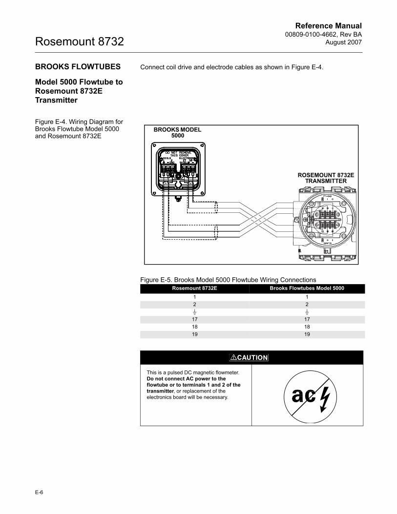
Reference Manual00809-0100-4662, Rev BA
August 2007Rosemount 8732
BROOKS FLOWTUBES Connect coil drive and electrode cables as shown in Figure E-4.
Model 5000 Flowtube to Rosemount 8732E Transmitter
Figure E-4. Wiring Diagram for Brooks Flowtube Model 5000 and Rosemount 8732E
Figure E-5. Brooks Model 5000 Flowtube Wiring Connections
Rosemount 8732E Brooks Flowtubes Model 5000
1 1
2 2
17 17
18 18
19 19
BROOKS MODEL 5000
ROSEMOUNT 8732E TRANSMITTER
This is a pulsed DC magnetic flowmeter.
Do not connect AC power to the flowtube or to terminals 1 and 2 of the transmitter, or replacement of the
electronics board will be necessary.
E-6
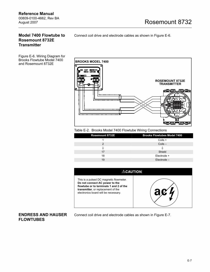
Reference Manual 00809-0100-4662, Rev BA
August 2007 Rosemount 8732
Model 7400 Flowtube to Rosemount 8732E Transmitter
Connect coil drive and electrode cables as shown in Figure E-6.
Figure E-6. Wiring Diagram for Brooks Flowtube Model 7400 and Rosemount 8732E
ENDRESS AND HAUSER FLOWTUBES
Connect coil drive and electrode cables as shown in Figure E-7.
Table E-2. Brooks Model 7400 Flowtube Wiring Connections
Rosemount 8732E Brooks Flowtubes Model 7400
1 Coils +
2 Coils –
17 Shield
18 Electrode +
19 Electrode –
BROOKS MODEL 7400
ROSEMOUNT 8732E TRANSMITTER
This is a pulsed DC magnetic flowmeter.
Do not connect AC power to the flowtube or to terminals 1 and 2 of the transmitter, or replacement of the
electronics board will be necessary.
E-7
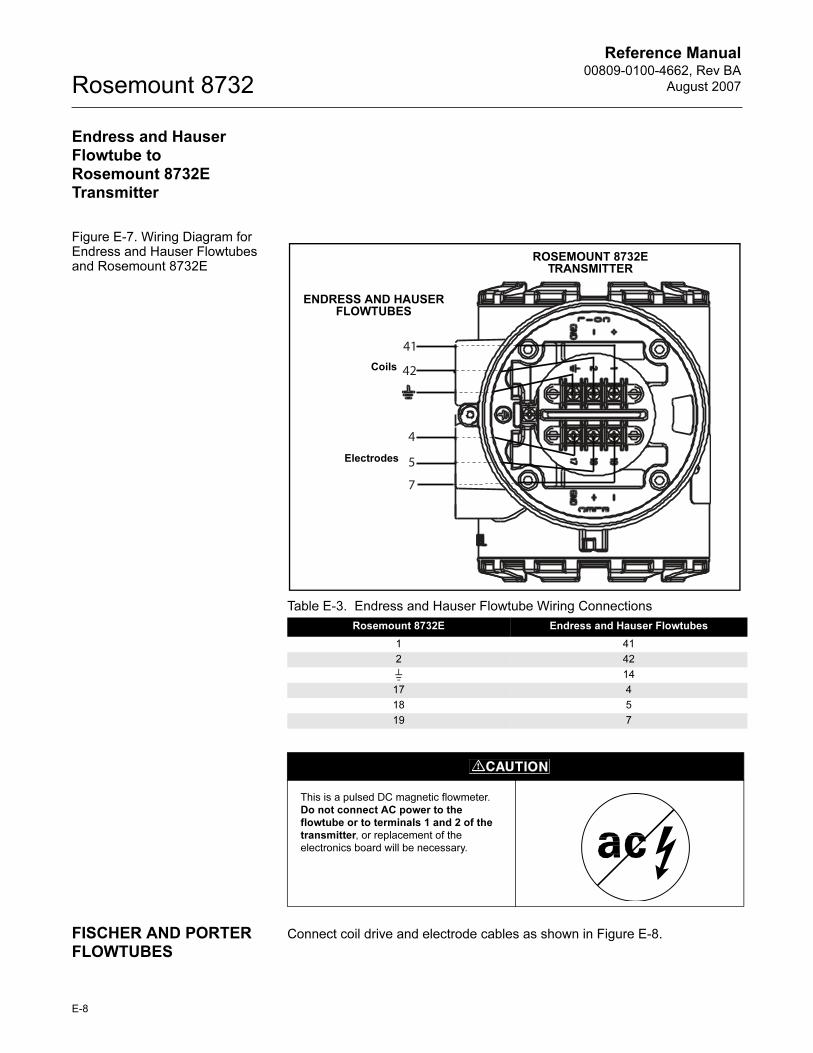
Reference Manual00809-0100-4662, Rev BA
August 2007Rosemount 8732
Endress and Hauser Flowtube to Rosemount 8732E Transmitter
Figure E-7. Wiring Diagram for Endress and Hauser Flowtubes and Rosemount 8732E
FISCHER AND PORTER FLOWTUBES
Connect coil drive and electrode cables as shown in Figure E-8.
Table E-3. Endress and Hauser Flowtube Wiring Connections
Rosemount 8732E Endress and Hauser Flowtubes
1 41
2 42
14
17 4
18 5
19 7
41
42
4
5
7
Electrodes
Coils
ROSEMOUNT 8732E TRANSMITTER
ENDRESS AND HAUSER FLOWTUBES
This is a pulsed DC magnetic flowmeter.
Do not connect AC power to the flowtube or to terminals 1 and 2 of the transmitter, or replacement of the
electronics board will be necessary.
E-8
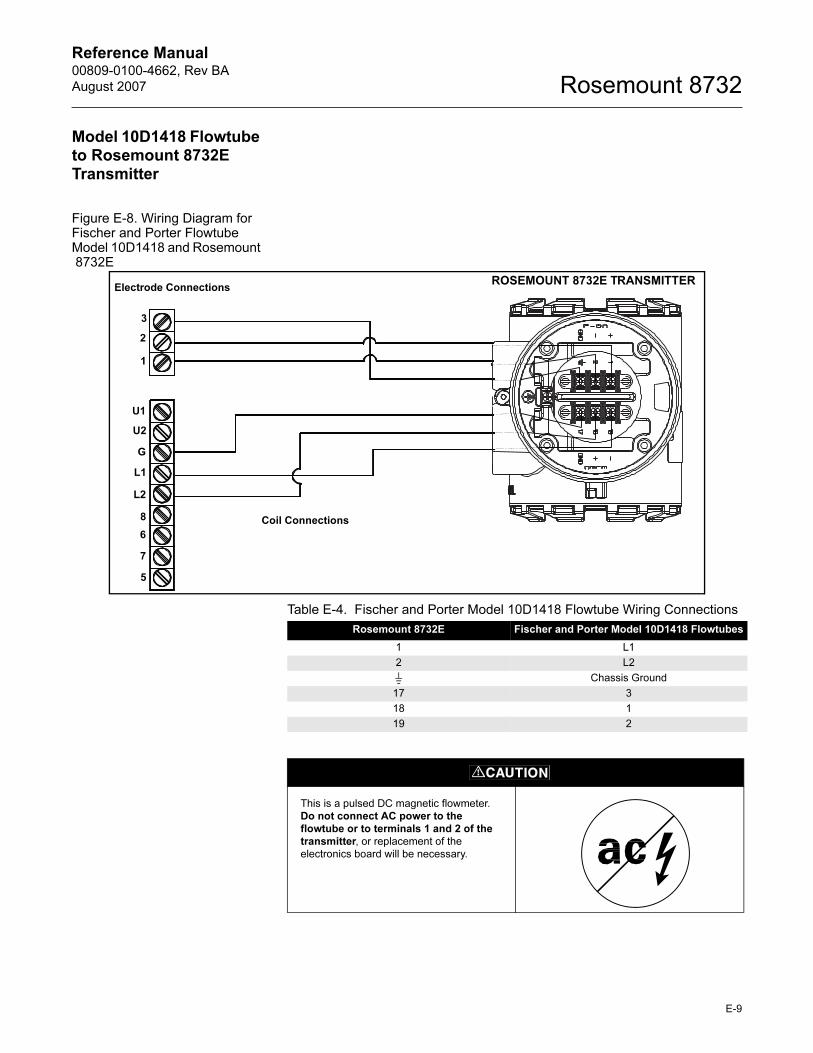
Reference Manual 00809-0100-4662, Rev BA
August 2007 Rosemount 8732
Model 10D1418 Flowtube to Rosemount 8732E Transmitter
Figure E-8. Wiring Diagram for Fischer and Porter Flowtube Model 10D1418 and Rosemount 8732E
ROSEMOUNT 8732E TRANSMITTERElectrode Connections
U1
U2
G
8
6
7
L1
L2
5
3
2
1
Coil Connections
Table E-4. Fischer and Porter Model 10D1418 Flowtube Wiring Connections
Rosemount 8732E Fischer and Porter Model 10D1418 Flowtubes
1 L1
2 L2
Chassis Ground
17 3
18 1
19 2
This is a pulsed DC magnetic flowmeter.
Do not connect AC power to the flowtube or to terminals 1 and 2 of the transmitter, or replacement of the
electronics board will be necessary.
E-9
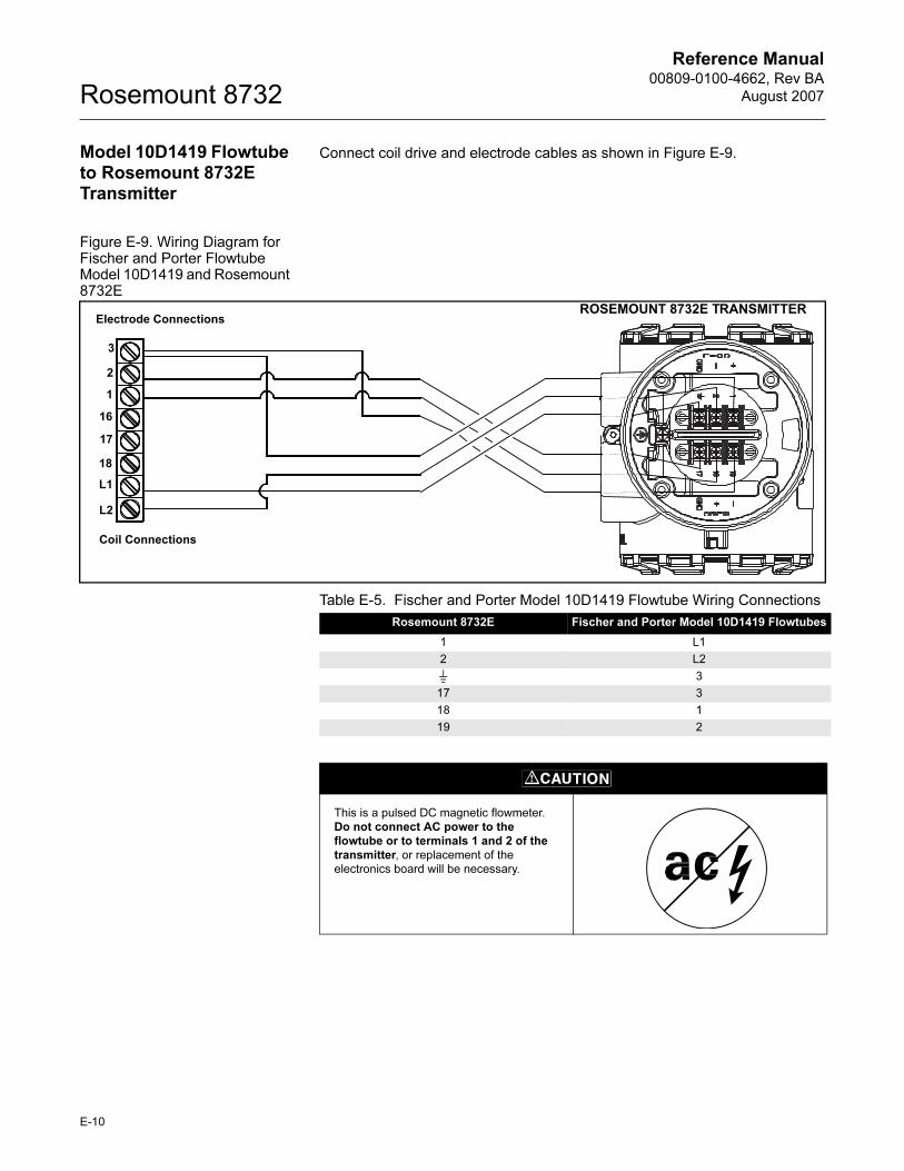
Reference Manual00809-0100-4662, Rev BA
August 2007Rosemount 8732
Model 10D1419 Flowtube to Rosemount 8732E Transmitter
Connect coil drive and electrode cables as shown in Figure E-9.
Figure E-9. Wiring Diagram for Fischer and Porter Flowtube Model 10D1419 and Rosemount 8732E
ROSEMOUNT 8732E TRANSMITTER
3
2
1
18
L1
L2
16
17
Electrode Connections
Coil Connections
Table E-5. Fischer and Porter Model 10D1419 Flowtube Wiring Connections
Rosemount 8732E Fischer and Porter Model 10D1419 Flowtubes
1 L1
2 L2
3
17 3
18 1
19 2
This is a pulsed DC magnetic flowmeter.
Do not connect AC power to the flowtube or to terminals 1 and 2 of the transmitter, or replacement of the
electronics board will be necessary.
E-10

Reference Manual 00809-0100-4662, Rev BA
August 2007 Rosemount 8732
Model 10D1430 Flowtube (Remote) to Rosemount 8732E Transmitter
Connect coil drive and electrode cables as shown in Figure E-10.
Figure E-10. Wiring Diagram for Fischer and Porter Flowtube Model 10D1430 (Remote) and Rosemount 8732E
ROSEMOUNT 8732E TRANSMITTER
1
2
3
G
L1
8
Coil Connections
Electrode Connections
Table E-6. Fischer and Porter Model 10D1430 (Remote) Flowtube Wiring Connections
Rosemount 8732E
Fischer and Porter Model 10D1430 (Remote)
Flowtubes
1 L1
2 8
G
17 3
18 1
19 2
This is a pulsed DC magnetic flowmeter.
Do not connect AC power to the flowtube or to terminals 1 and 2 of the transmitter, or replacement of the
electronics board will be necessary.
E-11
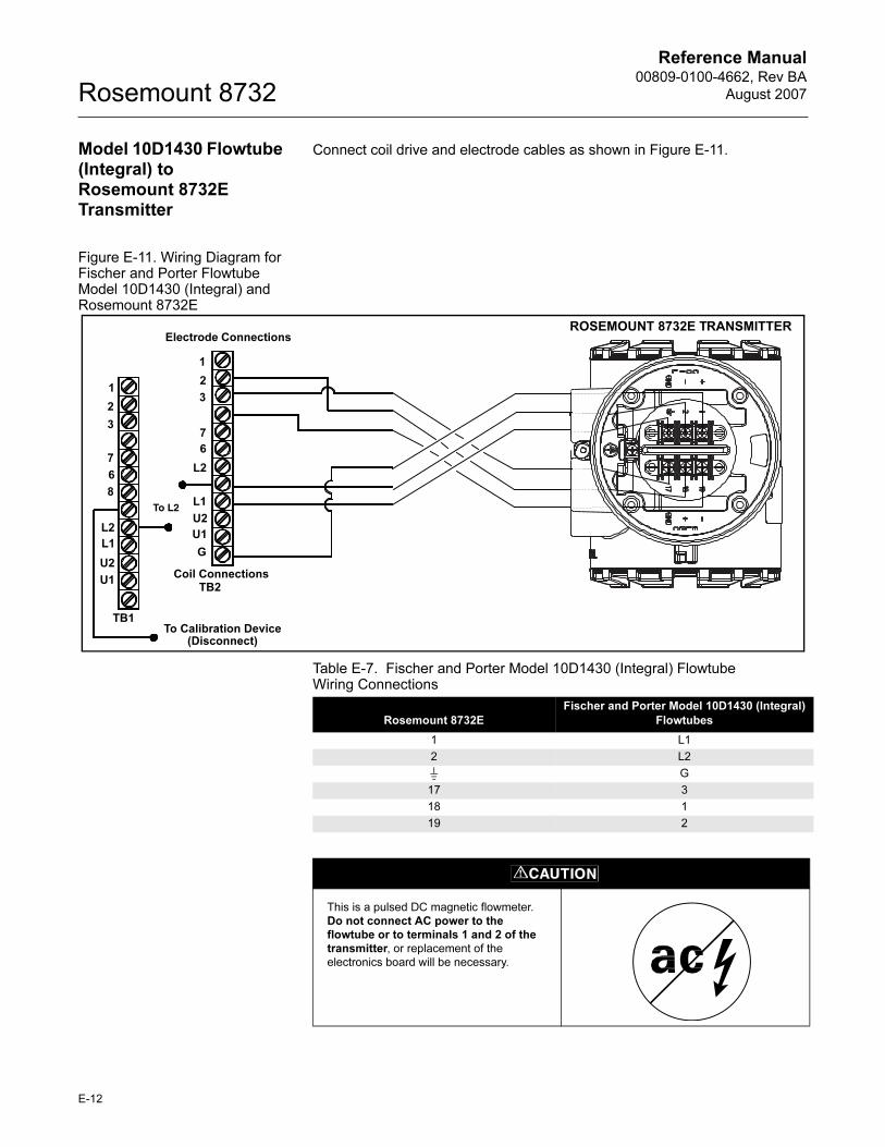
Reference Manual00809-0100-4662, Rev BA
August 2007Rosemount 8732
Model 10D1430 Flowtube (Integral) to Rosemount 8732E Transmitter
Connect coil drive and electrode cables as shown in Figure E-11.
Figure E-11. Wiring Diagram for Fischer and Porter Flowtube Model 10D1430 (Integral) and Rosemount 8732E
Electrode ConnectionsROSEMOUNT 8732E TRANSMITTER
To L2
1
2
3
7
6
8
L2
L1
U2
U1
1
2
3
7
6
L2
L1
U2
U1
G
TB1
TB2Coil Connections
To Calibration Device(Disconnect)
Table E-7. Fischer and Porter Model 10D1430 (Integral) Flowtube Wiring Connections
Rosemount 8732E
Fischer and Porter Model 10D1430 (Integral)
Flowtubes
1 L1
2 L2
G
17 3
18 1
19 2
This is a pulsed DC magnetic flowmeter.
Do not connect AC power to the flowtube or to terminals 1 and 2 of the transmitter, or replacement of the
electronics board will be necessary.
E-12
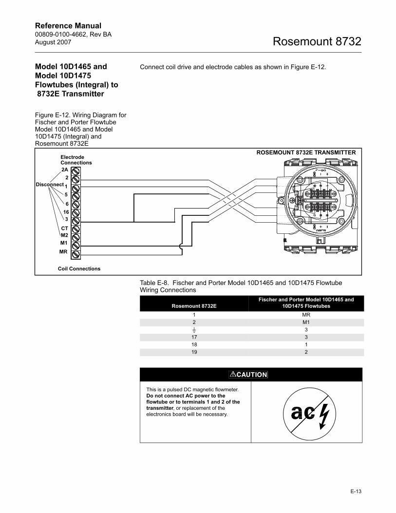
Reference Manual 00809-0100-4662, Rev BA
August 2007 Rosemount 8732
Model 10D1465 and Model 10D1475 Flowtubes (Integral) to 8732E Transmitter
Connect coil drive and electrode cables as shown in Figure E-12.
Figure E-12. Wiring Diagram for Fischer and Porter Flowtube Model 10D1465 and Model 10D1475 (Integral) and Rosemount 8732E
2A
2
1
5
6
16
3
CT
M2
M1
MR
Electrode Connections
Coil Connections
ROSEMOUNT 8732E TRANSMITTER
Disconnect
Table E-8. Fischer and Porter Model 10D1465 and 10D1475 Flowtube Wiring Connections
Rosemount 8732E
Fischer and Porter Model 10D1465 and
10D1475 Flowtubes
1 MR
2 M1
3
17 3
18 1
19 2
This is a pulsed DC magnetic flowmeter.
Do not connect AC power to the flowtube or to terminals 1 and 2 of the transmitter, or replacement of the
electronics board will be necessary.
E-13
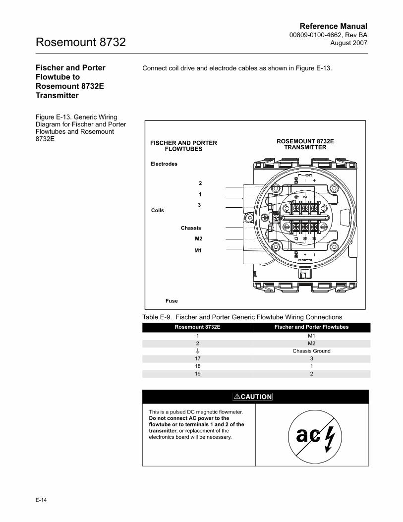
Reference Manual00809-0100-4662, Rev BA
August 2007Rosemount 8732
Fischer and Porter Flowtube to Rosemount 8732E Transmitter
Connect coil drive and electrode cables as shown in Figure E-13.
Figure E-13. Generic Wiring Diagram for Fischer and Porter Flowtubes and Rosemount 8732E
Table E-9. Fischer and Porter Generic Flowtube Wiring Connections
Rosemount 8732E Fischer and Porter Flowtubes
1 M1
2 M2
Chassis Ground
17 3
18 1
19 2
Electrodes
2
Coils
Chassis
ROSEMOUNT 8732E TRANSMITTER
FISCHER AND PORTER FLOWTUBES
Fuse
1
3
M2
M1
This is a pulsed DC magnetic flowmeter.
Do not connect AC power to the flowtube or to terminals 1 and 2 of the transmitter, or replacement of the
electronics board will be necessary.
E-14
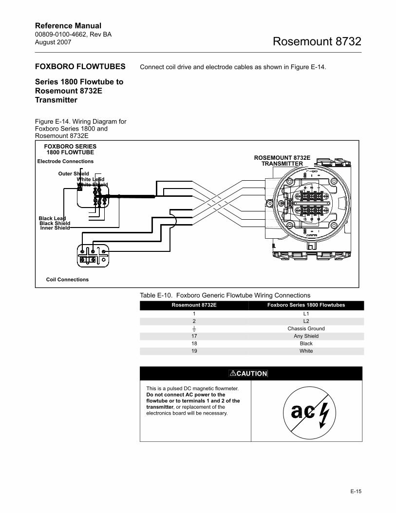
Reference Manual 00809-0100-4662, Rev BA
August 2007 Rosemount 8732
FOXBORO FLOWTUBES Connect coil drive and electrode cables as shown in Figure E-14.
Series 1800 Flowtube to Rosemount 8732E Transmitter
Figure E-14. Wiring Diagram for Foxboro Series 1800 and Rosemount 8732E
ROSEMOUNT 8732E TRANSMITTER
Coil Connections
Electrode Connections
FOXBORO SERIES 1800 FLOWTUBE
Outer ShieldWhite LeadWhite Shield
Black LeadBlack ShieldInner Shield
Table E-10. Foxboro Generic Flowtube Wiring Connections
Rosemount 8732E Foxboro Series 1800 Flowtubes
1 L1
2 L2
Chassis Ground
17 Any Shield
18 Black
19 White
This is a pulsed DC magnetic flowmeter.
Do not connect AC power to the flowtube or to terminals 1 and 2 of the transmitter, or replacement of the
electronics board will be necessary.
E-15
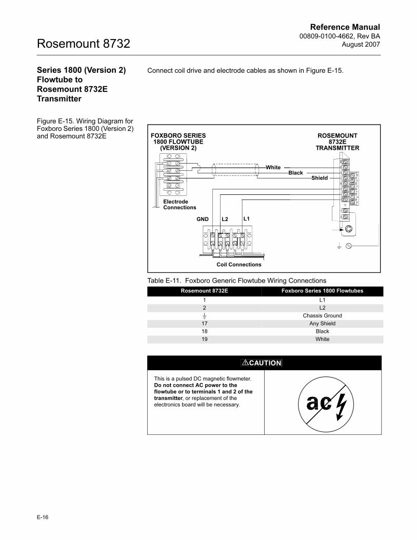
Reference Manual00809-0100-4662, Rev BA
August 2007Rosemount 8732
Series 1800 (Version 2) Flowtube to Rosemount 8732E Transmitter
Connect coil drive and electrode cables as shown in Figure E-15.
Figure E-15. Wiring Diagram for Foxboro Series 1800 (Version 2) and Rosemount 8732E
Table E-11. Foxboro Generic Flowtube Wiring Connections
Rosemount 8732E Foxboro Series 1800 Flowtubes
1 L1
2 L2
Chassis Ground
17 Any Shield
18 Black
19 White
FOXBORO SERIES 1800 FLOWTUBE
(VERSION 2)
ROSEMOUNT 8732E
TRANSMITTER
Coil Connections
Electrode Connections
GND L2 L1
WhiteBlack
Shield
This is a pulsed DC magnetic flowmeter.
Do not connect AC power to the flowtube or to terminals 1 and 2 of the transmitter, or replacement of the
electronics board will be necessary.
E-16
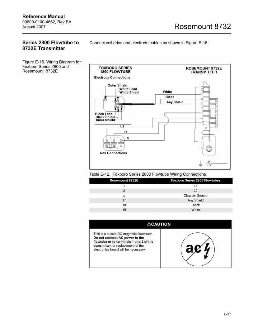
Reference Manual 00809-0100-4662, Rev BA
August 2007 Rosemount 8732
Series 2800 Flowtube to 8732E Transmitter
Connect coil drive and electrode cables as shown in Figure E-16.
Figure E-16. Wiring Diagram for Foxboro Series 2800 and Rosemount 8732E
Table E-12. Foxboro Series 2800 Flowtube Wiring Connections
Rosemount 8732E Foxboro Series 2800 Flowtubes
1 L1
2 L2
Chassis Ground
17 Any Shield
18 Black
19 White
ROSEMOUNT 8732E TRANSMITTER
Coil Connections
Electrode Connections
FOXBORO SERIES 1800 FLOWTUBE
Outer ShieldWhite LeadWhite Shield
Black LeadBlack ShieldInner Shield
White
Black
Any Shield
L2
L1
G
This is a pulsed DC magnetic flowmeter.
Do not connect AC power to the flowtube or to terminals 1 and 2 of the transmitter, or replacement of the
electronics board will be necessary.
E-17
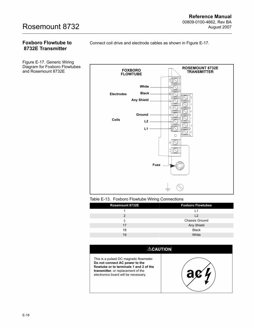
Reference Manual00809-0100-4662, Rev BA
August 2007Rosemount 8732
Foxboro Flowtube to 8732E Transmitter
Connect coil drive and electrode cables as shown in Figure E-17.
Figure E-17. Generic Wiring Diagram for Foxboro Flowtubes and Rosemount 8732E
Table E-13. Foxboro Flowtube Wiring Connections
Rosemount 8732E Foxboro Flowtubes
1 L1
2 L2
Chassis Ground
17 Any Shield
18 Black
19 White
Electrodes
Coils
Ground
ROSEMOUNT 8732E TRANSMITTERFOXBORO
FLOWTUBE
L2
L1
White
Black
Any Shield
Fuse
This is a pulsed DC magnetic flowmeter.
Do not connect AC power to the flowtube or to terminals 1 and 2 of the transmitter, or replacement of the
electronics board will be necessary.
E-18
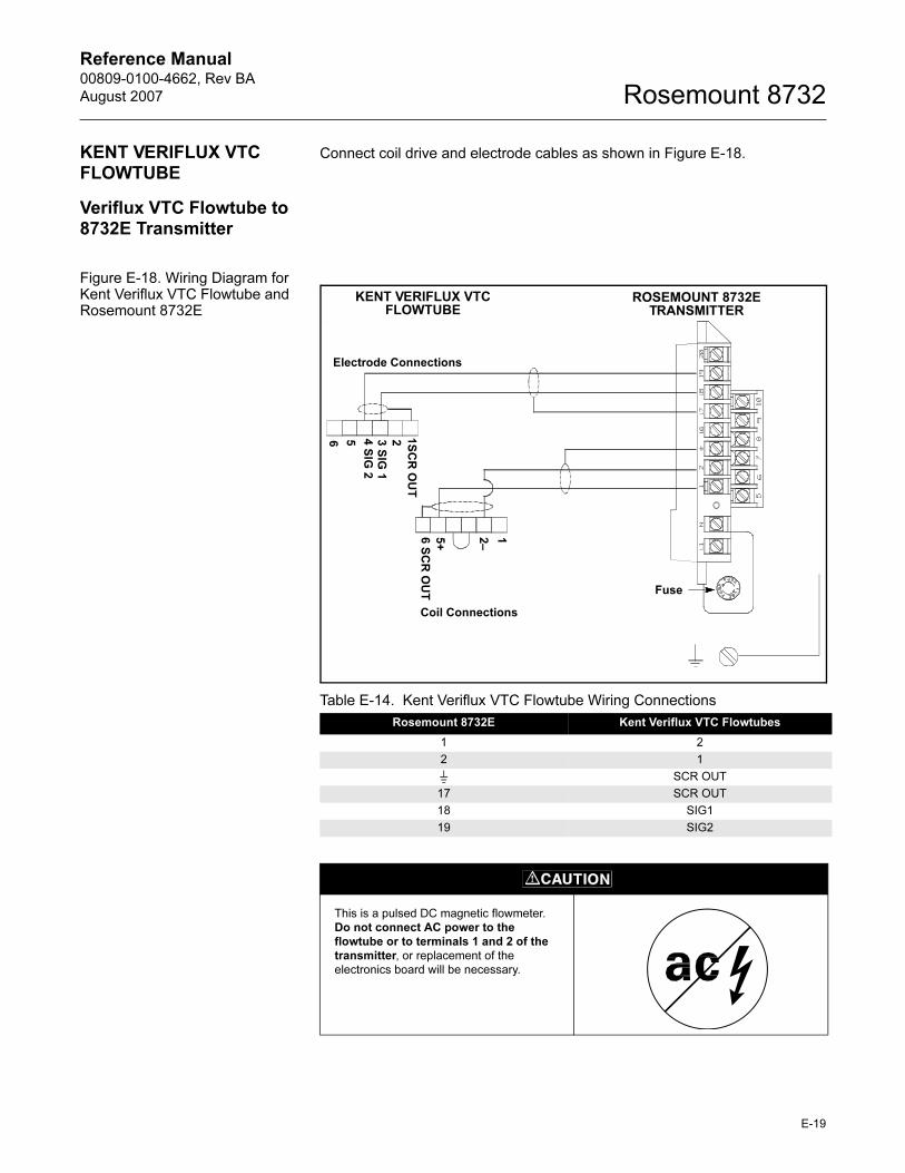
Reference Manual 00809-0100-4662, Rev BA
August 2007 Rosemount 8732
KENT VERIFLUX VTC FLOWTUBE
Connect coil drive and electrode cables as shown in Figure E-18.
Veriflux VTC Flowtube to 8732E Transmitter
Figure E-18. Wiring Diagram for Kent Veriflux VTC Flowtube and Rosemount 8732E
Table E-14. Kent Veriflux VTC Flowtube Wiring Connections
Rosemount 8732E Kent Veriflux VTC Flowtubes
1 2
2 1
SCR OUT
17 SCR OUT
18 SIG1
19 SIG2
Electrode Connections
Coil Connections
ROSEMOUNT 8732E TRANSMITTER
KENT VERIFLUX VTC FLOWTUBE
1S
CR
OU
T
23 S
IG 1
4 S
IG 2
56
12–
5+
6 S
CR
OU
T Fuse
This is a pulsed DC magnetic flowmeter.
Do not connect AC power to the flowtube or to terminals 1 and 2 of the transmitter, or replacement of the
electronics board will be necessary.
E-19
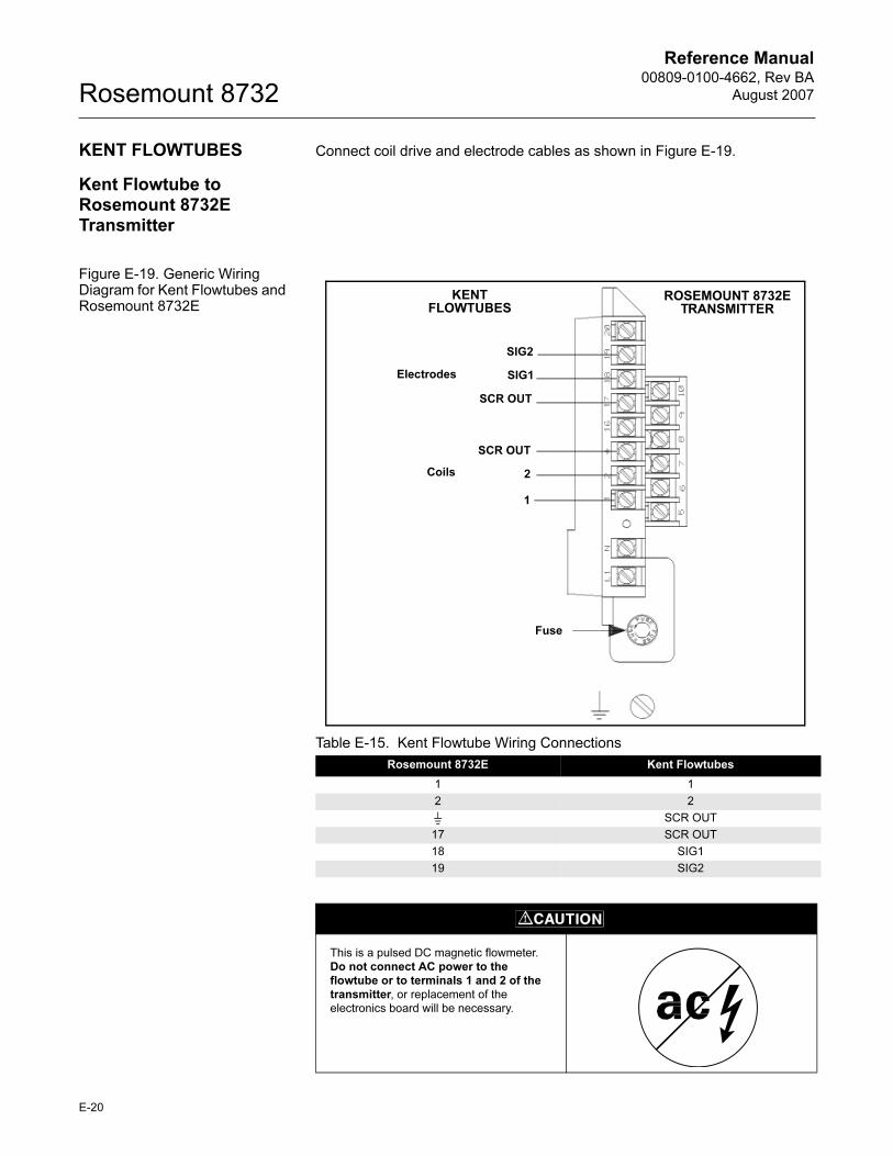
Reference Manual00809-0100-4662, Rev BA
August 2007Rosemount 8732
KENT FLOWTUBES Connect coil drive and electrode cables as shown in Figure E-19.
Kent Flowtube to Rosemount 8732E Transmitter
Figure E-19. Generic Wiring Diagram for Kent Flowtubes and Rosemount 8732E
Table E-15. Kent Flowtube Wiring Connections
Rosemount 8732E Kent Flowtubes
1 1
2 2
SCR OUT
17 SCR OUT
18 SIG1
19 SIG2
Coils
Electrodes
SCR OUT
ROSEMOUNT 8732E TRANSMITTER
KENT FLOWTUBES
2
1
SIG2
SIG1
SCR OUT
Fuse
This is a pulsed DC magnetic flowmeter.
Do not connect AC power to the flowtube or to terminals 1 and 2 of the transmitter, or replacement of the
electronics board will be necessary.
E-20
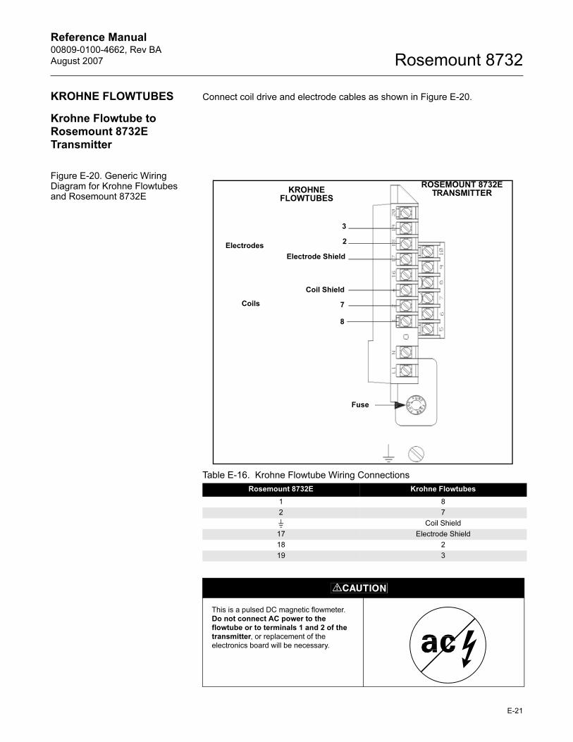
Reference Manual 00809-0100-4662, Rev BA
August 2007 Rosemount 8732
KROHNE FLOWTUBES Connect coil drive and electrode cables as shown in Figure E-20.
Krohne Flowtube to Rosemount 8732E Transmitter
Figure E-20. Generic Wiring Diagram for Krohne Flowtubes and Rosemount 8732E
Table E-16. Krohne Flowtube Wiring Connections
Rosemount 8732E Krohne Flowtubes
1 8
2 7
Coil Shield
17 Electrode Shield
18 2
19 3
Electrodes
Coils
Coil Shield
ROSEMOUNT 8732E TRANSMITTERKROHNE
FLOWTUBES
7
8
3
2
Electrode Shield
Fuse
This is a pulsed DC magnetic flowmeter.
Do not connect AC power to the flowtube or to terminals 1 and 2 of the transmitter, or replacement of the
electronics board will be necessary.
E-21
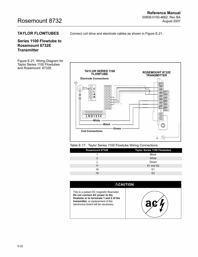
Reference Manual00809-0100-4662, Rev BA
August 2007Rosemount 8732
TAYLOR FLOWTUBES Connect coil drive and electrode cables as shown in Figure E-21.
Series 1100 Flowtube to Rosemount 8732E Transmitter
Figure E-21. Wiring Diagram for Taylor Series 1100 Flowtubes and Rosemount 8732E
Table E-17. Taylor Series 1100 Flowtube Wiring Connections
Rosemount 8732E Taylor Series 1100 Flowtubes
1 Black
2 White
Green
17 S1 and S2
18 E1
19 E2
ROSEMOUNT 8732E TRANSMITTER
Electrode Connections
Coil Connections
TAYLOR SERIES 1100 FLOWTUBE
CLAR
White
Black
Green
L N G 1 2 3 4
This is a pulsed DC magnetic flowmeter.
Do not connect AC power to the flowtube or to terminals 1 and 2 of the transmitter, or replacement of the
electronics board will be necessary.
E-22
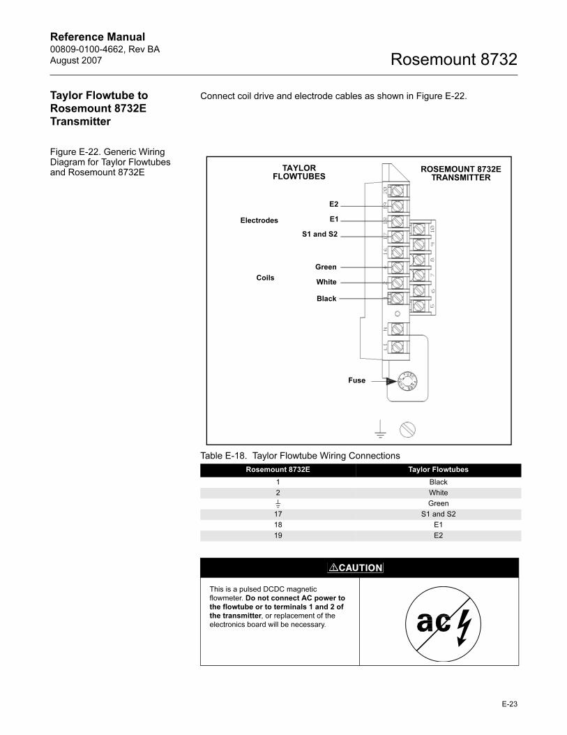
Reference Manual 00809-0100-4662, Rev BA
August 2007 Rosemount 8732
Taylor Flowtube to Rosemount 8732E Transmitter
Connect coil drive and electrode cables as shown in Figure E-22.
Figure E-22. Generic Wiring Diagram for Taylor Flowtubes and Rosemount 8732E
Table E-18. Taylor Flowtube Wiring Connections
Rosemount 8732E Taylor Flowtubes
1 Black
2 White
Green
17 S1 and S2
18 E1
19 E2
Electrodes
Coils
Green
ROSEMOUNT 8732E TRANSMITTER
TAYLOR FLOWTUBES
White
Black
E2
E1
S1 and S2
Fuse
This is a pulsed DCDC magnetic
flowmeter. Do not connect AC power to the flowtube or to terminals 1 and 2 of the transmitter, or replacement of the
electronics board will be necessary.
E-23
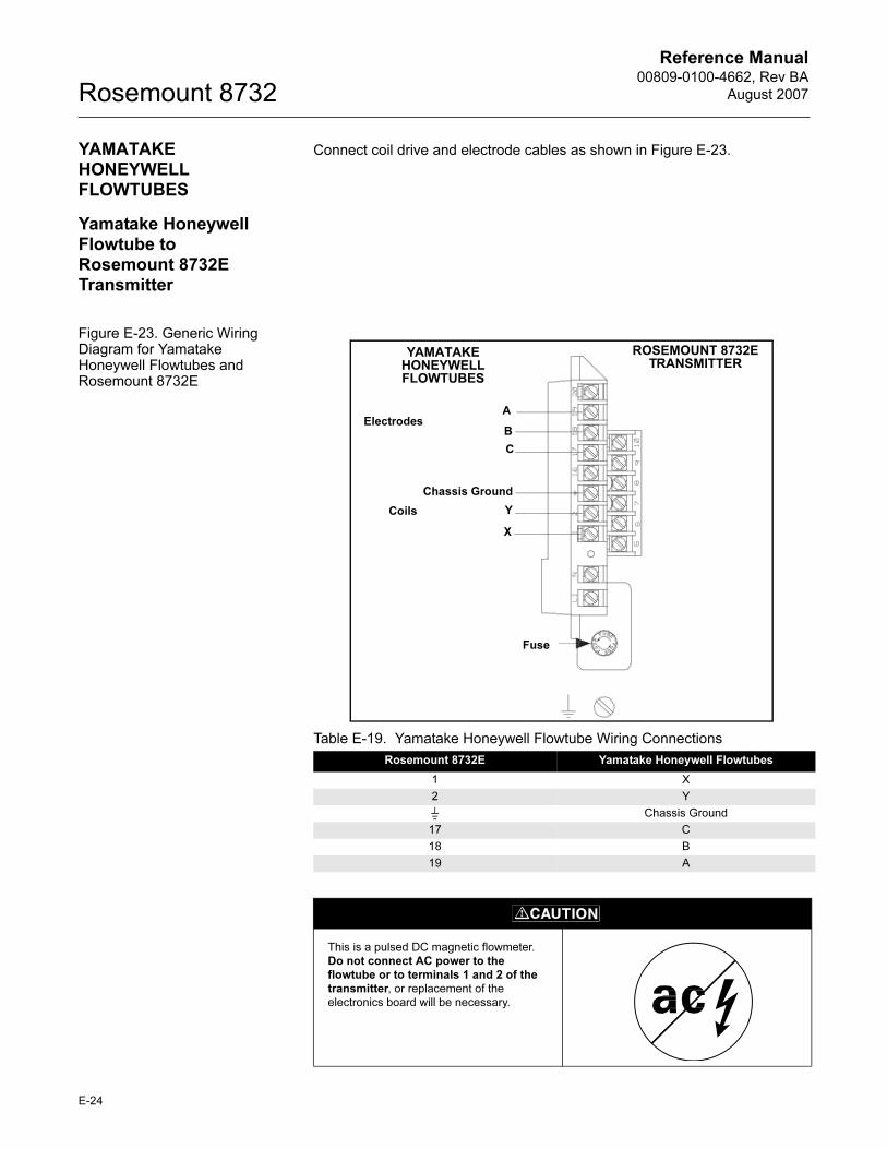
Reference Manual00809-0100-4662, Rev BA
August 2007Rosemount 8732
YAMATAKE HONEYWELL FLOWTUBES
Connect coil drive and electrode cables as shown in Figure E-23.
Yamatake Honeywell Flowtube to Rosemount 8732E Transmitter
Figure E-23. Generic Wiring Diagram for Yamatake Honeywell Flowtubes and Rosemount 8732E
Table E-19. Yamatake Honeywell Flowtube Wiring Connections
Rosemount 8732E Yamatake Honeywell Flowtubes
1 X
2 Y
Chassis Ground
17 C
18 B
19 A
Electrodes
Coils
Chassis Ground
ROSEMOUNT 8732E TRANSMITTER
YAMATAKE HONEYWELL FLOWTUBES
Y
X
A
B
C
Fuse
This is a pulsed DC magnetic flowmeter.
Do not connect AC power to the flowtube or to terminals 1 and 2 of the transmitter, or replacement of the
electronics board will be necessary.
E-24
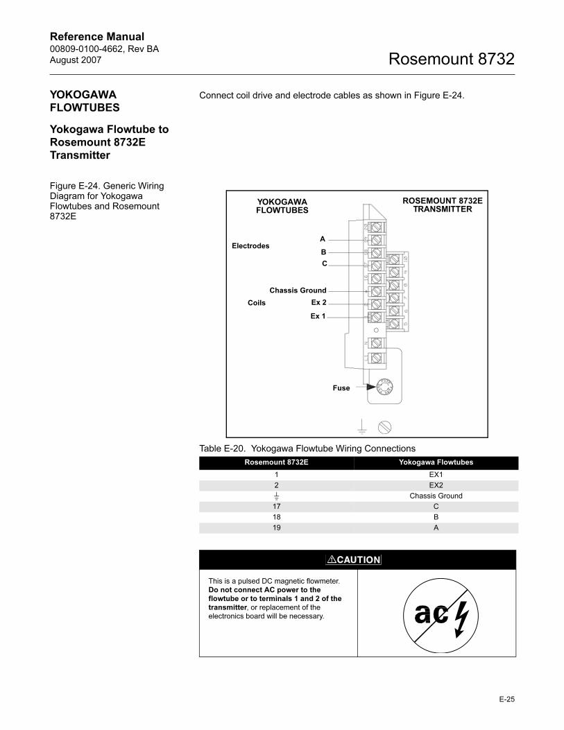
Reference Manual 00809-0100-4662, Rev BA
August 2007 Rosemount 8732
YOKOGAWA FLOWTUBES
Connect coil drive and electrode cables as shown in Figure E-24.
Yokogawa Flowtube to Rosemount 8732E Transmitter
Figure E-24. Generic Wiring Diagram for Yokogawa Flowtubes and Rosemount 8732E
Table E-20. Yokogawa Flowtube Wiring Connections
Rosemount 8732E Yokogawa Flowtubes
1 EX1
2 EX2
Chassis Ground
17 C
18 B
19 A
Electrodes
Coils
Chassis Ground
ROSEMOUNT 8732E TRANSMITTER
YOKOGAWA FLOWTUBES
Ex 2
Ex 1
A
B
C
Fuse
This is a pulsed DC magnetic flowmeter.
Do not connect AC power to the flowtube or to terminals 1 and 2 of the transmitter, or replacement of the
electronics board will be necessary.
E-25
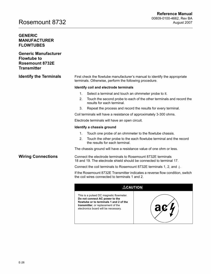
Reference Manual00809-0100-4662, Rev BA
August 2007Rosemount 8732
GENERIC MANUFACTURER FLOWTUBES
Generic Manufacturer Flowtube to Rosemount 8732E Transmitter
Identify the Terminals First check the flowtube manufacturer’s manual to identify the appropriate terminals. Otherwise, perform the following procedure.
Identify coil and electrode terminals
1. Select a terminal and touch an ohmmeter probe to it.
2. Touch the second probe to each of the other terminals and record the results for each terminal.
3. Repeat the process and record the results for every terminal.
Coil terminals will have a resistance of approximately 3-300 ohms.
Electrode terminals will have an open circuit.
Identify a chassis ground
1. Touch one probe of an ohmmeter to the flowtube chassis.
2. Touch the other probe to the each flowtube terminal and the record the results for each terminal.
The chassis ground will have a resistance value of one ohm or less.
Wiring Connections Connect the electrode terminals to Rosemount 8732E terminals 18 and 19. The electrode shield should be connected to terminal 17.
Connect the coil terminals to Rosemount 8732E terminals 1, 2, and .
If the Rosemount 8732E Transmitter indicates a reverse flow condition, switch the coil wires connected to terminals 1 and 2.
This is a pulsed DC magnetic flowmeter.
Do not connect AC power to the flowtube or to terminals 1 and 2 of the transmitter, or replacement of the
electronics board will be necessary.
E-26
Reference Manual 00809-0100-4662, Rev BA
August 2007 Rosemount 8732
Appendix F HART Field Communicator Operation
HandHeld Communicator . . . . . . . . . . . . . . . . . . . . . . . . . . page F-1
Connections and Hardware . . . . . . . . . . . . . . . . . . . . . . . . page F-7
Basic Features . . . . . . . . . . . . . . . . . . . . . . . . . . . . . . . . . . page F-8
Menus and Functions . . . . . . . . . . . . . . . . . . . . . . . . . . . . . page F-10
HANDHELD COMMUNICATOR
NOTEPlease refer to the Handheld Communicator manual for detailed instructions on the use, features, and full capabilities of the Handheld Communicator.
Explosions can result in death or serious injury.
Do not make connections to the serial port or NiCad recharger jack in an
explosive atmosphere.
Before connecting the Handheld Communicator in an explosive atmosphere, make sure the
instruments in the loop are installed in accordance with intrinsically safe or nonincendive
field wiring practices.
www.rosemount.com
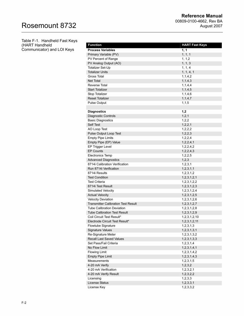
Reference Manual00809-0100-4662, Rev BA
August 2007Rosemount 8732
Table F-1. Handheld Fast Keys (HART Handheld Communicator) and LOI Keys
Function HART Fast Keys
Process Variables 1, 1
Primary Variable (PV) 1, 1, 1
PV Percent of Range 1, 1,2
PV Analog Output (AO) 1, 1, 3
Totalizer Set-Up 1, 1, 4
Totalizer Units 1, 1, 4, 1
Gross Total 1,1,4,2
Net Total 1,1,4,3
Reverse Total 1,1,4,4
Start Totalizer 1,1,4,5
Stop Totalizer 1,1,4,6
Reset Totalizer 1,1,4,7
Pulse Output 1,1,5
Diagnostics 1,2
Diagnostic Controls 1,2,1
Basic Diagnostics 1,2,2
Self Test 1,2,2,1
AO Loop Test 1,2,2,2
Pulse Output Loop Test 1,2,2,3
Empty Pipe Limits 1,2,2,4
Empty Pipe (EP) Value 1,2,2,4,1
EP Trigger Level 1,2,2,4,2
EP Counts 1,2,2,4,3
Electronics Temp 1,2,2,5
Advanced Diagnostics 1,2,3
8714i Calibration Verification 1,2,3,1
Run 8714i Verification 1,2,3,1,1
8714i Results 1,2,3,1,2
Test Condition 1,2,3,1,2,1
Test Criteria 1,2,3,1,2,2
8714i Test Result 1,2,3,1,2,3
Simulated Velocity 1,2,3,1,2,4
Actual Velocity 1,2,3,1,2,5
Velocity Deviation 1,2,3,1,2,6
Transmitter Calibration Test Result 1,2,3,1,2,7
Tube Calibration Deviation 1,2,3,1,2,8
Tube Calibration Test Result 1,2,3,1,2,9
Coil Circuit Test Result* 1,2,3,1,2,10
Electrode Circuit Test Result* 1,2,3,1,2,11
Flowtube Signature 1,2,3,1,3
Signature Values 1,2,3,1,3,1
Re-Signature Meter 1,2,3,1,3,2
Recall Last Saved Values 1,2,3,1,3,3
Set Pass/Fail Criteria 1,2,3,1,4
No Flow Limit 1,2,3,1,4,1
Flowing Limit 1,2,3,1,4,2
Empty Pipe Limit 1,2,3,1,4,3
Measurements 1,2,3,1,5
4-20 mA Verify 1,2,3,2
4-20 mA Verification 1,2,3,2,1
4-20 mA Verify Result 1,2,3,2,2
Licensing 1,2,3,3
License Status 1,2,3,3,1
License Key 1,2,3,3,2
F-2
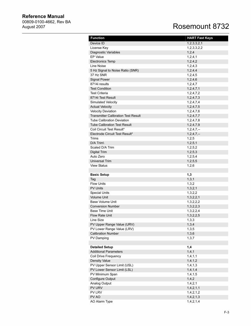
Reference Manual 00809-0100-4662, Rev BA
August 2007 Rosemount 8732
Device ID 1,2,3,3,2,1
License Key 1,2,3,3,2,2
Diagnostic Variables 1,2,4
EP Value 1,2,4,1
Electronics Temp 1,2,4,2
Line Noise 1,2,4,3
5 Hz Signal to Noise Ratio (SNR) 1,2,4,4
37 Hz SNR 1,2,4,5
Signal Power 1,2,4,6
8714i results 1,2,4,7
Test Condition 1,2,4,7,1
Test Criteria 1,2,4,7,2
8714i Test Result 1,2,4,7,3
Simulated Velocity 1,2,4,7,4
Actual Velocity 1,2,4,7,5
Velocity Deviation 1,2,4,7,6
Transmitter Calibration Test Result 1,2,4,7,7
Tube Calibration Deviation 1,2,4,7,8
Tube Calibration Test Result 1,2,4,7,9
Coil Circuit Test Result* 1,2,4,7,--
Electrode Circuit Test Result* 1,2,4,7,--
Trims 1,2,5
D/A Trim\ 1,2,5,1
Scaled D/A Trim 1,2,5,2
Digital Trim 1,2,5,3
Auto Zero 1,2,5,4
Universal Trim 1,2,5,5
View Status 1,2,6
Basic Setup 1,3
Tag 1,3,1
Flow Units 1,3,2
PV Units 1,3,2,1
Special Units 1,3,2,2
Volume Unit 1,3,2,2,1
Base Volume Unit 1,3,2,2,2
Conversion Number 1,3,2,2,3
Base Time Unit 1,3,2,2,4
Flow Rate Unit 1,3,2,2,5
Line Size 1,3,3
PV Upper Range Value (URV) 1,3,4
PV Lower Range Value (LRV) 1,3,5
Calibration Number 1,3,6
PV Damping 1,3,7
Detailed Setup 1,4
Additional Parameters 1,4,1
Coil Drive Frequency 1,4,1,1
Density Value 1,4,1,2
PV Upper Sensor Limit (USL) 1,4,1,3
PV Lower Sensor Limit (LSL) 1,4,1,4
PV Minimum Span 1,4,1,5
Configure Output 1,4,2
Analog Output 1,4,2,1
PV URV 1,4,2,1,1
PV LRV 1,4,2,1,2
PV AO 1,4,2,1,3
AO Alarm Type 1,4,2,1,4
Function HART Fast Keys
F-3
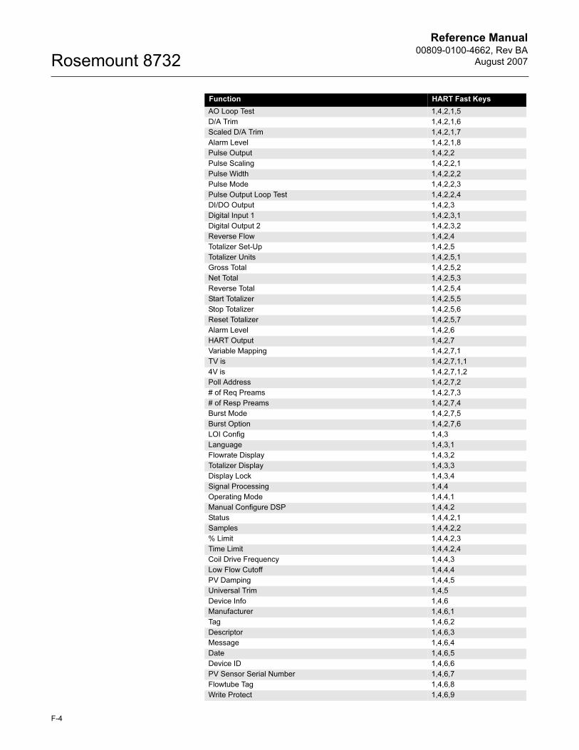
Reference Manual00809-0100-4662, Rev BA
August 2007Rosemount 8732
AO Loop Test 1,4,2,1,5
D/A Trim 1,4,2,1,6
Scaled D/A Trim 1,4,2,1,7
Alarm Level 1,4,2,1,8
Pulse Output 1,4,2,2
Pulse Scaling 1,4,2,2,1
Pulse Width 1,4,2,2,2
Pulse Mode 1,4,2,2,3
Pulse Output Loop Test 1,4,2,2,4
DI/DO Output 1,4,2,3
Digital Input 1 1,4,2,3,1
Digital Output 2 1,4,2,3,2
Reverse Flow 1,4,2,4
Totalizer Set-Up 1,4,2,5
Totalizer Units 1,4,2,5,1
Gross Total 1,4,2,5,2
Net Total 1,4,2,5,3
Reverse Total 1,4,2,5,4
Start Totalizer 1,4,2,5,5
Stop Totalizer 1,4,2,5,6
Reset Totalizer 1,4,2,5,7
Alarm Level 1,4,2,6
HART Output 1,4,2,7
Variable Mapping 1,4,2,7,1
TV is 1,4,2,7,1,1
4V is 1,4,2,7,1,2
Poll Address 1,4,2,7,2
# of Req Preams 1,4,2,7,3
# of Resp Preams 1,4,2,7,4
Burst Mode 1,4,2,7,5
Burst Option 1,4,2,7,6
LOI Config 1,4,3
Language 1,4,3,1
Flowrate Display 1,4,3,2
Totalizer Display 1,4,3,3
Display Lock 1,4,3,4
Signal Processing 1,4,4
Operating Mode 1,4,4,1
Manual Configure DSP 1,4,4,2
Status 1,4,4,2,1
Samples 1,4,4,2,2
% Limit 1,4,4,2,3
Time Limit 1,4,4,2,4
Coil Drive Frequency 1,4,4,3
Low Flow Cutoff 1,4,4,4
PV Damping 1,4,4,5
Universal Trim 1,4,5
Device Info 1,4,6
Manufacturer 1,4,6,1
Tag 1,4,6,2
Descriptor 1,4,6,3
Message 1,4,6,4
Date 1,4,6,5
Device ID 1,4,6,6
PV Sensor Serial Number 1,4,6,7
Flowtube Tag 1,4,6,8
Write Protect 1,4,6,9
Function HART Fast Keys
F-4
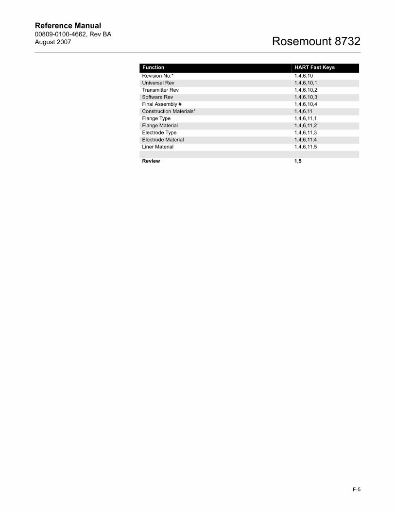
Reference Manual 00809-0100-4662, Rev BA
August 2007 Rosemount 8732
Revision No.* 1,4,6,10
Universal Rev 1,4,6,10,1
Transmitter Rev 1,4,6,10,2
Software Rev 1,4,6,10,3
Final Assembly # 1,4,6,10,4
Construction Materials* 1,4,6,11
Flange Type 1,4,6,11,1
Flange Material 1,4,6,11,2
Electrode Type 1,4,6,11,3
Electrode Material 1,4,6,11,4
Liner Material 1,4,6,11,5
Review 1,5
Function HART Fast Keys
F-5
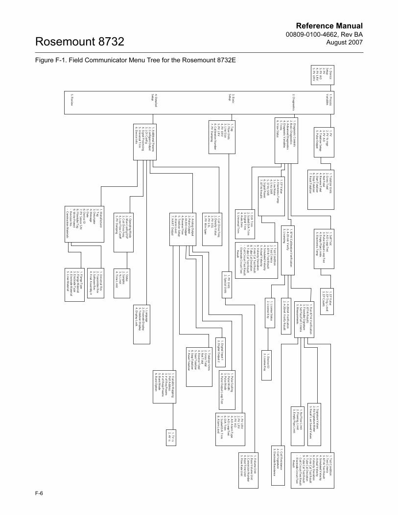
Reference Manual00809-0100-4662, Rev BA
August 2007Rosemount 8732
F-6
Figure F-1. Field Communicator Menu Tree for the Rosemount 8732E1. D
evice Setup2. PV
3. PV
AO
4. PV
LR
V
5. PV U
RV
1. PV
2. PV %
rnge 3. PV
AO
4. T
otalizer Setup 5. Pulse O
utput
1. Totalizer U
nits 2. G
ross Total
3. Net T
otal 4. R
everse Total
5. Start Totalizer
6. Stop Totalizer
7. Reset T
otalizer
1. Diagnostic C
ontrols 2. B
asic Diagnostics
3. Advanced D
iagnostics 4. D
iagnostic Variables
5. Trim
s 6. V
iew Status
1. Process V
ariables
2. Diagnostics
3. Basic
Setup
4. Detailed
Setup
5. Review
1. Self Test
2. AO
Loop T
est 3. Pulse O
utput Loop T
est 4. E
mpty Pipe L
imits
5. Electronics T
emp
1. EP V
alue 2. E
lectronics Tem
p 3. L
ine Noise
4. 5 Hz SN
R
5. 37 Hz SN
R
6. Signal Power
7. 8714i Results
1. PV U
nits 2. Special U
nits
1. Volum
e Unit
2. Base V
olume U
nit 3. C
onversion Num
ber 4. B
ase Tim
e Unit
5. Flow R
ate Unit
1. Analog O
utput 2. Pulse O
utput 3. D
I/DO
Output
4. Reverse Flow
5. T
otalizer Setup 6. A
larm L
evel 7. H
AR
T O
utput
1. PV U
RV
2. PV
LR
V
3. PV A
O
4. AO
Alarm
Type
5. AO
Loop T
est 6. D
/A T
rim
7. Scaled D/A
Trim
8. A
larm L
evel
1. Pulse Scaling 2. Pulse W
idth 3. Pulse M
ode 4. Pulse O
utput Loop T
est
1. Totalizer U
nits 2. G
ross Total
3. Net T
otal 4. R
everse Total
5. Start Totalizer
6. Stop Totalizer
7. Reset T
otalizer
1. Variable M
apping 2. Poll A
ddress 3. # of R
eq Preams
4. # of Resp Pream
s 5. B
urst Mode
6. Burst O
ption
1. Operating M
ode 2. M
an Config D
SP 3. C
oil Drive Freq
4. Low
Flow C
utoff
5. PV D
amping
1. Coil D
rive Freq 2. D
ensity Value
3. PV U
SL
4. PV L
SL
5. PV M
in Span
1. Additional Param
s 2. C
onfigure Output
3. LO
I Config
4. Signal Processing 5. U
niversal Trim
6. D
evice Info
1. Digital Input 1
2. Digital O
utput 2
1. Tag
2. Flow U
nits 3. L
ine Size 4. PV
UR
V
5. PV L
RV
6. C
alibration Num
ber 7. PV
Dam
ping
1. Flange Type
2. Flange Material
3. Electrode T
ype 4. E
lectrode Material
5. Liner M
aterial
1. Manufacturer
2. Tag
3. Descriptor
4. Message
5. Date
6. Device ID
7. PV
Sensor S/N
8. Flowtube T
ag 9. W
rite Protect - R
evision No.
- Construction M
aterials
1. Universal R
ev 2. T
ransmitter R
ev 3. Softw
are Rev
4. Final Assem
bly #
1. Status 2. Sam
ples 3. %
Lim
it 4. T
ime L
imit
1. Language
2. Flowrate D
isplay 3. T
otalizer Display
4. Display L
ock
1. D/A
Trim
2. Scaled D
/A T
rim
3. Digital T
rim
4. Auto Z
ero 5. U
niversal Trim
1. 8714i Calibration V
erification
2. 4-20 mA
Verify
3. Licensing
1. Run 8714i V
erification
2. 8714i Results
3. Flowtube Signature
4. Set Pass/Fail Criteria
5. Measurem
ents
1. Signature Values
2. Re-Signature M
eter 3. R
ecall Last Saved V
alues
1. License Status
2. License K
ey 1. D
evice ID
2. License K
ey
1. TV
is 2. 4V
is
1. 4-20mA
Verifi
cation 2. 4-20m
A V
erify Result
1. Coil R
esistance 2. C
oil Signature 3. E
lectrode Resistance
1. No Flow
Lim
it 2. Flow
ing, Lim
it 3. E
mpty Pipe L
imit
1. Test C
ondition 2. T
est Criteria
3. 8714i Test R
esult 4. Sim
ulated Velocity
5. Actual V
elocity 6. V
elocity Deviation
7. Xm
tr Cal T
est Result
8. Tube C
al Deviation
9. Tube C
al Test R
esult - C
oil Circuit T
est Result
- Electrode C
ircuit Test
Result
1. Test C
ondition 2. T
est Criteria
3. 8714i Test R
esult 4. Sim
ulated Velocity
5. Actual V
elocity 6. V
elocity Deviation
7. Xm
tr Cal T
est Result
8. Tube C
al Deviation
9. Tube C
al Test R
esult - C
oil Circuit T
est Result
- Electrode C
ircuit Test
Result
1. EP V
alue 2. E
P Trig. L
evel 3. E
P Counts
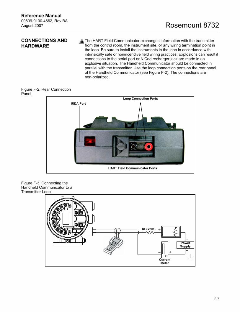
Reference Manual 00809-0100-4662, Rev BA
August 2007 Rosemount 8732
CONNECTIONS AND HARDWARE
The HART Field Communicator exchanges information with the transmitter from the control room, the instrument site, or any wiring termination point in the loop. Be sure to install the instruments in the loop in accordance with intrinsically safe or nonincendive field wiring practices. Explosions can result if connections to the serial port or NiCad recharger jack are made in an explosive situation. The Handheld Communicator should be connected in parallel with the transmitter. Use the loop connection ports on the rear panel of the Handheld Communicator (see Figure F-2). The connections are non-polarized.
Figure F-2. Rear Connection Panel
Figure F-3. Connecting the Handheld Communicator to a Transmitter Loop
IRDA Port
Loop Connection Ports
HART Field Communicator Ports
PowerSupply
Current Meter
RL≥250�
F-7
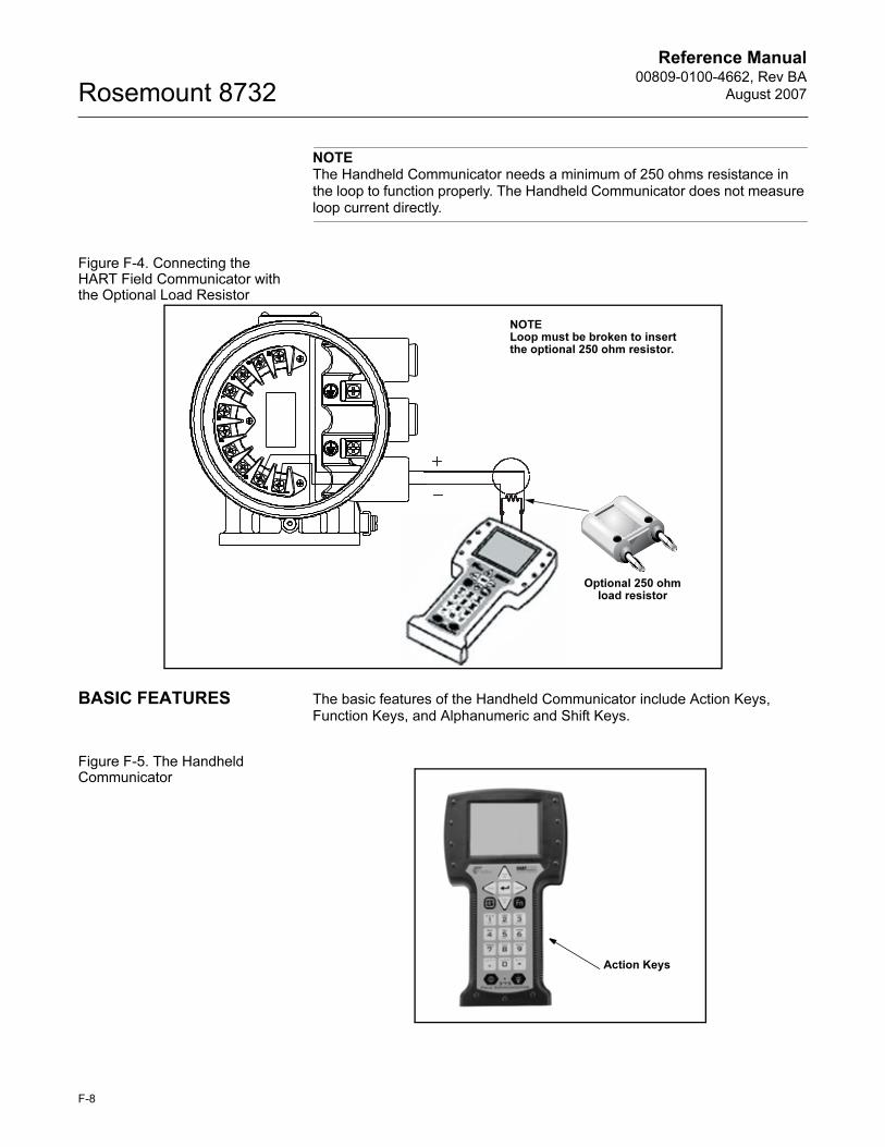
Reference Manual00809-0100-4662, Rev BA
August 2007Rosemount 8732
NOTEThe Handheld Communicator needs a minimum of 250 ohms resistance in the loop to function properly. The Handheld Communicator does not measure loop current directly.
Figure F-4. Connecting the HART Field Communicator with the Optional Load Resistor
BASIC FEATURES The basic features of the Handheld Communicator include Action Keys, Function Keys, and Alphanumeric and Shift Keys.
Figure F-5. The Handheld Communicator
NOTELoop must be broken to insert the optional 250 ohm resistor.
Optional 250 ohm load resistor
Action Keys
F-8
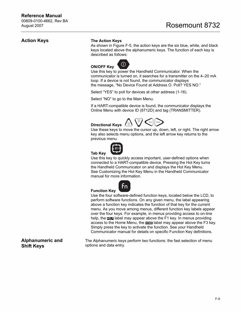
Reference Manual 00809-0100-4662, Rev BA
August 2007 Rosemount 8732
Action Keys The Action KeysAs shown in Figure F-5, the action keys are the six blue, white, and black keys located above the alphanumeric keys. The function of each key is described as follows:
ON/OFF Key Use this key to power the Handheld Communicator. When the communicator is turned on, it searches for a transmitter on the 4–20 mA loop. If a device is not found, the communicator displays the message, “No Device Found at Address O. Poll? YES NO.”
Select “YES” to poll for devices at other address (1-16).
Select “NO” to go to the Main Menu.
If a HART-compatible device is found, the communicator displays the Online Menu with device ID (8712D) and tag (TRANSMITTER).
Directional Keys Use these keys to move the cursor up, down, left, or right. The right arrow key also selects menu options, and the left arrow key returns to the previous menu.
Tab KeyUse this key to quickly access important, user-defined options whenconnected to a HART-compatible device. Pressing the Hot Key turnsthe Handheld Communicator on and displays the Hot Key Menu. See Customizing the Hot Key Menu in the Handheld Communicator manual for more information.
Function Key
Use the four software-defined function keys, located below the LCD, to perform software functions. On any given menu, the label appearing above a function key indicates the function of that key for the current menu. As you move among menus, different function key labels appear over the four keys. For example, in menus providing access to on-line help, the label may appear above the F1 key. In menus providing access to the Home Menu, the label may appear above the F3 key. Simply press the key to activate the function. See your Handheld Communicator manual for details on specific Function Key definitions.
Alphanumeric and Shift Keys
The Alphanumeric keys perform two functions: the fast selection of menu options and data entry.
PageUp
PageDn Bksp Delete
HELP
HOME
F-9
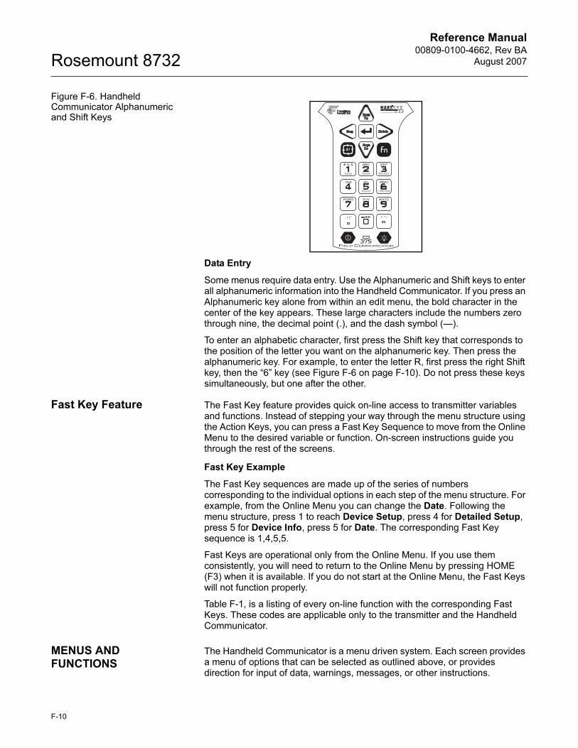
Reference Manual00809-0100-4662, Rev BA
August 2007Rosemount 8732
Figure F-6. Handheld Communicator Alphanumeric and Shift Keys
Data Entry
Some menus require data entry. Use the Alphanumeric and Shift keys to enter all alphanumeric information into the Handheld Communicator. If you press an Alphanumeric key alone from within an edit menu, the bold character in the center of the key appears. These large characters include the numbers zero through nine, the decimal point (.), and the dash symbol (—).
To enter an alphabetic character, first press the Shift key that corresponds to the position of the letter you want on the alphanumeric key. Then press the alphanumeric key. For example, to enter the letter R, first press the right Shift key, then the “6” key (see Figure F-6 on page F-10). Do not press these keys simultaneously, but one after the other.
Fast Key Feature The Fast Key feature provides quick on-line access to transmitter variables and functions. Instead of stepping your way through the menu structure using the Action Keys, you can press a Fast Key Sequence to move from the Online Menu to the desired variable or function. On-screen instructions guide you through the rest of the screens.
Fast Key Example
The Fast Key sequences are made up of the series of numbers corresponding to the individual options in each step of the menu structure. For example, from the Online Menu you can change the Date. Following the menu structure, press 1 to reach Device Setup, press 4 for Detailed Setup, press 5 for Device Info, press 5 for Date. The corresponding Fast Key sequence is 1,4,5,5.
Fast Keys are operational only from the Online Menu. If you use them consistently, you will need to return to the Online Menu by pressing HOME (F3) when it is available. If you do not start at the Online Menu, the Fast Keys will not function properly.
Table F-1, is a listing of every on-line function with the corresponding Fast Keys. These codes are applicable only to the transmitter and the Handheld Communicator.
MENUS AND FUNCTIONS
The Handheld Communicator is a menu driven system. Each screen provides a menu of options that can be selected as outlined above, or provides direction for input of data, warnings, messages, or other instructions.
F-10
Reference Manual 00809-0100-4662, Rev BA
August 2007 Rosemount 8732
Main Menu The Main Menu provides the following options:
• Offline - The Offline option provides access to offline configuration data and simulation functions.
• Online - The Online option checks for a device and if it finds one, brings up the Online Menu.
• Transfer - The Transfer option provides access to options for transferring data either from the Handheld Communicator (Memory) to the transmitter (Device) or vice versa. Transfer is used to move off-line data from the Handheld Communicator to the flowmeter, or to retrieve data from a flowmeter for off-line revision.
NOTEOnline communication with the flowmeter automatically loads the current flowmeter data to the Handheld Communicator. Changes in on-line data are made active by pressing SEND (F2). The transfer function is used only for off-line data retrieval and sending.
• Frequency Device - The Frequency Device option displays the frequency output and corresponding flow output of flow transmitters.
• Utility - The Utility option provides access to the contrast control for the Handheld Communicator LCD screen and to the autopoll setting used in multidrop applications.
Once selecting a Main Menu option, the Handheld Communicator provides the information you need to complete the operation. If further details are required, consult the Handheld Communicator manual.
Online Menu The Online Menu can be selected from the Main Menu as outlined above, or it may appear automatically if the Handheld Communicator is connected to an active loop and can detect an operating flowmeter.
NOTEThe Main Menu can be accessed from the Online Menu. Press the left arrow action key to deactivate the on-line communication with the flowmeter and to activate the Main Menu options.
When configuration variables are reset in the on-line mode, the new settings are not activated until the data are sent to the flowmeter. Press SEND (F2) to update the process variables of the flowmeter.
On-line mode is used for direct evaluation of a particular meter, re-configuration, changing parameters, maintenance, and other functions.
F-11
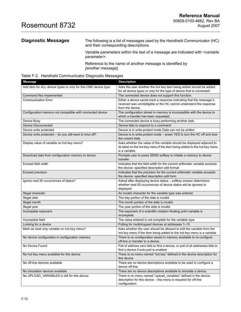
Reference Manual00809-0100-4662, Rev BA
August 2007Rosemount 8732
Diagnostic Messages The following is a list of messages used by the Handheld Communicator (HC) and their corresponding descriptions.
Variable parameters within the text of a message are indicated with <variable parameter>.
Reference to the name of another message is identified by [another message].
Table F-2. Handheld Communicator Diagnostic Messages
Message Description
Add item for ALL device types or only for this ONE device type Asks the user whether the hot key item being added should be added
for all device types or only for the type of device that is connected.
Command Not Implemented The connected device does not support this function.
Communication Error Either a device sends back a response indicating that the message it
received was unintelligible or the HC cannot understand the response
from the device.
Configuration memory not compatible with connected device The configuration stored in memory is incompatible with the device to
which a transfer has been requested.
Device Busy The connected device is busy performing another task.
Device Disconnected Device fails to respond to a command
Device write protected Device is in write-protect mode Data can not be written
Device write protected – do you still want to shut off? Device is in write-protect mode – press YES to turn the HC off and lose
the unsent data.
Display value of variable on hot key menu? Asks whether the value of the variable should be displayed adjacent to
its label on the hot key menu if the item being added to the hot key menu
is a variable.
Download data from configuration memory to device Prompts user to press SEND softkey to initiate a memory to device
transfer.
Exceed field width Indicates that the field width for the current arithmetic variable exceeds
the device- specified description edit format
Exceed precision Indicates that the precision for the current arithmetic variable exceeds
the device- specified description edit form
Ignore next 50 occurrences of status? Asked after displaying device status – softkey answer determines
whether next 50 occurrences of device status will be ignored or
displayed
Illegal character An invalid character for the variable type was entered.
Illegal date The day portion of the date is invalid.
Illegal month The month portion of the date is invalid.
Illegal year The year portion of the date is invalid.
Incomplete exponent The exponent of a scientific notation floating point variable is
incomplete.
Incomplete field The value entered is not complete for the variable type.
Looking for a device Polling for multidropped devices at addresses 1–15
Mark as read only variable on hot key menu? Asks whether the user should be allowed to edit the variable from the
hot key menu if the item being added to the hot key menu is a variable
No device configuration in configuration memory There is no configuration saved in memory available to re-configure
off-line or transfer to a device.
No Device Found Poll of address zero fails to find a device, or poll of all addresses fails to
find a device if auto-poll is enabled
No hot key menu available for this device There is no menu named “hot key” defined in the device description for
this device.
No off-line devices available There are no device descriptions available to be used to configure a
device off-line.
No simulation devices available There are no device descriptions available to simulate a device.
No UPLOAD_VARIABLES in ddl for this device There is no menu named “upload_variables” defined in the device
description for this device – this menu is required for off-line
configuration.
F-12
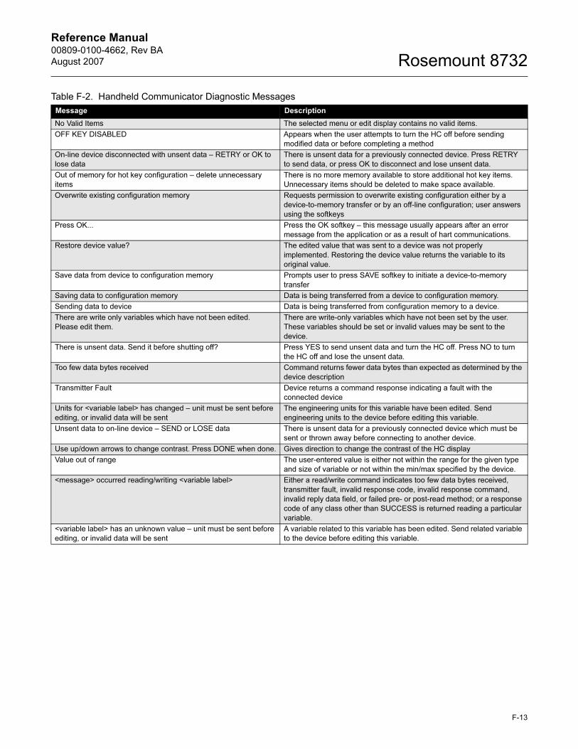
Reference Manual 00809-0100-4662, Rev BA
August 2007 Rosemount 8732
No Valid Items The selected menu or edit display contains no valid items.
OFF KEY DISABLED Appears when the user attempts to turn the HC off before sending
modified data or before completing a method
On-line device disconnected with unsent data – RETRY or OK to
lose data
There is unsent data for a previously connected device. Press RETRY
to send data, or press OK to disconnect and lose unsent data.
Out of memory for hot key configuration – delete unnecessary
items
There is no more memory available to store additional hot key items.
Unnecessary items should be deleted to make space available.
Overwrite existing configuration memory Requests permission to overwrite existing configuration either by a
device-to-memory transfer or by an off-line configuration; user answers
using the softkeys
Press OK... Press the OK softkey – this message usually appears after an error
message from the application or as a result of hart communications.
Restore device value? The edited value that was sent to a device was not properly
implemented. Restoring the device value returns the variable to its
original value.
Save data from device to configuration memory Prompts user to press SAVE softkey to initiate a device-to-memory
transfer
Saving data to configuration memory Data is being transferred from a device to configuration memory.
Sending data to device Data is being transferred from configuration memory to a device.
There are write only variables which have not been edited.
Please edit them.
There are write-only variables which have not been set by the user.
These variables should be set or invalid values may be sent to the
device.
There is unsent data. Send it before shutting off? Press YES to send unsent data and turn the HC off. Press NO to turn
the HC off and lose the unsent data.
Too few data bytes received Command returns fewer data bytes than expected as determined by the
device description
Transmitter Fault Device returns a command response indicating a fault with the
connected device
Units for <variable label> has changed – unit must be sent before
editing, or invalid data will be sent
The engineering units for this variable have been edited. Send
engineering units to the device before editing this variable.
Unsent data to on-line device – SEND or LOSE data There is unsent data for a previously connected device which must be
sent or thrown away before connecting to another device.
Use up/down arrows to change contrast. Press DONE when done. Gives direction to change the contrast of the HC display
Value out of range The user-entered value is either not within the range for the given type
and size of variable or not within the min/max specified by the device.
<message> occurred reading/writing <variable label> Either a read/write command indicates too few data bytes received,
transmitter fault, invalid response code, invalid response command,
invalid reply data field, or failed pre- or post-read method; or a response
code of any class other than SUCCESS is returned reading a particular
variable.
<variable label> has an unknown value – unit must be sent before
editing, or invalid data will be sent
A variable related to this variable has been edited. Send related variable
to the device before editing this variable.
Table F-2. Handheld Communicator Diagnostic Messages
Message Description
F-13

Reference Manual00809-0100-4662, Rev BA
August 2007Rosemount 8732
F-14
Reference Manual 00809-0100-4662, Rev BA
August 2007 Rosemount 8732
Index
AAccuracy . . . . . . . . . . . . . . . A-10
Rosemount 8705/8707 . . A-20Rosemount 8711 . . . . . . A-24
Action Keys
Handheld Communicator . F-9Alphanumeric Keys
Handheld Communicator . F-9Ambient Temperature . . . . . . A-12
Operating . . . . . . . . . . . . A-8Storage . . . . . . . . . . . . . A-8
Ambient Temperature Limits . . A-8Analog Output
Range . . . . . . . . . . . . . 3-10Zero . . . . . . . . . . . . . . . 3-10
Analog Output
Adjustment . . . . . . . A-3, A-8Analog Output Test . . . . A-4, A-9Analog Power . . . . . . . . . . . . 2-4Applications/Configurations . . . 2-4Auto Zero . . . . . . . . . . . . . . .D-2Auxiliary Output . . 2-13, A-4, A-9
BBasic Setup . . . . . . . . . . 3-6, 3-7Bolts
Flanged . . . . . . . . . . . . . 5-7
CCable Requirements for Remote
Transmitters . . . . . . . . . . . . . A-68Cables
Conduit . . . . . . . . 2-6, 2-17Calibration Number . . . . . . . 3-11Conductivity
Rosemount
8705/8707 . . . . . A-13, A-18Rosemount
8711 . . . . . . . . . . . . . . A-23Conduit Connections
Installation . . . . . . 2-6, 2-17Conduit Ports and Connections
Wiring . . . . . . . . . . . . . . 2-6Configurations/Applications . . . 2-4Connections
Handheld Communicator . F-7
Cover Gasket, Materials of
Construction . . . . . . . . . . . . A-12
DDamping . . . . . . . . . . .3-11, A-9Data Entry
Handheld Communicator F-10Dedicated Conduit . . . . . . . . 2-16Device Software Functions
Basic Setup . . . . . . .3-6, 3-7Diagnostic Messages . . . . . . . 6-3
Handheld Communicator F-12LOI . . . . . . . . . . . . . . . . 3-5
Digital Signal Processing . . . . D-1Direction . . . . . . . . . . . . . . . . 5-5Downstream/Upstream Piping 5-4
EElectrical
Considerations . . . . . . . . 2-7Electrical Connections . . . . . A-12Electrical Considerations . . . . 2-7Enclosure Ratings . . . . . . . . . A-8Environmental Considerations 2-3
FFailure Alarm Mode . . . . . . . . 2-4Fast Key
Feature . . . . . . . . . . . . F-10Fast Keys . . . . . . . . . . . . . . . F-2Flange Bolts . . . . . . . . . . . . . 5-7Flanges
Class 150 . . . . . . . . . . . 5-11Class 300 . . . . . . . . . . . 5-11
Flow Direction . . . . . . . . .5-5, 5-6Flow Rate
Units . . . . . . . . 3-7, 3-8, 3-9Flowtube
Connections . . . . . . . . . 2-16Orientation . . . . . . . . . . . 5-4Test . . . . . . . . . . . . . . . 6-10
Flowtube Compensation . . . A-10
Flowtubes
Brooks Model 5000 . . . . E-6Endress and
Hauser Models . . . . . . . . E-5Fischer and Porter
Model 10D1418 . . . . . . . E-8Foxboro Series 1800 . . E-15Generic Flowtube . . . . . E-26Kent Flowtubes . . . . . . E-20Kent Veriflux VTC . . . . . E-19Krohne Flowtubes . . . . E-21Rosemount
8705/8707/8711 . . . . . . . E-3Taylor Series 1100 . . . . E-22Yamatake Honeywell
Flowtubes . . . . . . . . . . E-24Yokogawa Flowtubes . . E-25
Function Keys
Handheld Communicator .F-9
GGaskets . . . . . . . . . . . . . . . . .5-7
Installation
Wafer Flowtube . . . .5-10Ground Connection
Internal . . . . . . . . . . . . .5-13Protective . . . . . . . . . . .5-13
Grounding . . . . . . . . . . . . . .5-12Grounding Electrodes . . .5-13Grounding Rings . . . . . .5-13Lining Protectors . . . . . .5-13Process Grounding . . . . .5-12
www.rosemount.com
Reference Manual00809-0100-4662, Rev BA
August 2007Rosemount 8732
HHandheld Communicator
Action Keys . . . . . . . . . . F-9Alphanumeric Keys . . . . . F-9Basic Features . . . . . . . . F-8Connections . . . . . . . . . . F-7Data Entry . . . . . . . . . . F-10Diagnostic Messages . . . F-12Function Keys . . . . . . . . . F-9Functions . . . . . . . . . . . F-10Hardware . . . . . . . . . . . . F-7Main Menu . . . . . . . . . . F-11Menu Tree . . . . . . . . . . . F-6Menus . . . . . . . . . . . . . F-10Online Menu . . . . . . . . . F-11Shift Keys . . . . . . . . . . . . F-9
Housing, Materials
of Construction . . . . . . . . . . A-12Humidity Limits . . . . . . . . . . . A-8
IInstallation
Auxiliary Output . . . . . . . 2-13Category . . . . . . . . . . . . 2-9Conduit Connections 2-6, 2-17Connect 4-20 mA
Loop External
Power Source . . . . . . . . 2-10Considerations . . . . . . . . 2-9Diagram
Cable Preparation . . 2-17Environmental
Considerations . . . . . . . . 2-3Flowtube Connections . . 2-16Mechanical
Considerations . . . . . . . . 2-2Mounting . . . . . . . . . . . . 2-3Options . . . . . . . . . . . . . 2-9Positive Zero Return . . . 2-14Procedures . . . . . . . . . . . 2-3Process Leak
Containment . . . . . . 5-17Relief Valves . . . . . . . . . 5-17Safety Messages . . . 2-1, 5-1Wafer Flowtube . . 5-10, 5-12
Alignment and Bolting 5-10Flange Bolts . . . . . . 5-11Gaskets . . . . . . . . . 5-10
Installation Category . . . . . . . . 2-9Internal
Ground Connection . . . . 5-13
LLine Power Fuses . . . . . . . . A-12Line Size . . . . . . . . . . . . . . . . 3-9Lining Protectors
Grounding . . . . . . . . . . 5-13Load Resistor Requirements . 2-11
Local Operator Interface (LOI)
Diagnostic Messages . . . 3-5Examples . . . . . . . . . . . . 3-2
Low Flow Cutoff . . . . . . . . . . A-9Lower Range Value (LRV) . . 3-10
MMaterials of Construction . . . A-12Maximum Power
Requirement . . . . . . . . . . . . 2-11Mechanical
Considerations . . . . . . . .2-2, 2-7Menu
Handheld Communicator F-10Tree . . . . . . . . . . . . . . . F-6
Messages
Safety . . . . . . . . . . . . . . 1-2Mounting . . . . . . . . . . . . . . . 2-3
Rosemount
8705/8707 . . . . . A-15, A-20Rosemount
8711 . . . . . . . . . . . . . . A-24
NNiCad Recharger . . . . . . . . . F-7North American
Response Center . . . . . . . . . 1-2
OOptions . . . . . . . . . . . . . . . . 2-4Orientation
Flowtube . . . . . . . . . . . . 5-4Output
Power . . . . . . . . . . . . . . 2-4Output Signals . . . . . . . A-3, A-8Output Testing . . . . . . . A-4, A-9Overcurrent Protection . . . . . . 2-9Overrange Capability . . . A-4, A-9
PPaint, Materials of
Construction . . . . . . . . . . . . A-12Performance Specifications . A-10Physical Specifications . . . . A-12Piping . . . . . . . . . . . . . . . . . 5-4Positive Zero Return . . 2-14, A-9Power
Source . . . . . . . . . . . . . 2-10Power Supply Load
Limitations . . . . . . . . . . A-2, A-7Pressure
Rosemount
8705/8707 . . . . . . . . . . A-17Rosemount
8711 . . . . . . . . . . . . . . A-23Process Grounding . . . . . . . 5-12
Process Leak
Containment . . . . . . . . .5-17Process Variables . . . . . . . . . .3-5Protection
Overcurrent . . . . . . . . . . .2-9Protective
Ground Connection . . . .5-13Pulse Duration
Requirements . . . . . . . . . . . . 2-11Pulse Output Test . . . . . .A-4, A-9PZR . . . . . . . . . . . . . . . . . .2-14
RRelief Valves . . . . . . . . . . . .5-17Remote Transmitters
Cable requirements . . . A-68Repeatability . . . . . . . . . . . A-10Response Time . . . . . . . . . .A-11RFI Effect . . . . . . . . . . . . . A-12
SSafety Messages . . . . . . . . . .1-2Scalable Frequency
Adjustment . . . . . . . . . . .A-4, A-9Security . . . . . . . . . . . . . . . . .2-5Shift Keys
Handheld Communicator .F-9Signal Processing . . . . . . . . . D-2Software
lockout . . . . . . . . . . . . . A-9
Index-2
Reference Manual00809-0100-4662, Rev BA
August 2007 Rosemount 8732
Specifications
Rosemount 8705 and
Rosemount 8707
accuracy . . . . . . . . A-20ambient temperature
limits . . . . . . . . . . . A-17ASME/ANSI . . . . . . A-21conductivity
limits . . . . . . A-13, A-18electrical
connections . . . . . . A-21electrodes . . . . . . . A-20functional
specifications . . . . . A-17grounding
electrode . . . . . . . . A-21grounding rings . . . . A-21interchangeability . . A-17line sizes . . . . . . . . A-17lining . . . . . . . . . . . A-20lining protectors . . . A-21mounting position
effect . . . . . . A-15, A-20non-wetted
materials . . . . . . . . A-20performance
specifications . . . . . A-19physical specifications A-20pressure limits . . . . A-17process conditions . A-21process temperature
limits . . . . . . . . . . . A-17process wetted
materials . . . . . . . . A-20service . . . . . . . . . . A-17submergence
protection . . . . . . . . A-17upper range limit . . . A-17vacuum limits . . . . . A-17vibration effect . . . . A-20weight . . . . . . . . . . A-21
Rosemount 8711
accuracy . . . . . . . . A-24ambient temperature
limits . . . . . . . . . . . A-23conductivity limits . . A-23electrodes . . . . . . . A-24functional specifications A-23interchangeability . . A-23line sizes . . . . . . . . A-23lining . . . . . . . . . . . A-24mounting position
effect . . . . . . . . . . A-24non-wetted materials A-24performance
specifications . . . . . A-24physical
specifications . . . . . A-24process conditions . A-25process temperature
limits . . . . . . . . . . . A-23process-wetted
materials . . . . . . . . A-24safe working pressure A-23service . . . . . . . . . A-23upper range limit . . A-23vibration effect . . . . A-24
Specifications and Reference Data
Functional Specifications
Ambient Temperature
Limits . . . . . . . . . . . A-8Conductivity Limits . . A-7Damping . . . . . . . . . A-9Enclosure Ratings . . A-8Flow Rate Range . . . A-7Flowtube Coil
Resistance . . . . . . . A-7Flowtube
Compatibility . . . . . . A-7Flowtube
Compensation . . . . A-10Humidity Limits . . . . A-8Installation Coordination A-8Low Flow Cutoff . . . . A-9Output Signals . A-3, A-8Output Testing . A-4, A-9Overrange
Capability . . . . A-4, A-9Positive Zero Returns A-9Power Consumption . A-8Power Supply . . . . . A-7Software Lockout . . . A-9Start-up Time . . . . . . A-9Turn-on Time . . . . . . A-9
Performance Specifications A-10Accuracy . . . . . . . A-10Ambient Temperature
Effect . . . . . . . . . . A-12Repeatability . . . . . A-10Response Time . . . .A-11RFI Effect . . . . . . . A-12Stability . . . . . . . . .A-11Supply Voltage Effect A-12Vibration Effect . . . A-10
Physical Specifications . A-12Cable Requirements for
Remote Transmitters
. . . . . . . . A-68Electrical Connections A-12Line Power Fuses . A-12Materials of
Construction . . . . . A-12Stability . . . . . . . . . . . . . . . .A-11Start-up Time . . . . . . . . . . . . A-9Storage . . . . . . . . . . . . . . . . A-8Supply Voltage
Requirements . . . . . . . . 2-11Supply Voltage Effect . . . . . A-12Switches . . . . . . . . . . . . . . . .2-4
Changing Settings . . . . . .2-5Closure Requirements . . 2-11Failure Alarm Mode . . . . .2-4
TTag . . . . . . . . . . . . . . . . . . . .3-7Temperature . . . . . . . . . . . . A-8
Rosemount
8705/8707 . . . . . . . . . . A-17Rosemount
8711 . . . . . . . . . . . . . . A-23Transmitter Output Instability
Auto Zero . . . . . . . . . . . D-2Procedures . . . . . . . . . . D-2Signal Processing . . . . . D-2
Transmitter Security . . . . . . . .2-5Transporting System . . . . . . . .5-3Troubleshooting
Advanced (Transmitter) . .6-7Installed Flowtube Tests .6-10Process Noise . . . . . . . . .6-9Uninstalled Flowtube Tests 6-11Wiring Errors . . . . . . . . . .6-9
Turn-on Time . . . . . . . . . . . . A-9
UUpper Range Value (URV) . .3-10Upstream/Downstream Piping .5-4
Accuracy
Ensuring . . . . . . . . . .5-4
Index-3
Reference Manual00809-0100-4662, Rev BA
August 2007Rosemount 8732
VVCR . . . . . . . . . . . . . . . . . . A-14Vibration
Rosemount
8705/8707 . . . . . . . . . . A-20Rosemount
8711 . . . . . . . . . . . . . . A-24Vibration Effect . . . . . . . . . . A-10
WWeight . . . . . . . . . . . . . . . . A-12
Rosemount
8705/8707 . . . . . . . . . . A-21Wiring
Conduit Ports and
Connections . . . . . . . . . . 2-6Dedicated Conduit . . . . . 2-16Installation Category . . . . 2-9
Wiring Diagrams
Brooks Rosemount 5000 . E-6Endress and Hauser
Models . . . . . . . . . . . . . . E-5Fisher and Porter
Model 10D1418 . . . . . . . . E-8Foxboro Series 1800 . . . E-15Generic Flowtube . . . . . E-26Kent Flowtubes . . . . . . . E-20Kent Verifulx VTC . . . . . E-19Krohne Flowtubes . . . . . E-21Rosemount
8705/8707/8711 . . . . . . . E-3Taylor Series 1100 . . . . E-22Yamatake Honeywell
Flowtubes . . . . . . . . . . . E-24Yokogawa Flowtubes . . . E-25
Index-4


Reference Manual00809-0100-4662, Rev AA
August 2007
Emerson Process Management
© 2007 Rosemount Inc. All rights reserved.
¢00809-XXXX-XXXX ¤
The Emerson logo is a trade mark and service mark of Emerson Electric Co.Rosemount and the Rosemount logotype are registered trademarks of Rosemount Inc.PlantWeb is a registered trademark of one of the Emerson Process Management group of companies.All other marks are the property of their respective owners.
Rosemount Temperature GmbHNeonstraat 1 6718 WX EdeThe Netherlands T +31 (0)318 495555F +31(0) 318 495556
Emerson Process Management Asia Pacific Private Limited1 Pandan CrescentSingapore 128461T (65) 6777 8211F (65) 6777 [email protected]
Rosemount Divison8200 Market BoulevardChanhassen, MN 55317 USAT (U.S.) 1-800-999-9307T (International) (952) 906-8888F (952) 949-7001
www.rosemount.com
Recommended


![AXR Two-wire Magnetic Flowmeter Integral Flowmeter [Style:S2]](https://img.pdfslide.us/doc/110x75/62cb14e07ee31d38b74d3e5b/axr-two-wire-magnetic-flowmeter-integral-flowmeter-styles2.jpg)