1
Milenko Prţulj 1)
INTEGRAL CONCRETE BRIDGES
SUMMARY:
Integral bridges are concrete bridges consisting of a frame structure without any expansion joints and
bearings. The integral bridges are constructed monolithically, and the dimensions of structural load
bearing elements are more abundant. Damages to such bridges are less intensive due to elimination of
the main sources of damages, i.e. discontinuity areas, expansion joints, and bearing zones. The
maintenance costs are lower, and the traffic is safer. Frame structures contain system reserves in both
load distribution and static actions.
A bridge design in accordance with rules and codes is not a sufficient guaranty for a good and durable
bridge. A correct conception is required taking into consideration experiences of practice and
information gained from bridge maintenance and management.
The paper includes the following chapters: introduction, delusions in the field of prefabricated
structures, damages to concrete bridges, beam and frame concrete bridges, concepts of integral
bridges, constructive details of integral bridges, and analysis of integral bridges.
1. INTRODUCTION
On the actual roads there are numerous bridges of small and medium spans, which essentially affect
the construction time and costs. Individual solving of such bridges according to subjective inclinations
and the level of both knowledge and experience of design engineers is a history. The construction
economy, time and technology require that groups of bridges are designed and constructed as a whole.
The field of activity is to search for optimum bearing structures where maximum possible resistance
and durability of a bridge as an utilizable structure can be achieved by proper amount of both material
and work. Such a task which seems to be simple is complex and functionally conditioned.
In the bridge construction, prestressing of reinforced concrete has been developing in the filed of beam
systems of bearing structures. This is completely understandable as both bending and tension are such
states of stress, which do not correspond to the natural properties of the concrete as construction
material.
The prestressing has been developing in two directions: in the direction of mastering large span
bridges, which had been out of reach for the reinforced concrete, and in the direction of development
of construction technologies.
From among static systems, a beam on two supports spanning between 15 and 50 m, as well as
continuous and frame systems of bearing structures are mostly used.
As the development and the application of unified steel falsework and other equipment for cast-in-situ
concreting had fallen behind, the reinforced concrete lost its competitiveness in view of the
prefabricated element construction even in structures where it is objectively advantageous.
Uncritical acceptance of all the advantages and innovations that had arisen with prestressing of the
reinforced concrete, led to the decrease of both bearing capacity and durability ob structures, as well as
to significant costs related to the rehabilitation of endangered bridge bearing structures.
___________________________________________________ 1) Prof. Dr., Consultant, DDC Consulting and Engineering, Ljubljana, Slovenia
2
A delusion that reinforced concrete structures need not be maintained, as though durable materials are
in question, has also been transferred to bearing structures made of prestressed reinforced concrete.
Such a wrong opinion has been emphasized for a long time as basic advantage in comparison with
other construction materials.
Visible damages to bearing structures of bridges and frequent failures and destructions have drawn
attention of professional publicity to inspection of constructed bridges, to gathering and selecting
relevant information, as well as to creating informational systems on executed bridges. Now, bridge
designers have opportunity to participate in bridge inspections and to use the gained information
efficiently. In such a way it is possible to have influence on the change of present situation as well as
of progress and innovations.
2. DELUSIONS IN THE FIELD OF PREFABRICATED STRUCTURES
Structures made of prefabricated (precast) reinforced concrete elements are positively advantageous in
the construction of industrial, public, and residential buildings, provided that they are based on
verified and adequate constructive and technological solutions. The construction method based on
prefabricated elements has certain advantages in the filed of bridges as well, however some potential
risks can be encountered if both exploitation and climatic conditions are not taken into account.
A load bearing structure made of prestressed reinforced concrete can be assessed as successful if an
optimum amount of material, work, and construction time has been achieved.
On the basis of continuous monitoring of bridge behaviour during the service life, of detailed
professional inspections during the preparation of appropriate bridge informational systems, as well as
of published comprehensions, certain common features can be summarized, and useful ideas to
eliminate deficiencies noticed and to improve constructive solutions of bridge bearing structures can
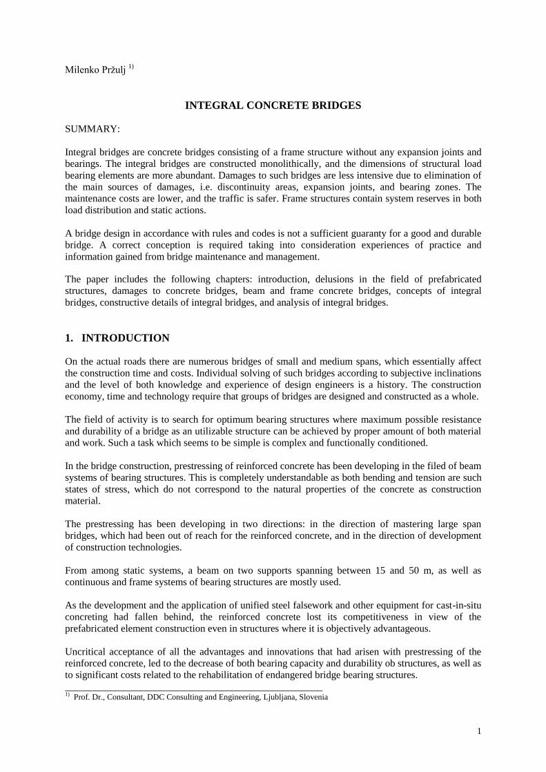
be provided. All the schemes of bridge load bearing structures made of prefabricated prestressed
reinforced concrete elements contain longitudinal joints between precast girders (Fig. 1). A monolithic
structure created only by cross connections above the bridge supports is insufficient to ensure a
collective work of all structural members during the bridge service life. LONGITUDINAL JOINTS
Fig. 1
After longer service and fatigue of the longitudinal hinge connection, such solutions may lead to
longitudinal cracks through which the water can seep. So the way is clear for destruction of the load
bearing structure. The thickness of the upper slab amounting to 15 cm is insufficient to ensure safety
against punching due to vehicle wheel impact, particularly in conditions of uneven and damaged
carriageways.
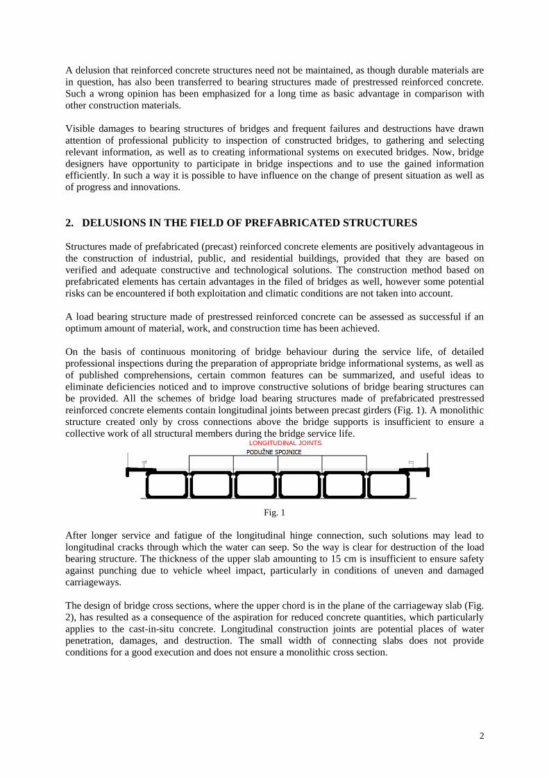
The design of bridge cross sections, where the upper chord is in the plane of the carriageway slab (Fig.
2), has resulted as a consequence of the aspiration for reduced concrete quantities, which particularly
applies to the cast-in-situ concrete. Longitudinal construction joints are potential places of water
penetration, damages, and destruction. The small width of connecting slabs does not provide
conditions for a good execution and does not ensure a monolithic cross section.
3
CAST-IN-SITU SLAB PORTION
PREFABRICATED GIRDERS I Fig. 2
Attempts to execute the reinforced concrete carriageway slab above the main prefabricated girders as a
prefabricated slab have not ensured the bridge durability, especially in severe climatic conditions as
well as on roads with high traffic intensity. Already after 10 years, detailed reconstructions were
indispensable, which has led to administrative interdiction of such solutions.
A monolithic effect, i.e. co-acting of prefabricated girders within the bearing structure cross section, as
well as the bridge durability, can be ensured by designing such cross sections (Fig. 3) where the
carriageway slab is cast in situ above the upper chord of already erected main girders, thus forming a
unified composite cross section. Concreting of the slab is simple, since no falsework is required. A
possibility of use for oblique and curved bridges, as well as of neutralizing geometrical errors is
enabled.
Fig. 3
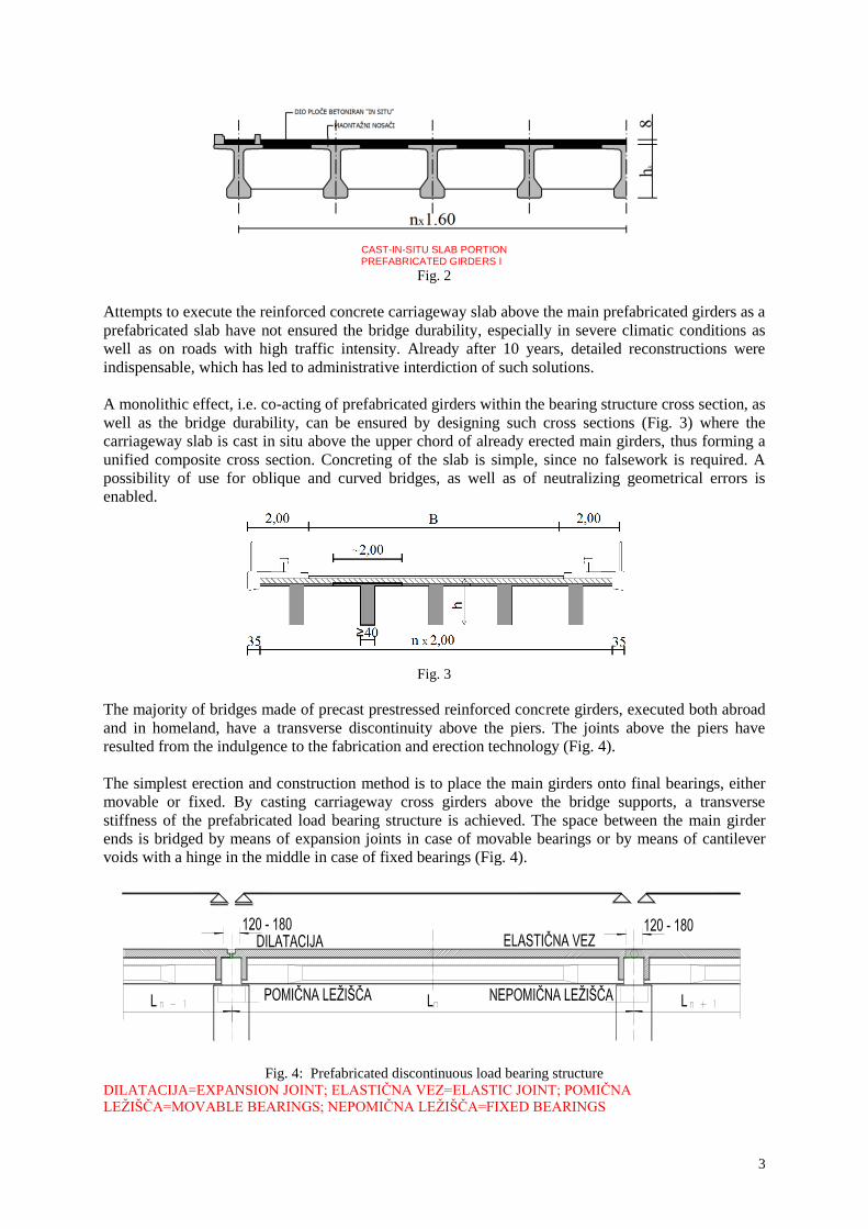
The majority of bridges made of precast prestressed reinforced concrete girders, executed both abroad
and in homeland, have a transverse discontinuity above the piers. The joints above the piers have
resulted from the indulgence to the fabrication and erection technology (Fig. 4).
The simplest erection and construction method is to place the main girders onto final bearings, either
movable or fixed. By casting carriageway cross girders above the bridge supports, a transverse
stiffness of the prefabricated load bearing structure is achieved. The space between the main girder
ends is bridged by means of expansion joints in case of movable bearings or by means of cantilever
voids with a hinge in the middle in case of fixed bearings (Fig. 4).
Fig. 4: Prefabricated discontinuous load bearing structure
DILATACIJA=EXPANSION JOINT; ELASTIČNA VEZ=ELASTIC JOINT; POMIČNA
LEŢIŠČA=MOVABLE BEARINGS; NEPOMIČNA LEŢIŠČA=FIXED BEARINGS
4
3. DAMAGES TO CONCRETE BRIDGES
Damages to concrete bridges can result from the following factors:
- structural deficiencies of bridge load bearing structure and equipment,
- corrosion of both reinforcement and tendons,
- aggressive action of chemical compounds (chloride and other aggressiveness of environment),
- damages due to low temperatures (freezing),
- processes within the reinforced concrete structure,
- prevented displacements,
- mechanical actions - damages,
- occurrence of cracks in concrete structures.
Structural deficiencies of bridge load bearing structures and equipment are consequence of the
following:
- bridge structure design in view of its arrangement and static scheme,
- false solutions of constructive details,
- incorrect solutions of bridge equipment (bearings, expansion joints, waterproofing, asphalt
carriageway, barriers, dewatering),
- unsuitably selected construction methods, precast or semi-precast construction with
discontinuities and joints on the carriageway slab,
- adequate choice and poor quality of materials,
- absence of permanent protection and maintenance of bridges.
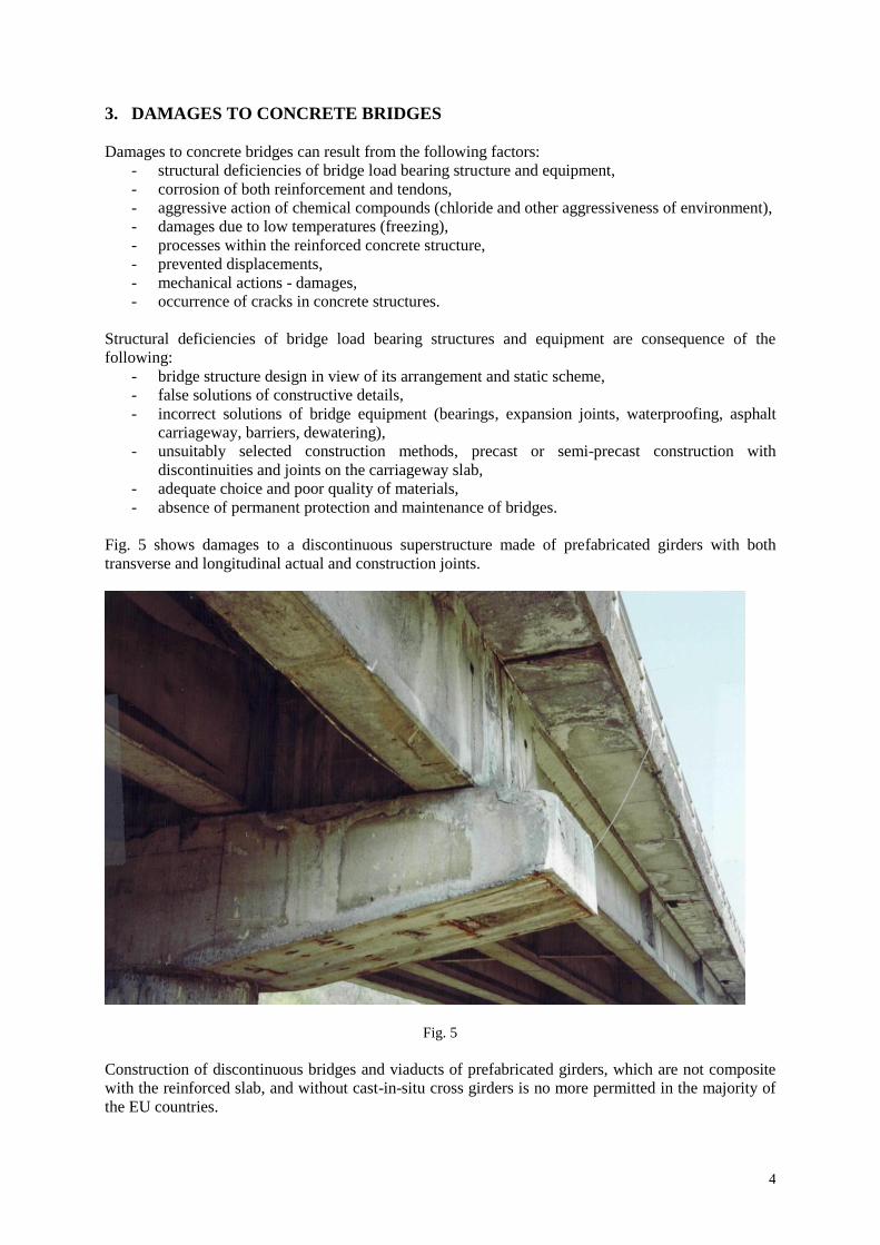
Fig. 5 shows damages to a discontinuous superstructure made of prefabricated girders with both
transverse and longitudinal actual and construction joints.
Fig. 5
Construction of discontinuous bridges and viaducts of prefabricated girders, which are not composite
with the reinforced slab, and without cast-in-situ cross girders is no more permitted in the majority of
the EU countries.
5
Other causes of damages to concrete bridges will not be discussed hereinafter, as this is not within the
topic of the present paper.
4. BEAM AND FRAME BRIDGES
From among five known load bearing systems (beam, frame, arched, suspension, and cable stayed),
beam bridges are most frequently constructed. The majority of all the executed bridges belong to
concrete beam bridges.
The span length, total length, cross section design, method of supporting, and transfer of actions from
the superstructure to supports, as well as the construction technology have been changing during more
than 100 years of concrete bridge development.
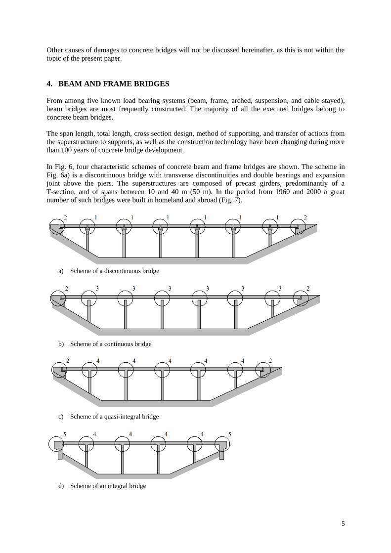
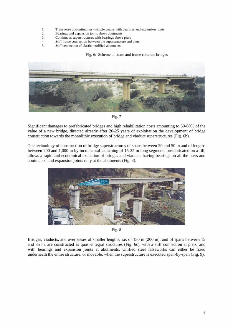
In Fig. 6, four characteristic schemes of concrete beam and frame bridges are shown. The scheme in
Fig. 6a) is a discontinuous bridge with transverse discontinuities and double bearings and expansion
joint above the piers. The superstructures are composed of precast girders, predominantly of a
T-section, and of spans between 10 and 40 m (50 m). In the period from 1960 and 2000 a great
number of such bridges were built in homeland and abroad (Fig. 7).
a) Scheme of a discontinuous bridge
b) Scheme of a continuous bridge
c) Scheme of a quasi-integral bridge
d) Scheme of an integral bridge
6
1. Transverse discontinuities - simple beams with bearings and expansion joints
2. Bearings and expansion joints above abutments
3. Continuous superstructures with bearings above piers
4. Stiff frame connection between the superstructure and piers
5. Stiff connection of elastic modified abutments
Fig. 6: Scheme of beam and frame concrete bridges
Fig. 7
Significant damages to prefabricated bridges and high rehabilitation costs amounting to 50-60% of the
value of a new bridge, directed already after 20-25 years of exploitation the development of bridge
construction towards the monolithic execution of bridge and viaduct superstructures (Fig. 6b).
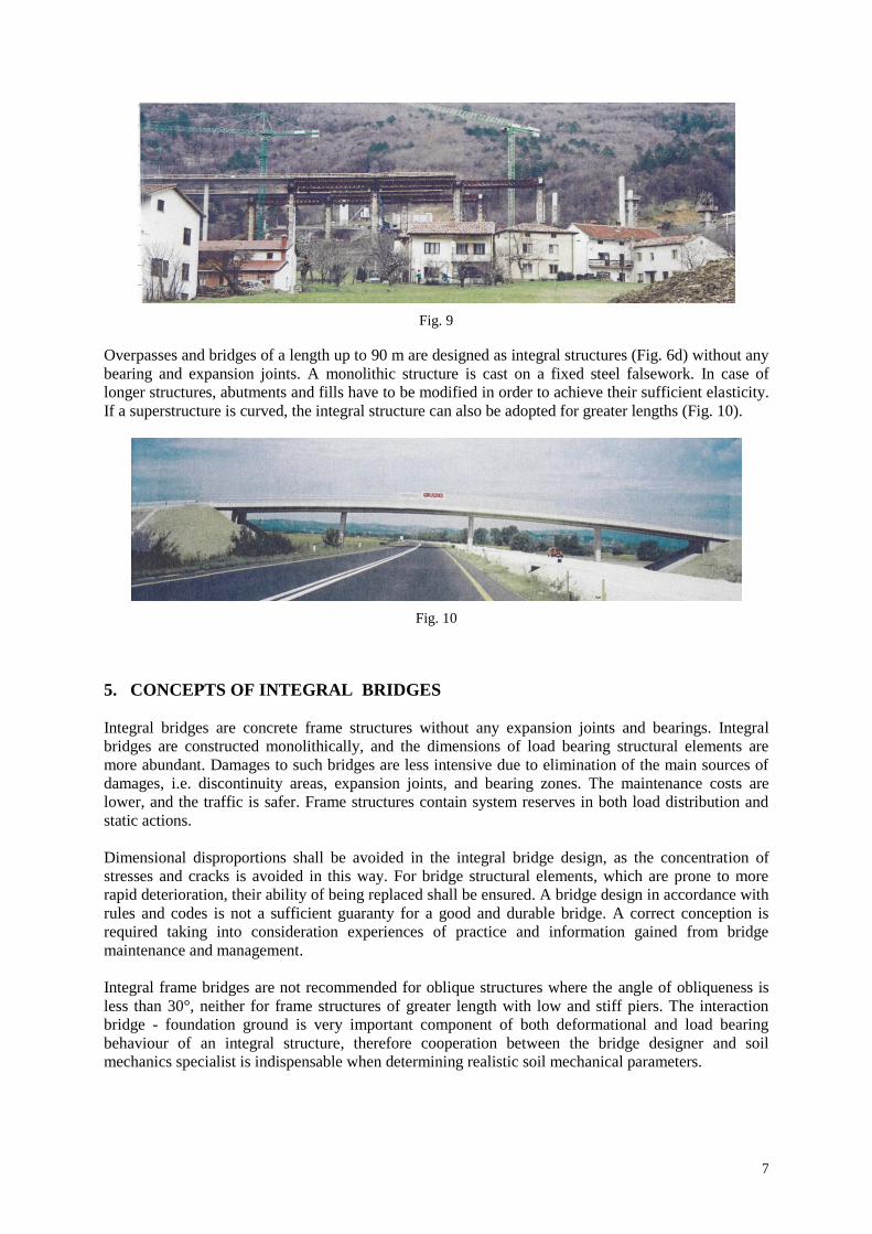
The technology of construction of bridge superstructures of spans between 20 and 50 m and of lengths
between 200 and 1,000 m by incremental launching of 15-25 m long segments prefabricated on a fill,
allows a rapid and economical execution of bridges and viaducts having bearings on all the piers and
abutments, and expansion joints only at the abutments (Fig. 8).
Fig. 8
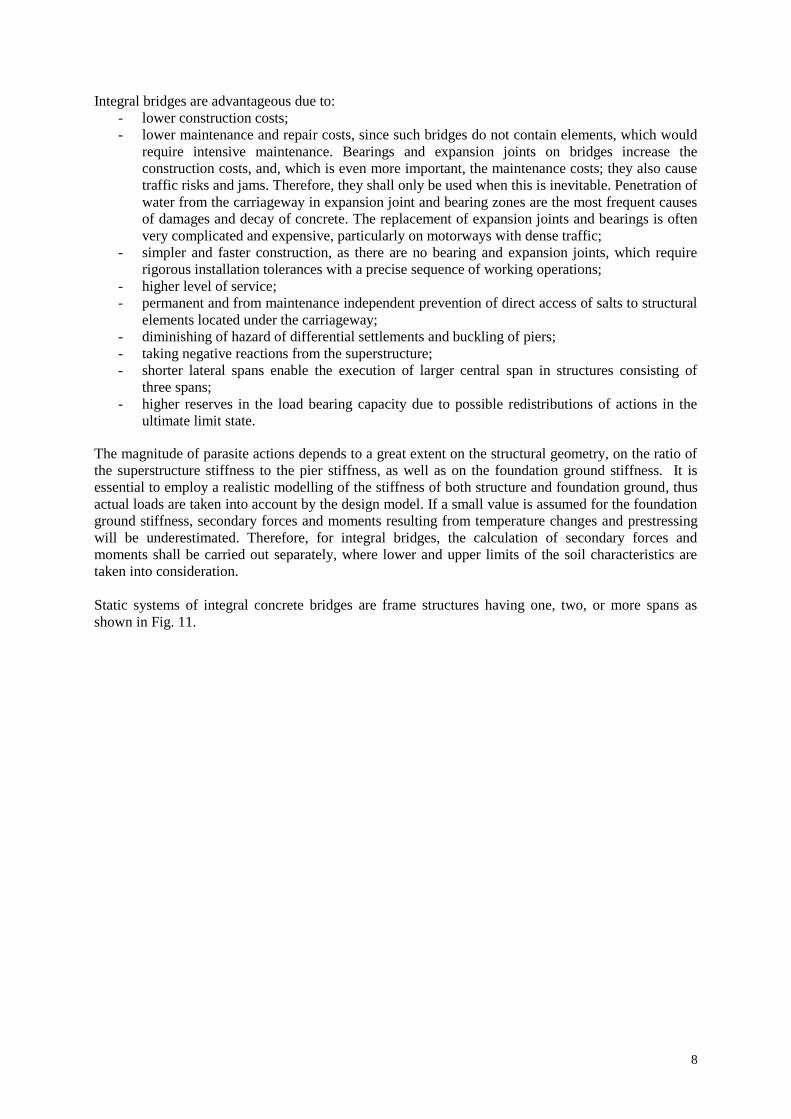
Bridges, viaducts, and overpasses of smaller lengths, i.e. of 150 m (200 m), and of spans between 15
and 35 m, are constructed as quasi-integral structures (Fig. 6c), with a stiff connection at piers, and
with bearings and expansion joints at abutments. Unified steel falseworks can either be fixed
underneath the entire structure, or movable, when the superstructure is executed span-by-span (Fig. 9).
7
Fig. 9
Overpasses and bridges of a length up to 90 m are designed as integral structures (Fig. 6d) without any
bearing and expansion joints. A monolithic structure is cast on a fixed steel falsework. In case of
longer structures, abutments and fills have to be modified in order to achieve their sufficient elasticity.
If a superstructure is curved, the integral structure can also be adopted for greater lengths (Fig. 10).
Fig. 10
5. CONCEPTS OF INTEGRAL BRIDGES
Integral bridges are concrete frame structures without any expansion joints and bearings. Integral
bridges are constructed monolithically, and the dimensions of load bearing structural elements are
more abundant. Damages to such bridges are less intensive due to elimination of the main sources of
damages, i.e. discontinuity areas, expansion joints, and bearing zones. The maintenance costs are
lower, and the traffic is safer. Frame structures contain system reserves in both load distribution and
static actions.
Dimensional disproportions shall be avoided in the integral bridge design, as the concentration of
stresses and cracks is avoided in this way. For bridge structural elements, which are prone to more
rapid deterioration, their ability of being replaced shall be ensured. A bridge design in accordance with
rules and codes is not a sufficient guaranty for a good and durable bridge. A correct conception is
required taking into consideration experiences of practice and information gained from bridge
maintenance and management.
Integral frame bridges are not recommended for oblique structures where the angle of obliqueness is
less than 30°, neither for frame structures of greater length with low and stiff piers. The interaction
bridge - foundation ground is very important component of both deformational and load bearing
behaviour of an integral structure, therefore cooperation between the bridge designer and soil
mechanics specialist is indispensable when determining realistic soil mechanical parameters.
8
Integral bridges are advantageous due to:
- lower construction costs;
- lower maintenance and repair costs, since such bridges do not contain elements, which would
require intensive maintenance. Bearings and expansion joints on bridges increase the
construction costs, and, which is even more important, the maintenance costs; they also cause
traffic risks and jams. Therefore, they shall only be used when this is inevitable. Penetration of
water from the carriageway in expansion joint and bearing zones are the most frequent causes
of damages and decay of concrete. The replacement of expansion joints and bearings is often
very complicated and expensive, particularly on motorways with dense traffic;
- simpler and faster construction, as there are no bearing and expansion joints, which require
rigorous installation tolerances with a precise sequence of working operations;
- higher level of service;
- permanent and from maintenance independent prevention of direct access of salts to structural
elements located under the carriageway;
- diminishing of hazard of differential settlements and buckling of piers;
- taking negative reactions from the superstructure;
- shorter lateral spans enable the execution of larger central span in structures consisting of
three spans;
- higher reserves in the load bearing capacity due to possible redistributions of actions in the
ultimate limit state.
The magnitude of parasite actions depends to a great extent on the structural geometry, on the ratio of
the superstructure stiffness to the pier stiffness, as well as on the foundation ground stiffness. It is
essential to employ a realistic modelling of the stiffness of both structure and foundation ground, thus
actual loads are taken into account by the design model. If a small value is assumed for the foundation
ground stiffness, secondary forces and moments resulting from temperature changes and prestressing
will be underestimated. Therefore, for integral bridges, the calculation of secondary forces and
moments shall be carried out separately, where lower and upper limits of the soil characteristics are
taken into consideration.
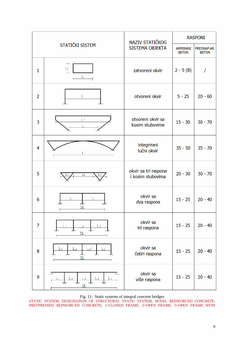
Static systems of integral concrete bridges are frame structures having one, two, or more spans as
shown in Fig. 11.
9
Fig. 11: Static systems of integral concrete bridges
STATIC SYSTEM, DESIGNATION OF STRUCTURAL STATIC SYSTEM, SPANS, REINFORCED CONCRETE,
PRESTRESSED REINFORCED CONCRETE, 1=CLOSED FRAME; 2=OPEN FRAME, 3=OPEN FRAME WITH
10
INCLINED PIERS; 4=INTEGRATED ARCH FRAME, 5=THREE-SPAN FRAME WITH INCLINED PIERS, 6=TWO-
SPAN FRAME, 7=THREE-SPAN FRAME, 8=FOUR-SPAN FRAME, 9=MULTI-SPAN FRAME
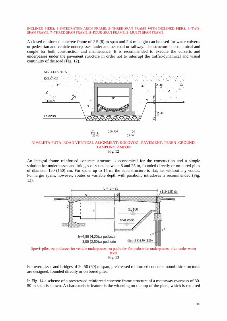
A closed reinforced concrete frame of 2-5 (8) m span and 2-4 m height can be used for water culverts
or pedestrian and vehicle underpasses under another road or railway. The structure is economical and
simple for both construction and maintenance. It is recommended to execute the culverts and
underpasses under the pavement structure in order not to interrupt the traffic-dynamical and visual
continuity of the road (Fig. 12).
NIVELETA PUTA=ROAD VERTICAL ALIGNMENT; KOLOVOZ =PAVEMENT, TEREN=GROUND,
TAMPON=TAMPON
Fig. 12
An integral frame reinforced concrete structure is economical for the construction and a simple
solution for underpasses and bridges of spans between 8 and 25 m, founded directly or on bored piles
of diameter 120 (150) cm. For spans up to 15 m, the superstructure is flat, i.e. without any voutes.
For larger spans, however, voutes or variable depth with parabolic intradoses is recommended (Fig.
13).
šipovi=piles; za podvoze=for vehicle underpasses; za podhode=for pedestrian underpasses; nivo vode=water
level
Fig. 13
For overpasses and bridges of 20-50 (60) m span, prestressed reinforced concrete monolithic structures
are designed, founded directly or on bored piles.
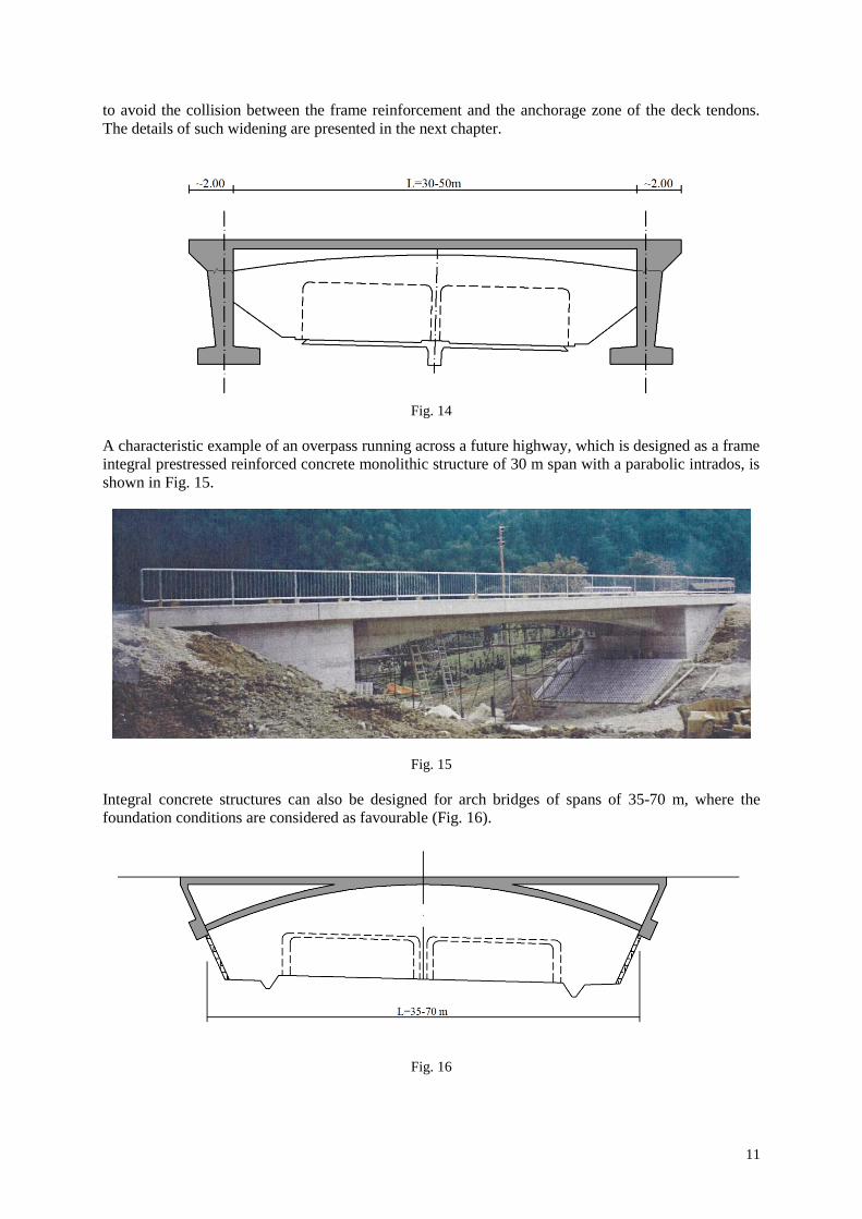
In Fig. 14 a scheme of a prestressed reinforced concrete frame structure of a motorway overpass of 30-
50 m span is shown. A characteristic feature is the widening on the top of the piers, which is required
11
to avoid the collision between the frame reinforcement and the anchorage zone of the deck tendons.
The details of such widening are presented in the next chapter.
Fig. 14
A characteristic example of an overpass running across a future highway, which is designed as a frame
integral prestressed reinforced concrete monolithic structure of 30 m span with a parabolic intrados, is
shown in Fig. 15.
Fig. 15
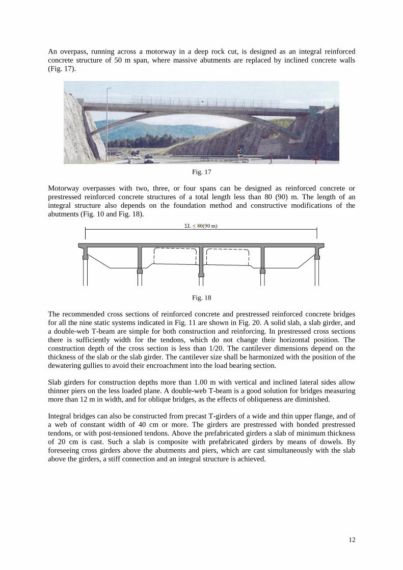
Integral concrete structures can also be designed for arch bridges of spans of 35-70 m, where the
foundation conditions are considered as favourable (Fig. 16).
Fig. 16
12
An overpass, running across a motorway in a deep rock cut, is designed as an integral reinforced
concrete structure of 50 m span, where massive abutments are replaced by inclined concrete walls
(Fig. 17).
Fig. 17
Motorway overpasses with two, three, or four spans can be designed as reinforced concrete or
prestressed reinforced concrete structures of a total length less than 80 (90) m. The length of an
integral structure also depends on the foundation method and constructive modifications of the
abutments (Fig. 10 and Fig. 18).
Fig. 18
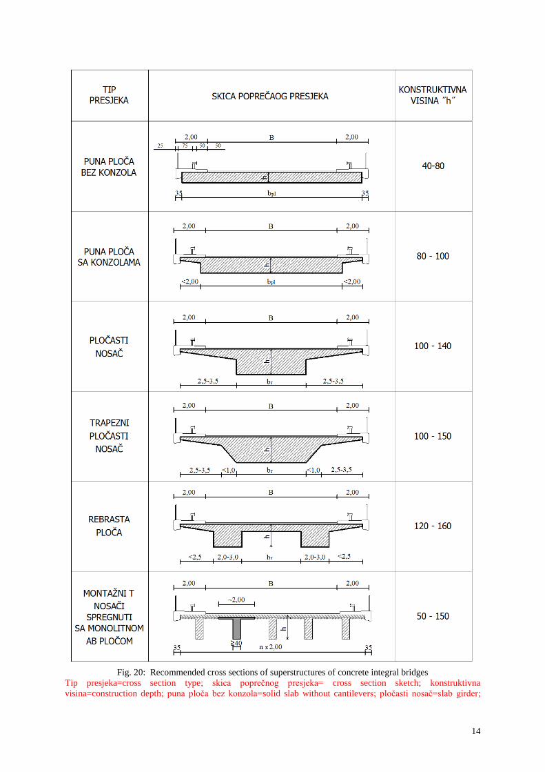
The recommended cross sections of reinforced concrete and prestressed reinforced concrete bridges
for all the nine static systems indicated in Fig. 11 are shown in Fig. 20. A solid slab, a slab girder, and
a double-web T-beam are simple for both construction and reinforcing. In prestressed cross sections
there is sufficiently width for the tendons, which do not change their horizontal position. The
construction depth of the cross section is less than 1/20. The cantilever dimensions depend on the
thickness of the slab or the slab girder. The cantilever size shall be harmonized with the position of the
dewatering gullies to avoid their encroachment into the load bearing section.
Slab girders for construction depths more than 1.00 m with vertical and inclined lateral sides allow
thinner piers on the less loaded plane. A double-web T-beam is a good solution for bridges measuring
more than 12 m in width, and for oblique bridges, as the effects of obliqueness are diminished.
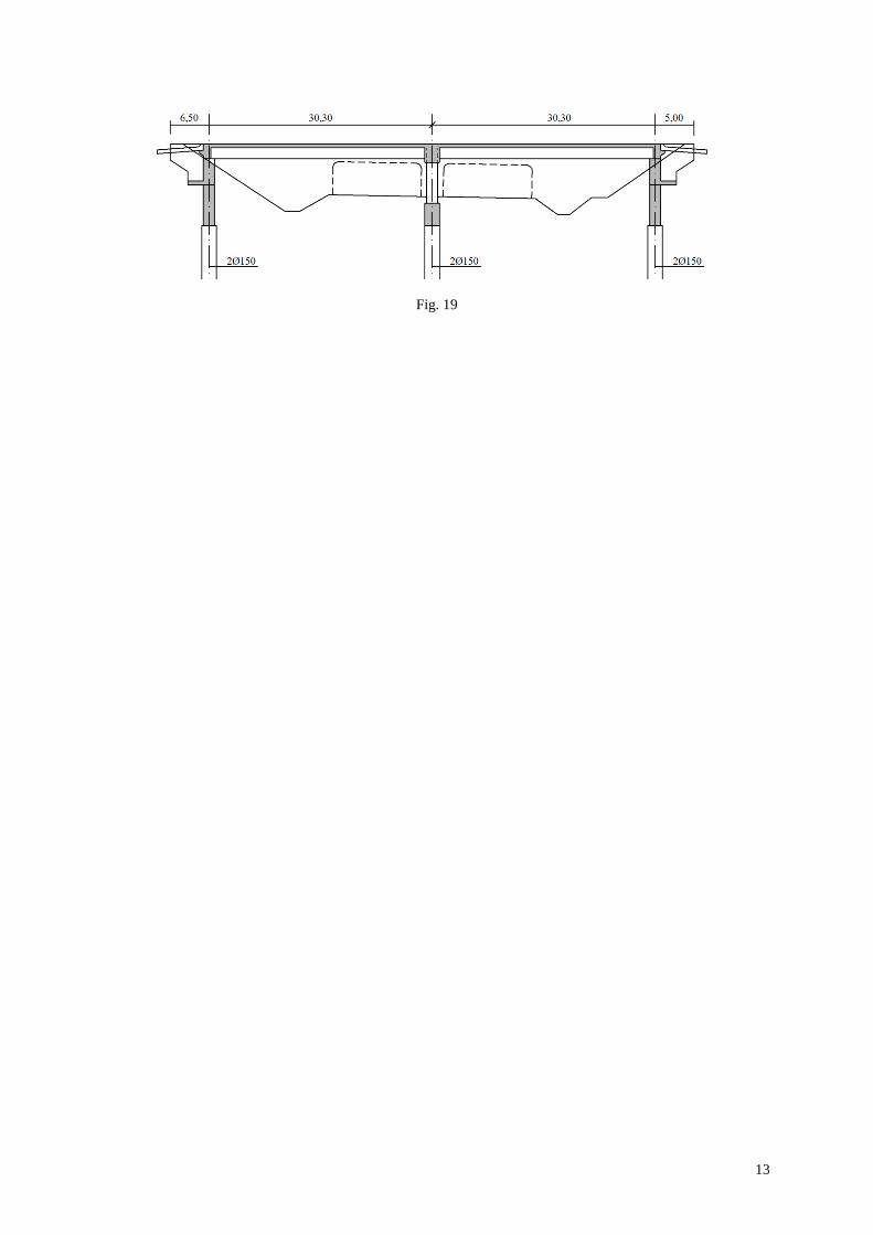
Integral bridges can also be constructed from precast T-girders of a wide and thin upper flange, and of
a web of constant width of 40 cm or more. The girders are prestressed with bonded prestressed
tendons, or with post-tensioned tendons. Above the prefabricated girders a slab of minimum thickness
of 20 cm is cast. Such a slab is composite with prefabricated girders by means of dowels. By
foreseeing cross girders above the abutments and piers, which are cast simultaneously with the slab
above the girders, a stiff connection and an integral structure is achieved.
13
Fig. 19
14
Fig. 20: Recommended cross sections of superstructures of concrete integral bridges
Tip presjeka=cross section type; skica poprečnog presjeka= cross section sketch; konstruktivna
visina=construction depth; puna ploča bez konzola=solid slab without cantilevers; pločasti nosač=slab girder;
15
trapezni pločasti nosač=trapezoidal slab girder; rebrasta ploča=double-webbed T-beam; montaţni T nosači
spregnuti sa monolitnom AB pločom = prefabricated T-girders composite with monolithic reinforced concrete
slab
As curved integral bridges react more favourably to the effects of temperature and concrete shrinkage
in comparison with straight bridges, they can be executed in greater lengths. Bridges curved in plan
have a horizontal deformation, so that they are less affected by the secondary forces due to the
temperature change and concrete creep and shrinkage. The change of the length of curved bridges
occurs on the entire bridge length, except at the abutments. Structures made of high-performance
concrete are less sensitive to forces resulting from the concrete creep and shrinkage, so integral
structures of greater lengths can be designed. The transition from the bridge to the road body requires
special solutions for longer integral bridges. Such solutions will be discussed in the following chapter.
For the Sunniberg Bridge in Switzerland, Prof. Menn has designed a curved integral structure of
526 m length, with high and elastic piers, which is a record length of integral bridges so far.
According to the British Highway Agency Standards, bridges of a length up to 60 m shall be designed
as integral bridges without any bearing and expansion joints.
In Slovenia, technical specifications for integral bridges are under preparation.
For bridges measuring 40 - 90 m in length, flexible abutments shall be designed, which can be
achieved by uniting the bored pile foundations and the abutment with shorter cantilever wing walls, as
well by adequate execution of the fill (modified backfills). In the next chapter, the design of elastic
abutments and interventions to allow deformations of integral structures will be discussed.
An omission of monolithic connection between the abutments and superstructure is only justified,
where secondary forces and moments due to the mobilized earth pressure and a very stiff foundation
are hardly mastered and controlled. Where only piers are monolithically connected with the
superstructure, a quasi-integral bridge is in question (Fig. 6d).
6. CONSTRUCTIVE SOLUTIONS OF INTEGRAL BRIDGES
Road culverts, underpasses, and minor bridges measuring up to 15 m in length, are designed as
reinforced concrete frame integral structures. Culverts and underpasses of openings up to 5 (8) m are
closed frames, while for openings (lengths) above 5 (8) m they are designed as open frames. For the
transition from the bridge structure to the road body no additional measures are required. The
completed structure is backfilled with stony material, which shall be compacted to Proctor degree of
95-98%. Fills (backfills) behind the walls shall be executed in layers, symmetrically on both sides, in
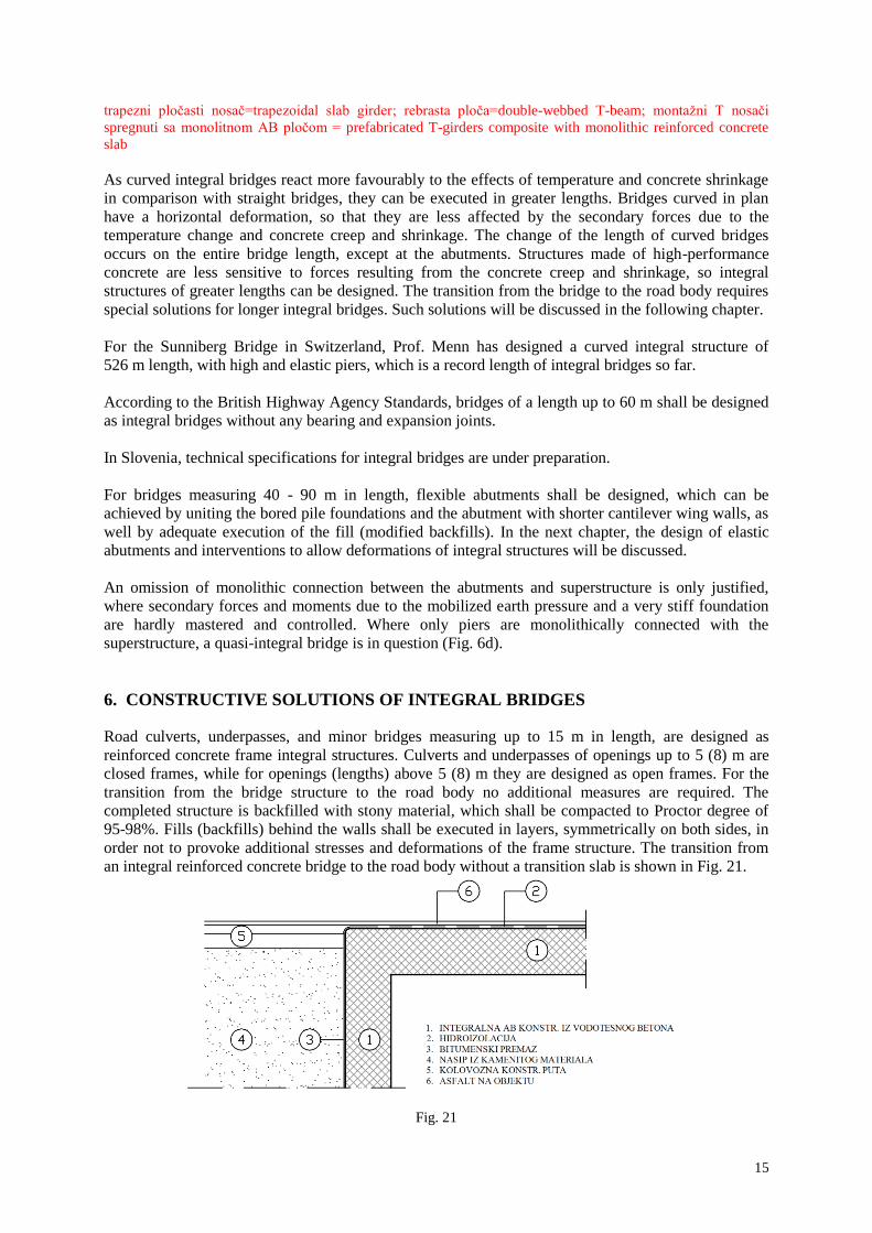
order not to provoke additional stresses and deformations of the frame structure. The transition from
an integral reinforced concrete bridge to the road body without a transition slab is shown in Fig. 21.
Fig. 21
16
1=integral RC structure made of waterproof concrete; 2=waterproofing; 3=bituminous coating; 4=fill of stony
material; 5=road pavement; 6=asphalt
Culverts and underpasses of an opening up to 8 m should preferably be lowered into the fill, so that the
road pavement can run over these structures continuously.
On motorways, however, transition slabs are required for such structures. The function of the
transition slabs is neutralise possible settlements at the structure. Deformations of structures not
exceeding 15 m in length do not cause cracks in the asphalt course.
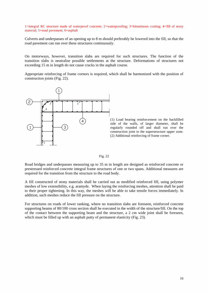
Appropriate reinforcing of frame corners is required, which shall be harmonized with the position of
construction joints (Fig. 22).
(1) Load bearing reinforcement on the backfilled
side of the walls, of larger diameter, shall be
regularly rounded off and shall run over the
construction joint to the superstructure upper zone.
(2) Additional reinforcing of frame corner.
Fig. 22
Road bridges and underpasses measuring up to 35 m in length are designed as reinforced concrete or
prestressed reinforced concrete integral frame structures of one or two spans. Additional measures are
required for the transition from the structure to the road body.
A fill constructed of stony materials shall be carried out as modified reinforced fill, using polymer
meshes of low extensibility, e.g. aramyde. When laying the reinforcing meshes, attention shall be paid
to their proper tightening. In this way, the meshes will be able to take tensile forces immediately. In
addition, such meshes reduce the fill pressure on the structure.
For structures on roads of lower ranking, where no transition slabs are foreseen, reinforced concrete
supporting beams of 80/100 cross section shall be executed in the width of the structure/fill. On the top
of the contact between the supporting beam and the structure, a 2 cm wide joint shall be foreseen,
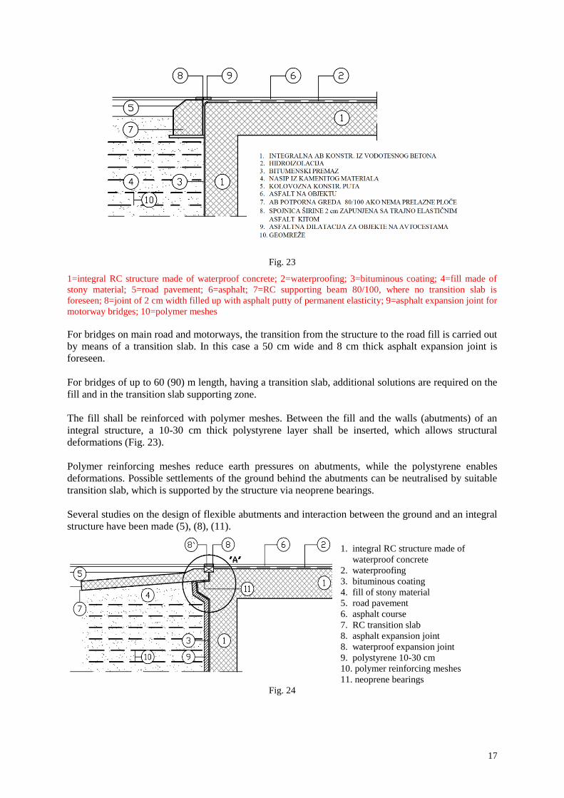
which must be filled up with an asphalt putty of permanent elasticity (Fig. 23).
17
Fig. 23
1=integral RC structure made of waterproof concrete; 2=waterproofing; 3=bituminous coating; 4=fill made of
stony material; 5=road pavement; 6=asphalt; 7=RC supporting beam 80/100, where no transition slab is
foreseen; 8=joint of 2 cm width filled up with asphalt putty of permanent elasticity; 9=asphalt expansion joint for
motorway bridges; 10=polymer meshes
For bridges on main road and motorways, the transition from the structure to the road fill is carried out
by means of a transition slab. In this case a 50 cm wide and 8 cm thick asphalt expansion joint is
foreseen.
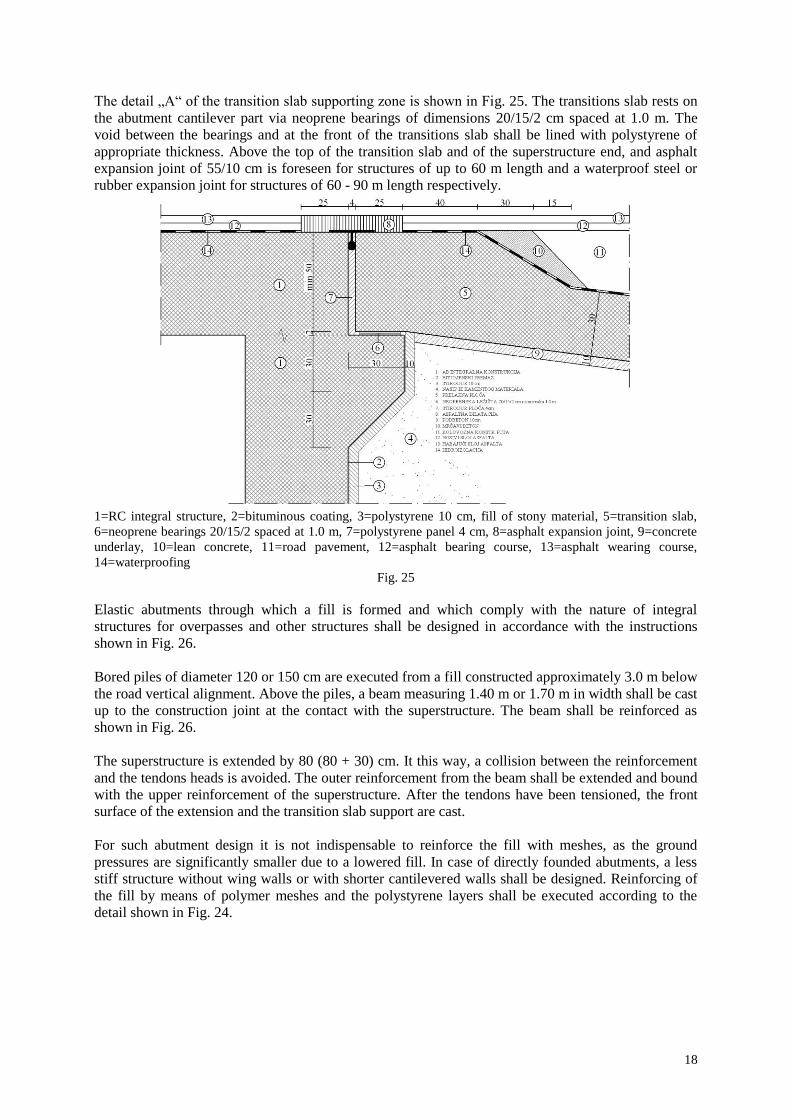
For bridges of up to 60 (90) m length, having a transition slab, additional solutions are required on the
fill and in the transition slab supporting zone.
The fill shall be reinforced with polymer meshes. Between the fill and the walls (abutments) of an
integral structure, a 10-30 cm thick polystyrene layer shall be inserted, which allows structural
deformations (Fig. 23).
Polymer reinforcing meshes reduce earth pressures on abutments, while the polystyrene enables
deformations. Possible settlements of the ground behind the abutments can be neutralised by suitable
transition slab, which is supported by the structure via neoprene bearings.
Several studies on the design of flexible abutments and interaction between the ground and an integral
structure have been made (5), (8), (11).
1. integral RC structure made of
waterproof concrete
2. waterproofing
3. bituminous coating
4. fill of stony material
5. road pavement
6. asphalt course
7. RC transition slab
8. asphalt expansion joint
8. waterproof expansion joint
9. polystyrene 10-30 cm
10. polymer reinforcing meshes
11. neoprene bearings
Fig. 24
18
The detail „A“ of the transition slab supporting zone is shown in Fig. 25. The transitions slab rests on
the abutment cantilever part via neoprene bearings of dimensions 20/15/2 cm spaced at 1.0 m. The
void between the bearings and at the front of the transitions slab shall be lined with polystyrene of
appropriate thickness. Above the top of the transition slab and of the superstructure end, and asphalt
expansion joint of 55/10 cm is foreseen for structures of up to 60 m length and a waterproof steel or
rubber expansion joint for structures of 60 - 90 m length respectively.
1=RC integral structure, 2=bituminous coating, 3=polystyrene 10 cm, fill of stony material, 5=transition slab,
6=neoprene bearings 20/15/2 spaced at 1.0 m, 7=polystyrene panel 4 cm, 8=asphalt expansion joint, 9=concrete
underlay, 10=lean concrete, 11=road pavement, 12=asphalt bearing course, 13=asphalt wearing course,
14=waterproofing
Fig. 25
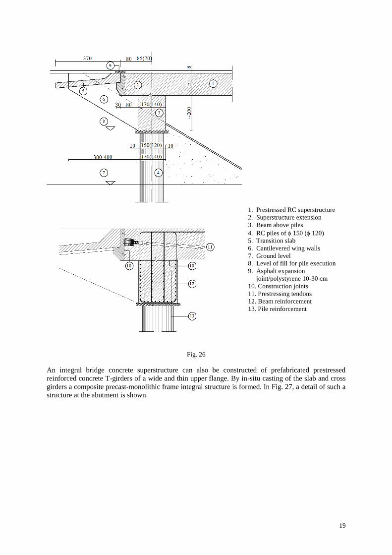
Elastic abutments through which a fill is formed and which comply with the nature of integral
structures for overpasses and other structures shall be designed in accordance with the instructions
shown in Fig. 26.
Bored piles of diameter 120 or 150 cm are executed from a fill constructed approximately 3.0 m below
the road vertical alignment. Above the piles, a beam measuring 1.40 m or 1.70 m in width shall be cast
up to the construction joint at the contact with the superstructure. The beam shall be reinforced as
shown in Fig. 26.
The superstructure is extended by 80 (80 + 30) cm. It this way, a collision between the reinforcement
and the tendons heads is avoided. The outer reinforcement from the beam shall be extended and bound
with the upper reinforcement of the superstructure. After the tendons have been tensioned, the front
surface of the extension and the transition slab support are cast.
For such abutment design it is not indispensable to reinforce the fill with meshes, as the ground
pressures are significantly smaller due to a lowered fill. In case of directly founded abutments, a less
stiff structure without wing walls or with shorter cantilevered walls shall be designed. Reinforcing of
the fill by means of polymer meshes and the polystyrene layers shall be executed according to the
detail shown in Fig. 24.
19
1. Prestressed RC superstructure
2. Superstructure extension
3. Beam above piles
4. RC piles of 150 ( 120)
5. Transition slab
6. Cantilevered wing walls
7. Ground level
8. Level of fill for pile execution
9. Asphalt expansion
joint/polystyrene 10-30 cm
10. Construction joints
11. Prestressing tendons
12. Beam reinforcement
13. Pile reinforcement
Fig. 26
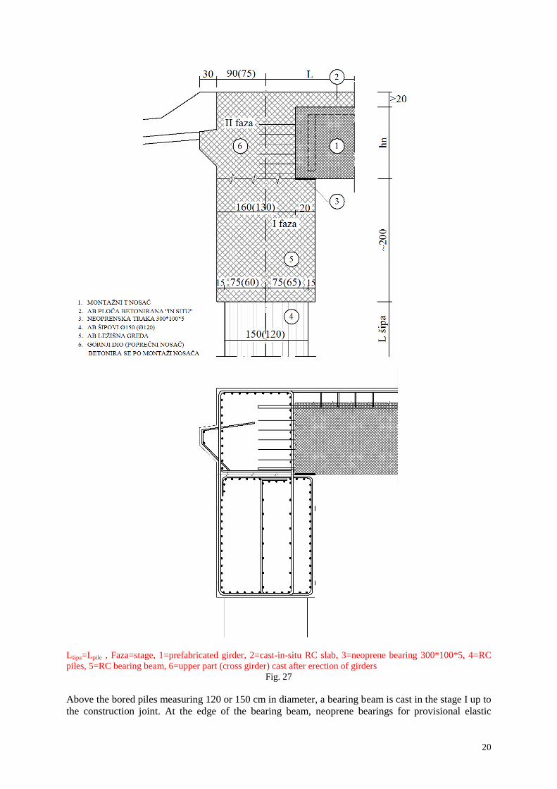
An integral bridge concrete superstructure can also be constructed of prefabricated prestressed
reinforced concrete T-girders of a wide and thin upper flange. By in-situ casting of the slab and cross
girders a composite precast-monolithic frame integral structure is formed. In Fig. 27, a detail of such a
structure at the abutment is shown.
20
Lšipa=Lpile , Faza=stage, 1=prefabricated girder, 2=cast-in-situ RC slab, 3=neoprene bearing 300*100*5, 4=RC
piles, 5=RC bearing beam, 6=upper part (cross girder) cast after erection of girders
Fig. 27
Above the bored piles measuring 120 or 150 cm in diameter, a bearing beam is cast in the stage I up to
the construction joint. At the edge of the bearing beam, neoprene bearings for provisional elastic
21
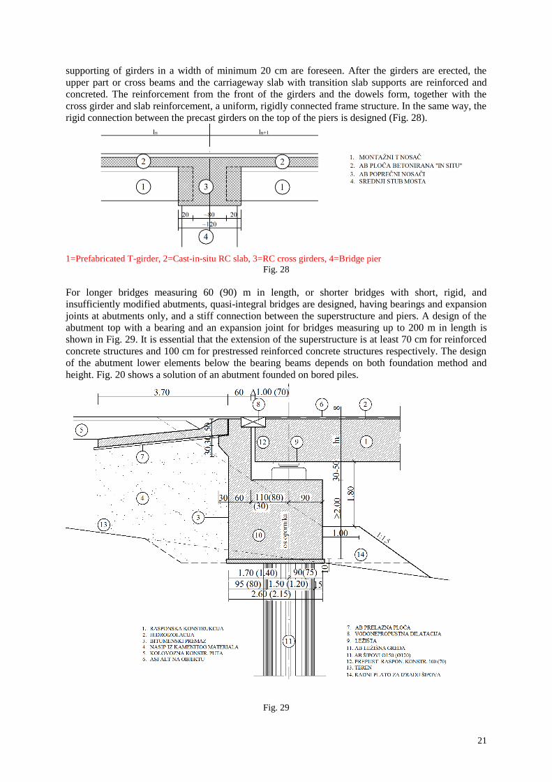
supporting of girders in a width of minimum 20 cm are foreseen. After the girders are erected, the
upper part or cross beams and the carriageway slab with transition slab supports are reinforced and
concreted. The reinforcement from the front of the girders and the dowels form, together with the
cross girder and slab reinforcement, a uniform, rigidly connected frame structure. In the same way, the
rigid connection between the precast girders on the top of the piers is designed (Fig. 28).
1=Prefabricated T-girder, 2=Cast-in-situ RC slab, 3=RC cross girders, 4=Bridge pier
Fig. 28
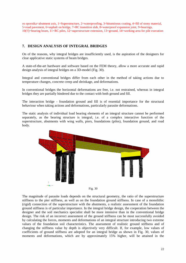
For longer bridges measuring 60 (90) m in length, or shorter bridges with short, rigid, and
insufficiently modified abutments, quasi-integral bridges are designed, having bearings and expansion
joints at abutments only, and a stiff connection between the superstructure and piers. A design of the
abutment top with a bearing and an expansion joint for bridges measuring up to 200 m in length is
shown in Fig. 29. It is essential that the extension of the superstructure is at least 70 cm for reinforced
concrete structures and 100 cm for prestressed reinforced concrete structures respectively. The design
of the abutment lower elements below the bearing beams depends on both foundation method and
height. Fig. 20 shows a solution of an abutment founded on bored piles.
Fig. 29
22
os opornika=abutment axis, 1=Superstructure, 2=waterproofing, 3=bituminous coating, 4=fill of stony material,
5=road pavement, 6=asphalt on bridge, 7=RC transition slab, 8=waterproof expansion joint, 9=bearings,
10(!!)=bearing beam, 11=RC piles, 12=superstructure extension, 13=ground, 14=working area for pile execution
7. DESIGN ANALYSIS OF INTEGRAL BRIDGES
On of the reasons, why integral bridges are insufficiently used, is the aspiration of the designers for
clear applicative static systems of beam bridges.
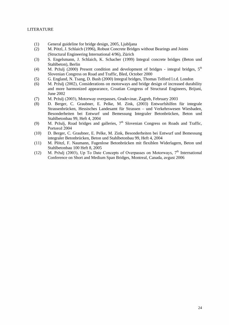
A state-of-the-art hardware and software based on the FEM theory, allow a more accurate and rapid
design analysis of integral bridges on a 3D-model (Fig. 30).
Integral and conventional bridges differ from each other in the method of taking actions due to
temperature changes, concrete creep and shrinkage, and deformations.
In conventional bridges the horizontal deformations are free, i.e. not restrained, whereas in integral
bridges they are partially hindered due to the contact with both ground and fill.
The interaction bridge - foundation ground and fill is of essential importance for the structural
behaviour when taking actions and deformations, particularly parasite deformations.
The static analysis of individual load bearing elements of an integral structure cannot be performed
separately, as the bearing structure is integral, i.e. of a complex interactive function of the
superstructure, abutments with wing walls, piers, foundations (piles), foundation ground, and road
body.
Fig. 30
The magnitude of parasite loads depends on the structural geometry, the ratio of the superstructure
stiffness to the pier stiffness, as well as on the foundation ground stiffness. In case of a monolithic
(rigid) connection of the superstructure with the abutments, a realistic assessment of the foundation
ground stiffness is of particular importance. In the integral bridge design, the cooperation between the
designer and the soil mechanics specialist shall be more intensive than in the conventional bridge
design. The risk of an incorrect assessment of the ground stiffness can be most successfully avoided
by calculating the forces, moments and deformations of an integral structure introducing two extreme
values of the foundation soil characteristics. The assessment of realistic ground stiffness and of
changing the stiffness value by depth is objectively very difficult. If, for example, low values of
coefficients of ground stiffness are adopted for an integral bridge as shown in Fig. 30, values of
moments and deformations, which are by approximately 15% higher, will be attained in the

23
superstructure middle. For higher values of coefficients of ground stiffness, values of moments, which
are by approximately 10 to 15% higher, will be calculated at the connection between the deck and the
piers. By foreseeing a small amount of extra reinforcement or tendons, extreme actions shall be taken
for both cases.
Forces and moments due to parasite actions also depend on the coefficient of expansion due to
temperature change, and on the module of elasticity of concrete. Such material characteristics can be
affected by selecting suitable aggregate.
If the static analysis shows that the parasite actions, particularly those resulting from temperature
changes, cannot be taken by a monolithic rigid connection and by a modified fill, a rigid connection
shall be omitted and a quasi-integral structure designed.
24
LITERATURE
(1) General guideline for bridge design, 2005, Ljubljana
(2) M. Pötzl, J. Schlaich (1996), Robust Concrete Bridges without Bearings and Joints
(Structural Engineering International 4/96), Zürich
(3) S. Engelsmann, J. Schlaich, K. Schacher (1999) Integral concrete bridges (Beton und
Stahlbeton), Berlin
(4) M. Prţulj (2000) Present condition and development of bridges - integral bridges, 5th
Slovenian Congress on Road and Traffic, Bled, October 2000
(5) G. England, N. Tsang, D. Bush (2000) Integral bridges, Thomas Telford l.t.d. London
(6) M. Prţulj (2002), Considerations on motorways and bridge design of increased durability
and more harmonized appearance, Croatian Congress of Structural Engineers, Brijuni,
June 2002
(7) M. Prţulj (2003), Motorway overpasses, GraĎevinar, Zagreb, February 2003
(8) D. Berger, C. Graubner, E. Pelke, M. Zink, (2003) Entwurfshilfen für integrale
Strassenbrücken, Hessisches Landesamt für Strassen – und Verkehrswesen Wiesbaden,
Besonderheiten bei Entwurf und Bemessung Integraler Betonbrücken, Beton und
Stahlbetonbau 99, Heft 4, 2004
(9) M. Prţulj, Road bridges and galleries, 7th Slovenian Congress on Roads and Traffic,
Portoroţ 2004
(10) D. Berger, C. Graubner, E. Pelke, M. Zink, Besonderheiten bei Entwurf und Bemessung
integraler Betonbrücken, Beton und Stahlbetonbau 99, Heft 4, 2004
(11) M. Plötzl, F. Naumann, Fugenlose Betonbrücken mit flexiblen Widerlagern, Beton und
Stahlbetonbau 100 Heft 8, 2005
(12) M. Prţulj (2003), Up To Date Concepts of Overpasses on Motorways, 7th International
Conference on Short and Medium Span Bridges, Montreal, Canada, avgust 2006
Recommended