Installation Manual
Trailer EditionSB-110, SB-200TG, SB-210 and SB-310 Single Temperature SystemsTK 52768-2-IM (Rev. 5, 01/10)
Copyright© 2004 Thermo King Corp., Minneapolis, MN,
U.S.A.Printed in U.S.A.
2
Release History
Released (10/04)
Rev. 1 (11/04) Updated to new style bottom pan released by engineering.
Rev. 2 (04/05) Added optional remote controller and harness, new door switch information and additional battery specifications.
Rev. 3 (02/06) Page 38 - Added DOT/Federal Highway Regulations information regarding installing fuel tank under trailer.
Rev. 4 (01/07) Added SB-200TG to the manual.
Rev. 5 (01/10) Pages 60-61 - Added new heavy duty battery hold down bracket.
3
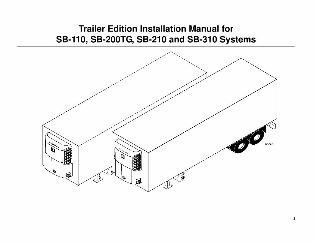
Trailer Edition Installation Manual for
SB-110, SB-200TG, SB-210 and SB-310 Systems
4
Introduction
Installation Manual-A was written to assist with the installation of the
Thermo King SB-110, SB-200TG, SB-210 and SB-310 Single
Temperature refrigeration systems onto trailers specifically designed and
built for refrigerated applications.
Due to its complexity, you should not attempt this installation unless you:
• Are an experienced mechanic
• Can safely lift 34 kilos (75 lbs.)
• Are certified or trained in the repair and maintenance of diesel powered
refrigeration systems
• Have a basic understanding of electricity and electrical wiring
• Have the necessary tools and equipment to complete the installation.
This manual is published for informational purposes only. Thermo King makes no representations warranties express or implied, with respect to
the information recommendations and descriptions contained herein. Information provided should not be regarded as all-inclusive or covering
all contingencies. If further information is required, Thermo King Corporation Service Department should be consulted.
Thermo King’s warranty shall not apply to any equipment which has been “so installed, maintained, repaired or altered as, in the
manufacturer’s judgment, to affect its integrity.”
Manufacturer shall have no liability to any person or entity for any personal injury, property damage or any other direct, indirect,
special, or consequential damages whatsoever, arising out of the use of this manual or any information, recommendations or
descriptions contained herein.
5
Table of Contents
Introduction . . . . . . . . . . . . . . . . . . . . . . . . . . . . . . . . . . . . . . . . . . . . . . . . . . . . 4
Safety Precautions . . . . . . . . . . . . . . . . . . . . . . . . . . . . . . . . . . . . . . . . . . . . . . 6
Required Tools . . . . . . . . . . . . . . . . . . . . . . . . . . . . . . . . . . . . . . . . . . . . . . . . . 8
Installation Components . . . . . . . . . . . . . . . . . . . . . . . . . . . . . . . . . . . . . . . . . 10
Trailer Requirements . . . . . . . . . . . . . . . . . . . . . . . . . . . . . . . . . . . . . . . . . . . . 12
Evaporator Opening Dimensions . . . . . . . . . . . . . . . . . . . . . . . . . . . . . . . . . . 14
Mounting Bolt Dimensions . . . . . . . . . . . . . . . . . . . . . . . . . . . . . . . . . . . . . . . 16
Unit Dimensions . . . . . . . . . . . . . . . . . . . . . . . . . . . . . . . . . . . . . . . . . . . . . . . 18
Bulkhead Dimensions . . . . . . . . . . . . . . . . . . . . . . . . . . . . . . . . . . . . . . . . . . . 20
Battery Dimensions . . . . . . . . . . . . . . . . . . . . . . . . . . . . . . . . . . . . . . . . . . . . . 22
Status Light Dimensions . . . . . . . . . . . . . . . . . . . . . . . . . . . . . . . . . . . . . . . . 24
Single Temperature Rear Remote Controller Dimensions (OPTION) . . . . . 26
Door Switch Dimensions (OPTION) . . . . . . . . . . . . . . . . . . . . . . . . . . . . . . . . 28
Lifting Bar Dimensions . . . . . . . . . . . . . . . . . . . . . . . . . . . . . . . . . . . . . . . . . . 30
Unpacking the Unit . . . . . . . . . . . . . . . . . . . . . . . . . . . . . . . . . . . . . . . . . . . . . 32
Installing the Unit . . . . . . . . . . . . . . . . . . . . . . . . . . . . . . . . . . . . . . . . . . . . . . 34
Installing the Drain Hoses . . . . . . . . . . . . . . . . . . . . . . . . . . . . . . . . . . . . . . . 36
Installing the Fuel Tank . . . . . . . . . . . . . . . . . . . . . . . . . . . . . . . . . . . . . . . . . 38
Installing the Fuel Lines . . . . . . . . . . . . . . . . . . . . . . . . . . . . . . . . . . . . . . . . . 40
Installing the Status Light Kit (OPTION) . . . . . . . . . . . . . . . . . . . . . . . . . . . . 42
Installing the Single Temperature Rear Remote Controller (OPTION) . . . . 44
Installing the Door Switch (OPTION) . . . . . . . . . . . . . . . . . . . . . . . . . . . . . . . 48
CargoWatch Sensor Locations . . . . . . . . . . . . . . . . . . . . . . . . . . . . . . . . . . . 52
Connecting the CargoWatch Sensors . . . . . . . . . . . . . . . . . . . . . . . . . . . . . 54
Connecting the DAS Sensors - SB-200TG ONLY . . . . . . . . . . . . . . . . . . . . . 56
Installing the Bulkhead . . . . . . . . . . . . . . . . . . . . . . . . . . . . . . . . . . . . . . . . . . 58
Installing the Battery . . . . . . . . . . . . . . . . . . . . . . . . . . . . . . . . . . . . . . . . . . . 60
Installing the Bottom Pan . . . . . . . . . . . . . . . . . . . . . . . . . . . . . . . . . . . . . . . . 62
SYSTEM CHECK LIST . . . . . . . . . . . . . . . . . . . . . . . . . . . . . . . . . . . . . . . . . . . 64
Troubleshooting Guide . . . . . . . . . . . . . . . . . . . . . . . . . . . . . . . . . . . . . . . . . 65
6
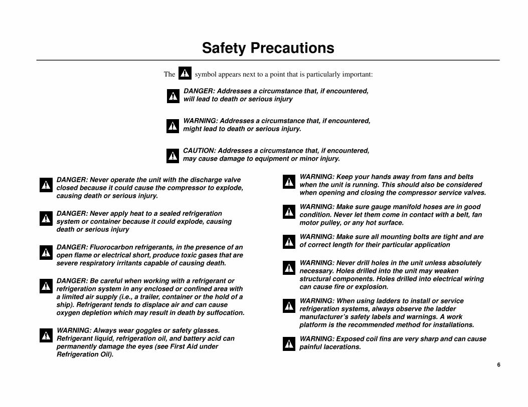
Safety Precautions
The symbol appears next to a point that is particularly important:
DANGER: Addresses a circumstance that, if encountered, will lead to death or serious injury
WARNING: Addresses a circumstance that, if encountered, might lead to death or serious injury.
CAUTION: Addresses a circumstance that, if encountered, may cause damage to equipment or minor injury.
DANGER: Never operate the unit with the discharge valve closed because it could cause the compressor to explode, causing death or serious injury.
DANGER: Never apply heat to a sealed refrigeration system or container because it could explode, causing death or serious injury
DANGER: Fluorocarbon refrigerants, in the presence of an open flame or electrical short, produce toxic gases that are severe respiratory irritants capable of causing death.
DANGER: Be careful when working with a refrigerant or refrigeration system in any enclosed or confined area with a limited air supply (i.e., a trailer, container or the hold of a ship). Refrigerant tends to displace air and can cause oxygen depletion which may result in death by suffocation.
WARNING: Always wear goggles or safety glasses. Refrigerant liquid, refrigeration oil, and battery acid can permanently damage the eyes (see First Aid under Refrigeration Oil).
WARNING: Keep your hands away from fans and belts when the unit is running. This should also be considered when opening and closing the compressor service valves.
WARNING: Make sure gauge manifold hoses are in good condition. Never let them come in contact with a belt, fan motor pulley, or any hot surface.
WARNING: Make sure all mounting bolts are tight and are of correct length for their particular application
WARNING: Never drill holes in the unit unless absolutely necessary. Holes drilled into the unit may weaken structural components. Holes drilled into electrical wiring can cause fire or explosion.
WARNING: When using ladders to install or service refrigeration systems, always observe the ladder manufacturer’s safety labels and warnings. A work platform is the recommended method for installations.
WARNING: Exposed coil fins are very sharp and can cause painful lacerations.
7
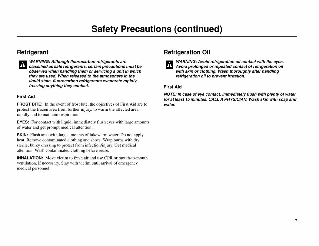
Safety Precautions (continued)
Refrigerant
First Aid
FROST BITE: In the event of frost bite, the objectives of First Aid are to
protect the frozen area from further injury, to warm the affected area
rapidly and to maintain respiration.
EYES: For contact with liquid, immediately flush eyes with large amounts
of water and get prompt medical attention.
SKIN: Flush area with large amounts of lukewarm water. Do not apply
heat. Remove contaminated clothing and shoes. Wrap burns with dry,
sterile, bulky dressing to protect from infection/injury. Get medical
attention. Wash contaminated clothing before reuse.
INHALATION: Move victim to fresh air and use CPR or mouth-to-mouth
ventilation, if necessary. Stay with victim until arrival of emergency
medical personnel.
Refrigeration Oil
First Aid
NOTE: In case of eye contact, immediately flush with plenty of water
for at least 15 minutes. CALL A PHYSICIAN. Wash skin with soap and
water.
WARNING: Although fluorocarbon refrigerants are classified as safe refrigerants, certain precautions must be observed when handling them or servicing a unit in which they are used. When released to the atmosphere in the liquid state, fluorocarbon refrigerants evaporate rapidly, freezing anything they contact.
WARNING: Avoid refrigeration oil contact with the eyes. Avoid prolonged or repeated contact of refrigeration oil with skin or clothing. Wash thoroughly after handling refrigeration oil to prevent irritation.
8
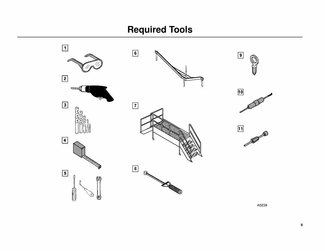
Required Tools
1. Safety Glasses
2. Drill
3. Drill Bits
4. Tape Measure
5. Mechanics Tools
6. Lifting Bar
7. Work Platform (Recommended)
8. Torque Wrench
9. Forged Eyebolts
10. Deutsch Wedge Remover (P/N 204-799)
11. Deutsch Pin Remover (P/N 204-737)
NOTE: Equipment such as scales, gauges, refrigerant leak detectors, and torque wrenches should be in good working condition and routinely
calibrated to assure accurate readings.
9
Required Tools
10
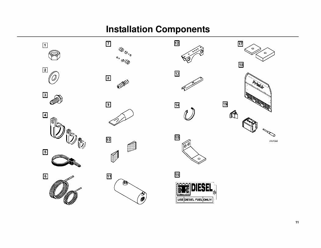
Installation Components
1. Locking Nuts
2. Washers
3. Self Tapping Screws
4. Clamps
5. Cable Ties
6. Fuel Lines Hose
1/4 in.
3/8 in.
7. Fuel Line Fittings
1/4 in.
3/8 in.
8. Fuel Line Connector
9. Drain Hose Check Valve
10. Vinyl Taper Strips
11. Fuel Tank
12. Fuel Tank Hanger
13. Fuel Tank Support Channel
14. Fuel Tank Mounting Strap
15. Fuel Tank Mounting Brackets
16. Fuel Tank Nameplate
17. Fuel Tank Backing Plate
18. Bulkhead (option)
19. Deutsch 6-Pin Connector, Wedge and Terminal Pins
11
Installation Components
12
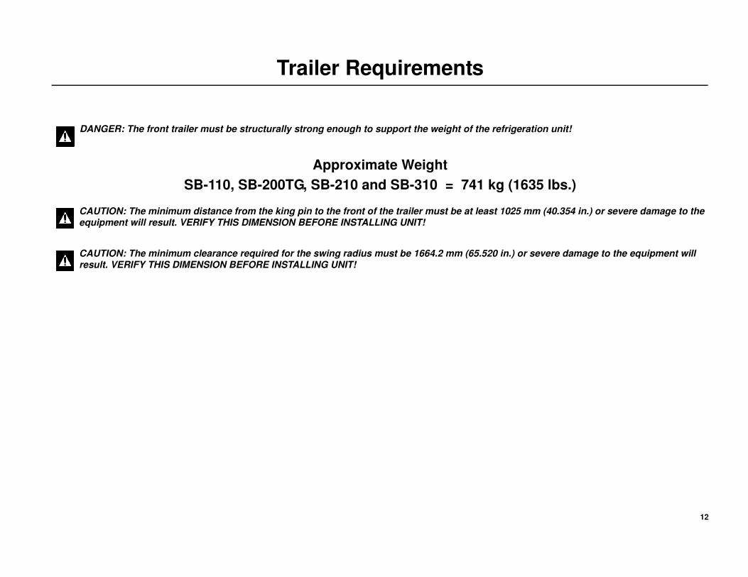
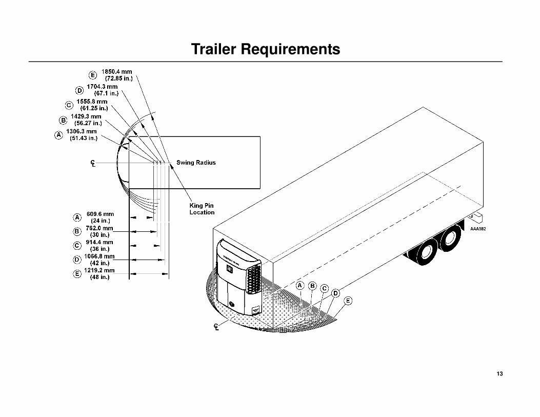
Trailer Requirements
Approximate Weight
SB-110, SB-200TG, SB-210 and SB-310 = 741 kg (1635 lbs.)
DANGER: The front trailer must be structurally strong enough to support the weight of the refrigeration unit!
CAUTION: The minimum distance from the king pin to the front of the trailer must be at least 1025 mm (40.354 in.) or severe damage to the equipment will result. VERIFY THIS DIMENSION BEFORE INSTALLING UNIT!
CAUTION: The minimum clearance required for the swing radius must be 1664.2 mm (65.520 in.) or severe damage to the equipment will result. VERIFY THIS DIMENSION BEFORE INSTALLING UNIT!
13
Trailer Requirements

14
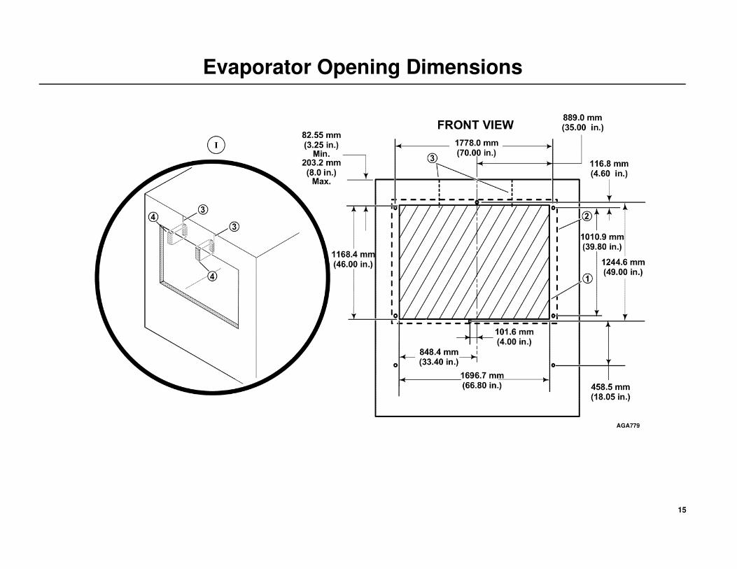
Evaporator Opening Dimensions
EVAPORATOR OPENING
The location of the unit mounting bolts and evaporator opening in the front
wall is critical. VERIFY ALL DIMENSIONS BEFORE INSTALLING
UNIT!
NOTE: It may be necessary to relocate the front corner clearance
lights to the corner radius of the trailer to prevent damage.
1. The evaporator opening must be square. The diagonal measurements
must be ±3.0 mm (0.12 in.)
2. The gasket surface around the opening must be at least 76.2 mm
(3.00 in.) wide, be flat ±3.2 mm (0.05 in.) and free of rivets, seams or
bolt heads.
3. Trailers often have overlap vertical seams above the unit opening
which cause poor gasket sealing and adversely effect the performance
of your Thermo King unit (Detail I).
4. To provide proper sealing surface at these seams, install the vinyl taper
strips supplied in the installation kit (Detail I).
Vinyl Taper Strip Installation Instructions
• Clean trailer surface area of overlap seams above opening.
• Peel off paper backing from vinyl taper strip.
• Apply vinyl taper strip to trailer seams, positioning thicker side along
edge of seam (Detail I).
DANGER: The front trailer wall must be structurally strong enough to support the weight of the refrigeration unit!
15
Evaporator Opening Dimensions
AGA779
16
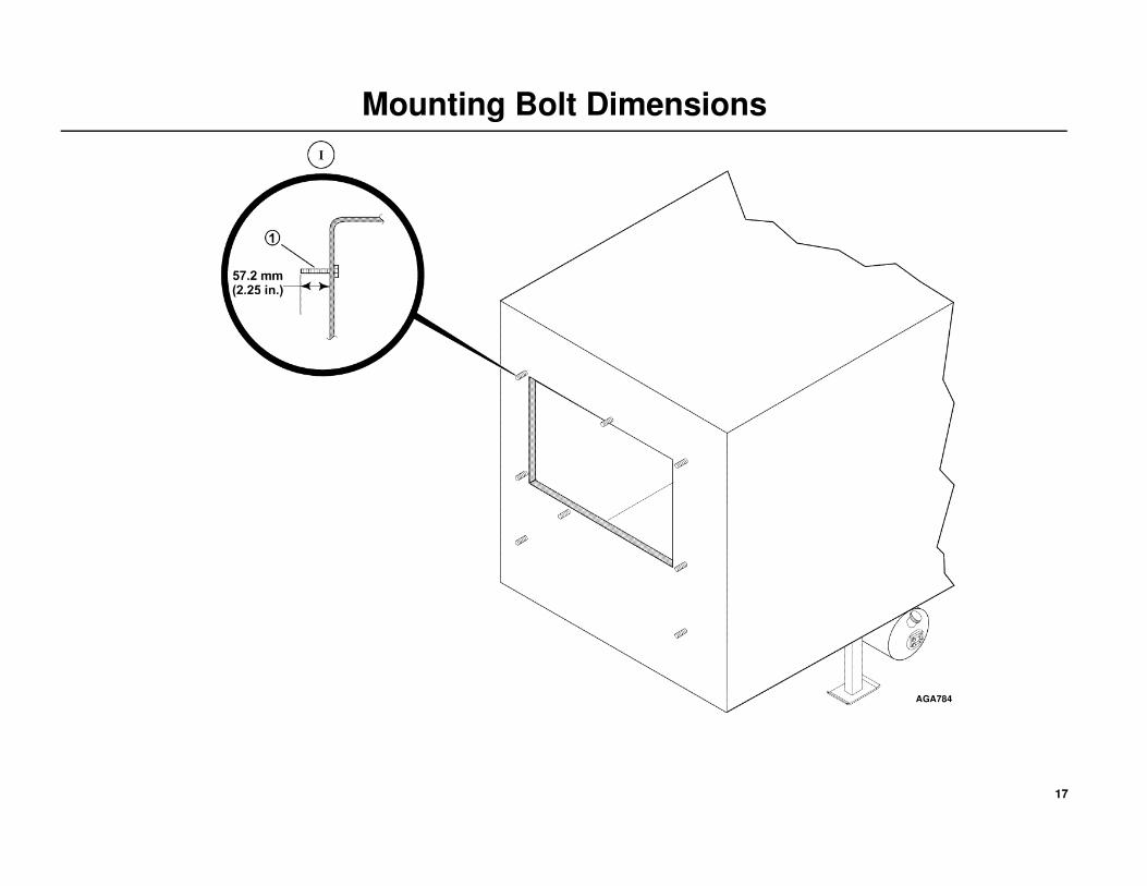
Mounting Bolt Dimensions
Mounting Bolts
NOTE: The location of the unit mounting bolts in the trailer front wall
is critical to proper unit installation.
All mounting bolts must be square with the front wall and securely
fastened to the trailer wall in such a manner to allow the mounting nuts be
torqued to 82 N•m (60 ft. lbs.) from outside the trailer.
1. Mounting bolts are to extend 57.2 mm (2.25 in.) beyond the front wall
(Detail I).
2. Surface of all mounting bolts are to be flat within 2.5 mm (0.10 in.).
Mounting Bolts Specifications
Use Metric M12 x 1.75 pitch class 8.8 (1/2 in.-13 UNC - 28 Rolled thread
grade 5), medium carbon steel bolts and locking nuts. All hardware must
be zinc plated with dichromate finish.
DANGER: Eight mounting bolts must be installed to properly secure the unit to the trailer front wall! Failure to do so could result in severe damage to equipment, void the warranty or cause personal injury or death!
DANGER: The use of mounting bolts other than those specified could result in severe damage to equipment, void the warranty or cause personal injury or death!
17
Mounting Bolt Dimensions
AGA784

18
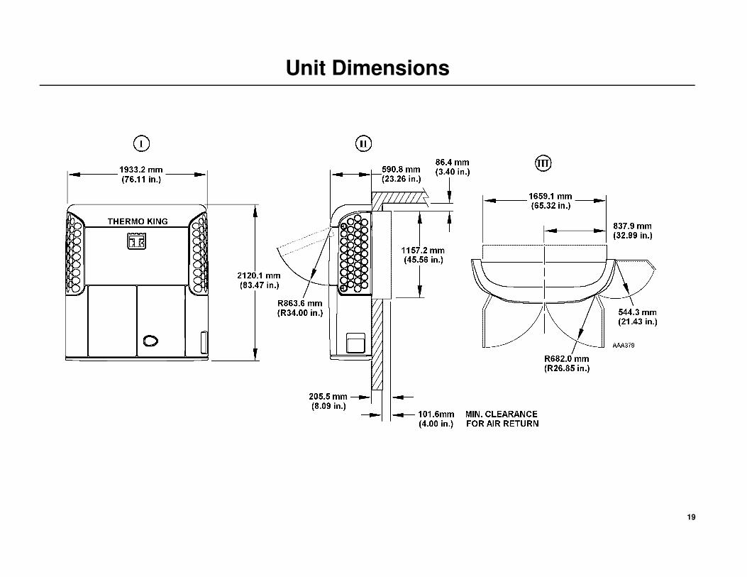
Unit Dimensions
I. Front View
II. Side View
III. Top View
19
Unit Dimensions
20
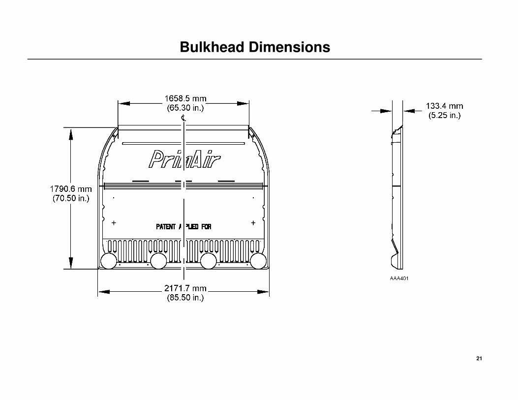
Bulkhead Dimensions
THERMO KING RECOMMENDS USING A BULKHEAD
Bulkheads are available from authorized Thermo King Dealers.
Return Airflow
Restrictions of the return airflow adversely affects the performance of the
unit. The area directly behind the evaporator return air inlet must not be
restricted.
Bulkhead Function
A bulkhead is used to keep the return airflow from being restricted if the
load shifts. The bulkhead also prevents the load from shifting into the
return airflow passageway on the front wall of the trailer.
Typical Bulkhead Shown (Dimensions are approximate)
I. Front View
II. Side View
21
Bulkhead Dimensions
22
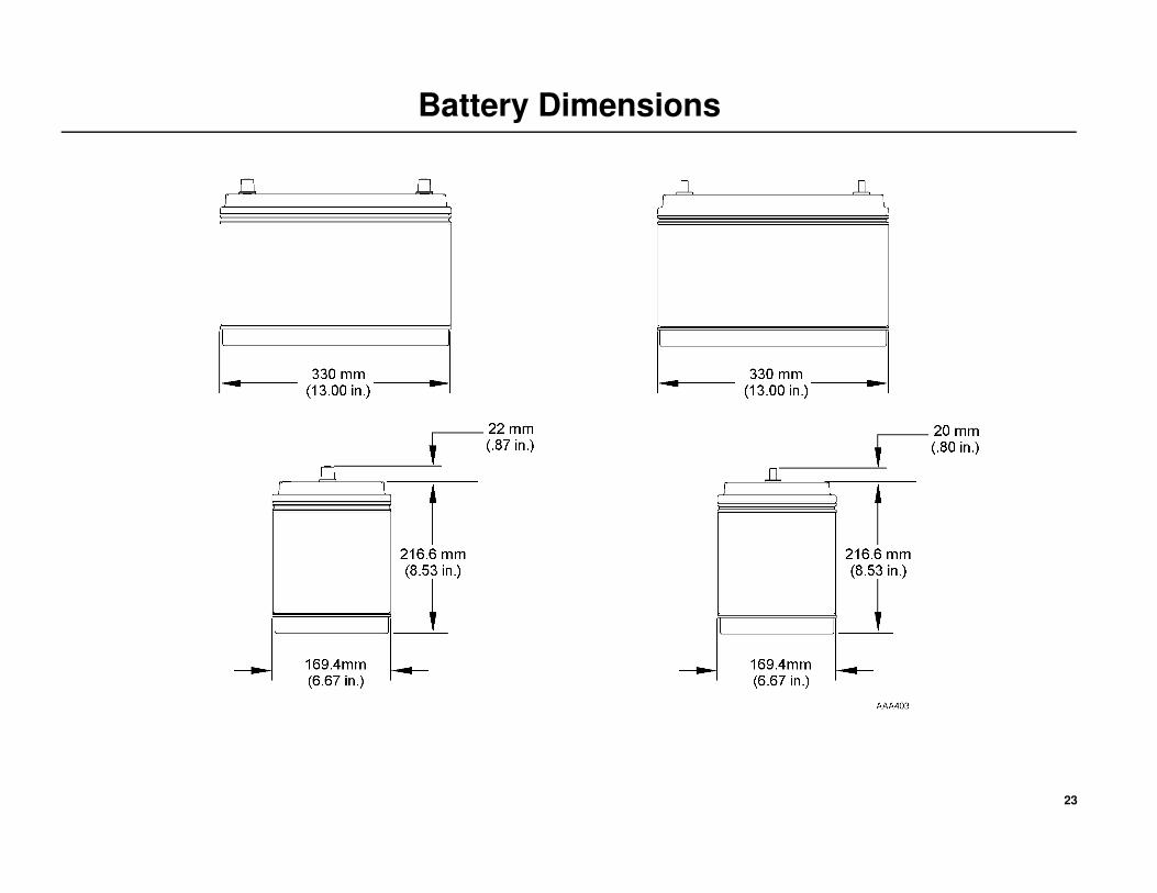
Battery Dimensions
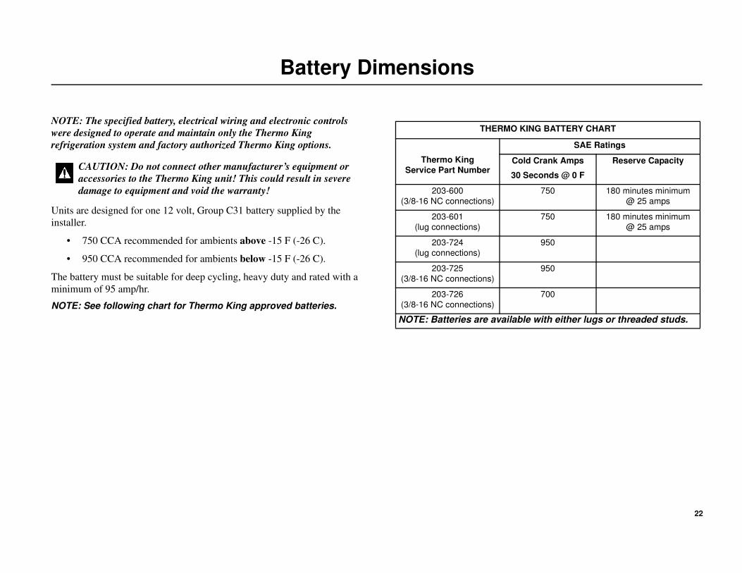
NOTE: The specified battery, electrical wiring and electronic controls
were designed to operate and maintain only the Thermo King
refrigeration system and factory authorized Thermo King options.
Units are designed for one 12 volt, Group C31 battery supplied by the
installer.
• 750 CCA recommended for ambients above -15 F (-26 C).
• 950 CCA recommended for ambients below -15 F (-26 C).
The battery must be suitable for deep cycling, heavy duty and rated with a
minimum of 95 amp/hr.
NOTE: See following chart for Thermo King approved batteries.
CAUTION: Do not connect other manufacturer’s equipment or
accessories to the Thermo King unit! This could result in severe
damage to equipment and void the warranty!
THERMO KING BATTERY CHART
Thermo King
Service Part Number
SAE Ratings
Cold Crank Amps
30 Seconds @ 0 F
Reserve Capacity
203-600
(3/8-16 NC connections)
750 180 minutes minimum
@ 25 amps
203-601
(lug connections)
750 180 minutes minimum
@ 25 amps
203-724
(lug connections)
950
203-725
(3/8-16 NC connections)
950
203-726
(3/8-16 NC connections)
700
NOTE: Batteries are available with either lugs or threaded studs.
23
Battery Dimensions

24
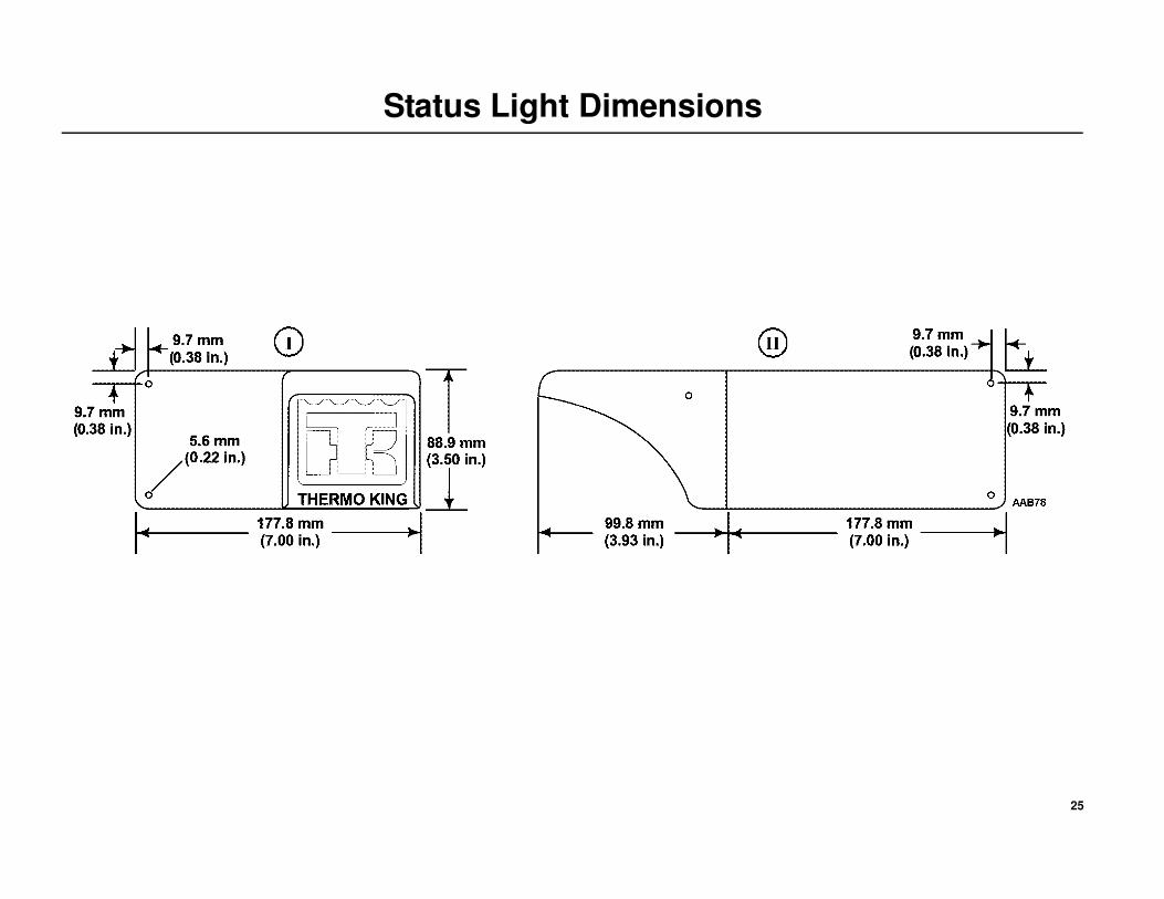
Status Light Dimensions
I. Front View
II. Side View
25
Status Light Dimensions
26
Single Temperature Rear Remote Controller Dimensions
(OPTION)
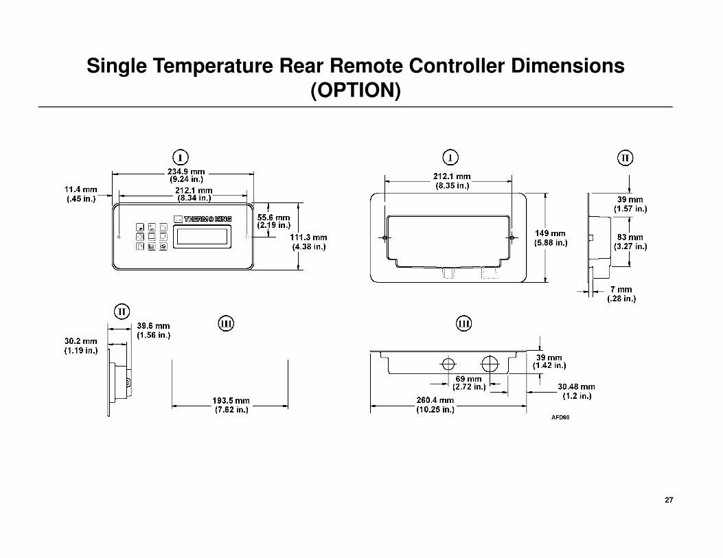
I. Front View
II. End View
III. Side View
27
Single Temperature Rear Remote Controller Dimensions
(OPTION)
28
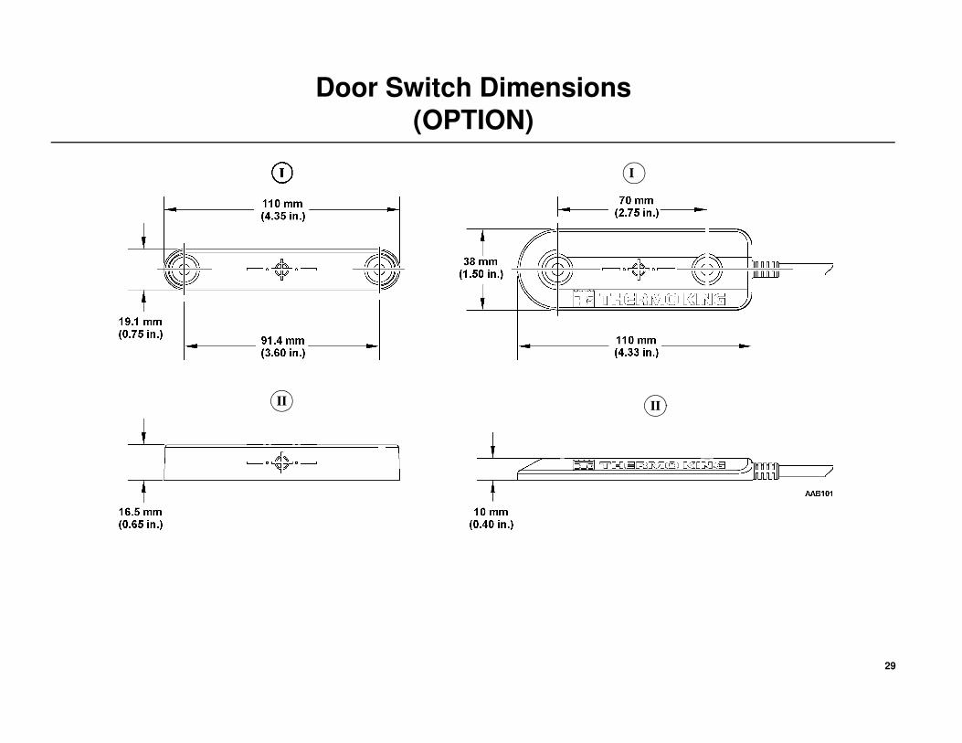
Door Switch Dimensions
(OPTION)
I. Front View
II. Side View
29
Door Switch Dimensions
(OPTION)
II II
I
30
Lifting Bar Dimensions
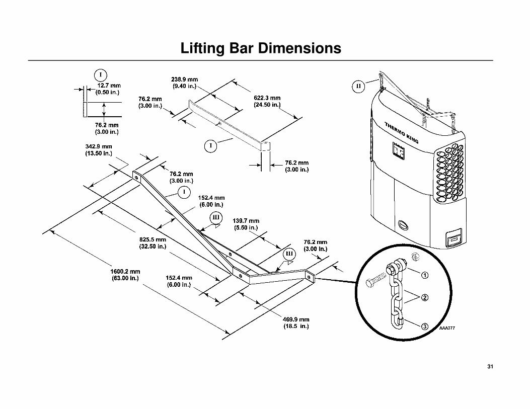
I. Recommended material: 76.2 mm (3.00 in.) x 12.7 mm (0.50 in.) mild
steel.
II. Use forged chain links and hooks, clevis and pins with strength equal to
total lift capacity of hoist mechanism and meet all safety standards.
III. Bolt together for maximum strength and safety.
1. Forged Clevis Pin.
2. Forged Chain Links.
3. Locking Master Chain Link.
WARNING: Do not use a fork lift to install unit!
WARNING: Thermo King requires a 3 point lifting bar to safely lift and install units. A lifting bar can be made from the drawings provided.
WARNING: All hardware used to assemble the lifting bar must be DIN 931 class 10.9 (SAE grade 8). The use of hardware other than specified may cause personal injury, severe damage to the evaporator and void the warranty.
WARNING: The lifting bar and lifting device combined must be able to support minimum weight of 1360.8 kilos (1 1/2 tons).
31
Lifting Bar Dimensions
32
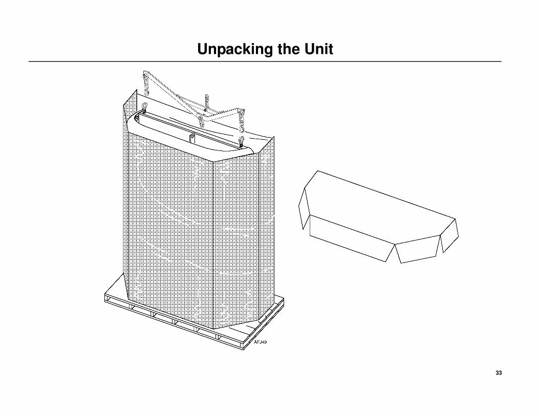
Unpacking the Unit
Units are shipped attached to disposable wooden pallet and wrapped with
protective cardboard and plastic stretch wrap.
NOTE: To avoid unnecessary damage to your unit, place the crated
unit near the trailer prior to its removal.
IMPORTANT: DO NOT use a sharp knife to remove the stretch wrap or
cardboard wrap as damage to the exterior of the unit will result!
Unpacking the Unit
• Carefully remove plastic stretch wrap from unit.
• Carefully remove the top cardboard cover.
• Carefully remove the outer cardboard wrap.
• Remove installation kit boxes, bottom panel, and any other loose
components from rear of unit.
• Attach forged eyebolts and 3 point lifting bar to unit.
• Remove hardware holding unit to wooden pallet.
• Unit is now ready for installation.
DANGER: Do not use a forklift to install the unit! This could result in severe damage to the equipment, void the warranty or cause personal injury or death!
WARNING: Thermo King requires a 3 point lifting bar to safely
lift and install units. A lifting bar can be made from the drawings
provided (see Lifting Bar Dimensions).
33
Unpacking the Unit
34
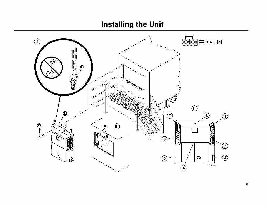
Installing the Unit
Access to Mounting Holes (Detail II).
1. Top side mounting hole through the hinged roadside grille.
2. Center side mounting hole through hinged roadside grille.
3. Lower side mounting hole through hinged roadside panel, and control
box hole.
4. Center side mounting hole through hinged lower curbside door.
5. Lower side mounting hole through hinged curbside panel.
6. Center side mounting hole through hinged curbside grille.
7. Top side mounting hole through hinged curbside grille.
8. Top center mounting hole from top of the unit.
Unit Installation
9. Trailers often have overlap seams above the unit opening which cause
poor gasket sealing and adversely effect the performance of your
Thermo King unit (Detail III).
10. To provide proper sealing surface at these seams, install the vinyl taper
strips supplied in the installation kit (Detail III).
Vinyl Taper Strip Installation Instructions
• Clean trailer surface area of overlap seams above opening.
• Peel off paper backing from vinyl taper strip.
Apply vinyl taper strip to trailer seams positioning thicker side along edge
of seam.
11. Install two 5/8-11 forged lifting eyebolts into threaded holes located on
the top of the unit (Detail I).
12. Use the lifting bar to lift unit up to the trailer opening.
NOTE: All nuts that hold the unit to the trailer should be elastic stop
nuts (Nylock Type) provided in the installation kit.
13. Attach washer and elastic stop nuts provided in the installation kit.
Torque to 82 N•m (60 ft. lbs.).
WARNING: Do not use a forklift to install the unit! This could result in severe damage to equipment, void the warranty or cause personal injury or death!
WARNING: Use only locking hooks to safely lift the unit! Failure to use locking hooks could result in severe damage to the equipment, void the warranty or cause personal injury or death! (Detail I).
WARNING: Thermo King requires a 3 point lifting bar to safely lift and install units. A lifting bar can be made from the drawings provided (see Lifting Bar Dimensions).
35
Installing the Unit

36
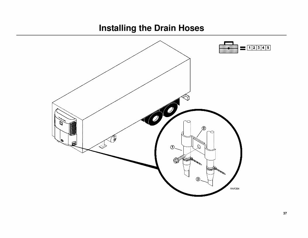
Installing the Drain Hoses
1. Drain Hoses should run straight down the trailer wall from the unit with
no kinks or bends.
2. Secure with screws and clamps provided in installation kit.
3. Cut off excess hose and attach drain hose check valves provided in
installation kit.
37
Installing the Drain Hoses
38
Installing the Fuel Tank
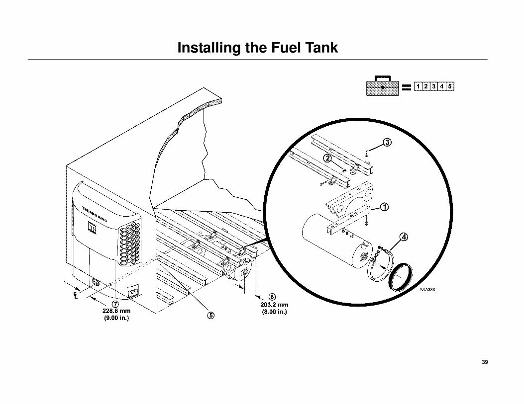
NOTE: Thermo King supplies the Fuel Tank, Fuel Tank Hangers, Fuel
Tank Channels and Fuel Tank Straps. Due to differences in trailer
manufacturers, additional support channels may be required to
safely support the overall weight of the fuel tank components
including the full capacity of diesel fuel. Consult your trailer
manufacturer for specific details on proper fuel tank installation and
recommendations.
Installation Recommendations
1. Fuel Tank Channel must be used with every tank installation.
NOTE: This drawing shows a typical installation with 304.8 mm
(12.00 in.) crossmember spacing. For other crossmember
spacing, refer to TK drawing 5937C22.
2. Torque 1/2 in. hardware to 81 - 88 N•m (60 - 65 ft/lb).
3. Torque 3/8 in. hardware to 48 N•m (35 ft/lb).
4. Torque band clamping hardware to 48 N•m (35 ft/lb).
5. Route fuel lines from fuel tank, through conduit and connect to unit.
Clamp every 609.6 mm (24.0 in.).
6. Thermo King recommends the fuel tank be mounted 203.2 mm
(8.00 in.) inside of the trailer frame. Otherwise, the OEM or installer is
responsible to ensure the fuel tank position meets or exceeds DOT or
Federal Highway regulations, when applicable.
7. Position fuel line 228.6 mm (9.00 in.) from center line of trailer.
DANGER: An improperly installed fuel tank could lead to serious injury or death! Consult your trailer manufacturer for specific details on proper fuel tank installation and recommendations.
39
Installing the Fuel Tank
40
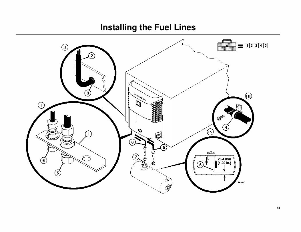
Installing the Fuel Lines
1. Install the fuel line bracket to the pre-drilled hole in the frame. This
hole is located in the frame under the compressor (Detail I).
2. Fuel lines should be routed in a protective housing with no kinks or
sharp bends (Detail II).
3. Rubber grommets must be used when routing fuel lines through holes
in metal (Detail III).
4. Secure all fuel lines with provided clamps (Detail III).
5. Route fuel supply line from the unit to the fuel pump to the fuel pickup
on the fuel tank. Install fuel line connector (provided in installation kit),
cut end of fuel line at a 45 degree angle and insert into fuel pickup tube
until it is 25.4 mm (1.00 in.) from bottom of tank and tighten securely
(Detail IV).
6. Route fuel return line from the unit to the fuel tank return fitting.
Attach fuel line connectors and tighten securely.
7. Remove plastic cap from the fuel vent and point the outlet to the rear of
the trailer.
NOTE: Add a sufficient amount of fuel (1/4 tank) to allow the unit to
run for 8 to 12 hours during engine break-in and pre-delivery
procedures.
DANGER: Leaking fuel lines could cause a fire resulting in death or serious injury! All fuel line fittings must be tight and leak free!
DANGER: Do not route fuel lines with battery cables or electrical wires, as this could cause a fire!
41
Installing the Fuel Lines
42
Installing the Status Light Kit
(OPTION)
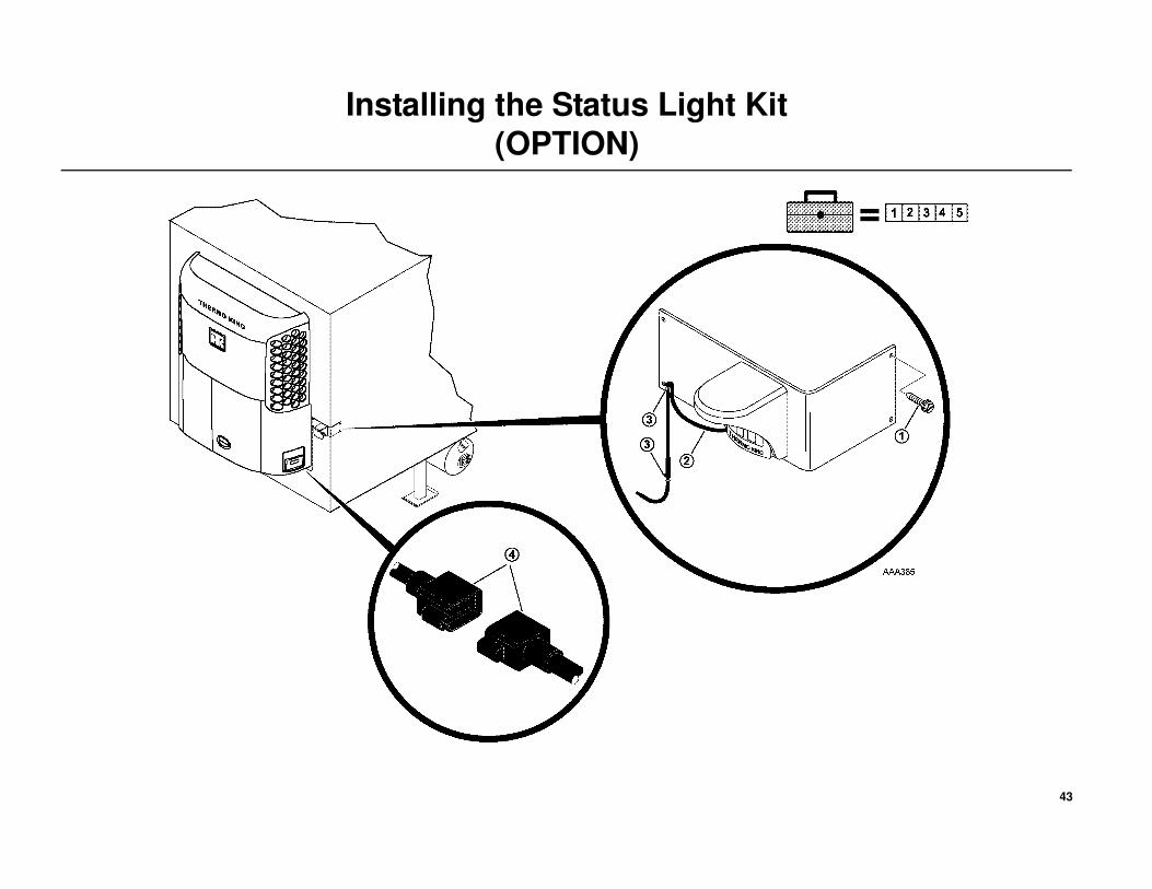
1. Mount the Status Light in a location so that is visible in the tractor
mirror to the driver. Mount securely with the provided screws.
2. Route harness as shown allowing a “drip-loop” to prevent water from
migrating into the Status Light.
3. Secure harness with clamps.
4. Connect to matching connector located behind the battery box and to
the left of the control box.
43
Installing the Status Light Kit
(OPTION)
44
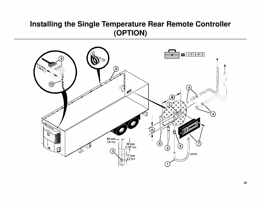
Installing the Single Temperature Rear Remote Controller
(OPTION)
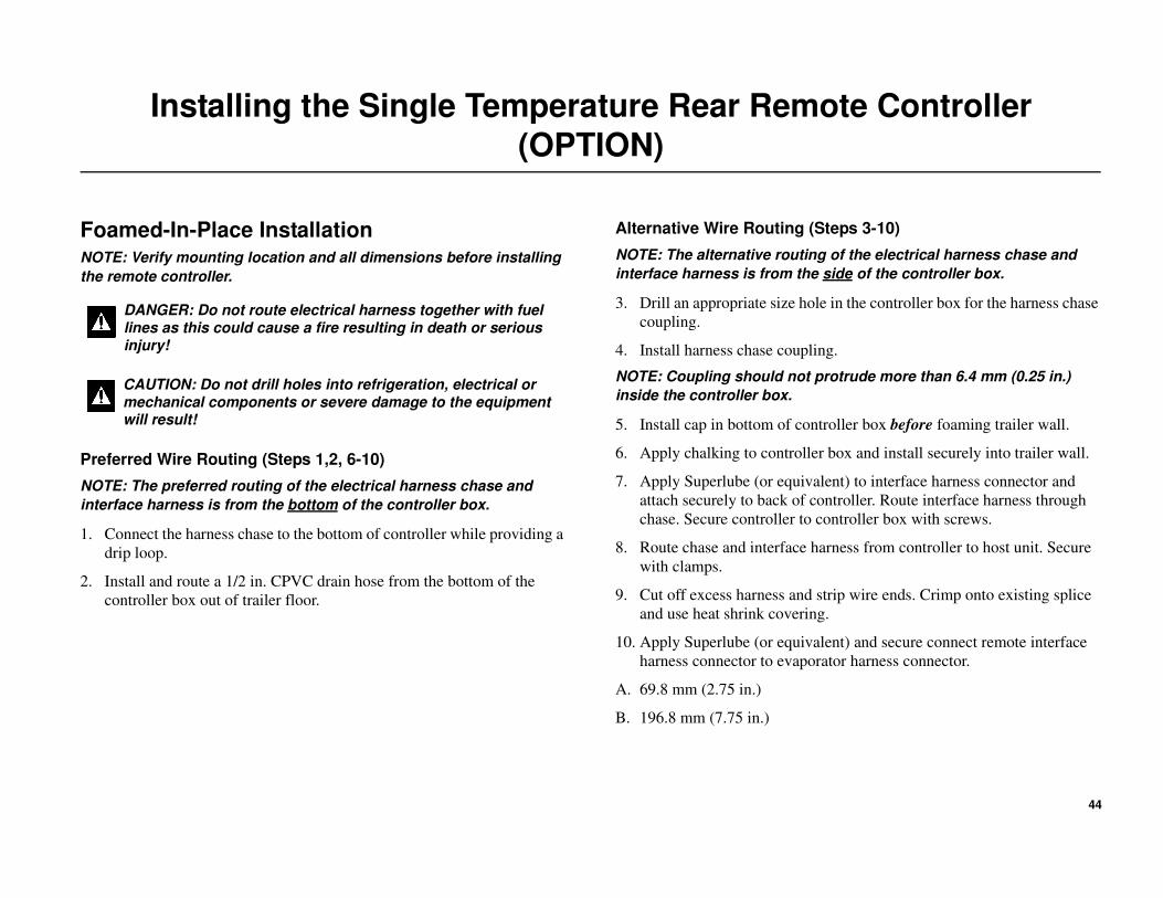
Foamed-In-Place InstallationNOTE: Verify mounting location and all dimensions before installing
the remote controller.
Preferred Wire Routing (Steps 1,2, 6-10)
NOTE: The preferred routing of the electrical harness chase and
interface harness is from the bottom of the controller box.
1. Connect the harness chase to the bottom of controller while providing a
drip loop.
2. Install and route a 1/2 in. CPVC drain hose from the bottom of the
controller box out of trailer floor.
Alternative Wire Routing (Steps 3-10)
NOTE: The alternative routing of the electrical harness chase and
interface harness is from the side of the controller box.
3. Drill an appropriate size hole in the controller box for the harness chase
coupling.
4. Install harness chase coupling.
NOTE: Coupling should not protrude more than 6.4 mm (0.25 in.)
inside the controller box.
5. Install cap in bottom of controller box before foaming trailer wall.
6. Apply chalking to controller box and install securely into trailer wall.
7. Apply Superlube (or equivalent) to interface harness connector and
attach securely to back of controller. Route interface harness through
chase. Secure controller to controller box with screws.
8. Route chase and interface harness from controller to host unit. Secure
with clamps.
9. Cut off excess harness and strip wire ends. Crimp onto existing splice
and use heat shrink covering.
10. Apply Superlube (or equivalent) and secure connect remote interface
harness connector to evaporator harness connector.
A. 69.8 mm (2.75 in.)
B. 196.8 mm (7.75 in.)
DANGER: Do not route electrical harness together with fuel lines as this could cause a fire resulting in death or serious injury!
CAUTION: Do not drill holes into refrigeration, electrical or mechanical components or severe damage to the equipment will result!
45
Installing the Single Temperature Rear Remote Controller
(OPTION)
46
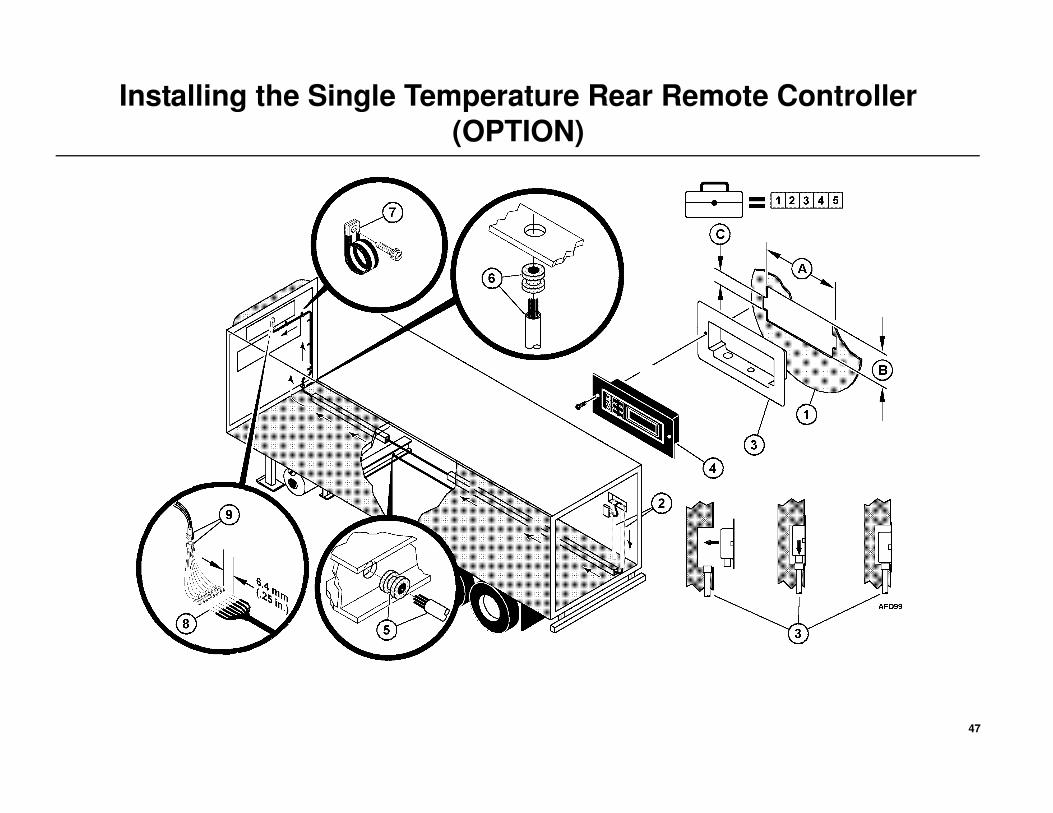
Installing the Single Temperature Rear Remote Controller
(OPTION)
Retro-Fit Installation
NOTE: Verify mounting location and all dimensions before installing
the remote controller.
1. Cut opening in trailer wall per dimensions shown.
2. Install and route a 1/2 in. CPVC drain hose and 0.88 O.D. harness
chase from the bottom of the controller box out of the trailer.
3. Apply caulking to controller box and install securely in trailer wall.
NOTE: Make sure the drain hose and harness chase are connected
properly.
4. Apply caulking to remote controller with interface connector harness,
route harness down chase and forward to unit.
5. Route harness under trailer through chase in floor or I-beam cross
members towards the unit.
6. From inside the trailer, measure and drill an appropriate size hole and
route the harness up into the trailer towards the unit.
7. Secure harness to the backside of the unit with clamps.
8. Measure the length of harness required to connect to host unit
evaporator harness connector, cut off excess harness and strip wire
ends. Crimp into existing splice and use heat shrink covering.
9. Securely connect the remote interface harness to the evaporator harness
connector.
A. 203 mm (8.0 in.)
B. 107.9 mm (4.25 in.)
C. 38 x 12.7 mm (1.5 x .5 in.)
DANGER: Do not route electrical harness together with fuel lines as this could cause a fire resulting in death or serious injury!
CAUTION: Do not drill holes into refrigeration, electrical or mechanical components or severe damage to the equipment will result!
CAUTION: Rubber grommets must be used when routing electrical harnesses through metal holes!
47
Installing the Single Temperature Rear Remote Controller
(OPTION)
48
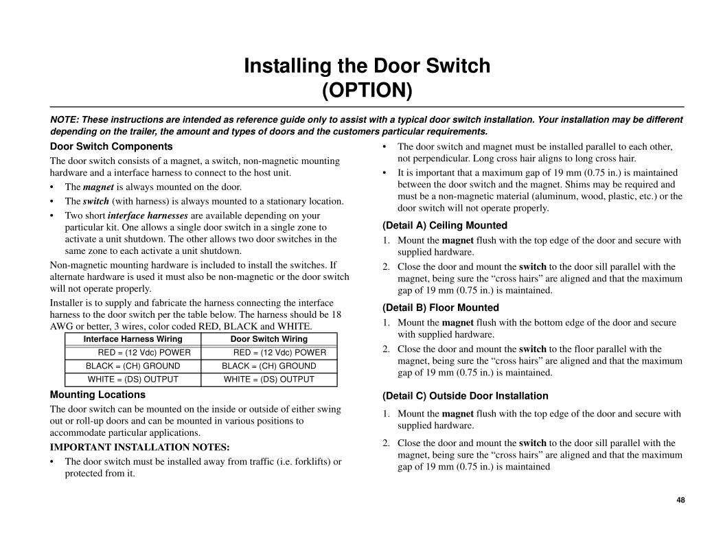
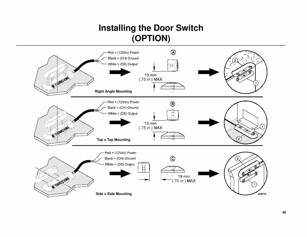
Installing the Door Switch
(OPTION)
NOTE: These instructions are intended as reference guide only to assist with a typical door switch installation. Your installation may be different
depending on the trailer, the amount and types of doors and the customers particular requirements.
Door Switch Components
The door switch consists of a magnet, a switch, non-magnetic mounting
hardware and a interface harness to connect to the host unit.
• The magnet is always mounted on the door.
• The switch (with harness) is always mounted to a stationary location.
• Two short interface harnesses are available depending on your
particular kit. One allows a single door switch in a single zone to
activate a unit shutdown. The other allows two door switches in the
same zone to each activate a unit shutdown.
Non-magnetic mounting hardware is included to install the switches. If
alternate hardware is used it must also be non-magnetic or the door switch
will not operate properly.
Installer is to supply and fabricate the harness connecting the interface
harness to the door switch per the table below. The harness should be 18
AWG or better, 3 wires, color coded RED, BLACK and WHITE.
Mounting Locations
The door switch can be mounted on the inside or outside of either swing
out or roll-up doors and can be mounted in various positions to
accommodate particular applications.
IMPORTANT INSTALLATION NOTES:
• The door switch must be installed away from traffic (i.e. forklifts) or
protected from it.
• The door switch and magnet must be installed parallel to each other,
not perpendicular. Long cross hair aligns to long cross hair.
• It is important that a maximum gap of 19 mm (0.75 in.) is maintained
between the door switch and the magnet. Shims may be required and
must be a non-magnetic material (aluminum, wood, plastic, etc.) or the
door switch will not operate properly.
(Detail A) Ceiling Mounted
1. Mount the magnet flush with the top edge of the door and secure with
supplied hardware.
2. Close the door and mount the switch to the door sill parallel with the
magnet, being sure the “cross hairs” are aligned and that the maximum
gap of 19 mm (0.75 in.) is maintained.
(Detail B) Floor Mounted
1. Mount the magnet flush with the bottom edge of the door and secure
with supplied hardware.
2. Close the door and mount the switch to the floor parallel with the
magnet, being sure the “cross hairs” are aligned and that the maximum
gap of 19 mm (0.75 in.) is maintained.
(Detail C) Outside Door Installation
1. Mount the magnet flush with the top edge of the door and secure with
supplied hardware.
2. Close the door and mount the switch to the door sill parallel with the
magnet, being sure the “cross hairs” are aligned and that the maximum
gap of 19 mm (0.75 in.) is maintained
Interface Harness Wiring Door Switch Wiring
RED = (12 Vdc) POWER RED = (12 Vdc) POWER
BLACK = (CH) GROUND BLACK = (CH) GROUND
WHITE = (DS) OUTPUT WHITE = (DS) OUTPUT
49
Installing the Door Switch
(OPTION)
Right Angle Mounting
Top x Top Mounting
Side x Side Mounting
50
Installing the Door Switch
(OPTION)
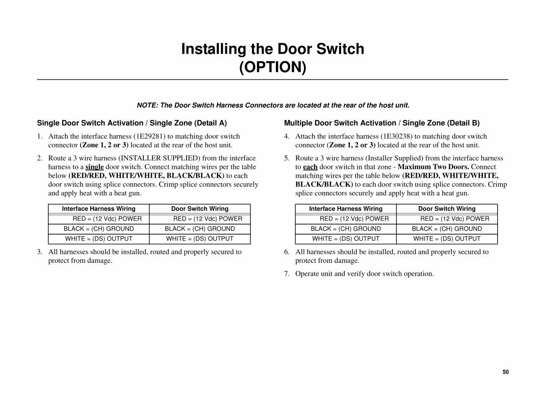
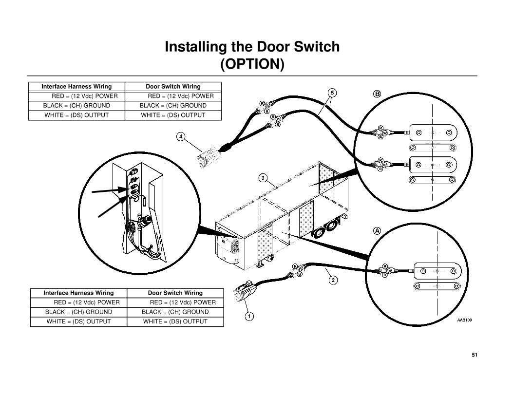
NOTE: The Door Switch Harness Connectors are located at the rear of the host unit.
Single Door Switch Activation / Single Zone (Detail A)
1. Attach the interface harness (1E29281) to matching door switch
connector (Zone 1, 2 or 3) located at the rear of the host unit.
2. Route a 3 wire harness (INSTALLER SUPPLIED) from the interface
harness to a single door switch. Connect matching wires per the table
below (RED/RED, WHITE/WHITE, BLACK/BLACK) to each
door switch using splice connectors. Crimp splice connectors securely
and apply heat with a heat gun.
3. All harnesses should be installed, routed and properly secured to
protect from damage.
Multiple Door Switch Activation / Single Zone (Detail B)
4. Attach the interface harness (1E30238) to matching door switch
connector (Zone 1, 2 or 3) located at the rear of the host unit.
5. Route a 3 wire harness (Installer Supplied) from the interface harness
to each door switch in that zone - Maximum Two Doors. Connect
matching wires per the table below (RED/RED, WHITE/WHITE,
BLACK/BLACK) to each door switch using splice connectors. Crimp
splice connectors securely and apply heat with a heat gun.
6. All harnesses should be installed, routed and properly secured to
protect from damage.
7. Operate unit and verify door switch operation.
Interface Harness Wiring Door Switch Wiring
RED = (12 Vdc) POWER RED = (12 Vdc) POWER
BLACK = (CH) GROUND BLACK = (CH) GROUND
WHITE = (DS) OUTPUT WHITE = (DS) OUTPUT
Interface Harness Wiring Door Switch Wiring
RED = (12 Vdc) POWER RED = (12 Vdc) POWER
BLACK = (CH) GROUND BLACK = (CH) GROUND
WHITE = (DS) OUTPUT WHITE = (DS) OUTPUT
51
Installing the Door Switch
(OPTION)
Interface Harness Wiring Door Switch Wiring
RED = (12 Vdc) POWER RED = (12 Vdc) POWER
BLACK = (CH) GROUND BLACK = (CH) GROUND
WHITE = (DS) OUTPUT WHITE = (DS) OUTPUT
Interface Harness Wiring Door Switch Wiring
RED = (12 Vdc) POWER RED = (12 Vdc) POWER
BLACK = (CH) GROUND BLACK = (CH) GROUND
WHITE = (DS) OUTPUT WHITE = (DS) OUTPUT

52
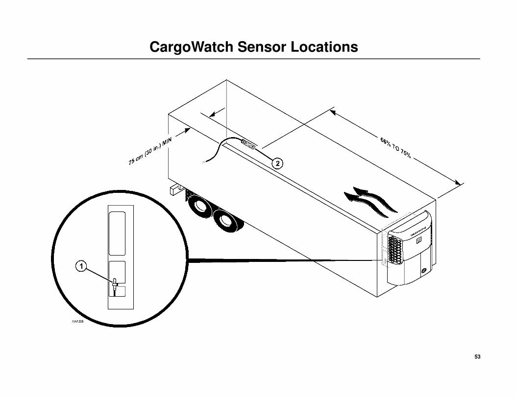
CargoWatch Sensor Locations
Sensor Location Recommendations
European Applications
Each cargo area requires a minimum of two sensors.
1. Sensor #1 located in the evaporator side return opening near unit return
air sensor (factory installed).
2. Sensor #2 located in the roof area 66% to 75% of the full length of the
cargo area (determined by installer).
Domestic Applications
As required by customer.
53
CargoWatch Sensor Locations

54
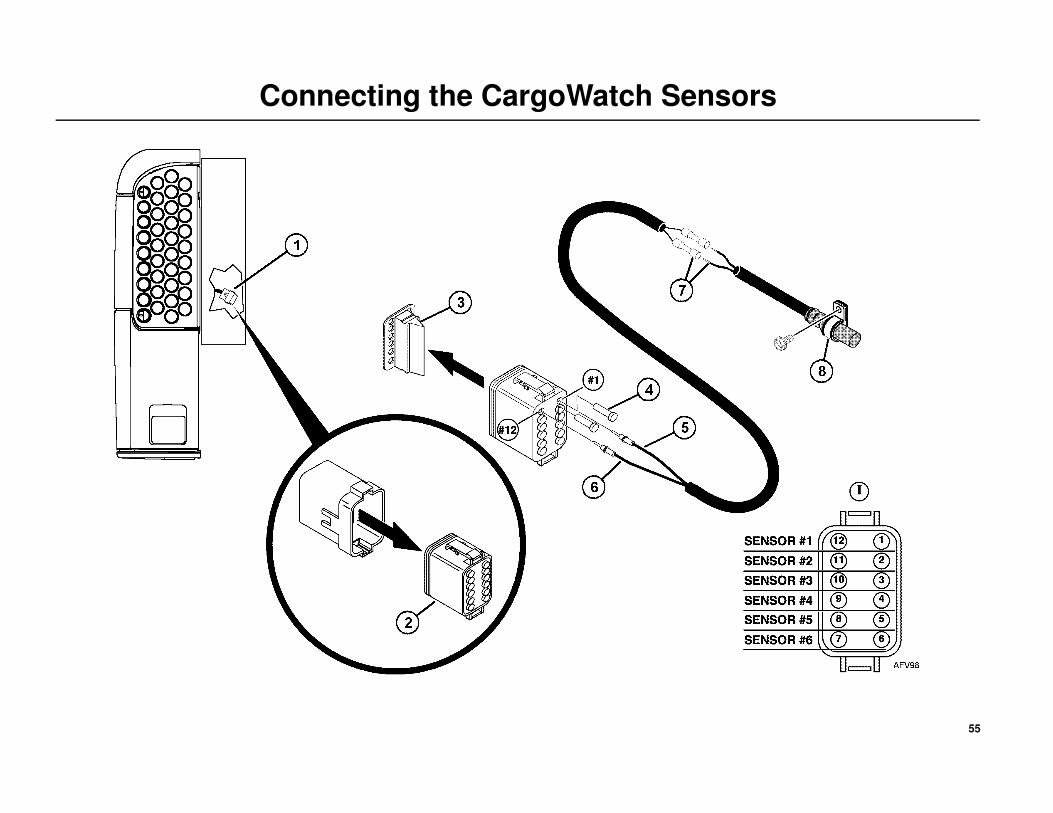
Connecting the CargoWatch Sensors
CONNECTING SENSORS
1. Locate the Sensor Interconnect Harness behind the evaporator access
panel.
2. Unplug the connector from the harness.
3. Removes orange end from connector.
4. Remove only the plugs from the connector holes for the sensors you are
connecting. Unused holes must remain plugged.
5. Insert WHITE pin connector and wire into correct connection until it
locks into position (Detail I). The wire side of the connector is shown.
6. Insert BLACK pin connector and wire into correct connection until it
locks into position (Detail I). The wire side of the connector is shown.
Reinstall orange end (3) back onto connector (2), apply a light coating
of Superlube to electrical connections and plug sensor back into mating
connector on the Sensor Interconnect Harness (1).
7. Connect the Sensor Interconnect Harness to the sensor using the splice
connectors. Crimp splice connectors securely and apply heat with a
heat gun.
8. Secure sensor with appropriate clamps.
SENSOR PLUGS
1 #1 and #12
2 #2 and #11
3 #3 and #10
4 #4 and #9
5 #5 and #8
6 #6 and #7
SENSOR PLUGS
1 White into #1
2 White into #2
3 White into #3
4 White into #4
5 White into #5
6 White into #6
SENSOR PLUGS
1 Black into #12
2 Black into #11
3 Black into #10
4 Black into #9
5 Black into #8
6 Black into #7
55
Connecting the CargoWatch Sensors
56
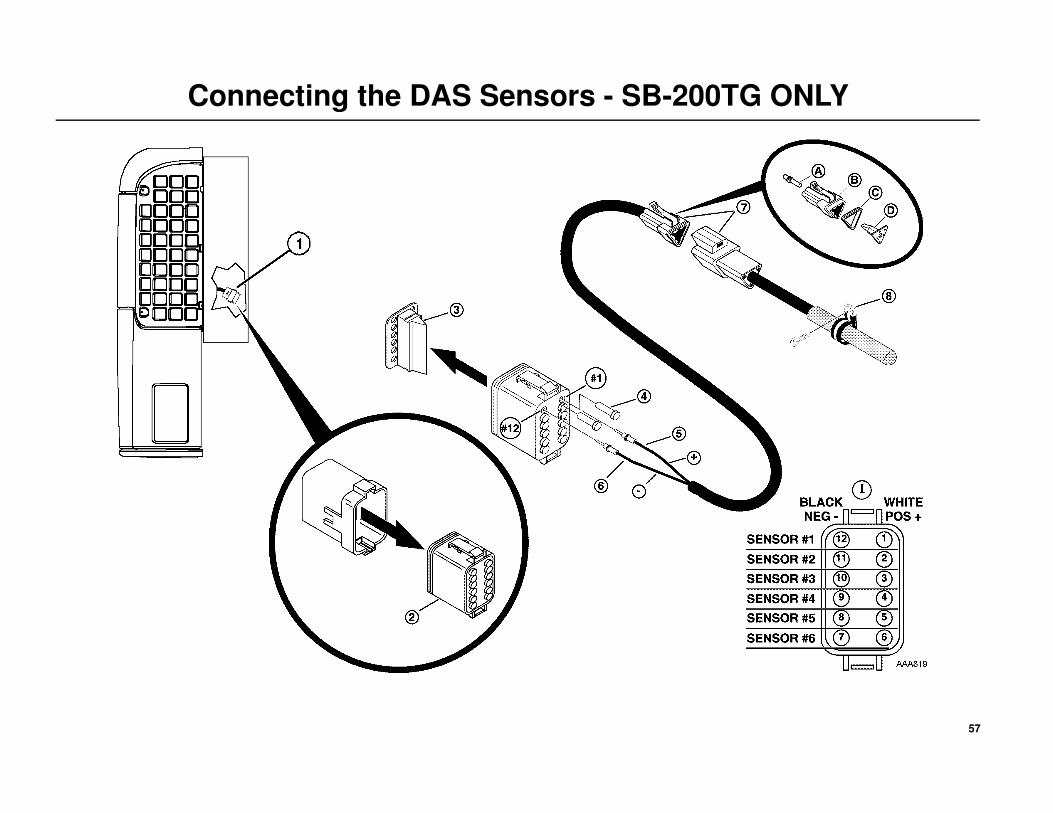
Connecting the DAS Sensors - SB-200TG ONLY
CONNECTING SENSORS
NOTE: All sensor harness wires are coded WHITE (POS+) and
BLACK (NEG-). Each sensor must be connected correctly or the DAS
will not function correctly.
1. Locate the Sensor Interconnect Harness behind the evaporator access
panel.
2. Unplug the connector from the harness.
3. Carefully remove orange end from connector.
4. Remove only the plugs from the connector holes for the sensors you are
connecting. Unused holes must remain plugged.
1. Insert WHITE (POS+) pin connector and wire into correct connection
until it locks into position (Detail I). The wire side of the connector is
shown.
2. Insert BLACK (NEG-) pin connector and wire into correct connection
until it locks into position (Detail I). The wire side of the connector is
shown.
Reinstall orange end (3) back onto connector (2), apply a light coating
of Superlube to electrical connections and plug sensor back into mating
connector on the Sensor Interconnect Harness (1).
3. Apply a light coating of Superlube to electrical connections and plug
each sensor into correct mating connector.
Secure sensor with appropriate clamps.
A = Terminal Pin
B = Connector Body
C = Sealing Boot
D = Connector Wedge
SENSOR PLUGS
1 #1 and #12
2 #2 and #11
3 #3 and #10
4 #4 and #9
5 #5 and #8
6 #6 and #7
SENSOR PLUGS
1 White into #1
2 White into #2
3 White into #3
4 White into #4
5 White into #5
6 White into #6
SENSOR PLUGS
1 Black into #12
2 Black into #11
3 Black into #10
4 Black into #9
5 Black into #8
6 Black into #7
SENSOR PLUGS
57
Connecting the DAS Sensors - SB-200TG ONLY
58
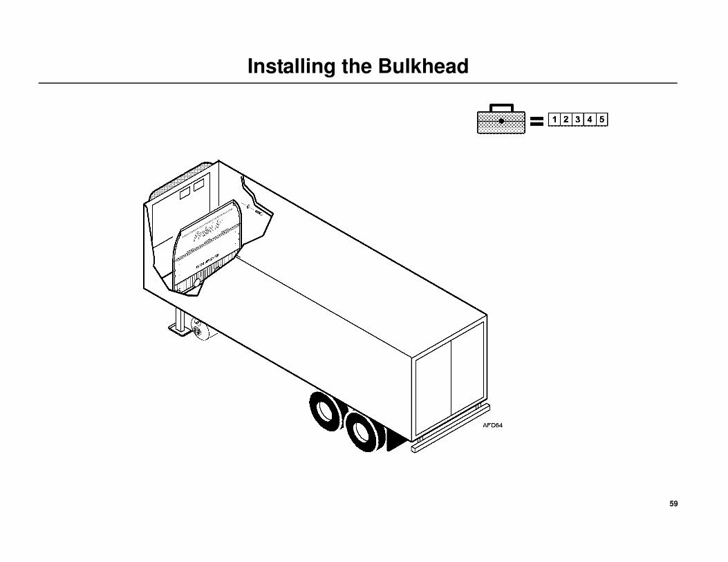
Installing the Bulkhead
THERMO KING RECOMMENDS USING A BULKHEAD
Bulkheads are available from authorized Thermo King dealers.
Return Airflow
Restrictions of the return airflow adversely affects the performance of the
unit. The area directly behind the evaporator return air inlet must not be
restricted.
Bulkhead Function
A bulkhead is used to keep the return airflow from being restricted if the
load shifts. The bulkhead also prevents the load from shifting into the
return airflow passageway on the front wall of the trailer.
Typical Bulkhead Shown
Follow bulkhead manufacturer specific details for proper installation and
recommendations.
CAUTION: Do not drill holes into refrigeration, electrical or mechanical components or severe damage to the equipment will result!
59
Installing the Bulkhead
60
Installing the Battery
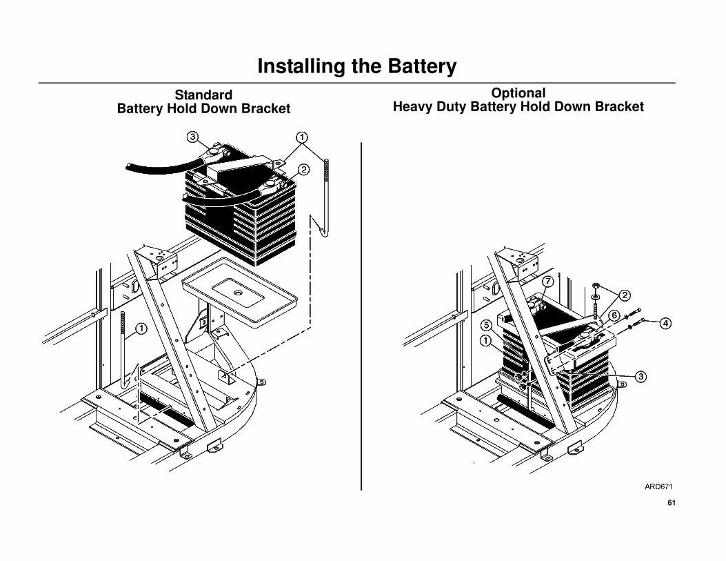
Standard Battery Hold Down Bracket
1. Install battery into the tray and secure with hold down bracket and rods.
Tighten the two battery hold down rods to 2.25 N•m (20 in -lbs.)
DO NOT over tighten as this may crack or distort the battery!
NOTE: One of the hold down rods must fit into the notch located on
the channel under the battery. You may have to move the electrical
harness slightly to access this notch.
2. Install positive + battery cable on the positive battery post first to
minimize accidental electrical shorting.
3. Install negative - battery cable on negative battery post second to
minimize accidental electrical shorting.
Optional Heavy Duty Battery Hold Down Bracket
1. Install the battery into the tray.
2. Install the battery hold down bracket and rods. Loosely install hardware
onto the rods.
NOTE: One of the hold down rods must fit into the notch located on
the channel under the battery. You may have to move the electrical
harness slightly to access this notch.
3. Align the tab of the battery hold down bracket over the two existing
holes in the frame support channel.
NOTE: Units built prior to March 2010 will require the two existing
holes in the frame support channel be drilled completely through the
channel using a 0.266 dia. (H) drill bit.
4. Install the two mounting bolts and flat washers through the hold down
bracket and support channel. Install the flat washers and locking nuts
and torque hardware to 13.5 N•m (120 in-lbs).
5. Tighten the two battery hold down rods to 2.25 N•m (20 in -lbs.)
DO NOT over tighten as this may crack or distort the battery!
6. Install positive + battery cable on the positive battery post first to
minimize accidental electrical shorting.
7. Install negative - battery cable on negative battery post second to
minimize accidental electrical shorting.
CAUTION: Set all electrical controls to the OFF position before connecting the battery to prevent the unit from starting!
CAUTION: Always wear protective clothing, gloves and eye wear when handling and installing batteries!
CAUTION: Cover battery terminals to prevent accidental shorting during battery installation!
61
Installing the Battery
Standard Battery Hold Down Bracket
Optional Heavy Duty Battery Hold Down Bracket
62
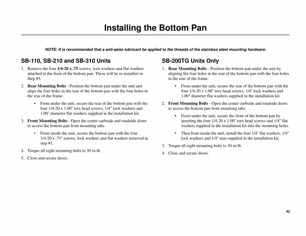
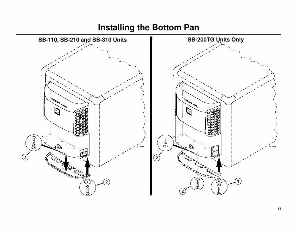
Installing the Bottom Pan
NOTE: It is recommended that a anti-seize lubricant be applied to the threads of the stainless steel mounting hardware.
SB-110, SB-210 and SB-310 Units
1. Remove the four 1/4-20 x .75 screws, lock washers and flat washers
attached to the front of the bottom pan. These will be re-installed in
Step #3.
2. Rear Mounting Bolts - Position the bottom pan under the unit and
align the four holes in the rear of the bottom pan with the four holes in
the rear of the frame.
• From under the unit, secure the rear of the bottom pan with the
four 1/4-20 x 1.00'' torx head screws, 1/4” lock washers and
1.00'' diameter flat washers supplied in the installation kit.
3. Front Mounting Bolts - Open the center curbside and roadside doors
to access the bottom pan front mounting tabs.
• From inside the unit, secure the bottom pan with the four
1/4-20 x .75'' screws, lock washers and flat washers removed in
step #1.
4. Torque all eight mounting bolts to 30 in-lb.
5. Close and secure doors.
SB-200TG Units Only
1. Rear Mounting Bolts - Position the bottom pan under the unit by
aligning the four holes in the rear of the bottom pan with the four holes
in the rear of the frame.
• From under the unit, secure the rear of the bottom pan with the
four 1/4-20 x 1.00'' torx head screws, 1/4'' lock washers and
1.00'' diameter flat washers supplied in the installation kit.
2. Front Mounting Bolts - Open the center curbside and roadside doors
to access the bottom pan front mounting tabs.
• From under the unit, secure the front of the bottom pan by
inserting the four 1/4-20 x 1.00'' torx head screws and 1/4'' flat
washers supplied in the installation kit into the mounting holes.
• Then from inside the unit, install the four 1/4'' flat washers, 1/4''
lock washers and 1/4'' nuts supplied in the installation kit.
3. Torque all eight mounting bolts to 30 in-lb.
4. Close and secure doors.
63
Installing the Bottom Pan
SB-110, SB-210 and SB-310 Units SB-200TG Units Only
64
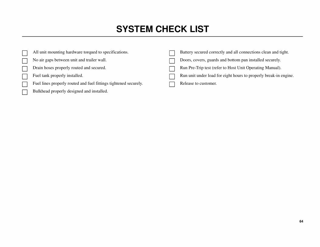
SYSTEM CHECK LIST
All unit mounting hardware torqued to specifications.
No air gaps between unit and trailer wall.
Drain hoses properly routed and secured.
Fuel tank properly installed.
Fuel lines properly routed and fuel fittings tightened securely.
Bulkhead properly designed and installed.
Battery secured correctly and all connections clean and tight.
Doors, covers, guards and bottom pan installed securely.
Run Pre-Trip test (refer to Host Unit Operating Manual).
Run unit under load for eight hours to properly break-in engine.
Release to customer.
65
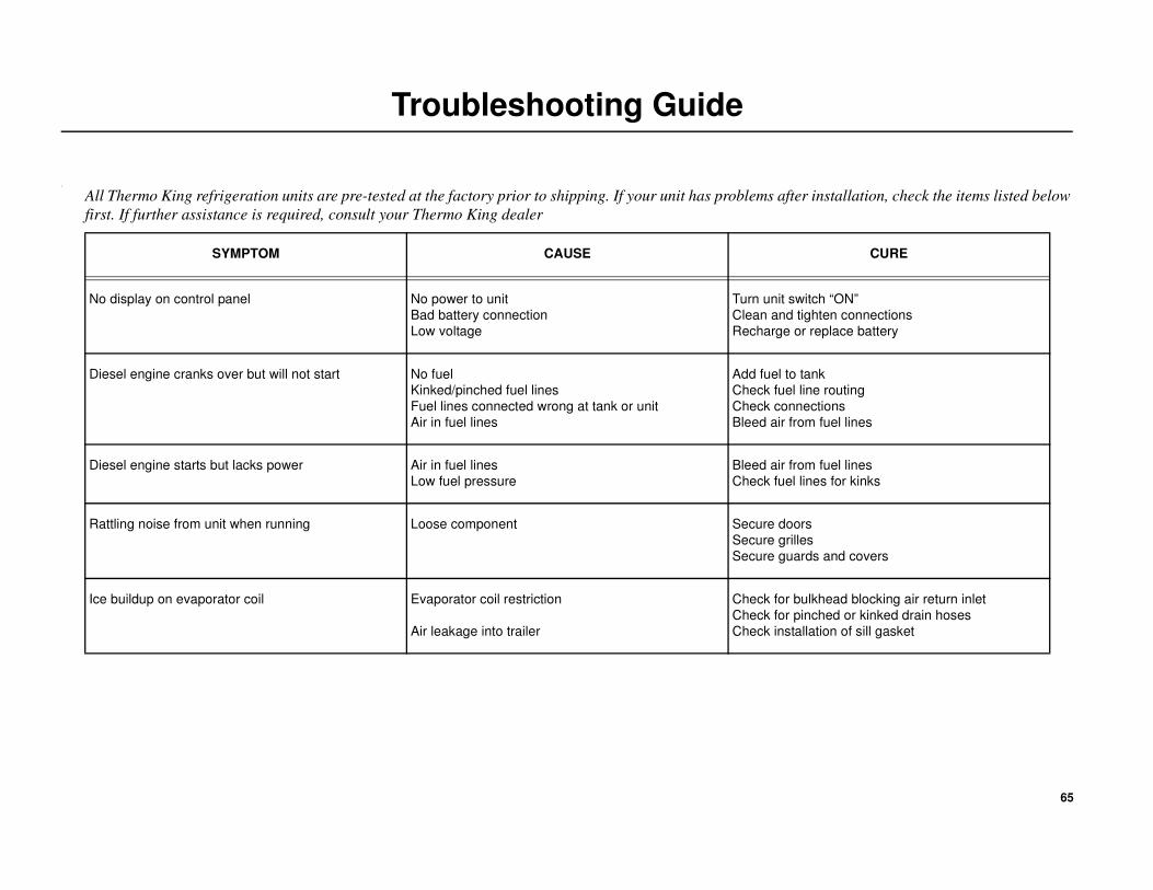
Troubleshooting Guide
.
All Thermo King refrigeration units are pre-tested at the factory prior to shipping. If your unit has problems after installation, check the items listed below
first. If further assistance is required, consult your Thermo King dealer
SYMPTOM CAUSE CURE
No display on control panel No power to unit
Bad battery connection
Low voltage
Turn unit switch “ON”
Clean and tighten connections
Recharge or replace battery
Diesel engine cranks over but will not start No fuel
Kinked/pinched fuel lines
Fuel lines connected wrong at tank or unit
Air in fuel lines
Add fuel to tank
Check fuel line routing
Check connections
Bleed air from fuel lines
Diesel engine starts but lacks power Air in fuel lines
Low fuel pressure
Bleed air from fuel lines
Check fuel lines for kinks
Rattling noise from unit when running Loose component Secure doors
Secure grilles
Secure guards and covers
Ice buildup on evaporator coil Evaporator coil restriction
Air leakage into trailer
Check for bulkhead blocking air return inlet
Check for pinched or kinked drain hoses
Check installation of sill gasket

66
Recommended