Installation and Operation Manual Rev A
SGI 225 SGI 250 SGI 266 SGI 300 SGI 500
INSTALLATION AND OPERATION MANUAL Revision A
© 2010, Solectria Renewables LLC
SGI Series Inverters
Installation and Operation Manual (Rev A) 2
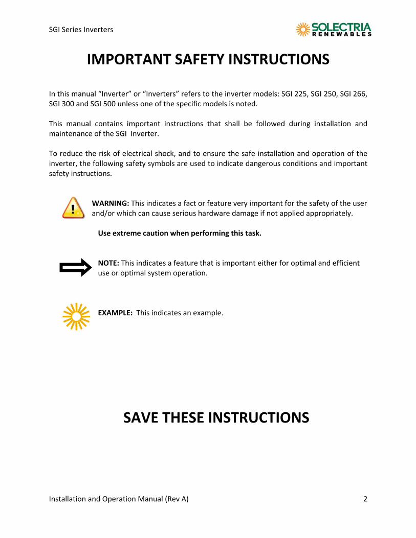
IMPORTANT SAFETY INSTRUCTIONS In this manual “Inverter” or “Inverters” refers to the inverter models: SGI 225, SGI 250, SGI 266, SGI 300 and SGI 500 unless one of the specific models is noted. This manual contains important instructions that shall be followed during installation and maintenance of the SGI Inverter. To reduce the risk of electrical shock, and to ensure the safe installation and operation of the inverter, the following safety symbols are used to indicate dangerous conditions and important safety instructions.
WARNING: This indicates a fact or feature very important for the safety of the user and/or which can cause serious hardware damage if not applied appropriately. Use extreme caution when performing this task.
NOTE: This indicates a feature that is important either for optimal and efficient
use or optimal system operation.
EXAMPLE: This indicates an example.
SAVE THESE INSTRUCTIONS
SGI Series Inverters
Installation and Operation Manual (Rev A) 3
IMPORTANT SAFETY INSTRUCTIONS
All electrical installations shall be performed in accordance with the local, American and Canadian electrical codes ANSI/NFPA 70.
The Inverter contains no user serviceable parts. Please contact Solectria Renewables or a Solectria Renewables authorized system installer for maintenance. (Appendix C for Solectria Renewables contact information and authorized system installers.)
Before installing or using the Inverter, please read all instructions and caution markings in this manual and on the Inverter unit as well as the PV modules.
Connection of the Inverter to the electric utility grid must be completed after receiving prior approval from the utility company (unless connection agreement) and must only be performed by qualified personnel.
Completely cover the surface of all PV‐arrays with opaque (dark) material before wiring them. PV arrays produce electrical energy when exposed to light and could create a hazardous condition.
The inverter enclosure and disconnects must be locked (requiring a tool or key for access) for protection against risk of injury to persons. The enclosure includes a lockable handle and comes with a key. Keep the key in a safe location in case access to the cabinet is needed. (A replacement for a lost key can be purchased from Solectria Renewables.)
SAVE THESE INSTRUCTIONS
PRESCRIPTIONS DE SECURITE IMPORTANTES
Tous les travaux d’installation électrique doivent être exécutés en conformité aux normes électriques locales ainsi qu’à la norme nationale américaine et canadienne ANSI/NFPA 70.
Le SGI ne contient aucune pièce requérant un entretient effectué par l‘utilisateur. Pour toute maintenance, veuillez consulter Solectria Renewables ou un installateur agréé par Solectria Renewables (les coordonnées de Solectria Renewables et des installateurs agréés sont indiquées sur le site web de Solectria Renewables: www.solren.com.
Avant d’installer ou d’utiliser le SGI, veuillez lire toutes instructions et toutes les mises en garde présentes dans ce manuel, sur le SGI et sur les modules PV.
Le raccordement du SGI au réseau électrique ne doit être effectuée qu’après avoir obtenu une entente d’interconnexion auprès de la compagnie locale de distribution électrique et uniquement par du personnel autorisé et qualifié.
La surface de tous les capteurs PV doivent être recouverte entièrement d’un matériel opaque
(noir) avant de procéder au câblage. Les capteurs PV exposés a la lumière produisent du courant électrique susceptible de créer une situation de risque.
CONSERVEZ CES INSTRUCTIONS
SGI Series Inverters
Installation and Operation Manual (Rev A) 4
Table of Contents
1 Introduction………………………………………………………………..…………… 5 2 Site Preparation and Inverter Placement..……………………..………… 7
2.1 Inverter Positioning……..…………………………………...……… 9 2.2 Mounting Details.……………………………………………..……… 10 2.3 DC and AC Wire Entry Points. …………………………………… 11
3 Installation………………………………….……………………………………………. 12 3.1 Checking for Shipping Damage…………………………………. 12 3.2 Inverter Mounting……………………………………………………. 13
4 Electrical Connections and Connecting to Grid.……………………..…. 16 4.1 Grounding Electrode Conductor……………………………….. 16 4.2 DC Wiring…..……………………………………………………………… 17 4.3 DC Ground Fault Detection and Interruption…………….. 21 4.4 AC Wiring………………………………………………………………….. 22 4.5 Connection to Electric Utility Grid……………………………… 22 4.6 AC Ground Fault Detection………………………………………... 24 4.7 Lightning and Surge Protection………………………………….. 24 4.8 SolrenView Monitoring………………………………………….…… 25
5 Commissioning the Inverter…………………..………….………………....…… 26 5.1 Turning on the inverter………………………………………………. 26 5.2 Operation…………………………………………………………………… 26
6 Display and LED……………………..………………………………..………………… 27 6.1 LCD Display………………………………………………………………… 27 6.2 LED Lights…………………………………………………………………… 30
7 Troubleshooting and LCD messages…………………………………………… 31 8 Warranty and RMA Policy.…………………………………..…………….…….… 33 8.1 Warranty Policy………………………………………………………….. 33 8.2 Return Material Policy………………………………………………… 37 9 Technical Data.…………………………………………………………………...……… 38
9.1 DC Input……………………………………………………………………… 38 9.2 AC Output…………………..…………………………………….………… 40 9.3 Other Specifications……………………………………………………. 40
10 Appendix A Data sheet link …….……………………………..…………...……… 43 Appendix B String Sizing link C ……............................................…… 43 Appendix C Contact Information…..……………………….……………….…… 43
Appendix D UL1741/CSA22.2 Listing Letter ………………………………… 44
SGI Series Inverters
Installation and Operation Manual (Rev A) 5
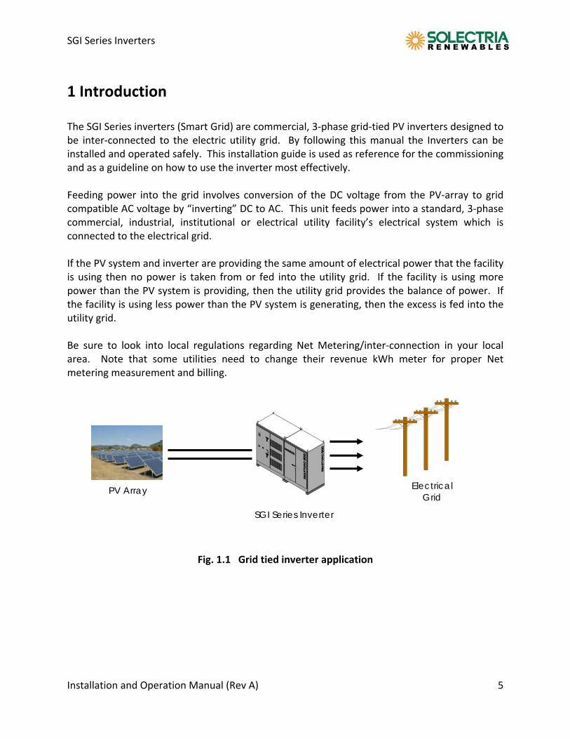
1 Introduction The SGI Series inverters (Smart Grid) are commercial, 3‐phase grid‐tied PV inverters designed to be inter‐connected to the electric utility grid. By following this manual the Inverters can be installed and operated safely. This installation guide is used as reference for the commissioning and as a guideline on how to use the inverter most effectively. Feeding power into the grid involves conversion of the DC voltage from the PV‐array to grid compatible AC voltage by “inverting” DC to AC. This unit feeds power into a standard, 3‐phase commercial, industrial, institutional or electrical utility facility’s electrical system which is connected to the electrical grid. If the PV system and inverter are providing the same amount of electrical power that the facility is using then no power is taken from or fed into the utility grid. If the facility is using more power than the PV system is providing, then the utility grid provides the balance of power. If the facility is using less power than the PV system is generating, then the excess is fed into the utility grid. Be sure to look into local regulations regarding Net Metering/inter‐connection in your local area. Note that some utilities need to change their revenue kWh meter for proper Net metering measurement and billing.
Fig. 1.1 Grid tied inverter application
PV Array
SGI Series Inverter
Electrical Grid
SGI Series Inverters
Installation and Operation Manual (Rev A) 6
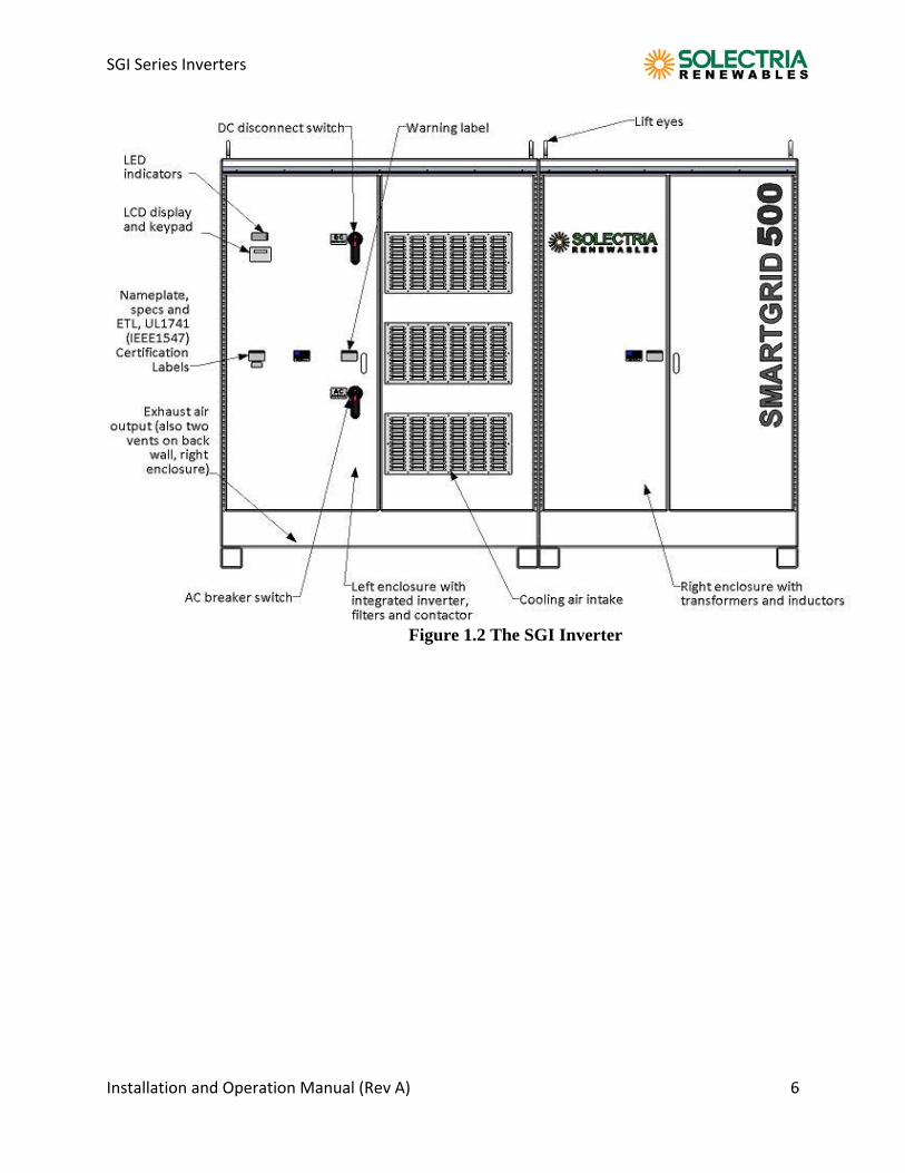
Figure 1.2 The SGI Inverter
SGI Series Inverters
Installation and Operation Manual (Rev A) 7
2.0 Site Preparation and Inverter Placement The Inverter is comprised of a rainproof industrial enclosure containing electrical and electronic components and AC and DC integrated disconnects.
NOTE: If the Inverter is mounted outside, please make sure the enclosure doors remain closed during the installation process in case of rain or snow. (Leaving these doors open voids the warranty.)
Criteria for device mounting:
Because the power electronics are within the rainproof main enclosure, the inverter can be mounted outdoors.
The maximum life for the inverter can be achieved by mounting the unit in a clean, dry and cool location.
For optimal electrical system efficiency, use the shortest possible AC and DC cables and use the maximum allowable cable size.
Avoid installation in close proximity to people or animals, as there is audible high‐frequency switching noise.
Install the inverter in an accessible location following NEC codes for enclosure and disconnect door clearances and proximity to other equipment.
For optimal inverter life and performance, do not mount the inverter in direct sunlight, especially in hot climates, although the inverter is designed to function at full power continuously in up to 50oC ambient temperatures. In hot climates if the unit must be mounted in direct sunlight a metal sun‐shield is recommended. It is recommended that the inverter is mounted on the north side of buildings or on the north side of a ground mount PV array . It is also recommended to face to door north or east if possible.
SGI Series Inverters
Installation and Operation Manual (Rev A) 8
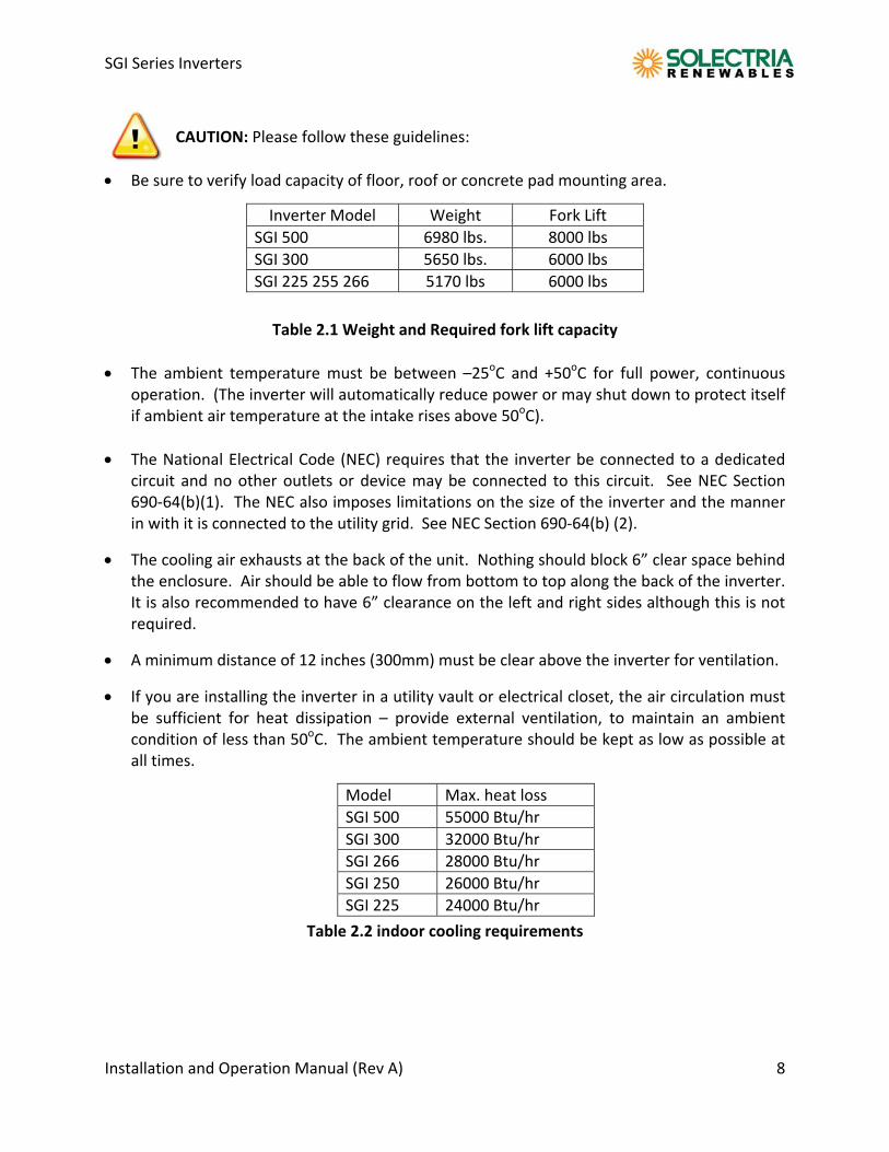
CAUTION: Please follow these guidelines:
Be sure to verify load capacity of floor, roof or concrete pad mounting area.
Table 2.1 Weight and Required fork lift capacity
The ambient temperature must be between –25oC and +50oC for full power, continuous operation. (The inverter will automatically reduce power or may shut down to protect itself if ambient air temperature at the intake rises above 50oC).
The National Electrical Code (NEC) requires that the inverter be connected to a dedicated circuit and no other outlets or device may be connected to this circuit. See NEC Section 690‐64(b)(1). The NEC also imposes limitations on the size of the inverter and the manner in with it is connected to the utility grid. See NEC Section 690‐64(b) (2).
The cooling air exhausts at the back of the unit. Nothing should block 6” clear space behind the enclosure. Air should be able to flow from bottom to top along the back of the inverter. It is also recommended to have 6” clearance on the left and right sides although this is not required.
A minimum distance of 12 inches (300mm) must be clear above the inverter for ventilation.
If you are installing the inverter in a utility vault or electrical closet, the air circulation must be sufficient for heat dissipation – provide external ventilation, to maintain an ambient condition of less than 50oC. The ambient temperature should be kept as low as possible at all times.
Table 2.2 indoor cooling requirements
Inverter Model Weight Fork Lift
SGI 500 6980 lbs. 8000 lbs
SGI 300 5650 lbs. 6000 lbs
SGI 225 255 266 5170 lbs 6000 lbs
Model Max. heat loss
SGI 500 55000 Btu/hr
SGI 300 32000 Btu/hr
SGI 266 28000 Btu/hr
SGI 250 26000 Btu/hr
SGI 225 24000 Btu/hr
SGI Series Inverters
Installation and Operation Manual (Rev A) 9
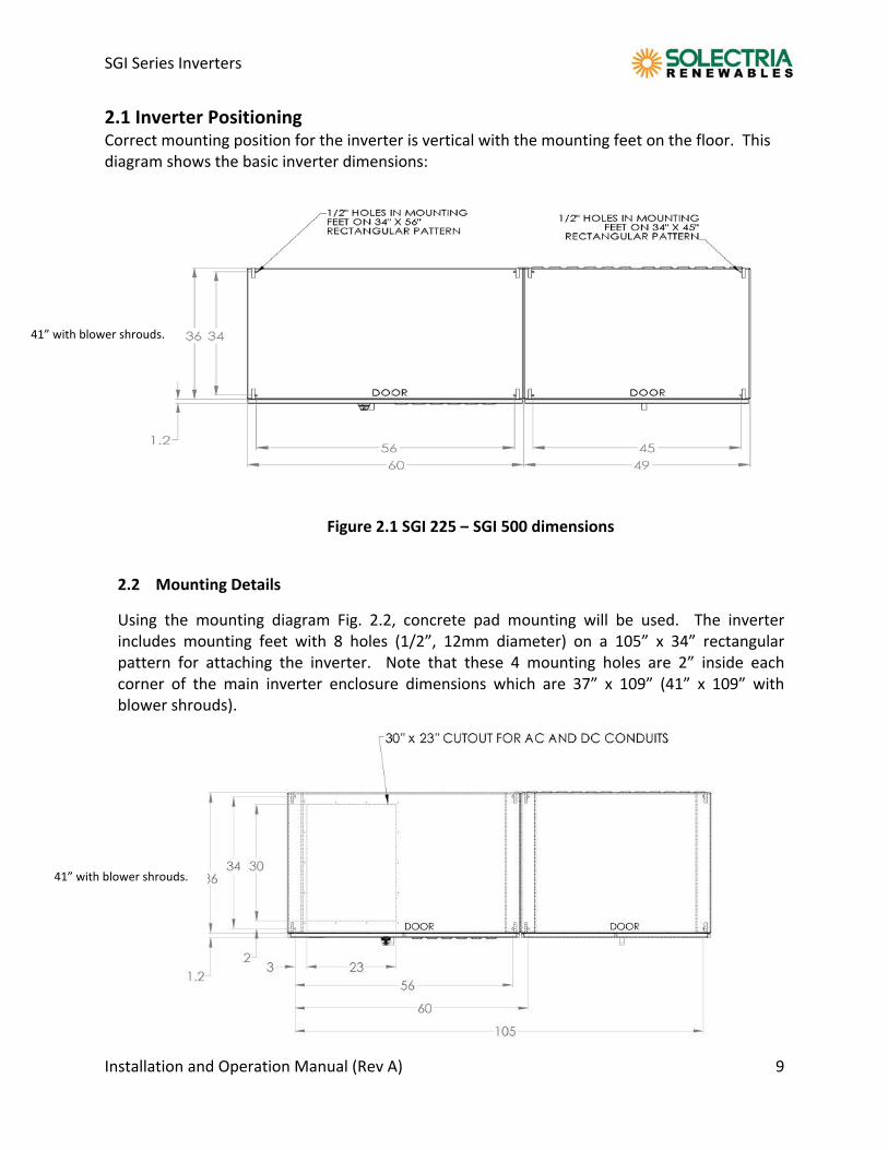
2.1 Inverter Positioning Correct mounting position for the inverter is vertical with the mounting feet on the floor. This diagram shows the basic inverter dimensions:
2.2 Mounting Details
Using the mounting diagram Fig. 2.2, concrete pad mounting will be used. The inverter includes mounting feet with 8 holes (1/2”, 12mm diameter) on a 105” x 34” rectangular pattern for attaching the inverter. Note that these 4 mounting holes are 2” inside each corner of the main inverter enclosure dimensions which are 37” x 109” (41” x 109” with blower shrouds).
Figure 2.1 SGI 225 – SGI 500 dimensions
41” with blower shrouds.
41” with blower shrouds.
SGI Series Inverters
Installation and Operation Manual (Rev A) 10
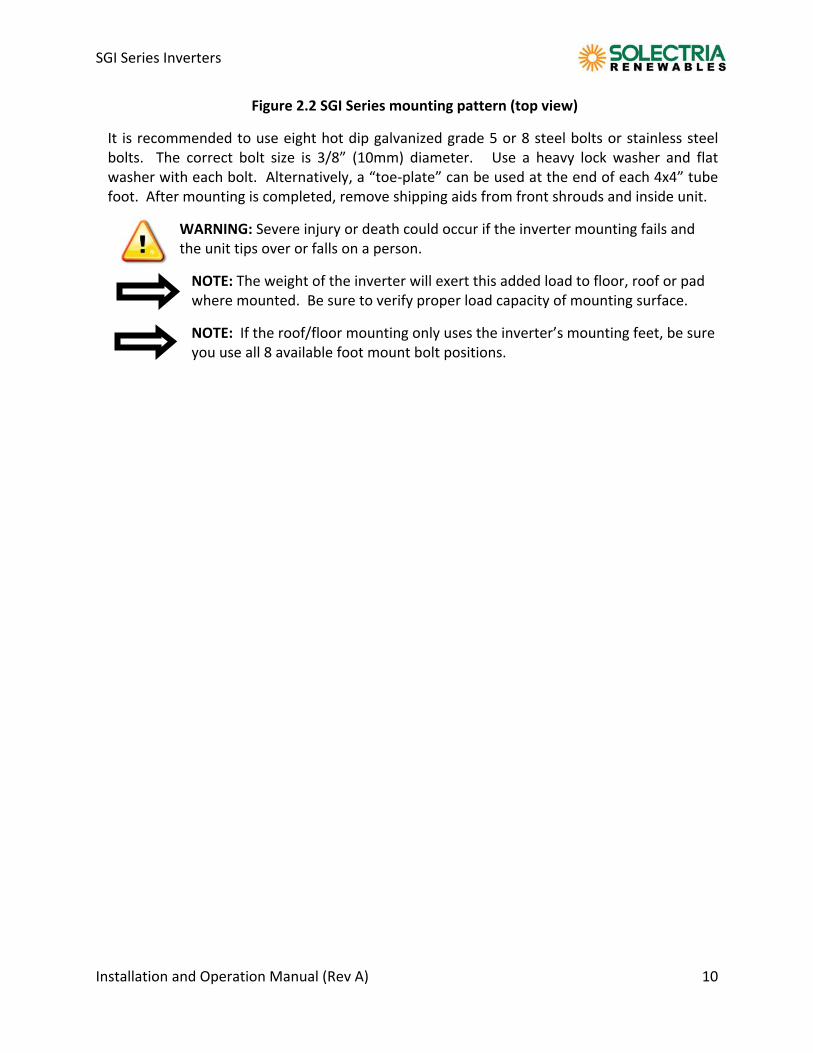
Figure 2.2 SGI Series mounting pattern (top view)
It is recommended to use eight hot dip galvanized grade 5 or 8 steel bolts or stainless steel bolts. The correct bolt size is 3/8” (10mm) diameter. Use a heavy lock washer and flat washer with each bolt. Alternatively, a “toe‐plate” can be used at the end of each 4x4” tube foot. After mounting is completed, remove shipping aids from front shrouds and inside unit.
WARNING: Severe injury or death could occur if the inverter mounting fails and the unit tips over or falls on a person.
NOTE: The weight of the inverter will exert this added load to floor, roof or pad where mounted. Be sure to verify proper load capacity of mounting surface.
NOTE: If the roof/floor mounting only uses the inverter’s mounting feet, be sure you use all 8 available foot mount bolt positions.
SGI Series Inverters
Installation and Operation Manual (Rev A) 11
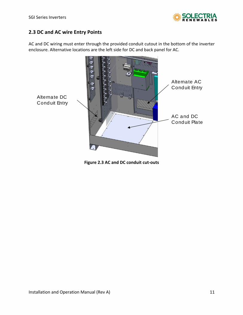
2.3 DC and AC wire Entry Points AC and DC wiring must enter through the provided conduit cutout in the bottom of the inverter enclosure. Alternative locations are the left side for DC and back panel for AC.
Figure 2.3 AC and DC conduit cut‐outs
AC and DC Conduit Plate
Alternate AC Conduit Entry
Alternate DC Conduit Entry
SGI Series Inverters
Installation and Operation Manual (Rev A) 12
3.0 Installation WARNING: Before installing the Inverter, read all instructions and caution markings in this manual and on the Inverter as well as on the photovoltaic modules.
WARNING: Electrical installation shall be performed in accordance with all local electrical codes and the National Electrical Code (NEC), Canadian Electrical Code for Canada (CEC), ANSI/NFPA 70.
WARNING: Connecting the Inverter to the electric utility grid must only be completed after receiving prior approval from the utility company and installation performed only by qualified personnel/licensed electrician(s).
3.1 Checking for Shipping Damage The inverter is thoroughly checked and tested rigorously before it is shipped. Even though it is bolted onto a rugged, oversized pallet or in a crate for delivery, the inverter can be damaged during shipping by poor handling, trucking or transfer station activity. Please inspect the inverter thoroughly after it is delivered. If any damage is seen please immediately notify the shipping company to make a claim. If there is any question about potential shipping damage, contact Solectria Renewables. A photo of the damage may be helpful.
Do not accept the unit if it is visibly damaged or if you note visible damage when signing shipping company receipt.
Note damage on shipping papers with the truck driver! Report damage immediately to the shipping company.
Do not remove the unit from pallet/packaging.
If it is determined that the unit must be returned an RMA# must be obtained from Solectria Renewables.
SGI Series Inverters
Installation and Operation Manual (Rev A) 13
3.2 Inverter Mounting
WARNING: The SGI may tip over if improperly moved potentially causing damage to equipment, personnel injury or death.
‐ Note the center of gravity to guide lifting methods. ‐ Do not tilt the pallet or inverter while moving it. ‐ Please follow the following guidelines. ‐ Safety chains and straps must be used to prevent any possible tilting or shifting
of the inverter in any direction while being lifted. WARNING: Do not install the inverter on or over combustible surfaces or materials.
3.2 Removing inverter from pallet and moving inverter: It is recommended to keep the inverter secured to the pallet and moved as close as possible to the final location prior to removing the pallet. To remove the securing bolts use a 9/16“ socket and/or wrench. Completely remove each nut and bolt from the pallet. The center‐of‐gravity of the inverter is well to the right of center, 36” from right side of the inverter directly under the left door of the transformer enclosure (right side enclosure). Use an 8,000lb For the SGI500 and 6,000lb for SGI 225‐SGI300 capable forklift or fork attachment on other equipment if lifting from the bottom. The forks should be set at a 50" inside spacing so they fit just to the left of the inverter's 4” x 4" aluminum tube feet. Before lifting, make sure forks are against the left edges of both the right most foot and center feet and install safety chains (with failsafe hooks) to prevent inverter from sliding right on fork lift and from sliding off forklift (see diagrams).
SGI Series Inverters
Installation and Operation Manual (Rev A) 14
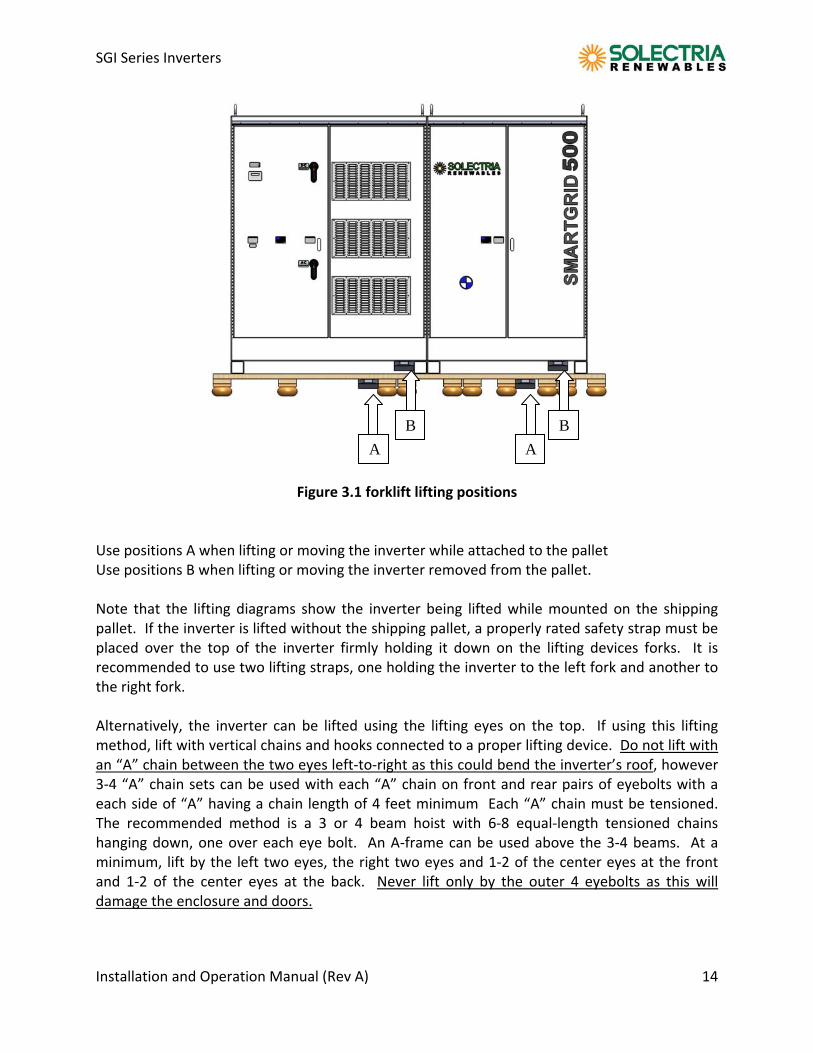
Figure 3.1 forklift lifting positions
Use positions A when lifting or moving the inverter while attached to the pallet Use positions B when lifting or moving the inverter removed from the pallet. Note that the lifting diagrams show the inverter being lifted while mounted on the shipping pallet. If the inverter is lifted without the shipping pallet, a properly rated safety strap must be placed over the top of the inverter firmly holding it down on the lifting devices forks. It is recommended to use two lifting straps, one holding the inverter to the left fork and another to the right fork. Alternatively, the inverter can be lifted using the lifting eyes on the top. If using this lifting method, lift with vertical chains and hooks connected to a proper lifting device. Do not lift with an “A” chain between the two eyes left‐to‐right as this could bend the inverter’s roof, however 3‐4 “A” chain sets can be used with each “A” chain on front and rear pairs of eyebolts with a each side of “A” having a chain length of 4 feet minimum Each “A” chain must be tensioned. The recommended method is a 3 or 4 beam hoist with 6‐8 equal‐length tensioned chains hanging down, one over each eye bolt. An A‐frame can be used above the 3‐4 beams. At a minimum, lift by the left two eyes, the right two eyes and 1‐2 of the center eyes at the front and 1‐2 of the center eyes at the back. Never lift only by the outer 4 eyebolts as this will damage the enclosure and doors.
B B
A A
SGI Series Inverters
Installation and Operation Manual (Rev A) 15
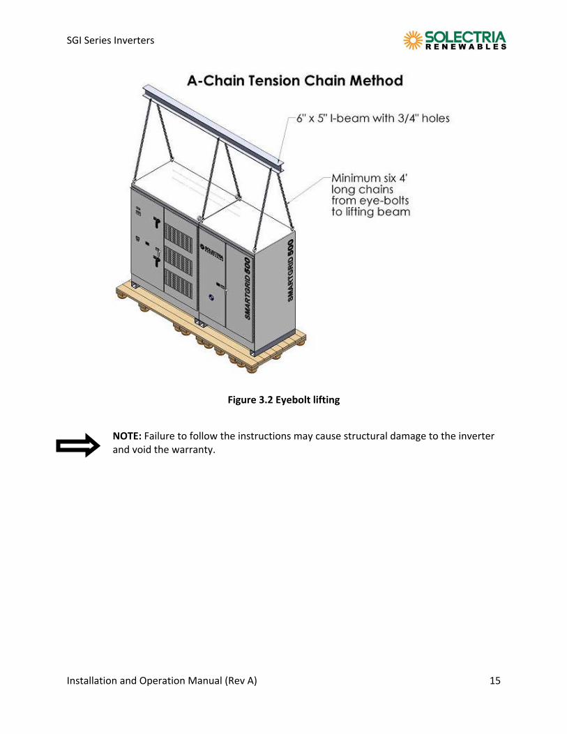
Figure 3.2 Eyebolt lifting
NOTE: Failure to follow the instructions may cause structural damage to the inverter and void the warranty.
SGI Series Inverters
Installation and Operation Manual (Rev A) 16
4.0 DC Electrical Connections and Connection to the Electrical Utility Grid
WARNING: All electrical installations shall be performed in accordance with all local electrical codes and the National Electrical Code, Canadian Electrical Code for Canada and ANSI/NFPA 70. Only make AC connections directly to the AC breaker and DC connections to the DC sub combiner panel.
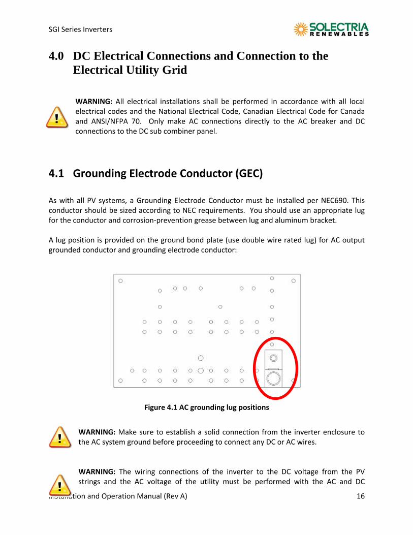
4.1 Grounding Electrode Conductor (GEC) As with all PV systems, a Grounding Electrode Conductor must be installed per NEC690. This conductor should be sized according to NEC requirements. You should use an appropriate lug for the conductor and corrosion‐prevention grease between lug and aluminum bracket. A lug position is provided on the ground bond plate (use double wire rated lug) for AC output grounded conductor and grounding electrode conductor:
Figure 4.1 AC grounding lug positions
WARNING: Make sure to establish a solid connection from the inverter enclosure to the AC system ground before proceeding to connect any DC or AC wires.
WARNING: The wiring connections of the inverter to the DC voltage from the PV strings and the AC voltage of the utility must be performed with the AC and DC
SGI Series Inverters
Installation and Operation Manual (Rev A) 17
disconnects off, building AC source circuit panel/breaker off and the PV module strings disconnected (or modules covered up).
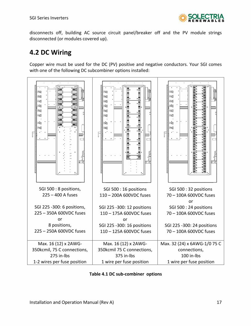
4.2 DC Wiring
Copper wire must be used for the DC (PV) positive and negative conductors. Your SGI comes with one of the following DC subcombiner options installed:
SGI 500 : 8 positions, 225 – 400 A fuses
SGI 225 ‐300: 6 positions, 225 – 350A 600VDC fuses
or 8 positions,
225 – 250A 600VDC fuses
SGI 500 : 16 positions
110 – 200A 600VDC fuses
SGI 225 ‐300: 12 positions 110 – 175A 600VDC fuses
or SGI 225 ‐300: 16 positions 110 – 125A 600VDC fuses
SGI 500 : 32 positions 70 – 100A 600VDC fuses
or SGI 500 : 24 positions
70 – 100A 600VDC fuses
SGI 225 ‐300: 24 positions 70 – 100A 600VDC fuses
Max. 16 (12) x 2AWG‐350kcmil, 75 C connections,
275 in‐lbs 1‐2 wires per fuse position
Max. 16 (12) x 2AWG‐350kcmil 75 C connections,
375 in‐lbs 1 wire per fuse position
Max. 32 (24) x 6AWG‐1/0 75 C connections, 100 in‐lbs
1 wire per fuse position
Table 4.1 DC sub‐combiner options
SGI Series Inverters
Installation and Operation Manual (Rev A) 18
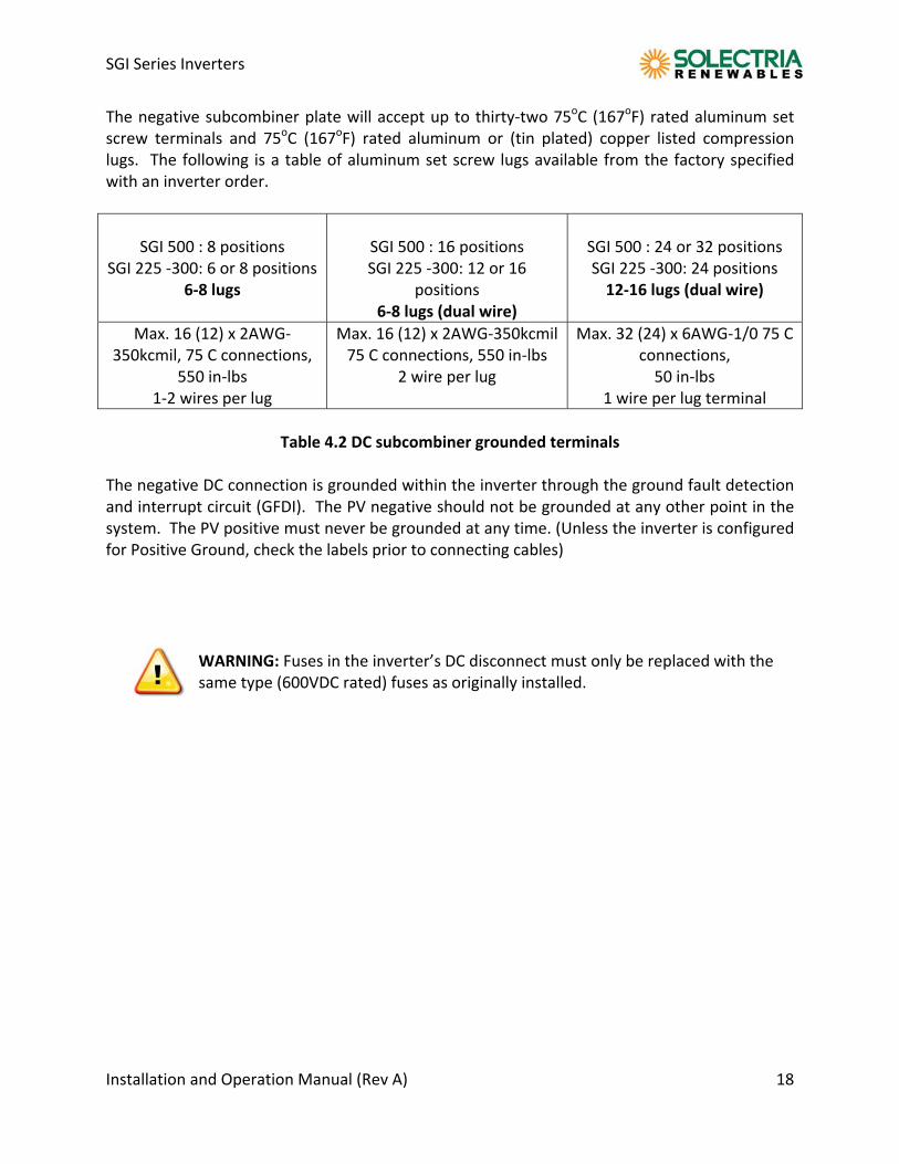
The negative subcombiner plate will accept up to thirty‐two 75oC (167oF) rated aluminum set screw terminals and 75oC (167oF) rated aluminum or (tin plated) copper listed compression lugs. The following is a table of aluminum set screw lugs available from the factory specified with an inverter order.
SGI 500 : 8 positions
SGI 225 ‐300: 6 or 8 positions 6‐8 lugs
SGI 500 : 16 positions SGI 225 ‐300: 12 or 16
positions 6‐8 lugs (dual wire)
SGI 500 : 24 or 32 positions SGI 225 ‐300: 24 positions 12‐16 lugs (dual wire)
Max. 16 (12) x 2AWG‐350kcmil, 75 C connections,
550 in‐lbs 1‐2 wires per lug
Max. 16 (12) x 2AWG‐350kcmil 75 C connections, 550 in‐lbs
2 wire per lug
Max. 32 (24) x 6AWG‐1/0 75 C connections, 50 in‐lbs
1 wire per lug terminal
Table 4.2 DC subcombiner grounded terminals
The negative DC connection is grounded within the inverter through the ground fault detection and interrupt circuit (GFDI). The PV negative should not be grounded at any other point in the system. The PV positive must never be grounded at any time. (Unless the inverter is configured for Positive Ground, check the labels prior to connecting cables)
WARNING: Fuses in the inverter’s DC disconnect must only be replaced with the same type (600VDC rated) fuses as originally installed.
SGI Series Inverters
Installation and Operation Manual (Rev A) 19
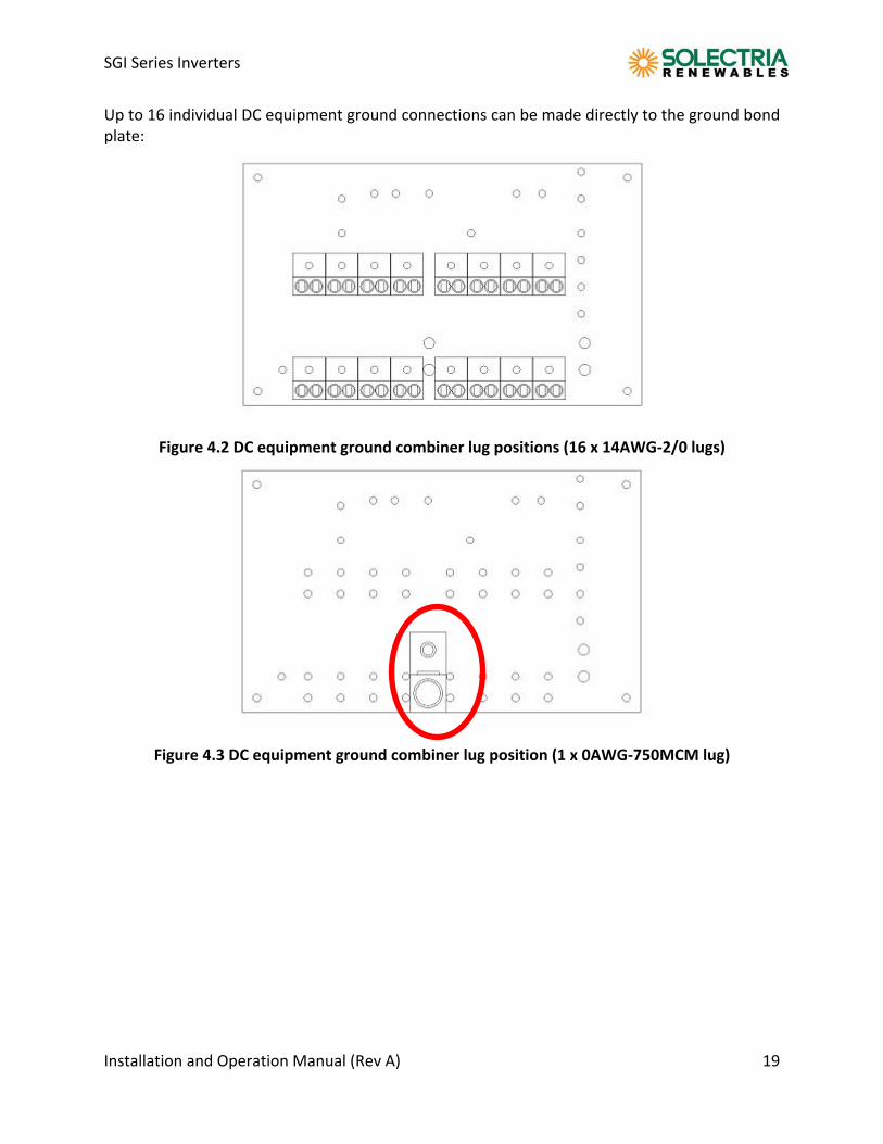
Up to 16 individual DC equipment ground connections can be made directly to the ground bond plate:
Figure 4.2 DC equipment ground combiner lug positions (16 x 14AWG‐2/0 lugs)
Figure 4.3 DC equipment ground combiner lug position (1 x 0AWG‐750MCM lug)
SGI Series Inverters
Installation and Operation Manual (Rev A) 20
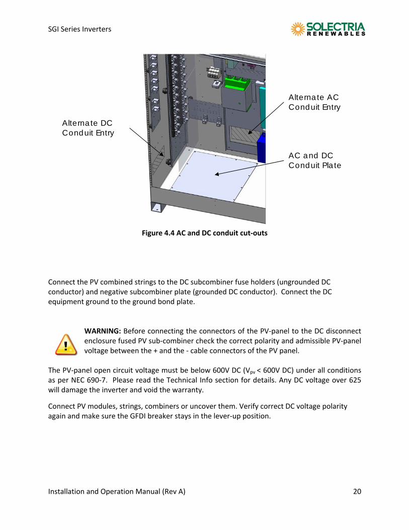
Figure 4.4 AC and DC conduit cut‐outs
Connect the PV combined strings to the DC subcombiner fuse holders (ungrounded DC conductor) and negative subcombiner plate (grounded DC conductor). Connect the DC equipment ground to the ground bond plate.
WARNING: Before connecting the connectors of the PV‐panel to the DC disconnect enclosure fused PV sub‐combiner check the correct polarity and admissible PV‐panel voltage between the + and the ‐ cable connectors of the PV panel.
The PV‐panel open circuit voltage must be below 600V DC (Vpv < 600V DC) under all conditions as per NEC 690‐7. Please read the Technical Info section for details. Any DC voltage over 625 will damage the inverter and void the warranty.
Connect PV modules, strings, combiners or uncover them. Verify correct DC voltage polarity again and make sure the GFDI breaker stays in the lever‐up position.
AC and DC Conduit Plate
Alternate AC Conduit Entry
Alternate DC Conduit Entry
SGI Series Inverters
Installation and Operation Manual (Rev A) 21
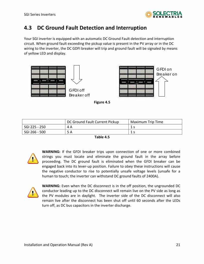
4.3 DC Ground Fault Detection and Interruption Your SGI inverter is equipped with an automatic DC Ground Fault detection and interruption circuit. When ground fault exceeding the pickup value is present in the PV array or in the DC wiring to the inverter, the DC GDFI breaker will trip and ground fault will be signaled by means of yellow LED and display.
Figure 4.5
DC Ground Fault Current Pickup Maximum Trip Time
SGI 225 ‐ 250 4 A 1 s
SGI 266 ‐ 500 5 A 1 s
Table 4.5
WARNING: If the GFDI breaker trips upon connection of one or more combined strings you must locate and eliminate the ground fault in the array before proceeding. The DC ground fault is eliminated when the GFDI breaker can be engaged back into its lever‐up position. Failure to obey these instructions will cause the negative conductor to rise to potentially unsafe voltage levels (unsafe for a human to touch; the inverter can withstand DC ground faults of 2400A).
WARNING: Even when the DC disconnect is in the off position, the ungrounded DC conductor leading up to the DC disconnect will remain live on the PV side as long as the PV modules are in daylight. The inverter side of the DC disconnect will also remain live after the disconnect has been shut off until 60 seconds after the LEDs turn off, as DC bus capacitors in the inverter discharge.
GFDI on Breaker on
GFDI off Breaker off
SGI Series Inverters
Installation and Operation Manual (Rev A) 22
4.4 AC Wiring
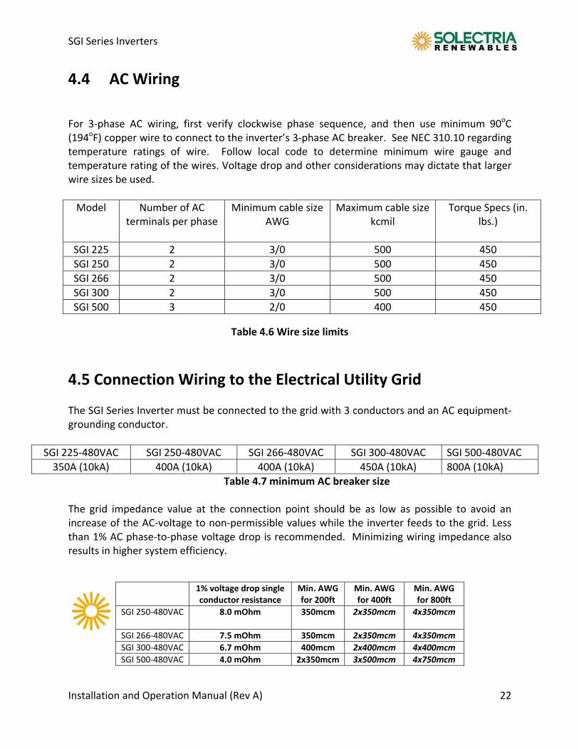
For 3‐phase AC wiring, first verify clockwise phase sequence, and then use minimum 90oC (194oF) copper wire to connect to the inverter’s 3‐phase AC breaker. See NEC 310.10 regarding temperature ratings of wire. Follow local code to determine minimum wire gauge and temperature rating of the wires. Voltage drop and other considerations may dictate that larger wire sizes be used.
Model Number of AC terminals per phase
Minimum cable size AWG
Maximum cable size kcmil
Torque Specs (in. lbs.)
SGI 225 2 3/0 500 450
SGI 250 2 3/0 500 450
SGI 266 2 3/0 500 450
SGI 300 2 3/0 500 450
SGI 500 3 2/0 400 450
Table 4.6 Wire size limits
4.5 Connection Wiring to the Electrical Utility Grid The SGI Series Inverter must be connected to the grid with 3 conductors and an AC equipment‐grounding conductor.
SGI 225‐480VAC SGI 250‐480VAC SGI 266‐480VAC SGI 300‐480VAC SGI 500‐480VAC
350A (10kA) 400A (10kA) 400A (10kA) 450A (10kA) 800A (10kA)
Table 4.7 minimum AC breaker size The grid impedance value at the connection point should be as low as possible to avoid an increase of the AC‐voltage to non‐permissible values while the inverter feeds to the grid. Less than 1% AC phase‐to‐phase voltage drop is recommended. Minimizing wiring impedance also results in higher system efficiency.
1% voltage drop single conductor resistance
Min. AWG for 200ft
Min. AWG for 400ft
Min. AWG for 800ft
SGI 250‐480VAC 8.0 mOhm 350mcm 2x350mcm 4x350mcm
SGI 266‐480VAC 7.5 mOhm 350mcm 2x350mcm 4x350mcm
SGI 300‐480VAC 6.7 mOhm 400mcm 2x400mcm 4x400mcm
SGI 500‐480VAC 4.0 mOhm 2x350mcm 3x500mcm 4x750mcm
SGI Series Inverters
Installation and Operation Manual (Rev A) 23
Example: Copper AWG needed to stay below recommended limit of 1% AC wire loss (400’ and over requires splicing 2 wires to maintain this low desired system resistance)
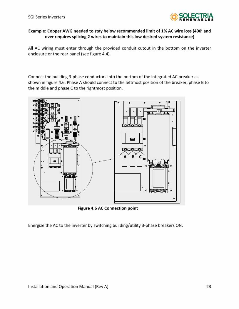
All AC wiring must enter through the provided conduit cutout in the bottom on the inverter enclosure or the rear panel (see figure 4.4).
Connect the building 3‐phase conductors into the bottom of the integrated AC breaker as shown in figure 4.6. Phase A should connect to the leftmost position of the breaker, phase B to the middle and phase C to the rightmost position. A B C Figure 4.6 AC Connection point Energize the AC to the inverter by switching building/utility 3‐phase breakers ON.
SGI Series Inverters
Installation and Operation Manual (Rev A) 24
4.6 AC Ground Fault Detection Your SGI inverter is not equipped with an AC Ground Fault detection circuit. Where required by local electrical code, the inverter AC output needs to be connected to the supply side of the installation’s AC ground fault protection.
4.7 Lightning and Surge Protection The SGI series is designed with certain protections against surges in voltage including certification to ANSI/IEEE 62.41/62.42 (as required in the NY SIR), however added protection and solid grounding provisions are important for best protection against utility surges and surges created by indirect lightning strikes. The installation of a UL listed lightning arrester of the correct specification is recommended on both the DC and AC inputs of inverter. This can be installed and wired using the manufacturer's directions. This device gives important added protection from indirect lightning strikes and resulting surges that provide protection beyond the inverter's IEEE 1547 requirements. It is suggested to drive a ground rod specifically for the PV array. It is also a very good idea to have the lightning protection system of the building checked and upgraded if needed before the PV system is installed. These added protections are especially important for area prone to thunder storms and possible nearby lightning strikes. Although these added precautions will not guarantee that there will be no damage from lightning, they can help prevent or limit potential damage.
SGI Series Inverters
Installation and Operation Manual (Rev A) 25
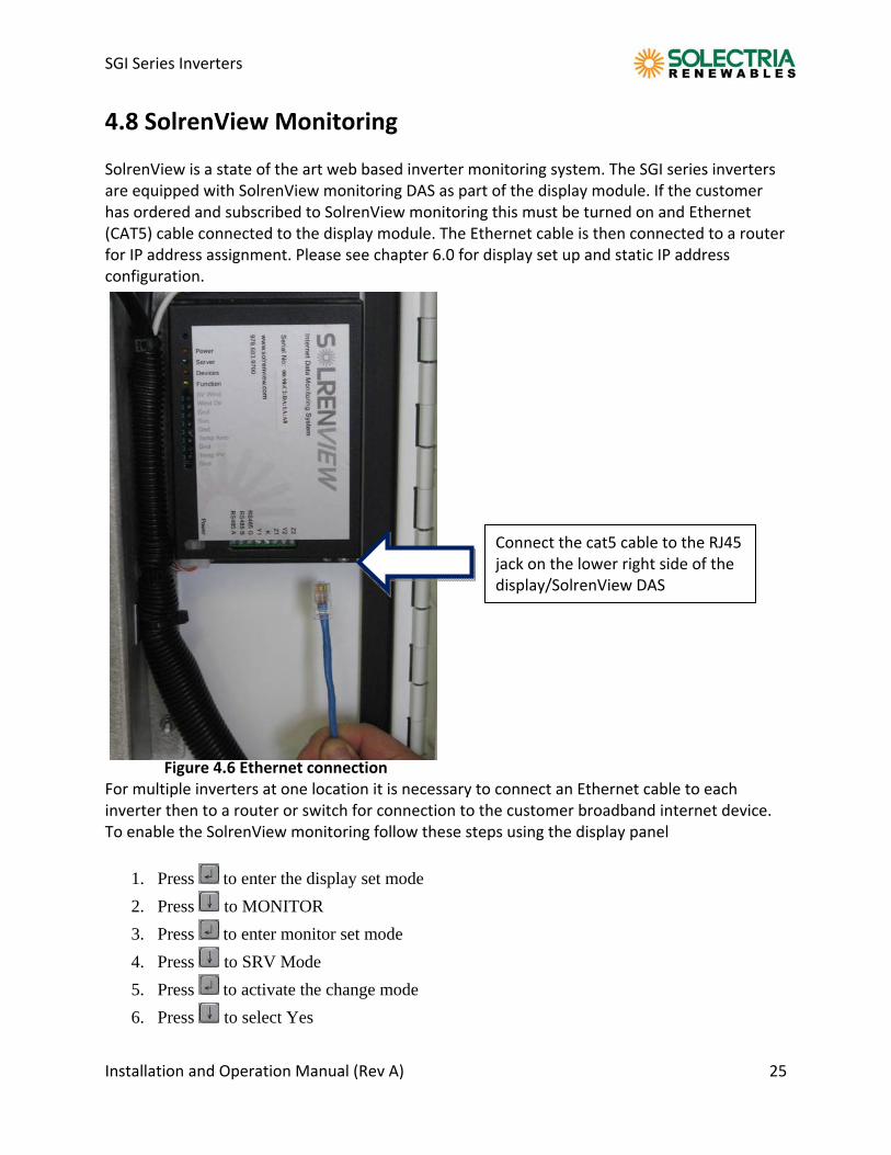
4.8 SolrenView Monitoring SolrenView is a state of the art web based inverter monitoring system. The SGI series inverters are equipped with SolrenView monitoring DAS as part of the display module. If the customer has ordered and subscribed to SolrenView monitoring this must be turned on and Ethernet (CAT5) cable connected to the display module. The Ethernet cable is then connected to a router for IP address assignment. Please see chapter 6.0 for display set up and static IP address configuration.
Figure 4.6 Ethernet connection For multiple inverters at one location it is necessary to connect an Ethernet cable to each inverter then to a router or switch for connection to the customer broadband internet device. To enable the SolrenView monitoring follow these steps using the display panel
1. Press to enter the display set mode
2. Press to MONITOR
3. Press to enter monitor set mode
4. Press to SRV Mode
5. Press to activate the change mode
6. Press to select Yes
Connect the cat5 cable to the RJ45 jack on the lower right side of the display/SolrenView DAS
SGI Series Inverters
Installation and Operation Manual (Rev A) 26
7. Press to confirm
5.0 Commissioning the Inverter PV System The inverter is mounted, all connections are made and you are ready to power it up.
NOTE: Make sure all tools, parts, etc. are removed from the vicinity of the inverter before turning on. WARNING: Make a final check of all AC and DC wiring to the inverter and in the system.
NOTE: With the PV modules connected and inverter disconnects still off, it is a good final precaution to check PV voltage and polarity once more using a digital volt meter and probing the positive (+) and negative (‐) PV connections. Verify clockwise AC phase rotation for L1, L2, L3 using a phase rotation meter.
5.1 Turning on the inverter:
Turn on the dedicated 3‐phase circuit breaker on the building electrical panel.
Turn on the Inverter’s 3‐phase AC disconnect.
Turn on the Inverter’s DC disconnect.
Watch the LED indicators for initialization (green and red LEDs on), then slow blinking green LED followed by faster blinking green LED. Watch the LCD display for prompts and system status.
Listen for contactor closing (inverter on‐line).
Listen for slight 60 Hz hum (transformer on‐line).
Following the blinking green LED and high frequency switching sound you should see a solid green LED. This confirms that the inverter is operating normally. The LCD display will show the AC Power (PAC), Energy (EAC), current and voltage as well as DC voltage.
5.2 Operation:
The control electronics will be active as soon as DC (PV) voltage reaches 300V DC. The inverter will go on‐line with the utility/building 3‐phase grid when the DC voltage first exceeds 370V DC (strike voltage). Next, the inverter will load the array, bringing the DC voltage down from 370V DC to not less than 300V DC.
Once there is enough PV power at 300V DC to back feed 3‐phase AC power switching will automatically feed power to the grid.
SGI Series Inverters
Installation and Operation Manual (Rev A) 27
Operating states, GFDI status and error indications shown by the LED indicators, which are described in chapter 6, “Power, GFDI and Error LED Indicators”.
6.0 LCD Display and LED Indicators
The inverter operates automatically without the need for user interaction or maintenance.
The Inverter automatically starts back feeding 3‐phase AC power into the grid when there is sufficient DC voltage and PV power is available. The inverter runs through various checks before connecting to the grid. This will be displayed on the LED’s and the LCD display during start up.
6.1 LCD Display
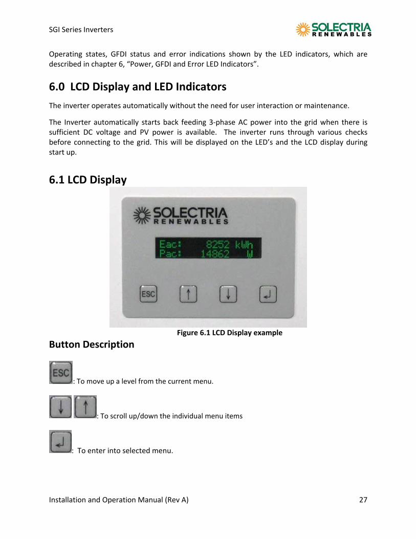
Figure 6.1 LCD Display example
Button Description
: To move up a level from the current menu.
: To scroll up/down the individual menu items
: To enter into selected menu.
SGI Series Inverters
Installation and Operation Manual (Rev A) 28
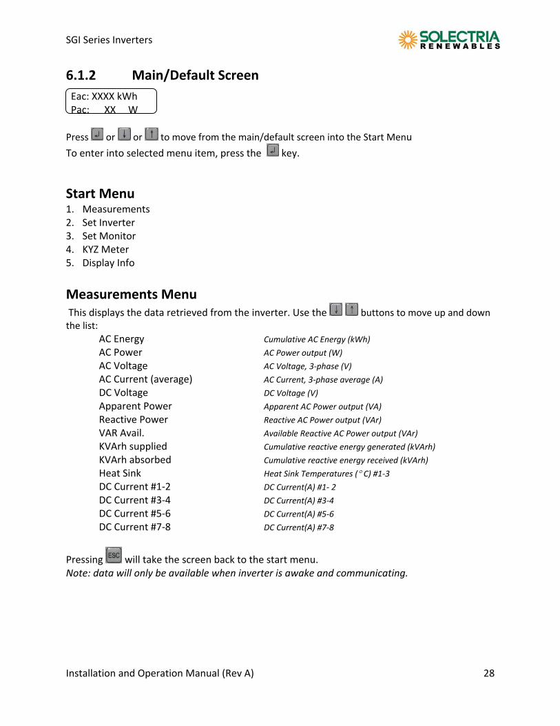
6.1.2 Main/Default Screen
Eac: XXXX kWh Pac: XX W
Press or or to move from the main/default screen into the Start Menu
To enter into selected menu item, press the key.
Start Menu 1. Measurements 2. Set Inverter 3. Set Monitor 4. KYZ Meter 5. Display Info
Measurements Menu This displays the data retrieved from the inverter. Use the buttons to move up and down the list: AC Energy Cumulative AC Energy (kWh) AC Power AC Power output (W) AC Voltage AC Voltage, 3‐phase (V) AC Current (average) AC Current, 3‐phase average (A) DC Voltage DC Voltage (V) Apparent Power Apparent AC Power output (VA) Reactive Power Reactive AC Power output (VAr) VAR Avail. Available Reactive AC Power output (VAr) KVArh supplied Cumulative reactive energy generated (kVArh) KVArh absorbed Cumulative reactive energy received (kVArh) Heat Sink Heat Sink Temperatures ( C) #1‐3 DC Current #1‐2 DC Current(A) #1‐ 2 DC Current #3‐4 DC Current(A) #3‐4 DC Current #5‐6 DC Current(A) #5‐6 DC Current #7‐8 DC Current(A) #7‐8
Pressing will take the screen back to the start menu. Note: data will only be available when inverter is awake and communicating.
SGI Series Inverters
Installation and Operation Manual (Rev A) 29
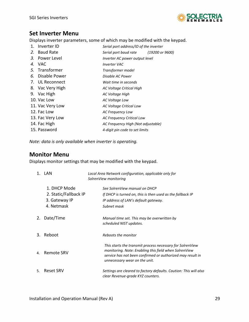
Set Inverter Menu Displays inverter parameters, some of which may be modified with the keypad. 1. Inverter ID Serial port address/ID of the inverter 2. Baud Rate Serial port baud rate (19200 or 9600) 3. Power Level Inverter AC power output level 4. VAC Inverter VAC 5. Transformer Transformer model 6. Disable Power Disable AC Power 7. UL Reconnect Wait time in seconds 8. Vac Very High AC Voltage Critical High 9. Vac High AC Voltage High 10. Vac Low AC Voltage Low 11. Vac Very Low AC Voltage Critical Low 12. Fac Low AC Frequency Low 13. Fac Very Low AC Frequency Critical Low 14. Fac High AC Frequency High (Not adjustable) 15. Password 4‐digit pin code to set limits Note: data is only available when inverter is operating.
Monitor Menu Displays monitor settings that may be modified with the keypad.
1. LAN Local Area Network configuration, applicable only for
SolrenView monitoring
1. DHCP Mode See SolrenView manual on DHCP 2. Static/Fallback IP If DHCP is turned on, this is then used as the fallback IP
3. Gateway IP IP address of LAN’s default gateway.
4. Netmask Subnet mask 2. Date/Time Manual time set. This may be overwritten by
scheduled NIST updates. 3. Reboot Reboots the monitor
4. Remote SRV
5. Reset SRV Settings are cleared to factory defaults. Caution: This will also
clear Revenue‐grade KYZ counters.
This starts the transmit process necessary for SolrenView monitoring. Note: Enabling this field when SolrenView service has not been confirmed or authorized may result in unnecessary wear on the unit.
SGI Series Inverters
Installation and Operation Manual (Rev A) 30
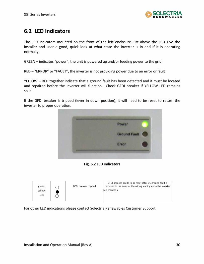
6.2 LED Indicators The LED indicators mounted on the front of the left enclosure just above the LCD give the installer and user a good, quick look at what state the inverter is in and if it is operating normally. GREEN – indicates “power”, the unit is powered up and/or feeding power to the grid RED – “ERROR” or “FAULT”, the inverter is not providing power due to an error or fault YELLOW – RED together indicate that a ground fault has been detected and it must be located and repaired before the inverter will function. Check GFDI breaker if YELLOW LED remains solid. If the GFDI breaker is tripped (lever in down position), it will need to be reset to return the inverter to proper operation.
Fig. 6.2 LED indicators
green:
GFDI breaker tripped GFDI breaker needs to be reset after DC ground fault is
removed in the array or the wiring leading up to the inverter
yellow: see chapter 5
red:
For other LED indications please contact Solectria Renewables Customer Support.
SGI Series Inverters
Installation and Operation Manual (Rev A) 31
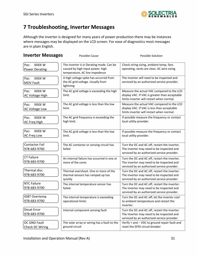
7 Troubleshooting, Inverter Messages
Although the inverter is designed for many years of power production there may be instances where messages may be displayed on the LCD screen. For ease of diagnostics most messages are in plain English.
Inverter Messages Possible Cause Possible Solution Pac: XXXX W Power Derating Pac: XXXX W MOV Fault
Pac: XXXX W AC Voltage High
Pac: XXXX W AC Voltage Low Pac: XXXX W AC Freq High Pac: XXXX W AC Freq Low
Contactor Fail 978‐683‐9700
CT Failure 978‐683‐9700 Thermal disc. 978‐683‐9700 NTC Failure 978‐683‐9700 IGBT Overtemp 978‐683‐9700 Desat Error 978‐683‐9700 DC GND Fault Check DC Wiring
The inverter is in Derating mode. Can be caused by high input power, high temperature, AC line impedence
Check string sizing, ambient temp, fans operating, vents are clear, AC wire sizing
A high voltage spike has occurred fromthe AC grid voltage. Usually from lightning
The inverter will need to be inspected and serviced by an authorized service provider.
The AC grid voltage is exceeding the high limit.
Measure the actual VAC compared to the LCD display VAC. If VAC is greater than acceptable limits inverter will restart when normal.
The AC grid voltage is less than the low limit.
Measure the actual VAC compared to the LCD display VAC. If VAC is less than acceptable limits inverter will restart when normal.
The AC grid frequency is exceeding the high limit.
If possible measure the frequency or contact local utility provider.
The AC grid voltage is less than the low limit.
If possible measure the frequency or contact local utility provider.
The AC contactor or sensing circuit has failed
Turn the DC and AC off, restart the inverter. The inverter may need to be inspected and serviced by an authorized service provider.
An internal failure has occurred in one or more of the cores
Turn the DC and AC off, restart the inverter. The inverter may need to be inspected and serviced by an authorized service provider.
Thermal overshoot. One or more of the thermal sensors has ramped up too quickly
Turn the DC and AC off, restart the inverter. The inverter may need to be inspected and serviced by an authorized service provider.
The internal temperature sensor has failed.
Turn the DC and AC off, restart the inverter. The inverter may need to be inspected and serviced by an authorized service provider.
The internal temperature is exceeding operational limits
Turn the DC and AC off, let the inverter cool to ambient temperature and restart the inverter.
Internal component sensing fault Turn the DC and AC off, restart the inverter. The inverter may need to be inspected and serviced by an authorized service provider.
The solar array or wiring has a fault to the ground circuit
Verify + and – VDC to ground repair fault and reset the GFDI circuit breaker
SGI Series Inverters
Installation and Operation Manual (Rev A) 32
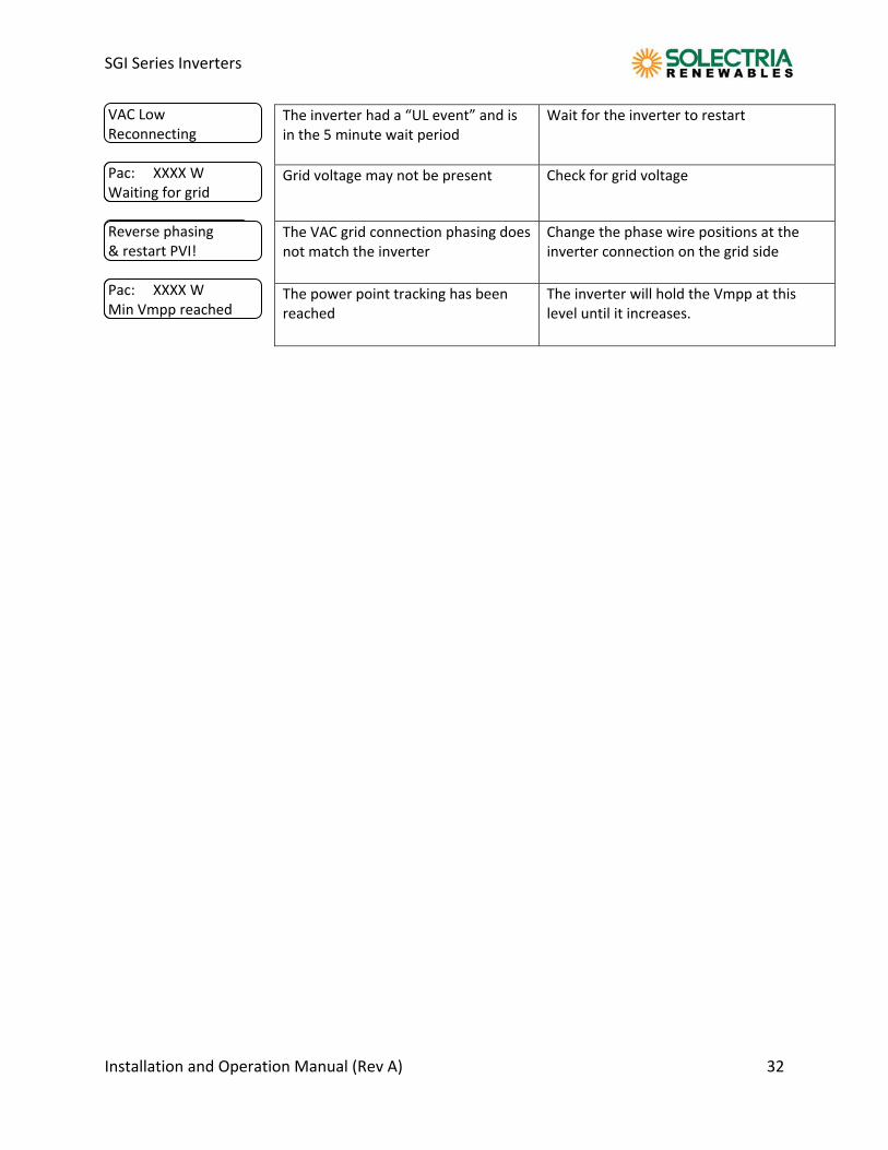
VAC Low Reconnecting Pac: XXXX W Waiting for grid Reverse phasing & restart PVI! Pac: XXXX W Min Vmpp reached
The inverter had a “UL event” and is in the 5 minute wait period
Wait for the inverter to restart
Grid voltage may not be present Check for grid voltage
The VAC grid connection phasing does not match the inverter
Change the phase wire positions at the inverter connection on the grid side
The power point tracking has been reached
The inverter will hold the Vmpp at this level until it increases.
SGI Series Inverters
Installation and Operation Manual (Rev A) 33
8 Product Warranty & RMA Policy
8.1 Warranty Policy The Solectria Renewables Warranty Policy is stated below.
Solectria Renewables Warranty Coverage: Solectria Renewables Limited Warranties are provided by Solectria Renewables, LLC. ("Solectria Renewables") and cover defects in workmanship and materials.
Duration of a Solectria Renewables Warranty Period: The warranty period is 60 months from the date of purchase of the SGI 225 / SGI 250/ SGI 266 / SGI 300 / SGI 500 by the end user or 64 months after the delivery date from Solectria Renewables to distributor or dealer/installer, whichever is shorter. If a warranty extension has been purchased, the term is defined as extension beyond 60 months. For example, if a 5‐year extension (to 10 years total) is purchased, the term becomes 120 months from date of purchase.
If Solectria Renewables repairs or replaces a product, its warranty continues for the remaining portion of the original Warranty Period or 90 days from the date of the repair to the product, whichever is greater.
All warranties are null and void if full payment for products and associated shipping are not received in full and in a timely manner by Solectria Renewables.
Please contact Solectria Renewables Customer Service for further details on other products.
Warranty service provided by Solectria Renewables: Solectria Renewables will, at its option, repair or replace the defective product free of charge, provided that you notify Solectria Renewables of the product defect within the Warranty Period for your product, and provided that Solectria Renewables, through inspection, establishes the existence of such a defect and that it is covered by the Limited Warranty.
Solectria Renewables will, at its option, use new and/or reconditioned parts in performing warranty repair and building replacement products. Solectria Renewables reserves the right to use parts or products of original or improved design in the repair or replacement. All replaced products and all parts removed from repaired products become the property of Solectria Renewables.
Solectria Renewables will attempt to repair the unit within a reasonable time period (there is no reimbursement for lost energy production.)
Solectria Renewables covers both parts and labor necessary to repair the product, and parts shipment to and from customer via a Solectria Renewables‐selected non‐expedited surface freight within the contiguous United States and Canada. For Alaska, Hawaii, Mexico and other countries shipping charges are one way to the customer location via non‐expedited freight. The

SGI Series Inverters
Installation and Operation Manual (Rev A) 34
customer, end user or installer is required to pay return shipping fees to Solectria Renewables. Contact Solectria Renewables customer service for details on freight policy for return shipments outside of the contiguous United States and Canada. Shipping fees do not include duties, taxes or other Governmental charges.
Obtaining Service: If your product requires troubleshooting or warranty service, contact your distributor or dealer/installer. If you are unable to contact your distributor or dealer/installer, or the distributor or dealer/installer is unable to provide service, contact Solectria Renewables directly at the number listed on the website in the customer service section for your product.
Solectria Renewables may send personnel to a jobsite or contract with an area technician, installer or other authorized, trained service personnel to service/replace components.
Reimbursement for contracted services: Solectria Renewables will submit a purchase order to the designated service personnel before work is performed. This purchase order will cover time expected for the required service and most likely an allocation for travel time.
Direct returns may be performed according to the Solectria Renewables Return Material Authorization Policy.
In any warranty claim, dated proof of purchase must accompany the product and the product must not have been disassembled or modified without prior written authorization by Solectria Renewables. Proof of purchase may be in any one of the following forms: ‐ The dated purchase receipt from the original purchase of the product at point of sale to the end user, or ‐ The dated distributor or dealer/installer invoice or purchase receipt showing original equipment manufacturer (OEM) status, or ‐ The dated invoice or purchase receipt showing the product exchanged under warranty.
Solectria Renewables normal office hours are Monday‐Friday, 8:30am‐5:30pm EST. After hours technical assistance is available. Once a problem is identified, necessary replacement component(s) will be dispatched within 48 hours to the jobsite or the designated service personnel's address or will be brought to the site by Solectria Renewables’ personnel.
What does the Solectria Renewables warranty not cover? Solectria Renewables Limited Warranties do not cover normal wear and tear of the product or costs related to the removal, installation, or troubleshooting of the customer's electrical systems. These warranties do not apply to and Solectria Renewables will not be responsible for any defect in or damage to: a) The product, if it has been misused, neglected, improperly installed, physically damaged or altered, either internally or externally, or damaged from improper use or use in an unsuitable environment;
SGI Series Inverters
Installation and Operation Manual (Rev A) 35
b) The product, if it has been subjected to fire, water, generalized corrosion, biological infestations, acts of God or input voltage that creates operating conditions beyond the maximum or minimum limits listed in the Solectria Renewables product specifications including high input voltage from generators and lightning strikes;
c) The product, if repairs have been done to it other than by Solectria Renewables or authorized, trained service personnel;
d) The product, if it is used as a component part of a product expressly warranted by another manufacturer;
e) The product, if its original identification (trademark, serial number) markings have been defaced, altered, or removed;
f) The product, if it has been damaged in shipping (unless approved in writing by Solectria Renewables);
g) Any installation and operation beyond the scope covered by relevant safety regulations (UL1741, NEC, Canadian standards, etc.);
h) Any third party accessories installed in or on the product. i) Loss of electricity generation, payment for utility bills, or any other costs related to the
inverter after installation. Extended warranties covering Solectria Renewables inverters do not cover external data monitoring hardware. DISCLAIMER SOLECTRIA RENEWABLES LIMITED WARRANTIES ARE THE SOLE AND EXCLUSIVE WARRANTY PROVIDED BY SOLECTRIA RENEWABLES IN CONNECTION WITH YOUR SOLECTRIA RENEWABLES PRODUCT AND ARE, WHERE PERMITTED BY LAW, IN LIEU OF ALL OTHER WARRANTIES, CONDITIONS, GUARANTEES, REPRESENTATIONS, OBLIGATIONS AND LIABILITIES, EXPRESS OR IMPLIED, STATUTORY OR OTHERWISE IN CONNECTION WITH THE PRODUCT, HOWEVER ARISING (WHETHER BY CONTRACT, TORT, NEGLIGENCE, PRINCIPLES OF MANUFACTURER'S LIABILITY, OPERATION OF LAW, CONDUCT, STATEMENT OR OTHERWISE), INCLUDING WITHOUT RESTRICTION ANY IMPLIED WARRANTY OR CONDITION OF QUALITY, DISTRIBUTOR OR DEALER/INSTALLER ABILITY OR FITNESS FOR A PARTICULAR PURPOSE. ANY IMPLIED WARRANTY OF DISTRIBUTOR OR DEALER/INSTALLER ABILITY OR FITNESS FOR A PARTICULAR PURPOSE TO THE EXTENT REQUIRED UNDER APPLICABLE LAW TO APPLY TO THE PRODUCT SHALL BE LIMITED IN DURATION TO THE PERIOD STIPULATED UNDER THIS LIMITED WARRANTY. IN NO EVENT WILL SOLECTRIA RENEWABLES, LLC, INCLUDING ITS SUPPLIERS, MANUFACTURERS, VENDORS, SUBCONTRACTORS, DISTRIBUTORS, DEALERS AND ANY OTHER AFFILIATES BE LIABLE FOR ANY SPECIAL, DIRECT, INDIRECT, INCIDENTAL OR CONSEQUENTIAL
SGI Series Inverters
Installation and Operation Manual (Rev A) 36
DAMAGES, LOSSES, COSTS OR EXPENSES HOWEVER ARISING WHETHER IN CONTRACT OR TORT INCLUDING WITHOUT RESTRICTION ANY ECONOMIC LOSSES OF ANY KIND, ANY LOSS OR DAMAGE TO PROPERTY, ANY PERSONAL INJURY, ANY DAMAGE OR INJURY ARISING FROM OR AS A RESULT OF ANY USE, MISUSE OR ABUSE, OR THE (IN‐) CORRECT INSTALLATION, INTEGRATION OR OPERATION OF THE PRODUCT. Solectria Renewables neither assumes nor authorizes any other person to assume for it any other liability in connection with the repair or replacement or the Product. Exclusions of the Policy: If your product is a consumer product, federal law does not allow an exclusion of implied warranties. To the extent you are entitled to implied warranties under federal law, to the extent permitted by applicable law they are limited to the duration of this Limited Warranty. Some states and provinces do not allow limitations or exclusions on implied warranties or on the duration of an implied warranty or on the limitation or exclusion of incidental or consequential damages, so the above limitation(s) or exclusion(s) may not apply to you. This Limited Warranty gives you specific legal rights. You may have other rights, which may vary from state to state or province to province. WITHOUT LIMITING THE GENERALITY OF THE FOREGOING, UNLESS SPECIFICALLY AGREED TO BY IT IN WRITING, SOLECTRIA RENEWABLES (a) MAKES NO WARRANTY AS TO THE ACCURACY, SUFFICIENCY OR SUITABILITY OF ANY TECHNICAL OR OTHER INFORMATION PROVIDED IN MANUALS OR OTHER DOCUMENTATION PROVIDED BY IT IN CONNECTION WITH THE PRODUCT; AND (b) ASSUMES NO RESPONSIBILITY OR LIABILITY FOR LOSSES, DAMAGES, COSTS OR EXPENSES, WHETHER SPECIAL, DIRECT, INDIRECT, CONSEQUENTIAL OR INCIDENTAL, WHICH MIGHT ARISE OUT OF THE USE OF SUCH INFORMATION. THE USE OF ANY SUCH INFORMATION WILL BE ENTIRELY AT THE USER'S RISK. WARNING: LIMITATIONS ON USE Please refer to your product user manual for limitations on uses of the product. Specifically, please note that Solectria Renewables products are not intended for use in connection with life support systems and Solectria Renewables makes no warranty or representation in connection with any use of the product for such purposes. Please review our Return Merchandise Authorization Policy for returning product to Solectria Renewables.
SGI Series Inverters
Installation and Operation Manual (Rev A) 37
8.2 Return Material Authorization Policy Obtaining a required, Return Material Authorization: Before returning a product directly to Solectria Renewables you must obtain a Return Material Authorization (RMA) number and the correct factory "Ship To" address. Products must also be shipped prepaid. Product shipments will be refused and returned at your expense if they are unauthorized, returned without an RMA number clearly marked on the outside of the shipping box, if they are shipped collect, or if they are shipped to the wrong location. Information Solectria Renewables needs when you are obtaining service: 1) The model names and serial number of your product 2) Information about the installation and use of the unit 3) Information about the failure and/or reason for the return 4) A copy of your dated proof of purchase. Preparing the product for shipping: 1) Package the unit or component safely, preferably using the original box and packing materials sent with the unit or component. Please ensure that your product is shipped fully insured in the original packaging or equivalent. This warranty will not apply where the product is damaged due to improper packaging. 2) Include the following: a. The RMA number supplied by Solectria Renewables, LLC clearly marked on the outside of the box b. A return address to which the unit can be shipped. Post office boxes are not acceptable. c. A contact telephone number where you can be reached during work hours. d. A brief description of the problem. Ship the unit prepaid to the address provided by your Solectria Renewables customer service representative. Returning a product from outside of the USA or Canada: In addition to the above, you MUST include return freight funds and are fully responsible for all documents, duties, tariffs, and deposits.
SGI Series Inverters
Installation and Operation Manual (Rev A) 38
9 Technical Data Technical Information and specifications – see appendix for complete SGI 225, SGI 250, SGI 266, SGI 300 and SGI 500 data sheet Input (DC) from PV array:
Maximum open circuit voltage of PV array: 600V DC
WARNING: NEC 690‐7 must be followed to calculate the maximum number of PV modules allowed for a maximum inverter open circuit voltage (OCV) of 600V DC in extreme cold temperatures for the installation location.
The open circuit voltage of PV modules depends on the cell temperature and the solar irradiation. The highest open circuit voltage occurs when the PV modules are at the coldest temperature and in bright sun.
Because the PV modules also have a reduction in voltage at high cell temperatures, you must make sure the MPP voltage of the strings will not drop below the minimum inverter DC input voltage of 300V DC in very hot temperature conditions. Both the maximum open circuit voltage (OCV) when at cold extreme and minimum MPP voltage when at hot extreme can be calculated for a PV module using its specification sheet. PV module string sizing can then be used to determine how many modules can/should be used in a string.
SGI Series Inverters
Installation and Operation Manual (Rev A) 39
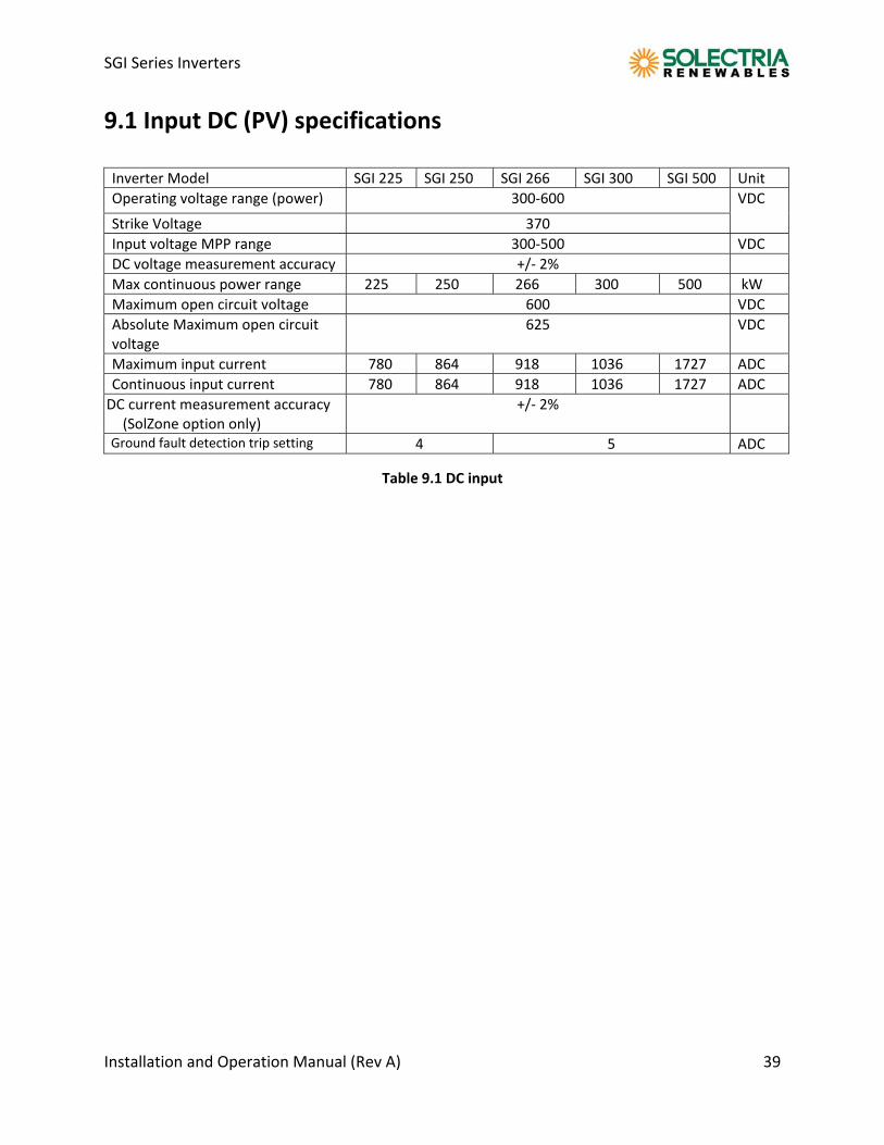
9.1 Input DC (PV) specifications Inverter Model SGI 225 SGI 250 SGI 266 SGI 300 SGI 500 Unit
Operating voltage range (power) 300‐600 VDC Strike Voltage 370
Input voltage MPP range 300‐500 VDC
DC voltage measurement accuracy +/‐ 2%
Max continuous power range 225 250 266 300 500 kW
Maximum open circuit voltage 600 VDC
Absolute Maximum open circuit voltage
625 VDC
Maximum input current 780 864 918 1036 1727 ADC
Continuous input current 780 864 918 1036 1727 ADC
DC current measurement accuracy (SolZone option only)
+/‐ 2%
Ground fault detection trip setting 4 5 ADC
Table 9.1 DC input
SGI Series Inverters
Installation and Operation Manual (Rev A) 40
9.2 Output to AC grid connection:
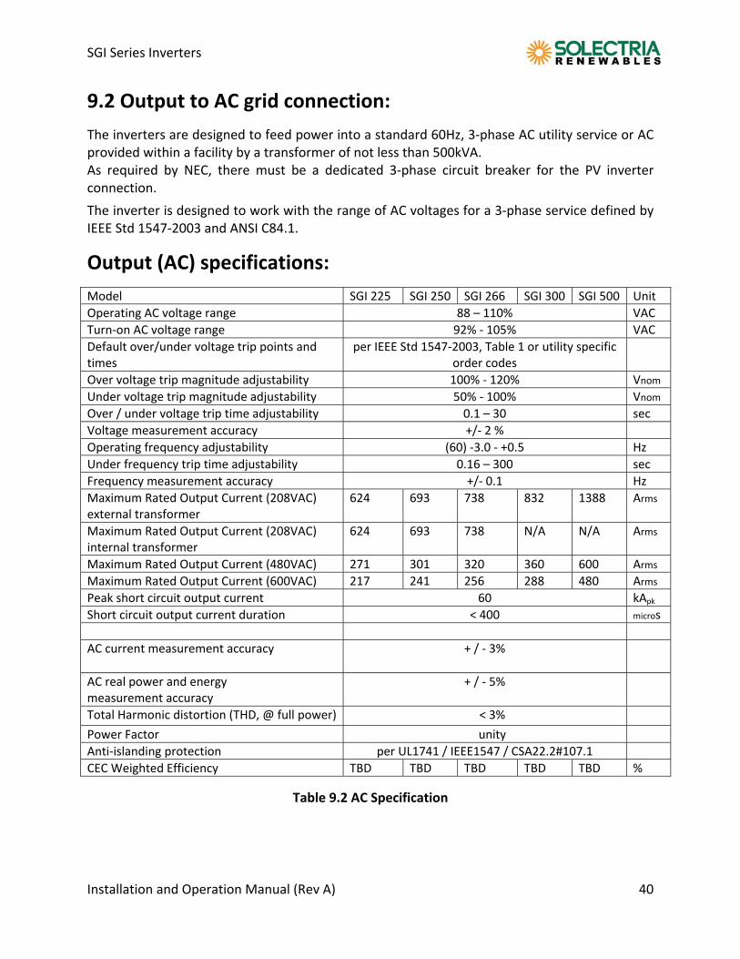
The inverters are designed to feed power into a standard 60Hz, 3‐phase AC utility service or AC provided within a facility by a transformer of not less than 500kVA. As required by NEC, there must be a dedicated 3‐phase circuit breaker for the PV inverter connection.
The inverter is designed to work with the range of AC voltages for a 3‐phase service defined by IEEE Std 1547‐2003 and ANSI C84.1.
Output (AC) specifications:
Model SGI 225 SGI 250 SGI 266 SGI 300 SGI 500 Unit
Operating AC voltage range 88 – 110% VAC
Turn‐on AC voltage range 92% ‐ 105% VAC
Default over/under voltage trip points and times
per IEEE Std 1547‐2003, Table 1 or utility specific order codes
Over voltage trip magnitude adjustability 100% ‐ 120% Vnom
Under voltage trip magnitude adjustability 50% ‐ 100% Vnom
Over / under voltage trip time adjustability 0.1 – 30 sec
Voltage measurement accuracy +/‐ 2 %
Operating frequency adjustability (60) ‐3.0 ‐ +0.5 Hz
Under frequency trip time adjustability 0.16 – 300 sec
Frequency measurement accuracy +/‐ 0.1 Hz
Maximum Rated Output Current (208VAC) external transformer
624 693 738 832 1388 Arms
Maximum Rated Output Current (208VAC) internal transformer
624 693 738 N/A N/A Arms
Maximum Rated Output Current (480VAC) 271 301 320 360 600 Arms
Maximum Rated Output Current (600VAC) 217 241 256 288 480 Arms
Peak short circuit output current 60 kApk
Short circuit output current duration < 400 micros
AC current measurement accuracy + / ‐ 3%
AC real power and energy measurement accuracy
+ / ‐ 5%
Total Harmonic distortion (THD, @ full power) < 3%
Power Factor unity
Anti‐islanding protection per UL1741 / IEEE1547 / CSA22.2#107.1
CEC Weighted Efficiency TBD TBD TBD TBD TBD %
Table 9.2 AC Specification
SGI Series Inverters
Installation and Operation Manual (Rev A) 41
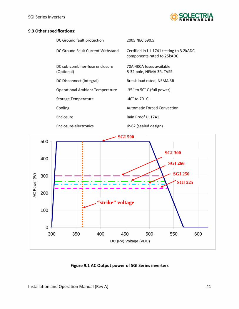
9.3 Other specifications:
DC Ground fault protection 2005 NEC 690.5 DC Ground Fault Current Withstand Certified in UL 1741 testing to 3.2kADC,
components rated to 25kADC DC sub‐combiner‐fuse enclosure 70A‐400A fuses available (Optional) 8‐32 pole, NEMA 3R, TVSS
DC Disconnect (Integral) Break load rated, NEMA 3R
Operational Ambient Temperature ‐35 o to 50o C (full power)
Storage Temperature ‐40o to 70o C
Cooling Automatic Forced Convection
Enclosure Rain Proof UL1741
Enclosure‐electronics IP‐62 (sealed design)
0
100
200
300
400
500
300 350 400 450 500 550 600
DC (PV) Voltage (VDC)
AC
Pow
er (
W)
Figure 9.1 AC Output power of SGI Series inverters
“strike” voltage
SGI 266
SGI 300
SGI 500
SGI 250
SGI 225
SGI Series Inverters
Installation and Operation Manual (Rev A) 42
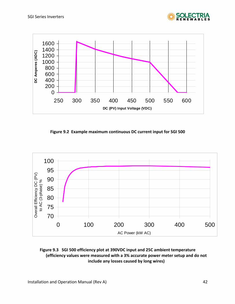
Figure 9.2 Example maximum continuous DC current input for SGI 500
Figure 9.3 SGI 500 efficiency plot at 390VDC input and 25C ambient temperature
(efficiency values were measured with a 3% accurate power meter setup and do not include any losses caused by long wires)
70
75
80
85
90
95
100
0 100 200 300 400 500AC Power (kW AC)
Ove
rall
Effi
cien
cy D
C (
PV
)to
AC
(3-
phas
e) %
0200400600800
1000120014001600
250 300 350 400 450 500 550 600DC (PV) Input Voltage (VDC)
DC
Am
pe
res
(A
DC
)
SGI Series Inverters
Installation and Operation Manual (Rev A) 43
10.0 Appendices Appendix A – SGI 250, SGI 266, SGI 300 and SGI 500 Data Sheet http://www.solren.com/downloads/SGI250 SGI266_SGI300_SGI500.pdf Appendix B – String sizing http://www.solren.com/stringSizing.html Appendix C ‐ Contact Information Solectria Renewables LLC 360 Merrimack Street Building 9, 2nd floor Lawrence, Massachusetts 01843 USA Tel: 978.683.9700 Fax: 978.683.9702 Sales/ general info: [email protected] Customer Support: [email protected] Website: www.solren.com Authorized Distributors/Dealers/Installers/Designers: See website for complete and updated listing: www.solren.com Specific Link: http://www.solren.com/contact/dist.htm
SGI Series Inverters
Installation and Operation Manual (Rev A) 44
Appendix D – UL1741 IEEE 1547 CSA22.2#107.1 Listing letter:
Recommended