119
SP-230—7
Innovative Triaxially Braided DuctileFRP Fabric for Strengthening Structures
by N.F. Grace, W.F. Ragheb, and G. Abdel-Sayed
Synopsis:Synopsis:Synopsis:Synopsis:Synopsis: This paper deals with the effectiveness of a new triaxially braided ductileFiber Reinforced Polymer (FRP) fabric for flexural strengthening of continuous reinforcedconcrete beams. The tested continuous beams had two spans strengthened in flexurealong their positive and negative moment regions and loaded with a concentrated loadat the middle of each span. One beam was not strengthened and was tested as acontrol beam. The behaviors of the beams strengthened with the new fabric wereinvestigated and compared with the behaviors of similar beams strengthened using acommercially available carbon fiber sheet. The responses of the beams were examinedin terms of deflections, strains, and failure modes. The beams strengthened with thenew fabric showed greater ductility than those strengthened with the carbon fibersheet. The new fabric provided reasonable ductility due to the formation of plastichinges that allowed for the redistribution of moment between the positive and negativemoment zones of the strengthened continuous beam. Redistribution of the momentenabled the full utilization of the strength of the beam at cross sections of maximumpositive and negative bending moments.
Keywords: braiding; concrete; ductility; fabric; flexural strengthening;FRP
120 Grace et al.Nabil F. Grace is a Professor and Chairman, Department of Civil Engineering, Lawrence
Technological University, Southfield, MI, USA.
Wael F. Ragheb is an Assistant Professor, Civil Engineering Department, Alexandria
University, Alexandria, Egypt. He obtained his Ph.D. from the Department of Civil and
Environmental Engineering, University of Windsor, Windsor, Ontario, Canada.
George Abdel-Sayed is a Professor Emeritus, Department of Civil and Environmental
Engineering, University of Windsor, Windsor, Ontario, Canada.
INTRODUCTION
Ductility is an important requirement in the design of any structural element. With
respect to reinforced concrete continuous beams, ductility allows the redistribution of
moment between the negative and positive moment zones. The formation of plastic
hinges allows the utilization of the full capacity of more cross sections of the beams.
However, the beam must be able to rotate adequately at the plastic hinges in order to
allow the redistribution of moment.
Fiber Reinforced Polymer (FRP) materials in forms such as pultruded plates, fabrics,
and sheets have been attractive for use as strengthening materials for reinforced concrete
beams. However, a large loss in beam ductility occurs when they are used for flexural
strengthening of reinforced concrete beams (Saadatmanesh and Ehsani 1991; Ritchie et
al. 1991; Triantafillou and Plevris 1992; Norris et al. 1997; Arduini et al. 1997;
Bencardino et al. 2002). The loss in beam ductility is attributed, in part, to the mechanical
characteristics of these materials. Because these materials have dissimilar behavior to that
of steel, i.e. they exhibit a linear stress-strain behavior up to failure (Grace et al. 2003);
they indirectly invoke brittle failures such as FRP debonding or shear-tension failure. In
addition, the gain in beam yield load and stiffness after strengthening is not as significant
as that of the ultimate load. Due to their high ultimate strains compared to the yield strain
of steel, the FRP do not contribute with significant amounts of their strength at low strain
levels such as that below the yield strain of steel.
Limited experimental investigations have been reported on the behavior of reinforced
concrete beams strengthened in flexure in their negative moment regions using FRP
materials. Grace et al. (1999) reported experimental investigations for reinforced concrete
beams strengthened in flexure using CFRP laminates. Although increase in ultimate load
was gained, large losses in ductility were experienced. The strengthened beams also
showed no yield plateaus. CFRP strips have been used to strengthen the negative moment
regions of reinforced concrete cantilever beams (Grace 2001). The strengthened beams
experienced brittle failures as a result of strip debonding or shear-tension failure at the
strip ends.
A new pseudo-ductile FRP strengthening fabric has been developed at the Structural
Testing Center at Lawrence Technological University. The fabric is unique in that it
exhibits a yield plateau similar to that exhibited by steel in tension. The fabric has a low
FRPRCS-7 121yield-equivalent strain (0.35%) [the first point on the load-strain curve where the
behavior becomes non-linear] that allows it to have the potential to contribute
significantly to the beam load before yielding of the steel reinforcement of the
strengthened beams, and a reasonable ultimate strain (around 2%), that allows the
strengthened beam to exhibit adequate ductility before the fabric ruptures. This fabric
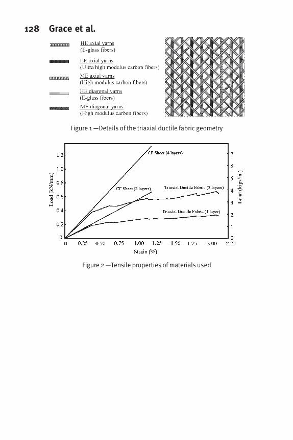
was manufactured by triaxially braiding bundles of carbon and glass fibers in three
different directions (+45o
, 0o
, -45o
). These fibers were selected with different ultimate
strains (0.35%, 0.8%, 2.10%) and were mixed in a way allowing them to fail successively
generating a yield plateau. The fabric was designed to be used for beam strengthening for
flexure and/or shear. The 0o
fibers are mainly used for flexural strengthening, while the
(+45o
, -45o
) fibers are mainly used for shear strengthening and to provide self anchoring
when wrapping the beam. Fig. 1 shows details of the triaxial ductile fabric geometry and
Fig. 2 shows the average tensile load-strain response of samples tested in the 0o
direction,
according to ASTM D 3039 specifications. Grace et al. (2003) used this fabric to
strengthen reinforced concrete simple beams for flexure. The beams strengthened with
the new fabric behaved in a more ductile manner than those strengthened with the carbon
fiber sheets. The beams strengthened with the new fabric produced yield plateaus similar
to that of the unstrengthened beam and also similar to those produced by beams
strengthened with steel plates. In this paper, the effectiveness of this fabric in providing
ductile behavior in reinforced concrete continuous beams strengthened in flexure is
investigated.
RESEARCH SIGNIFICANCE
Ductility is a very important requirement in the design of structural elements. Ductile
structures can exhibit large deformations before any potential failure and thus provide
visual indicators that give the opportunity for remedial actions prior to failure. Ductility is
even more important for statically indeterminate structures, such as continuous beams, as
it allows for moment redistribution through the rotations of plastic hinges. Moment
redistribution permits the utilization of the full capacity of more segments of the beam. A
large loss in ductility is experienced when using currently available FRP materials for
strengthening reinforced concrete beams for flexure. This paper investigates the
capability of a new triaxial ductile FRP fabric to offer adequate ductility at the plastic
hinge regions of strengthened reinforced concrete continuous beams in flexure.
EXPERIMENTAL PROGRAM
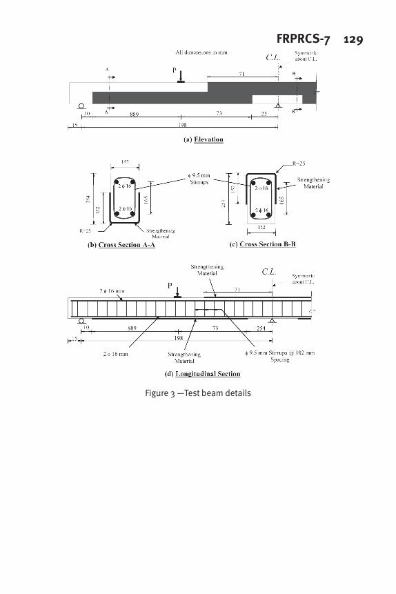
Test beams
The experimental program consisted of testing three continuous beams. All beams had
identical cross sectional dimensions of 152 mm 3 254 mm (6 in. 310 in.) and lengths of
4267 mm (168 in.). The beams were symmetrically reinforced with two #5 (φ16 mm)
rods at the top and the bottom. In order to avoid shear failure, the beams were over-
reinforced for shear with #3 (φ 9.5 mm) closed stirrups spaced at 102 mm (4 in.). The
beams were tested with two continuous spans. Fig. 3 shows the dimensions,
reinforcement details, and loading set up of the test beams, respectively. The beams were
prepared by sandblasting their surfaces to roughen them, cleaned with an air nozzle, and
122 Grace et al.finally wiped to remove any dust. The compressive strength of the concrete at the time
the beams were tested was 41.5 MPa (6,000 psi). The steel reinforcement used had a
yield stress of 490 MPa (71,000 psi).
Strengthening materials
In addition to the new triaxial ductile fabric, a commercially available carbon fiber
sheet was used to strengthen similar beams in order to compare their behavior with those
strengthened with the new fabric. In order to have an objective comparison, the carbon
fiber sheet was selected to have a similar load-strain response to that initially exhibited by
the triaxial ductile fabric (before exceeding its yield-equivalent point). The tested load-
strain diagrams of the triaxial ductile fabric and the carbon fibers sheet are shown in Fig.
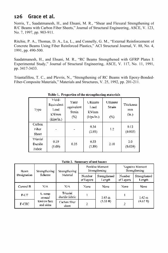
2 and their properties are listed in Table 1. Herein, it can be noted that the triaxial ductile
fabric has a yield-equivalent load of 0.19 KN/mm (1.08 kips/in.) and an initial modulus
of 50 GPa (7229 ksi), while the carbon fiber sheet has an ultimate load of 0.34 KN/mm
(1.95 kips/in). Using the tensile properties of the materials, it was determined that two
layers of the carbon fiber sheet would exhibit a load-strain response similar to that
initially exhibited by one layer of the triaxial ductile fabric. An epoxy resin was used to
impregnate the fibers and to act as an adhesive between the strengthening material and
the concrete surface. This epoxy has an ultimate tensile strength of 66.2 MPa (9.62 ksi)
with an ultimate strain of 4.4% and a compressive strength of 109.2 MPa (15.84 ksi).
Strengthening and set up
Test program consisted of three continuous beams. Each beam had two spans of 1981
mm (78 in.) each. The beams were loaded with a concentrated load at the middle of each
span. One of these beams had no external strengthening and was tested as a control beam.
The other two beams were strengthened along their negative and positive moment regions
around the top/bottom face extending 152 mm (6 in.) on both sides as a U-wrap at the
locations shown in Fig. 3. The first beam, beam F-CT, was strengthened using one layer
of the triaxial ductile fabric that was 457 mm (18 in.) wide, U-wrapped around the
tension faces and the sides, while the other beam, beam F-CTC, was strengthened using
two layers of the carbon fiber sheet that were each 457 mm (18 in.) wide, with the same
wrapping scheme. The deflection was measured at the middle and quarter sections of
each span using string potentiometers. The FRP strain was measured at the beam tension
face at the central support and at the middle of each span using electrical resistance strain
gages. The reaction of the beam at the central support was measured using a load cell.
Two hydraulic actuators were used to load the beam, one for each span. The load of each
actuator was measured using a load cell. Table 2 summarizes the test beams.
TEST RESULTS AND DISCUSSION
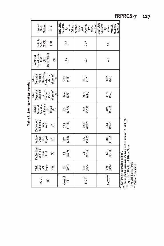
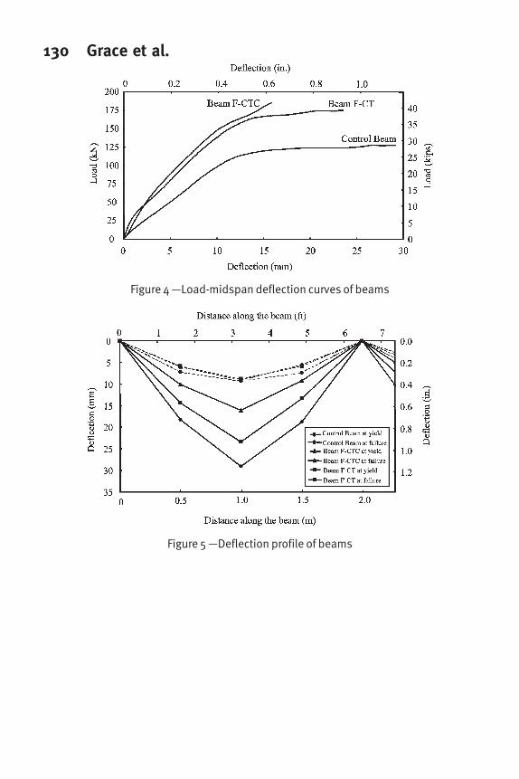
Test results for the beams are shown Fig. 4 through 7, and listed in Table 3. The failed
beams are shown in Fig. 8 through 11. Note that the load in Figures 4, 6, and 7 is the load
at each span (P) and not the total load on the beam. The beam ductility index is calculated
as the ratio between the ultimate midspan deflection and its deflection at first yield.
FRPRCS-7 123Control Beam B
The control beam exhibited a linear load-deflection behavior after cracking up to
yielding of the tension steel at the section of the maximum negative bending moment
over the central support, which occurred at a load of 92 kN (20.7 kips). After this point, a
gradual decrease in the slope of the load-deflection curve was observed. The tension steel
at the sections of the maximum positive bending moment yielded later, causing a
significant decrease in beam stiffness as the deflection then started to increase
significantly without a corresponding increase in load, as shown in Fig. 4. The beam
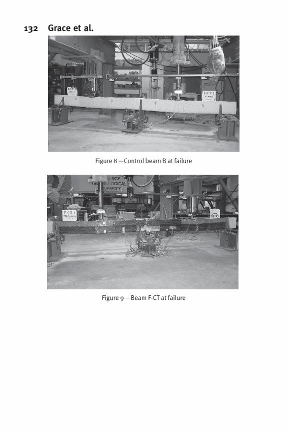
failed by compression failure of the concrete at the midspan at a load of 127 kN (28.5
kips). A ductility index of 3.12 was observed. The beam deflection profile, shown in Fig
5, indicates that deformation of the beam at failure was very localized at the sections of
maximum positive and negative moments, at the midspan and the central support,
respectively.
Beam F-CT
Beam F-CT yielded at a load of 126 kN (28.3 kips) due to yielding of both tension
steel and fabric over the central support. Yielding of the fabric was accompanied by the
sounds of rupture of the low elongation fibers of the fabric. A gradual decrease in beam
stiffness was observed, which was revealed by the decrease in the slope of the load-
deflection curve, as shown in Fig. 4. A significant decrease in beam stiffness was
observed after yielding of the beam at the sections of maximum positive moment, which
was caused by yielding of both the tension steel and the fabric. A yield plateau similar to
that exhibited by the control beam was exhibited thereafter until failure at a load of 175
kN (39.2 kips). The beam failed by tensile rupture of the fabric over the central support,
followed by rupture of the fabric at midspan (see Fig. 9). A ductility index of 2.57 was
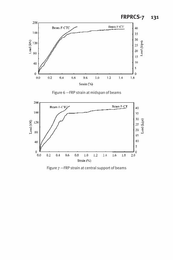
exhibited, which was 18% less than that of the control beam. The load-strain diagrams of
the fabric at the midspan and over the central support are shown in Fig. 6 and 7,
respectively. At first failure, the fabric exhibited strain values of 1.8% and 1.47% at the
sections of maximum negative and positive moments, respectively. The fact that these
strain values were more than the yield-equivalent strain of the fabric indicated that full
fabric strength was exploited.
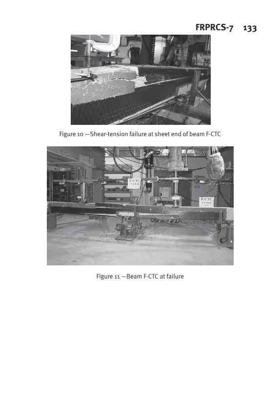
Beam F-CTC
Beam F-CTC yielded at a load of 136 kN (30.6 kips), where a slight decrease in the
load –deflection curve slope was exhibited caused by yielding of the tension steel at the
section of the maximum negative moment over the central support. The beam exceeded
the load achieved by beam F-CT and failed suddenly at a load of 185 kN (41.6 kips) by
shear-tension failure at one end of the negative moment strengthening carbon fiber sheet,
as shown in the photo in Fig. 10, followed by debonding of the carbon fiber sheet of the
positive moment, as shown in Fig. 11. A ductility index of 1.81 was observed, which was
42% less than that of the control beam. The load-deflection curve indicates a very brittle
response as shown in Fig. 4. No significant yield plateau was experienced. The load-
strain curves, shown in Fig. 6 and 7, indicate that the carbon fiber sheet exhibited
noticeably less strain than the triaxial ductile fabric used in beam F-CT. The maximum
recorded strain values did not exceed 0.66%, which indicated that nearly half the strength
of the carbon fiber sheet was not exploited.
124 Grace et al.The new triaxial ductile fabric contains bundles of fibers in the ± 45
o
directions. These
fibers enable the fabric to have a self-anchorage along its length, when U-wrapped
around the tension face and the vertical sides of the beam. As a result, anchorage failures
similar to those experienced by beam F-CTC were not experienced in case of beam F-CT.
On the other hand, the carbon fiber sheet used in beam F-CTC is uniaxial, and hence
wrapping the beam did not enhance the anchorage. In addition, yielding of the fabric
limited the increase in the tensile force developed in it. Therefore, the fabric needed less
anchorage than the carbon fiber sheet, whose tensile force kept increasing until a brittle
failure took place.
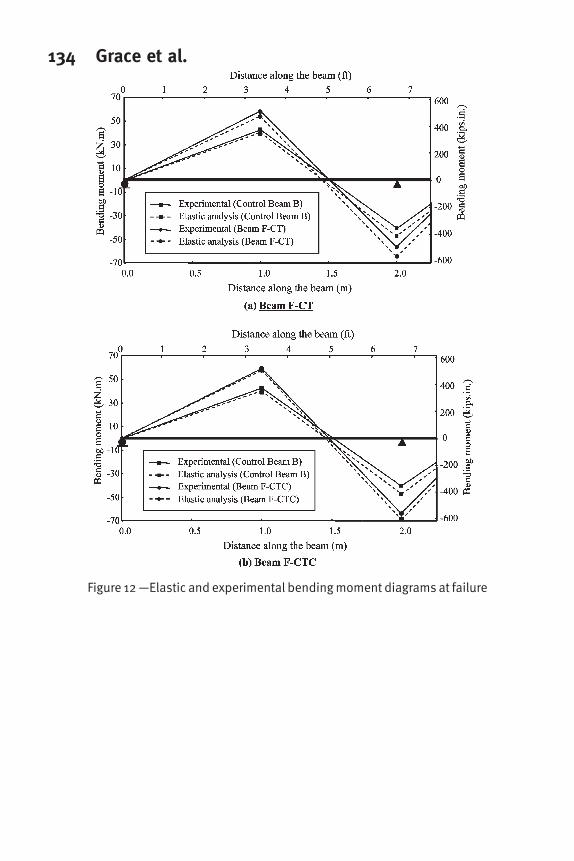
Using the readings of the load cell located at the central support, the actual bending
moment diagram for each beam at failure was determined. Also, the bending moment
diagram based on elastic analysis was determined for each beam using the value of the
failure load. This is shown in Fig. 12. It is clear from the figure that unlike beam F-CTC,
beam F-CT exhibited a similar level of moment redistribution to that of the control beam.
The moment redistribution ratio shown in Table 3 was calculated for each beam by
calculating the value of the maximum negative moment, based on the elastic analysis,
and comparing it with the experimental value at beam failure. Beam F-CT had a
redistribution ratio of 13.4%, which was 6% less than that of the control beam. On the
other hand, beam F-CTC had a redistribution ratio of 6.5%, which was significantly less
than that of beam F-CT. The ductile behavior of the new fabric resulted in a reasonable
ductility in the plastic hinge regions in beam F-CT, which in turn allowed for the
redistribution of moment between positive and negative moment zones.
CONCLUSIONS
The unique characteristics of the new triaxial ductile fabric helped to reduce the
significant loss in beam ductility associated with the use of conventional FRP materials in
flexural strengthening of reinforced concrete beams. The beams strengthened with the
new fabric exhibited higher ductility index than those strengthened with the carbon fiber
sheet.
The triaxial ductile fabric was successful in providing reasonable ductility at the
plastic hinge regions. Therefore, the redistribution of the moment between the negative
and positive moment zones of the continuous beam became possible. Redistribution of
the moment allowed full utilization of the strength of the beam at the cross sections of
maximum positive and negative moments.
Yielding of the triaxial ductile fabric was accompanied by various noticeably audible
sounds for a long period of time that are loud enough to be considered as a warning sign.
The beams strengthened with the triaxial ductile fabric did not exhibit anchorage
failures. That is attributed, in part, to its ductile behavior. The force in the fabric did not
significantly increase after it yielded. Thus, it did not exceed its anchorable force limit
and debonding did not take place.
FRPRCS-7 125The existence of bundles of fibers in the ± 45
o
directions enable the triaxial ductile
fabric to “self anchor” itself when wrapped around the tension face and the vertical sides
of the beam along its length. Therefore, it was generally less vulnerable to anchorage
failures than the uniaxial carbon fiber sheet.
The strength of the triaxial ductile fabric was fully exploited as its maximum recorded
strains before beam failure were much more than its yield-equivalent strain. In contrast,
the maximum recorded strains of the carbon fiber sheet were noticeably less than its
ultimate strain, which indicated that its strength was not fully exploited.
ACKNOWLEDGMENTS
This research has been conducted at the Structural Testing Center at Lawrence
Technological University, Southfield, Michigan, USA, and was funded by the National
Science Foundation under grant No. CMS-9906404, awarded to the first author. The
authors wish to thank Diversified Composites Inc., Erlanger, Kentucky for manufacturing
the fabric, Shelby Precast Concrete, Shelby Township, Michigan, for contributing the test
beams, and Baker Concrete Technology Inc., Columbus, Ohio, for contributing the
carbon fiber sheet used.
REFERENCES
Arduini, M., Tommaso, A. D., and Nanni, A., “Brittle Failure in FRP Plate and Sheet
Bonded Beams,” ACI Structural Journal, V. 94, No. 4, 1997, pp. 363-370.
ASTM D 3039, “Standard Test Method for Tensile Properties of Polymer Matrix
Composite Materials,” Annual Book of ASTM Standards, ASTM, V. 15.03, 2000, pp.
106-118.
Bencardino, F., Spadea, G., Swamy, N., “Strength and Ductility of Reinforced Concrete
Beams Externally Reinforced with Carbon Fiber Fabric,” ACI Structural Journal, V. 99,
No. 2, 2002, pp. 163-171.
Grace, N. F., Soliman, A. K., Abdel-Sayed, G., and Saleh, K. R., “Strengthening of
Continuous Beams Using Fiber Reinforced Polymer Laminates,” 4th
International
Symposium on Fiber Reinforced Polymer Reinforcement for Reinforced Concrete
Structures, SP-188, American Concrete Institute, 1999, pp. 647-657.
Grace, N. F., “Strengthening of Negative Moment Regions of Reinforced Concrete
Beams Using Carbon Fiber-Reinforced Polymer Strips,” ACI Structural Journal, V. 98,
No. 3, 2001, pp. 347-358.
Grace, N. F., Abdel-Sayed, G., and Ragheb, W. F., “Flexural and Shear Strengthening of
Concrete Beams Using New Triaxially Braided Ductile Fabric,” ACI Structural Journal,
V. 100, No. 6, November-December, 2003, pp. 804-814.
126 Grace et al.Norris, T., Saadatmanesh, H., and Ehsani, M. R., “Shear and Flexural Strengthening of
R/C Beams with Carbon Fiber Sheets,” Journal of Structural Engineering, ASCE, V. 123,
No. 7, 1997, pp. 903-911.
Ritchie, P. A., Thomas, D. A., Lu, L., and Connelly, G. M., “External Reinforcement of
Concrete Beams Using Fiber Reinforced Plastics,” ACI Structural Journal, V. 88, No. 4,
1991, pp. 490-500.
Saadatmanesh, H., and Ehsani, M. R., “RC Beams Strengthened with GFRP Plates I:
Experimental Study,” Journal of Structural Engineering, ASCE, V. 117, No. 11, 1991,
pp. 3417-3433.
Triantafillou, T. C., and Plevris, N., “Strengthening of RC Beams with Epoxy-Bonded-
Fiber-Composite Materials,” Materials and Structures, V. 25, 1992, pp. 201-211.
FRPRCS-7 127
128 Grace et al.
Figure 1 —Details of the triaxial ductile fabric geometry
Figure 2 —Tensile properties of materials used
FRPRCS-7 129
Figure 3 —Test beam details
130 Grace et al.
Figure 4 —Load-midspan deflection curves of beams
Figure 5 —Deflection profile of beams
FRPRCS-7 131
Figure 6 —FRP strain at midspan of beams
Figure 7 —FRP strain at central support of beams
132 Grace et al.
Figure 8 —Control beam B at failure
Figure 9 —Beam F-CT at failure
FRPRCS-7 133
Figure 10 —Shear-tension failure at sheet end of beam F-CTC
Figure 11 —Beam F-CTC at failure
134 Grace et al.
Figure 12 —Elastic and experimental bending moment diagrams at failure
Recommended