INMARSAT 4F2
ATTACHMENT 1
TECHNICAL DESCRIPTION
A.1 GENERAL DESCRIPTION
The Inmarsat 4F2 satellite, licensed in the United Kingdom, will provide Mobile-Satellite
Services to small User Terminals (“UTs”) in North America and other regions visible from the
satellite, using the 1525 - 1559 MHz band for space-to-Earth transmissions and the 1626.5-
1660.5 MHz band for Earth-to-space transmissions1. A new service to be launched on the
satellite is the Broadband Global Area Network (“BGAN”), which delivers simultaneous
broadband data and voice to a variety of small, lightweight UTs. The broadband service is IP
based, offering variable data rates up to 492 kbit/s, including fully symmetric services, and for
certain UTs, guaranteed bandwidth streaming services. The circuit-based services include
both voice and 64 kbit/s ISDN.
This request for authority to communicate with Inmarsat 4F2 should be treated as a request to
communicate with a replacement satellite for purposes of the Commission’s satellite
application processing procedures. Inmarsat 4F2, to be located at 52.75° W.L will replace the
existing Inmarsat 3 satellite at 54° W.L., will serve the same geographic regions as Inmarsat 3,
and will operate over the same L-band service link frequencies that are authorized for use on
Inmarsat 3 under existing Commission authority.2 For the reasons provided below, this
application therefore should be processed on a streamlined basis, and without a modified
processing round.
Because the L-band payload of Inmarsat 4F2 that is the subject of this application will provide
mobile satellite service (“MSS”), it is considered NGSO-like for Commission processing
purposes. The modified processing round procedure that generally applies to requests to
1 These bands are collectively known as the “L-band” frequencies.
2
communicate with NGSO-like satellite systems3 is inapplicable in situations such as this one,
where an NGSO-like satellite will use the same L-band service link frequencies already
authorized for use over an existing satellite in the operator’s network. Commission precedent
is clear that such requests are to be processed without instituting a modified processing round.4
In fact, Inmarsat 4F2 is appropriately considered a replacement for Inmarsat 3. As noted
above, the L-band frequency range on Inmarsat 4F2 is the same as the frequency range that the
Commission has authorized for communication with Inmarsat 3 at 54º W.L. and Inmarsat 4F2
will serve the same geographic area as Inmarsat 3. The Commission has indicated that
streamlined processing and “grant stamp” approvals are appropriate for replacement satellite
authority if the applicant is otherwise qualified.5 In its recent order granting MSV authority to
launch and operate an L-band MSS satellite at 101° W.L., the Commission confirmed that its
general policy about replacement expectancies are fully applicable in cases such as this that
involve a follow-on NGSO-like satellite.6
Furthermore, under Section 25.165(e) of the Commission’s rules, no bond need be posted with
respect to this application. As set forth above, Inmarsat 4F2 will operate on the same L-band
service link frequencies, and serve the same geographic area, as Inmarsat 3. Moreover,
Inmarsat anticipates retiring Inmarsat 3 from service at 54º W.L. shortly after bringing
Inmarsat 4F2 into commercial service. Inmarsat 4F2 will be located at essentially the same
orbital location as Inmarsat 3, and no other operator will be able to implement an L-band MSS
spacecraft at 54º W.L., using the same frequencies and geographic coverage as Inmarsat
4F2, once Inmarsat 4F2 is placed into service 1.25 degrees away at 52.75º W.L.
2 See Comsat Corporation d/b/a Comsat Mobile Communications, Memorandum Opinion, Order and
Authorization, 16 FCC Rcd 21,661, ¶ 1 (2001). 3 Amendment of the Commission’s Space Station Licensing Rules and Policies, First Report and Order and Further
Notice of Proposed Rulemaking, 18 FCC Rcd 10,760, ¶ 29 (2003) (“Space Station Licensing Reform Order”). 4 See, e.g., Mobile Satellite Ventures Subsidiary LLC, Application for Authority to Launch and Operate an L-band Mobile-Satellite Service Satellite at 101° W.L., Order and Authorization, DA 05-1492, ¶ 14 (rel. May 23, 2005) (“MSV 101° W.L. Authorization”); see also Mobile Satellite Ventures Subsidiary LLC, Application for Authority to Launch and Operate an L-band Mobile Satellite Service Satellite at 63.5° W.L., Order and Authorization, DA 05-50, ¶ 8 (rel. Jan. 10, 2005) (new L-band MSS satellite operating at a different location and serving a different geographic area is still processed without instituting a modified processing round as long as the same frequencies are used).
5 Space Station Licensing Reform Order at ¶ 253. 6 MSV 101° W.L. Authorization at ¶ 13.

3
This application seeks authority to provide service to, from and within the United States only
in the L-Band. In the interest of providing a complete description of the operations of the
spacecraft related to the subject L-band service links, and as provided in Section 25.114 of the
Commission’s rules, a brief description of feeder link and TT&C communications over the
satellite also is being provided. Signals to and from UTs in the L-band are connected, through
the spacecraft, back to a gateway earth station(s) via feeder links in the Fixed-Satellite Service
(“FSS”) using the 3550 – 3660 MHz band in the space-to-Earth direction and the 6425 – 6520
MHz band in the Earth-to-space direction7. In the initial configuration of the BGAN service,
two gateway earth stations will be used, both of which will be located outside the United
States; one located in Burum, the Netherlands, and one in Fucino, Italy. TT&C signals
between the Inmarsat 4F2 satellite and TT&C earth stations will occur in the 3945 – 3955 MHz
downlink band and the 6338 – 6342 MHz uplink band8. None of the TT&C earth stations that
are planned to be used to communicate with Inmarsat 4F2 will be located in the United States.
The primary TT&C facility for this spacecraft is located in Italy.
The satellite also is capable of providing services in the Radio-Navigation Satellite Service and
has some capability of providing C-to-C-band and L-to-L-band links. These capabilities are
not relevant to the provision of the proposed services that are the subject of this application and
therefore are not described herein. This technical annex describes only the L-band MSS and
associated feeder link capabilities of the satellite, which are used to provide BGAN services
through the UTs for which authority is sought.
The Inmarsat 4F2 satellite features a single 9 m aperture unfurlable reflector, which, combined
with the 120 element feed array, forms the L-band antenna, used for both transmit and receive.
The 9 m reflector is stowed during the launch and transfer orbit phases of the mission, and is
deployed once the satellite is in geo-synchronous orbit. The use of a single reflector ensures
that a high level of coverage congruency is provided between all transmit and receive beams.
Two separate horns serve as the C-band antennas.
The heart of the payload is a digital signal processor (“DSP”) that performs the channelization
and beam-forming functions. Developed and built by Astrium, the DSP provides very fine
7 These bands are within what is collectively known as the “extended C-band” frequencies. 8 These sub-bands are within what is collectively known as the “conventional C-band” frequencies.
4
granularity in the allocation of bandwidth to the various beams and also enables the generation
of a variety of different types of beams, with the required pointing. The DSP provides the
capability to steer the antenna beams to accommodate the motion of the spacecraft when
operating in inclined orbit. The DSP also dynamically allocates the satellite channels to the
various beams, allowing the Inmarsat 4F2 satellite to manage variable traffic patterns. Section
A19, Communications Payload, provides additional explanation as well as a simplified block
diagram of the Inmarsat 4F2 payload.
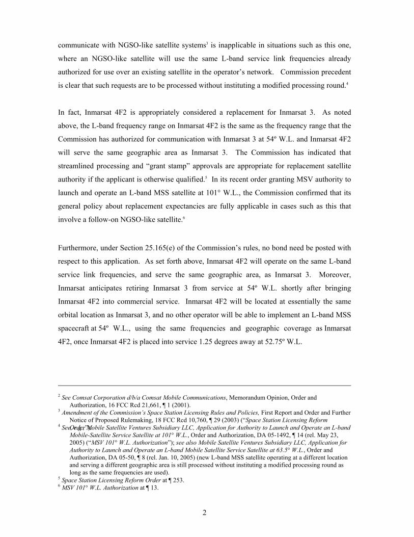
A.2 ORBITAL LOCATION
The Inmarsat 4F2 satellite will operate at the 52.75° W.L. geostationary orbital location. The
Inmarsat 3 satellite, which will be replaced by the Inmarsat 4F2 satellite, and over which the
Commission has already authorized the provision of service, currently operates at 54° W.L.
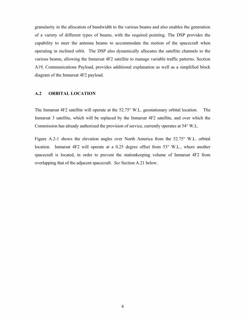
Figure A.2-1 shows the elevation angles over North America from the 52.75° W.L. orbital
location. Inmarsat 4F2 will operate at a 0.25 degree offset from 53° W.L., where another
spacecraft is located, in order to prevent the stationkeeping volume of Inmarsat 4F2 from
overlapping that of the adjacent spacecraft. See Section A.21 below.
5
Figure A.2-1 – Elevation Angles from the 52.75° W.L. Orbital Location
0°
0°
0°
1 0°
10°
20°
20°
30°
30°
40°
50°
SATS
OFT
-130.00 -120.00 -110.00 -100.00 -90.00 -80.00 -70.00 -60.00 -50.00East Longitude (Degrees)
10.00
20.00
30.00
40.00
50.00
60.00
70.00
Nor
th L
atitu
de (D
egre
es)
A.3 SATELLITE COVERAGE
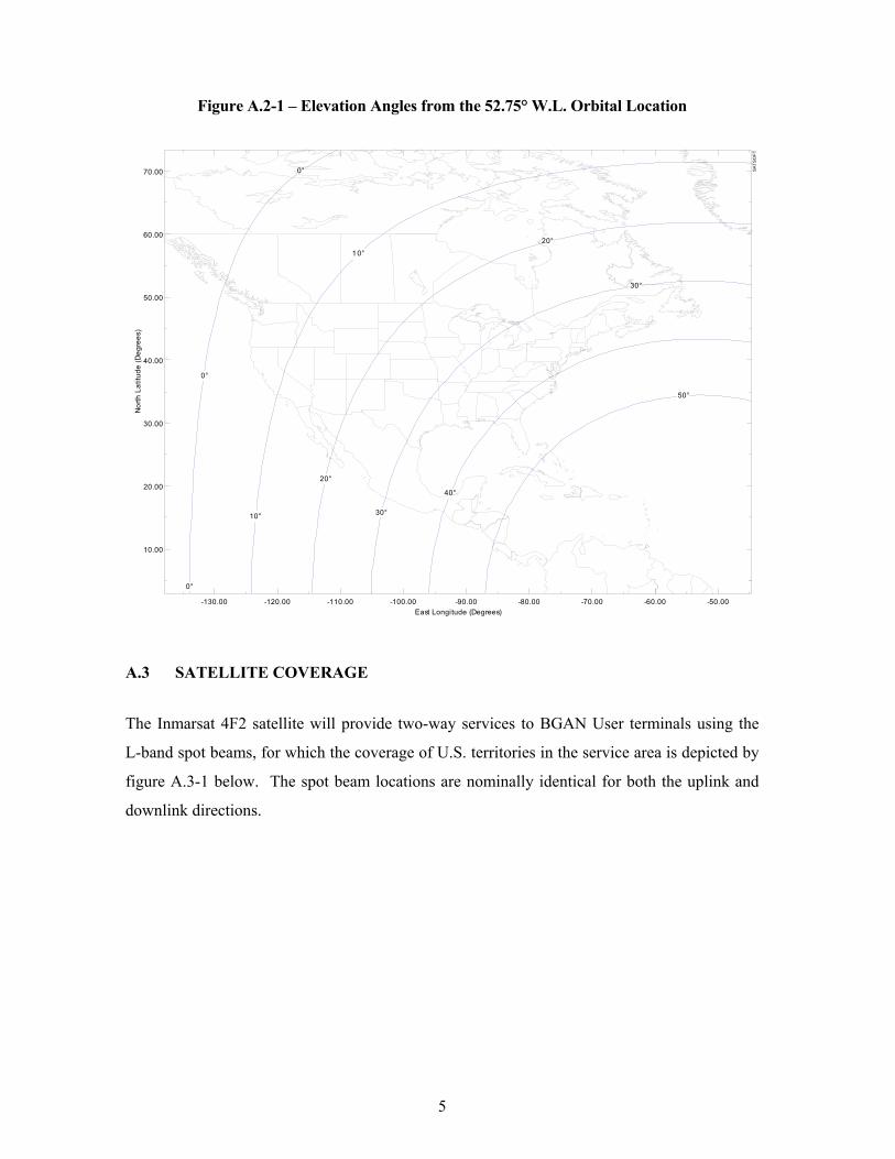
The Inmarsat 4F2 satellite will provide two-way services to BGAN User terminals using the
L-band spot beams, for which the coverage of U.S. territories in the service area is depicted by
figure A.3-1 below. The spot beam locations are nominally identical for both the uplink and
downlink directions.
6
Figure A.3-1 – BGAN L-band service link spot beams covering U.S. territory
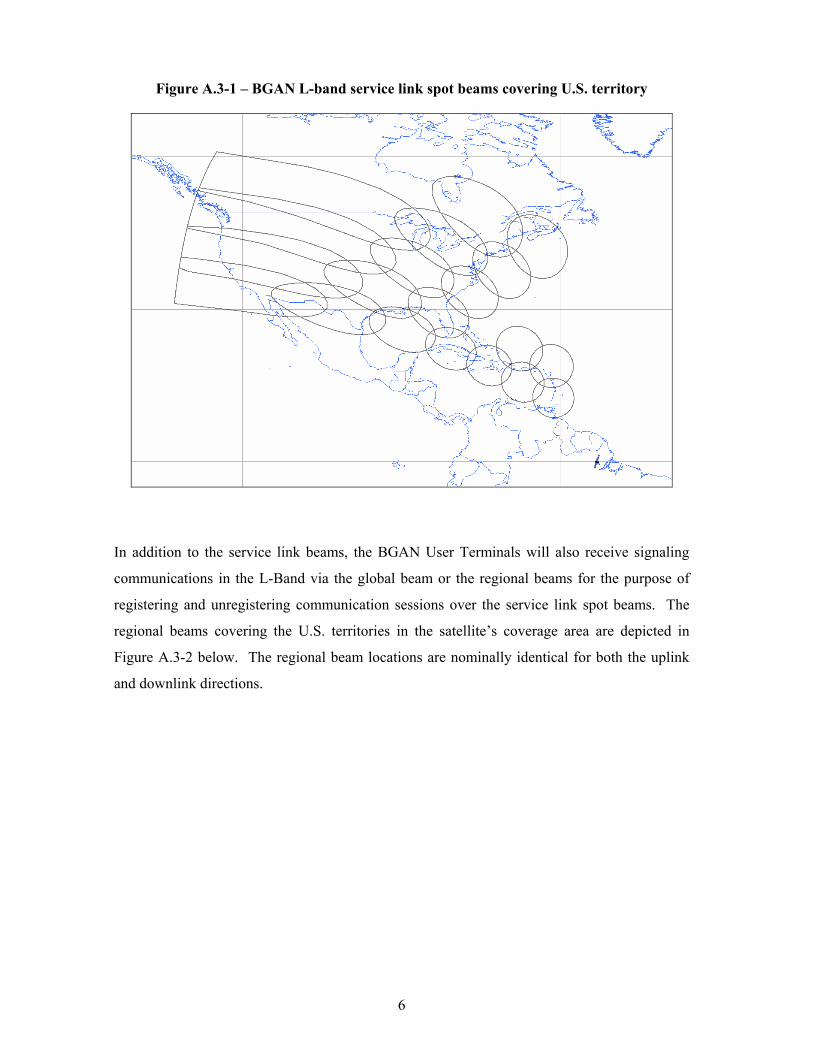
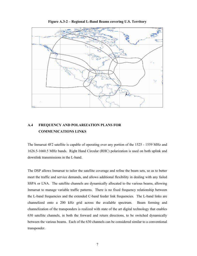
In addition to the service link beams, the BGAN User Terminals will also receive signaling
communications in the L-Band via the global beam or the regional beams for the purpose of
registering and unregistering communication sessions over the service link spot beams. The
regional beams covering the U.S. territories in the satellite’s coverage area are depicted in
Figure A.3-2 below. The regional beam locations are nominally identical for both the uplink
and downlink directions.
7
Figure A.3-2 – Regional L-Band Beams covering U.S. Territory
A.4 FREQUENCY AND POLARIZATION PLANS FOR
COMMUNICATIONS LINKS
The Inmarsat 4F2 satellite is capable of operating over any portion of the 1525 - 1559 MHz and
1626.5-1660.5 MHz bands. Right Hand Circular (RHC) polarization is used on both uplink and
downlink transmissions in the L-band.
The DSP allows Inmarsat to tailor the satellite coverage and refine the beam sets, so as to better
meet the traffic and service demands, and allows additional flexibility in dealing with any failed
SSPA or LNA. The satellite channels are dynamically allocated to the various beams, allowing
Inmarsat to manage variable traffic patterns. There is no fixed frequency relationship between
the L-band frequencies and the extended C-band feeder link frequencies. The L-band links are
channelized onto a 200 kHz grid across the available spectrum. Beam forming and
channelization of the transponders is realized with state of the art digital technology that enables
630 satellite channels, in both the forward and return directions, to be switched dynamically
between the various beams. Each of the 630 channels can be considered similar to a conventional
transponder.
8
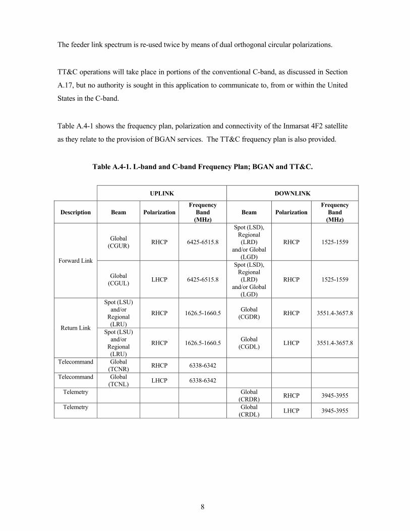
The feeder link spectrum is re-used twice by means of dual orthogonal circular polarizations.
TT&C operations will take place in portions of the conventional C-band, as discussed in Section
A.17, but no authority is sought in this application to communicate to, from or within the United
States in the C-band.
Table A.4-1 shows the frequency plan, polarization and connectivity of the Inmarsat 4F2 satellite
as they relate to the provision of BGAN services. The TT&C frequency plan is also provided.
Table A.4-1. L-band and C-band Frequency Plan; BGAN and TT&C.
UPLINK DOWNLINK
Description Beam Polarization Frequency
Band (MHz)
Beam Polarization Frequency
Band (MHz)
Global (CGUR) RHCP 6425-6515.8
Spot (LSD), Regional (LRD)
and/or Global (LGD)
RHCP 1525-1559
Forward Link
Global (CGUL) LHCP 6425-6515.8
Spot (LSD), Regional (LRD)
and/or Global (LGD)
RHCP 1525-1559
Spot (LSU) and/or
Regional (LRU)
RHCP 1626.5-1660.5 Global (CGDR) RHCP 3551.4-3657.8
Return Link Spot (LSU) and/or
Regional (LRU)
RHCP 1626.5-1660.5 Global (CGDL) LHCP 3551.4-3657.8
Telecommand Global (TCNR) RHCP 6338-6342
Telecommand Global (TCNL) LHCP 6338-6342
Telemetry Global (CRDR) RHCP 3945-3955
Telemetry Global (CRDL) LHCP 3945-3955
9
A.5 SATELLITE TRANSMIT CAPABILITY
A.5.1 Feeder Downlink
The signals received by the L-band antenna are amplified by the low noise amplifiers (LNA)
and fed to the L-band pre-processor, which performs the required filtering and down-
conversion of the signals to baseband, before passing them to A/D converters that feed the
DSP. The DSP performs the required channelizing and beam-forming functions, and passes the
signals to the required D/A converters, which then feed the C-band up-converter. High power
SSPA’s, operating in a 6x4 redundancy configuration, are used on the C-band output section to
provide the required amount of power to the C-band antenna.
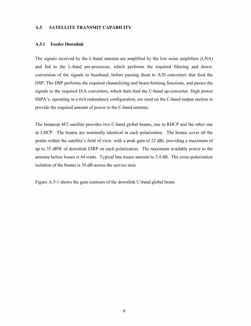
The Inmarsat 4F2 satellite provides two C-band global beams, one in RHCP and the other one
in LHCP. The beams are nominally identical in each polarization. The beams cover all the
points within the satellite’s field of view, with a peak gain of 22 dBi, providing a maximum of
up to 35 dBW of downlink EIRP on each polarization. The maximum available power to the
antenna before losses is 44 watts. Typical line losses amount to 3.4 dB. The cross-polarization
isolation of the beams is 30 dB across the service area.
Figure A.5-1 shows the gain contours of the downlink C-band global beam.
10
Figure A.5-1 – Downlink C-Band Global Beam Gain Contours
(Contours shown are -2 and -4 dB relative to the beam peak)
0.00
-4.00
-2.00
A.5.2 Service Downlink
On the forward C-to-L link, the signals received from the satellite gateway earth station are
received by the C-band antenna, filtered and passed to the C-band receiver. The amplified
signal is filtered and down converted by the C-band down converter and, after going through
the required analog-to-digital (A/D) converters, is fed to the DSP. The DSP is responsible for
breaking the signals into the appropriate 200 kHz channels, and for applying the correct beam
forming coefficients to each channel. The channelized and beam-formed signals, after being
converted to analog signals by digital-to-analog (D/A) converters, are then fed to the L- band
post-processor, which employ SAW technology to filter and converts the signals to L- band,
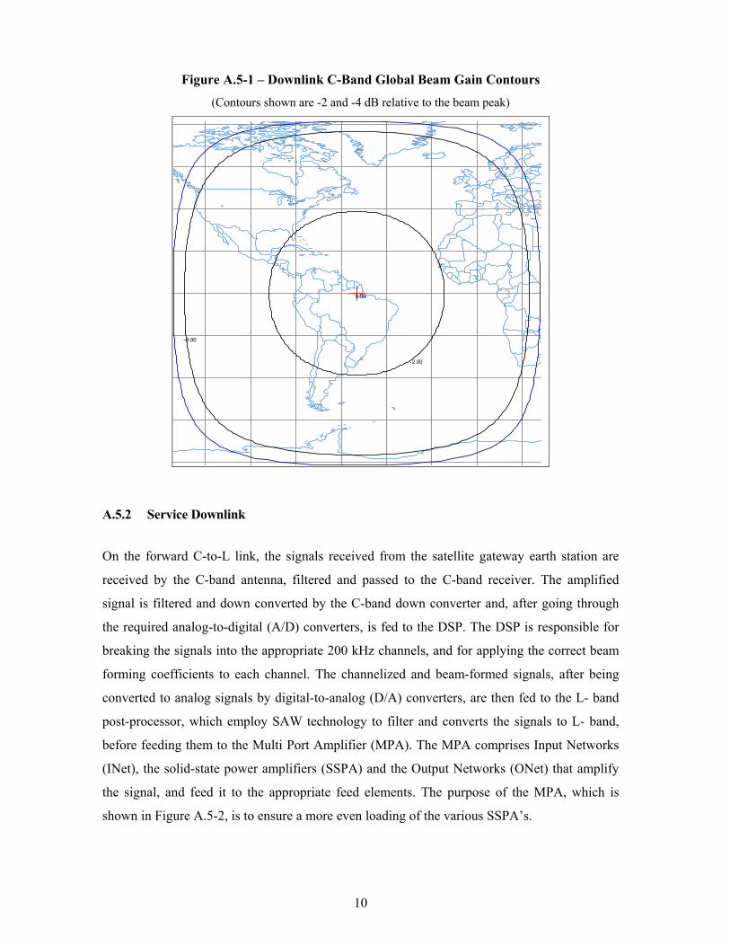
before feeding them to the Multi Port Amplifier (MPA). The MPA comprises Input Networks
(INet), the solid-state power amplifiers (SSPA) and the Output Networks (ONet) that amplify
the signal, and feed it to the appropriate feed elements. The purpose of the MPA, which is
shown in Figure A.5-2, is to ensure a more even loading of the various SSPA’s.
11
Figure A.5-2 – The Multi Port Amplifier
There are 120 active SSPA’s, configured in groups of 5x4 to provide the required redundancy,
resulting in a total of 150 SSPA’s per spacecraft. Figure A.5-3 provides the gain contours of a
typical spot beam. The spot beams transmit in RHCP only. The peak antenna gain of these
beams ranges from 40 dBi to 42 dBi, depending on their pointing direction.
The maximum available power to the antenna before losses is 1800 watts, on which there is an
average line loss of 4.1 dB. This total available power can be dynamically apportioned
between the three categories of service beams, whose nominal peak gains are 22 dBi, 34 dBi
and 42 dBi for the global, regional and spot beams respectively. The maximum attainable
downlink EIRP values are 43 dBW, 58 dBW, and 70 dBW for the global, regional and spot
beams, respectively. These maximum downlink EIRP levels cannot occur simultaneously. In
the event one of the maximum levels occurs, there will be a corresponding reduction in the
power available to the other beam types.
12
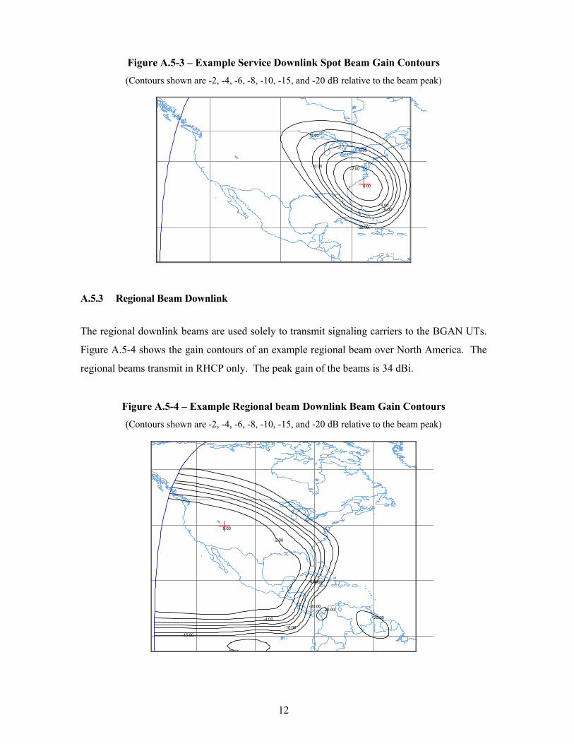
Figure A.5-3 – Example Service Downlink Spot Beam Gain Contours
(Contours shown are -2, -4, -6, -8, -10, -15, and -20 dB relative to the beam peak)
0.00
-20.00
-15.00
-10.00
-8.00
-6.00-4.00
-2.00
A.5.3 Regional Beam Downlink
The regional downlink beams are used solely to transmit signaling carriers to the BGAN UTs.
Figure A.5-4 shows the gain contours of an example regional beam over North America. The
regional beams transmit in RHCP only. The peak gain of the beams is 34 dBi.
Figure A.5-4 – Example Regional beam Downlink Beam Gain Contours
(Contours shown are -2, -4, -6, -8, -10, -15, and -20 dB relative to the beam peak)
0.00
-20.00
-20.00
20 00
-20.00
-15.00
-10.00
-8.00-6.00
-4.00
-2.00
13
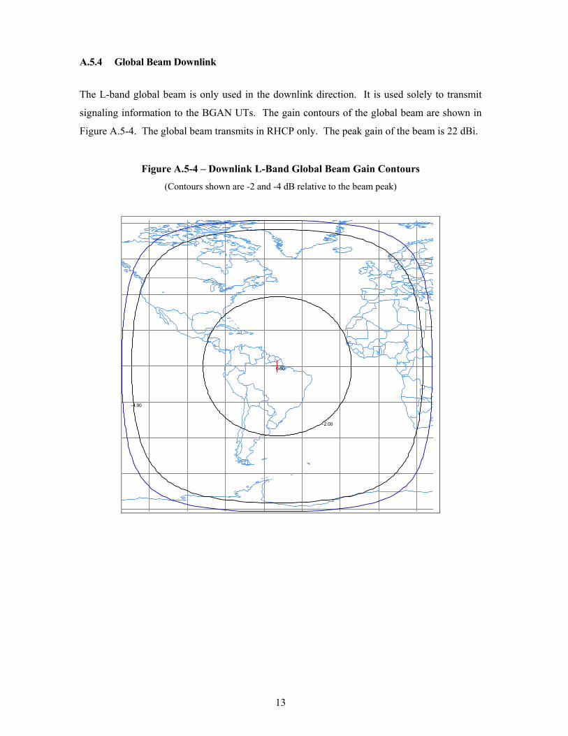
A.5.4 Global Beam Downlink
The L-band global beam is only used in the downlink direction. It is used solely to transmit
signaling information to the BGAN UTs. The gain contours of the global beam are shown in
Figure A.5-4. The global beam transmits in RHCP only. The peak gain of the beam is 22 dBi.
Figure A.5-4 – Downlink L-Band Global Beam Gain Contours
(Contours shown are -2 and -4 dB relative to the beam peak)
0.00
-4.00
-2.00
14
A.6 SATELLITE RECEIVE CAPABILITY
A.6.1 Feeder Uplink
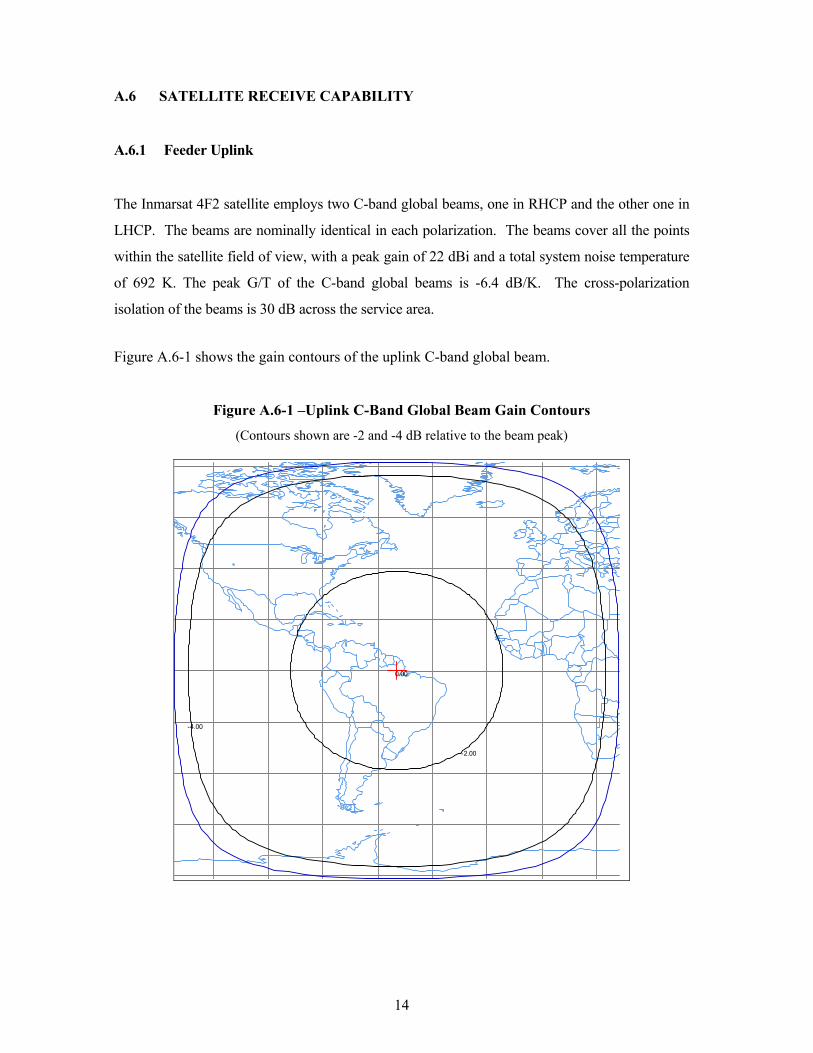
The Inmarsat 4F2 satellite employs two C-band global beams, one in RHCP and the other one in
LHCP. The beams are nominally identical in each polarization. The beams cover all the points
within the satellite field of view, with a peak gain of 22 dBi and a total system noise temperature
of 692 K. The peak G/T of the C-band global beams is -6.4 dB/K. The cross-polarization
isolation of the beams is 30 dB across the service area.
Figure A.6-1 shows the gain contours of the uplink C-band global beam.
Figure A.6-1 –Uplink C-Band Global Beam Gain Contours
(Contours shown are -2 and -4 dB relative to the beam peak)
0.00
-4.00
-2.00
15
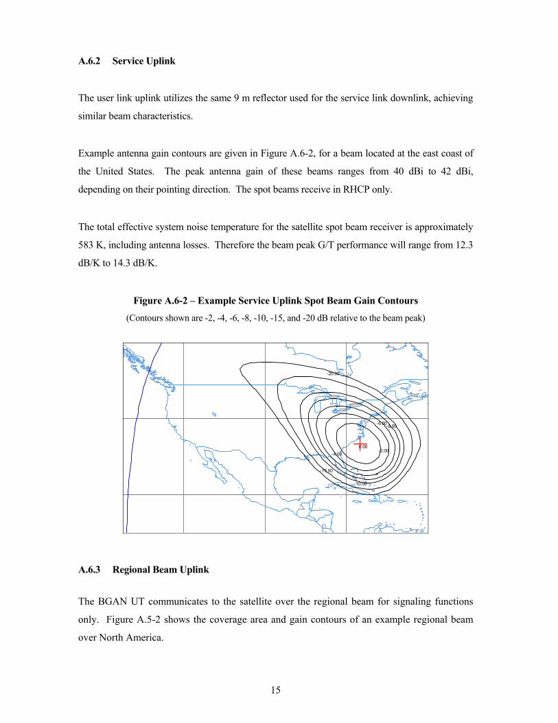
A.6.2 Service Uplink
The user link uplink utilizes the same 9 m reflector used for the service link downlink, achieving
similar beam characteristics.
Example antenna gain contours are given in Figure A.6-2, for a beam located at the east coast of
the United States. The peak antenna gain of these beams ranges from 40 dBi to 42 dBi,
depending on their pointing direction. The spot beams receive in RHCP only.
The total effective system noise temperature for the satellite spot beam receiver is approximately
583 K, including antenna losses. Therefore the beam peak G/T performance will range from 12.3
dB/K to 14.3 dB/K.
Figure A.6-2 – Example Service Uplink Spot Beam Gain Contours
(Contours shown are -2, -4, -6, -8, -10, -15, and -20 dB relative to the beam peak)
0.00
-20.00
-15.00
-10.00
-8.00-6.00
-4.00-2.00
A.6.3 Regional Beam Uplink
The BGAN UT communicates to the satellite over the regional beam for signaling functions
only. Figure A.5-2 shows the coverage area and gain contours of an example regional beam
over North America.
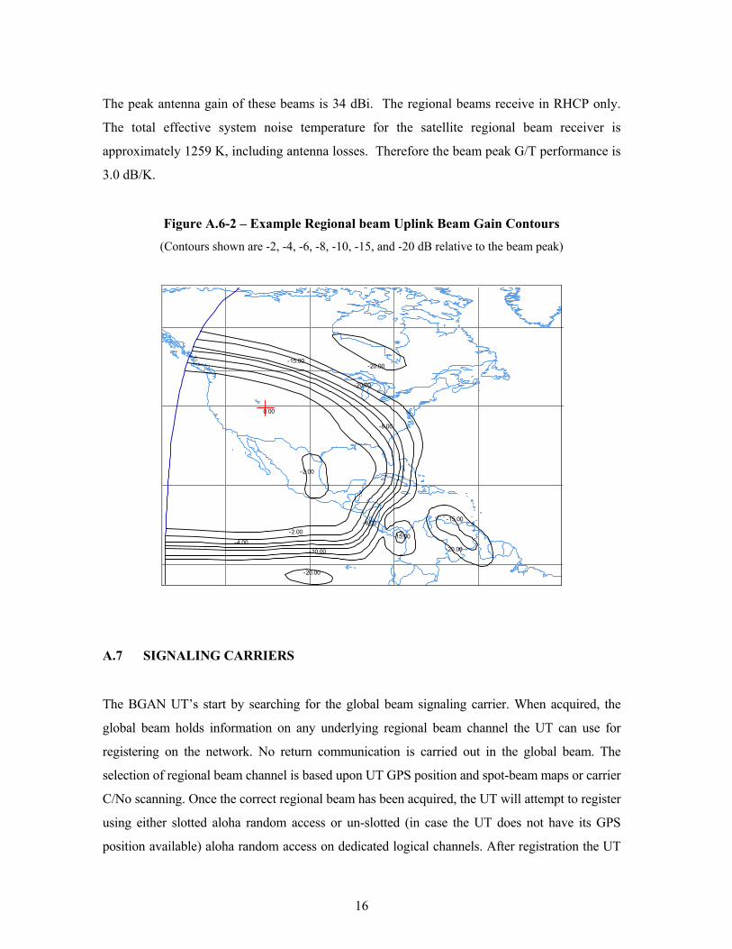
16
The peak antenna gain of these beams is 34 dBi. The regional beams receive in RHCP only.
The total effective system noise temperature for the satellite regional beam receiver is
approximately 1259 K, including antenna losses. Therefore the beam peak G/T performance is
3.0 dB/K.
Figure A.6-2 – Example Regional beam Uplink Beam Gain Contours
(Contours shown are -2, -4, -6, -8, -10, -15, and -20 dB relative to the beam peak)
0.00
-20.00
-20.00
-20.00
-20.00
-15.00
-15.00
-15.00
-10.00
-8.00
-6.00
-4.00
-2.00
-2.00
A.7 SIGNALING CARRIERS
The BGAN UT’s start by searching for the global beam signaling carrier. When acquired, the
global beam holds information on any underlying regional beam channel the UT can use for
registering on the network. No return communication is carried out in the global beam. The
selection of regional beam channel is based upon UT GPS position and spot-beam maps or carrier
C/No scanning. Once the correct regional beam has been acquired, the UT will attempt to register
using either slotted aloha random access or un-slotted (in case the UT does not have its GPS
position available) aloha random access on dedicated logical channels. After registration the UT
17
is handed over to a spot beam whenever a communications session is started. After the
communications session has ended the UT is moved back to the regional beam to preserve
resources in the spot beams.
Global beam Signaling:
The Inmarsat 4F2 satellite will transmit one 12.5 KHz signaling carrier via the global beam. The
carrier is transmitted continuously at a steady power level.
Regional Beam Signaling:
In the regional beam, two 50 kHz signaling carrier types are used for the BGAN. The modulation
is either 16QAM or QPSK.
The Return direction is used for the UT’s to register onto the network. Depending on the UT
Class (1, 2 or 3), the UT will register using any combination of burst characteristics that closes
the link. The return signaling carriers are either 25 kHz or 50 kHz and the modulation can either
be QPSK or 16QAM.
A.8 TRANSPONDER GAIN CONTROL AND SATURATING FLUX DENSITY
In order to ensure that the drive level to the SSPA’s is kept within the specified range, and the
linearity performance is maintained, a power control loop samples the current driven by the L-
band SSPA’s on the forward link, and controls the gain at the C-band receivers, while on the
return link automatic level control circuits are used on the C-band SSPA’s. The gain of a
transmission channel is defined at the center frequency, and includes receive and transmit
antenna gains at edge of coverage, and assumes operation of the power amplifiers in the linear
region.
For channels using the spot beams, it is possible to command the gain of any transmission
channel on both the forward link and return links between 176 dB and 192 dB. For channels
using the regional beams or the global beam, it is possible to command the gain of any
transmission channel, on both the forward link and the return link, between 160 dB and 176
dB.

18
On the forward link the commandable gain step is 1 dB, while on the return link the gain step is
2 dB.
The minimum SFD for each uplink beam type is included in the Schedule S form. The SFDs
vary over the 16 dB attenuation range.
A.9 UNWANTED EMISSIONS
The out-of-band emissions will not exceed the limits of §25.202(f) (1), (2) and (3).
A.10 EMISSION DESIGNATORS AND ALLOCATED BANDWIDTH OF EMISSION
The communications signals will utilize carriers of varying bandwidths and different modulation
schemes. All communications carriers will be digitally modulated. Typical emission designators
to be used with the BGAN service and their associated allocated bandwidths are provided in
Table A.10-1.
Table A.10-1. Emission Designators and Allocated Bandwidths
Emission Designator Allocated Bandwidth
200KG7W 200 kHz
200KD7W 200 kHz
50K0G7W 50 kHz
50K0D7W 50 kHz
25K0G7W 25 kHz
12K5G7W 12.5 kHz
19
A.11 EARTH STATIONS
A.11.1 User Terminals
The Inmarsat 4F2 satellite is designed to operate with a range of user terminals meaning that
customers will have a choice of different BGAN terminals. The user terminals have been
designed and developed together with selected manufacturers and will deliver a differentiated
range of mobile communication devices to suit the varying needs of new and existing customers.
The available terminals will vary in price, performance and portability, in order to address a
broad range of different market requirements. These range from experienced legacy users of
satellite communications with more advanced needs, to new users in new industry sectors who
are considering a satellite solution for the first time.
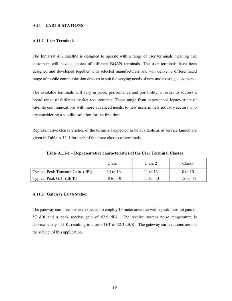
Representative characteristics of the terminals expected to be available as of service launch are
given in Table A.11-1 for each of the three classes of terminals.
Table A.11-1 – Representative characteristics of the User Terminal Classes
Class 1 Class 2 Class3
Typical Peak Transmit Gain (dBi) 14 to 16 11 to 13 8 to 10 Typical Peak G/T (dB/K) -8 to -10 -11 to -13 -15 to -17
A.11.2 Gateway Earth Station
The gateway earth stations are expected to employ 13 meter antennas with a peak transmit gain of
57 dBi and a peak receive gain of 52.9 dBi. The receive system noise temperature is
approximately 115 K, resulting in a peak G/T of 32.3 dB/K. The gateway earth stations are not
the subject of this application.
20
A.12 LINK BUDGETS
A.12.1 Communications Links
The BGAN carriers are QPSK or 16-QAM modulated and use adaptive coding that provides a
data rate of up to 492 kBits/second. The access technique is frequency division duplex - time
division multiple access (“FDD-TDMA”).
The BGAN communication carriers in the spot beams are transmitted in a 200 kHz channel.
Within a given channel, the Inmarsat 4F2 network is capable of delivering a range of data rates
by assigning one of the available FEC rates and associated C/N requirements, depending on
available satellite EIRP and G/T at a specific location, fading loss, user terminal antenna G/T, and
elevation angle. If a high data rate could not be supported due to, for example, unavailability of
the required satellite EIRP or G/T at a specific location, or lower G/T of a certain terminal type,
then a lower user data rate will be assigned to that particular transmission link.
The signaling carriers in the regional beams and global beams are transmitted with bandwidths of
50 kHz and 12.5 kHz, respectively.
Tables A.12-1 through A.12-3 show representative forward link budgets for the communication
carriers to the Class-1, Class-2, and Class-3 user terminals, respectively, via the downlink spot
beams.
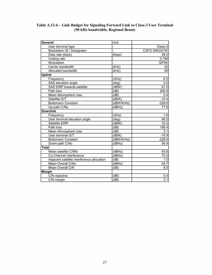
Tables A.12-4 through A.12-6 show representative forward link budgets for the signaling carriers
to the Class-1, Class-2, and Class-3 user terminals, respectively, via a downlink regional beam.
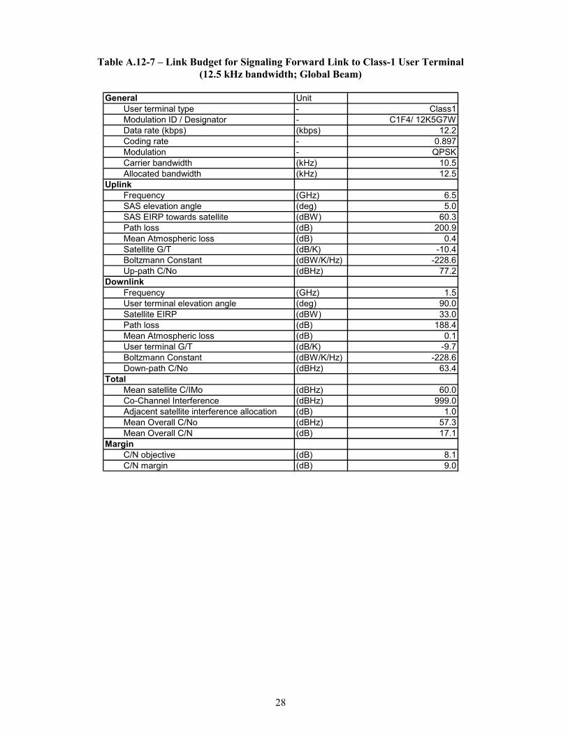
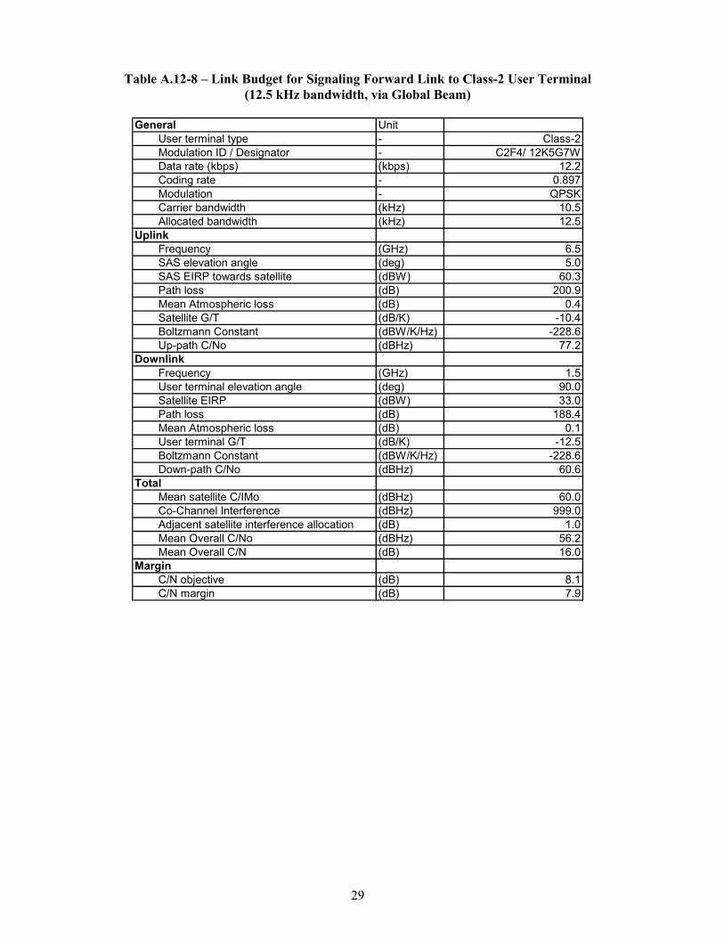
Tables A.12-7 through A.12-9 show representative forward link budgets for the signaling carriers
to the Class-1, Class-2, and Class-3 user terminals, respectively, via the downlink global beam.
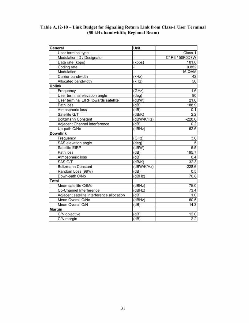
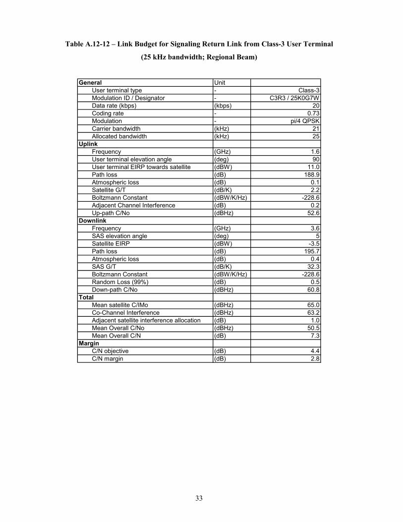
Tables A.12-10 through A.12-12 show representative return link budgets for the signaling carriers
from the Class-1, Class-2, and Class-3 user terminals, respectively, to a receive regional beam.
21
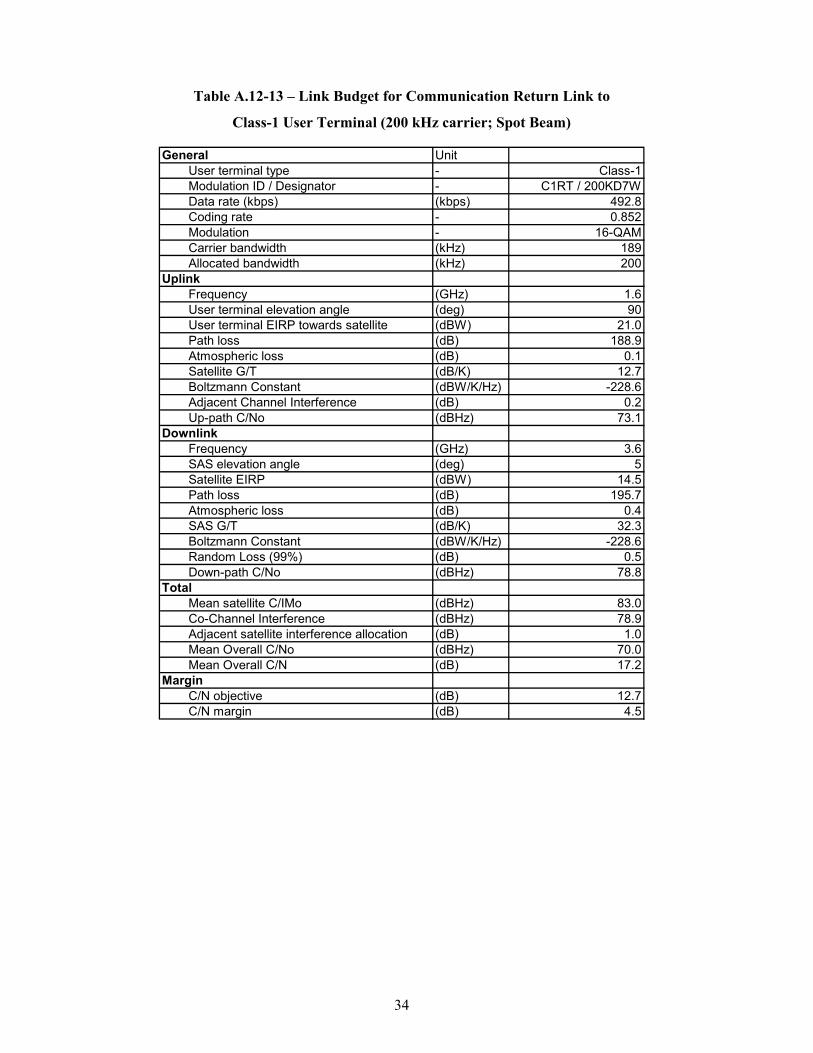
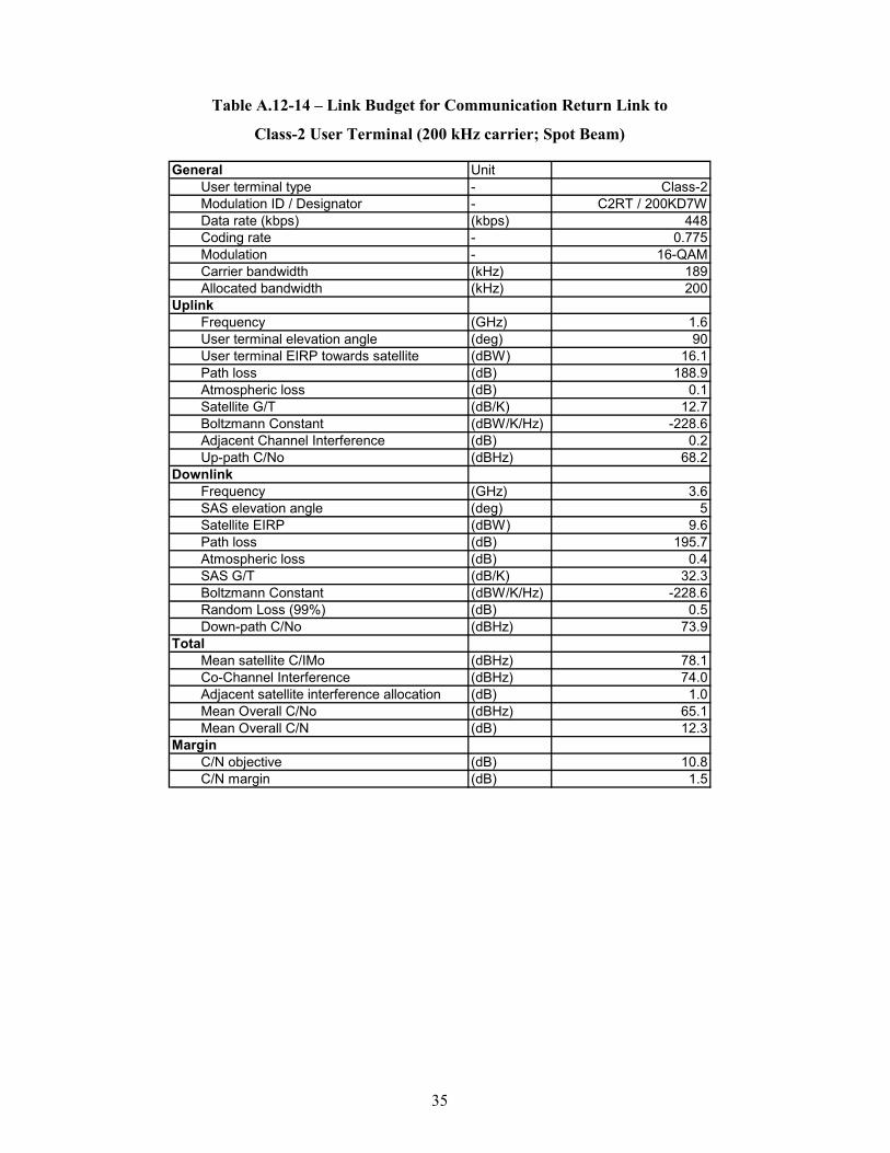
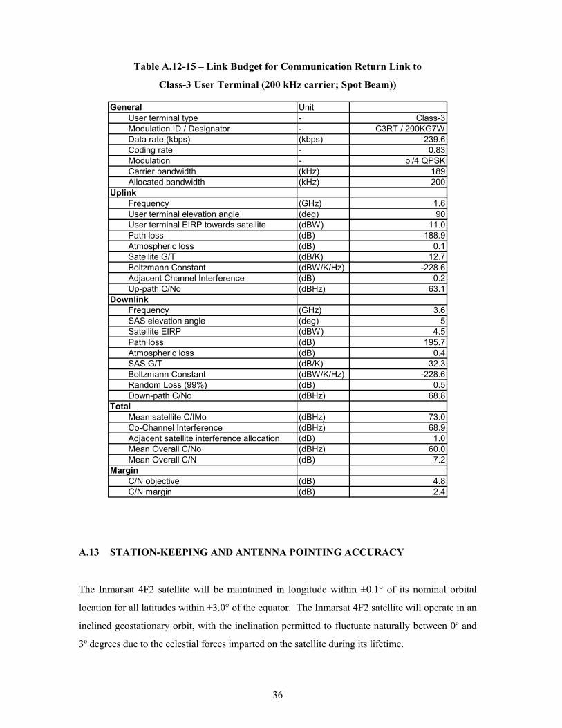
Tables A.12-13 through A.12-15 show representative return link budgets for the communication
carriers from the Class-1, Class-2, and Class-3 user terminals, respectively, to a receive spot
beam.
(Note: In the following link budget tables the Satellite gateway earth station is designated as the
“SAS”, Satellite Access Stations.)

22
Table A.12-1 – Link Budget for Communication Forward Link to
Class-1 User Terminal (200 kHz carrier; Spot Beam)
General UnitUser terminal type - Class1Modulation ID / Designator - C1F2/ 200KD7WData rate (kbps) (kbps) 492Coding rate - 0.822Modulation - 16-QAMCarrier bandwidth (kHz) 189Allocated bandwidth (kHz) 200
UplinkFrequency (GHz) 6.5SAS elevation angle (deg) 5.0SAS EIRP towards satellite (dBW) 57.3Path loss (dB) 200.9Mean Atmospheric loss (dB) 0.4Satellite G/T (dB/K) -10.4Boltzmann Constant (dBW/K/Hz) -228.6Up-path C/No (dBHz) 74.2
DownlinkFrequency (GHz) 1.5User terminal elevation angle (deg) 90.0Satellite EIRP (dBW) 44.5Path loss (dB) 188.4Mean Atmospheric loss (dB) 0.1User terminal G/T (dB/K) -9.7Boltzmann Constant (dBW/K/Hz) -228.6Down-path C/No (dBHz) 74.9
TotalMean satellite C/IMo (dBHz) 71.9Co-Channel Interference (dBHz) 74.0Adjacent satellite interference allocation (dB) 1.0Mean Overall C/No (dBHz) 66.6Mean Overall C/N (dB) 13.8
MarginC/N objective (dB) 12.3C/N margin (dB) 1.5
23
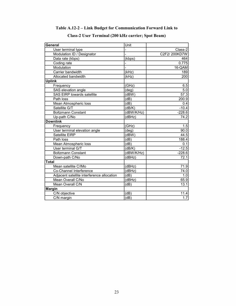
Table A.12-2 – Link Budget for Communication Forward Link to
Class-2 User Terminal (200 kHz carrier; Spot Beam)
General UnitUser terminal type - Class-2Modulation ID / Designator - C2F2/ 200KD7WData rate (kbps) (kbps) 464Coding rate - 0.775Modulation - 16-QAMCarrier bandwidth (kHz) 189Allocated bandwidth (kHz) 200
UplinkFrequency (GHz) 6.5SAS elevation angle (deg) 5.0SAS EIRP towards satellite (dBW) 57.3Path loss (dB) 200.9Mean Atmospheric loss (dB) 0.4Satellite G/T (dB/K) -10.4Boltzmann Constant (dBW/K/Hz) -228.6Up-path C/No (dBHz) 74.2
DownlinkFrequency (GHz) 1.5User terminal elevation angle (deg) 90.0Satellite EIRP (dBW) 44.5Path loss (dB) 188.4Mean Atmospheric loss (dB) 0.1User terminal G/T (dB/K) -12.5Boltzmann Constant (dBW/K/Hz) -228.6Down-path C/No (dBHz) 72.1
TotalMean satellite C/IMo (dBHz) 71.9Co-Channel Interference (dBHz) 74.0Adjacent satellite interference allocation (dB) 1.0Mean Overall C/No (dBHz) 65.9Mean Overall C/N (dB) 13.1
MarginC/N objective (dB) 11.4C/N margin (dB) 1.7
24
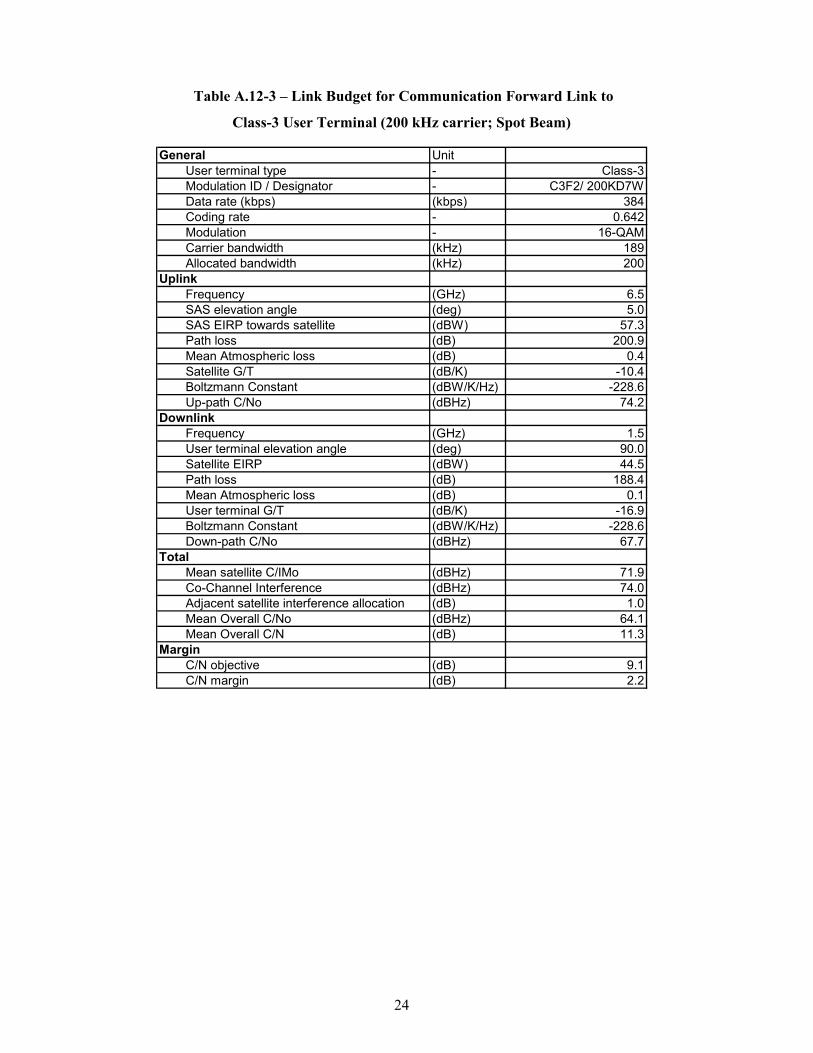
Table A.12-3 – Link Budget for Communication Forward Link to
Class-3 User Terminal (200 kHz carrier; Spot Beam)
General UnitUser terminal type - Class-3Modulation ID / Designator - C3F2/ 200KD7WData rate (kbps) (kbps) 384Coding rate - 0.642Modulation - 16-QAMCarrier bandwidth (kHz) 189Allocated bandwidth (kHz) 200
UplinkFrequency (GHz) 6.5SAS elevation angle (deg) 5.0SAS EIRP towards satellite (dBW) 57.3Path loss (dB) 200.9Mean Atmospheric loss (dB) 0.4Satellite G/T (dB/K) -10.4Boltzmann Constant (dBW/K/Hz) -228.6Up-path C/No (dBHz) 74.2
DownlinkFrequency (GHz) 1.5User terminal elevation angle (deg) 90.0Satellite EIRP (dBW) 44.5Path loss (dB) 188.4Mean Atmospheric loss (dB) 0.1User terminal G/T (dB/K) -16.9Boltzmann Constant (dBW/K/Hz) -228.6Down-path C/No (dBHz) 67.7
TotalMean satellite C/IMo (dBHz) 71.9Co-Channel Interference (dBHz) 74.0Adjacent satellite interference allocation (dB) 1.0Mean Overall C/No (dBHz) 64.1Mean Overall C/N (dB) 11.3
MarginC/N objective (dB) 9.1C/N margin (dB) 2.2
25
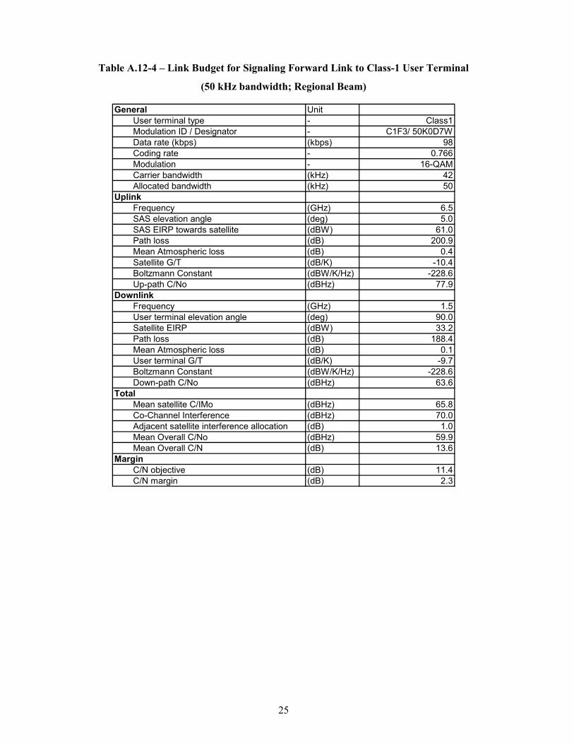
Table A.12-4 – Link Budget for Signaling Forward Link to Class-1 User Terminal
(50 kHz bandwidth; Regional Beam)
General UnitUser terminal type - Class1Modulation ID / Designator - C1F3/ 50K0D7WData rate (kbps) (kbps) 98Coding rate - 0.766Modulation - 16-QAMCarrier bandwidth (kHz) 42Allocated bandwidth (kHz) 50
UplinkFrequency (GHz) 6.5SAS elevation angle (deg) 5.0SAS EIRP towards satellite (dBW) 61.0Path loss (dB) 200.9Mean Atmospheric loss (dB) 0.4Satellite G/T (dB/K) -10.4Boltzmann Constant (dBW/K/Hz) -228.6Up-path C/No (dBHz) 77.9
DownlinkFrequency (GHz) 1.5User terminal elevation angle (deg) 90.0Satellite EIRP (dBW) 33.2Path loss (dB) 188.4Mean Atmospheric loss (dB) 0.1User terminal G/T (dB/K) -9.7Boltzmann Constant (dBW/K/Hz) -228.6Down-path C/No (dBHz) 63.6
TotalMean satellite C/IMo (dBHz) 65.8Co-Channel Interference (dBHz) 70.0Adjacent satellite interference allocation (dB) 1.0Mean Overall C/No (dBHz) 59.9Mean Overall C/N (dB) 13.6
MarginC/N objective (dB) 11.4C/N margin (dB) 2.3

26
Table A.12-5 – Link Budget for Signaling Forward Link to Class-2 User Terminal (50 kHz bandwidth; Regional Beam)
General Unit
User terminal type - Class-2Modulation ID / Designator - C2F3/ 50K0D7WData rate (kbps) (kbps) 90Coding rate - 0.703Modulation - 16-QAMCarrier bandwidth (kHz) 42Allocated bandwidth (kHz) 50
UplinkFrequency (GHz) 6.5SAS elevation angle (deg) 5.0SAS EIRP towards satellite (dBW) 61.0Path loss (dB) 200.9Mean Atmospheric loss (dB) 0.4Satellite G/T (dB/K) -10.4Boltzmann Constant (dBW/K/Hz) -228.6Up-path C/No (dBHz) 77.9
DownlinkFrequency (GHz) 1.5User terminal elevation angle (deg) 90.0Satellite EIRP (dBW) 33.2Path loss (dB) 188.4Mean Atmospheric loss (dB) 0.1User terminal G/T (dB/K) -12.5Boltzmann Constant (dBW/K/Hz) -228.6Down-path C/No (dBHz) 60.8
TotalMean satellite C/IMo (dBHz) 65.8Co-Channel Interference (dBHz) 70.0Adjacent satellite interference allocation (dB) 1.0Mean Overall C/No (dBHz) 58.2Mean Overall C/N (dB) 11.9
MarginC/N objective (dB) 10.3C/N margin (dB) 1.7
27
Table A.12-6 – Link Budget for Signaling Forward Link to Class-3 User Terminal (50 kHz bandwidth; Regional Beam)
General Unit
User terminal type - Class-3Modulation ID / Designator - C3F3/ 50K0G7WData rate (kbps) (kbps) 49.2Coding rate - 0.796Modulation - QPSKCarrier bandwidth (kHz) 42Allocated bandwidth (kHz) 50
UplinkFrequency (GHz) 6.5SAS elevation angle (deg) 5.0SAS EIRP towards satellite (dBW) 61.0Path loss (dB) 200.9Mean Atmospheric loss (dB) 0.4Satellite G/T (dB/K) -10.4Boltzmann Constant (dBW/K/Hz) -228.6Up-path C/No (dBHz) 77.9
DownlinkFrequency (GHz) 1.5User terminal elevation angle (deg) 90.0Satellite EIRP (dBW) 33.2Path loss (dB) 188.4Mean Atmospheric loss (dB) 0.1User terminal G/T (dB/K) -16.9Boltzmann Constant (dBW/K/Hz) -228.6Down-path C/No (dBHz) 56.4
TotalMean satellite C/IMo (dBHz) 65.8Co-Channel Interference (dBHz) 70.0Adjacent satellite interference allocation (dB) 1.0Mean Overall C/No (dBHz) 54.7Mean Overall C/N (dB) 8.5
MarginC/N objective (dB) 5.4C/N margin (dB) 3.1
28
Table A.12-7 – Link Budget for Signaling Forward Link to Class-1 User Terminal (12.5 kHz bandwidth; Global Beam)
General Unit
User terminal type - Class1Modulation ID / Designator - C1F4/ 12K5G7WData rate (kbps) (kbps) 12.2Coding rate - 0.897Modulation - QPSKCarrier bandwidth (kHz) 10.5Allocated bandwidth (kHz) 12.5
UplinkFrequency (GHz) 6.5SAS elevation angle (deg) 5.0SAS EIRP towards satellite (dBW) 60.3Path loss (dB) 200.9Mean Atmospheric loss (dB) 0.4Satellite G/T (dB/K) -10.4Boltzmann Constant (dBW/K/Hz) -228.6Up-path C/No (dBHz) 77.2
DownlinkFrequency (GHz) 1.5User terminal elevation angle (deg) 90.0Satellite EIRP (dBW) 33.0Path loss (dB) 188.4Mean Atmospheric loss (dB) 0.1User terminal G/T (dB/K) -9.7Boltzmann Constant (dBW/K/Hz) -228.6Down-path C/No (dBHz) 63.4
TotalMean satellite C/IMo (dBHz) 60.0Co-Channel Interference (dBHz) 999.0Adjacent satellite interference allocation (dB) 1.0Mean Overall C/No (dBHz) 57.3Mean Overall C/N (dB) 17.1
MarginC/N objective (dB) 8.1C/N margin (dB) 9.0
29
Table A.12-8 – Link Budget for Signaling Forward Link to Class-2 User Terminal (12.5 kHz bandwidth, via Global Beam)
General Unit
User terminal type - Class-2Modulation ID / Designator - C2F4/ 12K5G7WData rate (kbps) (kbps) 12.2Coding rate - 0.897Modulation - QPSKCarrier bandwidth (kHz) 10.5Allocated bandwidth (kHz) 12.5
UplinkFrequency (GHz) 6.5SAS elevation angle (deg) 5.0SAS EIRP towards satellite (dBW) 60.3Path loss (dB) 200.9Mean Atmospheric loss (dB) 0.4Satellite G/T (dB/K) -10.4Boltzmann Constant (dBW/K/Hz) -228.6Up-path C/No (dBHz) 77.2
DownlinkFrequency (GHz) 1.5User terminal elevation angle (deg) 90.0Satellite EIRP (dBW) 33.0Path loss (dB) 188.4Mean Atmospheric loss (dB) 0.1User terminal G/T (dB/K) -12.5Boltzmann Constant (dBW/K/Hz) -228.6Down-path C/No (dBHz) 60.6
TotalMean satellite C/IMo (dBHz) 60.0Co-Channel Interference (dBHz) 999.0Adjacent satellite interference allocation (dB) 1.0Mean Overall C/No (dBHz) 56.2Mean Overall C/N (dB) 16.0
MarginC/N objective (dB) 8.1C/N margin (dB) 7.9

30
Table A.12-9 – Link Budget for Signaling Forward Link to Class-3 User Terminal (12.5 kHz bandwidth, via Global Beam)
General Unit
User terminal type - Class-3Modulation ID / Designator - C3F4/ 12K5G7WData rate (kbps) (kbps) 12.2Coding rate - 0.897Modulation - QPSKCarrier bandwidth (kHz) 10.5Allocated bandwidth (kHz) 12.5
UplinkFrequency (GHz) 6.5SAS elevation angle (deg) 5.0SAS EIRP towards satellite (dBW) 60.3Path loss (dB) 200.9Mean Atmospheric loss (dB) 0.4Satellite G/T (dB/K) -10.4Boltzmann Constant (dBW/K/Hz) -228.6Up-path C/No (dBHz) 77.2
DownlinkFrequency (GHz) 1.5User terminal elevation angle (deg) 90.0Satellite EIRP (dBW) 33.0Path loss (dB) 188.4Mean Atmospheric loss (dB) 0.1User terminal G/T (dB/K) -16.9Boltzmann Constant (dBW/K/Hz) -228.6Down-path C/No (dBHz) 56.2
TotalMean satellite C/IMo (dBHz) 60.0Co-Channel Interference (dBHz) 999.0Adjacent satellite interference allocation (dB) 1.0Mean Overall C/No (dBHz) 53.7Mean Overall C/N (dB) 13.4
MarginC/N objective (dB) 8.1C/N margin (dB) 5.4
31
Table A.12-10 – Link Budget for Signaling Return Link from Class-1 User Terminal (50 kHz bandwidth; Regional Beam)
General UnitUser terminal type - Class-1Modulation ID / Designator - C1R3 / 50K0D7WData rate (kbps) (kbps) 101.6Coding rate - 0.852Modulation - 16-QAMCarrier bandwidth (kHz) 42Allocated bandwidth (kHz) 50
UplinkFrequency (GHz) 1.6User terminal elevation angle (deg) 90User terminal EIRP towards satellite (dBW) 21.0Path loss (dB) 188.9Atmospheric loss (dB) 0.1Satellite G/T (dB/K) 2.2Boltzmann Constant (dBW/K/Hz) -228.6Adjacent Channel Interference (dB) 0.2Up-path C/No (dBHz) 62.6
DownlinkFrequency (GHz) 3.6SAS elevation angle (deg) 5Satellite EIRP (dBW) 6.5Path loss (dB) 195.7Atmospheric loss (dB) 0.4SAS G/T (dB/K) 32.3Boltzmann Constant (dBW/K/Hz) -228.6Random Loss (99%) (dB) 0.5Down-path C/No (dBHz) 70.8
TotalMean satellite C/IMo (dBHz) 75.0Co-Channel Interference (dBHz) 73.4Adjacent satellite interference allocation (dB) 1.0Mean Overall C/No (dBHz) 60.5Mean Overall C/N (dB) 14.3
MarginC/N objective (dB) 12.0C/N margin (dB) 2.2

32
Table A.12-11 – Link Budget for Signaling Return Link from Class-2 User Terminal (50 kHz bandwidth; Regional Beam)
General UnitUser terminal type - Class-2Modulation ID / Designator - C2R3 / 50K0G7WData rate (kbps) (kbps) 52.8Coding rate - 0.87Modulation - pi/4 QPSKCarrier bandwidth (kHz) 42Allocated bandwidth (kHz) 50
UplinkFrequency (GHz) 1.6User terminal elevation angle (deg) 90User terminal EIRP towards satellite (dBW) 16.1Path loss (dB) 188.9Atmospheric loss (dB) 0.1Satellite G/T (dB/K) 2.2Boltzmann Constant (dBW/K/Hz) -228.6Adjacent Channel Interference (dB) 0.2Up-path C/No (dBHz) 57.7
DownlinkFrequency (GHz) 3.6SAS elevation angle (deg) 5Satellite EIRP (dBW) 1.6Path loss (dB) 195.7Atmospheric loss (dB) 0.4SAS G/T (dB/K) 32.3Boltzmann Constant (dBW/K/Hz) -228.6Random Loss (99%) (dB) 0.5Down-path C/No (dBHz) 65.9
TotalMean satellite C/IMo (dBHz) 70.1Co-Channel Interference (dBHz) 68.3Adjacent satellite interference allocation (dB) 1.0Mean Overall C/No (dBHz) 55.6Mean Overall C/N (dB) 9.3
MarginC/N objective (dB) 6.6C/N margin (dB) 2.7
33
Table A.12-12 – Link Budget for Signaling Return Link from Class-3 User Terminal
(25 kHz bandwidth; Regional Beam)
General UnitUser terminal type - Class-3Modulation ID / Designator - C3R3 / 25K0G7WData rate (kbps) (kbps) 20Coding rate - 0.73Modulation - pi/4 QPSKCarrier bandwidth (kHz) 21Allocated bandwidth (kHz) 25
UplinkFrequency (GHz) 1.6User terminal elevation angle (deg) 90User terminal EIRP towards satellite (dBW) 11.0Path loss (dB) 188.9Atmospheric loss (dB) 0.1Satellite G/T (dB/K) 2.2Boltzmann Constant (dBW/K/Hz) -228.6Adjacent Channel Interference (dB) 0.2Up-path C/No (dBHz) 52.6
DownlinkFrequency (GHz) 3.6SAS elevation angle (deg) 5Satellite EIRP (dBW) -3.5Path loss (dB) 195.7Atmospheric loss (dB) 0.4SAS G/T (dB/K) 32.3Boltzmann Constant (dBW/K/Hz) -228.6Random Loss (99%) (dB) 0.5Down-path C/No (dBHz) 60.8
TotalMean satellite C/IMo (dBHz) 65.0Co-Channel Interference (dBHz) 63.2Adjacent satellite interference allocation (dB) 1.0Mean Overall C/No (dBHz) 50.5Mean Overall C/N (dB) 7.3
MarginC/N objective (dB) 4.4C/N margin (dB) 2.8
34
Table A.12-13 – Link Budget for Communication Return Link to
Class-1 User Terminal (200 kHz carrier; Spot Beam)
General UnitUser terminal type - Class-1Modulation ID / Designator - C1RT / 200KD7WData rate (kbps) (kbps) 492.8Coding rate - 0.852Modulation - 16-QAMCarrier bandwidth (kHz) 189Allocated bandwidth (kHz) 200
UplinkFrequency (GHz) 1.6User terminal elevation angle (deg) 90User terminal EIRP towards satellite (dBW) 21.0Path loss (dB) 188.9Atmospheric loss (dB) 0.1Satellite G/T (dB/K) 12.7Boltzmann Constant (dBW/K/Hz) -228.6Adjacent Channel Interference (dB) 0.2Up-path C/No (dBHz) 73.1
DownlinkFrequency (GHz) 3.6SAS elevation angle (deg) 5Satellite EIRP (dBW) 14.5Path loss (dB) 195.7Atmospheric loss (dB) 0.4SAS G/T (dB/K) 32.3Boltzmann Constant (dBW/K/Hz) -228.6Random Loss (99%) (dB) 0.5Down-path C/No (dBHz) 78.8
TotalMean satellite C/IMo (dBHz) 83.0Co-Channel Interference (dBHz) 78.9Adjacent satellite interference allocation (dB) 1.0Mean Overall C/No (dBHz) 70.0Mean Overall C/N (dB) 17.2
MarginC/N objective (dB) 12.7C/N margin (dB) 4.5
35
Table A.12-14 – Link Budget for Communication Return Link to
Class-2 User Terminal (200 kHz carrier; Spot Beam)
General UnitUser terminal type - Class-2Modulation ID / Designator - C2RT / 200KD7WData rate (kbps) (kbps) 448Coding rate - 0.775Modulation - 16-QAMCarrier bandwidth (kHz) 189Allocated bandwidth (kHz) 200
UplinkFrequency (GHz) 1.6User terminal elevation angle (deg) 90User terminal EIRP towards satellite (dBW) 16.1Path loss (dB) 188.9Atmospheric loss (dB) 0.1Satellite G/T (dB/K) 12.7Boltzmann Constant (dBW/K/Hz) -228.6Adjacent Channel Interference (dB) 0.2Up-path C/No (dBHz) 68.2
DownlinkFrequency (GHz) 3.6SAS elevation angle (deg) 5Satellite EIRP (dBW) 9.6Path loss (dB) 195.7Atmospheric loss (dB) 0.4SAS G/T (dB/K) 32.3Boltzmann Constant (dBW/K/Hz) -228.6Random Loss (99%) (dB) 0.5Down-path C/No (dBHz) 73.9
TotalMean satellite C/IMo (dBHz) 78.1Co-Channel Interference (dBHz) 74.0Adjacent satellite interference allocation (dB) 1.0Mean Overall C/No (dBHz) 65.1Mean Overall C/N (dB) 12.3
MarginC/N objective (dB) 10.8C/N margin (dB) 1.5
36
Table A.12-15 – Link Budget for Communication Return Link to
Class-3 User Terminal (200 kHz carrier; Spot Beam))
General UnitUser terminal type - Class-3Modulation ID / Designator - C3RT / 200KG7WData rate (kbps) (kbps) 239.6Coding rate - 0.83Modulation - pi/4 QPSKCarrier bandwidth (kHz) 189Allocated bandwidth (kHz) 200
UplinkFrequency (GHz) 1.6User terminal elevation angle (deg) 90User terminal EIRP towards satellite (dBW) 11.0Path loss (dB) 188.9Atmospheric loss (dB) 0.1Satellite G/T (dB/K) 12.7Boltzmann Constant (dBW/K/Hz) -228.6Adjacent Channel Interference (dB) 0.2Up-path C/No (dBHz) 63.1
DownlinkFrequency (GHz) 3.6SAS elevation angle (deg) 5Satellite EIRP (dBW) 4.5Path loss (dB) 195.7Atmospheric loss (dB) 0.4SAS G/T (dB/K) 32.3Boltzmann Constant (dBW/K/Hz) -228.6Random Loss (99%) (dB) 0.5Down-path C/No (dBHz) 68.8
TotalMean satellite C/IMo (dBHz) 73.0Co-Channel Interference (dBHz) 68.9Adjacent satellite interference allocation (dB) 1.0Mean Overall C/No (dBHz) 60.0Mean Overall C/N (dB) 7.2
MarginC/N objective (dB) 4.8C/N margin (dB) 2.4
A.13 STATION-KEEPING AND ANTENNA POINTING ACCURACY
The Inmarsat 4F2 satellite will be maintained in longitude within ±0.1° of its nominal orbital
location for all latitudes within ±3.0° of the equator. The Inmarsat 4F2 satellite will operate in an
inclined geostationary orbit, with the inclination permitted to fluctuate naturally between 0º and
3º degrees due to the celestial forces imparted on the satellite during its lifetime.
37
As the satellite orbit changes, the satellite’s attitude control system will continuously adjust the
antenna boresight pointing and the network gateway will periodically update payload antenna
beam coefficients, to automatically adjust the satellite’s antenna patterns in order to optimally
position the footprints over the desired service areas.
The operations of Inmarsat 4F2 will be consistent with Commission requirements regarding
longitudinal tolerance, which expressly do not apply to MSS spacecraft. Mitigation of Orbital
Debris, 19 FCC Rcd 11567 (para. 44) (2004). As set forth below in Section A.21, there are not
expected to be any other satellites within the same station-keeping volume as Inmarsat 4F2. See
Mitigation of Orbital Debris, 19 FCC Rcd 11567 at para. 51. Moreover, the Inmarsat 4F2 satellite
will operate in a manner consistent with the Commission’s requirements for inclined orbit
satellite operations, as specified in §25.280 of the Commission’s rules.
The antenna axis attitude will be maintained within ±0.1° of nominal.
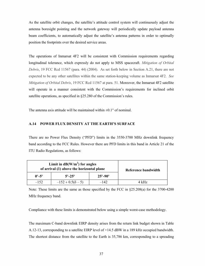
A.14 POWER FLUX DENSITY AT THE EARTH’S SURFACE
There are no Power Flux Density (“PFD”) limits in the 3550-3700 MHz downlink frequency
band according to the FCC Rules. However there are PFD limits in this band in Article 21 of the
ITU Radio Regulations, as follows:
Limit in dB(W/m2) for angles of arrival (δ) above the horizontal plane
0°-5° 5°-25° 25°-90° Reference bandwidth
–152 –152 + 0.5(δ – 5) –142 4 kHz
Note: These limits are the same as those specified by the FCC in §25.208(a) for the 3700-4200
MHz frequency band.
Compliance with these limits is demonstrated below using a simple worst-case methodology.
The maximum C-band downlink EIRP density arises from the return link budget shown in Table
A.12-13, corresponding to a satellite EIRP level of +14.5 dBW in a 189 kHz occupied bandwidth.
The shortest distance from the satellite to the Earth is 35,786 km, corresponding to a spreading
38
loss of 162.06 dB. Therefore the maximum possible PFD at the Earth’s surface would not exceed
14.5-162.06 = -147.6 dBW/m2/189kHz. In any 4 kHz band this would correspond to a maximum
PFD at the Earth’s surface measured in a 4 kHz band of -147.6 + 10log(4E3/189E3) = -164.3
dBW/m2/MHz. This is significantly less than the -152 dBW/m2/MHz PFD limit that applies at
elevation angles between 0° and 5°. Therefore compliance with the PFD limit is assured.
A.15 FREQUENCY TOLERANCE
The frequency translation accuracy is better than 1 part in 107, including periods of eclipse, over
the operational life of the spacecraft
A.16 CESSATION OF EMISSIONS
All communications link transmissions from the satellite can be turned on and off by ground
telecommand, thereby causing cessation of emissions from the satellite, as required.
A.17 TT&C
The telemetry, tracking, and command subsystem provides the satellite communications links for
pre-launch, orbit-raising, and on-station operations. The TT&C system receives commands from
the satellite mission control operations center, authenticates the commands, and distributes the
commands to the appropriate satellite control units. The TT&C system also transmits satellite
telemetry and receives and transmits ranging signals to the mission control operations center.
The TT&C system is a standard C-Band system, and incorporates redundant command receivers,
telemetry transmitters, and power amplifiers. The TT&C signals use the 6338 – 6342 MHz band
for commanding and the 3945 – 3955 MHz band for telemetry. The signals are received /
transmitted via a Global horn antenna in both polarizations. The TT&C earth station site for the
Inmarsat 4F2 satellite is located in Italy.
39
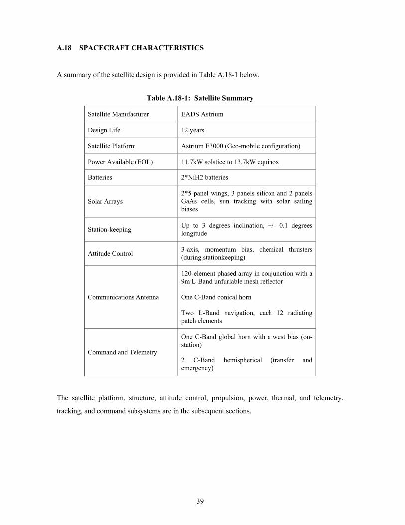
A.18 SPACECRAFT CHARACTERISTICS
A summary of the satellite design is provided in Table A.18-1 below.
Table A.18-1: Satellite Summary
Satellite Manufacturer EADS Astrium
Design Life 12 years
Satellite Platform Astrium E3000 (Geo-mobile configuration)
Power Available (EOL) 11.7kW solstice to 13.7kW equinox
Batteries 2*NiH2 batteries
Solar Arrays 2*5-panel wings, 3 panels silicon and 2 panels GaAs cells, sun tracking with solar sailing biases
Station-keeping Up to 3 degrees inclination, +/- 0.1 degrees longitude
Attitude Control 3-axis, momentum bias, chemical thrusters (during stationkeeping)
Communications Antenna
120-element phased array in conjunction with a 9m L-Band unfurlable mesh reflector
One C-Band conical horn
Two L-Band navigation, each 12 radiating patch elements
Command and Telemetry
One C-Band global horn with a west bias (on-station)
2 C-Band hemispherical (transfer and emergency)
The satellite platform, structure, attitude control, propulsion, power, thermal, and telemetry,
tracking, and command subsystems are in the subsequent sections.
40
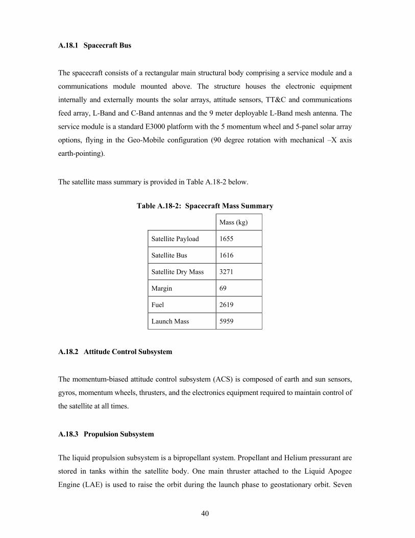
A.18.1 Spacecraft Bus
The spacecraft consists of a rectangular main structural body comprising a service module and a
communications module mounted above. The structure houses the electronic equipment
internally and externally mounts the solar arrays, attitude sensors, TT&C and communications
feed array, L-Band and C-Band antennas and the 9 meter deployable L-Band mesh antenna. The
service module is a standard E3000 platform with the 5 momentum wheel and 5-panel solar array
options, flying in the Geo-Mobile configuration (90 degree rotation with mechanical –X axis
earth-pointing).
The satellite mass summary is provided in Table A.18-2 below.
Table A.18-2: Spacecraft Mass Summary
Mass (kg)
Satellite Payload 1655
Satellite Bus 1616
Satellite Dry Mass 3271
Margin 69
Fuel 2619
Launch Mass 5959
A.18.2 Attitude Control Subsystem
The momentum-biased attitude control subsystem (ACS) is composed of earth and sun sensors,
gyros, momentum wheels, thrusters, and the electronics equipment required to maintain control of
the satellite at all times.
A.18.3 Propulsion Subsystem
The liquid propulsion subsystem is a bipropellant system. Propellant and Helium pressurant are
stored in tanks within the satellite body. One main thruster attached to the Liquid Apogee
Engine (LAE) is used to raise the orbit during the launch phase to geostationary orbit. Seven
41
ACS thrusters are mounted around the outside of the satellite. The thrusters provide the
impulse necessary for transfer orbit reorientation, 3-axis attitude control, East/West station-
keeping, station changes and disposal orbit maneuvers. In addition, the satellite has two plasma
thrusters using Xenon fuel for north-south station-keeping. The satellite has been designed to
perform a graveyard maneuver at end-of-life. This propulsion system is the standard design for
the Astrium E3000 series product line.
A.18.4 Electrical Power Subsystem
The electrical power subsystem is designed to provide more than 13 kW of power at the end of
life equinox. Power generation is accomplished by two (2) x five (5) panel solar arrays populated
with both silicon (Si) and gallium arsenide (GaAs) solar cells. The solar arrays track the sun
using two Solar Array Drives (SADs). Two rechargeable nickel hydrogen batteries are used to
store power for eclipse operations when the solar array is not illuminated. Power is supplied to
units via two non-redundant power buses. This power system is essentially the same as the
standard design for the Astrium E3000 product line.
Full details of the spacecraft’s electrical characteristics are provided in the Schedule S form.
A.18.5 Thermal Control Subsystem
The thermal control subsystem provides a controlled thermal environment throughout the
mission. The thermal control system consists of heat-pipes, surface treatments, radiators,
blankets, insulators, and heaters to maintain all the equipment within the required operating
environments. The service module thermal system is essentially the same as the standard design
for the Astrium E3000 product line system. The communications payload additionally uses heat
pipes.
A.18.6 Reliability
Payload reliability is 0.74 and bus reliability is 0.89 with an overall spacecraft reliability of
approximately 0.66. Amplifier and receiver sparing is consistent with documented failure rates
that allow the attainment of the overall spacecraft reliability numbers stated.
42
A.19 COMMUNICATIONS PAYLOAD
The communications payload includes all the necessary antennas and transponder hardware to
receive, amplify, configure and transmit signals among user terminals and satellite access
stations. The forward link provides communications between the gateway earth stations and the
user terminals using C-band on the uplink and L-Band on the downlink. The return link provides
communications between the user terminals and the gateway earth stations using L-Band on the
uplink and C-band on the downlink. Digital beam forming enables up to 256 L-Band beams to be
created; nominal configuration will have 1 global beam, 19 regional beams and on the order of
200 spot beams.
The Forward link receives signals at C-Band and transmits at L-Band. The signals are received by
a dual circular polarized horn in either LHCP or RHCP before being amplified in the C-Band
LNA. Each polarization is connected to the C-Band downconverter where the receive bandwidth
is divided into sub-bands prior to connecting to the DSP where the channel mapping and beam
forming functions take place on a channel by channel case. The DSP is followed by the L-Band
Post-processor where the signals are filtered and up converted to L-Band via 120 active paths in
the Post-processor one for each element of the Transmit Feed. To achieve the required output
power the Post-processor outputs are connected to Modular Power Amplifier’s, each comprising
an INET, input switch network, SSPA’s, output switch network and an ONET. The outputs of the
MPA’s are connected to 120 helix elements, which form the mobile antenna feed array to
transmit the signals via the antenna paraboloid reflector. The different beams are produced by
selected groups of helix elements illuminating the reflector as defined by the beam weights of the
DSP.
The Return link receives signals at L-Band and transmits at C-Band. The mobile receive antenna
operates in exactly the same way as the transmit antenna. The receive beams share a common
reflector and 120 feed elements with the transmit beams. Each element is connected to an LNA
where the signals are amplified before connecting to the L-Band Pre-processor. The Pre-
processor provides conversion of mobile receive signals to base band for processing within the
DSP; this includes beam forming multiplexing and channelization. The DSP is followed by the
C-Band Upconverter. The signals are up-converted and filtered within the C-Band Upconverter
before being amplified to the required transmit power in the C-Band MPA’s, one for the LHCP
and one for the RHCP. Each MPA comprises a C-Band Splitter, input switch network, High
43
Power Amplifier’s, output switch network and a Combiner. LHCP has an extra switch in the
switch networks so that one of the C-Band HPA’s can be in used in an emergency during the
LEOP to amplify the telemetry channel. The MPA’s are followed by output filters one on each
polarization before the signals are transmitted by the C-Band dual polarized horn.
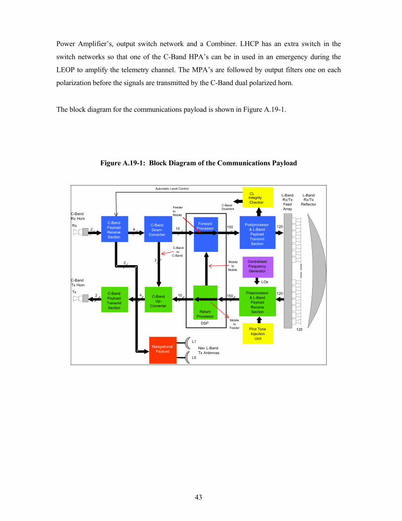
The block diagram for the communications payload is shown in Figure A.19-1.
Figure A.19-1: Block Diagram of the Communications Payload
C-Band Rx Horn Rx
L-Band Rx / Tx Feed Array
L-Band Rx / Tx
Reflector
120
C-Band PayloadReceiveSection
Mobileto
Feeder
FeedertoMobile
ForwardProcessor
Mobile to
Mobile
Postprocessor& L-BandPayloadTransmitSection
DSP
ReturnProcessor
C-BandUp-
Converter
C-BandDown-
Converter
NavigationalPayload
CentralisedFrequencyGenerator
LOs
CLIntegrityChecker
Pilot ToneInjection
Unit
C-BandDownlink
150
150C-Band PayloadTransmit Section
2
10
10
2
Automatic Level Control
2 120
120
C-Band Tx Horn Tx
4
2
C-Band to
C-Band
4 Preprocessor& L-BandPayloadReceiveSection
Nav L-Band Tx Antennas
L1
L5
44
A.20 TWO- DEGREE COMPATIBILITY ANALYSIS
With respect to the extended C-band (feeder links), there are no operational satellites within two
degrees using the bands. The nearest satellite using the extended C-bands is the INTELSAT-805
satellite at 55.5° W.L.; a nominal orbital separation of 2.75 degrees.
With respect to the conventional C-band (TT&C), the nearest satellite using the bands is the
INTELSAT-707 satellite at 53° W.L. Inmarsat and Intelsat have reached a frequency
coordination agreement for use of both the extended and conventional C-band frequencies.
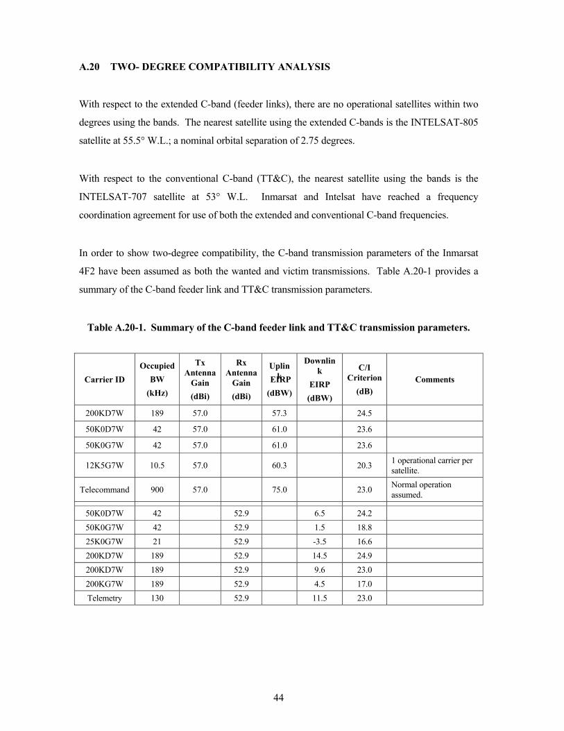
In order to show two-degree compatibility, the C-band transmission parameters of the Inmarsat
4F2 have been assumed as both the wanted and victim transmissions. Table A.20-1 provides a
summary of the C-band feeder link and TT&C transmission parameters.
Table A.20-1. Summary of the C-band feeder link and TT&C transmission parameters.
Carrier ID Occupied
BW (kHz)
Tx Antenna
Gain (dBi)
Rx Antenna
Gain (dBi)
Uplink EIRP
(dBW)
Downlink
EIRP (dBW)
C/I Criterion
(dB) Comments
200KD7W 189 57.0 57.3 24.5 50K0D7W 42 57.0 61.0 23.6 50K0G7W 42 57.0 61.0 23.6
12K5G7W 10.5 57.0 60.3 20.3 1 operational carrier per satellite.
Telecommand 900 57.0 75.0 23.0 Normal operation assumed.
50K0D7W 42 52.9 6.5 24.2 50K0G7W 42 52.9 1.5 18.8 25K0G7W 21 52.9 -3.5 16.6 200KD7W 189 52.9 14.5 24.9 200KD7W 189 52.9 9.6 23.0 200KG7W 189 52.9 4.5 17.0 Telemetry 130 52.9 11.5 23.0
45
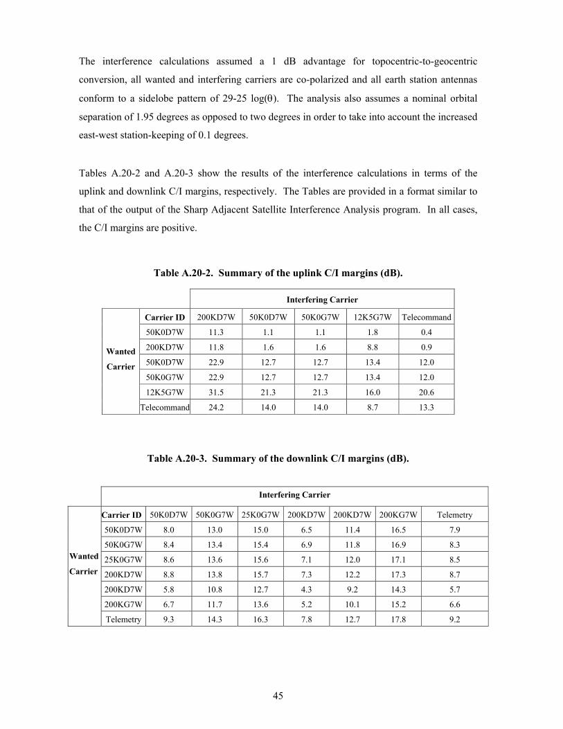
The interference calculations assumed a 1 dB advantage for topocentric-to-geocentric
conversion, all wanted and interfering carriers are co-polarized and all earth station antennas
conform to a sidelobe pattern of 29-25 log(θ). The analysis also assumes a nominal orbital
separation of 1.95 degrees as opposed to two degrees in order to take into account the increased
east-west station-keeping of 0.1 degrees.
Tables A.20-2 and A.20-3 show the results of the interference calculations in terms of the
uplink and downlink C/I margins, respectively. The Tables are provided in a format similar to
that of the output of the Sharp Adjacent Satellite Interference Analysis program. In all cases,
the C/I margins are positive.
Table A.20-2. Summary of the uplink C/I margins (dB).
Interfering Carrier
Carrier ID 200KD7W 50K0D7W 50K0G7W 12K5G7W Telecommand 50K0D7W 11.3 1.1 1.1 1.8 0.4
200KD7W 11.8 1.6 1.6 8.8 0.9
50K0D7W 22.9 12.7 12.7 13.4 12.0
50K0G7W 22.9 12.7 12.7 13.4 12.0
12K5G7W 31.5 21.3 21.3 16.0 20.6
Wanted
Carrier
Telecommand 24.2 14.0 14.0 8.7 13.3
Table A.20-3. Summary of the downlink C/I margins (dB).
Interfering Carrier
Carrier ID 50K0D7W 50K0G7W 25K0G7W 200KD7W 200KD7W 200KG7W Telemetry 50K0D7W 8.0 13.0 15.0 6.5 11.4 16.5 7.9
50K0G7W 8.4 13.4 15.4 6.9 11.8 16.9 8.3
25K0G7W 8.6 13.6 15.6 7.1 12.0 17.1 8.5
200KD7W 8.8 13.8 15.7 7.3 12.2 17.3 8.7
200KD7W 5.8 10.8 12.7 4.3 9.2 14.3 5.7
200KG7W 6.7 11.7 13.6 5.2 10.1 15.2 6.6
Wanted
Carrier
Telemetry 9.3 14.3 16.3 7.8 12.7 17.8 9.2
46
A.21 ORBITAL DEBRIS MITIGATION
Inmarsat will utilize a satellite and launch vehicle design that minimizes the amount of debris
released during normal operations. Inmarsat and its satellite contractor have performed a careful
assessment, and can confirm that no debris will be released by the space station during normal
on-station operations. As noted below, Inmarsat has taken measures to ensure a safe operational
configuration of its satellite system through hardware design and operational procedures. Each
section below addresses specific measures taken by Inmarsat, as required under §25.114(d)(14) of
the Commission’s rules, to limit the possibility that its space station operations will generate
orbital debris.
Collisions with small debris, meteoroids: Inmarsat has assessed the probability of the space
station becoming a source of debris by collisions with small debris or meteoroids that could cause
loss of control and prevent post-mission disposal. Collisions with the background environment,
including meteoroids, are considered as part of the satellite design. These effects are considered
on a statistical basis to determine collision risk. Inmarsat’ satellite manufacturer, Astrium,
includes meteoroid environments as part of the satellite Environmental Requirement
Specifications. Literature is reviewed for large size space objects, particularly technical papers
that present collision probability estimates for orbital conditions of interest. The satellite
requirement was derived from these technical papers as well as NASA models to include debris
and meteoroids of various sizes. Inmarsat has taken steps to limit the effects of such collisions
through shielding, the placement of components, and the use of redundant systems.
Accidental explosions, energy sources on board: Inmarsat has assessed and limited the
probability of accidental explosions during and after completion of mission operations. In
designing the Inmarsat 4F2 satellite, the satellite manufacturer has taken steps to ensure that
debris generation will not result from the conversion of energy sources on board the satellite into
energy that fragments the satellite. In particular, the satellite manufacturer advises that no
structural failures of pressurized volumes have occurred on its satellites to date. Burst tests are
performed on all pressure vessels during qualification testing to demonstrate a margin of safety
against burst. Bipropellant mixing is prevented by the use of valves that prevent backwards flow
in propellant lines and pressurization lines. Although NiH2 batteries retain fluids in a pressure
vessel, pressure at end-of-life is maintained at a low level, and procedures will be undertaken by
47
Inmarsat to assure that the battery does not retain a charge at the end of the mission. Pyrotechnics
are nominally only used in the mission as part of the initial deployment process. After orbit
raising to the disposal orbit, all unfired pyrotechnics will be fired as part of the final satellite
decommission. Upon reaching the final disposal orbit, all fuel tanks will be close to empty. All
propellants will be vented utilizing the on-board thrusters.
Collisions with large debris or operational space stations: Inmarsat has assessed and limited
the probability of the space station becoming a source of debris by collisions with large debris or
other operational space stations. Specifically Inmarsat has assessed the possibility of collision
with satellites located at, or reasonably expected to be located at, the requested orbital location, or
assigned in the vicinity of that location.
Inmarsat has examined whether its station-keeping volume might overlap with that of other
operational or planned satellites in the vicinity of the 52.75° W.L. orbital location. In considering
operational and planned satellites that may have a station-keeping volume that overlaps the
Inmarsat 4F2 satellite, Inmarsat reviewed the lists of FCC licensed systems and systems that are
currently under consideration by the FCC. In addition, networks for which a request for
coordination has been submitted to the ITU for an orbital location between 52.55° W.L. and 53°
W.L. have also been reviewed.
Based on the review, Intelsat has Commission authorization to operate the INTELSAT-707
satellite at 53° W.L. There are no networks currently under consideration by the Commission to
use the 53° W.L. slot.
The only published ITU networks between 52.55° W.L. and 53° W.L. are Intelsat networks (U.S.
and U.K.) at 53° W.L. and a U.S. Ku/V-band network at 53° W.L. that is not assigned to any U.S.
operator. The operation of the Inmarsat 4F2 satellite at the 52.75° W.L. position avoids the
possibility of an in-orbit collision by separating Inmarsat 4F2’s station-keeping box from that of
Intelsat’s.
Inmarsat has selected one of the established launch agencies with a proven record of safe flight
planning, taking care to minimize the possibilities of any collision. The launch contractor is
responsible for collision avoidance maneuvers and launch analysis of in-flight profile planning
48
for the launch vehicle. Inmarsat uses the services of the USSTRATCOM organization to perform
collision avoidance analysis for the Inmarsat 4F2 satellite for the post-launch phase
Post-mission disposal plans (disposal altitude and calculations, fuel reserves): At the end of
the operational life of the Inmarsat 4F2 satellite, Inmarsat plans to maneuver the satellite to a
disposal orbit with a minimum perigee of 337 km above the normal GSO operational orbit. This
proposed disposal orbit altitude is based on the following calculation, as required in §25.283:
Solar array area = 90 m2
Satellite body area (oriented for max antenna exposure) = 17.4m2
L-band antenna area = 32 m2
C-band antenna area = 32 m2
Total Solar Pressure Area “A” = 171.4 m2
“M” = Dry Mass of Satellite = 3340 kg
“CR” = Solar Pressure Radiation Coefficient (worst case) = 2.0
Therefore the Minimum Disposal Orbit Perigee Altitude:
= 36,021 km + 1000 x CR x A/m
= 36,021 km + 1000 x 2 x 171.4/3340
= 36,123.6
= 337 km above GSO (35,786 km)
The propulsion subsystem design and the satellite fuel budget account for the post-mission
disposal of the satellite. 15.6 kg of propellant is expected to be allocated and reserved for the
final orbit raising maneuvers.
A.22 COMMENTS CONCERNING SCHEDULE S SUBMISSION
In this section, additional explanation is provided concerning specific areas of the Schedule S
form where the advanced design of the Inmarsat 4F2 satellite design does not necessarily
comport well with the mechanics of the Schedule S form. To the extent that the Commission
49
considers any of these areas to be in non-compliance with the Schedule S requirements, the
applicant requests a waiver, based on the justification and explanation given below.
1. S7 and S8 (“Antenna Beam” and “Beam Diagram tabs in Schedule S):
(i) Only one representative uplink and downlink L-band spot beam (LSU and
LSD beam) and one representative uplink and downlink L-band regional
beam (LRU and LRD beam) has been included in the Schedule S form. The
use of a phased array antenna provides complete flexibility in the generation
of the spot and regional beams and therefore there are an infinite number of
pointing directions for the spot and regional beams. A single representative
beam for each of the beams LSU, LSD, LRU and LRD has been included in
the Schedule S form. Should the Commission require it, Inmarsat will
provide additional gain contour files for other example beam positions over
the U.S.
(ii) Item S7m: Transmit Max EIRP (dBW) for the “LSD” and “LRD” beams.
The values entered here are 70 and 58 dBW, respectively, and are the
aggregate EIRP values for the two beam types. In practice, for each beam
type, the available power will be distributed across a number of the beams
within that beam type.
2. S10 (“Space Station Transponders” tab in Schedule S):
The satellite does not have conventional transponders. There is no fixed frequency
relationship between the L-band frequencies and the extended C-band feeder link
frequencies. For purposes of completing the Schedule S form, the connectivity between
the feeder link C-band spectrum and L-band spectrum, in both the forward and return
directions, have been described as showing all available feeder link spectrum strapped
to the available L-band spectrum.
___________________________________
50
CERTIFICATION OF PERSON RESPONSIBLE FOR PREPARING ENGINEERING INFORMATION
I hereby certify that I am the technically qualified person responsible for preparation of
the engineering information contained in this pleading, that I am familiar with Part 25 of the
Commission’s rules that I have either prepared or reviewed the engineering information
submitted in this pleading, and that it is complete and accurate to the best of my knowledge and
belief.
/s/
¯¯¯¯¯¯¯¯¯¯¯¯¯¯¯¯¯¯
Stephen D. McNeil
Telecomm Strategies, Inc.
6404 Highland Drive
Chevy Chase, MD 20815
(301) 656-8969
Recommended