A BestPracticesSteamTechnicalBrief
IndustrialSteam SystemProcess-ControlSchemes
U.S. Department of EnergyEnergy Efficiency and Renewable EnergyBringing you a prosperous future where energy is clean, abundant, reliable, and affordable
Energy efficiency and clean, renewable energy will mean a stronger economy, a cleaner environment, and greater energyindependence for America. By investing in technology breakthroughs today, our nation can look forward to a more resilient economy and secure future.
Far-reaching technology changes will be essential to America’senergy future. Working with a wide array of state, community,industry, and university partners, the U.S. Department of Energy’sOffice of Energy Efficiency and Renewable Energy invests in adiverse portfolio of energy technologies that will:
• Conserve energy in the residential, commercial, industrial, government, and transportation sectors
• Increase and diversify energy supply, with a focus on renewable domestic sources
• Upgrade our national energy infrastructure• Facilitate the emergence of hydrogen technologies
as a vital new “energy carrier.”
The Opportunities
Biomass ProgramUsing domestic, plant-derived resources to meet our fuel, power,and chemical needs
Building Technologies ProgramHomes, schools, and businesses that use less energy, cost less tooperate, and ultimately, generate as much power as they use
Distributed Energy & Electric Reliability ProgramA more reliable energy infrastructure and reduced need for newpower plants
Federal Energy Management ProgramLeading by example, saving energy and taxpayer dollars in federalfacilities
FreedomCAR & Vehicle Technologies ProgramLess dependence on foreign oil, and eventual transition to an emisions-free, petroleum-free vehicle
Geothermal Technologies ProgramTapping the earth’s energy to meet our heat and power needs
Hydrogen, Fuel Cells & Infrastructure Technologies ProgramPaving the way toward a hydrogen economy and net-zero carbonenergy future
Industrial Technologies ProgramBoosting the productivity and competitiveness of U.S. industrythrough improvements in energy and environmental performance
Solar Energy Technology ProgramUtilizing the sun’s natural energy to generate electricity and providewater and space heating
Weatherization & Intergovernmental ProgramAccelerating the use of today’s best energy-efficient and renewabletechnologies in homes, communities, and businesses
Wind & Hydropower Technologies ProgramHarnessing America’s abundant natural resources for clean powergeneration
To learn more, visit www.eere.energy.gov
FOR ADDITIONAL INFORMATION,PLEASE CONTACT:
DOE Information ClearinghousePhone: (800) 862-2086Fax: (360) [email protected]
Visit our home page atwww.oit.doe.gov
Please send any comments,questions, or suggestions [email protected]
Industrial Technologies ProgramEnergy Efficiency and Renewable EnergyU.S. Department of EnergyWashington, DC 20585-0121
Industrial Technologies Program
DOE/GO-102003-1737July 2003
Boosting the productivity and competitiveness of U.S. industry through improvements in energy and environmental performanceA STRONG ENERGY PORTFOLIO FOR A STRONG AMERICA
ACKNOWLEDGEMENTS:
The Industrial Technologies Programwould like to thank Plant Support &Evaluations, Inc., for writing thisBestPractices Steam Technical Brief, and the BestPractices Steam technicalsubcommittee for reviewing thepublication.

Industrial Steam System Process-Control Schemes
1
Industrial Steam SystemProcess-Control Schemes
This BestPractices Steam Technical Brief was developed to provide a basic understanding of thedifferent process-control schemes used in a typical steam system. This brief provides a fundamentaloverview, and the reader should be aware that more in-depth knowledge is required to achieve thebest process-control results.
This brief will cover the following process-control schemes:
• Feedback• Feed-forward• Backpressure • Ratio• Cascade• Differential.
The above control schemes can be applied to the following generic applications:
• Temperature• Flow • Level• Pressure.
A control system will use one or more of the above schemes to achieve process control. The various control schemes are detailed in the typical application examples defined in this brief.
In any control scheme that is applied, the user must define three elements for the controlprocess:
• Process Variable (Sensing device)– Flow transmitter– Level transmitter– Pressure transmitter– Differential transmitter– Temperature transmitter
• Controller– Self-contained– Proportional and integral (PI)– Proportional, integral, derivative (PID)
• Output control signal (Final controlling mechanism)– Control valve– Actuator– Another device.
This review focuses on control valves, which are generally used as the final element. The controlvalve has several classifications:
• Regulating design valve– Self contained– External pilot operated
• Pneumatic actuated valve– Globe design– Caged trim– Ball.

Industrial Steam System Process-Control Schemes
In any process-control selection, understanding the advantages and disadvantages of each selection is important.
The regulating control valve, or regulator, is a device that has a 20 to 1 turndown and limitedselections of flow-trim characteristics.
The globe-style control valve has 30 to 1 turndown and is a device that can provide a limitednumber of selections of flow-trim characteristics. Flow-trim characteristics can be linear, non-linear,or modified equal percentage. Flow-trim selection can enhance control of steam flow at varying loaddemands.
The cage-trim control valve is the most flexible and may be the most commonly used for precisesteam process control. This valve provides the largest selection of different flow-trim characteristics,and the highest turndown capabilities, with a 40 to 1 turndown.
The ball valve has a number of different flow characteristics. The flow profile can be changed bythe design of the ball (for example, standard, V-ball, etc.). The ball-valve turndown can be as high as25 to 1.
• Turndown summary:– Regulating valve: 20 to 1– Globe style valve: 30 to 1– Cage trim valve: 40 to 1– Ball valve (with special trim): 25 to 1
Symbol Definitions
CS = CascadeCT = ControllerFT = Flow transmitterPT = Pressure transmitterPV = Process VariableR = RatioSP = Set PointTT = Temperature transmitter
Feedback Control
One of the simplest process-control schemes that steam applications use is the feedback-controlscheme (Figure 1). The advantage of this control scheme is that it is simple; however, it depends on asingle transmitter sensing a change in flow, pressure, or level to provide the feedback response to thecontroller or valve. This control scheme does not take into consideration any of the other variablesin the process.
2
CT
PT
Figure 1: Feedback Control

Industrial Steam System Process-Control Schemes
Feedback Control (Backpressure application)
Feedback control for a steam-system backpressure-control scheme utilizes another parameter toprovide the controller with information on process changes (Figure 2). Backpressure control is used tomaintain inlet-steam pressure above a predetermined setpoint. Pressure transmitters are located on theinlet and outlet piping, which will notify the controller that changes are occurring. Consequently, backpressure control work in conjunction with feedback control. The most common application for asteam system is the elimination of instant, high demand for steam from a process that will affect theboiler operation.
Feed-Forward Control
Feed-forward control uses a secondary input from another variable to assist or provide the controller with the knowledge that various changes are occurring in the process (Figure 3). Steamflow measurement in pressure-reducing applications adds instant identification that a change isoccurring. This allows the controller to make corrective actions before a significant temperature orsteam-pressure change has occurred. Consequently, feed-forward control is used in conjunction withfeedback control. The feedback loop is used to maintain setpoint control, and feed forward is used tocompensate for any errors and unmeasured disturbances. One of the most common applications is apressure transmitter that is used on a shell-and-tube heat exchanger to sense and feed-forward achange in steam pressure on the shell (steam side). The steam pressure change on the shell side is thefirst indication that the temperature, or process variable, will change in a short period of time.
3
CT
PTPT
Figure 2: Feedback for a Back-Pressure Application
CT
PT
Figure 3: Feed-Forward Control
T

Industrial Steam System Process-Control Schemes
4
Ratio Control
Ratio control is a duplex form of feedback control that has two sets of variables, for which thecontroller calculates a setpoint from the two variables for the control scheme (Figure 4). The object ofa ratio-control scheme is to keep the ratio of two variables at different values, depending on the final objective of the control system.
As Figure 4 indicates, on a pressure-control system the control output to the different valves is aratio that depends on the percentage of travel, 0 to 100%, and the pressure transmitter. This type ofcontrol scheme is applied when two or more control valves occur in a pressure-reducing application.
Cascade Control
Cascade control is widely used within steam-process industries (Figure 5). The conventional cascade scheme has two distinct functions with two control loops. Cascade control is used toimprove the response of the single-feedback strategy. A heat exchanger that varies process flow willhave different steam requirements depending on the flow. Cascade control “understands” therequirements and adjusts the output to the control valve according to process flow. The main objective is to achieve the desire output temperature of the process, which is the lead process variable. The idea is similar to that of the feed-forward control scheme.
CT
RPT
Figure 4: Ratio Control
CT
TTFT
Figure 5: Cascade Control
Process flow toa heat
exchanger
Temperatureoutput

Industrial Steam System Process-Control Schemes
5
Differential Control
Differential control is typically used on rotating-cylinder dryers because differential pressure isrequired across the siphoning joint to assist in evacuating the condensate (Figure 6). The use of rotating cylinders is the only instance where gravity drainage of condensate is not possible from theprocess. Therefore, using differential control identifies the parameters of inlet (P1) and outlet (P2)process pressures and maintains a lower outlet steam pressure (P1>P2), thus achieving the differential.Other gravity-limited heat-transfer applications will use differential control for condensate evacuation.
Control Actions
The controller’s output to the final control element, the valve or actuator, is accomplished in different ways:
• On/off– Simplest– Least accurate
• PI (Proportional and integral)– Medium cost factor– Medium accuracy
• PID (Proportional, integral and derivative)– Highest cost– Highest accuracy.
On/Off Control
Control schemes using a feedback control parameter can use on/off control. On/off control is thesimplest control scheme with the highest degree of inaccuracy. The controller has a set point withhigh- and low-control action points, similar to a home air conditioning or heating system. The thermostat has a desired setpoint (SP) and the system is actually operated between two temperaturepoints: on/off. The desired outlet temperature is 180°F (SP) and the on/off control activates the steamvalve to heat the product to 185°F. At 185°F, the steam valve deactivates and this allows the processto cool down to 175°F, a lower set point. The steam is activated and deactivated between the highand low process setpoints.
Proportional and Integral (PI) Control
PI control uses an algorithm that is proportional to the difference between a setpoint (SP) and aprocess variable (PV), and integral time-function algorithms, which provide a continuous-controlprocess output to meet the desired setpoint. This is similar to a residential light dimmer switch versusan on/off light switch. The dimmer mechanism provides a light variable from off to full brightness,or anywhere in between. PI controls the steam flow from zero to full flow, or anywhere in between,on a continuous basis.
CT
Figure 6: Differential Control
PTPT

Industrial Steam System Process-Control Schemes
Proportional, Integral, and Derivative (PID) Control
PID control has proportional, integral, and derivative algorithms available to maintain the setpoint of the process. Steam applications use the proportional and integral part of “PID;”the derivative algorithm is seldom used, and then only by experts who are experienced in control algorithms. If the heat-transfer equipment, control valve, and the controller are properly selected,then proportional and integral are the only parameters required to maintain a highly accurate processresult.
Applications of Control Schemes
Steam Pressure Control
The majority of industrial steam systems will have a pressure-reducing valve application. High-pressure steam is reduced to lower-pressure steam for a process or heating application. Usedthroughout all types of industries, some plants will have from one to more than one hundred different pressure-control valves. The feedback control scheme is simply a pressure transmitter and acontroller, or a sensing line coming back to a pilot on a valve.
In a simple regulator-type control system for pressure control, a sensing line is providing thefeedback to the external pilot, which is the controlling device (Figure 7). The main valve is the finalcontrolling element.
A control-valve layout uses a pressure transmitter as the feedback-sensing device with the controller providing the correct control action (Figure 8). The pneumatic valve is the final controlling element.
6
Figure 7: Regulating Valve Using a Feedback-Control Scheme
Figure 8: Controller Using Feedback To Control a Valve
20 PIPE DIAMETER
CONTROLLER
PRESSURETRANSMITTER

Industrial Steam System Process-Control Schemes
7
Many applications require the use of one or more valves to achieve the necessary turndown.Control valves that are used in any type of control scheme should utilize a secondary pressure dropif the control valve is in a sub-critical flow operation. Figure 9 shows the use of a simple orifice plate,placed after the control valve, to provide a secondary pressure drop. This type of installation hasbeen used for more than 60 years. The inlet pressure to the control valve is P1, the pressure betweenthe control valve and the orifice is P2, and the final control point or outlet pressure to the controlvalve is P3. Orifice plates, when properly sized and installed, prevent the valve from operating at asub-critical flow and causing premature failure.
Backpressure Control
The backpressure control is a type of feedback-control scheme (Figure 10), typically used onsmaller boilers without large steam reservoir capabilities for instant steam load demands. High instantaneous demands for steam can cause unwanted shutdowns of the boiler. Using backpressurecontrol prevents the shutdown. A transmitter sensing the inlet pressure to the valve identifies areduction of pressure beyond the predetermined set point, and the valve begins to close down tomaintain the steam set-pressure on the inlet of the valve. This action overrides any pressure requirements or needs on the downstream side of the valve.
Figure 9: Feedback Control with Muffling Orifice
CONTROLLER
18” MIN.
3” MIN.
MUFFLINGORIFICE
PRESSURETRANSMITTER
P3P2
P1
Figure 10: Backpressure Control
CONTROLLER
PRESSURETRANSMITTER
PRESSURETRANSMITTER

Feedforward Control
Figure 11 shows a feedforward/feedback control system. The orifice steam flow meter is provid-ing the feedforward information to the controller. The pressure transmitter is providing the feedbackto the controller. The pneumatic control valve is the final element.
Ratio Control
Another way to accomplish the goal of meeting large steam-flow requirements is the use of multiple valves (Figure 12). Multiple valves can provide better control in meeting the process requirements. In a two-stage pressure-control scheme, the stages use a feedback-control scheme andthen ratio the controller output to the valves. As shown in Figure 12, the system is the ratio or position of the primary and secondary valve depending on the required flow rates. Parallel positioningvalves are quite commonly used in process-heating applications where load conditions vary greatlyfrom the coldest part of the season to the warmest part of the season.
Industrial Steam System Process-Control Schemes
8Figure 12: Ratio Control
CONTROLLER
ORIFICE PLATE
ORIFICE PLATE
20 PIPE DIAMETER
20 PIPE DIAMETER
PRESSURETRANSMITTER
Figure 11: Feedforward/Feedback Control
CONTROLLER
PRESSURETRANSMITTER
ORIFICEPLATE
PRESSURETRANSMITTER
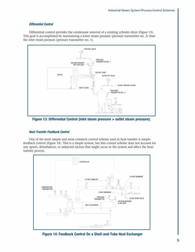
Differential Control
Differential control provides the condensate removal of a rotating cylinder dryer (Figure 13). This goal is accomplished by maintaining a lower steam pressure (pressure transmitter no. 2) thanthe inlet steam pressure (pressure transmitter no. 1).
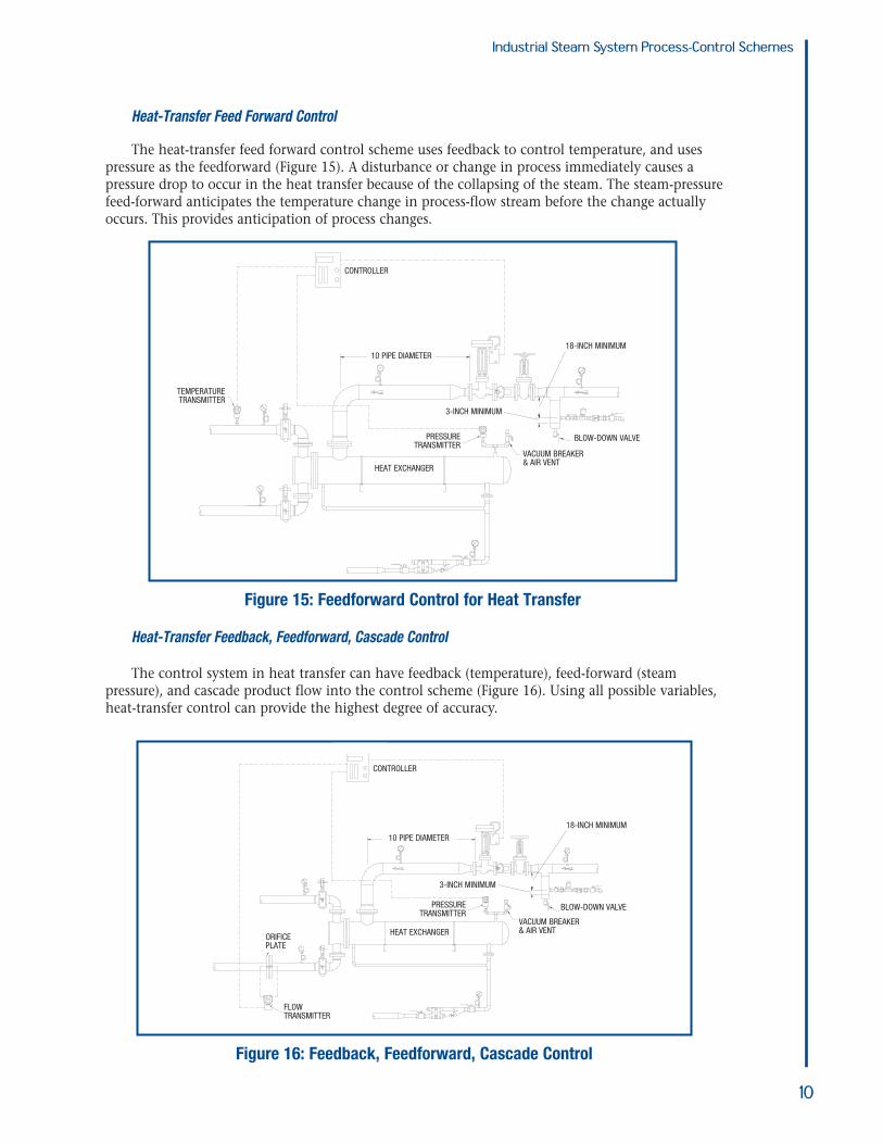
Heat-Transfer Feedback Control
One of the most simple and most common control scheme used in heat transfer is simple-feedback control (Figure 14). This is a simple system, but this control scheme does not account forany upsets, disturbances, or unknown factors that might occur in the system and affect the heat-transfer process.
Industrial Steam System Process-Control Schemes
9
Figure 13: Differential Control (Inlet steam pressure > outlet steam pressure).
CONTROL VALVE
BLOW-THROUGH STEAM
ROTARY JOINT
BLOW-OFF VALVE
SIGHT GLASS
PRESSURETRANSMITTER NO. 1
PRESSURETRANSMITTER NO. 2
VACUUM BREAKERWITH AIR VENT
DRYER
Figure 14: Feedback Control On a Shell-and-Tube Heat Exchanger
BLOW DOWN VALVE
3-INCH MINIMUM
VACUUM BREAKER& AIR VENT
HEAT EXCHANGER
TEMPERATURETRANSMITTER
PRESSURETRANSMITTER
CONTROLLER
18-INCH MINIMUM
10 PIPE DIAMETER
Industrial Steam System Process-Control Schemes
Heat-Transfer Feed Forward Control
The heat-transfer feed forward control scheme uses feedback to control temperature, and usespressure as the feedforward (Figure 15). A disturbance or change in process immediately causes apressure drop to occur in the heat transfer because of the collapsing of the steam. The steam-pressurefeed-forward anticipates the temperature change in process-flow stream before the change actuallyoccurs. This provides anticipation of process changes.
Heat-Transfer Feedback, Feedforward, Cascade Control
The control system in heat transfer can have feedback (temperature), feed-forward (steam pressure), and cascade product flow into the control scheme (Figure 16). Using all possible variables,heat-transfer control can provide the highest degree of accuracy.
10
Figure 16: Feedback, Feedforward, Cascade Control
CONTROLLER
18-INCH MINIMUM
3-INCH MINIMUM
BLOW-DOWN VALVE
FLOWTRANSMITTER
ORIFICEPLATE
PRESSURETRANSMITTER
VACUUM BREAKER& AIR VENT
10 PIPE DIAMETER
HEAT EXCHANGER
Figure 15: Feedforward Control for Heat Transfer
CONTROLLER
10 PIPE DIAMETER
TEMPERATURETRANSMITTER
PRESSURETRANSMITTER
HEAT EXCHANGER
BLOW-DOWN VALVE
VACUUM BREAKER& AIR VENT
3-INCH MINIMUM
18-INCH MINIMUM

Feedback-Condensate ControlA condensate feedback-control scheme is used in condensate removal and is typically a simple-
level transmitter, controller, and control valve (Figure 17). This system is typically used on a heattransfer application.
In process-flow operations where condensate flow rates are 8,000 pounds per hour (lbs/h) orhigher, steam traps are not advised. Instead, use a level transmitter, controller, and control valve witha feedback-control scheme. This feedback-control scheme gives you the ability to remove the condensate from the heat-transfer process on a continuous basis. In these high-flow rates, a controlvalve provides a high degree of accuracy and control in the removal of condensate from heat transfer.
Control Versus Cost
The best process-control scheme is one that provides the system with the most information possible; to do this, the user must evaluate cost factor. The more information that is provided to thecontrol scheme, the higher the cost for the field devices—and the more complex the controller, control strategy, and wiring. Therefore, the user must consider cost justification to identify the correct control scheme for the process application.
Conclusions and Recommendations
Control strategies, when evaluated from basic inputs and outputs, are simple and straightforward.Control schemes should be determined based on the level of control necessary, the cost, and theprocess.
When determining control-scheme selection:
• Outline objectives and goals clearly before starting the selection process• Select the correct control scheme for the process• Select the proper equipment for the application.
Industrial Steam System Process-Control Schemes
11
Figure 17: Feedback-Condensate Control
CONTROLLER
CONTROLLER
18-INCH MINIMUM
3-INCH MINIMUM
BLOW-DOWN VALVEPRESSURETRANSMITTER
TEMPERATURETRANSMITTER
VACUUM BREAKER& AIR VENT
10 PIPE DIAMETER
HEAT EXCHANGER

A BestPracticesSteamTechnicalBrief
IndustrialSteam SystemProcess-ControlSchemes
U.S. Department of EnergyEnergy Efficiency and Renewable EnergyBringing you a prosperous future where energy is clean, abundant, reliable, and affordable
Energy efficiency and clean, renewable energy will mean a stronger economy, a cleaner environment, and greater energyindependence for America. By investing in technology breakthroughs today, our nation can look forward to a more resilient economy and secure future.
Far-reaching technology changes will be essential to America’senergy future. Working with a wide array of state, community,industry, and university partners, the U.S. Department of Energy’sOffice of Energy Efficiency and Renewable Energy invests in adiverse portfolio of energy technologies that will:
• Conserve energy in the residential, commercial, industrial, government, and transportation sectors
• Increase and diversify energy supply, with a focus on renewable domestic sources
• Upgrade our national energy infrastructure• Facilitate the emergence of hydrogen technologies
as a vital new “energy carrier.”
The Opportunities
Biomass ProgramUsing domestic, plant-derived resources to meet our fuel, power,and chemical needs
Building Technologies ProgramHomes, schools, and businesses that use less energy, cost less tooperate, and ultimately, generate as much power as they use
Distributed Energy & Electric Reliability ProgramA more reliable energy infrastructure and reduced need for newpower plants
Federal Energy Management ProgramLeading by example, saving energy and taxpayer dollars in federalfacilities
FreedomCAR & Vehicle Technologies ProgramLess dependence on foreign oil, and eventual transition to an emisions-free, petroleum-free vehicle
Geothermal Technologies ProgramTapping the earth’s energy to meet our heat and power needs
Hydrogen, Fuel Cells & Infrastructure Technologies ProgramPaving the way toward a hydrogen economy and net-zero carbonenergy future
Industrial Technologies ProgramBoosting the productivity and competitiveness of U.S. industrythrough improvements in energy and environmental performance
Solar Energy Technology ProgramUtilizing the sun’s natural energy to generate electricity and providewater and space heating
Weatherization & Intergovernmental ProgramAccelerating the use of today’s best energy-efficient and renewabletechnologies in homes, communities, and businesses
Wind & Hydropower Technologies ProgramHarnessing America’s abundant natural resources for clean powergeneration
To learn more, visit www.eere.energy.gov
FOR ADDITIONAL INFORMATION,PLEASE CONTACT:
DOE Information ClearinghousePhone: (800) 862-2086Fax: (360) [email protected]
Visit our home page atwww.oit.doe.gov
Please send any comments,questions, or suggestions [email protected]
Industrial Technologies ProgramEnergy Efficiency and Renewable EnergyU.S. Department of EnergyWashington, DC 20585-0121
Industrial Technologies Program
DOE/GO-102003-1737July 2003
Boosting the productivity and competitiveness of U.S. industry through improvements in energy and environmental performanceA STRONG ENERGY PORTFOLIO FOR A STRONG AMERICA
ACKNOWLEDGEMENTS:
The Industrial Technologies Programwould like to thank Plant Support &Evaluations, Inc., for writing thisBestPractices Steam Technical Brief, and the BestPractices Steam technicalsubcommittee for reviewing thepublication.
Recommended