XD INDEXERXD INDEXERReference Manual
SAC-XD-01k
ORMEC Systems Corp, 19 Linden Park, Rochester, NY 14625 Phone: (585) 385-3520, www.ormec.com

Indexer Reference Manual
Copyright NoticeCopyright © 2009-2013 by ORMEC Systems Corp. All rights reserved. This manual and any software that it may describe, remain the exclusive property of ORMEC Systems Corp. No part of either may be reproduced in any form without the prior written permission of ORMEC.
Trademark NoticeMotionSetTM is a trademark of ORMEC Systems Corporation.
ORMEC® is a registered trademark of ORMEC Systems Corporation.
WarrantyORMEC extends no warranty with respect to the merchantability or fitness of this product for any particular purpose. It is the customer’s responsibility to determine whether it is suitable for the specific application and whether it meets performance, reliability and safety requirements when used in that application. ORMEC reserves the right to make improvements to the product as well as this documentation at any time without notice.
Terms and ConditionsAll hardware and software sold or otherwise provided by ORMEC is made available subject to ORMEC's published Standard Terms and Conditions of Sale.
2 2013-05-17
Indexer Reference Manual Table of Contents
Table of ContentsTable of Contents.......................................................................................................................3List of Tables..............................................................................................................................5List of Figures............................................................................................................................7Introduction ..............................................................................................................................9Using this Reference Guide ......................................................................................................9Safety First ..............................................................................................................................10
Safety Precautions .......................................................................................................................................10Qualified Personnel ......................................................................................................................................10Mount in an Enclosure ...................................................................................................................................10Drive Settings ...............................................................................................................................................10Grounding .....................................................................................................................................................10Hot surfaces present .......................................................................................................................................11Don't disconnect while live ...........................................................................................................................11Residual Voltages ...........................................................................................................................................11Keep Covers on .............................................................................................................................................11
Indexer Features......................................................................................................................13Motion Features...............................................................................................................................................13Communication...............................................................................................................................................13Motor Feedback ..............................................................................................................................................14Auxiliary Feedback Interface .........................................................................................................................14Built in I/O......................................................................................................................................................14Power connections...........................................................................................................................................15Displays and Troubleshooting made simple....................................................................................................15Advanced Features..........................................................................................................................................15System Definition and Start up Simplified......................................................................................................16Certifications and safety markings...................................................................................................................16Overview and Training Videos........................................................................................................................18
Implementation Guidelines ..................................................................................................20Read the safety precautions ..........................................................................................................................20Read the manual ...........................................................................................................................................20Grounding for return currents ........................................................................................................................20Separate motor cables ...................................................................................................................................20Use shielded motor cables ............................................................................................................................20Fuses and line filters ......................................................................................................................................21Mount for cooling .........................................................................................................................................21Use sufficient wires ......................................................................................................................................21
Decoding Model Numbers ....................................................................................................22Quickstart................................................................................................................................23
Quickstart Overview .......................................................................................................................................23Step Q 1: Connect to the Indexer ....................................................................................................................25
Power In.........................................................................................................................................................................25Motor Connections ........................................................................................................................................................26Commissioning Software (GUI) Connections ..............................................................................................................26
Step Q 2: Defining Indexer actions .................................................................................................................26Step Q 3: Configure the Indexer .....................................................................................................................27
3 2013-05-17
Indexer Reference Manual Table of Contents
Turn Power On ..............................................................................................................................................................27Configure the Indexer ...................................................................................................................................................28
Step Q 3: Move the motor ..............................................................................................................................28Connecting to the Indexer ......................................................................................................30
Step C 1: Mounting the Indexer ......................................................................................................................30Step C 2: Connection Overview .....................................................................................................................33Step C 2: Provide control power .....................................................................................................................37
AC control power ..........................................................................................................................................................37DC control power ..........................................................................................................................................................39
Step C 3: Provide motor power – input ..........................................................................................................39Step C 4: Connect motor power – output .......................................................................................................41Step C 5: Connect motor feedback ................................................................................................................43
Quadrature Encoders......................................................................................................................................................43Yaskawa Serial Encoders ..............................................................................................................................................44EnDat Serial Encoders ..................................................................................................................................................45
Step C 6: Enable the Indexer ..........................................................................................................................46Hardware enable............................................................................................................................................................46MotionSet - Software enable..........................................................................................................................................47
Step C 7: Connecting I/O points .....................................................................................................................47Inputs: ...........................................................................................................................................................................47Outputs: .......................................................................................................................................................................52I/O Functionality............................................................................................................................................................56
Step C 8: Connecting Safety Circuit ...............................................................................................................59Defining Motions & Projects..................................................................................................60
Step D 1: Open commissioning tool – MotionSet ...........................................................................................60Step D 2: Start your project ............................................................................................................................60Step D 3: Select your drive .............................................................................................................................61Step D 4: Select your motor ............................................................................................................................63Step D 6: Set motor tuning .............................................................................................................................64Step D 7: Motions ...........................................................................................................................................65
Home: ...........................................................................................................................................................................66Jog: ...............................................................................................................................................................................69Motion Table: ...............................................................................................................................................................70
Time based motion ..................................................................................................................................................72Reference based motion – Gearing..........................................................................................................................85
Initiating Motions ...................................................................................................................92Overview: .....................................................................................................................................................................92Defining Inputs: ...........................................................................................................................................................92Asserting Inputs: ...........................................................................................................................................................93
Indicators ................................................................................................................................94Feature Details ........................................................................................................................96
Auxiliary / Pacer encoder input: ....................................................................................................................96Indexer to Indexer connections: ....................................................................................................................................98Pacer Hardware Configuration: ..................................................................................................................................100
Mating Connectors: .....................................................................................................................................102Project Storage: ...........................................................................................................................................102
Power Up Project Loading...........................................................................................................................................103EEPROM Storage........................................................................................................................................................103
Enable Timing:..............................................................................................................................................103Brake output and control: .............................................................................................................................103User Units (Application Units): ....................................................................................................................105
4 2013-05-17
Indexer Reference Manual Table of Contents
PLS – Programmable Limit Switch: ............................................................................................................105Modulo Position: .........................................................................................................................................108Electronic Braking: ......................................................................................................................................108Software Travel Limits: ...............................................................................................................................109Hardware Travel Limits: ..............................................................................................................................109System Limits: .............................................................................................................................................109
Max Speed ...................................................................................................................................................................110Max Accel & Decel......................................................................................................................................................110Stop Deceleration ........................................................................................................................................................110
Absolute Encoders: ......................................................................................................................................110Regen: ..........................................................................................................................................................111
Regenerative Loads......................................................................................................................................................112Shunt Regulator............................................................................................................................................................112Sizing a Regen Resistor: Application-specific Formulas............................................................................................112
STO – Safe Torque Off Interface: ................................................................................................................116Modbus TCP Interface: ................................................................................................................................117
MotionSet Introduction ........................................................................................................119Project Definition...........................................................................................................................................119Monitoring general Indexer information........................................................................................................119I/O status and forcing....................................................................................................................................122Scope - Advanced Troubleshooting...............................................................................................................122Custom Motor Definition..............................................................................................................................125
Fieldbus Support ..................................................................................................................128Ethernet/IP: ..................................................................................................................................................128
Overview......................................................................................................................................................................128Hardware Configuration:.............................................................................................................................................129Software Configuration................................................................................................................................................129Ethernet/IP Settings......................................................................................................................................................130Fieldbus Diagnostics....................................................................................................................................................130Input Mapping..............................................................................................................................................................130Output Mapping...........................................................................................................................................................131Fieldbus Status LEDs...................................................................................................................................................131Specifications...............................................................................................................................................................132
Solving Problems ..................................................................................................................133Specifications ......................................................................................................................... 144
Environmental Specifications......................................................................................................................................144General Electrical Specifications for 200V Drives......................................................................................................144General Electrical Specifications for 400V Drives......................................................................................................146Mechanical Specifications ..........................................................................................................................................147Output Specifications ..................................................................................................................................................148I/O Specifications ........................................................................................................................................................149Encoder Specifications ................................................................................................................................................151REGEN Specifications ................................................................................................................................................154
Index ......................................................................................................................................155
List of TablesTable 1: Physical Dimensions203-215, 403-410.....................................................................................31
Table 2: Physical Dimensions 225-260, 417-450....................................................................................32
5 2013-05-17
Indexer Reference Manual List of Tables
Table 3: Control Power - AC Input power, XD203-XD215 .......................................................37
Table 4: Control Power - AC Input power, XD225-260, XD417-425 .........................................38
Table 5: Control Power - AC input power, XD435-450 ............................................................38
Table 6: Control Power - DC Input power .....................................................................................39
Table 7: Motor input power connections, XD203-XD215.......................................................................40
Table 8: Motor input power connections, XD403-XD410.......................................................................40
Table 9: Motor input power connections, XD225-XD260, XD417-XD450............................................41
Table 10: Motor Power Connections XD203-XD215, XD403-410 ...........................................42
Table 11: Motor Power Connections, XD225-260, XD417-450 .....................................................43
Table 12: Quadrature Encoder Connections ...................................................................................44
Table 13: Yaskawa Encoder Connections ........................................................................................45
Table 14: EnDat Serial Encoder Connections ..................................................................................46
Table 15: I/O Input Connections..............................................................................................................50
Table 16: I/O Output Connections...........................................................................................................55
Table 17: Digital Input Functions............................................................................................................57
Table 18: Digital Output Functions..........................................................................................................58
Table 19: STO Safety Connections..........................................................................................................59
Table 20: Project Setup Item explanation................................................................................................61
Table 21: Setup Drive Item explanation...................................................................................................62
Table 22: Setup Motor Item explanations................................................................................................63
Table 23: Setup Tuning Item explanation................................................................................................65
Table 24: Lights and Indicators................................................................................................................95
Table 25: Aux Feedback Connections ...............................................................................................97
Table 26: Mating Connectors.................................................................................................................102
Table 27: Regen Resistor Selection Requirements................................................................................115
Table 28: Standard Regen Resistor Specifications.................................................................................116
Table 29: Modbus Register Overview....................................................................................................118
Table 30: MotionSet Scope Signal Selections.......................................................................................123
Table 31: MotionSet Scope Trigger sources..........................................................................................124
Table 32: Troubleshooting Guide...........................................................................................................134
Table 33: Fault Codes.............................................................................................................................143
Table 34: Environmental Specifications................................................................................................144
6 2013-05-17
Indexer Reference Manual List of Tables
Table 35: Incoming Power Specifications – 200V Drives....................................................................145
Table 36: Incoming Power Specifications – 400 VAC Drives...............................................................147
Table 37: Indexer Weight.......................................................................................................................147
Table 38: Motor Output Specifications – 200V Drives.........................................................................148
Table 39: Motor Output Specifications – 400V Drives.........................................................................148
Table 40: Digital Inputs Specifications..................................................................................................149
Table 41: High Speed Digital Input Specifications................................................................................149
Table 42: Digital Outputs Specifications...............................................................................................149
Table 43: High Current Digital Outputs Specifications.........................................................................150
Table 44: Analog Input Specifications...................................................................................................150
Table 45: STO Input Specifications.......................................................................................................151
Table 46: STO Output Specifications.....................................................................................................151
Table 47: Quadrature Encoder Specifications........................................................................................152
Table 48: EnDat Encoder Specifications................................................................................................153
List of Figures Figure 1: Connector overview 203-215..................................................................................................34
Figure 2: Connector overview 403-410..................................................................................................35
Figure 3: Connector overview 225-260, 417-450 ...................................................................................36
Figure 4: Sinking current style input example using switch or NPN device...........................................48
Figure 5: Sourcing current style input example using switch or PNP device..........................................48
Figure 6: Internal input circuitry..............................................................................................................48
Figure 7: High Speed input example........................................................................................................49
Figure 8: J4 Input Circuitry......................................................................................................................51
Figure 9: J4 Output Circuitry...................................................................................................................52
Figure 10: OUT1 - OUT4 circuitry example...........................................................................................53
Figure 11: OUT5 - OUT8 circuitry example...........................................................................................54
Figure 12: Home to Stop Condition.........................................................................................................67
Figure 13: Home with accurate reverse home..........................................................................................68
Figure 14: Home with accurate forward home........................................................................................68
Figure 15: Home with back off and slow motion to same sensor............................................................68
Figure 16: Move Relative at Speed..........................................................................................................72
7 2013-05-17
Indexer Reference Manual List of Figures
Figure 17: Move Relative in Time...........................................................................................................73
Figure 18: Move Relative in Time with Stop Condition..........................................................................74
Figure 19: Move Absolute at Speed.........................................................................................................75
Figure 20: Move Absolute with Modulo Position....................................................................................76
Figure 21: Move Absolute in Time..........................................................................................................77
Figure 22: Move at Speed with Stop Condition.......................................................................................78
Figure 23: Move at Velocity Analog........................................................................................................79
Figure 24: Repeat loop on same motion..................................................................................................81
Figure 25: Chain 2 motions - A chains to B.............................................................................................82
Figure 26: Chain 2 motions with condition - A chains to B.....................................................................83
Figure 27: Repeat Chain motions.............................................................................................................84
Figure 28 Gear Relative at Ratio..............................................................................................................88
Figure 29: Gear Relative with backup compensation..............................................................................90
Figure 30: Aux Feedback Circuitry..........................................................................................................98
Figure 31: CBL-AXEQE15 Pacer Encoder to Indexer.........................................................................99
Figure 32: CBL-AXEQD1 Indexer to Indexer Pacer cable....................................................................99
Figure 33: CBL-AXEQD1P Indexer to Indexer w/ external Pacer input............................................100
Figure 34: Connecting multiple Indexers...............................................................................................100
Figure 35: Enable & Brake Timing........................................................................................................104
Figure 36: PLS Operation without Modulo...........................................................................................107
Figure 37: PLS Operation with Modulo................................................................................................108
Figure 38: STO Functional Safety Circuit.............................................................................................117
Figure 39: MotionSet general Monitor screen.......................................................................................120
Figure 40: Communication Packet Information.....................................................................................121
Figure 41: Event Log Example..............................................................................................................121
Figure 42: I/O Exerciser Example.........................................................................................................122
Figure 43: Motor Wizard .......................................................................................................................126
8 2013-05-17
Indexer Reference Manual Introduction
Introduction The ORMEC Indexing Servodrive is an advanced table programmed brushless servodrive. With built in powerful indexing functions this Indexing Servodrive performs position and velocity based motions without the need for an additional controller.
Documentation for the line of XD Indexers can be found primarily in this Reference Manual and in the on-line Help of MotionSetTM, the Indexer GUI (Graphical User Interface), the most powerful commissioning and configuration tool available.
This Reference manual is intended for qualified persons who understand installation and operation principles of servodrives and are looking for specific information regarding this product.
The Help system distributed with the MotionSetTM setup and commissioning tool primarily documents how the software operates, how to define motion and interactions with the Indexer.
Using this Reference Guide This reference is designed to provide quick access to the vital information you need. The best way to find the information is to use the Table of Contents or Index. In addition, there are many links throughout the manual. Clicking on them will quickly move you to the referenced item.
The reference is ordered to take you through the process needed to get your motor turning. Each section uses color coded headings to provide a visual aid to the various sections. This manual is organized as:
– Safety First – Safety precautions
– Indexer Features - Overview of the features available
– Implementation Guidelines - good practices for successful installations
– Quickstart – a simplified list of steps for setup and motion
– Connecting to the Indexer - describes physical connections to the Indexer, in the normal order encountered in the field,
– Defining Motions & Projects - describes setting up the Indexer using the MotionSetTM
commissioning tool including how to define motions
– Initiating Motions - explains how to execute motions
– Indicators - explains the lights and indicators on the Indexer
– Feature Details - describes and explains features not found in other sections
– Solving Problems - is a troubleshooting guide, just in case there are questions
– Specifications - detailed specifications
Finally, everyone wants to get up, running and moving a motor as fast as possible. To that end, section “Quickstart” provides a fast overview. It is written for professionals with experience commissioning servodrives and other automation equipment. It provides little explanation. If you want more explanation please follow the other sections.
9 2013-05-17

Indexer Reference Manual Safety First
Safety First This section includes precautions you should take for the safety of you, other personnel and your equipment. These and all local and national standards and requirements should be considered and followed when installing and operating electronic equipment.
Safety Precautions ORMEC's XD Indexer and associated equipment are intended for installation into a complete system by qualified persons. If the product is installed incorrectly it may produce a safety hazard or cause damage to equipment.
The product and system use high voltages, high currents and high levels of stored energy, any of which may cause injury or death.
The complete system is used to control mechanical systems which may also use and contain high voltage and high currents as well as moving mechanical equipment. These may also cause injury, including death.
You must give close attention to the electrical installation and system design to avoid hazards in both normal operation or in the event of equipment malfunction. System design, installation, commissioning and maintenance must be carried out by qualified personnel who have the necessary training and experience.
Qualified Personnel Qualified personnel are persons who by way of training or experience and instruction of automation equipment and electronics are authorized to install, commission and service industrial electronic equipment. Qualified personnel are aware of pertinent standards and safety precautions and follow them.
Mount in an Enclosure This product is intended to be mounted in an enclosure that prevents access except by qualified persons and that prevents the ingress of contamination. This product is designed for use in an environment classified as pollution degree 2 in accordance with IEC664-1. This means that only dry, non-conducting contamination is acceptable.
Drive Settings It is essential that you correctly set and maintain proper drive settings. Depending on the application incorrect settings can cause incorrect or unstable operation resulting in unsafe operation or severe mechanical damage.
You must take appropriate precautions against inadvertent changes or tampering. Restoring default parameters in certain applications may cause unpredictable or hazardous operation.
Grounding This drive must be grounded by a conductor sufficient to carry all possible fault current in the event of a fault.
This equipment has high earth leakage current. You must comply with local safety regulations with respect to minimum size and special installation requirements on the protective earth conductor for high leakage current equipment.
10 2013-05-17

Indexer Reference Manual Safety First
The safety ground connections must be made at all times.
Hot surfaces present Servodrives may have hot surfaces during operation. Temperatures may rise to above 80oC (176oF) and may take a few minutes to cool down after operations cease. Care should be exercised to allow sufficient airflow along hot surfaces, avoid contact by other materials including wiring and do not touch during or shortly after operation.
Don't disconnect while live Never connect or disconnect electrical connections to the Indexer (servodrive) while it is live. In unfavorable circumstances this may cause electrical arcing with damage to contacts and danger to persons.
Residual Voltages The Indexer (servodrive) contains capacitors designed to store energy. These capacitors may retain a dangerous voltage for 5 to 10 minutes after power is removed. Therefore, wait at least 5 minutes after switching off the supply voltages before disconnecting or touching the servodrive.
Keep Covers on Do not open the indexer (servodrive). Keep all covers and control cabinet doors closed during operation. Otherwise there are deadly hazards, with the risk of death, severe danger to health or material damage.
11 2013-05-17

Indexer Reference Manual Safety First
This page intentionally blank.
12 2013-05-17
Indexer Reference Manual Indexer Features
Indexer Features
ORMECs XD Indexing Servodrive is a single axis controller and servodrive wrapped in a single package. This Indexer was developed from ORMEC's successful line of high performance multi-axis products so it is packed with many features not found in other Indexers.
Configuration and commissioning are a snap using MotionSet software, a modern, intuitive tool which can reduce commissioning to just minutes. Drag and drop I/O assignments and a familiar menu driven programming environment make the XD Indexer easy to configure. Application specific features are quickly configured while unnecessary features are ignored.
Motion Features• 32 independent motion profiles including Incremental and Absolute Indexing, Gearing, Registration,
Camming and Blended Moves. Move Relative at Speed - (page 72 ) Move Relative in time - (page 73 ) Move Absolute at Speed - (page 75 ) Move Absolute in Time - (page 77 ) Move Velocity - (page 78 ) Move Velocity Analog - (page 79 ) Repeat Motion - (page 81 ) Chain Motions - (page 82 ) Gear In (Gear at ratio) -(page 91) Gear Relative at ratio – (page 88) Gear Relative in master distance – (page 88) pulsed output Check MotoinSet software for any recently released motion types.
• Flexible Homing routines and Jogging profiles in addition to the 32 motion definitions. Click for additional details for Home: , Jog: and Motion Table: , (pages 66, 69 and 70).
• Synchronize motion with machine I/O
• Easy to define user units for axis position, speed, acceleration and deceleration simplify setup and programming.
Communication• USB and Ethernet Connectivity standard in all Indexers for fast and reliable commissioning.
13 2013-05-17
Indexer Reference Manual Indexer Features
• Register interface using Modbus TCP Interface: is standard in all Indexers. (page 117)
• Factory communication networks for high speed, real time communication. Modbus TCP standard, other factory networks such as Ethernet/IP: available as an option.
• Flexible I/O, 14 inputs and 8 outputs, are available for basic logic control as well as motion synchronization and control of external devices.
Motor Feedback • Software configurable to support popular feedback devices
Standard Quadrature Encoders (A quad B) up to 12 MHz. Differential or single-ended (page 43 ). Yaskawa Sigma 1 quadrature Yaskawa Serial Encoders (Sigma II) (page 44 ). Tamagawa TS56xx serial. EnDat Serial Encoders with digital 2.1 or 2.2 protocols (page 45)
• Fault detection for safe operation.
• Power to operate feedback device provided.
• Quadrature signals can be output for use as master signal. Output scaling built in.
• Details found at Step C 5: Connect motor feedback ( page 43 ).
Auxiliary Feedback Interface • Available as input when external master is needed
• Software configurable to support popular feedback devices Standard quadrature (A quad B) up to 12 MHz. Differential or single-ended. Yaskawa Sigma 1 quadrature Yaskawa Sigma II serial Tamagawa TS56xx serial
• Fault detection for safe operation
• Power to operate feedback device provided
• Quadrature signals can be output for use as master signal
• Details found at Auxiliary / Pacer encoder input: (page 96 ).
Built in I/O• 14 digital Inputs: configurable for operation with sourcing or sinking devices (page 47 )
Inputs are software configurable to over 35 functions. Level, rising or falling edge triggered. Configurable software debounce time, settable by channel.
• 8 digital Outputs: (page 52 )
14 2013-05-17
Indexer Reference Manual Indexer Features
4 configurable for sinking or sourcing up to 100 mA. 2 sinking only, 100 mA 2 sinking only, up to 1A. Outputs are software configurable to over 37 functions
• Direct brake control for 24 VDC motor brakes. No need for additional components or switches.
• See Step C 7: Connecting I/O points for details (page 47 ) .
Power connections• Separate logic and main power allows independent control of main power for safety
• Logic power can be 24VDC or 115/230 AC or 120-325 VDC.
When using AC or high voltage DC input then 24 VDC output is available to drive I/O
• Pluggable terminal blocks for many power connections. Includes all connectors on lower power drives.
• Main power single phase on small units
• See Error: Reference source not found or Step C 3: Provide motor power – input for details (page Error: Reference source not found ) .
Displays and Troubleshooting made simple• A two digit status display shows current operation as well as fault indications at a glance
• 10 LEDs to provide detailed information
• Complete details can be found at Indicators (page 94 )
• Troubleshooting support coordinated with MotionSet
MotionSet scope with built in advanced data-logging and triggering capabilities to monitor and optimize any system. For details see Scope - Advanced Troubleshooting (page 122 )
Event log
Advanced Features• Optional regenerative control available on all models. External resistor required. See Regen: (page
111 )
• User Units (Application Units): simplify programming (page 105 ) .
• PLS – Programmable Limit Switch: provide position dependent signals for operation of external devices or coordination to a controller (page 105 ) .
• Modulo Position: support to simplify rotary systems (page 108 ) .
• Hardware Travel Limits: and Software Travel Limits: to protect the machine (pages 109 and 109 ) .
• Electronic Braking: for emergency stop situations (page 108 ) .
15 2013-05-17
Indexer Reference Manual Indexer Features
• Safe Torque Off
System Definition and Start up Simplified• MotionSet advanced commissioning tool (page 119 ) .
• Project Definition Simplified with drag and drop and pull down lists (page 119 ) .
• Real time monitoring tools to see what is going on.
• I/O status and forcing simplify machine start up (page 122 ) .
• Real time capture of motion and machine parameters – 27 to choose from. Not just a few plots of the motion. Displayed in a scope view with triggering and analysis capabilities. Details at Scope -Advanced Troubleshooting (page 122 ).
Certifications and safety markings• UL and CSA
The XD drives meet requirements of UL 508C and CSA C22.2 No. 14-95 and are marked with the following
When used in an application or on a panel certain information is needed for the correct application, ratings and approvals. The information can be found throughout this manual. A concise list of the required UL information is provided here for your quick reference. For complete details and operation please refer to the correct section of this manual or contact ORMEC support.
UL File: E158657
This device is to be installed in a pollution degree 2 environment.
For 200v drives: The Drives are suitable for motor group installation on a on a circuit capable of delivering not more than 200kA RMS symmetrical amperes, 240 VAC maximum when protected by class RK5 fuses or 200 kA rated circuit breakers.
For 400v drives: The Drives are suitable for motor group installation on a on a circuit capable of delivering not more than 200kA RMS symmetrical amperes, 480 VAC maximum when protected by class RK5 fuses or 200 kA rated circuit breakers.
This drive provides solid state motor overload protection at 105% of motor FLA.
These drives are intended to be used with motors which have integral thermal protection in or on the motor. Contact ratings 12 VDC, 2.5 mA.
Ambient temperature 0 to 50oC
Maximum surrounding air temperature 50oC
This servodrive uses solid state short circuit protection on the motor outputs. Integral short circuit protection does not provide branch circuit protection. Branch circuit protection must be provided in
16 2013-05-17
Indexer Reference Manual Indexer Features
accordance with the National Electrical Code and any additional local codes.
WARNING: The opening of the branch-circuit protective device may be an indication that a fault current has been interrupted. To reduce the risk of fire or electric shock, current-carrying parts and other components of the controller should be examined and replaced if damaged. If burnout of the current element of an overload relay occurs, the complete overload relay must be replaced.
CAUTION – Risk of Electric Shock. After disconnecting power wait 5 minutes to discharge capacitor to 50 VDC.
Electrical ratings: see label on side of drive.
• CE
The XD drives have been tested to meet requirements the Low Voltage Directive, 2006/95/EC and the Electromagnetic Compatibility Directive, 2004/108/EC.
Drives meeting the requirements will be marked with a CE mark.
• Safe Torque Off
The XD drives can be optionally ordered with a Safe Torque Off feature. This feature provides redundant control inputs and redundant methods to disable the motor outputs. The circuit has been evaluated to:PL rating: PL d
PFH: 1.5 E-7 (1/h)
17 2013-05-17
Indexer Reference Manual Indexer Features
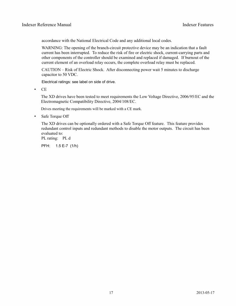
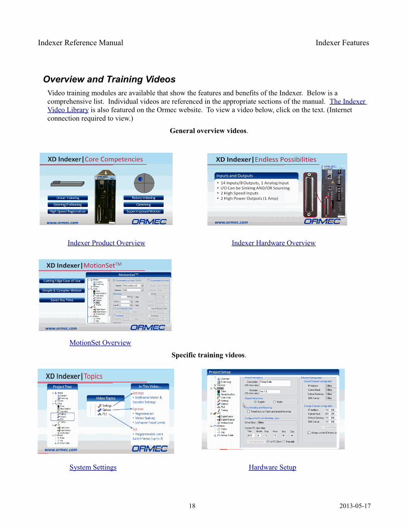
Overview and Training VideosVideo training modules are available that show the features and benefits of the Indexer. Below is a comprehensive list. Individual videos are referenced in the appropriate sections of the manual. The Indexer Video Library is also featured on the Ormec website. To view a video below, click on the text. (Internet connection required to view.)
General overview videos.
Indexer Product Overview Indexer Hardware Overview
MotionSet Overview
Specific training videos.
System Settings Hardware Setup
18 2013-05-17
Indexer Reference Manual Indexer Features
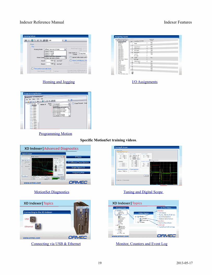
Homing and Jogging I/O Assignments
Programming Motion
Specific MotionSet training videos.
MotionSet Diagnostics Tuning and Digital Scope
Connecting via USB & Ethernet Monitor, Counters and Event Log
19 2013-05-17
Indexer Reference Manual Implementation Guidelines
Implementation Guidelines This section includes basic guidelines for installation and use of XD Indexers. Following these guidelines can significantly improve the performance of the complete system. While failure to follow these guidelines does not insure problems, poor practices lead to poor performance.
This checklist provides an overview, details follow.
Attach safety grounds Mount to a grounded metal panel Separate motor and feedback cables Use shielded feedback and motor cables Use fuses or circuit breakers and line filters on inputs Keep the Indexer cool for extended life Use sufficient wire gauge for input power
Read the safety precautions Be sure to read, understand and follow all of the precautions listed under “Safety Precautions”.
Read the manual This installation manual contains detailed information for correctly connecting and using this equipment. Be sure to read and understand the equipment and features you use.
Grounding for return currents This drive must be grounded using one of the safety ground connections, found on TB1 and TB2. Large drives with TB6 must also have the ground terminal connected. It is also highly recommended that the drive be mounted on a grounded metal panel, with paint scraped at the mounting points. Bolt threads alone are not a sufficient conductor.
Current from the drive to the motor will induce return currents into surrounding conductors and enclosures. Proper grounding controls the return path, improving operation.
Separate motor cables Separate motor power cables and encoder feedback cables.
Motor power conductors (connected to terminal U, V and W) can contain high voltages and currents and radiate noise. Feedback cables are low voltage signals. Do not run them in the same wire channel. Separation by at least 6 inches is recommended.
Use shielded motor cables Cables for motor power and encoder feedback should be shielded and the shields grounded.
Use of shielding significantly reduces the electrical emissions out of cables and coupling into cables. Shields must be grounded to be effective.
20 2013-05-17
Indexer Reference Manual Implementation Guidelines
Fuses and line filters Input power, both control and main power should be protected by fuses or circuit breakers.
Careful consideration should be given to the use of input filters on both control and main power supplies. These devices serve to protect the Indexer (servodrive) from external noise and also to limit the noise injected back onto the line.
Mount for cooling The temperature ratings of the Indexer (servodrive) are for the ambient temperature at the drive. Typical enclosures trap heat and can have a higher internal temperature than the outside ambient. This may require cooling the enclosure or circulating or venting air inside the enclosure so that the Indexer ambient temperature remains within specifications.
Use sufficient wires Use wiring which is of sufficient gauge, temperature and insulation rating. Temperature ratings of at least 80o
C and insulation ratings at least double the input voltage are recommended.
Typical installations are in environments with elevated temperature. In addition, operation of controls which move large amounts of energy give off heat.
Switching characteristics and starting and stopping of motors will produce voltages which are higher than the line voltage. Additional insulation rating is required for protection.
21 2013-05-17
Indexer Reference Manual Decoding Model Numbers
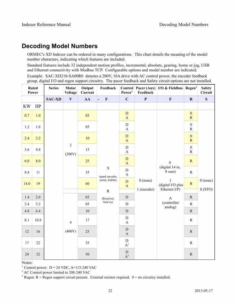
Decoding Model Numbers ORMEC's XD Indexer can be ordered in many configurations. This chart details the meaning of the model number characters, indicating which features are included.Standard features include 32 independent motion profiles, incremental, absolute, gearing, home or jog, USB and Ethernet connectivity with Modbus TCP. Configurable options and model number are indicated.Example: SAC-XD210-SA00R0 denotes a 200V, 10A drive with AC control power, the encoder feedback group, digital I/O and regen support circuitry. The pacer feedback and Safety circuit options are not installed.
Rated Power
Series Motor Voltage
Output Current
Feedback Control Power1
Pacer (Aux) Feedback
I/O & Fieldbus Regen3 Safety Circuit
SAC-XD V AA - F C P F R S
KW HP
0.7 1.0
2
(200V)
03
S
(quad encoder, serial, EnDat)
R
(Resolver, SinCos)
DA
0 (none)
1 (encoder)
0 (digital:14 in,
8 outs)
1 (digital I/O plus
Ethernet I/P)
A (controller/
analog)
0R
0 (none)
S (STO)
1.2 1.6 05 DA
0R
2.4 3.2 10 DA
0R
3.6 4.8 15 DA
0R
6.0 8.0 25 DA R
8.4 11 35 DA R
14.0 19 60 DA R
1.4 2.0
4
(400V)
03 D R
2.4 3.2 05 D R
4.8 6.4 10 D R
8.1 10.9 17 DA R
12 16 25 DA R
17 22 35 DA2 R
24 32 50 DA2 R
Notes:1 Control power: D = 24 VDC, A=115-240 VAC2 AC Control power limited to 208-240 VAC3 Regen: R = Regen support circuit present. External resistor required. 0 = no circuitry installed.
22 2013-05-17
Indexer Reference Manual Quickstart
Quickstart
This “Quickstart” chapter provides a fast overview. It is written for qualified personnel. Qualified personnel are persons who by way of training or experience and instruction of automation equipment and electronics, are authorized to install, commission and service hazardous electronic equipment. Qualified personnel are aware of pertinent standards and safety precautions and follow them. Quickstart guides you through getting a quick test running. It does not provide detailed documentation that will eventually be needed. If you desire more guidance, skip this section and go to Connecting to the Indexer .
The simplest and fastest way to get started is to use an integrated system from ORMEC. With ORMEC motors and cables you can connect and configure quickly. Quickstart assumes you are using ORMEC motors. If not you will need to add a step or two.
The overview which directly follows is a quick guide to getting started, with few explanations. If you would prefer a more detailed explanation please use either of Step Q 1: Connect to the Indexer or Connecting to theIndexer
Quickstart Overview What you'll need:
1. A computer with Internet access and an Ethernet port or USB port.
2. For Ethernet communications a crossover Ethernet cable. For USB communications a USB 2.0 A/B cable. (Type A male to type B male connectors.)
3. A small screwdriver.
4. Wire to connect power.
Getting Started:
You're eager to get connected and see your motor spinning. This Getting Started guide is designed to walk you to that goal. However, it is a simplified guide. If at any time you have questions please stop and consult the complete Reference Manual.
Warning: You are working with industrial equipment, not a consumer product. It is designed to be installed and operated by qualified personnel. Qualified personnel are persons who by way of training or experience and instruction of automation equipment and electronics are authorized to install, commission and service hazardous electronic equipment. Qualified personnel are aware of pertinent standards and safety precautions and follow them.
Incorrect procedures can result in injury to people and equipment, possibly serious, including death.
The simplest and fastest way to get started is to use an integrated system from ORMEC. With ORMEC motors and cables you can connect quickly, all the connectors are provided and designed to plug together. Quickstart assumes you are using ORMEC motors. If not you will need to add an additional step or two putting together cables.
Let's get started.
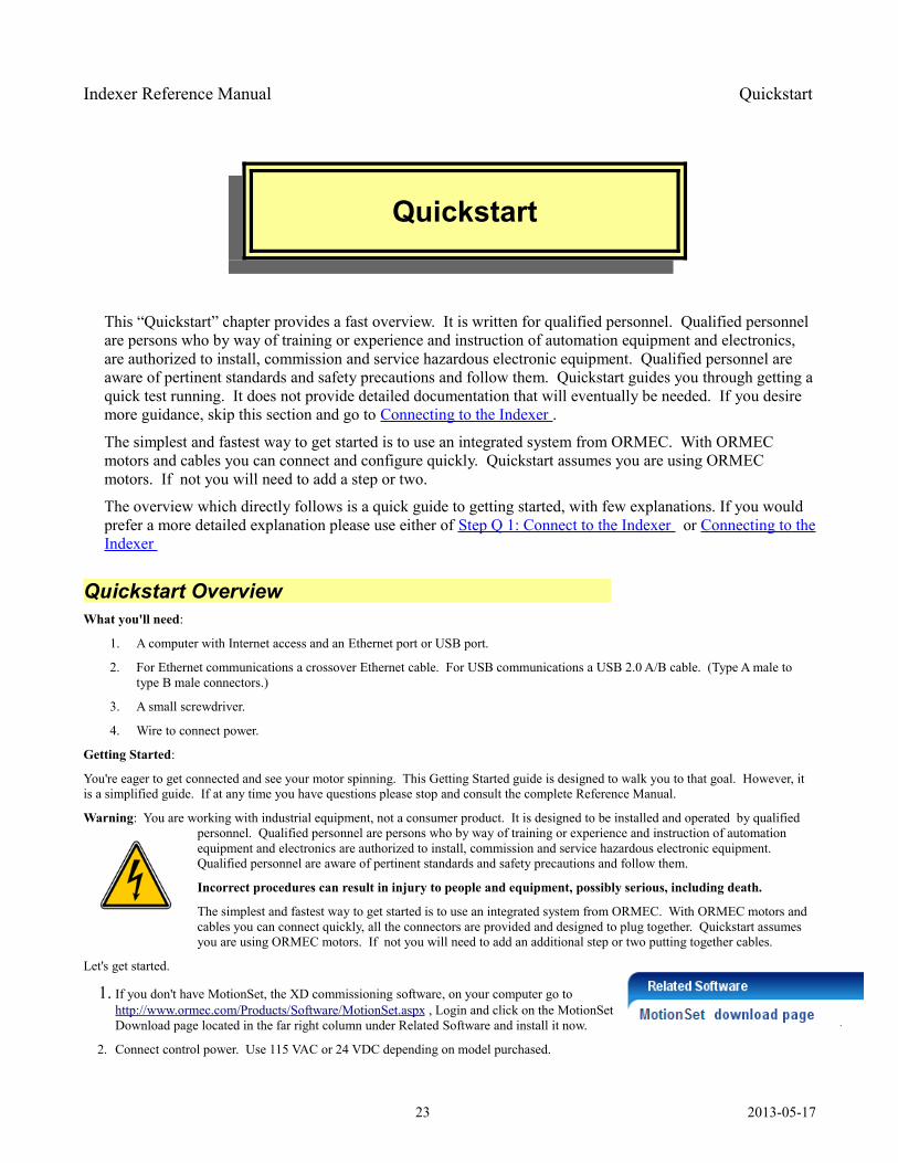
1. If you don't have MotionSet, the XD commissioning software, on your computer go to http://www.ormec.com/Products/ Software / MotionSet .aspx , Login and click on the MotionSet Download page located in the far right column under Related Software and install it now.
2. Connect control power. Use 115 VAC or 24 VDC depending on model purchased.
23 2013-05-17
Indexer Reference Manual Quickstart
a) DC uses TB1 pins 24V, 24R and FG. (Model numbers SAC-XD***-*D)
b) AC uses TB2 pins r and t. (Model numbers SAC-XD***-*A)
3. Connect main power (incoming motor bus power) on TB2 single phase or 3 phase using pins L1, L2 and L3. Do NOT exceed motor rating. XD2xx – Use 115 or 230 VAC, XD4xx – use 230 or 460 VAC.
4. Connect the motor. Feedback to J6 on the bottom, power to TB4 or TB2 on the front, for XD2xx or XD4xx respectively. With an ORMEC cable Red to U, white to V, black to W, green to GND and shield to SH.
5. Run (open) MotionSet commissioning software. After MotionSet starts select File then New from the menu.
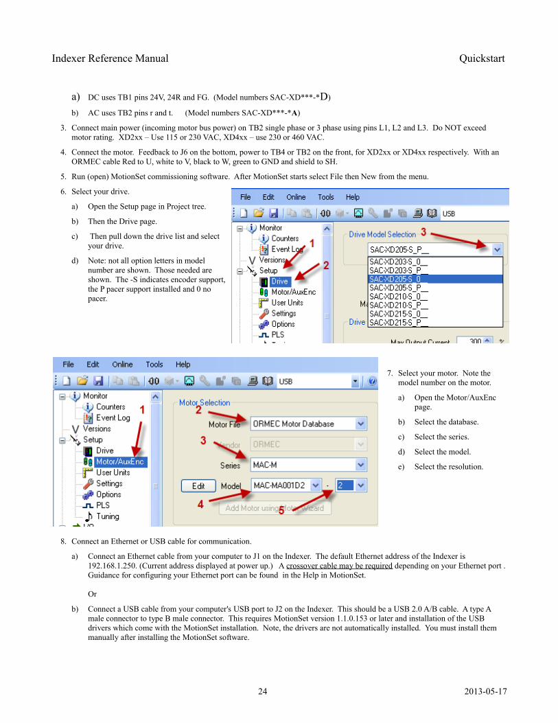
6. Select your drive.
a) Open the Setup page in Project tree.
b) Then the Drive page.
c) Then pull down the drive list and select your drive.
d) Note: not all option letters in model number are shown. Those needed are shown. The -S indicates encoder support, the P pacer support installed and 0 no pacer.
7. Select your motor. Note the model number on the motor.
a) Open the Motor/AuxEnc page.
b) Select the database.
c) Select the series.
d) Select the model.
e) Select the resolution.
8. Connect an Ethernet or USB cable for communication.
a) Connect an Ethernet cable from your computer to J1 on the Indexer. The default Ethernet address of the Indexer is 192.168.1.250. (Current address displayed at power up.) A crossover cable may be required depending on your Ethernet port . Guidance for configuring your Ethernet port can be found in the Help in MotionSet.
Or
b) Connect a USB cable from your computer's USB port to J2 on the Indexer. This should be a USB 2.0 A/B cable. A type A male connector to type B male connector. This requires MotionSet version 1.1.0.153 or later and installation of the USB drivers which come with the MotionSet installation. Note, the drivers are not automatically installed. You must install them manually after installing the MotionSet software.
24 2013-05-17
Indexer Reference Manual Quickstart
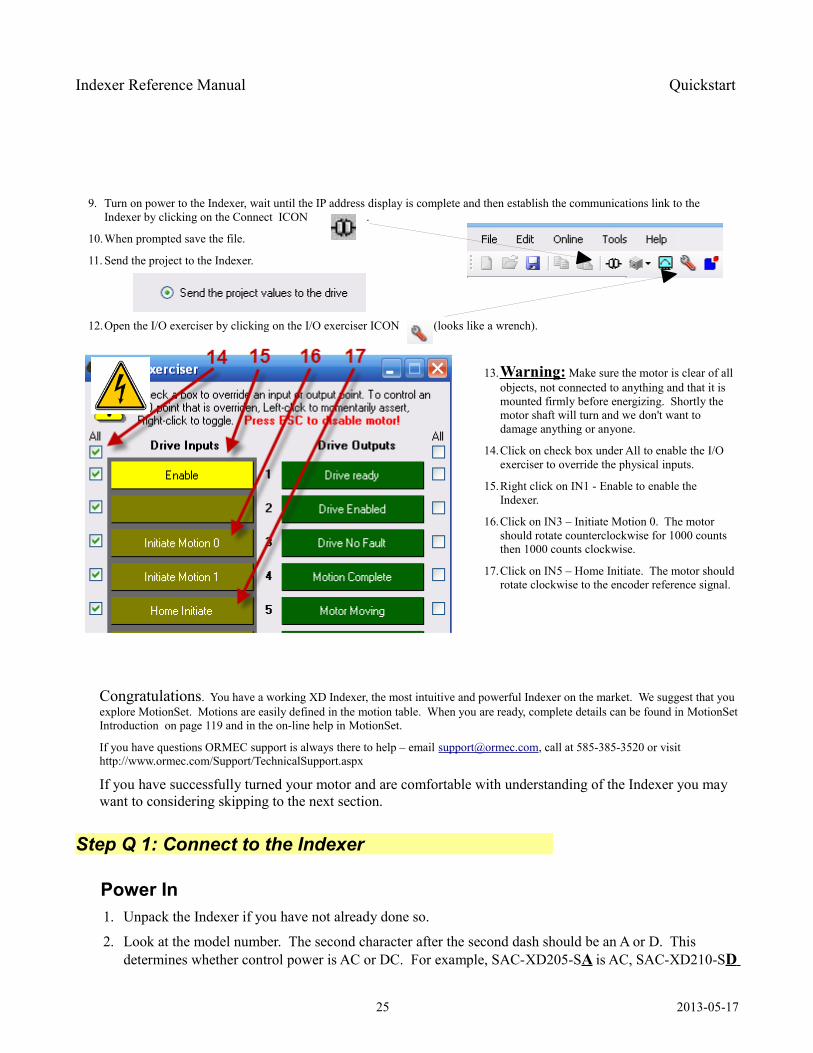
9. Turn on power to the Indexer, wait until the IP address display is complete and then establish the communications link to the Indexer by clicking on the Connect ICON .
10.When prompted save the file.
11. Send the project to the Indexer.
12.Open the I/O exerciser by clicking on the I/O exerciser ICON (looks like a wrench).
13.Warning: Make sure the motor is clear of all objects, not connected to anything and that it is mounted firmly before energizing. Shortly the motor shaft will turn and we don't want to damage anything or anyone.
14.Click on check box under All to enable the I/O exerciser to override the physical inputs.
15.Right click on IN1 - Enable to enable the Indexer.
16.Click on IN3 – Initiate Motion 0. The motor should rotate counterclockwise for 1000 counts then 1000 counts clockwise.
17.Click on IN5 – Home Initiate. The motor should rotate clockwise to the encoder reference signal.
Congratulations. You have a working XD Indexer, the most intuitive and powerful Indexer on the market. We suggest that you explore MotionSet. Motions are easily defined in the motion table. When you are ready, complete details can be found in MotionSetIntroduction on page 119 and in the on-line help in MotionSet.
If you have questions ORMEC support is always there to help – email [email protected], call at 585-385-3520 or visit http://www.ormec.com/Support/TechnicalSupport.aspx
If you have successfully turned your motor and are comfortable with understanding of the Indexer you may want to considering skipping to the next section.
Step Q 1: Connect to the Indexer
Power In 1. Unpack the Indexer if you have not already done so.
2. Look at the model number. The second character after the second dash should be an A or D. This determines whether control power is AC or DC. For example, SAC-XD205-SA is AC, SAC-XD210-SD
25 2013-05-17
Indexer Reference Manual Quickstart
is 24v DC.
3. If AC input connect 115 VAC to pins r and t on terminal block TB2. Connect safety ground to FG.
4. If DC input connect 24 VDC to pins 24V and 24R on terminal block TB1. Connect a safety ground to FG.
5. Connect 115 VAC to TB2 pins L1 and L2. This will provide motor power. Note, if you have a 230 V motor you will not be able to reach full speed. You will be limited to ½ of rated speed. Connect 230 VAC if you prefer and the motor is rated for 230 VAC. Note, 460 VAC drives, XD4xx, require 3-phase input. Use L1, L2 and L3. Voltage can be up to 460 VAC if the motor is rated for 460 VAC. Logic power, r and t, are limited to 230 VAC.
Motor Connections 1. Connect the motor power leads to TB4 or TB6, depending on model. If you have an ORMEC motor
cable then RED goes to U, WHITE to V, BLACK to W, GREEN to GND and the shield to SH.
2. Connect the motor feedback cable to J6 on the bottom of the Indexer. If you have an ORMEC encoder cable it will plug on. If not you will need to make a suitable cable using the pinout documented in section Step C 5: Connect motor feedback
Commissioning Software (GUI) Connections 1. Connect an Ethernet cable from J1 on the Indexer to your computer or a USB cable from J2 on the
Indexer to your computer.
a) For Ethernet, a crossover cable may be required.
b) For USB, a USB 2.0 A/B cable will be required.
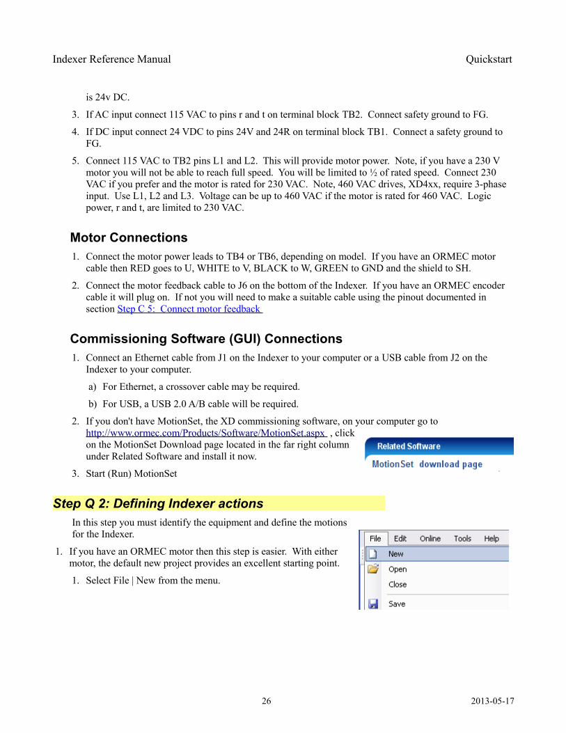
2. If you don't have MotionSet, the XD commissioning software, on your computer go to http://www.ormec.com/Products/ Software / MotionSet .aspx , click on the MotionSet Download page located in the far right column under Related Software and install it now.
3. Start (Run) MotionSet
Step Q 2: Defining Indexer actions In this step you must identify the equipment and define the motions for the Indexer.
1. If you have an ORMEC motor then this step is easier. With either motor, the default new project provides an excellent starting point.
1. Select File | New from the menu.
26 2013-05-17
Indexer Reference Manual Quickstart
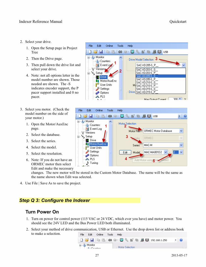
2. Select your drive.
1. Open the Setup page in Project Tree
2. Then the Drive page.
3. Then pull down the drive list and select your drive.
4. Note: not all options letter in the model number are shown. Those needed are shown. The -S indicates encoder support, the P pacer support installed and 0 no pacer.
3. Select you motor. (Check the model number on the side of your motor.)
1. Open the Motor/AuxEnc page.
2. Select the database.
3. Select the series.
4. Select the model.
5. Select the resolution.
6. Note: If you do not have an ORMEC motor then select Edit and make the necessary changes. The new motor will be stored in the Custom Motor Database. The name will be the same as the name shown when Edit was selected.
4. Use File | Save As to save the project.
Step Q 3: Configure the Indexer
Turn Power On 1. Turn on power for control power (115 VAC or 24 VDC, which ever you have) and motor power. You
should see the 24V LED and the Bus Power LED both illuminated.
2. Select your method of drive communication, USB or Ethernet. Use the drop down list or address book to make a selection.
27 2013-05-17
Indexer Reference Manual Quickstart
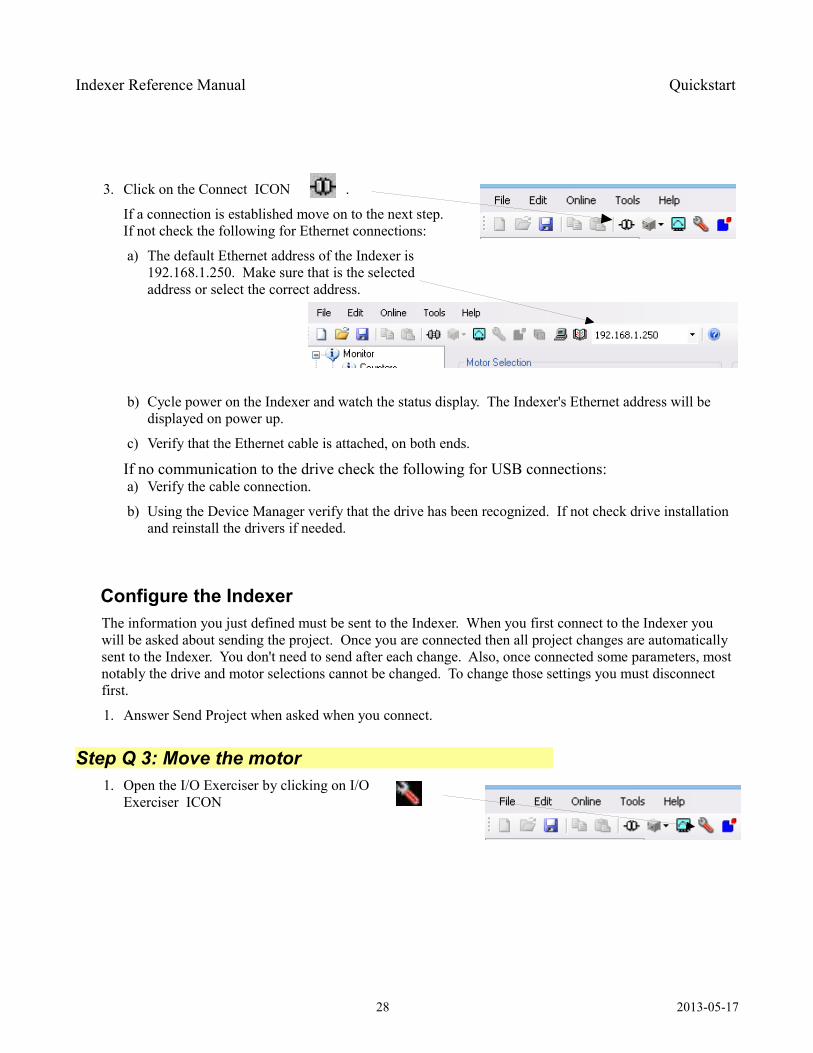
3. Click on the Connect ICON .
If a connection is established move on to the next step. If not check the following for Ethernet connections:
a) The default Ethernet address of the Indexer is 192.168.1.250. Make sure that is the selected address or select the correct address.
b) Cycle power on the Indexer and watch the status display. The Indexer's Ethernet address will be displayed on power up.
c) Verify that the Ethernet cable is attached, on both ends.
If no communication to the drive check the following for USB connections: a) Verify the cable connection.
b) Using the Device Manager verify that the drive has been recognized. If not check drive installation and reinstall the drivers if needed.
Configure the Indexer The information you just defined must be sent to the Indexer. When you first connect to the Indexer you will be asked about sending the project. Once you are connected then all project changes are automatically sent to the Indexer. You don't need to send after each change. Also, once connected some parameters, most notably the drive and motor selections cannot be changed. To change those settings you must disconnect first.
1. Answer Send Project when asked when you connect.
Step Q 3: Move the motor 1. Open the I/O Exerciser by clicking on I/O
Exerciser ICON
28 2013-05-17
Indexer Reference Manual Quickstart
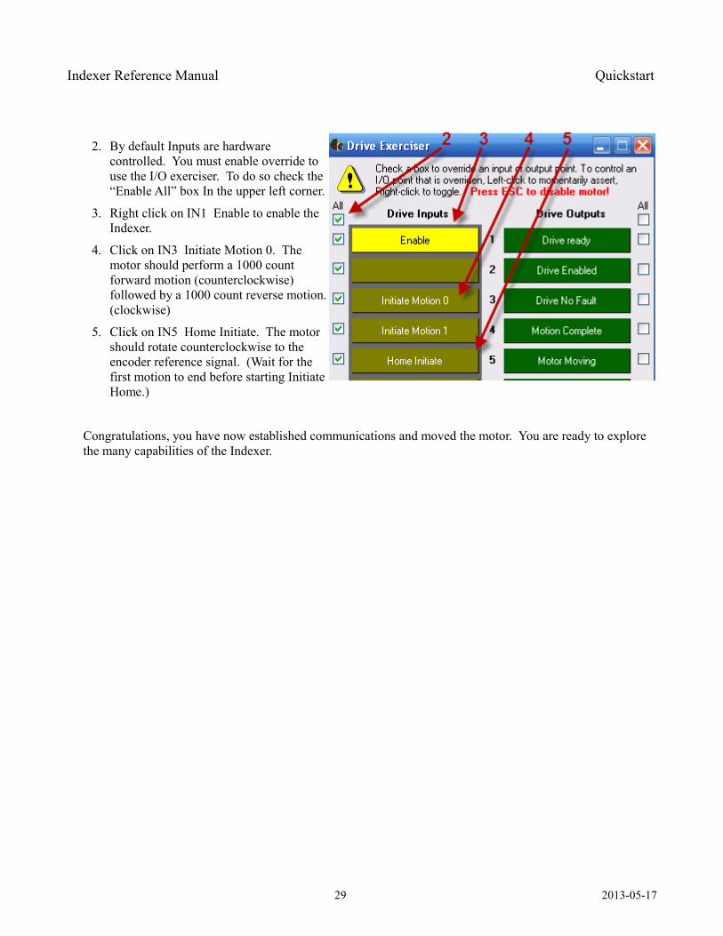
2. By default Inputs are hardware controlled. You must enable override to use the I/O exerciser. To do so check the “Enable All” box In the upper left corner.
3. Right click on IN1 Enable to enable the Indexer.
4. Click on IN3 Initiate Motion 0. The motor should perform a 1000 count forward motion (counterclockwise) followed by a 1000 count reverse motion. (clockwise)
5. Click on IN5 Home Initiate. The motor should rotate counterclockwise to the encoder reference signal. (Wait for the first motion to end before starting Initiate Home.)
Congratulations, you have now established communications and moved the motor. You are ready to explore the many capabilities of the Indexer.
29 2013-05-17
Indexer Reference Manual Connecting to the Indexer
Connecting to the Indexer
This section provides the information needed to connect the Indexer to your machine and application.
Step C 1: Mounting the Indexer Location: The Indexer generates heat during operation. It must be mounted in a location and orientation to allow that heat to dissipate. The better the dissipation the longer the life of the unit. Heat is one of the major factors in the life expectancy of electronics.
The best location is on a metal panel, vertically with space enough around to allow airflow.
Protection: Protect from contamination and contact with other objects. Contaminates such as dirt, oil, corrosive gases, metal filings and other conductive materials must be avoided.
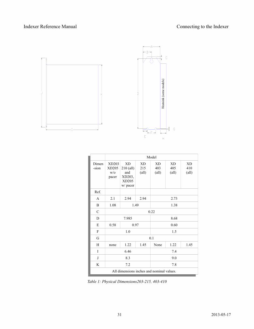
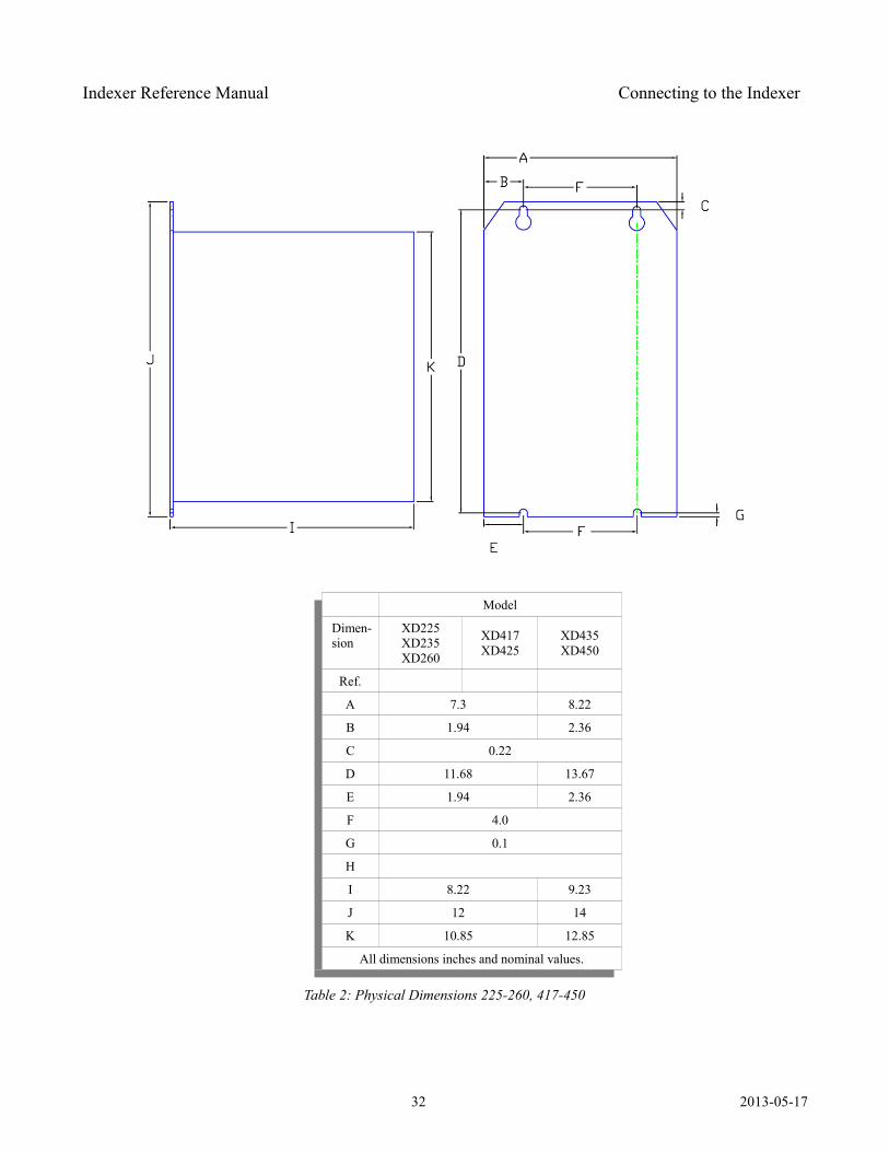
Size: Models SAC-XD203 – SAC-XD215, SAC-XD405-SAC-XD410 are mounted using 3 #10-32 machine screws or equivalent. Models XD225 – XD260 and XD417 – XD450 are mounted using 4 #10-32 machine screws or equivalent.
Additional details can be found in mounting drawings on the ORMEC website, http://www.ormec.com/Products/Drives/XDSeriesIndexerServoDrive.aspx
30 2013-05-17
Hea
tsink
(som
e mod
els)
Indexer Reference Manual Connecting to the Indexer
Model
Dimen-sion
XD203 XD205
w/o pacer
XD210 (all)
and XD203, XD205 w/ pacer
XD215 (all)
XD403(all)
XD405(all)
XD410(all)
Ref.
A 2.1 2.94 2.94 2.73
B 1.08 1.49 1.38
C 0.22
D 7.985 8.68
E 0.58 0.97 0.60
F 1.0 1.5
G 0.1
H none 1.22 1.45 None 1.22 1.45
I 6.46 7.4
J 8.3 9.0
K 7.2 7.8
All dimensions inches and nominal values.
Table 1: Physical Dimensions203-215, 403-410
31 2013-05-17
Indexer Reference Manual Connecting to the Indexer
Model
Dimen-sion
XD225XD235XD260
XD417XD425
XD435XD450
Ref.
A 7.3 8.22
B 1.94 2.36
C 0.22
D 11.68 13.67
E 1.94 2.36
F 4.0
G 0.1
H
I 8.22 9.23
J 12 14
K 10.85 12.85
All dimensions inches and nominal values.
Table 2: Physical Dimensions 225-260, 417-450
32 2013-05-17
Indexer Reference Manual Connecting to the Indexer
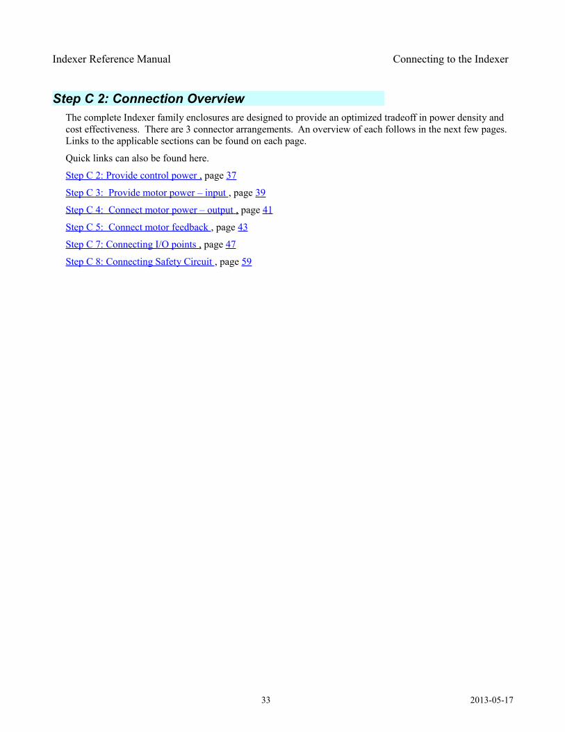
Step C 2: Connection Overview The complete Indexer family enclosures are designed to provide an optimized tradeoff in power density and cost effectiveness. There are 3 connector arrangements. An overview of each follows in the next few pages. Links to the applicable sections can be found on each page.
Quick links can also be found here.
Step C 2: Provide control power , page 37
Step C 3: Provide motor power – input , page 39
Step C 4: Connect motor power – output , page 41
Step C 5: Connect motor feedback , page 43
Step C 7: Connecting I/O points , page 47
Step C 8: Connecting Safety Circuit , page 59
33 2013-05-17
Indexer Reference Manual Connecting to the Indexer
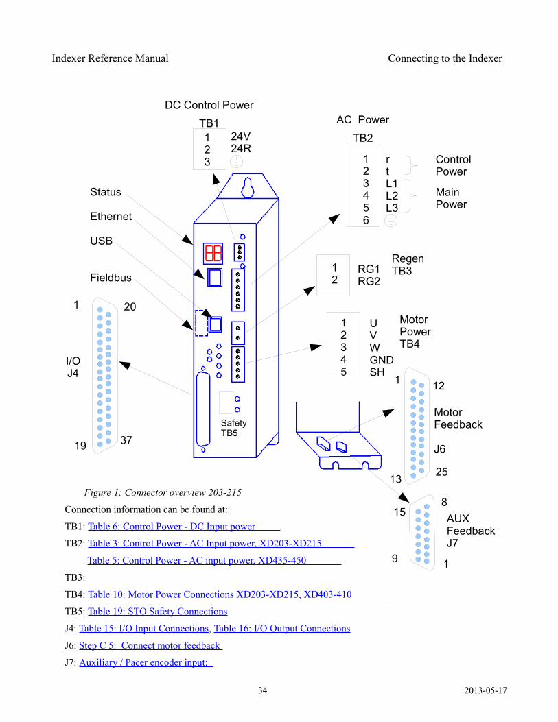
Figure 1: Connector overview 203-215
Connection information can be found at:
TB1: Table 6: Control Power - DC Input power
TB2: Table 3: Control Power - AC Input power, XD203-XD215
Table 5: Control Power - AC input power, XD435-450
TB3:
TB4: Table 10: Motor Power Connections XD203-XD215, XD403-410
TB5: Table 19: STO Safety Connections
J4: Table 15: I/O Input Connections, Table 16: I/O Output Connections
J6: Step C 5: Connect motor feedback
J7: Auxiliary / Pacer encoder input:
34 2013-05-17
123
24V24R
Status
Ethernet
USB
Fieldbus
1 20
19
DC Control Power
TB1TB1
rtL1L2L3
123456
AC Power
TB2
12345
UVWGNDSH
Main Power
RegenTB3
MotorPowerTB4
MotorFeedback
J6
12
37
1
1325
1
8
I/OJ4
15 AUXFeedbackJ7
Control Power
12
RG1RG2
9
SafetyTB5
Indexer Reference Manual Connecting to the Indexer
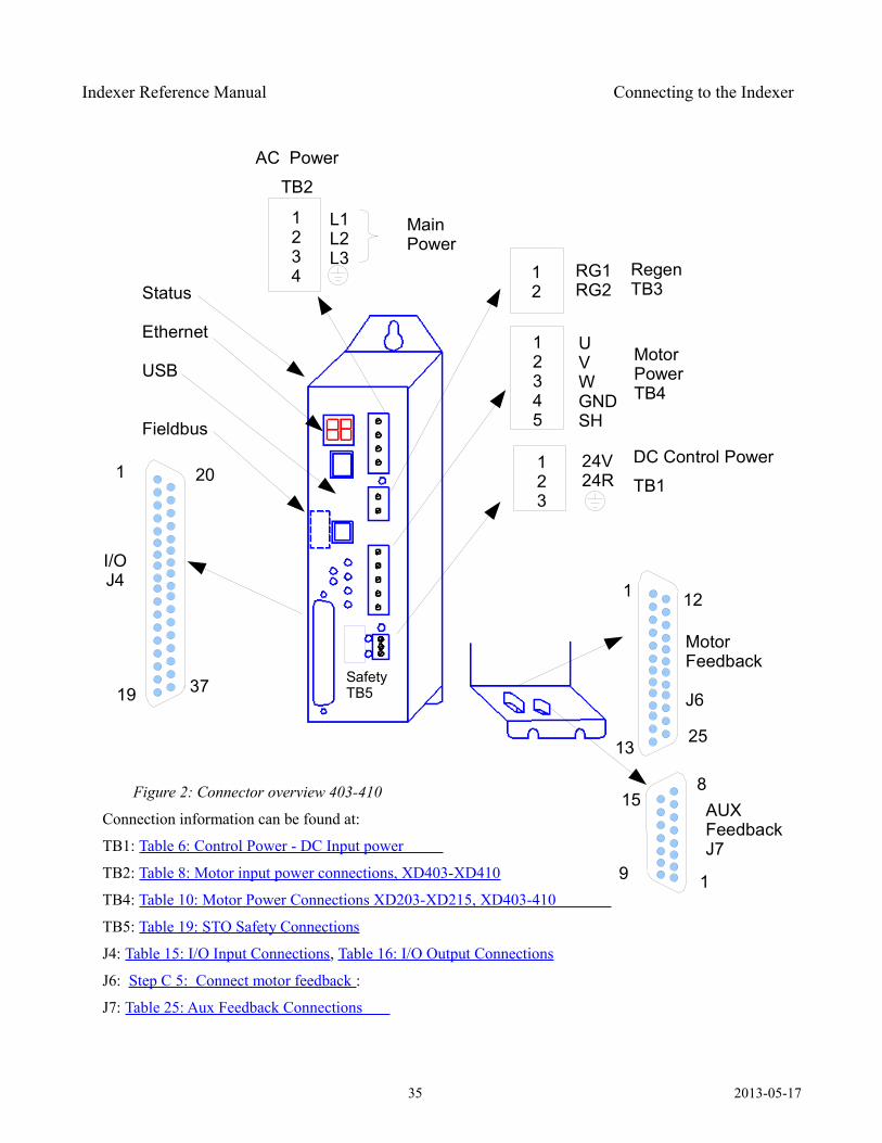
Figure 2: Connector overview 403-410
Connection information can be found at:
TB1: Table 6: Control Power - DC Input power
TB2: Table 8: Motor input power connections, XD403-XD410
TB4: Table 10: Motor Power Connections XD203-XD215, XD403-410
TB5: Table 19: STO Safety Connections
J4: Table 15: I/O Input Connections, Table 16: I/O Output Connections
J6: Step C 5: Connect motor feedback :
J7: Table 25: Aux Feedback Connections
35 2013-05-17
123
24V24R
Status
Ethernet
USB
Fieldbus
1 20
19
DC Control Power
TB1
L1L2L3
1234
AC Power
TB2
12345
UVWGNDSH
Main Power
RegenTB3
MotorPowerTB4
MotorFeedback
J6
12
37
1
1325
1
8
I/OJ4
15 AUXFeedbackJ7
12
RG1RG2
9
SafetyTB5
Indexer Reference Manual Connecting to the Indexer
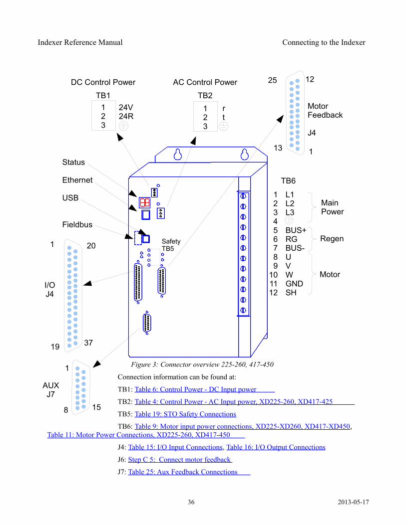
Figure 3: Connector overview 225-260, 417-450 Connection information can be found at:
TB1: Table 6: Control Power - DC Input power
TB2: Table 4: Control Power - AC Input power, XD225-260, XD417-425
TB5: Table 19: STO Safety Connections
TB6: Table 9: Motor input power connections, XD225-XD260, XD417-XD450, Table 11: Motor Power Connections, XD225-260, XD417-450
J4: Table 15: I/O Input Connections, Table 16: I/O Output Connections
J6: Step C 5: Connect motor feedback
J7: Table 25: Aux Feedback Connections
36 2013-05-17
123
24V24R
Status
Ethernet
USB
Fieldbus
1 20
19
DC Control Power
TB1rt
123
AC Control Power
TB2
123456789
101112
L1L2L3
BUS+RGBUS-UVWGNDSH
Main Power
Regen
Motor
MotorFeedback
J4
12
37
113
25
1
8
I/OJ4
15
AUXJ7
TB6
SafetyTB5
Indexer Reference Manual Connecting to the Indexer
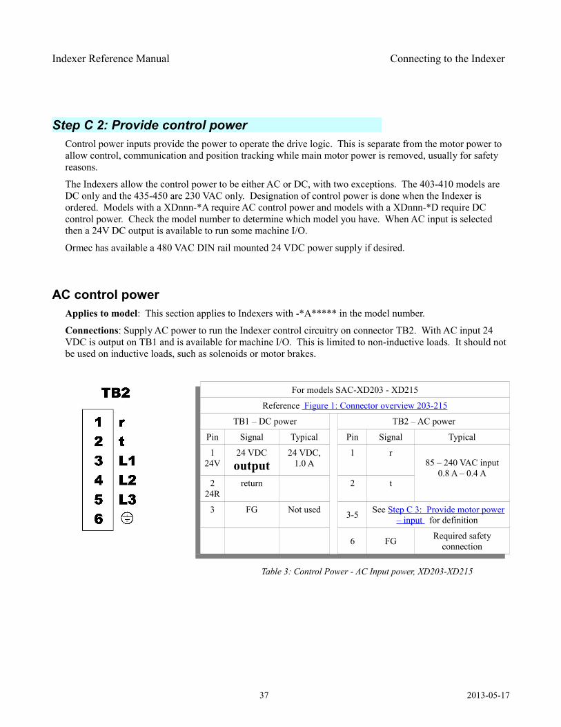
Step C 2: Provide control power Control power inputs provide the power to operate the drive logic. This is separate from the motor power to allow control, communication and position tracking while main motor power is removed, usually for safety reasons.
The Indexers allow the control power to be either AC or DC, with two exceptions. The 403-410 models are DC only and the 435-450 are 230 VAC only. Designation of control power is done when the Indexer is ordered. Models with a XDnnn-*A require AC control power and models with a XDnnn-*D require DC control power. Check the model number to determine which model you have. When AC input is selected then a 24V DC output is available to run some machine I/O.
Ormec has available a 480 VAC DIN rail mounted 24 VDC power supply if desired.
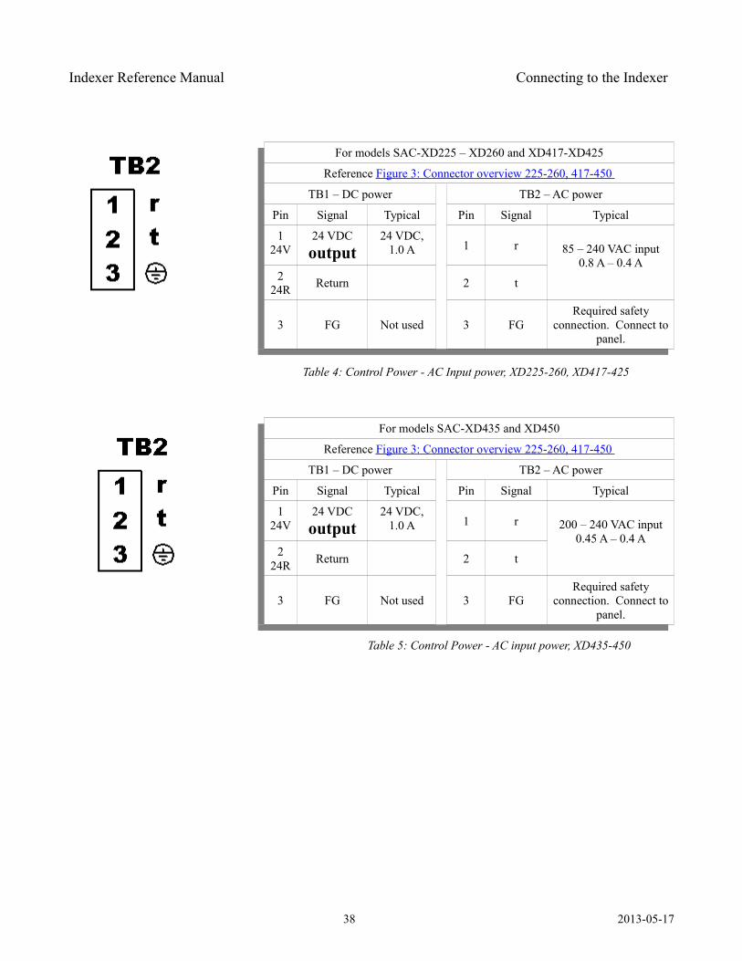
AC control power Applies to model: This section applies to Indexers with -*A***** in the model number.
Connections: Supply AC power to run the Indexer control circuitry on connector TB2. With AC input 24 VDC is output on TB1 and is available for machine I/O. This is limited to non-inductive loads. It should not be used on inductive loads, such as solenoids or motor brakes.
For models SAC-XD203 - XD215
Reference Figure 1: Connector overview 203-215
TB1 – DC power TB2 – AC power
Pin Signal Typical Pin Signal Typical
1 24V
24 VDC output
24 VDC,1.0 A
1 r85 – 240 VAC input
0.8 A – 0.4 A2
24Rreturn 2 t
3 FG Not used 3-5 See Step C 3: Provide motor power– input for definition
6 FG Required safety connection
Table 3: Control Power - AC Input power, XD203-XD215
37 2013-05-17
Indexer Reference Manual Connecting to the Indexer
For models SAC-XD225 – XD260 and XD417-XD425
Reference Figure 3: Connector overview 225-260, 417-450
TB1 – DC power TB2 – AC power
Pin Signal Typical Pin Signal Typical
1 24V
24 VDC output
24 VDC,1.0 A 1 r 85 – 240 VAC input
0.8 A – 0.4 A2
24R Return 2 t
3 FG Not used 3 FGRequired safety
connection. Connect to panel.
Table 4: Control Power - AC Input power, XD225-260, XD417-425
For models SAC-XD435 and XD450
Reference Figure 3: Connector overview 225-260, 417-450
TB1 – DC power TB2 – AC power
Pin Signal Typical Pin Signal Typical
1 24V
24 VDC output
24 VDC,1.0 A 1 r 200 – 240 VAC input
0.45 A – 0.4 A2
24R Return 2 t
3 FG Not used 3 FGRequired safety
connection. Connect to panel.
Table 5: Control Power - AC input power, XD435-450
38 2013-05-17
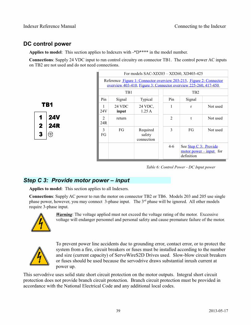
Indexer Reference Manual Connecting to the Indexer
DC control power Applies to model: This section applies to Indexers with -*D**** in the model number.
Connections: Supply 24 VDC input to run control circuitry on connector TB1. The control power AC inputs on TB2 are not used and do not need connections.
For models SAC-XD203 – XD260, XD403-425
Reference Figure 1: Connector overview 203-215, Figure 2: Connectoroverview 403-410, Figure 3: Connector overview 225-260, 417-450
TB1 TB2
Pin Signal Typical Pin Signal
1 24V
24 VDC input
24 VDC,1.25 A
1 r Not used
2 24R
return 2 t Not used
3 FG
FG Required safety
connection
3 FG Not used
4-6 See Step C 3: Providemotor power – input for definition
Table 6: Control Power - DC Input power
Step C 3: Provide motor power – input Applies to model: This section applies to all Indexers.
Connections: Supply AC power to run the motor on connector TB2 or TB6. Models 203 and 205 use single phase power, however, you may connect 3-phase input. The 3rd phase will be ignored. All other models require 3-phase input.
Warning: The voltage applied must not exceed the voltage rating of the motor. Excessive voltage will endanger personnel and personal safety and cause premature failure of the motor.
To prevent power line accidents due to grounding error, contact error, or to protect the system from a fire, circuit breakers or fuses must be installed according to the number and size (current capacity) of ServoWireS2D Drives used. Slow-blow circuit breakers or fuses should be used because the servodrive draws substantial inrush current at power up.
This servodrive uses solid state short circuit protection on the motor outputs. Integral short circuit protection does not provide branch circuit protection. Branch circuit protection must be provided in accordance with the National Electrical Code and any additional local codes.
39 2013-05-17
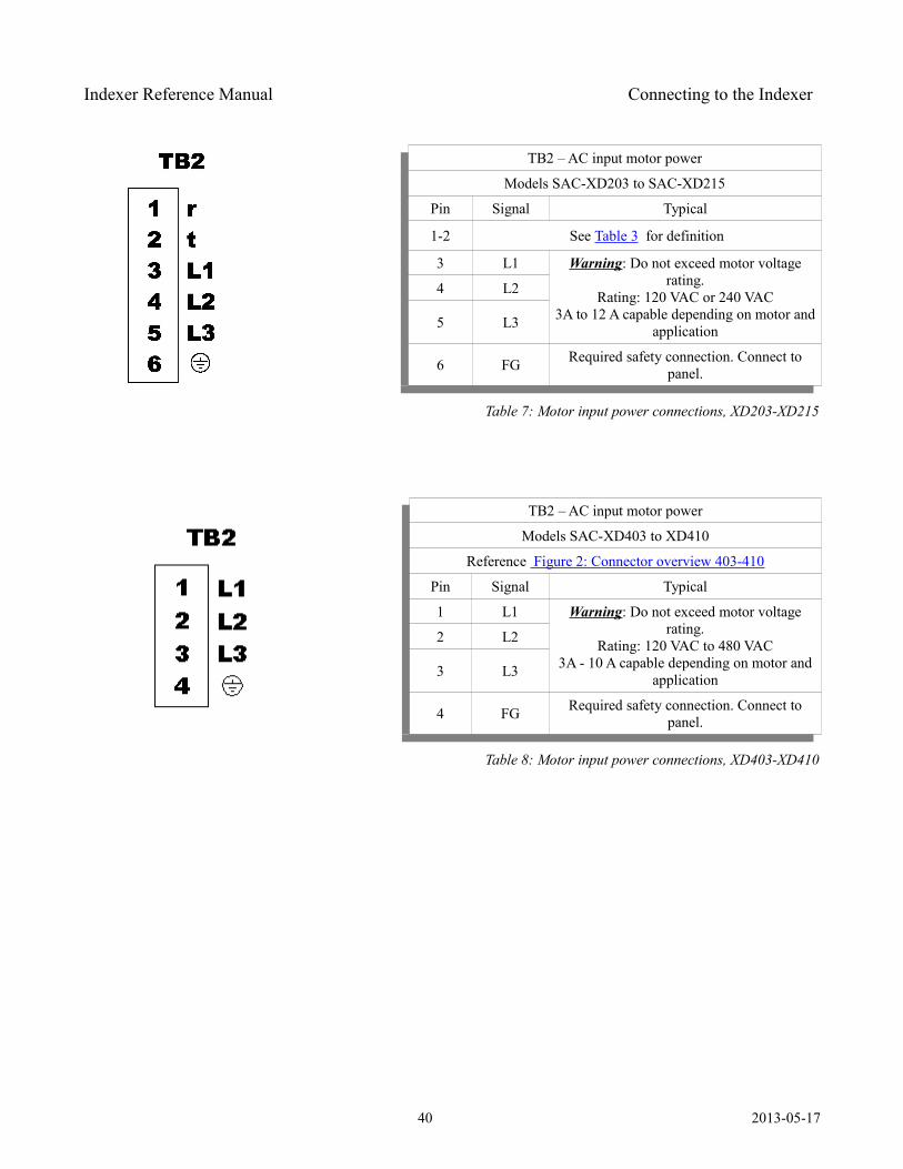
Indexer Reference Manual Connecting to the Indexer
TB2 – AC input motor power
Models SAC-XD203 to SAC-XD215
Pin Signal Typical
1-2 See Table 3 for definition
3 L1 Warning: Do not exceed motor voltage rating.
Rating: 120 VAC or 240 VAC3A to 12 A capable depending on motor and
application
4 L2
5 L3
6 FG Required safety connection. Connect to panel.
Table 7: Motor input power connections, XD203-XD215
TB2 – AC input motor power
Models SAC-XD403 to XD410
Reference Figure 2: Connector overview 403-410
Pin Signal Typical
1 L1 Warning: Do not exceed motor voltage rating.
Rating: 120 VAC to 480 VAC3A - 10 A capable depending on motor and
application
2 L2
3 L3
4 FG Required safety connection. Connect to panel.
Table 8: Motor input power connections, XD403-XD410
40 2013-05-17
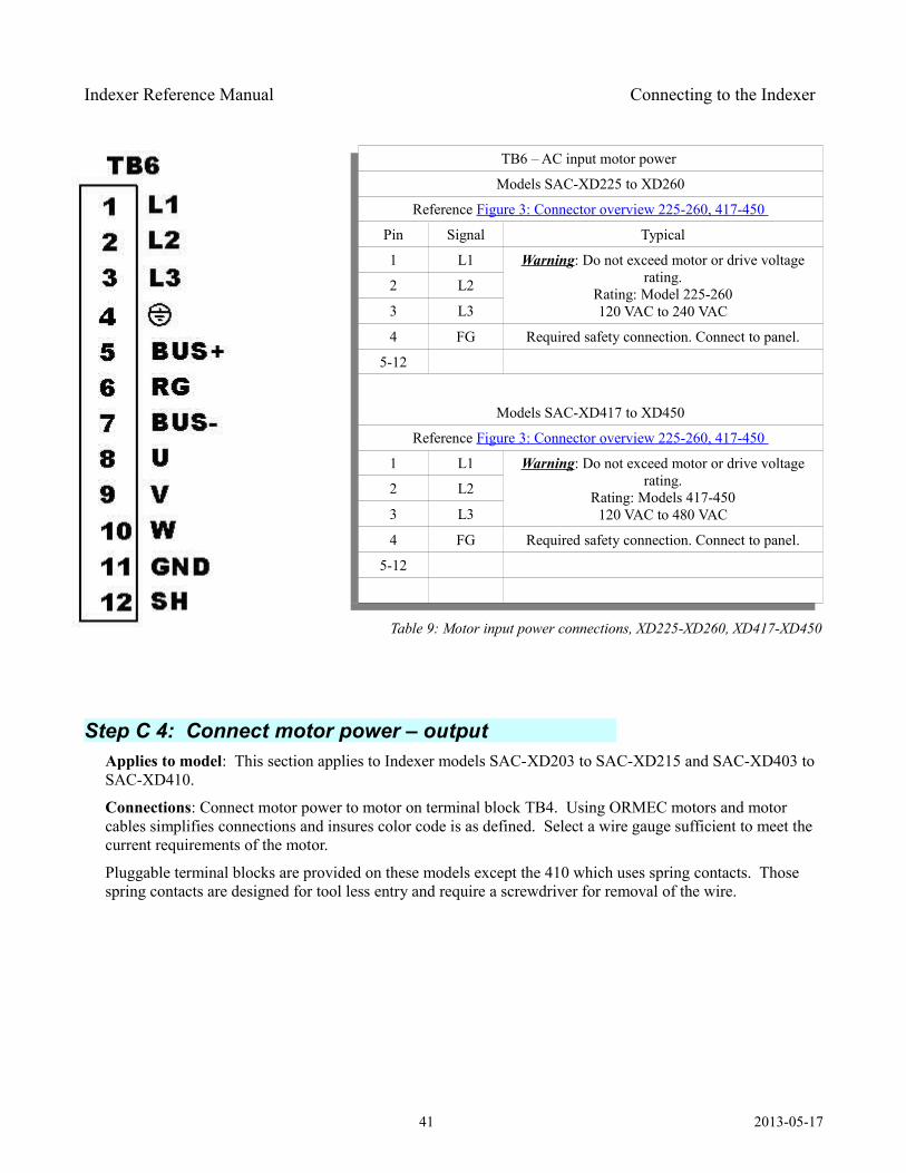
Indexer Reference Manual Connecting to the Indexer
TB6 – AC input motor power
Models SAC-XD225 to XD260
Reference Figure 3: Connector overview 225-260, 417-450
Pin Signal Typical
1 L1 Warning: Do not exceed motor or drive voltage rating.
Rating: Model 225-260120 VAC to 240 VAC
2 L2
3 L3
4 FG Required safety connection. Connect to panel.
5-12
Models SAC-XD417 to XD450
Reference Figure 3: Connector overview 225-260, 417-450
1 L1 Warning: Do not exceed motor or drive voltage rating.
Rating: Models 417-450120 VAC to 480 VAC
2 L2
3 L3
4 FG Required safety connection. Connect to panel.
5-12
Table 9: Motor input power connections, XD225-XD260, XD417-XD450
Step C 4: Connect motor power – output Applies to model: This section applies to Indexer models SAC-XD203 to SAC-XD215 and SAC-XD403 to SAC-XD410.
Connections: Connect motor power to motor on terminal block TB4. Using ORMEC motors and motor cables simplifies connections and insures color code is as defined. Select a wire gauge sufficient to meet the current requirements of the motor.
Pluggable terminal blocks are provided on these models except the 410 which uses spring contacts. Those spring contacts are designed for tool less entry and require a screwdriver for removal of the wire.
41 2013-05-17
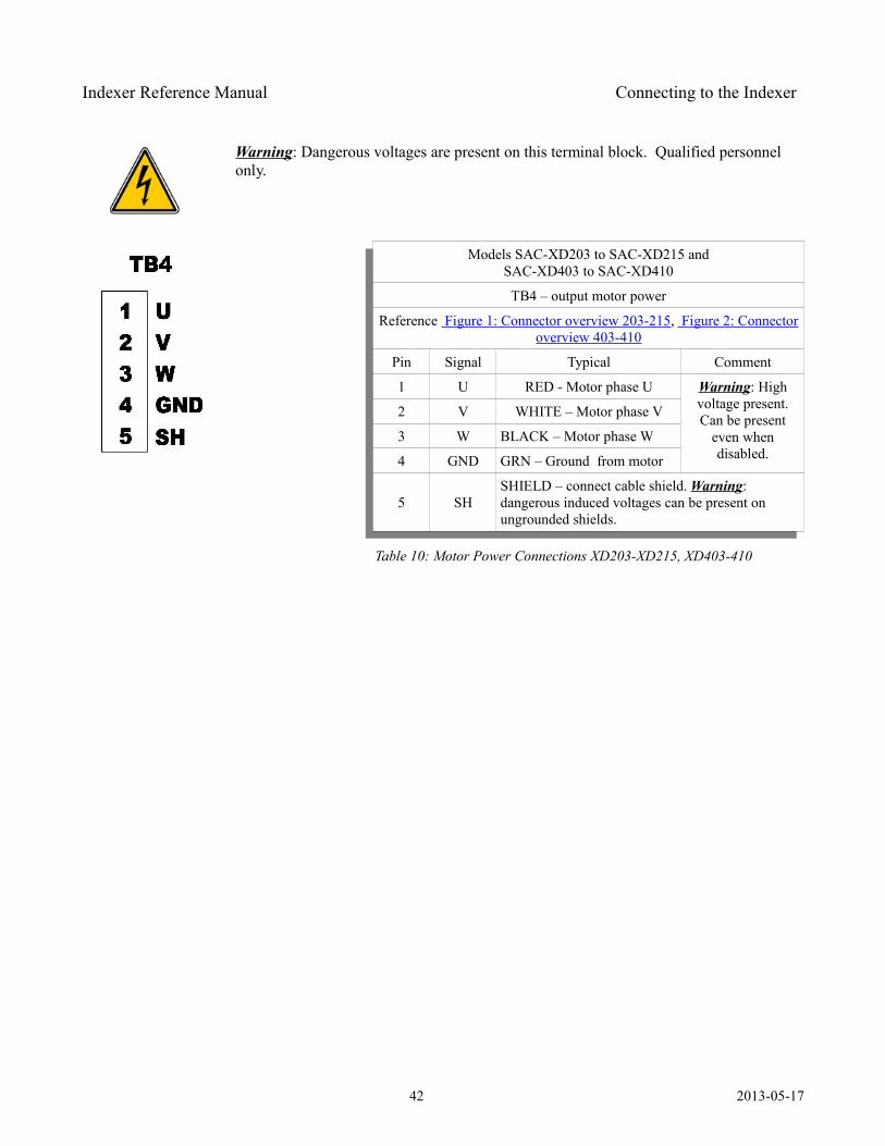
Indexer Reference Manual Connecting to the Indexer
Warning: Dangerous voltages are present on this terminal block. Qualified personnel only.
Models SAC-XD203 to SAC-XD215 andSAC-XD403 to SAC-XD410
TB4 – output motor power
Reference Figure 1: Connector overview 203-215, Figure 2: Connectoroverview 403-410
Pin Signal Typical Comment
1 U RED - Motor phase U Warning: High voltage present. Can be present
even when disabled.
2 V WHITE – Motor phase V
3 W BLACK – Motor phase W
4 GND GRN – Ground from motor
5 SHSHIELD – connect cable shield. Warning: dangerous induced voltages can be present on ungrounded shields.
Table 10: Motor Power Connections XD203-XD215, XD403-410
42 2013-05-17
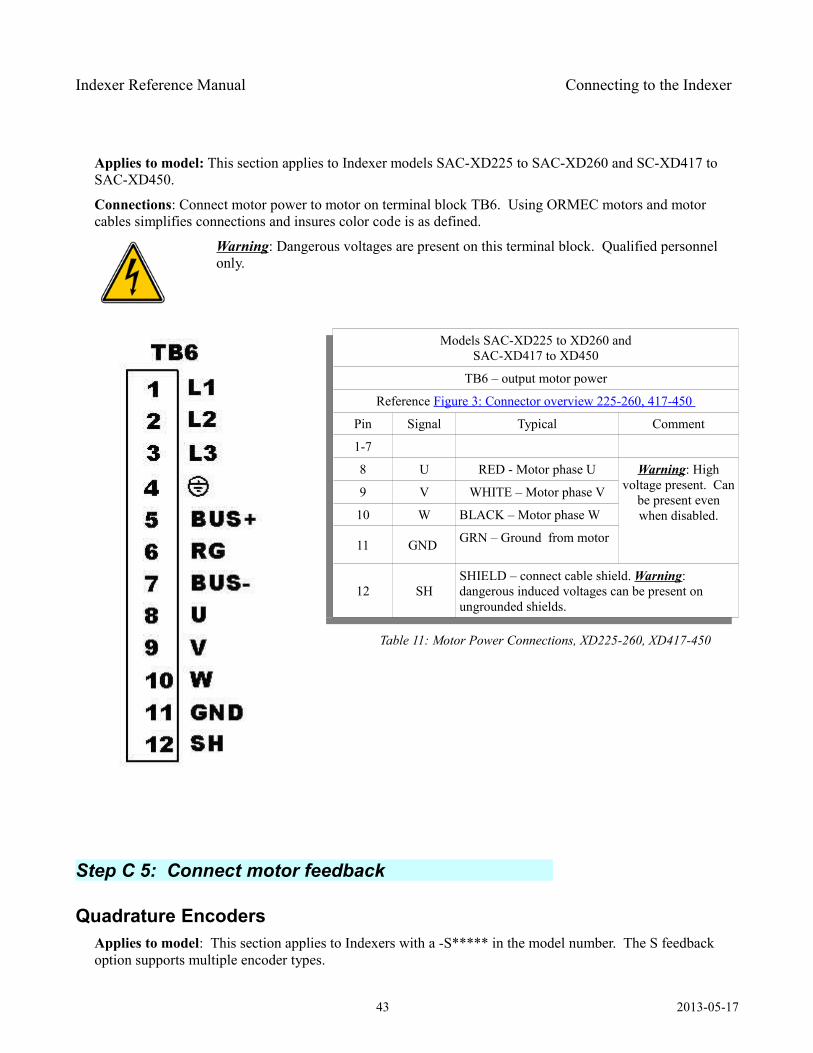
Indexer Reference Manual Connecting to the Indexer
Applies to model: This section applies to Indexer models SAC-XD225 to SAC-XD260 and SC-XD417 to SAC-XD450.
Connections: Connect motor power to motor on terminal block TB6. Using ORMEC motors and motor cables simplifies connections and insures color code is as defined.
Warning: Dangerous voltages are present on this terminal block. Qualified personnel only.
Models SAC-XD225 to XD260 andSAC-XD417 to XD450
TB6 – output motor power
Reference Figure 3: Connector overview 225-260, 417-450
Pin Signal Typical Comment
1-7
8 U RED - Motor phase U Warning: High voltage present. Can
be present even when disabled.
9 V WHITE – Motor phase V
10 W BLACK – Motor phase W
11 GND GRN – Ground from motor
12 SHSHIELD – connect cable shield. Warning: dangerous induced voltages can be present on ungrounded shields.
Table 11: Motor Power Connections, XD225-260, XD417-450
Step C 5: Connect motor feedback
Quadrature EncodersApplies to model: This section applies to Indexers with a -S***** in the model number. The S feedback option supports multiple encoder types.
43 2013-05-17
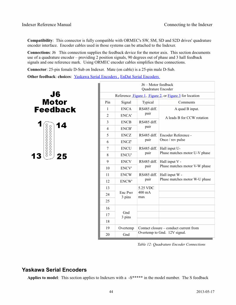
Indexer Reference Manual Connecting to the Indexer
Compatibility: This connector is fully compatible with ORMEC's SW, SM, SD and S2D drives' quadrature encoder interface. Encoder cables used in those systems can be attached to the Indexer.
Connections: J6 This connection supplies the feedback device for the motor axis. This section documents use of a quadrature encoder – providing 2 position signals, 90 degrees out of phase and 3 hall feedback signals and one reference mark. Using ORMEC encoder cables simplifies these connections.
Connector: 25-pin female D-Sub on Indexer. Mate (on cable) is a 25-pin male D-Sub.
Other feedback: choices: Yaskawa Serial Encoders , EnDat Serial Encoders
J6 – Motor feedbackQuadrature Encoder
Reference Figure 1, Figure 2, or Figure 3 for location
Pin Signal Typical Comments
1 ENCA RS485 diff. pair
A quad B input.
A leads B for CCW rotation2 ENCA'
3 ENCB RS485 diff. pair4 ENCB'
5 ENCZ RS485 diff. pair
Encoder Reference -Once / rev pulse6 ENCZ'
7 ENCU RS485 diff. pair
Hall input U-Phase matches motor U-V phase8 ENCU'
9 ENCV RS485 diff. pair
Hall input V -Phase matches motor V-W phase10 ENCV'
11 ENCW RS485 diff. pair
Hall input W -Phase matches motor W-U phase12 ENCW'
13Enc Pwr3 pins
5.25 VDC400 mA max24
25
16Gnd
3 pins17
18
19 Overtemp Contact closure – conduct current from Overtemp to Gnd. 12V signal.20 Gnd
Table 12: Quadrature Encoder Connections
Yaskawa Serial Encoders Applies to model: This section applies to Indexers with a -S***** in the model number. The S feedback
44 2013-05-17
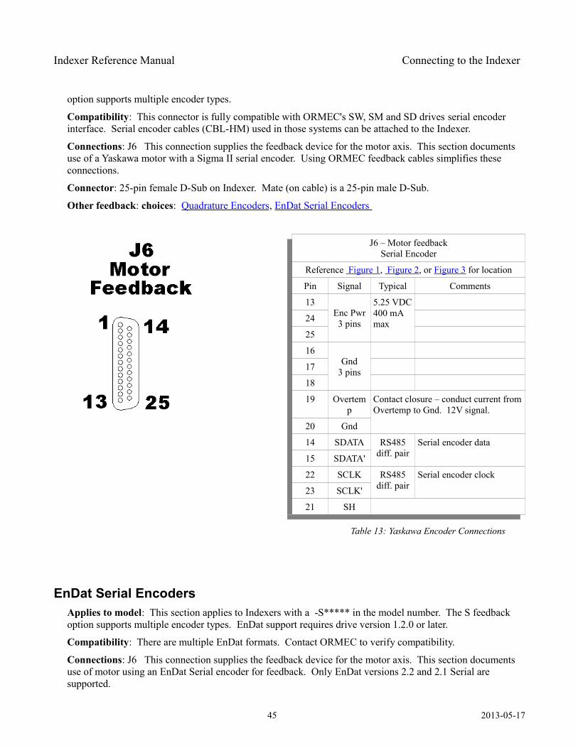
Indexer Reference Manual Connecting to the Indexer
option supports multiple encoder types.
Compatibility: This connector is fully compatible with ORMEC's SW, SM and SD drives serial encoder interface. Serial encoder cables (CBL-HM) used in those systems can be attached to the Indexer.
Connections: J6 This connection supplies the feedback device for the motor axis. This section documents use of a Yaskawa motor with a Sigma II serial encoder. Using ORMEC feedback cables simplifies these connections.
Connector: 25-pin female D-Sub on Indexer. Mate (on cable) is a 25-pin male D-Sub.
Other feedback: choices: Quadrature Encoders, EnDat Serial Encoders
J6 – Motor feedbackSerial Encoder
Reference Figure 1, Figure 2, or Figure 3 for location
Pin Signal Typical Comments
13Enc Pwr3 pins
5.25 VDC400 mA max24
25
16Gnd
3 pins17
18
19 Overtemp
Contact closure – conduct current from Overtemp to Gnd. 12V signal.
20 Gnd
14 SDATA RS485 diff. pair
Serial encoder data
15 SDATA'
22 SCLK RS485 diff. pair
Serial encoder clock
23 SCLK'
21 SH
Table 13: Yaskawa Encoder Connections
EnDat Serial Encoders Applies to model: This section applies to Indexers with a -S***** in the model number. The S feedback option supports multiple encoder types. EnDat support requires drive version 1.2.0 or later.
Compatibility: There are multiple EnDat formats. Contact ORMEC to verify compatibility.
Connections: J6 This connection supplies the feedback device for the motor axis. This section documents use of motor using an EnDat Serial encoder for feedback. Only EnDat versions 2.2 and 2.1 Serial are supported.
45 2013-05-17
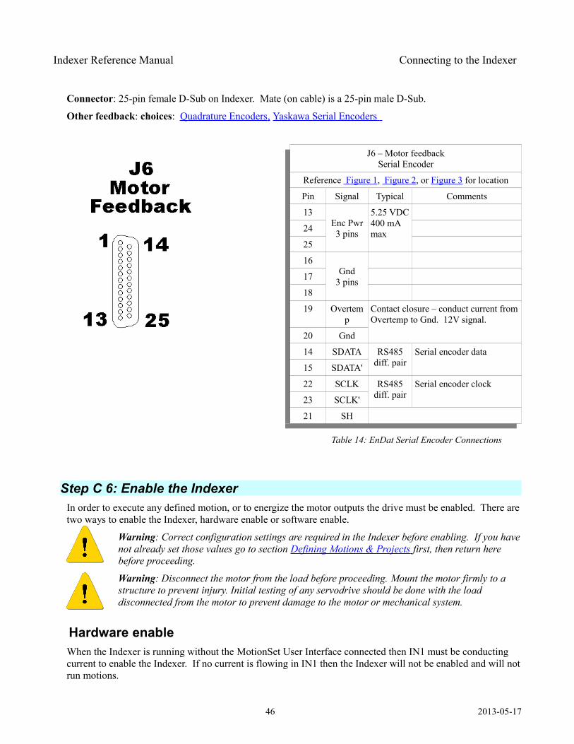
Indexer Reference Manual Connecting to the Indexer
Connector: 25-pin female D-Sub on Indexer. Mate (on cable) is a 25-pin male D-Sub.
Other feedback: choices: Quadrature Encoders , Yaskawa Serial Encoders
J6 – Motor feedbackSerial Encoder
Reference Figure 1, Figure 2, or Figure 3 for location
Pin Signal Typical Comments
13Enc Pwr3 pins
5.25 VDC400 mA max24
25
16Gnd
3 pins17
18
19 Overtemp
Contact closure – conduct current from Overtemp to Gnd. 12V signal.
20 Gnd
14 SDATA RS485 diff. pair
Serial encoder data
15 SDATA'
22 SCLK RS485 diff. pair
Serial encoder clock
23 SCLK'
21 SH
Table 14: EnDat Serial Encoder Connections
Step C 6: Enable the Indexer In order to execute any defined motion, or to energize the motor outputs the drive must be enabled. There are two ways to enable the Indexer, hardware enable or software enable.
Warning: Correct configuration settings are required in the Indexer before enabling. If you have not already set those values go to section Defining Motions & Projects first, then return here before proceeding.
Warning: Disconnect the motor from the load before proceeding. Mount the motor firmly to a structure to prevent injury. Initial testing of any servodrive should be done with the load disconnected from the motor to prevent damage to the motor or mechanical system.
Hardware enableWhen the Indexer is running without the MotionSet User Interface connected then IN1 must be conducting current to enable the Indexer. If no current is flowing in IN1 then the Indexer will not be enabled and will not run motions.
46 2013-05-17
Indexer Reference Manual Connecting to the Indexer
To configure IN1 for use with a sinking current device (e.g. switch or NPN output) connect the positive side of your I/O power supply (e.g. 24v) to pin 5 of J4. Connect the high side of your enable switch or device to pin 1 of connector J4. Connect the other side of your enable switch to ground of your I/O power supply.
To configure IN1 for use with a sourcing current device (e.g. switch or PNP output) connect the negative side of your I/O power supply (e.g. ground) to pin 5 of J4. Connect the high side of your enable switch or device to the positive side of your I/O power supply (e.g. 24v). Connect the other side of your enable switch to pin 1 of connector J4.
MotionSet - Software enableWhen the MotionSet User interface is connected to the Indexer then the hardware enable on IN1 can be overridden. Open the I/O exerciser by clicking on the ICON.
Once open the left column of indicators can control the inputs. By default the hardware remains in control of the input, which is the safest mode of operation. The hardware input can be overridden by the I/O exerciser. This can be selected on a point by point basis. A check box to the left of each input selects and indicates which are overridden. At the top of the column is a quick select to override all inputs.
Using the mouse to control I/O points:
Left mouse button – momentary enable – while you press and hold the I/O point is forced on. When you let go it goes off.
Right mouse button– latches I/O point on. Stays on until you click on it again (left or right click).
To Enable the Indexer for motion use IN1 – Enable. Enable is fixed to IN1 and is the only fixed I/O point. Right mouse click on IN1 to latch the drive enabled.
Step C 7: Connecting I/O points Applies to model: This section applies to all Indexers. Indexer I/O provides access to the many I/O functions built into the Indexer.
Connector: 37-pin female D-Sub on Indexer. Mate (on cable) is a 37-pin male D-Sub.
Connections: Indexer I/O is provided at connector J4.
Function: The I/O points can be software configured to perform a large number of functions. The functions and complete documentation can be found in MotionSet and the on-line Help. A summary of the functions can be found following the hardware definition or by following this link to the I/O function table.
Inputs: The Indexer comes standard with 14 optically coupled inputs, 12 standard and 2 high speed. The standard inputs are configured in three groups of 4. Each group can be hardware configured to interface to sinking or sourcing type inputs. Configuration is accomplished by wiring, no software settings are required.
The inputs operate by conducting current. When input current is 0 the input is off. When input current is above the minimum the input is on. When the software is configured for edge operation a “rising” edge is the transition from Off to On. That is from no current to current on. It does not matter whether the input is configured for sinking or sourcing.
Details of the I/O connector pinouts are listed in Table 15: I/O Input Connections
47 2013-05-17
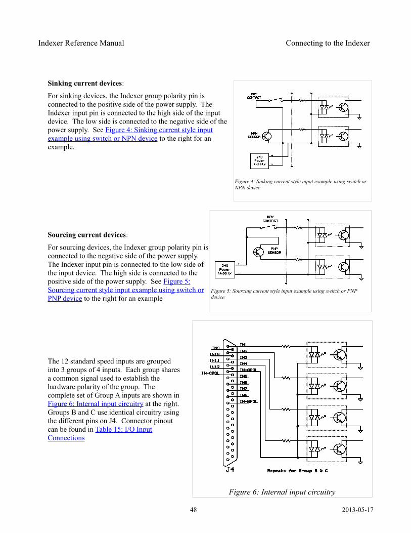
Indexer Reference Manual Connecting to the Indexer
Sinking current devices:
For sinking devices, the Indexer group polarity pin is connected to the positive side of the power supply. The Indexer input pin is connected to the high side of the input device. The low side is connected to the negative side of the power supply. See Figure 4: Sinking current style inputexample using switch or NPN device to the right for an example.
Sourcing current devices:
For sourcing devices, the Indexer group polarity pin is connected to the negative side of the power supply. The Indexer input pin is connected to the low side of the input device. The high side is connected to the positive side of the power supply. See Figure 5:Sourcing current style input example using switch orPNP device to the right for an example
The 12 standard speed inputs are grouped into 3 groups of 4 inputs. Each group shares a common signal used to establish the hardware polarity of the group. The complete set of Group A inputs are shown in Figure 6: Internal input circuitry at the right. Groups B and C use identical circuitry using the different pins on J4. Connector pinout can be found in Table 15: I/O InputConnections
48 2013-05-17
Figure 6: Internal input circuitry
Figure 5: Sourcing current style input example using switch or PNP device
Figure 4: Sinking current style input example using switch or NPN device
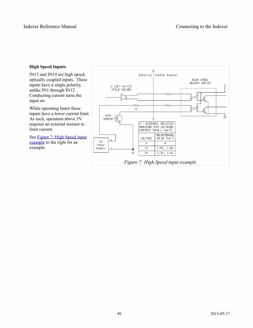
Indexer Reference Manual Connecting to the Indexer
High Speed Inputs:
IN13 and IN14 are high speed, optically coupled inputs. These inputs have a single polarity, unlike IN1 through IN12. Conducting current turns the input on.
While operating faster these inputs have a lower current limit. As such, operation above 5V requires an external resistor to limit current.
See Figure 7: High Speed inputexample to the right for an example.
49 2013-05-17
Figure 7: High Speed input example
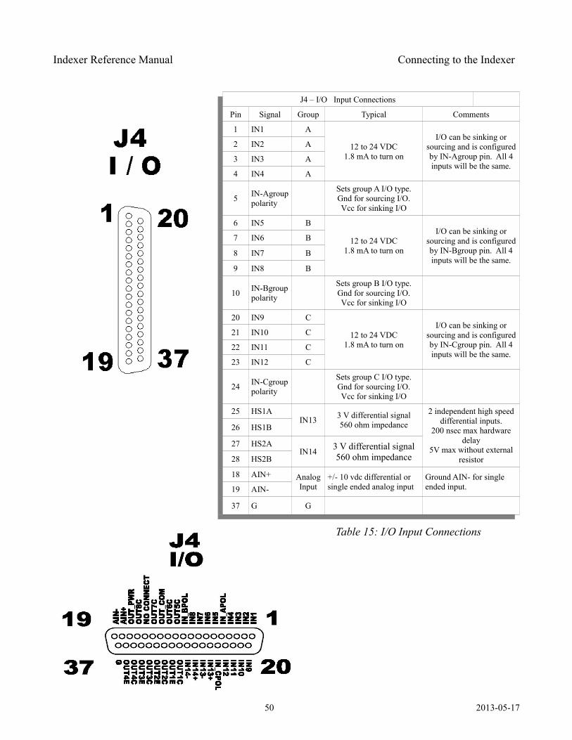
Indexer Reference Manual Connecting to the Indexer
J4 – I/O Input Connections
Pin Signal Group Typical Comments
1 IN1 A
12 to 24 VDC1.8 mA to turn on
I/O can be sinking or sourcing and is configured by IN-Agroup pin. All 4 inputs will be the same.
2 IN2 A
3 IN3 A
4 IN4 A
5 IN-Agroup polarity
Sets group A I/O type.Gnd for sourcing I/O.Vcc for sinking I/O
6 IN5 B
12 to 24 VDC1.8 mA to turn on
I/O can be sinking or sourcing and is configured by IN-Bgroup pin. All 4 inputs will be the same.
7 IN6 B
8 IN7 B
9 IN8 B
10 IN-Bgroup polarity
Sets group B I/O type.Gnd for sourcing I/O.Vcc for sinking I/O
20 IN9 C
12 to 24 VDC1.8 mA to turn on
I/O can be sinking or sourcing and is configured by IN-Cgroup pin. All 4 inputs will be the same.
21 IN10 C
22 IN11 C
23 IN12 C
24 IN-Cgroup polarity
Sets group C I/O type.Gnd for sourcing I/O.Vcc for sinking I/O
25 HS1AIN13 3 V differential signal
560 ohm impedance2 independent high speed
differential inputs.200 nsec max hardware
delay5V max without external
resistor
26 HS1B
27 HS2AIN14 3 V differential signal
560 ohm impedance28 HS2B
18 AIN+ Analog Input
+/- 10 vdc differential or single ended analog input
Ground AIN- for single ended input.19 AIN-
37 G G
Table 15: I/O Input Connections
50 2013-05-17
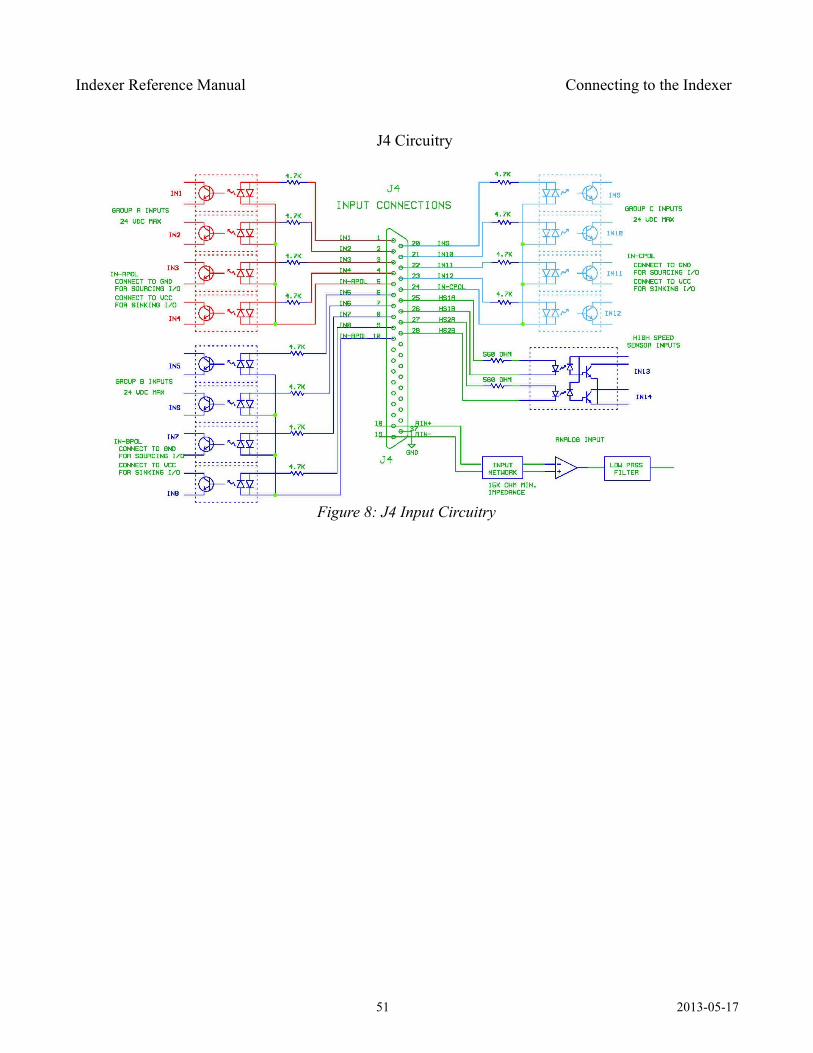
Indexer Reference Manual Connecting to the Indexer
J4 Circuitry
51 2013-05-17
Figure 8: J4 Input Circuitry
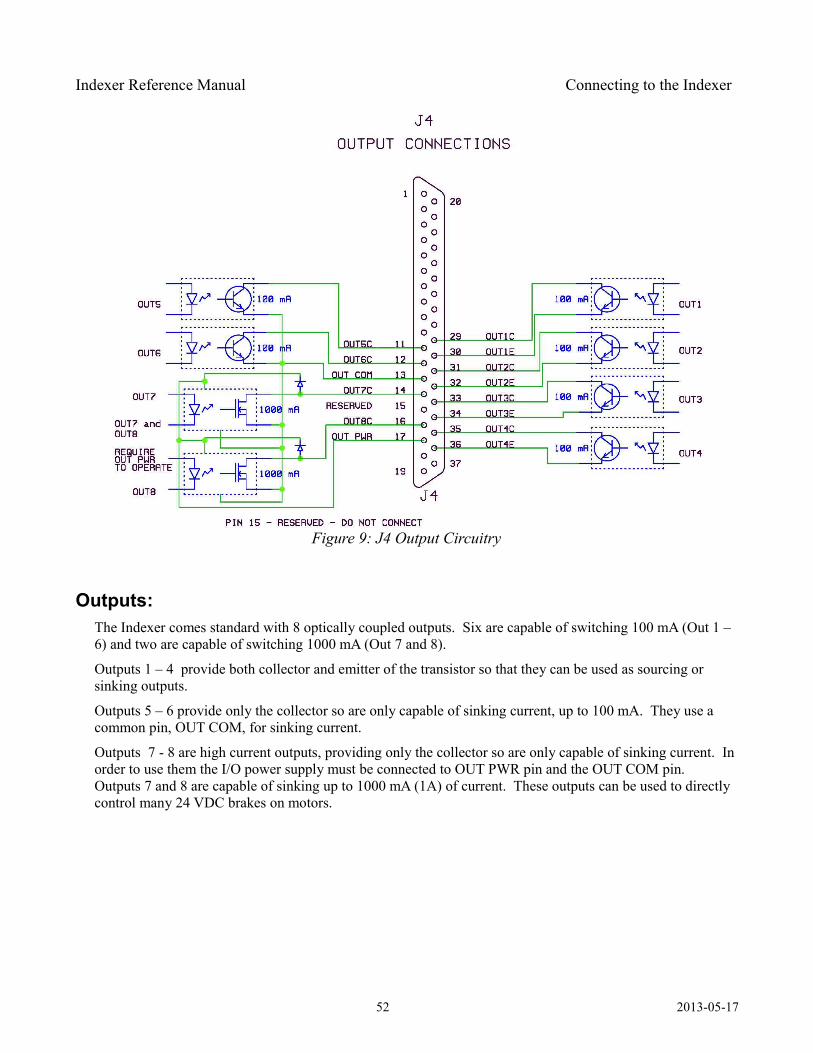
Indexer Reference Manual Connecting to the Indexer
Outputs: The Indexer comes standard with 8 optically coupled outputs. Six are capable of switching 100 mA (Out 1 – 6) and two are capable of switching 1000 mA (Out 7 and 8).
Outputs 1 – 4 provide both collector and emitter of the transistor so that they can be used as sourcing or sinking outputs.
Outputs 5 – 6 provide only the collector so are only capable of sinking current, up to 100 mA. They use a common pin, OUT COM, for sinking current.
Outputs 7 - 8 are high current outputs, providing only the collector so are only capable of sinking current. In order to use them the I/O power supply must be connected to OUT PWR pin and the OUT COM pin. Outputs 7 and 8 are capable of sinking up to 1000 mA (1A) of current. These outputs can be used to directly control many 24 VDC brakes on motors.
52 2013-05-17
Figure 9: J4 Output Circuitry
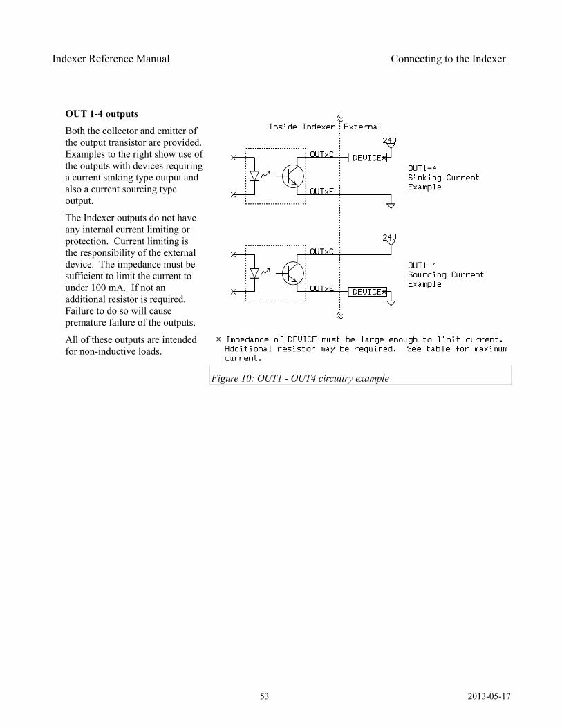
Indexer Reference Manual Connecting to the Indexer
OUT 1-4 outputs
Both the collector and emitter of the output transistor are provided. Examples to the right show use of the outputs with devices requiring a current sinking type output and also a current sourcing type output.
The Indexer outputs do not have any internal current limiting or protection. Current limiting is the responsibility of the external device. The impedance must be sufficient to limit the current to under 100 mA. If not an additional resistor is required. Failure to do so will cause premature failure of the outputs.
All of these outputs are intended for non-inductive loads.
53 2013-05-17
Figure 10: OUT1 - OUT4 circuitry example
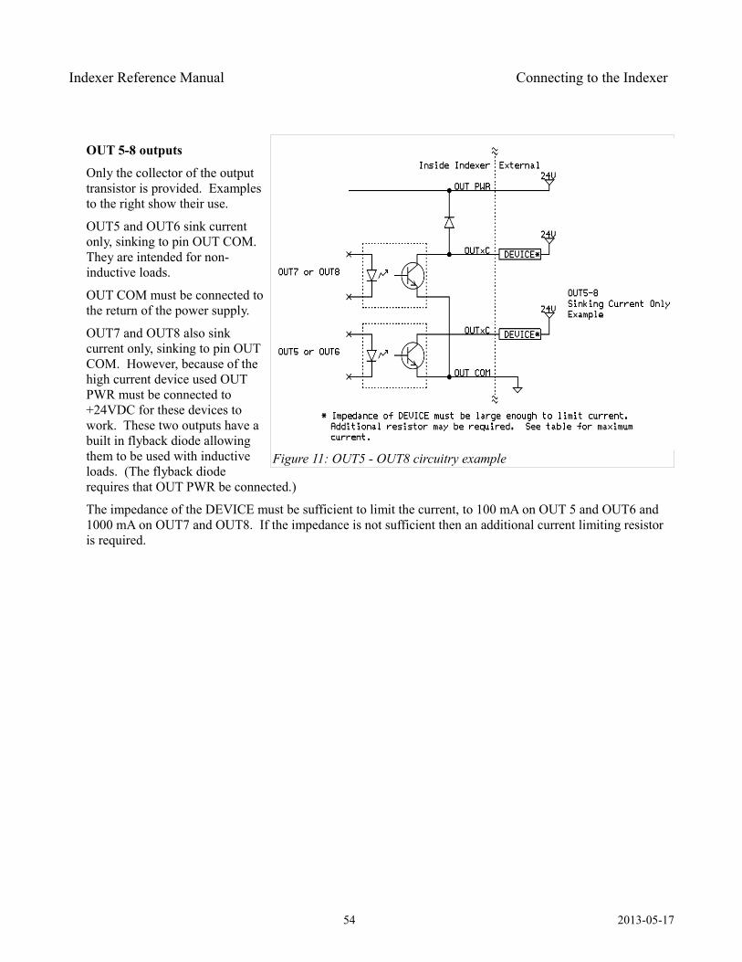
Indexer Reference Manual Connecting to the Indexer
OUT 5-8 outputs
Only the collector of the output transistor is provided. Examples to the right show their use.
OUT5 and OUT6 sink current only, sinking to pin OUT COM. They are intended for non-inductive loads.
OUT COM must be connected to the return of the power supply.
OUT7 and OUT8 also sink current only, sinking to pin OUT COM. However, because of the high current device used OUT PWR must be connected to +24VDC for these devices to work. These two outputs have a built in flyback diode allowing them to be used with inductive loads. (The flyback diode requires that OUT PWR be connected.)
The impedance of the DEVICE must be sufficient to limit the current, to 100 mA on OUT 5 and OUT6 and 1000 mA on OUT7 and OUT8. If the impedance is not sufficient then an additional current limiting resistor is required.
54 2013-05-17
Figure 11: OUT5 - OUT8 circuitry example
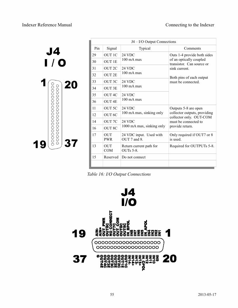
Indexer Reference Manual Connecting to the Indexer
J4 – I/O Output Connections
Pin Signal Typical Comments
29 OUT 1C 24 VDC100 mA max
Outs 1-4 provide both sides of an optically coupled transistor. Can source or sink current.
Both pins of each output must be connected.
30 OUT 1E
31 OUT 2C 24 VDC100 mA max32 OUT 2E
33 OUT 3C 24 VDC100 mA max34 OUT 3E
35 OUT 4C 24 VDC100 mA max36 OUT 4E
11 OUT 5C 24 VDC100 mA max, sinking only
Outputs 5-8 are open collector outputs, providing collector only. OUT-COM must be connected to provide return.
12 OUT 6C
14 OUT 7C 24 VDC1000 mA max, sinking only16 OUT 8C
17 OUT PWR
24 VDC input. Used with OUT 7 and 8.
Only required if OUT7 or 8 is used.
13 OUT COM
Return current path for OUTs 5-8.
Required for OUTPUTs 5-8.
15 Reserved Do not connect
Table 16: I/O Output Connections
55 2013-05-17
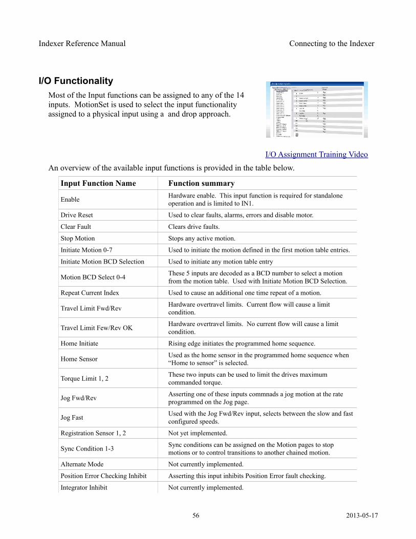
Indexer Reference Manual Connecting to the Indexer
I/O FunctionalityMost of the Input functions can be assigned to any of the 14 inputs. MotionSet is used to select the input functionality assigned to a physical input using a and drop approach.
I/O Assignment Training Video
An overview of the available input functions is provided in the table below.
Input Function Name Function summary
Enable Hardware enable. This input function is required for standalone operation and is limited to IN1.
Drive Reset Used to clear faults, alarms, errors and disable motor.
Clear Fault Clears drive faults.
Stop Motion Stops any active motion.
Initiate Motion 0-7 Used to initiate the motion defined in the first motion table entries.
Initiate Motion BCD Selection Used to initiate any motion table entry
Motion BCD Select 0-4 These 5 inputs are decoded as a BCD number to select a motion from the motion table. Used with Initiate Motion BCD Selection.
Repeat Current Index Used to cause an additional one time repeat of a motion.
Travel Limit Fwd/Rev Hardware overtravel limits. Current flow will cause a limit condition.
Travel Limit Few/Rev OK Hardware overtravel limits. No current flow will cause a limit condition.
Home Initiate Rising edge initiates the programmed home sequence.
Home Sensor Used as the home sensor in the programmed home sequence when “Home to sensor” is selected.
Torque Limit 1, 2 These two inputs can be used to limit the drives maximum commanded torque.
Jog Fwd/Rev Asserting one of these inputs commnads a jog motion at the rate programmed on the Jog page.
Jog Fast Used with the Jog Fwd/Rev input, selects between the slow and fast configured speeds.
Registration Sensor 1, 2 Not yet implemented.
Sync Condition 1-3 Sync conditions can be assigned on the Motion pages to stop motions or to control transitions to another chained motion.
Alternate Mode Not currently implemented.
Position Error Checking Inhibit Asserting this input inhibits Position Error fault checking.
Integrator Inhibit Not currently implemented.
56 2013-05-17
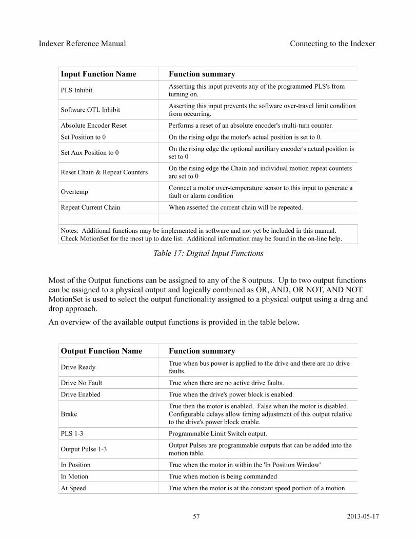
Indexer Reference Manual Connecting to the Indexer
Input Function Name Function summary
PLS Inhibit Asserting this input prevents any of the programmed PLS's from turning on.
Software OTL Inhibit Asserting this input prevents the software over-travel limit condition from occurring.
Absolute Encoder Reset Performs a reset of an absolute encoder's multi-turn counter.
Set Position to 0 On the rising edge the motor's actual position is set to 0.
Set Aux Position to 0 On the rising edge the optional auxiliary encoder's actual position is set to 0
Reset Chain & Repeat Counters On the rising edge the Chain and individual motion repeat counters are set to 0
Overtemp Connect a motor over-temperature sensor to this input to generate a fault or alarm condition
Repeat Current Chain When asserted the current chain will be repeated.
Notes: Additional functions may be implemented in software and not yet be included in this manual. Check MotionSet for the most up to date list. Additional information may be found in the on-line help.
Table 17: Digital Input Functions
Most of the Output functions can be assigned to any of the 8 outputs. Up to two output functions can be assigned to a physical output and logically combined as OR, AND, OR NOT, AND NOT. MotionSet is used to select the output functionality assigned to a physical output using a drag and drop approach.
An overview of the available output functions is provided in the table below.
Output Function Name Function summary
Drive Ready True when bus power is applied to the drive and there are no drive faults.
Drive No Fault True when there are no active drive faults.
Drive Enabled True when the drive's power block is enabled.
BrakeTrue then the motor is enabled. False when the motor is disabled. Configurable delays allow timing adjustment of this output relative to the drive's power block enable.
PLS 1-3 Programmable Limit Switch output.
Output Pulse 1-3 Output Pulses are programmable outputs that can be added into the motion table.
In Position True when the motor in within the 'In Position Window'
In Motion True when motion is being commanded
At Speed True when the motor is at the constant speed portion of a motion
57 2013-05-17
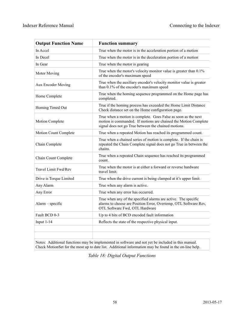
Indexer Reference Manual Connecting to the Indexer
Output Function Name Function summaryIn Accel True when the motor is in the acceleration portion of a motion
In Decel True when the motor is in the deceleration portion of a motion
In Gear True when the motor is gearing
Motor Moving True when the motor's velocity monitor value is greater than 0.1% of the encoder's maximum speed
Aux Encoder Moving True when the auxiliary encoder's velocity monitor value is greater than 0.1% of the encoder's maximum speed
Home Complete True when the homing sequence programmed on the Home page has completed.
Homing Timed Out True if the homing process has exceeded the Home Limit Distance Check distance set on the Home configuration page.
Motion CompleteTrue when a motion is complete. Goes False as soon as the next motion is commanded. If motions are chained the Motion Complete signal does not go True between the chained motions.
Motion Count Complete True when a repeated Motion has reached its programmed count.
Chain CompleteTrue when a chained series of motion is complete. If the chain is repeated the Chain Complete signal does not go True in between the chains.
Chain Count Complete True when a repeated Chain sequence has reached its programmed count.
Travel Limit Fwd/Rev True when the motor is at either a forward or reverse hardware travel limit.
Drive is Torque Limited True when the drive current is being clamped at it’s upper limit.
Any Alarm True when any alarm is active.
Any Error True when any error has occurred.
Alarm – specificTrue when any of the specified alarms are active. The specific alarms to choose are Position Error, Overtemp, OTL Software Rev, OTL Software Fwd, OTL Hardware
Fault BCD 0-3 Up to 4 bits of BCD encoded fault information
Input 1-14 Reflects the state of the respective physical input.
Notes: Additional functions may be implemented in software and not yet be included in this manual. Check MotionSet for the most up to date list. Additional information may be found in the on-line help.
Table 18: Digital Output Functions
58 2013-05-17
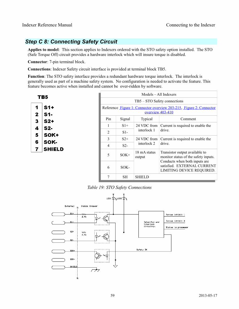
Indexer Reference Manual Connecting to the Indexer
Step C 8: Connecting Safety Circuit Applies to model: This section applies to Indexers ordered with the STO safety option installed. The STO (Safe Torque Off) circuit provides a hardware interlock which will insure torque is disabled.
Connector: 7-pin terminal block.
Connections: Indexer Safety circuit interface is provided at terminal block TB5.
Function: The STO safety interface provides a redundant hardware torque interlock. The interlock is generally used as part of a machine safety system. No configuration is needed to activate the feature. This feature becomes active when installed and cannot be over-ridden by software.
Models – All Indexers
TB5 – STO Safety connections
Reference Figure 1: Connector overview 203-215, Figure 2: Connectoroverview 403-410
Pin Signal Typical Comment
1 S1+ 24 VDC from interlock 1
Current is required to enable the drive.2 S1-
3 S2+ 24 VDC from interlock 2
Current is required to enable the drive.4 S2-
5 SOK+18 mA status output
Transistor output available to monitor status of the safety inputs. Conducts when both inputs are satisfied. EXTERNAL CURRENT LIMITING DEVICE REQUIRED.
6 SOK-
7 SH SHIELD
Table 19: STO Safety Connections
59 2013-05-17

Indexer Reference Manual Defining Motions & Projects
Defining Motions & Projects
Step D 1: Open commissioning tool – MotionSet ORMEC provides a fully integrated commissioning tool, called MotionSet.
With MotionSet you:
1) define which motor is attached to the Indexer,
2) what motions should be done,
3) send (download) those definitions to the Indexer,
4) monitor activity on the Indexer,
MotionSet is a software GUI (Graphical User Interface) which must be installed on your computer to use it. With it you will be able to define projects and communicate with the Indexer. The software is found on the ORMEC website at http://www.ormec.com/Products/ Software / MotionSet .aspx . If you haven't already installed MotionSet please do so at this time.
First – start MotionSet: Find the ICON on your desktop and double click to start. (Or find it in the ORMEC Systems Corp program group.
Below is a written, step by step guide to configuring your system. A video of this process is also available at Project Setup.
Step D 2: Start your project Once in MotionSet expand Setup (click on +). Once open you will need to work down the list, selecting and defining as you go. The project screen will allow you to enter a description and revision to identify the
60 2013-05-17

Indexer Reference Manual Defining Motions & Projects
project, select units and change the Ethernet address if necessary.
Once open review each item on the right, changing those which are not correct.
Entry Meaning / CommentDescription A saved description to aid in keeping track of projects. This item is
recommended, but not required.
Revision Support to aid in tracking revisions and variations. This item is recommended, but not required.
Error Handling and Reporting Faults are defined as conditions which prevent operation of the Indexer. Faults are situations or failures which may result in equipment or personnel damage. Because of the safety nature all Faults cause the Indexer to disable the motor.Error are conditions which are not correct but which are less severe than a Fault. Errors will likely cause an error in the application motion but are not a safety risk.By default errors are reported but do not disable the Indexer. Checking the box will cause Errors to be handled the same as Faults, that is disabling the Indexer when they happen.
Drive Real Time Clock The Indexer has a built in real time clock. It is used to time stamp entries in the event log and for general information. This box controls the time source for setting the clock on the Indexer. Note, the Indexer has a built in short term clock backup power. When turned off the Real Time Clock will remain accurate for about 24 hours. After that it will need to be reset if an accurate date and time is desired.
Table 20: Project Setup Item explanation
Step D 3: Select your drive
61 2013-05-17
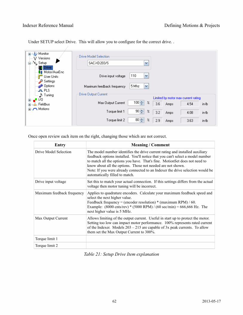
Indexer Reference Manual Defining Motions & Projects
Under SETUP select Drive. This will allow you to configure for the correct drive. .
Once open review each item on the right, changing those which are not correct.
Entry Meaning / CommentDrive Model Selection The model number identifies the drive current rating and installed auxiliary
feedback options installed. You'll notice that you can't select a model number to match all the options you have. That's fine. MotionSet does not need to know about all the options. Those not needed are not shown.Note: If you were already connected to an Indexer the drive selection would be automatically filled to match.
Drive input voltage Set this to match your actual connection. If this settings differs from the actual voltage then motor tuning will be incorrect.
Maximum feedback frequency Applies to quadrature encoders. Calculate your maximum feedback speed and select the next higher value. Feedback frequency = (encoder resolution) * (maximum RPM) / 60.Example: (8000 cnts/rev) * (5000 RPM) / (60 sec/min) = 666,666 Hz. The next higher value is 5 MHz.
Max Output Current Allows limiting of the output current. Useful in start up to protect the motor. Setting too low can impact motor performance. 100% represents rated current of the Indexer. Models 203 – 215 are capable of 3x peak currents. To allow them set the Max Output Current to 300%.
Torque limit 1
Torque limit 2
Table 21: Setup Drive Item explanation
62 2013-05-17
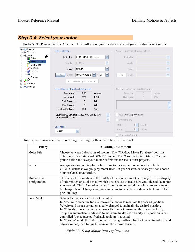
Indexer Reference Manual Defining Motions & Projects
Step D 4: Select your motor Under SETUP select Motor/AuxEnc. This will allow you to select and configure for the correct motor.
Once open review each item on the right, changing those which are not correct.
Entry Meaning / CommentMotor File Choose between 2 databases of motors. The “ORMEC Motor Database” contains
definitions for all standard ORMEC motors. The “Custom Motor Database” allows you to define and save your motor definitions for use in other projects.
Series An organization tool to place a line of motor or similar motors together. In the ORMEC database we group by motor lines. In your custom database you can choose your preferred organization.
Motor/Drive configuration
This table of information in the middle of the screen cannot be changed. It is a display of information about the motor which you can use to make sure you selected the motor you wanted. The information comes from the motor and drive selections and cannot be changed here. Changes are made in the motor selection or drive selections on the previous step.
Loop Mode Selects the highest level of motor control. In “Position” mode the Indexer moves the motor to maintain the desired position. Velocity and torque are automatically changed to maintain the desired position.In “Velocity” mode the Indexer moves the motor to maintain the desired velocity. Torque is automatically adjusted to maintain the desired velocity. The position is not controlled (the connected feedback position is counted).In “Tension” mode the Indexer requires analog feedback from a tension transducer and adjusts velocity and torque to maintain the desired tension.
Table 22: Setup Motor Item explanations
63 2013-05-17
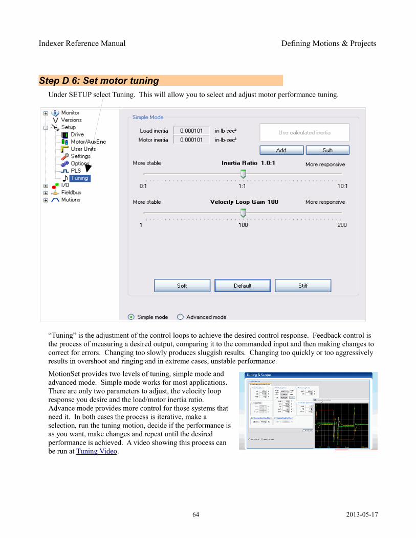
Indexer Reference Manual Defining Motions & Projects
Step D 6: Set motor tuning Under SETUP select Tuning. This will allow you to select and adjust motor performance tuning.
“Tuning” is the adjustment of the control loops to achieve the desired control response. Feedback control is the process of measuring a desired output, comparing it to the commanded input and then making changes to correct for errors. Changing too slowly produces sluggish results. Changing too quickly or too aggressively results in overshoot and ringing and in extreme cases, unstable performance.
MotionSet provides two levels of tuning, simple mode and advanced mode. Simple mode works for most applications. There are only two parameters to adjust, the velocity loop response you desire and the load/motor inertia ratio. Advance mode provides more control for those systems that need it. In both cases the process is iterative, make a selection, run the tuning motion, decide if the performance is as you want, make changes and repeat until the desired performance is achieved. A video showing this process can be run at Tuning Video .
64 2013-05-17
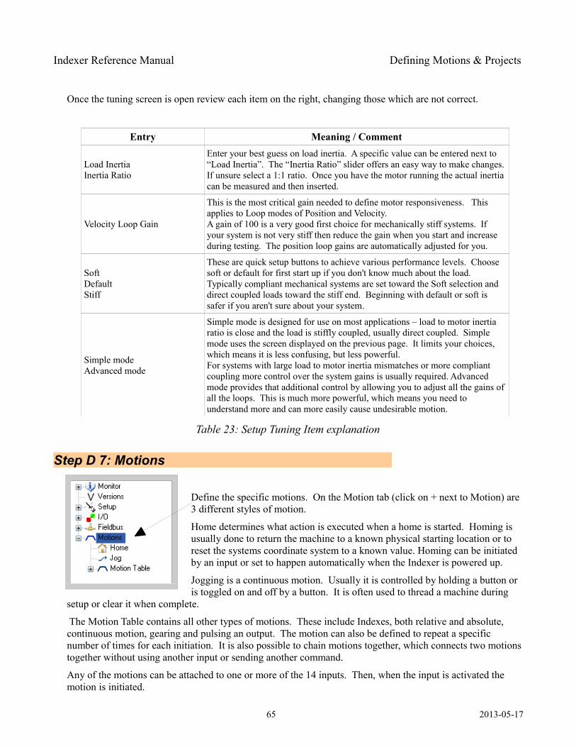
Indexer Reference Manual Defining Motions & Projects
Once the tuning screen is open review each item on the right, changing those which are not correct.
Entry Meaning / Comment
Load InertiaInertia Ratio
Enter your best guess on load inertia. A specific value can be entered next to “Load Inertia”. The “Inertia Ratio” slider offers an easy way to make changes. If unsure select a 1:1 ratio. Once you have the motor running the actual inertia can be measured and then inserted.
Velocity Loop Gain
This is the most critical gain needed to define motor responsiveness. This applies to Loop modes of Position and Velocity. A gain of 100 is a very good first choice for mechanically stiff systems. If your system is not very stiff then reduce the gain when you start and increase during testing. The position loop gains are automatically adjusted for you.
SoftDefaultStiff
These are quick setup buttons to achieve various performance levels. Choose soft or default for first start up if you don't know much about the load. Typically compliant mechanical systems are set toward the Soft selection and direct coupled loads toward the stiff end. Beginning with default or soft is safer if you aren't sure about your system.
Simple modeAdvanced mode
Simple mode is designed for use on most applications – load to motor inertia ratio is close and the load is stiffly coupled, usually direct coupled. Simple mode uses the screen displayed on the previous page. It limits your choices, which means it is less confusing, but less powerful. For systems with large load to motor inertia mismatches or more compliant coupling more control over the system gains is usually required. Advanced mode provides that additional control by allowing you to adjust all the gains of all the loops. This is much more powerful, which means you need to understand more and can more easily cause undesirable motion.
Table 23: Setup Tuning Item explanation
Step D 7: Motions
Define the specific motions. On the Motion tab (click on + next to Motion) are 3 different styles of motion.
Home determines what action is executed when a home is started. Homing is usually done to return the machine to a known physical starting location or to reset the systems coordinate system to a known value. Homing can be initiated by an input or set to happen automatically when the Indexer is powered up.
Jogging is a continuous motion. Usually it is controlled by holding a button or is toggled on and off by a button. It is often used to thread a machine during
setup or clear it when complete.
The Motion Table contains all other types of motions. These include Indexes, both relative and absolute, continuous motion, gearing and pulsing an output. The motion can also be defined to repeat a specific number of times for each initiation. It is also possible to chain motions together, which connects two motions together without using another input or sending another command.
Any of the motions can be attached to one or more of the 14 inputs. Then, when the input is activated the motion is initiated.
65 2013-05-17
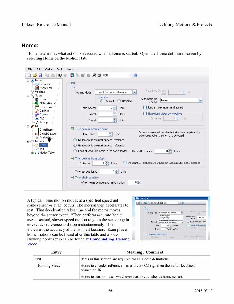
Indexer Reference Manual Defining Motions & Projects
Home: Home determines what action is executed when a home is started. Open the Home definition screen by selecting Home on the Motions tab.
A typical home motion moves at a specified speed until some sensor or event occurs. The motion then decelerates to rest. That deceleration takes time and the motor moves beyond the sensor event. “Then perform accurate home” uses a second, slower speed motion to go to the sensor again or encoder reference and stop instantaneously. This increases the accuracy of the stopped location. Examples of home motions can be found after this table and a video showing home setup can be found at Home and Jog Training Video
Entry Meaning / CommentFirst Items in this section are required for all Home definitions
Homing Mode Home to encoder reference – uses the ENCZ signal on the motor feedback connector, J6
Home to sensor – uses whichever sensor you label as home sensor.
66 2013-05-17
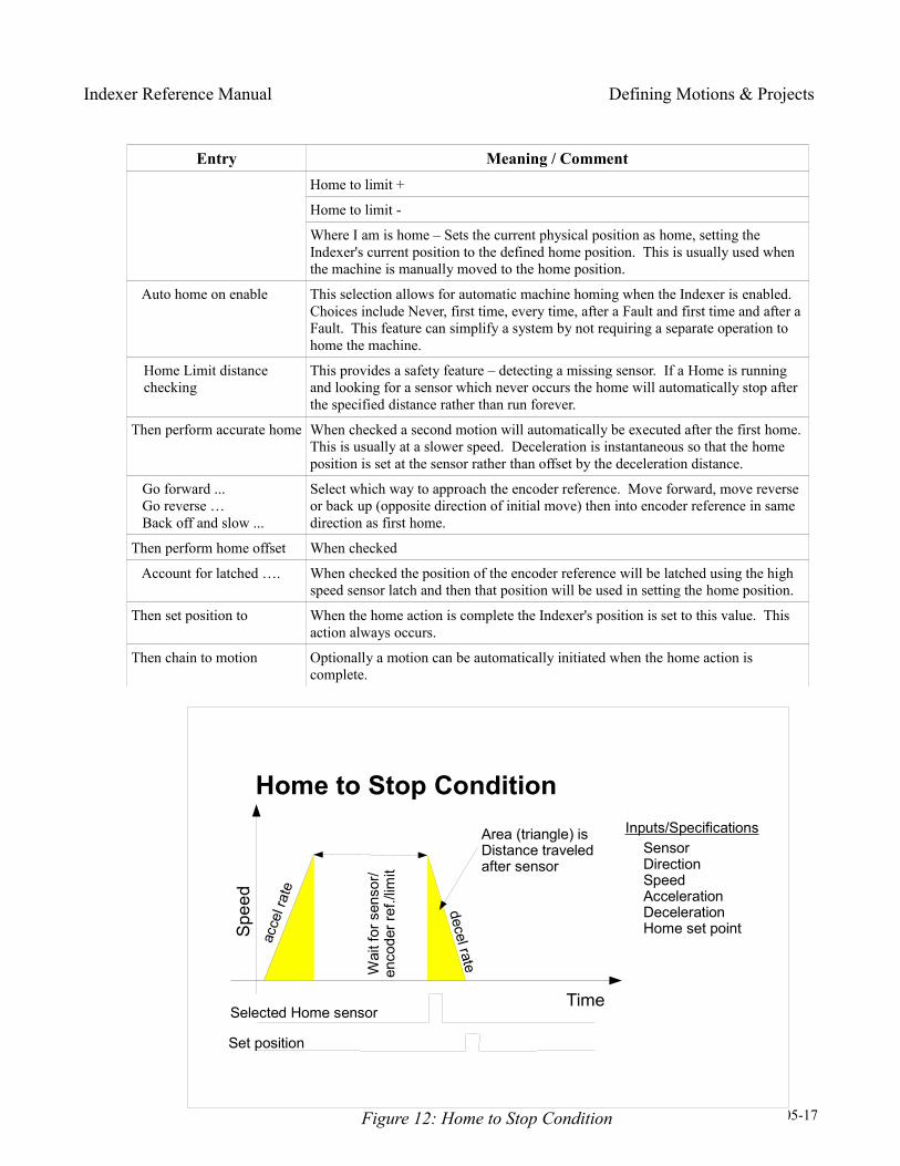
Indexer Reference Manual Defining Motions & Projects
Entry Meaning / CommentHome to limit +
Home to limit -
Where I am is home – Sets the current physical position as home, setting the Indexer's current position to the defined home position. This is usually used when the machine is manually moved to the home position.
Auto home on enable This selection allows for automatic machine homing when the Indexer is enabled. Choices include Never, first time, every time, after a Fault and first time and after a Fault. This feature can simplify a system by not requiring a separate operation to home the machine.
Home Limit distance checking
This provides a safety feature – detecting a missing sensor. If a Home is running and looking for a sensor which never occurs the home will automatically stop after the specified distance rather than run forever.
Then perform accurate home When checked a second motion will automatically be executed after the first home. This is usually at a slower speed. Deceleration is instantaneous so that the home position is set at the sensor rather than offset by the deceleration distance.
Go forward ... Go reverse … Back off and slow ...
Select which way to approach the encoder reference. Move forward, move reverse or back up (opposite direction of initial move) then into encoder reference in same direction as first home.
Then perform home offset When checked
Account for latched …. When checked the position of the encoder reference will be latched using the high speed sensor latch and then that position will be used in setting the home position.
Then set position to When the home action is complete the Indexer's position is set to this value. This action always occurs.
Then chain to motion Optionally a motion can be automatically initiated when the home action is complete.
67 2013-05-17Figure 12: Home to Stop Condition
Home to Stop Condition
Time
Spe
edac
cel r
ate
decel rate
Selected Home sensor
Area (triangle) isDistance traveledafter sensor
Wai
t for
sen
sor/
enco
der r
ef./l
imit
Inputs/SpecificationsSensorDirectionSpeedAccelerationDecelerationHome set point
Set position
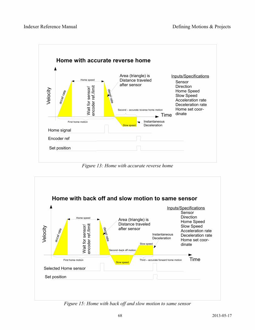
Indexer Reference Manual Defining Motions & Projects
68 2013-05-17
Figure 14: Home with accurate forward home
Home with accurate forward home
Time
Spe
ed
acce
l rat
e
decel rate
Home signal
Area (triangle) isDistance traveledafter sensor
Wai
t for
sen
sor/
enco
der r
ef./l
imit
Inputs/SpecificationsSensorDirectionHome SpeedSlow SpeedAcceleration rateDeceleration rateHome set coor-dinate
Encoder ref
Set position
InstantaneousDecelerationSlow speed
Home speed
First home motion Second – accurate forward home motion
Figure 13: Home with accurate reverse home
Home with accurate reverse home
Time
Velo
city
acce
l rat
e
decel rate
Home signal
Area (triangle) isDistance traveledafter sensor
Wai
t for
sen
sor/
enco
der r
ef./l
imit
Inputs/SpecificationsSensorDirectionHome SpeedSlow SpeedAcceleration rateDeceleration rateHome set coor-dinate
Encoder ref
Set position
InstantaneousDecelerationSlow speed
Home speed
First home motion
Second – accurate reverse home motion
Figure 15: Home with back off and slow motion to same sensor
Home with back off and slow motion to same sensor
Time
Velo
city
acce
l rat
e
decel rate
Selected Home sensor
Area (triangle) isDistance traveledafter sensor
Wai
t for
sen
sor/
enco
der r
ef./l
imit
Inputs/SpecificationsSensorDirectionHome SpeedSlow SpeedAcceleration rateDeceleration rateHome set coor-dinate
Set position
InstantaneousDeceleration
Slow speed
Home speed
First home motion Third – accurate forward home motion
Second–back off motion
Slow speed
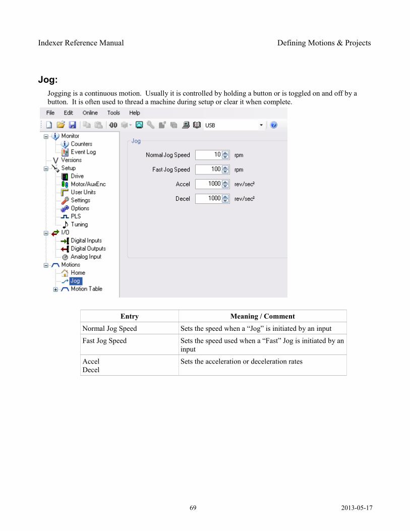
Indexer Reference Manual Defining Motions & Projects
Jog: Jogging is a continuous motion. Usually it is controlled by holding a button or is toggled on and off by a button. It is often used to thread a machine during setup or clear it when complete.
Entry Meaning / CommentNormal Jog Speed Sets the speed when a “Jog” is initiated by an input
Fast Jog Speed Sets the speed used when a “Fast” Jog is initiated by an input
AccelDecel
Sets the acceleration or deceleration rates
69 2013-05-17
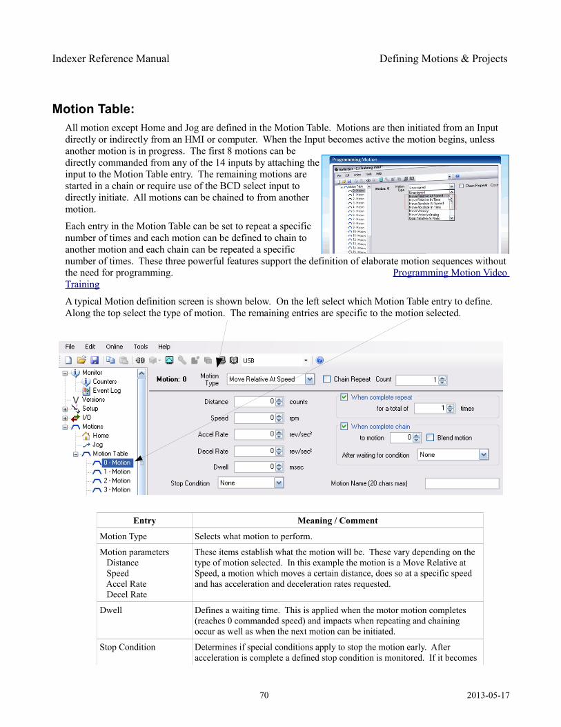
Indexer Reference Manual Defining Motions & Projects
Motion Table: All motion except Home and Jog are defined in the Motion Table. Motions are then initiated from an Input directly or indirectly from an HMI or computer. When the Input becomes active the motion begins, unless another motion is in progress. The first 8 motions can be directly commanded from any of the 14 inputs by attaching the input to the Motion Table entry. The remaining motions are started in a chain or require use of the BCD select input to directly initiate. All motions can be chained to from another motion.
Each entry in the Motion Table can be set to repeat a specific number of times and each motion can be defined to chain to another motion and each chain can be repeated a specific number of times. These three powerful features support the definition of elaborate motion sequences without the need for programming. Programming Motion Video Training
A typical Motion definition screen is shown below. On the left select which Motion Table entry to define. Along the top select the type of motion. The remaining entries are specific to the motion selected.
Entry Meaning / Comment
Motion Type Selects what motion to perform.
Motion parameters Distance Speed Accel Rate Decel Rate
These items establish what the motion will be. These vary depending on the type of motion selected. In this example the motion is a Move Relative at Speed, a motion which moves a certain distance, does so at a specific speed and has acceleration and deceleration rates requested.
Dwell Defines a waiting time. This is applied when the motor motion completes (reaches 0 commanded speed) and impacts when repeating and chaining occur as well as when the next motion can be initiated.
Stop Condition Determines if special conditions apply to stop the motion early. After acceleration is complete a defined stop condition is monitored. If it becomes
70 2013-05-17
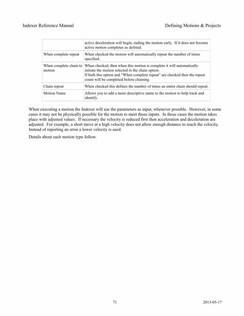
Indexer Reference Manual Defining Motions & Projects
active deceleration will begin, ending the motion early. If it does not become active motion completes as defined.
When complete repeat When checked the motion will automatically repeat the number of times specified.
When complete chain to motion
When checked, then when this motion is complete it will automatically initiate the motion selected in the chain option. If both this option and “When complete repeat” are checked then the repeat count will be completed before chaining.
Chain repeat When checked this defines the number of times an entire chain should repeat.
Motion Name Allows you to add a more descriptive name to the motion to help track and identify.
When executing a motion the Indexer will use the parameters as input, whenever possible. However, in some cases it may not be physically possible for the motion to meet those inputs. In those cases the motion takes place with adjusted values. If necessary the velocity is reduced first then acceleration and deceleration are adjusted. For example, a short move at a high velocity does not allow enough distance to reach the velocity. Instead of reporting an error a lower velocity is used.
Details about each motion type follow.
71 2013-05-17
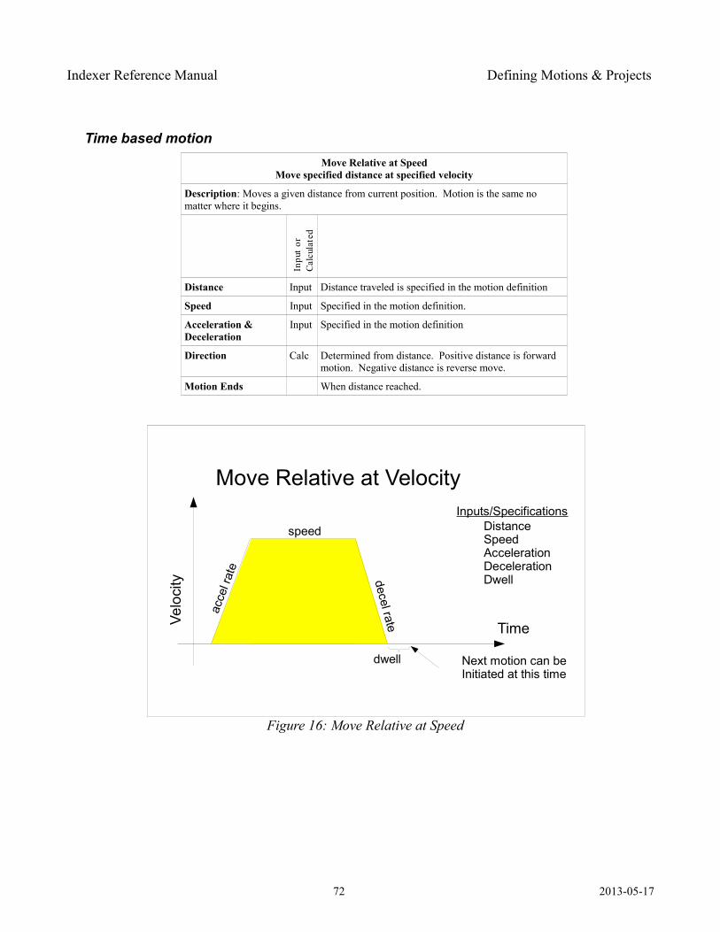
Indexer Reference Manual Defining Motions & Projects
Time based motion Move Relative at Speed
Move specified distance at specified velocity
Description: Moves a given distance from current position. Motion is the same no matter where it begins.
Distance Input Distance traveled is specified in the motion definition
Speed Input Specified in the motion definition.
Acceleration & Deceleration
Input Specified in the motion definition
Direction Calc Determined from distance. Positive distance is forward motion. Negative distance is reverse move.
Motion Ends When distance reached.
72 2013-05-17
Figure 16: Move Relative at Speed
Move Relative at Velocity
TimeVelo
city
acce
l rat
e
decel rate
speedInputs/Specifications
DistanceSpeedAccelerationDecelerationDwell
dwell Next motion can beInitiated at this time
Inpu
t or
Ca
lcul
ated
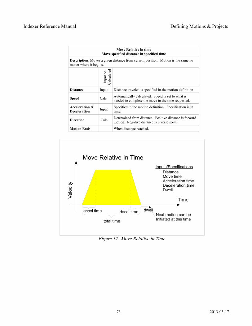
Indexer Reference Manual Defining Motions & Projects
Move Relative in timeMove specified distance in specified time
Description: Moves a given distance from current position. Motion is the same no matter where it begins.
Inpu
t or
Cal
cula
ted
Distance Input Distance traveled is specified in the motion definition
Speed Calc Automatically calculated. Speed is set to what is needed to complete the move in the time requested.
Acceleration & Deceleration Input Specified in the motion definition. Specification is in
time.
Direction Calc Determined from distance. Positive distance is forward motion. Negative distance is reverse move.
Motion Ends When distance reached.
73 2013-05-17
Figure 17: Move Relative in Time
Move Relative In Time
TimeVelo
city
Inputs/SpecificationsDistanceMove timeAcceleration timeDeceleration timeDwell
dwellNext motion can beInitiated at this time
accel time
total time
decel time
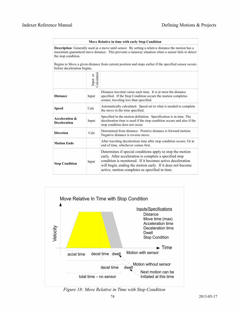
Indexer Reference Manual Defining Motions & Projects
Move Relative in time with early Stop Condition
Description: Generally used as a move until sensor. By setting a relative distance the motion has a maximum guaranteed move distance. This prevents a runaway situation when a sensor fails to detect the stop condition.
Begins to Move a given distance from current position and stops earlier if the specified sensor occurs before deceleration begins.
Inpu
t or
C
alcu
late
dDistance Input
Distance traveled varies each time. It is at most the distance specified. If the Stop Condition occurs the motion completes sooner, traveling less than specified.
Speed Calc Automatically calculated. Speed set to what is needed to complete the move in the time specified.
Acceleration & Deceleration Input
Specified in the motion definition. Specification is in time. The deceleration time is used if the stop condition occurs and also if the stop condition does not occur.
Direction Calc Determined from distance. Positive distance is forward motion. Negative distance is reverse move.
Motion Ends After traveling deceleration time after stop condition occurs. Or at end of time, whichever comes first.
Stop Condition Input
Determines if special conditions apply to stop the motion early. After acceleration is complete a specified stop condition is monitored. If it becomes active deceleration will begin, ending the motion early. If it does not become active, motion completes as specified in time.
74 2013-05-17
Figure 18: Move Relative in Time with Stop Condition
Move Relative In Time with Stop Condition
Time
Velo
city
Inputs/SpecificationsDistanceMove time (max)Acceleration timeDeceleration timeDwellStop Condition
dwell
Next motion can beInitiated at this time
accel time
total time – no sensor
decel time
decel time dwell
Motion with sensor
Motion without sensor
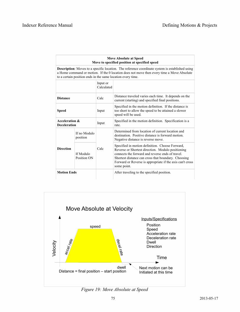
Indexer Reference Manual Defining Motions & Projects
Move Absolute at SpeedMove to specified position at specified speed
Description: Moves to a specific location. The reference coordinate system is established using a Home command or motion. If the 0 location does not move then every time a Move Absolute to a certain position ends in the same location every time.
Input or Calculated
Distance Calc Distance traveled varies each time. It depends on the current (starting) and specified final positions.
Speed InputSpecified in the motion definition. If the distance is too short to allow the speed to be attained a slower speed will be used.
Acceleration & Deceleration Input Specified in the motion definition. Specification is a
rate.
Direction
If no Modulo position
Calc
Determined from location of current location and destination. Positive distance is forward motion. Negative distance is reverse move.
If Modulo Position ON
Specified in motion definition. Choose Forward, Reverse or Shortest direction. Modulo positioning connects the forward and reverse ends of travel. Shortest distance can cross that boundary. Choosing Forward or Reverse is appropriate if the axis can't cross some point.
Motion Ends After traveling to the specified position.
75 2013-05-17
Figure 19: Move Absolute at Speed
Move Absolute at Velocity
TimeVelo
city
acce
l rat
e decel rate
speed
Inputs/SpecificationsPositionSpeedAcceleration rateDeceleration rateDwellDirection
dwell Next motion can beInitiated at this timeDistance = final position – start position
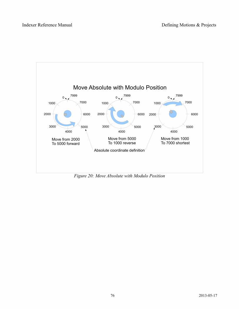
Indexer Reference Manual Defining Motions & Projects
76 2013-05-17
Figure 20: Move Absolute with Modulo Position
Move Absolute with Modulo Position
Absolute coordinate definition
7999
7000
6000
50004000
3000
2000
1000
0 7999
7000
6000
50004000
3000
2000
1000
0 7999
7000
6000
50004000
3000
1000
0
2000
Move from 2000 To 5000 forward
Move from 5000 To 1000 reverse
Move from 1000 To 7000 shortest
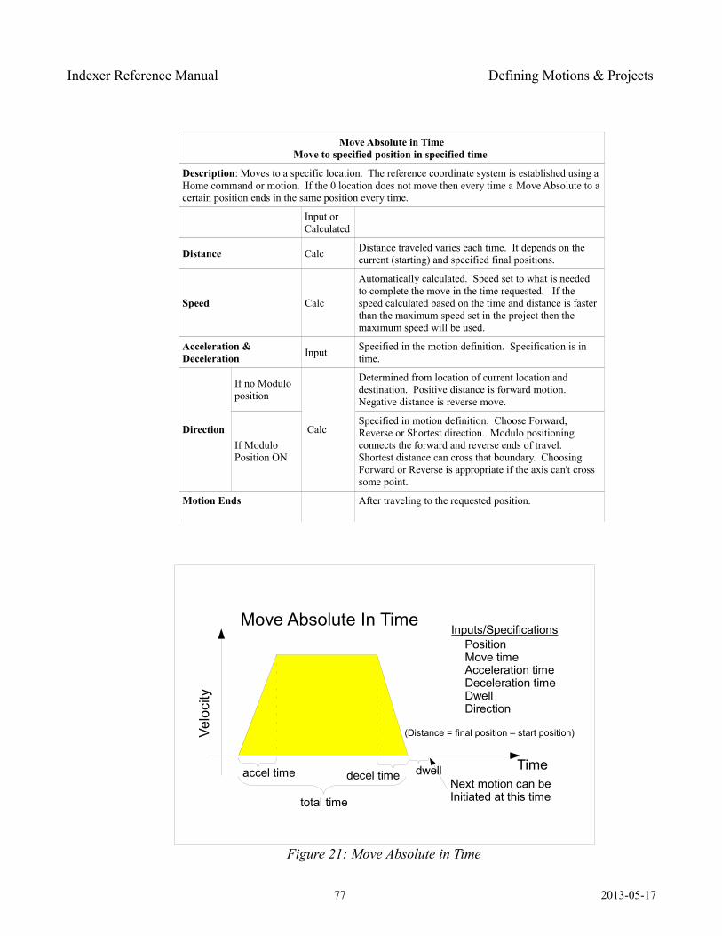
Indexer Reference Manual Defining Motions & Projects
Move Absolute in TimeMove to specified position in specified time
Description: Moves to a specific location. The reference coordinate system is established using a Home command or motion. If the 0 location does not move then every time a Move Absolute to a certain position ends in the same position every time.
Input or Calculated
Distance Calc Distance traveled varies each time. It depends on the current (starting) and specified final positions.
Speed Calc
Automatically calculated. Speed set to what is needed to complete the move in the time requested. If the speed calculated based on the time and distance is faster than the maximum speed set in the project then the maximum speed will be used.
Acceleration & Deceleration Input Specified in the motion definition. Specification is in
time.
Direction
If no Modulo position
Calc
Determined from location of current location and destination. Positive distance is forward motion. Negative distance is reverse move.
If Modulo Position ON
Specified in motion definition. Choose Forward, Reverse or Shortest direction. Modulo positioning connects the forward and reverse ends of travel. Shortest distance can cross that boundary. Choosing Forward or Reverse is appropriate if the axis can't cross some point.
Motion Ends After traveling to the requested position.
77 2013-05-17
Figure 21: Move Absolute in Time
Move Absolute In Time
Time
Velo
city
Inputs/SpecificationsPositionMove timeAcceleration timeDeceleration timeDwellDirection
dwellNext motion can beInitiated at this time
accel time
total time
decel time
(Distance = final position – start position)
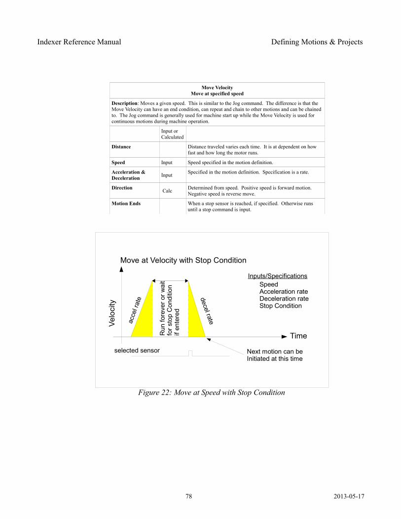
Indexer Reference Manual Defining Motions & Projects
Move VelocityMove at specified speed
Description: Moves a given speed. This is similar to the Jog command. The difference is that the Move Velocity can have an end condition, can repeat and chain to other motions and can be chained to. The Jog command is generally used for machine start up while the Move Velocity is used for continuous motions during machine operation.
Input or Calculated
Distance Distance traveled varies each time. It is at dependent on how fast and how long the motor runs.
Speed Input Speed specified in the motion definition.
Acceleration & Deceleration Input Specified in the motion definition. Specification is a rate.
Direction Calc Determined from speed. Positive speed is forward motion. Negative speed is reverse move.
Motion Ends When a stop sensor is reached, if specified. Otherwise runs until a stop command is input.
78 2013-05-17
Figure 22: Move at Speed with Stop Condition
Move at Velocity with Stop Condition
Time
Velo
city
Inputs/SpecificationsSpeedAcceleration rateDeceleration rateStop Condition
Next motion can beInitiated at this time
acce
l rat
e decel rate
Run
fore
ver o
r wai
tfo
r sto
p C
ondi
tion
if en
tere
d
selected sensor
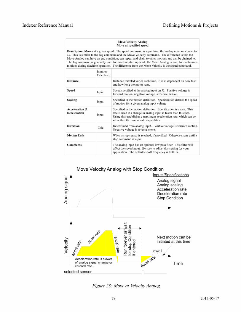
Indexer Reference Manual Defining Motions & Projects
Move Velocity AnalogMove at specified speed
Description: Moves at a given speed. The speed command is input from the analog input on connector J3. This is similar to the Jog command and the Move Velocity command. The difference is that the Move Analog can have an end condition, can repeat and chain to other motions and can be chained to. The Jog command is generally used for machine start up while the Move Analog is used for continuous motions during machine operation. The difference from the Move Velocity is the speed command.
Input or Calculated
Distance Distance traveled varies each time. It is at dependent on how fast and how long the motor runs.
Speed Input Speed specified at the analog input on J3. Positive voltage is forward motion, negative voltage is reverse motion.
Scaling Input Specified in the motion definition. Specification defines the speed of motion for a given analog input voltage
Acceleration & Deceleration Input
Specified in the motion definition. Specification is a rate. This rate is used if a change in analog input is faster than this rate. Using this establishes a maximum acceleration rate, which can be set within the motors safe capabilities.
Direction Calc Determined from analog input. Positive voltage is forward motion. Negative voltage is reverse move.
Motion Ends When a stop sensor is reached, if specified. Otherwise runs until a stop command is input.
Comments The analog input has an optional low pass filter. This filter will effect the speed input. Be sure to adjust this setting for your application. The default cutoff frequency is 100 Hz.
79 2013-05-17
Figure 23: Move at Velocity Analog
Move Velocity Analog with Stop Condition
Time
Velo
city
Inputs/SpecificationsAnalog signalAnalog scalingAcceleration rateDeceleration rateStop Condition
Next motion can beinitiated at this time
acce
l rat
e
decel rate
Run
fore
ver o
r wai
tfo
r sto
p C
ondi
tion
if en
tere
d
selected sensor
Ana
log
sign
al
acce
l rate
accel rate dwell
Acceleration rate is slower of analog signal change orentered rate.
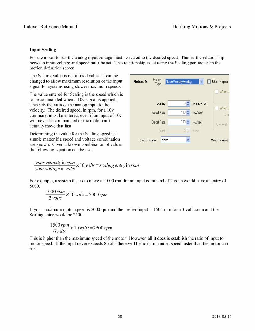
Indexer Reference Manual Defining Motions & Projects
Input Scaling
For the motor to run the analog input voltage must be scaled to the desired speed. That is, the relationship between input voltage and speed must be set. This relationship is set using the Scaling parameter on the motion definition screen.
The Scaling value is not a fixed value. It can be changed to allow maximum resolution of the input signal for systems using slower maximum speeds.
The value entered for Scaling is the speed which is to be commanded when a 10v signal is applied. This sets the ratio of the analog input to the velocity. The desired speed, in rpm, for a 10v command must be entered, even if an input of 10v will never be commanded or the motor can't actually move that fast.
Determining the value for the Scaling speed is a simple matter if a speed and voltage combination are known. Given a known combination of values the following equation can be used.
For example, a system that is to move at 1000 rpm for an input command of 2 volts would have an entry of 5000.
If your maximum motor speed is 2000 rpm and the desired input is 1500 rpm for a 3 volt command the Scaling entry would be 2500.
This is higher than the maximum speed of the motor. However, all it does is establish the ratio of input to motor speed. If the input never exceeds 8 volts there will be no commanded speed faster than the motor can run.
80 2013-05-17
your velocity in rpmyour voltage in volts
×10 volts=scaling entry in rpm
1000 rpm2 volts
×10volts=5000rpm
1500 rpm6volts
×10volts=2500 rpm
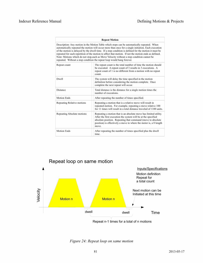
Indexer Reference Manual Defining Motions & Projects
Repeat Motion
Description: Any motion in the Motion Table which stops can be automatically repeated. When automatically repeated the motion will occur more than once for a single initiation. Each execution of the motion is delayed by the dwell time. If a stop condition is defined for the motion it must be repeated for each repetition of the motion to affect that motion. If not the motion ends as defined.Note: Motions which do not stop,such as Move Velocity without a stop condition cannot be repeated. Without a stop condition the repeat loop would hang forever.
Repeat count The repeat count is the total number of time the motion should be executed. A repeat count of 3 results in 3 executions. A repeat count of 1 is no different from a motion with no repeat count.
Dwell The system will delay the time specified in the motion definition before considering the motion complete. Once complete the next repeat will occur.
Distance Total distance is the distance for a single motion times the number of executions.
Motion Ends After repeating the number of times specified.
Repeating Relative motions Repeating a motion that is a relative move will result in repeated motion. For example, repeating a move relative 100 for 11 times will result in a total distance traveled of 1100 units.
Repeating Absolute motions Repeating a motion that is an absolute move has limited utility. After the first execution the system will be at the specified absolute position. Repeating that command (move to absolute position) is effectively a move to where the motor is, a 0 length move.
Motion Ends After repeating the number of times specified plus the dwell time.
81 2013-05-17
Figure 24: Repeat loop on same motion
Repeat loop on same motion
Time
Velo
city
Inputs/SpecificationsMotion definitionRepeat fora total count
dwell
Next motion can beInitiated at this time
Motion n Motion n
dwell
Repeat n-1 times for a total of n motions
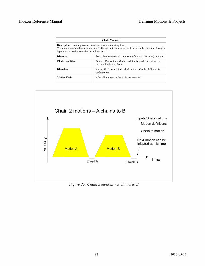
Indexer Reference Manual Defining Motions & Projects
Chain Motions
Description: Chaining connects two or more motions together. Chaining is useful when a sequence of different motions can be run from a single initiation. A sensor input can be used to start the second motion.
Distance Total distance traveled is the sum of the two (or more) motions.
Chain condition Option. Determines which condition is needed to initiate the next motion in the chain.
Direction As specified in each individual motion. Can be different for each motion.
Motion Ends After all motions in the chain are executed.
82 2013-05-17
Figure 25: Chain 2 motions - A chains to B
Chain 2 motions – A chains to B
Time
Velo
city
Inputs/SpecificationsMotion definitions
Chain to motion
Dwell A
Next motion can beInitiated at this time
Motion A Motion B
Dwell B
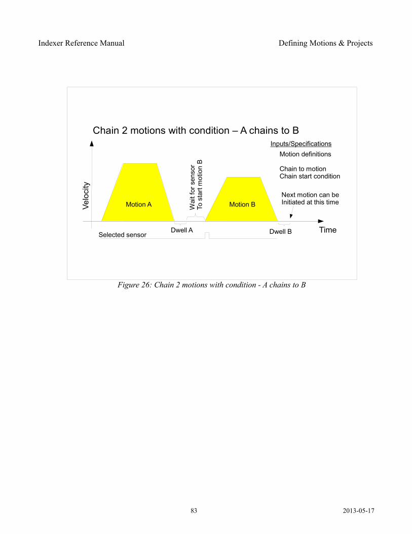
Indexer Reference Manual Defining Motions & Projects
83 2013-05-17
Figure 26: Chain 2 motions with condition - A chains to B
Chain 2 motions with condition – A chains to B
Time
Velo
city
Inputs/SpecificationsMotion definitions
Chain to motionChain start condition
Dwell A
Next motion can beInitiated at this timeMotion A Motion B
Dwell BSelected sensor
Wai
t for
sen
sor
To s
tart
mot
ion
B
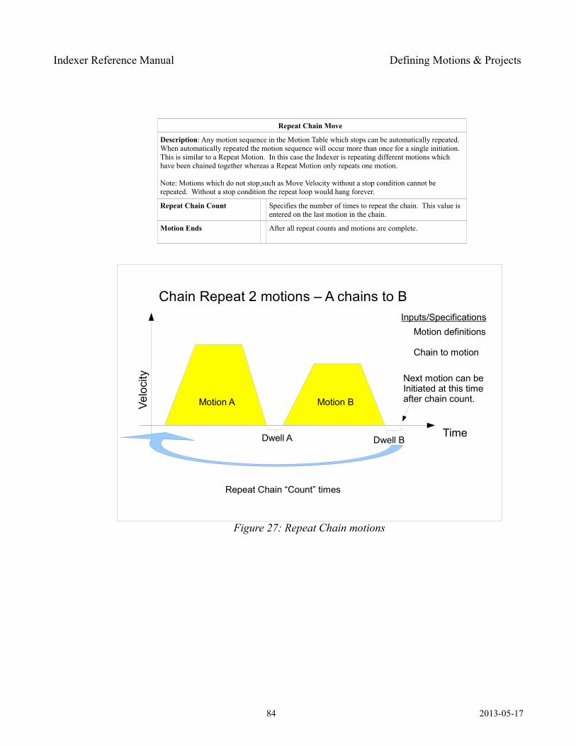
Indexer Reference Manual Defining Motions & Projects
Repeat Chain Move
Description: Any motion sequence in the Motion Table which stops can be automatically repeated. When automatically repeated the motion sequence will occur more than once for a single initiation. This is similar to a Repeat Motion. In this case the Indexer is repeating different motions which have been chained together whereas a Repeat Motion only repeats one motion.
Note: Motions which do not stop,such as Move Velocity without a stop condition cannot be repeated. Without a stop condition the repeat loop would hang forever.
Repeat Chain Count Specifies the number of times to repeat the chain. This value is entered on the last motion in the chain.
Motion Ends After all repeat counts and motions are complete.
84 2013-05-17
Figure 27: Repeat Chain motions
Chain Repeat 2 motions – A chains to B
Time
Velo
city
Inputs/SpecificationsMotion definitions
Chain to motion
Dwell A
Next motion can beInitiated at this timeafter chain count.Motion A Motion B
Dwell B
Repeat Chain “Count” times
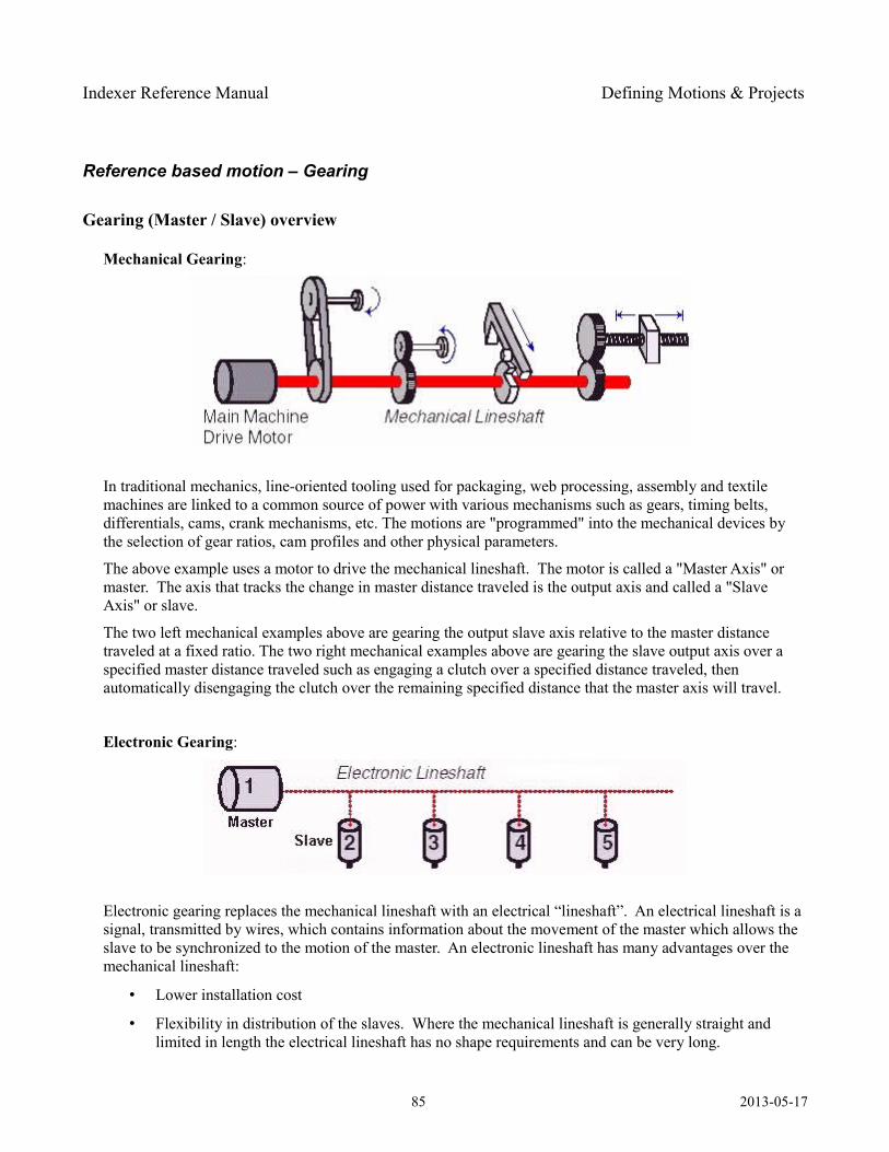
Indexer Reference Manual Defining Motions & Projects
Reference based motion – Gearing
Gearing (Master / Slave) overview
Mechanical Gearing:
In traditional mechanics, line-oriented tooling used for packaging, web processing, assembly and textile machines are linked to a common source of power with various mechanisms such as gears, timing belts, differentials, cams, crank mechanisms, etc. The motions are "programmed" into the mechanical devices by the selection of gear ratios, cam profiles and other physical parameters.
The above example uses a motor to drive the mechanical lineshaft. The motor is called a "Master Axis" or master. The axis that tracks the change in master distance traveled is the output axis and called a "Slave Axis" or slave.
The two left mechanical examples above are gearing the output slave axis relative to the master distance traveled at a fixed ratio. The two right mechanical examples above are gearing the slave output axis over a specified master distance traveled such as engaging a clutch over a specified distance traveled, then automatically disengaging the clutch over the remaining specified distance that the master axis will travel.
Electronic Gearing:
Electronic gearing replaces the mechanical lineshaft with an electrical “lineshaft”. An electrical lineshaft is a signal, transmitted by wires, which contains information about the movement of the master which allows the slave to be synchronized to the motion of the master. An electronic lineshaft has many advantages over the mechanical lineshaft:
• Lower installation cost
• Flexibility in distribution of the slaves. Where the mechanical lineshaft is generally straight and limited in length the electrical lineshaft has no shape requirements and can be very long.
85 2013-05-17

Indexer Reference Manual Defining Motions & Projects
• Multiple levels of slaving is easy. Sub-shafts are possible, with slaves moving relative to another slave's motion rather than the master.
• Greater flexibility in gear ratios
• Software configurable gear ratios make product changes fast
The Indexer supports electronic lineshafts and sub-shafts using a standard A quad B input. The source of the electronic lineshaft can be another Indexer or any motor or encoder with A quad B output attached to the machine. The Indexer has another significant advantage over a mechanical lineshaft – time based or synchronized motion. The Indexer functionality goes beyond just replacing the mechanical lineshaft. It is possible to command motion which are independent of the master, which take place without the master. These are time based motions. The most obvious use is in machine power up positioning. The slave axis can be homed and or positioned at power up without the master running. Less obvious is the ability to run some products in which the slave axis requires synchronization to the master and others which don't. Changing between modes can be as simple as an I/O setting or loading a different recipe.
The Indexer supports two types of geared motion:
• running at a gear ratio until told to stop – Gear In motion
• moving a specific distance at a speed relative to the master then stopping – Gear Relative motion
Details of each type are presented below. Before jumping to the details some helpful general information is presented. When setting up a geared motion:
• The external motion source typically is another motor on the machine, a motor on a machine feeding this one or an encoder connected to the machine. In these cases the source (master) provides an A quad B signal which must be connected at J7 Pacer (Aux) Feedback connector. That connector is only present when the Indexer is ordered with the Pacer Feedback option. That option supports receiving and sending a quadrature signal.
• Gear relative motions follow the “forward” direction of the master. Forward is defined as A leading B at the J7 connector. This can be verified using the MotionSet Monitor screen, turning the master and noting the direction of counting of the Aux position. If forward is wired opposite your needs you must either change the wiring or define the configuration to have the direction Inverted. The configuration can be found on the Setup | Settings tab.
• The slave speed is set as a ratio using two 32-bit numbers. Using two large numbers allows very accurate non-integer ratios. The speed is the ratio of the two numbers. It is not necessary to use the encoder resolutions. For example, if the master is 3000 counts / rev and the slave is 4000 counts / rev and the desired speed is 1 revolution of the master yields 1 revolution of the slave then the ratio is 4000 slave units : 3000 master units. This is the same as 8000 : 6000 or 40000 : 30000. The advantage of the 32-bit numbers is in very minor speed changes. For example, consider a master and
86 2013-05-17
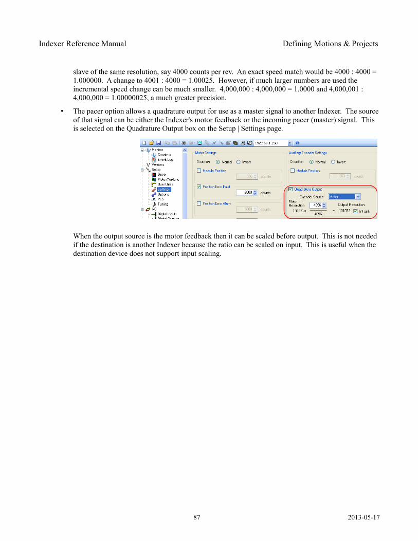
Indexer Reference Manual Defining Motions & Projects
slave of the same resolution, say 4000 counts per rev. An exact speed match would be 4000 : 4000 = 1.000000. A change to 4001 : 4000 = 1.00025. However, if much larger numbers are used the incremental speed change can be much smaller. 4,000,000 : 4,000,000 = 1.0000 and 4,000,001 : 4,000,000 = 1.00000025, a much greater precision.
• The pacer option allows a quadrature output for use as a master signal to another Indexer. The source of that signal can be either the Indexer's motor feedback or the incoming pacer (master) signal. This is selected on the Quadrature Output box on the Setup | Settings page.
When the output source is the motor feedback then it can be scaled before output. This is not needed if the destination is another Indexer because the ratio can be scaled on input. This is useful when the destination device does not support input scaling.
87 2013-05-17
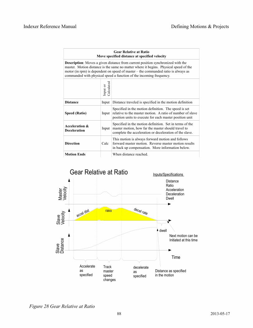
Indexer Reference Manual Defining Motions & Projects
Gear Relative at RatioMove specified distance at specified velocity
Description: Moves a given distance from current position synchronized with the master. Motion distance is the same no matter where it begins. Physical speed of the motor (in rpm) is dependent on speed of master – the commanded ratio is always as commanded with physical speed a function of the incoming frequency.
Distance Input Distance traveled is specified in the motion definition
Speed (Ratio) InputSpecified in the motion definition. The speed is set relative to the master motion. A ratio of number of slave position units to execute for each master position unit
Acceleration & Deceleration Input
Specified in the motion definition. Set in terms of the master motion, how far the master should travel to complete the acceleration or deceleration of the slave.
Direction CalcThis motion is always forward motion and follows forward master motion. Reverse master motion results in back up compensation. More information below.
Motion Ends When distance reached.
88 2013-05-17
Inpu
t or
Cal
cula
ted
Figure 28 Gear Relative at Ratio
Gear Relative at Ratio
Time
accel dist decel rateratio
Inputs/Specifications
DistanceRatioAccelerationDecelerationDwell
dwellNext motion can beInitiated at this time
Mas
ter
Veloc
itySl
ave
Veloc
itySl
ave
Dista
nce
Accelerateasspecified
decelerateasspecified
Trackmaster speedchanges
Distance as specifiedin the motion
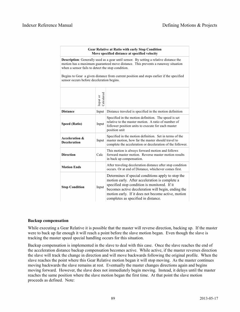
Indexer Reference Manual Defining Motions & Projects
Gear Relative at Ratio with early Stop ConditionMove specified distance at specified velocity
Description: Generally used as a gear until sensor. By setting a relative distance the motion has a maximum guaranteed move distance. This prevents a runaway situation when a sensor fails to detect the stop condition.
Begins to Gear a given distance from current position and stops earlier if the specified sensor occurs before deceleration begins.
Distance Input Distance traveled is specified in the motion definition
Speed (Ratio) Input
Specified in the motion definition. The speed is set relative to the master motion. A ratio of number of follower position units to execute for each master position unit
Acceleration & Deceleration Input
Specified in the motion definition. Set in terms of the master motion, how far the master should travel to complete the acceleration or deceleration of the follower.
Direction CalcThis motion is always forward motion and follows forward master motion. Reverse master motion results in back up compensation.
Motion Ends After traveling deceleration distance after stop condition occurs. Or at end of Distance, whichever comes first.
Stop Condition Input
Determines if special conditions apply to stop the motion early. After acceleration is complete a specified stop condition is monitored. If it becomes active deceleration will begin, ending the motion early. If it does not become active, motion completes as specified in distance.
Backup compensation
While executing a Gear Relative it is possible that the master will reverse direction, backing up. If the master were to back up far enough it will reach a point before the slave motion began. Even though the slave is tracking the master speed special handling occurs for this situation.
Backup compensation is implemented in the slave to deal with this case. Once the slave reaches the end of the acceleration distance backup compensation becomes active. While active, if the master reverses direction the slave will track the change in direction and will move backwards following the original profile. When the slave reaches the point where this Gear Relative motion began it will stop moving. As the master continues moving backwards the slave remains at rest. Eventually the master changes directions again and begins moving forward. However, the slave does not immediately begin moving. Instead, it delays until the master reaches the same position where the slave motion began the first time. At that point the slave motion proceeds as defined. Note:
89 2013-05-17
Inpu
t or
Cal
cula
ted
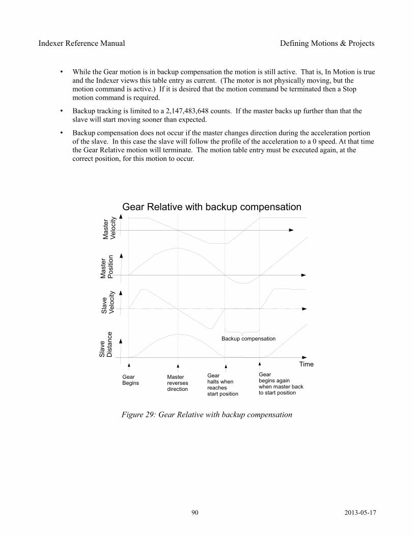
Indexer Reference Manual Defining Motions & Projects
• While the Gear motion is in backup compensation the motion is still active. That is, In Motion is true and the Indexer views this table entry as current. (The motor is not physically moving, but the motion command is active.) If it is desired that the motion command be terminated then a Stop motion command is required.
• Backup tracking is limited to a 2,147,483,648 counts. If the master backs up further than that the slave will start moving sooner than expected.
• Backup compensation does not occur if the master changes direction during the acceleration portion of the slave. In this case the slave will follow the profile of the acceleration to a 0 speed. At that time the Gear Relative motion will terminate. The motion table entry must be executed again, at the correct position, for this motion to occur.
90 2013-05-17
Figure 29: Gear Relative with backup compensation
Gear Relative with backup compensation
Time
Backup compensation
GearBegins
Mas
ter
Velo
city
Mas
ter
Posi
tion
Sla
veD
ista
nce
Sla
veVe
loci
ty
Masterreversesdirection
Gearhalts whenreachesstart position
Gearbegins againwhen master backto start position
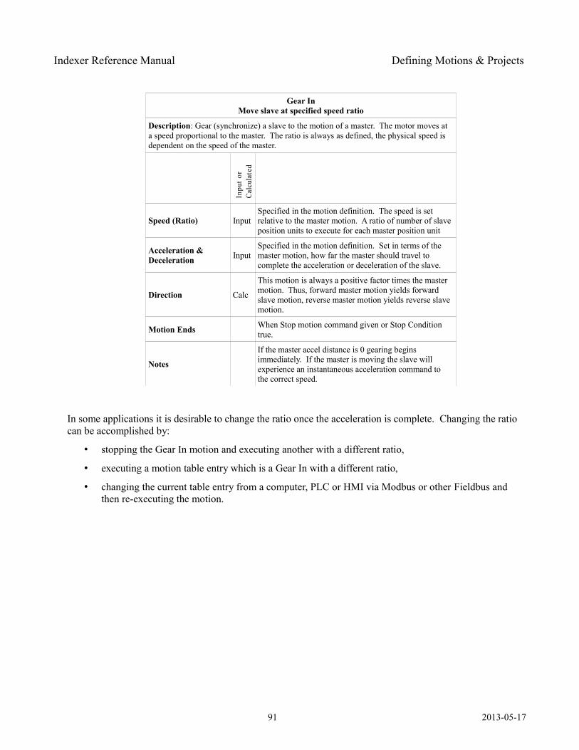
Indexer Reference Manual Defining Motions & Projects
Gear InMove slave at specified speed ratio
Description: Gear (synchronize) a slave to the motion of a master. The motor moves at a speed proportional to the master. The ratio is always as defined, the physical speed is dependent on the speed of the master.
Speed (Ratio) InputSpecified in the motion definition. The speed is set relative to the master motion. A ratio of number of slave position units to execute for each master position unit
Acceleration & Deceleration Input
Specified in the motion definition. Set in terms of the master motion, how far the master should travel to complete the acceleration or deceleration of the slave.
Direction Calc
This motion is always a positive factor times the master motion. Thus, forward master motion yields forward slave motion, reverse master motion yields reverse slave motion.
Motion Ends When Stop motion command given or Stop Condition true.
Notes
If the master accel distance is 0 gearing begins immediately. If the master is moving the slave will experience an instantaneous acceleration command to the correct speed.
In some applications it is desirable to change the ratio once the acceleration is complete. Changing the ratio can be accomplished by:
• stopping the Gear In motion and executing another with a different ratio,
• executing a motion table entry which is a Gear In with a different ratio,
• changing the current table entry from a computer, PLC or HMI via Modbus or other Fieldbus and then re-executing the motion.
91 2013-05-17
Inpu
t or
Cal
cula
ted
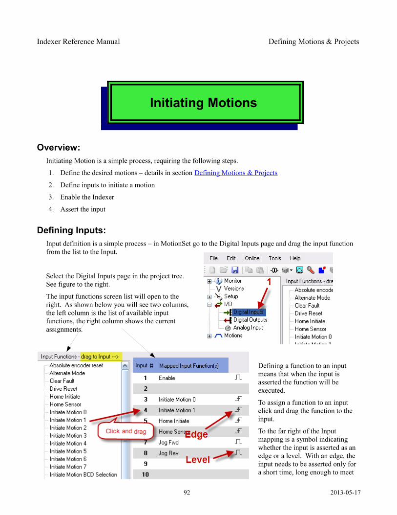
Indexer Reference Manual Defining Motions & Projects
Initiating Motions
Overview: Initiating Motion is a simple process, requiring the following steps.
1. Define the desired motions – details in section Defining Motions & Projects
2. Define inputs to initiate a motion
3. Enable the Indexer
4. Assert the input
Defining Inputs: Input definition is a simple process – in MotionSet go to the Digital Inputs page and drag the input function from the list to the Input.
Select the Digital Inputs page in the project tree. See figure to the right.
The input functions screen list will open to the right. As shown below you will see two columns, the left column is the list of available input functions, the right column shows the current assignments.
Defining a function to an input means that when the input is asserted the function will be executed.
To assign a function to an input click and drag the function to the input.
To the far right of the Input mapping is a symbol indicating whether the input is asserted as an edge or a level. With an edge, the input needs to be asserted only for a short time, long enough to meet
92 2013-05-17

Indexer Reference Manual Initiating Motions
the input debounce time and the input scan time. For level mode the input is asserted only as long as current flows in the input. In the previous example Initiate Motion 1 is an edge mode input. When the input is asserted (current in input) the motion will begin. At that point the input can be unasserted and the motion will continue. In the case of the Jog Fwd input, the Jog will only happen while the input is held asserted.
You can map up to 2 functions on each input. To map a second function, click on the function, drag it to the input number and hover for a moment. A second line will open and you can place the function there.
Changing functions can be done by dragging a function from one input to another or to delete drag it to the trash bin at the bottom of the screen or use a right click.
Asserting Inputs: Inputs are asserted during normal operation based on the electrical connections. In all cases the input is electrically on when current flows in the input. Whether that occurs when a voltage is applied to the input (sourcing inputs) or when the input is grounded (sinking inputs) is determined by the input and connections made. Details for electrically connecting input can be found in section Inputs:
Don't be confused by the symbol in the I/O mapping screen. The symbol is an indication of the logical function of the input, not the electrical state. Thus the edge symbol indicates an edge, where an edge is defined as the transition from unasserted to asserted, that is from no current to current in the input. The level symbol indicates a level, where level is defined as active while current flows.
Inputs can also be asserted using MotionSet and the I/O exerciser.
93 2013-05-17
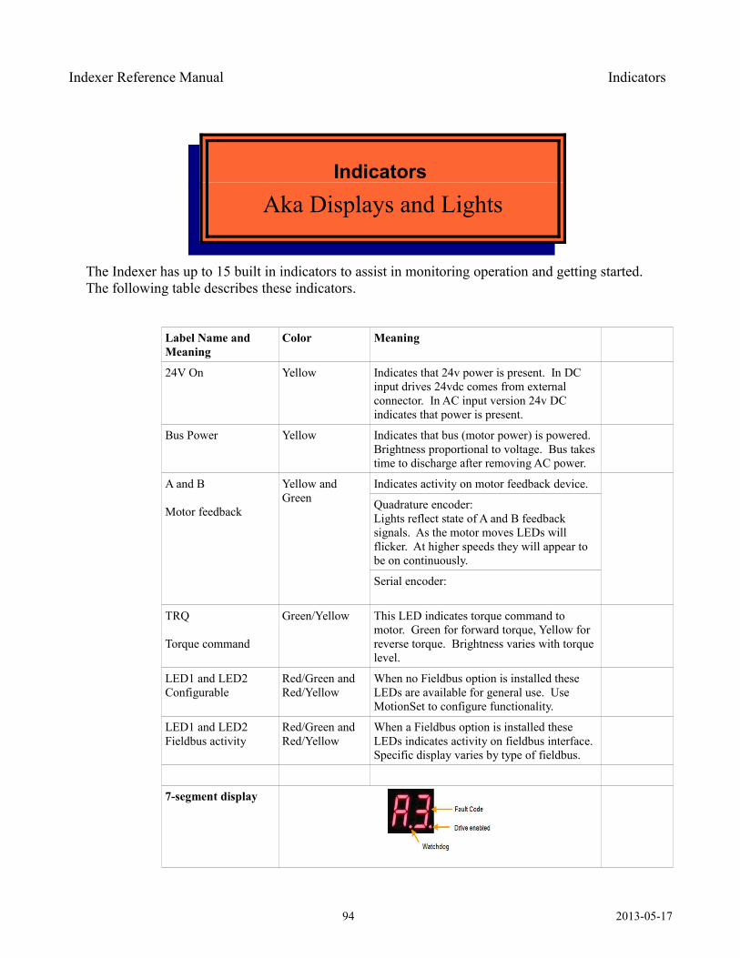
Indexer Reference Manual Indicators
Indicators
Aka Displays and Lights
The Indexer has up to 15 built in indicators to assist in monitoring operation and getting started. The following table describes these indicators.
Label Name and Meaning
Color Meaning
24V On Yellow Indicates that 24v power is present. In DC input drives 24vdc comes from external connector. In AC input version 24v DC indicates that power is present.
Bus Power Yellow Indicates that bus (motor power) is powered. Brightness proportional to voltage. Bus takes time to discharge after removing AC power.
A and B
Motor feedback
Yellow and Green
Indicates activity on motor feedback device.
Quadrature encoder:Lights reflect state of A and B feedback signals. As the motor moves LEDs will flicker. At higher speeds they will appear to be on continuously.
Serial encoder:
TRQ
Torque command
Green/Yellow This LED indicates torque command to motor. Green for forward torque, Yellow for reverse torque. Brightness varies with torque level.
LED1 and LED2Configurable
Red/Green and Red/Yellow
When no Fieldbus option is installed these LEDs are available for general use. Use MotionSet to configure functionality.
LED1 and LED2Fieldbus activity
Red/Green and Red/Yellow
When a Fieldbus option is installed these LEDs indicates activity on fieldbus interface. Specific display varies by type of fieldbus.
7-segment display
94 2013-05-17
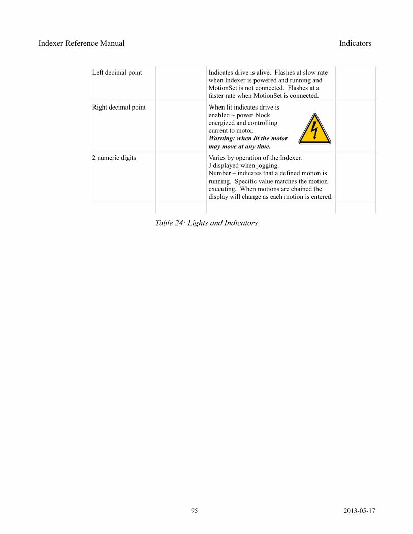
Indexer Reference Manual Indicators
Left decimal point Indicates drive is alive. Flashes at slow rate when Indexer is powered and running and MotionSet is not connected. Flashes at a faster rate when MotionSet is connected.
Right decimal point When lit indicates drive is enabled ~ power block energized and controlling current to motor.Warning: when lit the motor may move at any time.
2 numeric digits Varies by operation of the Indexer. J displayed when jogging.Number – indicates that a defined motion is running. Specific value matches the motion executing. When motions are chained the display will change as each motion is entered.
Table 24: Lights and Indicators
95 2013-05-17
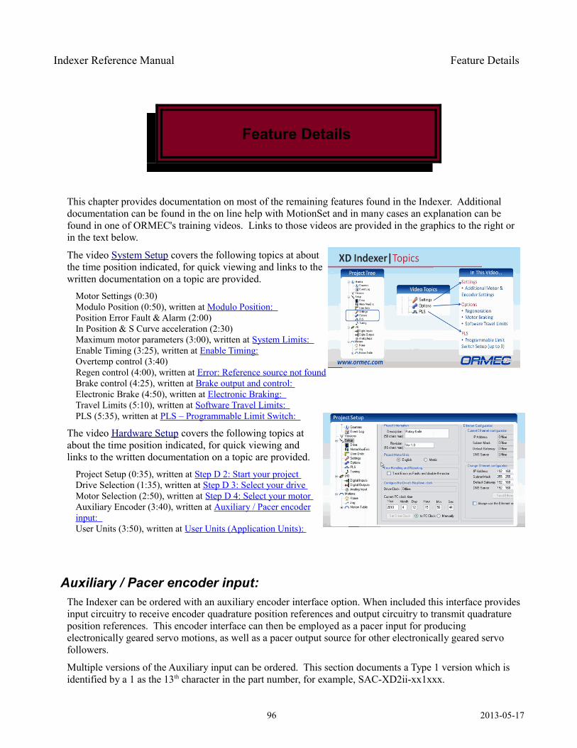
Indexer Reference Manual Feature Details
Feature Details
This chapter provides documentation on most of the remaining features found in the Indexer. Additional documentation can be found in the on line help with MotionSet and in many cases an explanation can be found in one of ORMEC's training videos. Links to those videos are provided in the graphics to the right or in the text below.
The video System Setup covers the following topics at about the time position indicated, for quick viewing and links to the written documentation on a topic are provided.
Motor Settings (0:30)Modulo Position (0:50), written at Modulo Position: Position Error Fault & Alarm (2:00)In Position & S Curve acceleration (2:30)Maximum motor parameters (3:00), written at System Limits: Enable Timing (3:25), written at Enable Timing:Overtemp control (3:40)Regen control (4:00), written at Error: Reference source not foundBrake control (4:25), written at Brake output and control: Electronic Brake (4:50), written at Electronic Braking: Travel Limits (5:10), written at Software Travel Limits: PLS (5:35), written at PLS – Programmable Limit Switch:
The video Hardware Setup covers the following topics at about the time position indicated, for quick viewing and links to the written documentation on a topic are provided.
Project Setup (0:35), written at Step D 2: Start your project Drive Selection (1:35), written at Step D 3: Select your drive Motor Selection (2:50), written at Step D 4: Select your motor Auxiliary Encoder (3:40), written at Auxiliary / Pacer encoderinput: User Units (3:50), written at User Units (Application Units):
Auxiliary / Pacer encoder input: The Indexer can be ordered with an auxiliary encoder interface option. When included this interface provides input circuitry to receive encoder quadrature position references and output circuitry to transmit quadrature position references. This encoder interface can then be employed as a pacer input for producing electronically geared servo motions, as well as a pacer output source for other electronically geared servo followers.
Multiple versions of the Auxiliary input can be ordered. This section documents a Type 1 version which is identified by a 1 as the 13th character in the part number, for example, SAC-XD2ii-xx1xxx.
96 2013-05-17
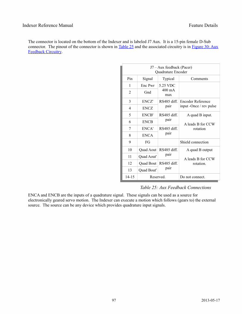
Indexer Reference Manual Feature Details
The connector is located on the bottom of the Indexer and is labeled J7 Aux. It is a 15-pin female D-Sub connector. The pinout of the connector is shown in Table 25 and the associated circuitry is in Figure 30: AuxFeedback Circuitry.
J7 – Aux feedback (Pacer)Quadrature Encoder
Pin Signal Typical Comments
1 Enc Pwr 5.25 VDC400 mA
max2 Gnd
3 ENCZ' RS485 diff. pair
Encoder Reference input -Once / rev pulse4 ENCZ
5 ENCB' RS485 diff. pair
A quad B input.
A leads B for CCW rotation
6 ENCB
7 ENCA' RS485 diff. pair8 ENCA
9 FG Shield connection
10 Quad Aout RS485 diff. pair
A quad B output
A leads B for CCW rotation.
11 Quad Aout'
12 Quad Bout RS485 diff. pair13 Quad Bout'
14-15 Reserved. Do not connect.
Table 25: Aux Feedback Connections ENCA and ENCB are the inputs of a quadrature signal. These signals can be used as a source for electronically geared servo motion. The Indexer can execute a motion which follows (gears to) the external source. The source can be any device which provides quadrature input signals.
97 2013-05-17
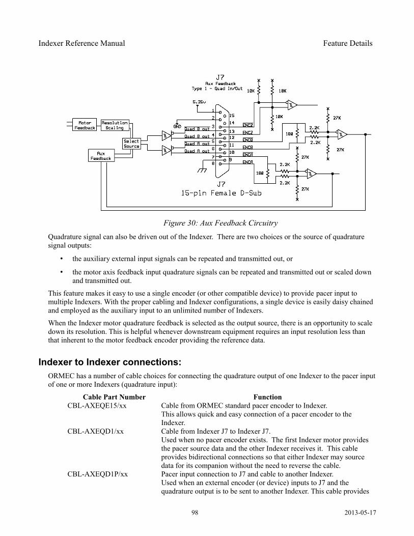
Indexer Reference Manual Feature Details
Quadrature signal can also be driven out of the Indexer. There are two choices or the source of quadrature signal outputs:
• the auxiliary external input signals can be repeated and transmitted out, or
• the motor axis feedback input quadrature signals can be repeated and transmitted out or scaled down and transmitted out.
This feature makes it easy to use a single encoder (or other compatible device) to provide pacer input to multiple Indexers. With the proper cabling and Indexer configurations, a single device is easily daisy chained and employed as the auxiliary input to an unlimited number of Indexers.
When the Indexer motor quadrature feedback is selected as the output source, there is an opportunity to scale down its resolution. This is helpful whenever downstream equipment requires an input resolution less than that inherent to the motor feedback encoder providing the reference data.
Indexer to Indexer connections: ORMEC has a number of cable choices for connecting the quadrature output of one Indexer to the pacer input of one or more Indexers (quadrature input):
Cable Part Number Function CBL-AXEQE15/xx Cable from ORMEC standard pacer encoder to Indexer.
This allows quick and easy connection of a pacer encoder to the Indexer.
CBL-AXEQD1/xx Cable from Indexer J7 to Indexer J7. Used when no pacer encoder exists. The first Indexer motor provides the pacer source data and the other Indexer receives it. This cable provides bidirectional connections so that either Indexer may source data for its companion without the need to reverse the cable.
CBL-AXEQD1P/xx Pacer input connection to J7 and cable to another Indexer.Used when an external encoder (or device) inputs to J7 and the quadrature output is to be sent to another Indexer. This cable provides
98 2013-05-17
Figure 30: Aux Feedback Circuitry
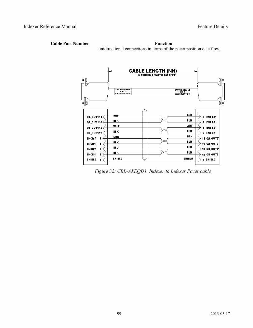
Indexer Reference Manual Feature Details
Cable Part Number Function unidirectional connections in terms of the pacer position data flow.
99 2013-05-17
Figure 31: CBL-AXEQE15 Pacer Encoder to Indexer
Figure 32: CBL-AXEQD1 Indexer to Indexer Pacer cable
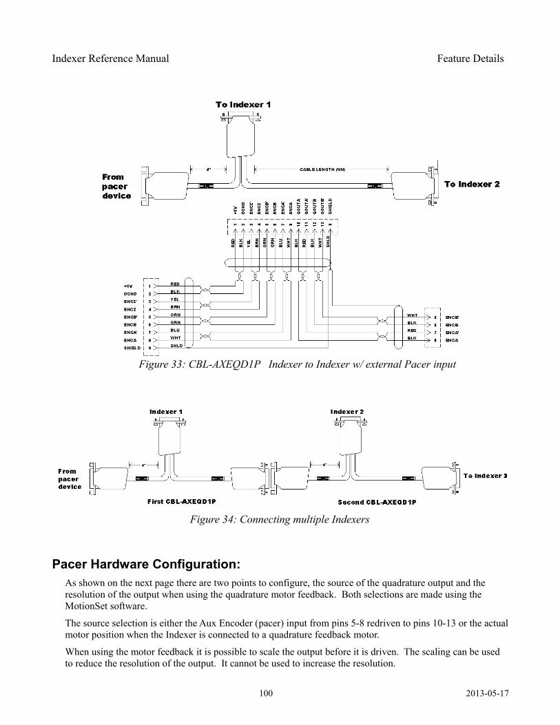
Indexer Reference Manual Feature Details
Pacer Hardware Configuration: As shown on the next page there are two points to configure, the source of the quadrature output and the resolution of the output when using the quadrature motor feedback. Both selections are made using the MotionSet software.
The source selection is either the Aux Encoder (pacer) input from pins 5-8 redriven to pins 10-13 or the actual motor position when the Indexer is connected to a quadrature feedback motor.
When using the motor feedback it is possible to scale the output before it is driven. The scaling can be used to reduce the resolution of the output. It cannot be used to increase the resolution.
100 2013-05-17
Figure 33: CBL-AXEQD1P Indexer to Indexer w/ external Pacer input
Figure 34: Connecting multiple Indexers
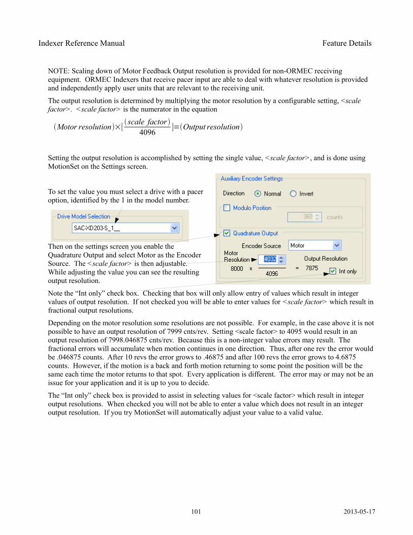
Indexer Reference Manual Feature Details
NOTE: Scaling down of Motor Feedback Output resolution is provided for non-ORMEC receiving equipment. ORMEC Indexers that receive pacer input are able to deal with whatever resolution is provided and independently apply user units that are relevant to the receiving unit.
The output resolution is determined by multiplying the motor resolution by a configurable setting, <scale factor>. <scale factor> is the numerator in the equation
Motor resolution×[ scale factor
4096]=Output resolution
Setting the output resolution is accomplished by setting the single value, <scale factor>, and is done using MotionSet on the Settings screen.
To set the value you must select a drive with a pacer option, identified by the 1 in the model number.
Then on the settings screen you enable the Quadrature Output and select Motor as the Encoder Source. The <scale factor> is then adjustable. While adjusting the value you can see the resulting output resolution.
Note the “Int only” check box. Checking that box will only allow entry of values which result in integer values of output resolution. If not checked you will be able to enter values for <scale factor> which result in fractional output resolutions.
Depending on the motor resolution some resolutions are not possible. For example, in the case above it is not possible to have an output resolution of 7999 cnts/rev. Setting <scale factor> to 4095 would result in an output resolution of 7998.046875 cnts/rev. Because this is a non-integer value errors may result. The fractional errors will accumulate when motion continues in one direction. Thus, after one rev the error would be .046875 counts. After 10 revs the error grows to .46875 and after 100 revs the error grows to 4.6875 counts. However, if the motion is a back and forth motion returning to some point the position will be the same each time the motor returns to that spot. Every application is different. The error may or may not be an issue for your application and it is up to you to decide.
The “Int only” check box is provided to assist in selecting values for <scale factor> which result in integer output resolutions. When checked you will not be able to enter a value which does not result in an integer output resolution. If you try MotionSet will automatically adjust your value to a valid value.
101 2013-05-17
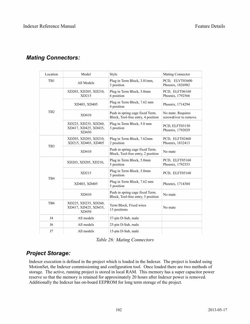
Indexer Reference Manual Feature Details
Mating Connectors:
Location Model Style Mating Connector
TB1 All Models Plug in Term Block, 3.81mm,3 position
PCD, ELVT03600Phoenix, 1826982
TB2
XD203, XD205, XD210, XD215
Plug in Term Block, 5.0mm6 position
PCD, ELFT06160Phoenix, 1792566
XD403, XD405 Plug in Term Block, 7.62 mm4 position Phoenix, 1714294
XD410 Push in spring cage fixed Term. Block, Tool-free entry, 4 position
No mate. Requires screwdriver to remove.
XD225, XD235, XD260, XD417, XD425, XD435,
XD450
Plug in Term Block, 5.0 mm3 position PCD, ELFT03150
Phoenix, 1792029
TB3
XD203, XD205, XD210, XD215, XD403, XD405
Plug in Term Block, 7.62mm2 position
PCD, ELFT02460Phoenix, 1832413
XD410 Push in spring cage fixed Term. Block, Tool-free entry, 2 position No mate
TB4
XD203, XD205, XD210, Plug in Term Block, 5.0mm5 position
PCD, ELFT05160Phoenix, 1792553
XD215 Plug in Term Block, 5.0mm5 position PCD, ELFT05160
XD403, XD405 Plug in Term Block, 7.62 mm5 position Phoenix, 1714304
XD410 Push in spring cage fixed Term. Block, Tool-free entry, 5 position No mate
TB6 XD225, XD235, XD260, XD417, XD425, XD435,
XD450
Term Block, Fixed wires13 positions No mate
J4 All models 37-pin D-Sub, male
J6 All models 25-pin D-Sub, male
J7 All models 15-pin D-Sub, male
Table 26: Mating Connectors
Project Storage: Indexer execution is defined in the project which is loaded in the Indexer. The project is loaded using MotionSet, the Indexer commissioning and configuration tool. Once loaded there are two methods of storage. The active, running project is stored in local RAM. This memory has a super capacitor power reserve so that the memory is retained for approximately 20 hours after Indexer power is removed. Additionally the Indexer has on-board EEPROM for long term storage of the project.
102 2013-05-17
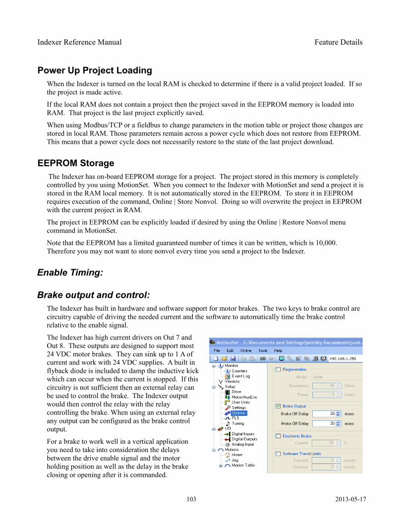
Indexer Reference Manual Feature Details
Power Up Project LoadingWhen the Indexer is turned on the local RAM is checked to determine if there is a valid project loaded. If so the project is made active.
If the local RAM does not contain a project then the project saved in the EEPROM memory is loaded into RAM. That project is the last project explicitly saved.
When using Modbus/TCP or a fieldbus to change parameters in the motion table or project those changes are stored in local RAM. Those parameters remain across a power cycle which does not restore from EEPROM. This means that a power cycle does not necessarily restore to the state of the last project download.
EEPROM Storage The Indexer has on-board EEPROM storage for a project. The project stored in this memory is completely controlled by you using MotionSet. When you connect to the Indexer with MotionSet and send a project it is stored in the RAM local memory. It is not automatically stored in the EEPROM. To store it in EEPROM requires execution of the command, Online | Store Nonvol. Doing so will overwrite the project in EEPROM with the current project in RAM.
The project in EEPROM can be explicitly loaded if desired by using the Online | Restore Nonvol menu command in MotionSet.
Note that the EEPROM has a limited guaranteed number of times it can be written, which is 10,000. Therefore you may not want to store nonvol every time you send a project to the Indexer.
Enable Timing:
Brake output and control: The Indexer has built in hardware and software support for motor brakes. The two keys to brake control are circuitry capable of driving the needed current and the software to automatically time the brake control relative to the enable signal.
The Indexer has high current drivers on Out 7 and Out 8. These outputs are designed to support most 24 VDC motor brakes. They can sink up to 1 A of current and work with 24 VDC supplies. A built in flyback diode is included to damp the inductive kick which can occur when the current is stopped. If this circuitry is not sufficient then an external relay can be used to control the brake. The Indexer output would then control the relay with the relay controlling the brake. When using an external relay any output can be configured as the brake control output.
For a brake to work well in a vertical application you need to take into consideration the delays between the drive enable signal and the motor holding position as well as the delay in the brake closing or opening after it is commanded.
103 2013-05-17
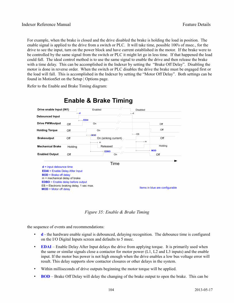
Indexer Reference Manual Feature Details
For example, when the brake is closed and the drive disabled the brake is holding the load in position. The enable signal is applied to the drive from a switch or PLC. It will take time, possible 100's of msec., for the drive to see the input, turn on the power block and have current established in the motor. If the brake were to be controlled by the same signal from the switch or PLC it might let go in less time. If that happened the load could fall. The ideal control method is to use the same signal to enable the drive and then release the brake with a time delay. This can be accomplished in the Indexer by setting the “Brake Off Delay”. Disabling the motor is done in reverse order. When the switch or PLC disables the drive the brake must be engaged first or the load will fall. This is accomplished in the Indexer by setting the “Motor Off Delay”. Both settings can be found in MotionSet on the Setup | Options page.
Refer to the Enable and Brake Timing diagram:
the sequence of events and recommendations:
• d - the hardware enable signal is debounced, delaying recognition. The debounce time is configured on the I/O Digital Inputs screen and defaults to 5 msec.
• EDAI – Enable Delay After Input delays the drive from applying torque. It is primarily used when the same or similar signals close a contactor for motor power (L1, L2 and L3 inputs) and the enable input. If the motor bus power is not high enough when the drive enables a low bus voltage error will result. This delay supports slow contactor closures or other delays in the system.
• Within milliseconds of drive outputs beginning the motor torque will be applied.
• BOD – Brake Off Delay will delay the changing of the brake output to open the brake. This can be
104 2013-05-17
Figure 35: Enable & Brake Timing
Enable & Brake Timing
Time
Drive enable Input (IN1)
Drive PWMoutput
Brakeoutput
Mechanical Brake
OnOff
Off On (sinking current)
Holding Released
Enabled Disabled
Holding
Off
Off
Debounced Input
Holding Torque OnOff
EDAI
d
BOD
Enabled OutputEDBO
d
EB
m
MOD
d = input debounce timeEDAI = Enable Delay After InputBOD = Brake off delay
m
m = mechanical delay of brakeEDBO = Enable delay before outputEB = Electronic braking delay, 1 sec max.MOD = Motor off delay
Off On Off
Off
Items in blue are configurable
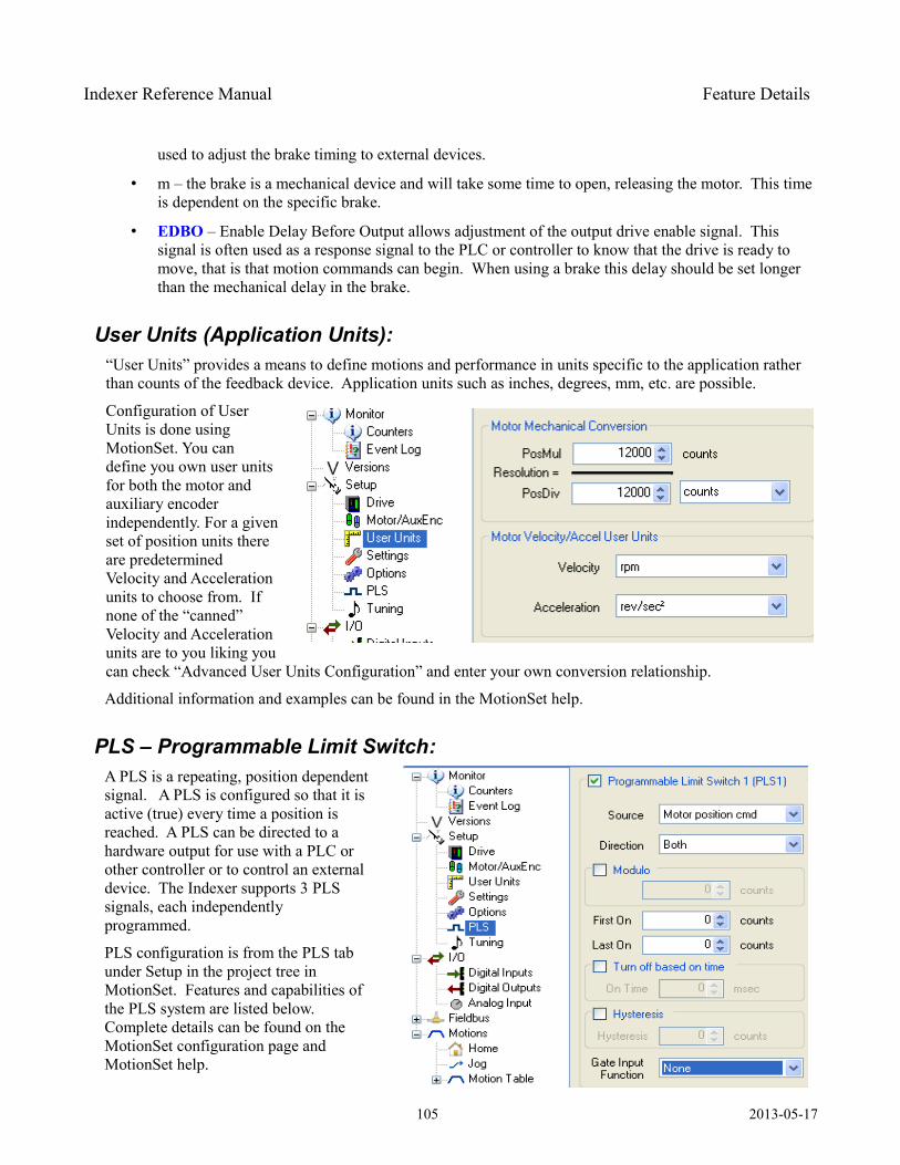
Indexer Reference Manual Feature Details
used to adjust the brake timing to external devices.
• m – the brake is a mechanical device and will take some time to open, releasing the motor. This time is dependent on the specific brake.
• EDBO – Enable Delay Before Output allows adjustment of the output drive enable signal. This signal is often used as a response signal to the PLC or controller to know that the drive is ready to move, that is that motion commands can begin. When using a brake this delay should be set longer than the mechanical delay in the brake.
User Units (Application Units): “User Units” provides a means to define motions and performance in units specific to the application rather than counts of the feedback device. Application units such as inches, degrees, mm, etc. are possible.
Configuration of User Units is done using MotionSet. You can define you own user units for both the motor and auxiliary encoder independently. For a given set of position units there are predetermined Velocity and Acceleration units to choose from. If none of the “canned” Velocity and Acceleration units are to you liking you can check “Advanced User Units Configuration” and enter your own conversion relationship.
Additional information and examples can be found in the MotionSet help.
PLS – Programmable Limit Switch: A PLS is a repeating, position dependent signal. A PLS is configured so that it is active (true) every time a position is reached. A PLS can be directed to a hardware output for use with a PLC or other controller or to control an external device. The Indexer supports 3 PLS signals, each independently programmed.
PLS configuration is from the PLS tab under Setup in the project tree in MotionSet. Features and capabilities of the PLS system are listed below. Complete details can be found on the MotionSet configuration page and MotionSet help.
105 2013-05-17
Indexer Reference Manual Feature Details
PLS features and capabilities:
• Choice of position source – Actual motor position, Commanded motor position and auxiliary encoder actual position.
Actual motor position is the position of the motor connected to the J6 feedback connector.
Commanded motor position is the position commanded by any motions.
Aux encoder actual position is the actual position of the feedback device connected to J7.
• Operation with or without modulo positioning. With modulo positioning turned on the position repeats at a regular cycle. It is usually used in rotary systems so that a PLS will repeat at the same position every revolution.
• The turn on position (First On position) is a numeric value and can trigger a PLS output. In forward motion this defines the turn on point, in reverse motion it defines the turn off point.
• The turn off position (LastOnPosition) is a numeric value. In forward motion defines the point to turn off the PLS and in reverse motion it defines the turn on point.
• PLS turn off can be a position or time based.
• Hysteresis is supported.
• The PLS can be gated for enable. The gate signal enables a PLS when the turn on position is reached when true. When the gate signal is false no PLS output will occur even if the turn on position is reached.
In this example Modulo positioning is not used with the PLS. Therefore, in a system where the motor is continuously moving in the same direction the PLS will be true only once. It then remains off unless the motor moves back to near the origin.
This example also shows the power of combined outputs. OUT1 has PLS1 mapped to it. OUT1 therefore follows the state of PLS1. However, OUT2 has a logical combination of PLS1 and PLS2, they are ORed together. When either PLS1 OR PLS2 is active OUT2 will be on.
106 2013-05-17
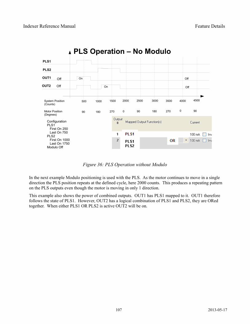
Indexer Reference Manual Feature Details
In the next example Modulo positioning is used with the PLS. As the motor continues to move in a single direction the PLS position repeats at the defined cycle, here 2000 counts. This produces a repeating pattern on the PLS outputs even though the motor is moving in only 1 direction.
This example also shows the power of combined outputs. OUT1 has PLS1 mapped to it. OUT1 therefore follows the state of PLS1. However, OUT2 has a logical combination of PLS1 and PLS2, they are ORed together. When either PLS1 OR PLS2 is active OUT2 will be on.
107 2013-05-17
Figure 36: PLS Operation without Modulo
PLS Operation – No ModuloPLS1
OUT1 OnOff
500
Off
Off
PLS2
OUT2 OnOff
ConfigurationPLS1 First On 250 Last On 750PLS2 First On 1000 Last On 1750Modulo Off
System Position(Counts)
1000 1500 2000 2500 3000 3500 4000 4500
Motor Position(Degrees)
90 180 270 0 90 180 270 0 90
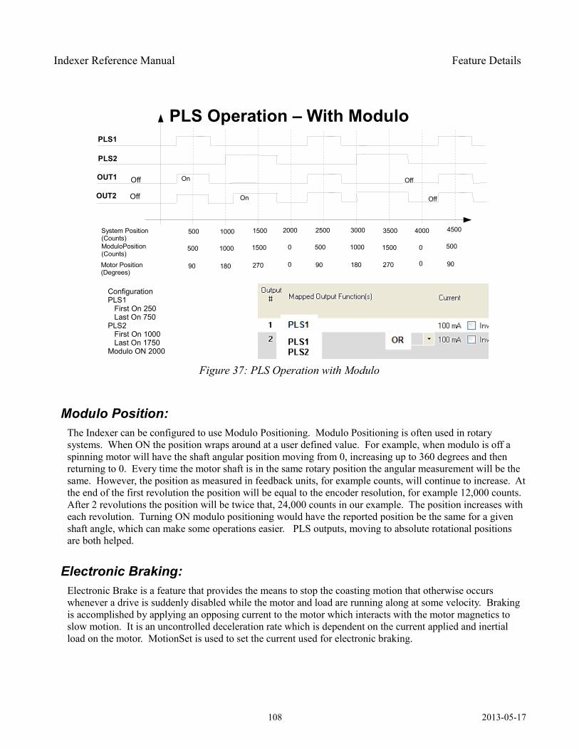
Indexer Reference Manual Feature Details
Modulo Position: The Indexer can be configured to use Modulo Positioning. Modulo Positioning is often used in rotary systems. When ON the position wraps around at a user defined value. For example, when modulo is off a spinning motor will have the shaft angular position moving from 0, increasing up to 360 degrees and then returning to 0. Every time the motor shaft is in the same rotary position the angular measurement will be the same. However, the position as measured in feedback units, for example counts, will continue to increase. At the end of the first revolution the position will be equal to the encoder resolution, for example 12,000 counts. After 2 revolutions the position will be twice that, 24,000 counts in our example. The position increases with each revolution. Turning ON modulo positioning would have the reported position be the same for a given shaft angle, which can make some operations easier. PLS outputs, moving to absolute rotational positions are both helped.
Electronic Braking: Electronic Brake is a feature that provides the means to stop the coasting motion that otherwise occurs whenever a drive is suddenly disabled while the motor and load are running along at some velocity. Braking is accomplished by applying an opposing current to the motor which interacts with the motor magnetics to slow motion. It is an uncontrolled deceleration rate which is dependent on the current applied and inertial load on the motor. MotionSet is used to set the current used for electronic braking.
108 2013-05-17
Figure 37: PLS Operation with Modulo
PLS Operation – With ModuloPLS1
OUT1 OnOff
500
Off
Off
PLS2
OUT2 OnOff
ConfigurationPLS1 First On 250 Last On 750PLS2 First On 1000 Last On 1750Modulo ON 2000
System Position(Counts)
1000 1500 2000 2500 3000 3500 4000 4500
Motor Position(Degrees)
90 180 270 0 90 180 270 0 90
ModuloPosition(Counts)
500 1000 1500 0 500 1000 1500 0 500
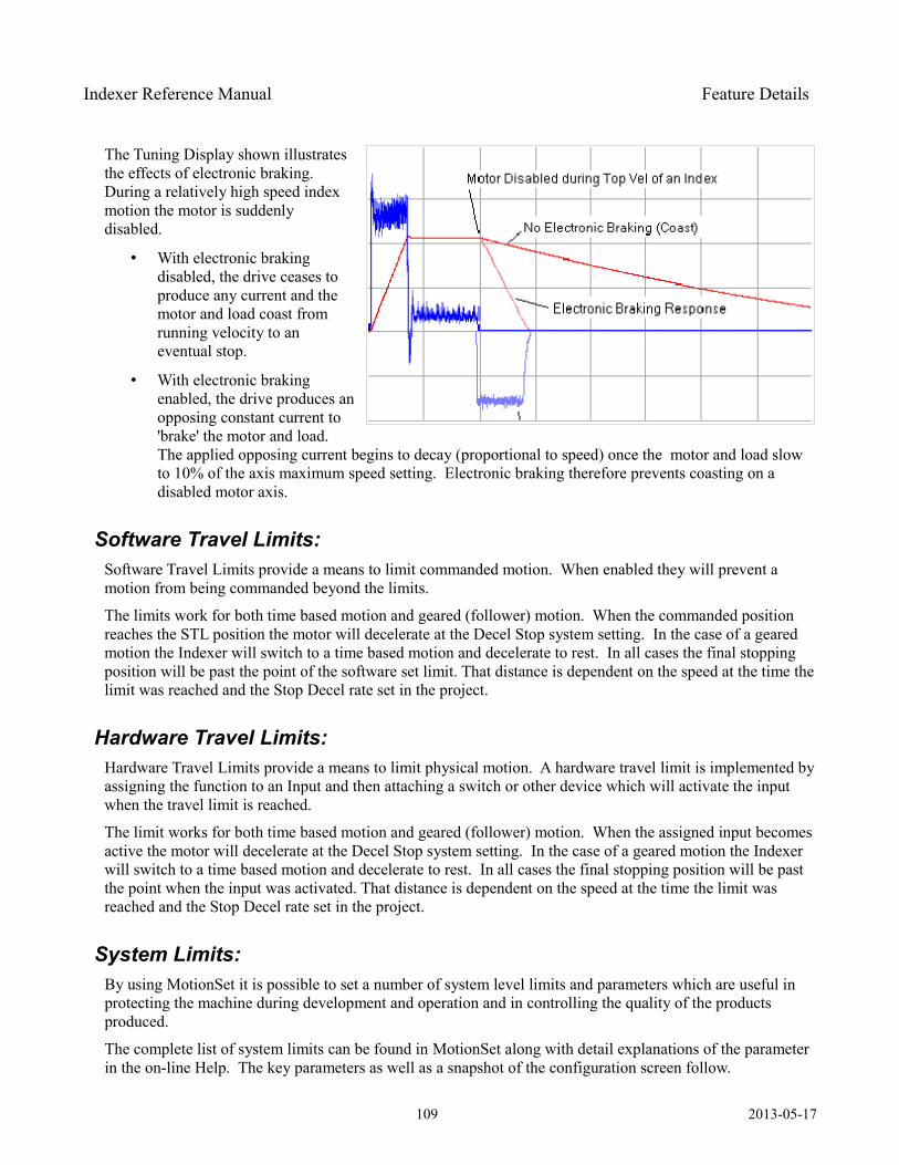
Indexer Reference Manual Feature Details
The Tuning Display shown illustrates the effects of electronic braking. During a relatively high speed index motion the motor is suddenly disabled.
• With electronic braking disabled, the drive ceases to produce any current and the motor and load coast from running velocity to an eventual stop.
• With electronic braking enabled, the drive produces an opposing constant current to 'brake' the motor and load. The applied opposing current begins to decay (proportional to speed) once the motor and load slow to 10% of the axis maximum speed setting. Electronic braking therefore prevents coasting on a disabled motor axis.
Software Travel Limits: Software Travel Limits provide a means to limit commanded motion. When enabled they will prevent a motion from being commanded beyond the limits.
The limits work for both time based motion and geared (follower) motion. When the commanded position reaches the STL position the motor will decelerate at the Decel Stop system setting. In the case of a geared motion the Indexer will switch to a time based motion and decelerate to rest. In all cases the final stopping position will be past the point of the software set limit. That distance is dependent on the speed at the time the limit was reached and the Stop Decel rate set in the project.
Hardware Travel Limits: Hardware Travel Limits provide a means to limit physical motion. A hardware travel limit is implemented by assigning the function to an Input and then attaching a switch or other device which will activate the input when the travel limit is reached.
The limit works for both time based motion and geared (follower) motion. When the assigned input becomes active the motor will decelerate at the Decel Stop system setting. In the case of a geared motion the Indexer will switch to a time based motion and decelerate to rest. In all cases the final stopping position will be past the point when the input was activated. That distance is dependent on the speed at the time the limit was reached and the Stop Decel rate set in the project.
System Limits: By using MotionSet it is possible to set a number of system level limits and parameters which are useful in protecting the machine during development and operation and in controlling the quality of the products produced.
The complete list of system limits can be found in MotionSet along with detail explanations of the parameter in the on-line Help. The key parameters as well as a snapshot of the configuration screen follow.
109 2013-05-17
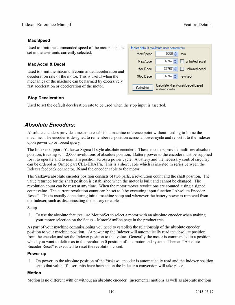
Indexer Reference Manual Feature Details
Max Speed Used to limit the commanded speed of the motor. This is set in the user units currently selected.
Max Accel & DecelUsed to limit the maximum commanded acceleration and deceleration rate of the motor. This is useful when the mechanics of the machine can be harmed by excessively fast acceleration or deceleration of the motor.
Stop Deceleration Used to set the default deceleration rate to be used when the stop input is asserted.
Absolute Encoders: Absolute encoders provide a means to establish a machine reference point without needing to home the machine. The encoder is designed to remember its position across a power cycle and report it to the Indexer upon power up or forced query.
The Indexer supports Yaskawa Sigma II style absolute encoders. These encoders provide multi-rev absolute position, tracking +/- 12,000 revolutions of absolute position. Battery power to the encoder must be supplied for it to operate and to maintain position across a power cycle. A battery and the necessary control circuitry can be ordered as Ormec part CBL-HBAT/n. This is a short cable which is inserted in series between the Indexer feedback connector, J6 and the encoder cable to the motor.
The Yaskawa absolute encoder position consists of two parts, a revolution count and the shaft position. The value returned for the shaft position is established when the motor is built and cannot be changed. The revolution count can be reset at any time. When the motor moves revolutions are counted, using a signed count value. The current revolution count can be set to 0 by executing input function “Absolute Encoder Reset”. This is usually done during initial machine setup and whenever the battery power is removed from the Indexer, such as disconnecting the battery or cables.
Setup
1. To use the absolute features, use MotionSet to select a motor with an absolute encoder when making your motor selection on the Setup – Motor/AuxEnc page in the product tree.
As part of your machine commissioning you need to establish the relationship of the absolute encoder position to your machine position. At power up the Indexer will automatically read the absolute position from the encoder and set the Indexer position to that value. Generally the motor is commanded to a position which you want to define as in the revolution 0 position of the motor and system. Then an “Absolute Encoder Reset” is executed to reset the revolution count.
Power up1. On power up the absolute position of the Yaskawa encoder is automatically read and the Indexer position
set to that value. If user units have been set on the Indexer a conversion will take place.
MotionMotion is no different with or without an absolute encoder. Incremental motions as well as absolute motions
110 2013-05-17
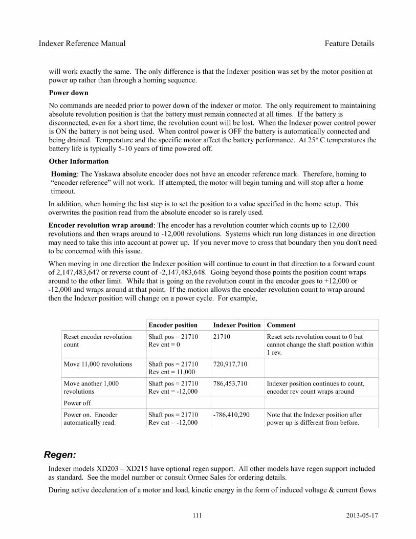
Indexer Reference Manual Feature Details
will work exactly the same. The only difference is that the Indexer position was set by the motor position at power up rather than through a homing sequence.
Power down
No commands are needed prior to power down of the indexer or motor. The only requirement to maintaining absolute revolution position is that the battery must remain connected at all times. If the battery is disconnected, even for a short time, the revolution count will be lost. When the Indexer power control power is ON the battery is not being used. When control power is OFF the battery is automatically connected and being drained. Temperature and the specific motor affect the battery performance. At 25o C temperatures the battery life is typically 5-10 years of time powered off.
Other Information
Homing: The Yaskawa absolute encoder does not have an encoder reference mark. Therefore, homing to “encoder reference” will not work. If attempted, the motor will begin turning and will stop after a home timeout.
In addition, when homing the last step is to set the position to a value specified in the home setup. This overwrites the position read from the absolute encoder so is rarely used.
Encoder revolution wrap around: The encoder has a revolution counter which counts up to 12,000 revolutions and then wraps around to -12,000 revolutions. Systems which run long distances in one direction may need to take this into account at power up. If you never move to cross that boundary then you don't need to be concerned with this issue.
When moving in one direction the Indexer position will continue to count in that direction to a forward count of 2,147,483,647 or reverse count of -2,147,483,648. Going beyond those points the position count wraps around to the other limit. While that is going on the revolution count in the encoder goes to +12,000 or -12,000 and wraps around at that point. If the motion allows the encoder revolution count to wrap around then the Indexer position will change on a power cycle. For example,
Encoder position Indexer Position Comment
Reset encoder revolution count
Shaft pos = 21710Rev cnt = 0
21710 Reset sets revolution count to 0 but cannot change the shaft position within 1 rev.
Move 11,000 revolutions Shaft pos = 21710Rev cnt = 11,000
720,917,710
Move another 1,000 revolutions
Shaft pos = 21710Rev cnt = -12,000
786,453,710 Indexer position continues to count, encoder rev count wraps around
Power off
Power on. Encoder automatically read.
Shaft pos = 21710Rev cnt = -12,000
-786,410,290 Note that the Indexer position after power up is different from before.
Regen: Indexer models XD203 – XD215 have optional regen support. All other models have regen support included as standard. See the model number or consult Ormec Sales for ordering details.
During active deceleration of a motor and load, kinetic energy in the form of induced voltage & current flows
111 2013-05-17
Indexer Reference Manual Feature Details
from the motor/load back to the indexer. This energy is stored by the DC bus capacitors on the Indexer, thereby raising its internal bus voltage. If excessive energy is fed back to the Indexer, the bus voltage rise may trigger a High Bus Voltage Fault. This situation can be avoided by:
• Decelerating the motor/load less aggressively
• Decreasing the effective load at the motor shaft (employ a load reduction gear box)
• Providing a means to remove excess bus energy from the Indexer
A regeneration transistor, combined with an external regen resistor provides a means to dissipate excess bus voltage, before a fault is generated. The excessive energy is dissipated in the form of heat at the resistor.
To use this feature you must connect an external resistor. On models XD203 to XD215 and XD403 to XD410 the external resistor is connected to TB3 REGEN between the RG1 and RG2 pins. For other models the resistor is connected on TB6 between Bus+ and RG. A minimum resistance is required to protect the drive transistor. See Specifications chapter for value.
Regenerative LoadsRegenerative loading occurs when the direction of power flow is from the machine to the motor: the motor is acting as a generator. Another way of describing this is that the load torque is acting in a direction to ‘help’ the motor to move in the commanded direction of motion. This can occur for a variety of reasons including:
1. Decelerating the machine faster than it would coast, especially from high speeds and with large inertial loads;
2. Using the motor to act as a brake on an unwind stand for a roll of material, where the tension in the web causes the motor to brake while moving forward; or
3. Using the motor to lower a vertical load that is not counterbalanced.
In many cases, this extra energy is dissipated by machine friction, or stored temporarily in the drive’s power capacitors. However, if the amount of regenerative energy is excessive, it must be shunted to an external regenerative resistor, in order to prevent a high bus voltage condition. For assistance determining if your application has a regenerative load component, contact your ORMEC Sales and Applications Engineer.
Shunt RegulatorAll XD Indexers have shunt regulator circuitry for dissipating excessive regenerative voltage. The shunt regulator consists of a voltage comparator and a switching transistor. When the voltage comparator detects excess bus voltage, it turns on the shunt regulator transistor, dissipating energy from the servodrive capacitors to the external regen resistor. The XD Drive controls the on-time duty cycle, so that the average current is appropriate for the regen resistor specified in the project software setting.
Sizing a Regen Resistor: Application-specific Formulas
Sizing a Regen Resistor: Regeneration Due To DecelerationRegeneration during a motor’s deceleration is due to the decreasing kinetic energy of the rotating inertia. Not all of this energy will make it back to the DC bus; some or all of it may be absorbed by machine friction and motor losses. In the case of sizing regen resistors, neglecting frictional losses is a conservative approach to
112 2013-05-17
Indexer Reference Manual Feature Details
sizing a regen resistor.
Each deceleration in a cycle results in a loss of kinetic energy at the motor. Depending on frictional losses, some or all of this energy may make it back to the drive as Regenerative Energy. Rotational kinetic energy
at any velocity can be calculated with the general equation E=12
I 2 . Applying the appropriate units
conversions:
E regen=12
I⋅V i2−V f
2 ⋅0.00124 (Equation 1)
where: Eregen is the loss of kinetic energy during a deceleration (Joules)
I is the total system inertia (motor + load) (in-lb-sec2)Vi is the initial speed of the motor before deceleration (RPM)Vf is the final speed of the motor after deceleration (RPM)
(0.00124) is a unit conversion: 2rad / rev 2⋅4.448N /lb 25.4mm /in 60 sec/min 2 1000mm /m
Average Regenerative Power for the total cycle can be calculated as:
Pavg=E1E2E n
T cycle(Equation 2)
where Pavg is the average dissipated power over the entire cycle (Watts)E1 is the energy dissipated by the 1st decel in the cycle (Joules)E2 is the energy dissipated by the 2nd decel in the cycle (Joules) …En is the energy dissipated by the Nth decel in the cycle (Joules)n is the number of decelerations in the cycle Tcycle is the total repetitive cycle time (seconds)
Sizing a Regen Resistor: Regeneration Due To Web Tension (motor acting as brake)The regeneration in a tensioned-web application is due to the web tension pulling the braking motor along in the same direction that it is moving.
Average Regenerative Power is calculated with the general formula:P = Tω. Applying the appropriate units conversions:
Pavg=0.0118*T⋅V (Equation 3)
where Pavg is the continuous regenerated power (Watts)T is the torque at the motor due to web tension (in-lb)V is the velocity of the motor shaft (RPM)
113 2013-05-17
Indexer Reference Manual Feature Details
(0.0118) is a conversion: 2rad / rev ⋅25.4mm / in 4.448N / lb
60 sec/min 1000mm/m
Sizing a Regen Resistor: Regeneration Due to Vertical LoadIn an application where the motor is supporting the weight of a poorly counterbalanced load, regeneration may occur when the load is being lowered. This is due to gravity ‘helping’ the motor lower the load.
Instantaneous Regenerative Power can be calculated with the formulaP = Tω. Applying the appropriate units conversions:
Pinstant = (0.0118) * T *V (Equation 4)
where Pinstant is the instantaneous regenerated power (Watts)T is the torque at the motor due to load weight (in-lb)V is the speed of the motor during downward motion (RPM)
(0.0118) is a conversion: 2rad / rev ⋅25.4mm / in 4.448N / lb
60 sec/min 1000mm/m
Average Regenerative Power for the total cycle can be calculated as:
Pavg=P1⋅T 1P2⋅T 2Pn⋅T n
T cycle (Equation 5)
where Pavg is the average dissipated power over the entire cycle (Watts)P1 is the power dissipated by the cycle’s 1st downward move (Watts)
T1 is the time spent in the cycle’s 1st downward move (seconds)P2 is the power dissipated by the cycle’s 2nd downward move (Watts)
T2 is the time spent in the cycle’s 2nd downward move (seconds)…Pn is the power dissipated by the cycle’s Nth downward move(Watts)Tn is the time spent in the cycles Nth downward move (seconds)n is the total number of downward moves in the cycleTcycle is the total repetitive cycle time (seconds)
Sizing a Regen Resistor: Use Average Regenerative PowerOnce Average Regenerative Power has been determined using one of the methods presented, the sizing of the resistor is nearly complete.
The wattage of the regenerative resistor should be greater than or equal to the application’s calculated Average Regenerative Power.
The next section shows the minimum resistance requirements, as well as additional limitations on the regen power that can be shunted, based on the ServoWire SD Drive’s shunt transistor.
Sizing a Regen Resistor: Regen Transistor and Resistor Limitations
114 2013-05-17
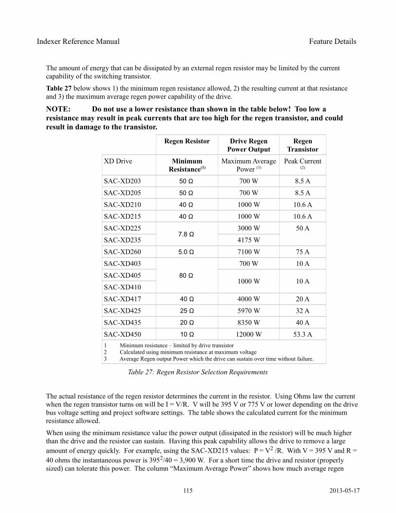
Indexer Reference Manual Feature Details
The amount of energy that can be dissipated by an external regen resistor may be limited by the current capability of the switching transistor.
Table 27 below shows 1) the minimum regen resistance allowed, 2) the resulting current at that resistance and 3) the maximum average regen power capability of the drive.
NOTE: Do not use a lower resistance than shown in the table below! Too low a resistance may result in peak currents that are too high for the regen transistor, and could result in damage to the transistor.
Regen Resistor Drive Regen Power Output
Regen Transistor
XD Drive Minimum Resistance(1)
Maximum Average Power (3)
Peak Current (2)
SAC-XD203 50 Ω 700 W 8.5 A
SAC-XD205 50 Ω 700 W 8.5 A
SAC-XD210 40 Ω 1000 W 10.6 A
SAC-XD215 40 Ω 1000 W 10.6 A
SAC-XD2257.8 Ω
3000 W 50 A
SAC-XD235 4175 W
SAC-XD260 5.0 Ω 7100 W 75 A
SAC-XD403
80 Ω
700 W 10 A
SAC-XD4051000 W 10 A
SAC-XD410
SAC-XD417 40 Ω 4000 W 20 A
SAC-XD425 25 Ω 5970 W 32 A
SAC-XD435 20 Ω 8350 W 40 A
SAC-XD450 10 Ω 12000 W 53.3 A1 Minimum resistance – limited by drive transistor2 Calculated using minimum resistance at maximum voltage3 Average Regen output Power which the drive can sustain over time without failure.
Table 27: Regen Resistor Selection Requirements
The actual resistance of the regen resistor determines the current in the resistor. Using Ohms law the current when the regen transistor turns on will be I = V/R. V will be 395 V or 775 V or lower depending on the drive bus voltage setting and project software settings. The table shows the calculated current for the minimum resistance allowed.
When using the minimum resistance value the power output (dissipated in the resistor) will be much higher than the drive and the resistor can sustain. Having this peak capability allows the drive to remove a large amount of energy quickly. For example, using the SAC-XD215 values: P = V2 /R. With V = 395 V and R = 40 ohms the instantaneous power is 3952/40 = 3,900 W. For a short time the drive and resistor (properly sized) can tolerate this power. The column “Maximum Average Power” shows how much average regen
115 2013-05-17
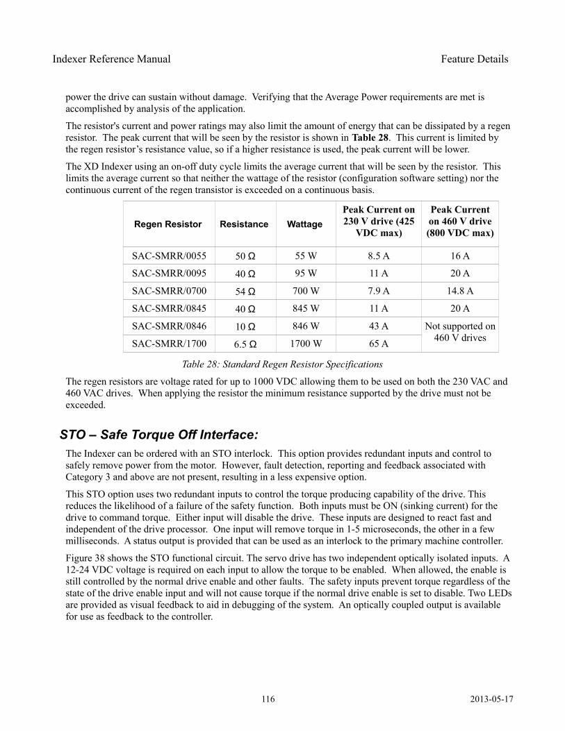
Indexer Reference Manual Feature Details
power the drive can sustain without damage. Verifying that the Average Power requirements are met is accomplished by analysis of the application.
The resistor's current and power ratings may also limit the amount of energy that can be dissipated by a regen resistor. The peak current that will be seen by the resistor is shown in Table 28. This current is limited by the regen resistor’s resistance value, so if a higher resistance is used, the peak current will be lower.
The XD Indexer using an on-off duty cycle limits the average current that will be seen by the resistor. This limits the average current so that neither the wattage of the resistor (configuration software setting) nor the continuous current of the regen transistor is exceeded on a continuous basis.
Regen Resistor Resistance Wattage Peak Current on 230 V drive (425
VDC max)
Peak Current on 460 V drive (800 VDC max)
SAC-SMRR/0055 50 Ω 55 W 8.5 A 16 A
SAC-SMRR/0095 40 Ω 95 W 11 A 20 A
SAC-SMRR/0700 54 Ω 700 W 7.9 A 14.8 A
SAC-SMRR/0845 40 Ω 845 W 11 A 20 A
SAC-SMRR/0846 10 Ω 846 W 43 A Not supported on 460 V drivesSAC-SMRR/1700 6.5 Ω 1700 W 65 A
Table 28: Standard Regen Resistor Specifications
The regen resistors are voltage rated for up to 1000 VDC allowing them to be used on both the 230 VAC and 460 VAC drives. When applying the resistor the minimum resistance supported by the drive must not be exceeded.
STO – Safe Torque Off Interface: The Indexer can be ordered with an STO interlock. This option provides redundant inputs and control to safely remove power from the motor. However, fault detection, reporting and feedback associated with Category 3 and above are not present, resulting in a less expensive option.
This STO option uses two redundant inputs to control the torque producing capability of the drive. This reduces the likelihood of a failure of the safety function. Both inputs must be ON (sinking current) for the drive to command torque. Either input will disable the drive. These inputs are designed to react fast and independent of the drive processor. One input will remove torque in 1-5 microseconds, the other in a few milliseconds. A status output is provided that can be used as an interlock to the primary machine controller.
Figure 38 shows the STO functional circuit. The servo drive has two independent optically isolated inputs. A 12-24 VDC voltage is required on each input to allow the torque to be enabled. When allowed, the enable is still controlled by the normal drive enable and other faults. The safety inputs prevent torque regardless of the state of the drive enable input and will not cause torque if the normal drive enable is set to disable. Two LEDs are provided as visual feedback to aid in debugging of the system. An optically coupled output is available for use as feedback to the controller.
116 2013-05-17
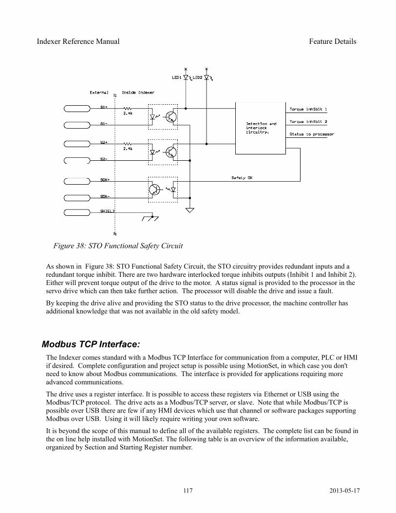
Indexer Reference Manual Feature Details
As shown in Figure 38: STO Functional Safety Circuit, the STO circuitry provides redundant inputs and a redundant torque inhibit. There are two hardware interlocked torque inhibits outputs (Inhibit 1 and Inhibit 2). Either will prevent torque output of the drive to the motor. A status signal is provided to the processor in the servo drive which can then take further action. The processor will disable the drive and issue a fault.
By keeping the drive alive and providing the STO status to the drive processor, the machine controller has additional knowledge that was not available in the old safety model.
Modbus TCP Interface: The Indexer comes standard with a Modbus TCP Interface for communication from a computer, PLC or HMI if desired. Complete configuration and project setup is possible using MotionSet, in which case you don't need to know about Modbus communications. The interface is provided for applications requiring more advanced communications.
The drive uses a register interface. It is possible to access these registers via Ethernet or USB using the Modbus/TCP protocol. The drive acts as a Modbus/TCP server, or slave. Note that while Modbus/TCP is possible over USB there are few if any HMI devices which use that channel or software packages supporting Modbus over USB. Using it will likely require writing your own software.
It is beyond the scope of this manual to define all of the available registers. The complete list can be found in the on line help installed with MotionSet. The following table is an overview of the information available, organized by Section and Starting Register number.
117 2013-05-17
Figure 38: STO Functional Safety Circuit
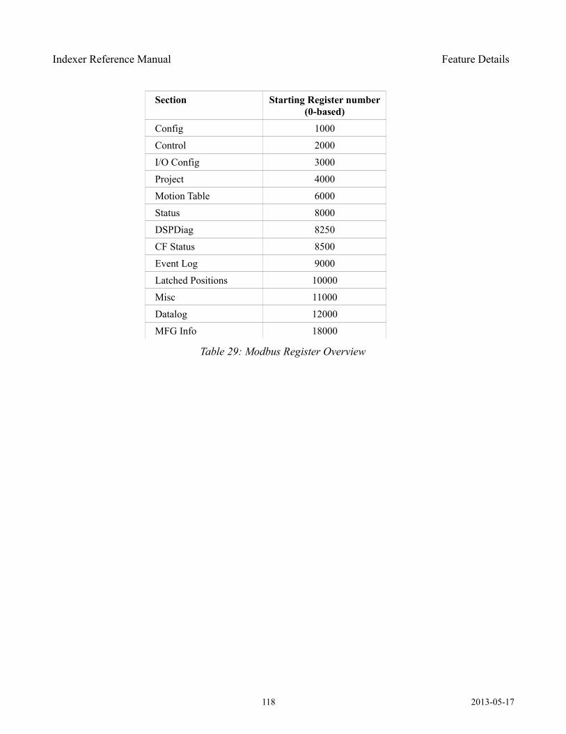
Indexer Reference Manual Feature Details
Section Starting Register number (0-based)
Config 1000
Control 2000
I/O Config 3000
Project 4000
Motion Table 6000
Status 8000
DSPDiag 8250
CF Status 8500
Event Log 9000
Latched Positions 10000
Misc 11000
Datalog 12000
MFG Info 18000
Table 29: Modbus Register Overview
118 2013-05-17
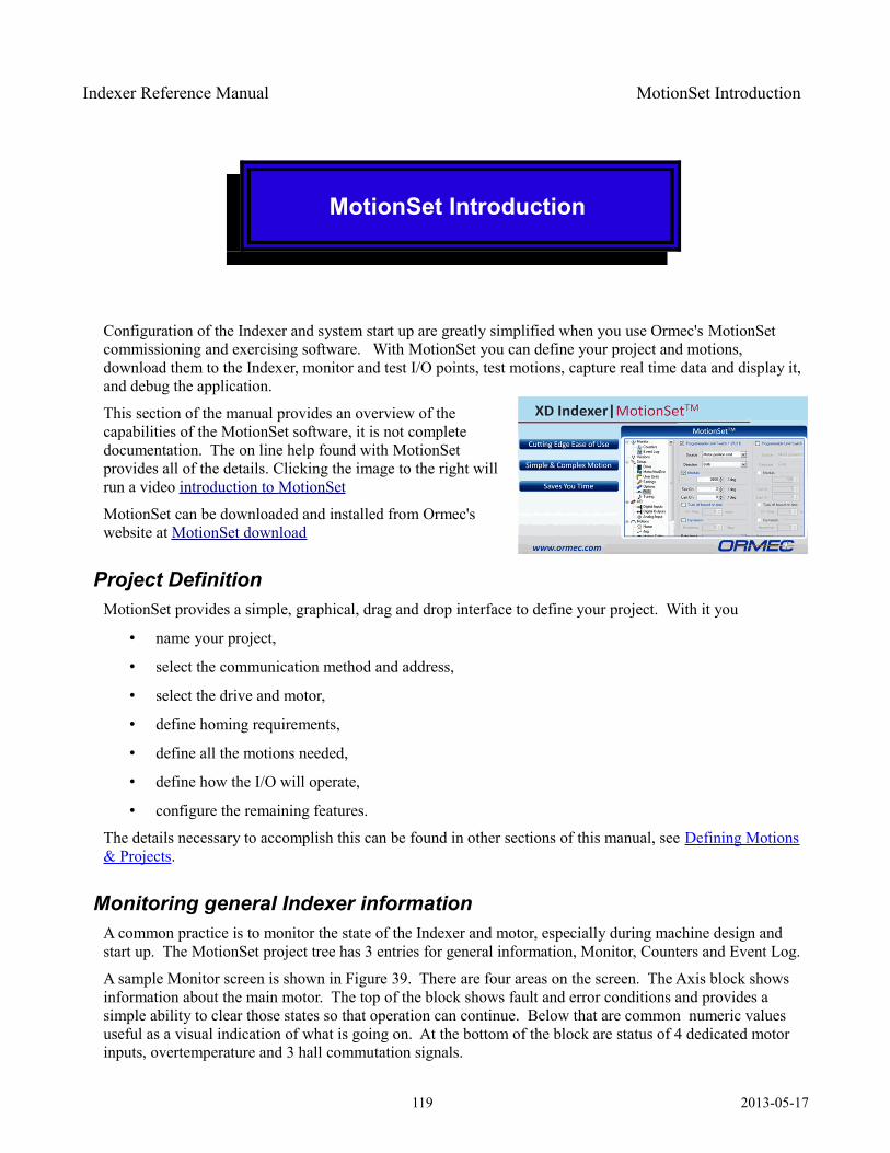
Indexer Reference Manual MotionSet Introduction
MotionSet Introduction
Configuration of the Indexer and system start up are greatly simplified when you use Ormec's MotionSet commissioning and exercising software. With MotionSet you can define your project and motions, download them to the Indexer, monitor and test I/O points, test motions, capture real time data and display it, and debug the application.
This section of the manual provides an overview of the capabilities of the MotionSet software, it is not complete documentation. The on line help found with MotionSet provides all of the details. Clicking the image to the right will run a video introduction to MotionSet
MotionSet can be downloaded and installed from Ormec's website at MotionSet download
Project DefinitionMotionSet provides a simple, graphical, drag and drop interface to define your project. With it you
• name your project,
• select the communication method and address,
• select the drive and motor,
• define homing requirements,
• define all the motions needed,
• define how the I/O will operate,
• configure the remaining features.
The details necessary to accomplish this can be found in other sections of this manual, see Defining Motions& Projects.
Monitoring general Indexer informationA common practice is to monitor the state of the Indexer and motor, especially during machine design and start up. The MotionSet project tree has 3 entries for general information, Monitor, Counters and Event Log.
A sample Monitor screen is shown in Figure 39. There are four areas on the screen. The Axis block shows information about the main motor. The top of the block shows fault and error conditions and provides a simple ability to clear those states so that operation can continue. Below that are common numeric values useful as a visual indication of what is going on. At the bottom of the block are status of 4 dedicated motor inputs, overtemperature and 3 hall commutation signals.
119 2013-05-17
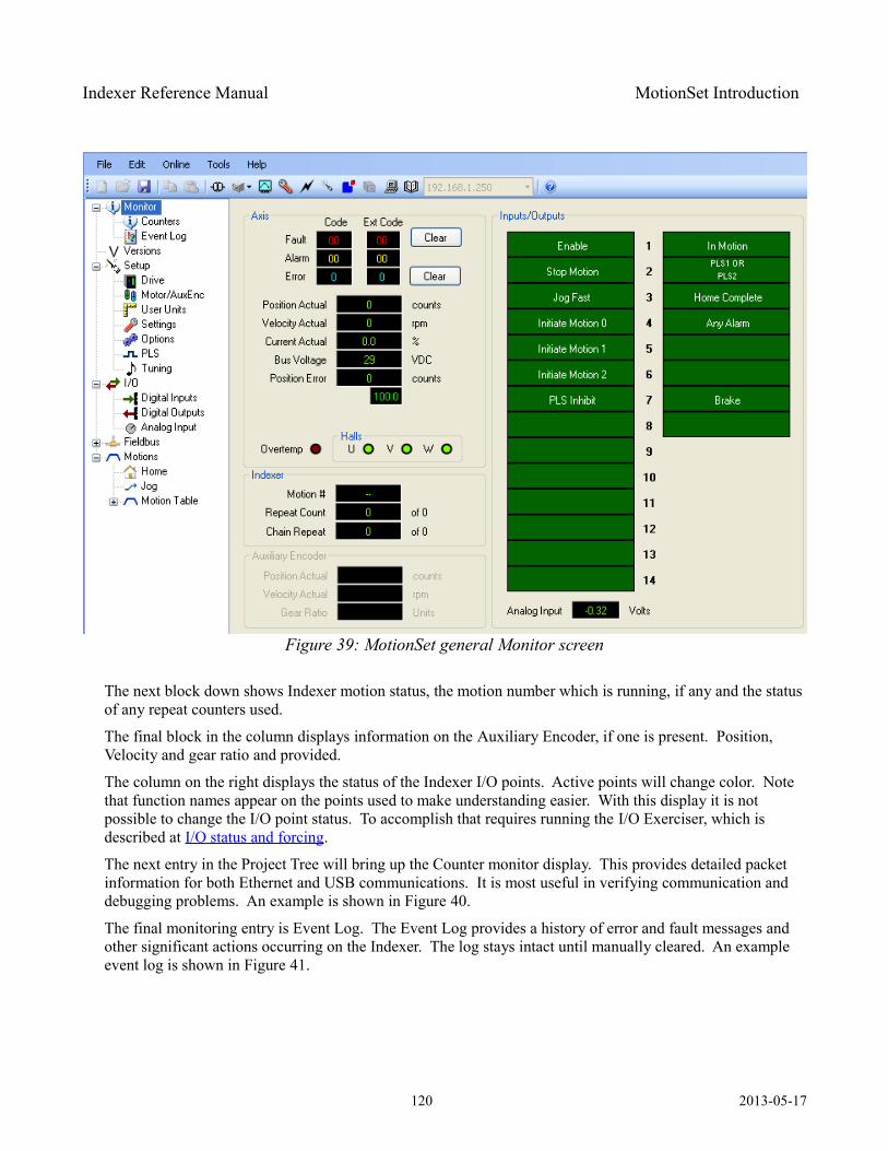
Indexer Reference Manual MotionSet Introduction
The next block down shows Indexer motion status, the motion number which is running, if any and the status of any repeat counters used.
The final block in the column displays information on the Auxiliary Encoder, if one is present. Position, Velocity and gear ratio and provided.
The column on the right displays the status of the Indexer I/O points. Active points will change color. Note that function names appear on the points used to make understanding easier. With this display it is not possible to change the I/O point status. To accomplish that requires running the I/O Exerciser, which is described at I/O status and forcing.
The next entry in the Project Tree will bring up the Counter monitor display. This provides detailed packet information for both Ethernet and USB communications. It is most useful in verifying communication and debugging problems. An example is shown in Figure 40.
The final monitoring entry is Event Log. The Event Log provides a history of error and fault messages and other significant actions occurring on the Indexer. The log stays intact until manually cleared. An example event log is shown in Figure 41.
120 2013-05-17
Figure 39: MotionSet general Monitor screen
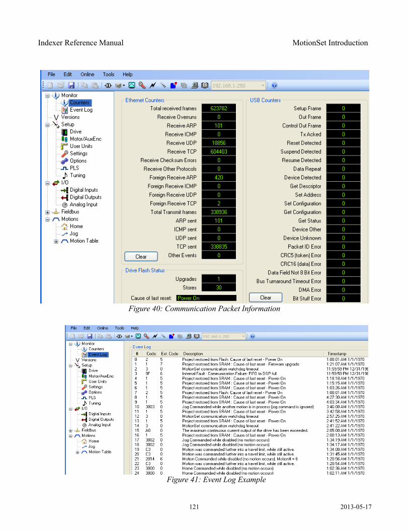
Indexer Reference Manual MotionSet Introduction
121 2013-05-17
Figure 40: Communication Packet Information
Figure 41: Event Log Example
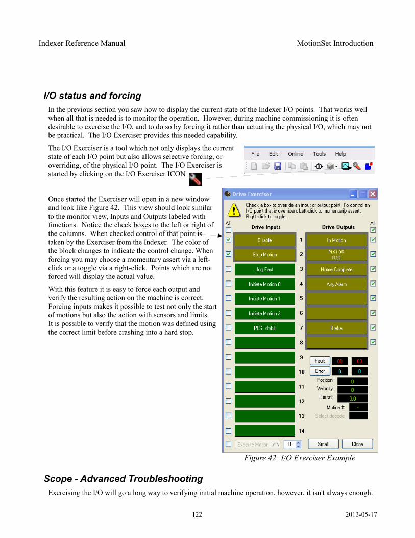
Indexer Reference Manual MotionSet Introduction
I/O status and forcingIn the previous section you saw how to display the current state of the Indexer I/O points. That works well when all that is needed is to monitor the operation. However, during machine commissioning it is often desirable to exercise the I/O, and to do so by forcing it rather than actuating the physical I/O, which may not be practical. The I/O Exerciser provides this needed capability.
The I/O Exerciser is a tool which not only displays the current state of each I/O point but also allows selective forcing, or overriding, of the physical I/O point. The I/O Exerciser is started by clicking on the I/O Exerciser ICON
Once started the Exerciser will open in a new window and look like Figure 42. This view should look similar to the monitor view, Inputs and Outputs labeled with functions. Notice the check boxes to the left or right of the columns. When checked control of that point is taken by the Exerciser from the Indexer. The color of the block changes to indicate the control change. When forcing you may choose a momentary assert via a left-click or a toggle via a right-click. Points which are not forced will display the actual value.
With this feature it is easy to force each output and verify the resulting action on the machine is correct. Forcing inputs makes it possible to test not only the start of motions but also the action with sensors and limits. It is possible to verify that the motion was defined using the correct limit before crashing into a hard stop.
Scope - Advanced TroubleshootingExercising the I/O will go a long way to verifying initial machine operation, however, it isn't always enough.
122 2013-05-17
Figure 42: I/O Exerciser Example
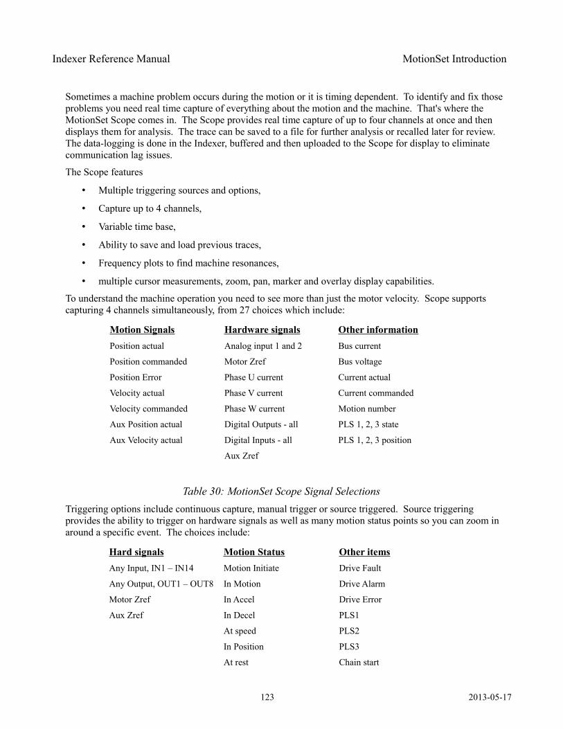
Indexer Reference Manual MotionSet Introduction
Sometimes a machine problem occurs during the motion or it is timing dependent. To identify and fix those problems you need real time capture of everything about the motion and the machine. That's where the MotionSet Scope comes in. The Scope provides real time capture of up to four channels at once and then displays them for analysis. The trace can be saved to a file for further analysis or recalled later for review. The data-logging is done in the Indexer, buffered and then uploaded to the Scope for display to eliminate communication lag issues.
The Scope features
• Multiple triggering sources and options,
• Capture up to 4 channels,
• Variable time base,
• Ability to save and load previous traces,
• Frequency plots to find machine resonances,
• multiple cursor measurements, zoom, pan, marker and overlay display capabilities.
To understand the machine operation you need to see more than just the motor velocity. Scope supports capturing 4 channels simultaneously, from 27 choices which include:
Motion Signals Hardware signals Other informationPosition actual Analog input 1 and 2 Bus current
Position commanded Motor Zref Bus voltage
Position Error Phase U current Current actual
Velocity actual Phase V current Current commanded
Velocity commanded Phase W current Motion number
Aux Position actual Digital Outputs - all PLS 1, 2, 3 state
Aux Velocity actual Digital Inputs - all PLS 1, 2, 3 position
Aux Zref
Table 30: MotionSet Scope Signal SelectionsTriggering options include continuous capture, manual trigger or source triggered. Source triggering provides the ability to trigger on hardware signals as well as many motion status points so you can zoom in around a specific event. The choices include:
Hard signals Motion Status Other itemsAny Input, IN1 – IN14 Motion Initiate Drive Fault
Any Output, OUT1 – OUT8 In Motion Drive Alarm
Motor Zref In Accel Drive Error
Aux Zref In Decel PLS1
At speed PLS2
In Position PLS3
At rest Chain start
123 2013-05-17
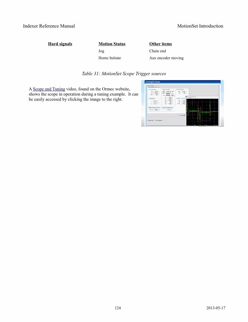
Indexer Reference Manual MotionSet Introduction
Hard signals Motion Status Other itemsJog Chain end
Home Initiate Aux encoder moving
Table 31: MotionSet Scope Trigger sources
A Scope and Tuning video, found on the Ormec website, shows the scope in operation during a tuning example. It can be easily accessed by clicking the image to the right.
124 2013-05-17
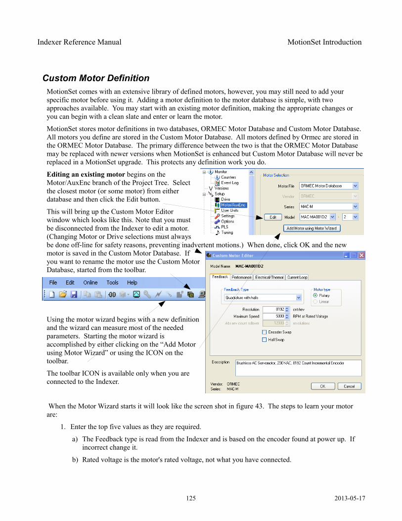
Indexer Reference Manual MotionSet Introduction
Custom Motor DefinitionMotionSet comes with an extensive library of defined motors, however, you may still need to add your specific motor before using it. Adding a motor definition to the motor database is simple, with two approaches available. You may start with an existing motor definition, making the appropriate changes or you can begin with a clean slate and enter or learn the motor.
MotionSet stores motor definitions in two databases, ORMEC Motor Database and Custom Motor Database. All motors you define are stored in the Custom Motor Database. All motors defined by Ormec are stored in the ORMEC Motor Database. The primary difference between the two is that the ORMEC Motor Database may be replaced with newer versions when MotionSet is enhanced but Custom Motor Database will never be replaced in a MotionSet upgrade. This protects any definition work you do.
Editing an existing motor begins on the Motor/AuxEnc branch of the Project Tree. Select the closest motor (or some motor) from either database and then click the Edit button.
This will bring up the Custom Motor Editor window which looks like this. Note that you must be disconnected from the Indexer to edit a motor. (Changing Motor or Drive selections must always be done off-line for safety reasons, preventing inadvertent motions.) When done, click OK and the new motor is saved in the Custom Motor Database. If you want to rename the motor use the Custom Motor Database, started from the toolbar.
Using the motor wizard begins with a new definition and the wizard can measure most of the needed parameters. Starting the motor wizard is accomplished by either clicking on the “Add Motor using Motor Wizard” or using the ICON on the toolbar.
The toolbar ICON is available only when you are connected to the Indexer.
When the Motor Wizard starts it will look like the screen shot in figure 43. The steps to learn your motor are:
1. Enter the top five values as they are required.
a) The Feedback type is read from the Indexer and is based on the encoder found at power up. If incorrect change it.
b) Rated voltage is the motor's rated voltage, not what you have connected.
125 2013-05-17
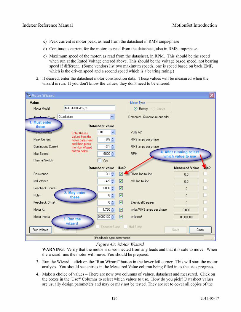
Indexer Reference Manual MotionSet Introduction
c) Peak current is motor peak, as read from the datasheet in RMS amps/phase
d) Continuous current for the motor, as read from the datasheet, also in RMS amp/phase.
e) Maximum speed of the motor, as read from the datasheet, in RPM. This should be the speed when run at the Rated Voltage entered above. This should be the voltage based speed, not bearing speed if different. (Some vendors list two maximum speeds, one is speed based on back EMF, which is the driven speed and a second speed which is a bearing rating.)
2. If desired, enter the datasheet motor construction data. These values will be measured when the wizard is run. If you don't know the values, they don't need to be entered.
WARNING: Verify that the motor is disconnected from any loads and that it is safe to move. When the wizard runs the motor will move. You should be prepared.
3. Run the Wizard – click on the “Run Wizard” button in the lower left corner. This will start the motor analysis. You should see entries in the Measured Value column being filled in as the tests progress.
4. Make a choice of values – There are now two columns of values, datasheet and measured. Click on the boxes in the 'Use?' Columns to select which values to use. How do you pick? Datasheet values are usually design parameters and may or may not be tested. They are set to cover all copies of the
126 2013-05-17
Figure 43: Motor Wizard

Indexer Reference Manual MotionSet Introduction
motor, allowing for inevitable production variations. The measured values apply to this specific motor. If it is on the fringe of the manufacturers range then it may not be completely representative of all copies of the motor. The selection depends on how much the values differ, if you plan on using more of these motors or if this is a single application.
127 2013-05-17

Indexer Reference Manual MotionSet Introduction
Fieldbus Support
Many applications require or can be enhanced by the addition of real time communication of parameters and status. Such communication allows a HMI to continuously display status such as position or speed or to change the parameters of a motion as product variations come down the line. It allows a PLC or supervisory computer to change motion parameters as changes in the machine occur.
Though real time communication is possible using the USB or standard Ethernet ports improvements can be achieved using an industrial Fieldbus. A Fieldbus offers a defined structure and protocol making implementation simpler and quicker because of the established software base. Most PLCs and supervisory computers either have or can have a Fieldbus interface installed, eliminating the need to define and implement all of the communication support.
The ORMEC Indexer supports a number of Fieldbus interfaces which can be included in the Indexer when ordered. See section Decoding Model Numbers for ordering information.
Ethernet/IP: Ethernet/IP (Ethernet Industrial Protocol) is a standard industrial network protocol maintained by an international organization called ODVA (Open DeviceNet Vendors Assoc.) It is designed for use in industrial automation. The Ethernet/IP protocol is built on CIP (Common Industrial Protocol) which in this case operates on a standard TCP/IP stack. There is no special hardware required for Ethernet/IP, it is compatible with existing Ethernet infrastructure (cabling, switches, etc).
When the Indexer is purchased with Ethernet/IP installed, you simply need to connect an Ethernet cable from the Indexer J3 connector to a network that has an Ethernet/IP scanner (often a PLC or supervisory computer). Using MotionSet, Indexer parameters are configured using a graphical drag and drop interface to be visible on the Ethernet/IP network. When the scanner device is configured with the same parameter mapping, values are updated automatically between the scanner and Indexer. You are insulated from the details and complexities of communications between the devices.
OverviewTransfer of information is accomplished by defining 2 packets of information, one contains information sent to the Indexer and the other has information from the Indexer. Each packet is defined as a list of Indexer parameters. That mapping defines the location to get information to place in the outgoing packet or the location to store information found in the incoming packet. The packets are transferred and the software on the opposite equipment uses the mapping to reverse the process. The scanner needs to be configured with a matching set of parameters in the packet and is automatically updated in a Class 1 connection to the Indexer
Setup is a 3 step process. The first step is to install or have installed the hardware and protocol software in both pieces of equipment. Second step is to define the mapping of Indexer registers to the input and output registers and load those definitions into the Indexer. The third step is to configure the Ethernet/IP scanner to
128 2013-05-17
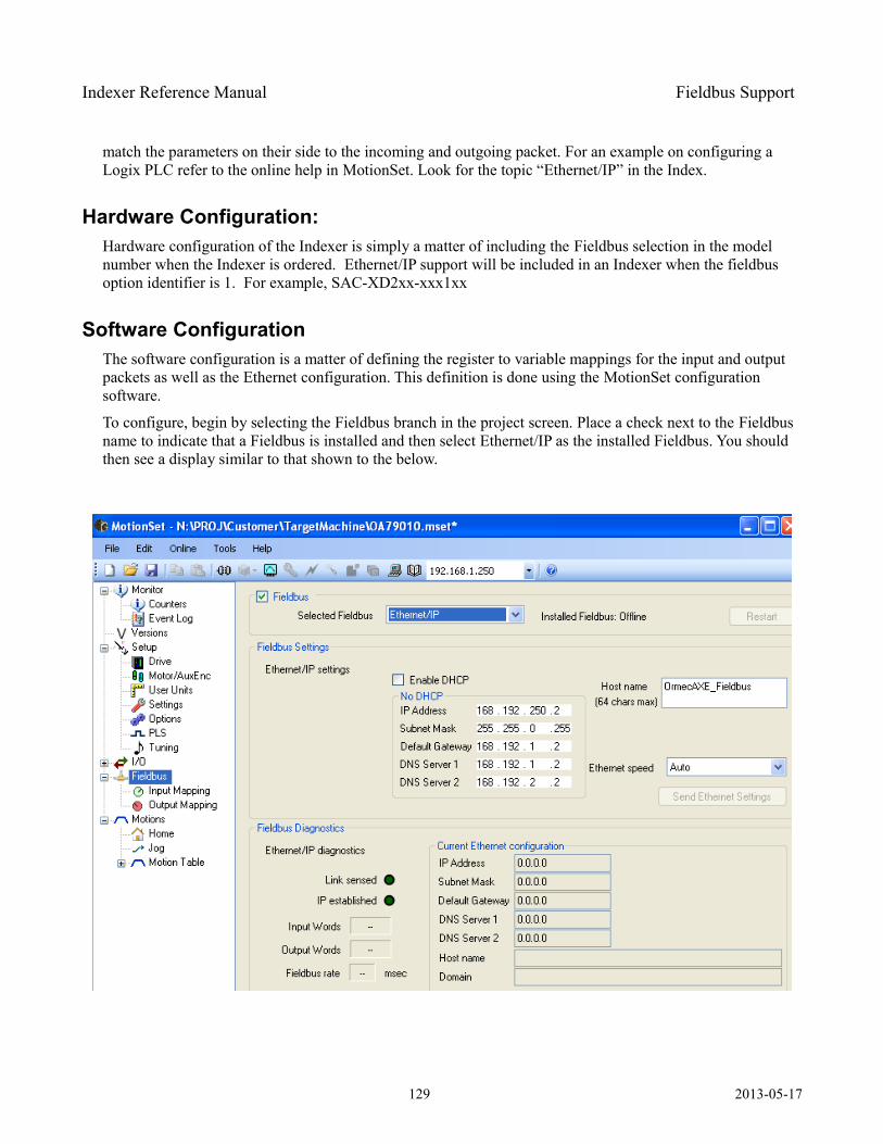
Indexer Reference Manual Fieldbus Support
match the parameters on their side to the incoming and outgoing packet. For an example on configuring a Logix PLC refer to the online help in MotionSet. Look for the topic “Ethernet/IP” in the Index.
Hardware Configuration:Hardware configuration of the Indexer is simply a matter of including the Fieldbus selection in the model number when the Indexer is ordered. Ethernet/IP support will be included in an Indexer when the fieldbus option identifier is 1. For example, SAC-XD2xx-xxx1xx
Software ConfigurationThe software configuration is a matter of defining the register to variable mappings for the input and output packets as well as the Ethernet configuration. This definition is done using the MotionSet configuration software.
To configure, begin by selecting the Fieldbus branch in the project screen. Place a check next to the Fieldbus name to indicate that a Fieldbus is installed and then select Ethernet/IP as the installed Fieldbus. You should then see a display similar to that shown to the below.
129 2013-05-17
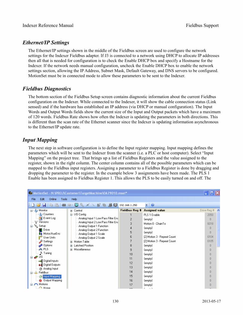
Indexer Reference Manual Fieldbus Support
Ethernet/IP SettingsThe Ethernet/IP settings shown in the middle of the Fieldbus screen are used to configure the network settings for the Indexer Fieldbus adapter. If J3 is connected to a network using DHCP to allocate IP addresses then all that is needed for configuration is to check the Enable DHCP box and specify a Hostname for the Indexer. If the network needs manual configuration, uncheck the Enable DHCP box to enable the network settings section, allowing the IP Address, Subnet Mask, Default Gateway, and DNS servers to be configured. MotionSet must be in connected mode to allow these parameters to be sent to the Indexer.
Fieldbus DiagnosticsThe bottom section of the Fieldbus Setup screen contains diagnostic information about the current Fieldbus configuration on the Indexer. While connected to the Indexer, it will show the cable connection status (Link sensed) and if the hardware has established an IP address (via DHCP or manual configuration). The Input Words and Output Words fields show the current size of the Input and Output packets which have a maximum of 120 words. Fieldbus Rate shows how often the Indexer is updating the parameters in both directions. This is different than the scan rate of the Ethernet scanner since the Indexer is updating information asynchronous to the Ethernet/IP update rate.
Input MappingThe next step in software configuration is to define the Input register mapping. Input mapping defines the parameters which will be sent to the Indexer from the scanner (i.e. a PLC or host computer). Select “Input Mapping” on the project tree. That brings up a list of Fieldbus Registers and the value assigned to the register, shown in the right column. The center column contains all of the possible parameters which can be mapped to the Fieldbus input registers. Assigning a parameter to a Fieldbus Register is done by dragging and dropping the parameter to the register. In the example below 3 assignments have been made. The PLS 1 Enable has been assigned to Fieldbus Register 1. This allows the PLS to be easily turned on and off. The
130 2013-05-17
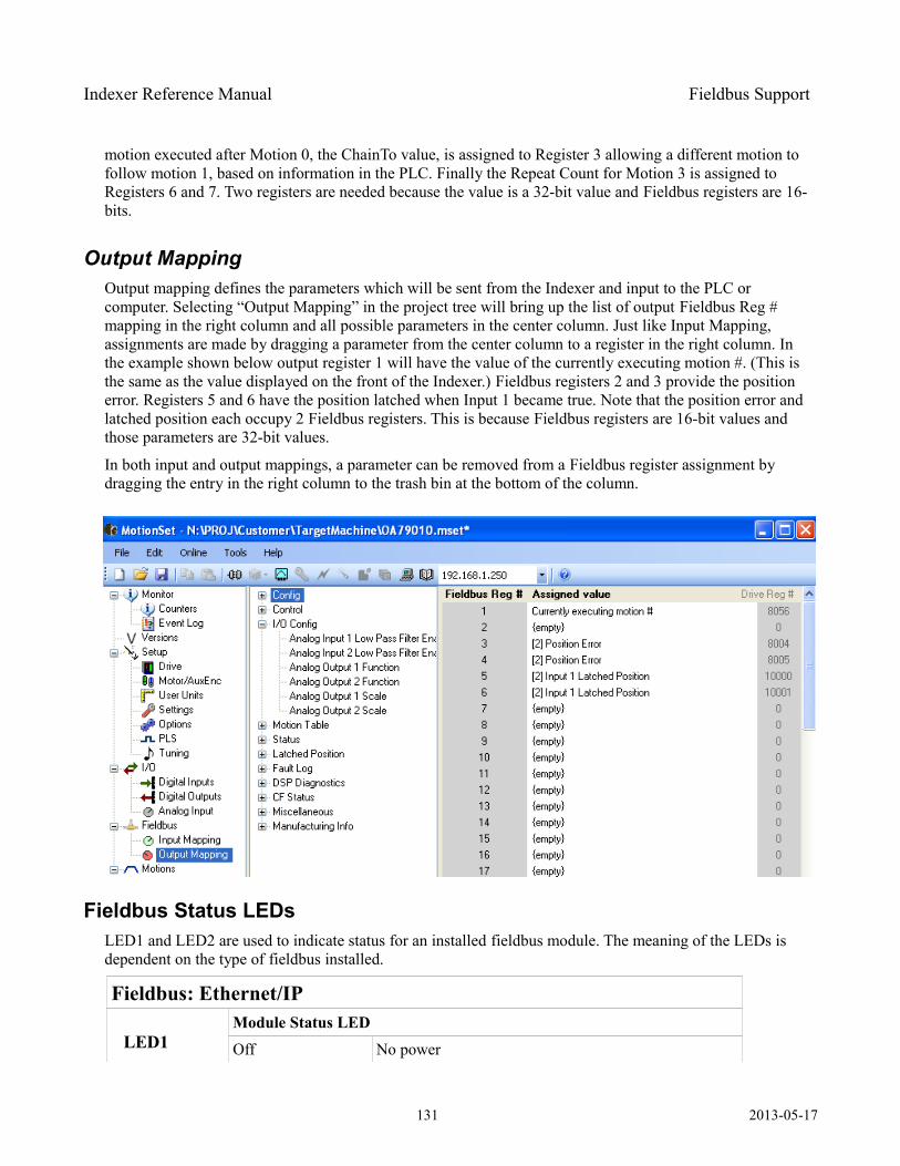
Indexer Reference Manual Fieldbus Support
motion executed after Motion 0, the ChainTo value, is assigned to Register 3 allowing a different motion to follow motion 1, based on information in the PLC. Finally the Repeat Count for Motion 3 is assigned to Registers 6 and 7. Two registers are needed because the value is a 32-bit value and Fieldbus registers are 16-bits.
Output MappingOutput mapping defines the parameters which will be sent from the Indexer and input to the PLC or computer. Selecting “Output Mapping” in the project tree will bring up the list of output Fieldbus Reg # mapping in the right column and all possible parameters in the center column. Just like Input Mapping, assignments are made by dragging a parameter from the center column to a register in the right column. In the example shown below output register 1 will have the value of the currently executing motion #. (This is the same as the value displayed on the front of the Indexer.) Fieldbus registers 2 and 3 provide the position error. Registers 5 and 6 have the position latched when Input 1 became true. Note that the position error and latched position each occupy 2 Fieldbus registers. This is because Fieldbus registers are 16-bit values and those parameters are 32-bit values.
In both input and output mappings, a parameter can be removed from a Fieldbus register assignment by dragging the entry in the right column to the trash bin at the bottom of the column.
Fieldbus Status LEDsLED1 and LED2 are used to indicate status for an installed fieldbus module. The meaning of the LEDs is dependent on the type of fieldbus installed.
Fieldbus: Ethernet/IP
LED1Module Status LEDOff No power
131 2013-05-17
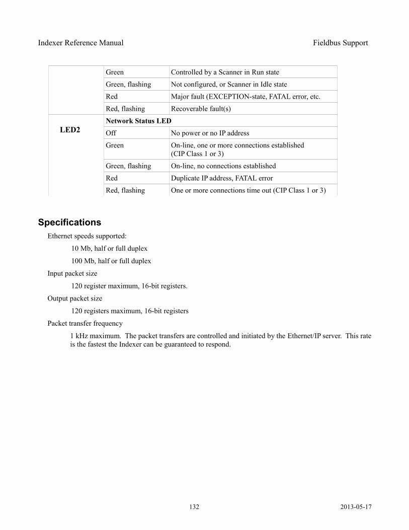
Indexer Reference Manual Fieldbus Support
Green Controlled by a Scanner in Run state
Green, flashing Not configured, or Scanner in Idle state
Red Major fault (EXCEPTION-state, FATAL error, etc.
Red, flashing Recoverable fault(s)
LED2Network Status LEDOff No power or no IP address
Green On-line, one or more connections established (CIP Class 1 or 3)
Green, flashing On-line, no connections established
Red Duplicate IP address, FATAL error
Red, flashing One or more connections time out (CIP Class 1 or 3)
SpecificationsEthernet speeds supported:
10 Mb, half or full duplex
100 Mb, half or full duplex
Input packet size
120 register maximum, 16-bit registers.
Output packet size
120 registers maximum, 16-bit registers
Packet transfer frequency
1 kHz maximum. The packet transfers are controlled and initiated by the Ethernet/IP server. This rate is the fastest the Indexer can be guaranteed to respond.
132 2013-05-17
Indexer Reference Manual Solving Problems
Solving Problems
Aka Troubleshooting
The first table in Solving Problems is for general problems.
The second table is a list of Error codes and what actions to take when they happen.
133 2013-05-17

Indexer Reference Manual Solving Problems
What went wrong When did it happen What to do or how to fix it
Applied power and nothing happened. No lights or activity.
When power applied.
DC Input: 1) Verify the voltage on TB1.2) check model number for -*A****. This is an AC input drive. The DC connections on TB1 are now an output and are diode protected. Applying power will be blocked by the diode. Switch to AC input on TB2.
AC Input: 1) Verify control power connections are on pins r & t of TB2 and that the voltage is above 85 VAC. 2) check model number for -*A*****. If the A is missing (then a D) this is a DC input drive. No AC control power circuitry exists. Switch to DC input on TB1.
Closed input and motion didn't happen
Verify that the Indexer is enabled. This is indicated by the right decimal point in the status display. No motion can be executed while disabled.
If working from the I/O exerciser 1) make sure that you have turned on override by checking the box next to the input, 2) make sure to hold the mouse click long enough.
If using physical I/O 1) use MotionSet or the I/O exerciser to monitor the inputs and verify that the Indexer is seeing the input, 2) if the input is working check that the input is mapped to Initiate the motion and 3) verify that a motion is defined at the motion number which is initiated.
If a motion is already running then another motion cannot be started while the motion is in process. This includes the dwell time at the end of the motion previous motion. Check the dwell time on all motions.
Ethernet won't connect After changing connections
When configuring more than one Indexer you will likely move your Ethernet cable from one unit to another. Microsoft windows will sometimes have a problem when you try to connect a second device with a different MAC address using the same IP address. (Each Indexer has a different hardware physical address, called a MAC address.) You can clear the Windows table by executing the following command in a command window. arp -d 192.168.1.250(Use Start – Run and then cmd or command to open a command window.)
Motion didn't run at expected speed.
The motion velocity will be automatically reduced if the move isn't long enough to allow the motor to reach the input speed. This primarily happens with absolute moves (move to an absolute position) when the distance to travel is short.
Table 32: Troubleshooting Guide
134 2013-05-17

Indexer Reference Manual Solving Problems
The Fault Code table provides an understanding of the Fault Codes which may be displayed on the Indexer. A Fault is defined as a problem which is severe enough or has a safety risk such that motion cannot be initiated or continued. This differs from a warning where operation may safely continue.
All Faults will disable the Indexer. Energizing the output power and control of the motor cannot happen due to the severity of the problem.
Faults are displayed on the 2-digit display near the upper left corner of the Indexer. All faults are 2 digit numbers and begin at a value of 70. The value 70 is larger than an valid motion number. During normal operation the Indexer will display the running motion, which is a number from 0 to 32. This is normal and does not indicate an error.
Some of the Faults have an extended code which provides additional detail about the problem. Faults displayed on the Indexer show a main fault code followed by an underscore and extended code number.
135 2013-05-17
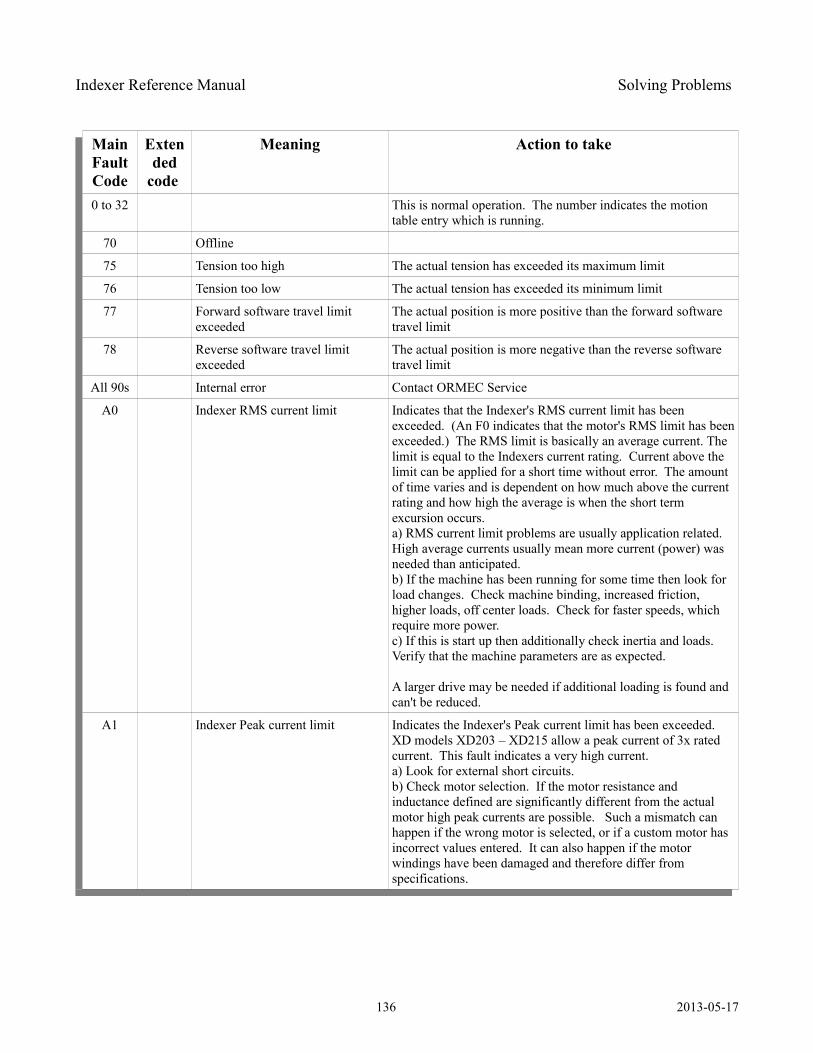
Indexer Reference Manual Solving Problems
Main Fault Code
Extended
code
Meaning Action to take
0 to 32 This is normal operation. The number indicates the motion table entry which is running.
70 Offline
75 Tension too high The actual tension has exceeded its maximum limit
76 Tension too low The actual tension has exceeded its minimum limit
77 Forward software travel limit exceeded
The actual position is more positive than the forward software travel limit
78 Reverse software travel limit exceeded
The actual position is more negative than the reverse software travel limit
All 90s Internal error Contact ORMEC Service
A0 Indexer RMS current limit Indicates that the Indexer's RMS current limit has been exceeded. (An F0 indicates that the motor's RMS limit has been exceeded.) The RMS limit is basically an average current. The limit is equal to the Indexers current rating. Current above the limit can be applied for a short time without error. The amount of time varies and is dependent on how much above the current rating and how high the average is when the short term excursion occurs.a) RMS current limit problems are usually application related. High average currents usually mean more current (power) was needed than anticipated.b) If the machine has been running for some time then look for load changes. Check machine binding, increased friction, higher loads, off center loads. Check for faster speeds, which require more power.c) If this is start up then additionally check inertia and loads. Verify that the machine parameters are as expected.
A larger drive may be needed if additional loading is found and can't be reduced.
A1 Indexer Peak current limit Indicates the Indexer's Peak current limit has been exceeded. XD models XD203 – XD215 allow a peak current of 3x rated current. This fault indicates a very high current.a) Look for external short circuits.b) Check motor selection. If the motor resistance and inductance defined are significantly different from the actual motor high peak currents are possible. Such a mismatch can happen if the wrong motor is selected, or if a custom motor has incorrect values entered. It can also happen if the motor windings have been damaged and therefore differ from specifications.
136 2013-05-17
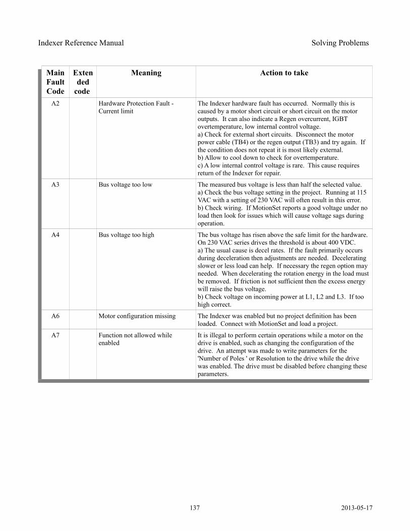
Indexer Reference Manual Solving Problems
Main Fault Code
Extended
code
Meaning Action to take
A2 Hardware Protection Fault - Current limit
The Indexer hardware fault has occurred. Normally this is caused by a motor short circuit or short circuit on the motor outputs. It can also indicate a Regen overcurrent, IGBT overtemperature, low internal control voltage.a) Check for external short circuits. Disconnect the motor power cable (TB4) or the regen output (TB3) and try again. If the condition does not repeat it is most likely external.b) Allow to cool down to check for overtemperature.c) A low internal control voltage is rare. This cause requires return of the Indexer for repair.
A3 Bus voltage too low The measured bus voltage is less than half the selected value. a) Check the bus voltage setting in the project. Running at 115 VAC with a setting of 230 VAC will often result in this error.b) Check wiring. If MotionSet reports a good voltage under no load then look for issues which will cause voltage sags during operation.
A4 Bus voltage too high The bus voltage has risen above the safe limit for the hardware. On 230 VAC series drives the threshold is about 400 VDC.a) The usual cause is decel rates. If the fault primarily occurs during deceleration then adjustments are needed. Decelerating slower or less load can help. If necessary the regen option may needed. When decelerating the rotation energy in the load must be removed. If friction is not sufficient then the excess energy will raise the bus voltage.b) Check voltage on incoming power at L1, L2 and L3. If too high correct.
A6 Motor configuration missing The Indexer was enabled but no project definition has been loaded. Connect with MotionSet and load a project.
A7 Function not allowed while enabled
It is illegal to perform certain operations while a motor on the drive is enabled, such as changing the configuration of the drive. An attempt was made to write parameters for the 'Number of Poles ' or Resolution to the drive while the drive was enabled. The drive must be disabled before changing these parameters.
137 2013-05-17
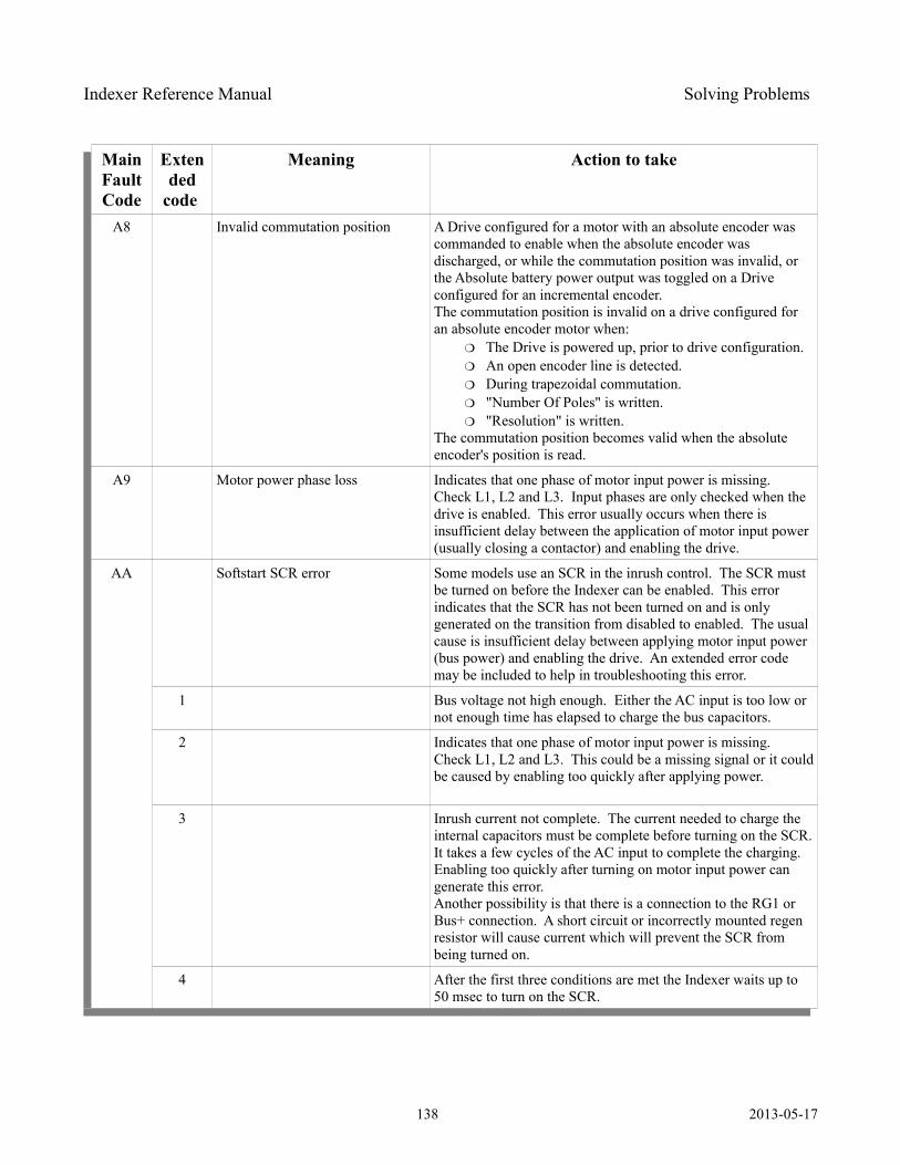
Indexer Reference Manual Solving Problems
Main Fault Code
Extended
code
Meaning Action to take
A8 Invalid commutation position A Drive configured for a motor with an absolute encoder was commanded to enable when the absolute encoder was discharged, or while the commutation position was invalid, or the Absolute battery power output was toggled on a Drive configured for an incremental encoder.The commutation position is invalid on a drive configured for an absolute encoder motor when:
The Drive is powered up, prior to drive configuration. An open encoder line is detected. During trapezoidal commutation. "Number Of Poles" is written. "Resolution" is written.
The commutation position becomes valid when the absolute encoder's position is read.
A9 Motor power phase loss Indicates that one phase of motor input power is missing. Check L1, L2 and L3. Input phases are only checked when the drive is enabled. This error usually occurs when there is insufficient delay between the application of motor input power (usually closing a contactor) and enabling the drive.
AA Softstart SCR error Some models use an SCR in the inrush control. The SCR must be turned on before the Indexer can be enabled. This error indicates that the SCR has not been turned on and is only generated on the transition from disabled to enabled. The usual cause is insufficient delay between applying motor input power (bus power) and enabling the drive. An extended error code may be included to help in troubleshooting this error.
1 Bus voltage not high enough. Either the AC input is too low or not enough time has elapsed to charge the bus capacitors.
2 Indicates that one phase of motor input power is missing. Check L1, L2 and L3. This could be a missing signal or it could be caused by enabling too quickly after applying power.
3 Inrush current not complete. The current needed to charge the internal capacitors must be complete before turning on the SCR. It takes a few cycles of the AC input to complete the charging. Enabling too quickly after turning on motor input power can generate this error.Another possibility is that there is a connection to the RG1 or Bus+ connection. A short circuit or incorrectly mounted regen resistor will cause current which will prevent the SCR from being turned on.
4 After the first three conditions are met the Indexer waits up to 50 msec to turn on the SCR.
138 2013-05-17
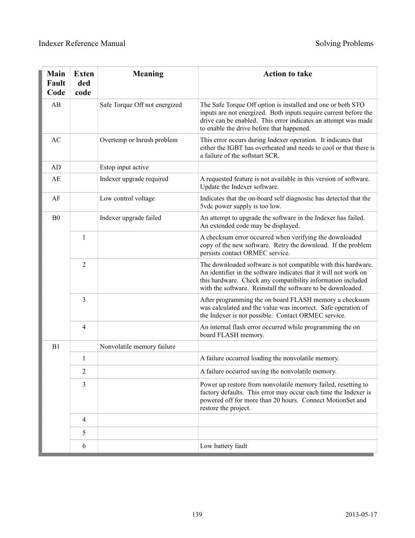
Indexer Reference Manual Solving Problems
Main Fault Code
Extended
code
Meaning Action to take
AB Safe Torque Off not energized The Safe Torque Off option is installed and one or both STO inputs are not energized. Both inputs require current before the drive can be enabled. This error indicates an attempt was made to enable the drive before that happened.
AC Overtemp or Inrush problem This error occurs during Indexer operation. It indicates that either the IGBT has overheated and needs to cool or that there is a failure of the softstart SCR.
AD Estop input active
AE Indexer upgrade required A requested feature is not available in this version of software. Update the Indexer software.
AF Low control voltage Indicates that the on-board self diagnostic has detected that the 5vdc power supply is too low.
B0 Indexer upgrade failed An attempt to upgrade the software in the Indexer has failed. An extended code may be displayed.
1 A checksum error occurred when verifying the downloaded copy of the new software. Retry the download. If the problem persists contact ORMEC service.
2 The downloaded software is not compatible with this hardware. An identifier in the software indicates that it will not work on this hardware. Check any compatibility information included with the software. Reinstall the software to be downloaded.
3 After programming the on board FLASH memory a checksum was calculated and the value was incorrect. Safe operation of the Indexer is not possible. Contact ORMEC service.
4 An internal flash error occurred while programming the on board FLASH memory.
B1 Nonvolatile memory failure
1 A failure occurred loading the nonvolatile memory.
2 A failure occurred saving the nonvolatile memory.
3 Power up restore from nonvolatile memory failed, resetting to factory defaults. This error may occur each time the Indexer is powered off for more than 20 hours. Connect MotionSet and restore the project.
4
5
6 Low battery fault
139 2013-05-17
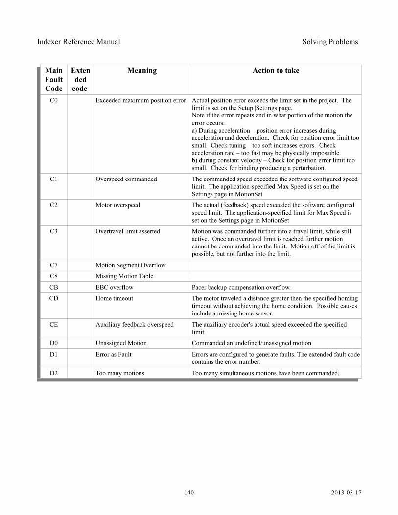
Indexer Reference Manual Solving Problems
Main Fault Code
Extended
code
Meaning Action to take
C0 Exceeded maximum position error Actual position error exceeds the limit set in the project. The limit is set on the Setup |Settings page.Note if the error repeats and in what portion of the motion the error occurs.a) During acceleration – position error increases during acceleration and deceleration. Check for position error limit too small. Check tuning – too soft increases errors. Check acceleration rate – too fast may be physically impossible.b) during constant velocity – Check for position error limit too small. Check for binding producing a perturbation.
C1 Overspeed commanded The commanded speed exceeded the software configured speed limit. The application-specified Max Speed is set on the Settings page in MotionSet
C2 Motor overspeed The actual (feedback) speed exceeded the software configured speed limit. The application-specified limit for Max Speed is set on the Settings page in MotionSet
C3 Overtravel limit asserted Motion was commanded further into a travel limit, while still active. Once an overtravel limit is reached further motion cannot be commanded into the limit. Motion off of the limit is possible, but not further into the limit.
C7 Motion Segment Overflow
C8 Missing Motion Table
CB EBC overflow Pacer backup compensation overflow.
CD Home timeout The motor traveled a distance greater then the specified homing timeout without achieving the home condition. Possible causes include a missing home sensor.
CE Auxiliary feedback overspeed The auxiliary encoder's actual speed exceeded the specified limit.
D0 Unassigned Motion Commanded an undefined/unassigned motion
D1 Error as Fault Errors are configured to generate faults. The extended fault code contains the error number.
D2 Too many motions Too many simultaneous motions have been commanded.
140 2013-05-17
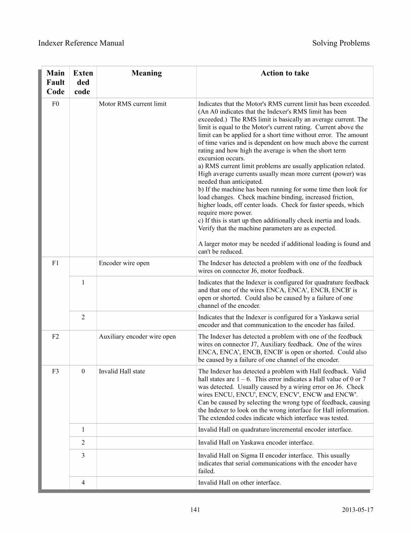
Indexer Reference Manual Solving Problems
Main Fault Code
Extended
code
Meaning Action to take
F0 Motor RMS current limit Indicates that the Motor's RMS current limit has been exceeded. (An A0 indicates that the Indexer's RMS limit has been exceeded.) The RMS limit is basically an average current. The limit is equal to the Motor's current rating. Current above the limit can be applied for a short time without error. The amount of time varies and is dependent on how much above the current rating and how high the average is when the short term excursion occurs.a) RMS current limit problems are usually application related. High average currents usually mean more current (power) was needed than anticipated.b) If the machine has been running for some time then look for load changes. Check machine binding, increased friction, higher loads, off center loads. Check for faster speeds, which require more power.c) If this is start up then additionally check inertia and loads. Verify that the machine parameters are as expected.
A larger motor may be needed if additional loading is found and can't be reduced.
F1 Encoder wire open The Indexer has detected a problem with one of the feedback wires on connector J6, motor feedback.
1 Indicates that the Indexer is configured for quadrature feedback and that one of the wires ENCA, ENCA', ENCB, ENCB' is open or shorted. Could also be caused by a failure of one channel of the encoder.
2 Indicates that the Indexer is configured for a Yaskawa serial encoder and that communication to the encoder has failed.
F2 Auxiliary encoder wire open The Indexer has detected a problem with one of the feedback wires on connector J7, Auxiliary feedback. One of the wires ENCA, ENCA', ENCB, ENCB' is open or shorted. Could also be caused by a failure of one channel of the encoder.
F3 0 Invalid Hall state The Indexer has detected a problem with Hall feedback. Valid hall states are 1 – 6. This error indicates a Hall value of 0 or 7 was detected. Usually caused by a wiring error on J6. Check wires ENCU, ENCU', ENCV, ENCV', ENCW and ENCW'.Can be caused by selecting the wrong type of feedback, causing the Indexer to look on the wrong interface for Hall information. The extended codes indicate which interface was tested.
1 Invalid Hall on quadrature/incremental encoder interface.
2 Invalid Hall on Yaskawa encoder interface.
3 Invalid Hall on Sigma II encoder interface. This usually indicates that serial communications with the encoder have failed.
4 Invalid Hall on other interface.
141 2013-05-17
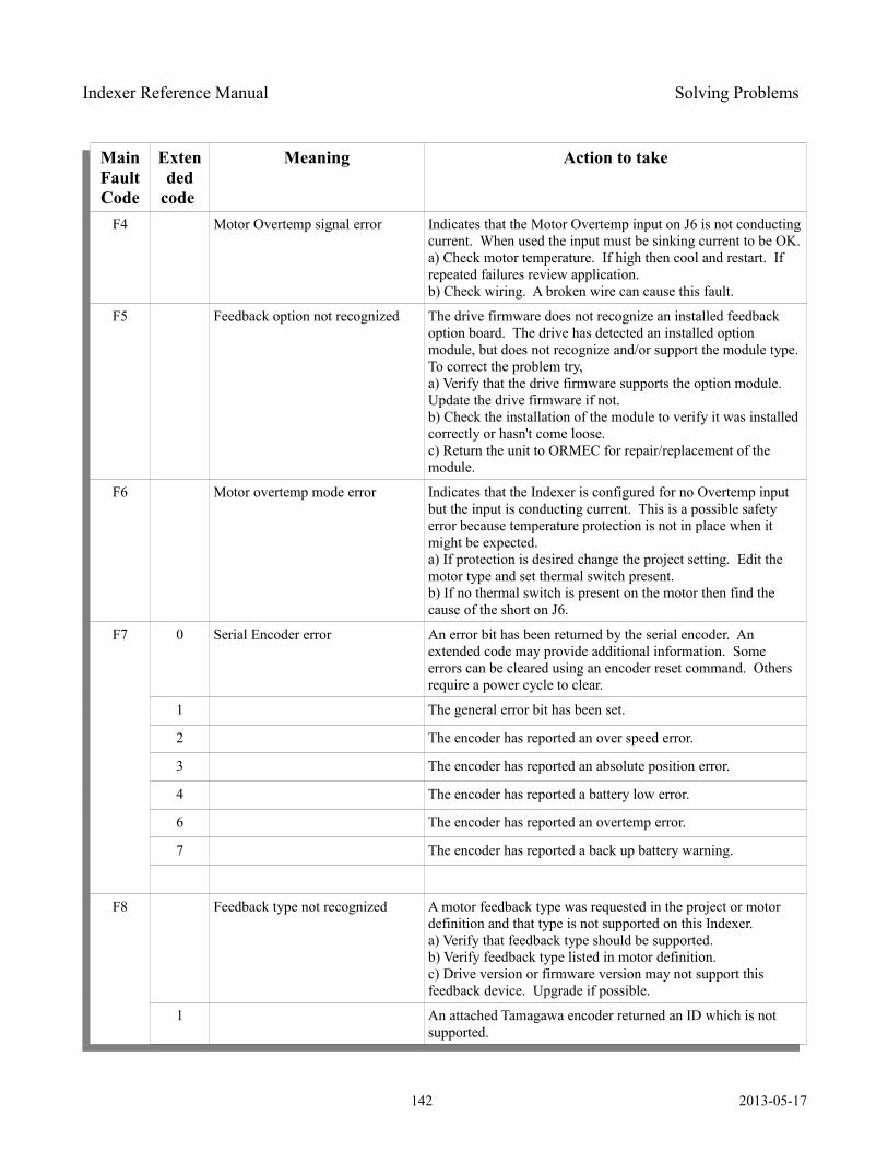
Indexer Reference Manual Solving Problems
Main Fault Code
Extended
code
Meaning Action to take
F4 Motor Overtemp signal error Indicates that the Motor Overtemp input on J6 is not conducting current. When used the input must be sinking current to be OK.a) Check motor temperature. If high then cool and restart. If repeated failures review application.b) Check wiring. A broken wire can cause this fault.
F5 Feedback option not recognized The drive firmware does not recognize an installed feedback option board. The drive has detected an installed option module, but does not recognize and/or support the module type. To correct the problem try,a) Verify that the drive firmware supports the option module. Update the drive firmware if not.b) Check the installation of the module to verify it was installed correctly or hasn't come loose.c) Return the unit to ORMEC for repair/replacement of the module.
F6 Motor overtemp mode error Indicates that the Indexer is configured for no Overtemp input but the input is conducting current. This is a possible safety error because temperature protection is not in place when it might be expected.a) If protection is desired change the project setting. Edit the motor type and set thermal switch present.b) If no thermal switch is present on the motor then find the cause of the short on J6.
F7 0 Serial Encoder error An error bit has been returned by the serial encoder. An extended code may provide additional information. Some errors can be cleared using an encoder reset command. Others require a power cycle to clear.
1 The general error bit has been set.
2 The encoder has reported an over speed error.
3 The encoder has reported an absolute position error.
4 The encoder has reported a battery low error.
6 The encoder has reported an overtemp error.
7 The encoder has reported a back up battery warning.
F8 Feedback type not recognized A motor feedback type was requested in the project or motor definition and that type is not supported on this Indexer.a) Verify that feedback type should be supported.b) Verify feedback type listed in motor definition.c) Drive version or firmware version may not support this feedback device. Upgrade if possible.
1 An attached Tamagawa encoder returned an ID which is not supported.
142 2013-05-17

Indexer Reference Manual Solving Problems
Main Fault Code
Extended
code
Meaning Action to take
2 The attached Sigma II encoder returned an ID which is not supported.
Table 33: Fault Codes
143 2013-05-17

Indexer Reference Manual Specifications
Specifications
Environmental Specifications
Operating Temperature 0 to 50°C
Maximum surrounding air temperature 50°C
Storage Temperature -20 to +70°C
Operating and Storage Humidity 10 to 90%, non-condensing
Table 34: Environmental Specifications
General Electrical Specifications for 200V Drives
Incoming main power line voltage – TB2 pins L1, L2, L3
Warning: Use the servomotor's voltage rating to determine the maximum input voltage for the servodrive. Connecting 230 VAC when using a 115 VAC motor will destroy the motor and may cause other injury.
XD203 and XD205(pins L1 and L2)
Single Phase, 50/60 Hz85 – 265 VAC115 or 230 VAC typical
XD210 - XD260pins L1, L2 and L3
Three Phase, 50/60 Hz85 – 265 VAC115 or 230 VAC typical
Control Power – AC input control power – TB2 pins r, t, FG
Vin SAC-XD2__-_ASingle Phase, 50/60 Hz85 – 265 VAC115 or 230 VAC typical1A maximum
Vout With AC control power 24VDC output availableTB1 pins 24V, 24R
24 V, +/- 7%1A maximum
Control Power – DC input control power – TB1 pins 24V, 24R, FG
144 2013-05-17
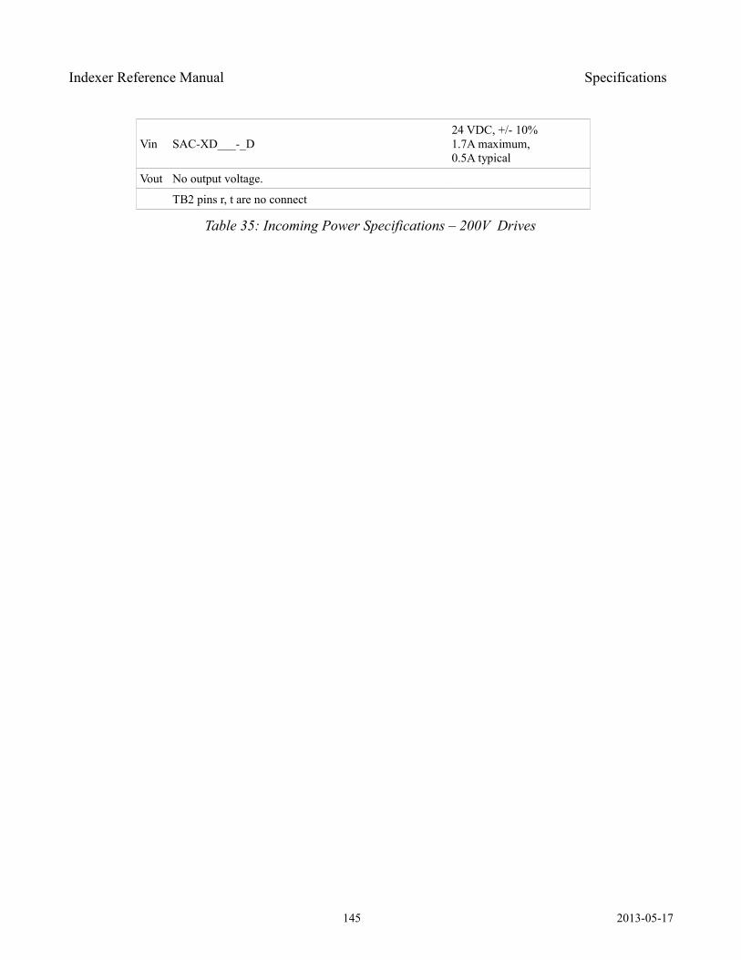
Indexer Reference Manual Specifications
Vin SAC-XD___-_D24 VDC, +/- 10%1.7A maximum,0.5A typical
Vout No output voltage.
TB2 pins r, t are no connect
Table 35: Incoming Power Specifications – 200V Drives
145 2013-05-17
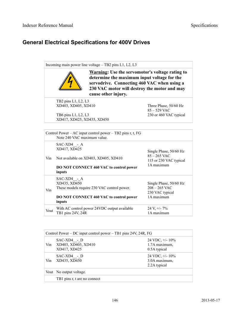
Indexer Reference Manual Specifications
General Electrical Specifications for 400V Drives
Incoming main power line voltage – TB2 pins L1, L2, L3
Warning: Use the servomotor's voltage rating to determine the maximum input voltage for the servodrive. Connecting 460 VAC when using a 230 VAC motor will destroy the motor and may cause other injury.
TB2 pins L1, L2, L3XD403, XD405, XD410
TB6 pins L1, L2, L3XD417, XD425, XD435, XD450
Three Phase, 50/60 Hz85 – 529 VAC230 or 460 VAC typical
Control Power – AC input control power – TB2 pins r, t, FG Note 240 VAC maximum value.
Vin
SAC-XD4__-_AXD417, XD425
Not available on XD403, XD405, XD410
DO NOT CONNECT 460 VAC to control power inputs
Single Phase, 50/60 Hz85 – 265 VAC115 or 230 VAC typical1A maximum
Vin
SAC-XD4__-_AXD435, XD450 These models require 230 VAC control power.
DO NOT CONNECT 460 VAC to control power inputs
Single Phase, 50/60 Hz208 – 265 VAC230 VAC typical1A maximum
Vout With AC control power 24VDC output availableTB1 pins 24V, 24R
24 V, +/- 7%1A maximum
Control Power – DC input control power – TB1 pins 24V, 24R, FG
VinSAC-XD4__-_DXD403, XD405, XD410 XD417, XD425
24 VDC, +/- 10%1.7A maximum,0.5A typical
VinSAC-XD4__-_DXD435, XD450
24 VDC, +/- 10%3.0A maximum,2.2A typical
Vout No output voltage.
TB1 pins r, t are no connect
146 2013-05-17
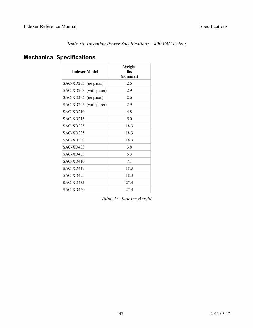
Indexer Reference Manual Specifications
Table 36: Incoming Power Specifications – 400 VAC Drives
Mechanical Specifications
Indexer ModelWeight
lbs(nominal)
SAC-XD203 (no pacer) 2.6
SAC-XD203 (with pacer) 2.9
SAC-XD205 (no pacer) 2.6
SAC-XD205 (with pacer) 2.9
SAC-XD210 4.8
SAC-XD215 5.0
SAC-XD225 18.3
SAC-XD235 18.3
SAC-XD260 18.3
SAC-XD403 3.8
SAC-XD405 5.3
SAC-XD410 7.1
SAC-XD417 18.3
SAC-XD425 18.3
SAC-XD435 27.4
SAC-XD450 27.4
Table 37: Indexer Weight
147 2013-05-17
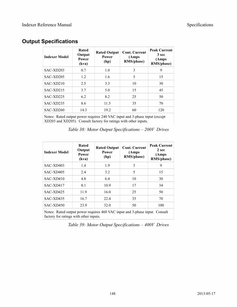
Indexer Reference Manual Specifications
Output Specifications
Indexer Model
Rated Output Power(kva)
Rated Output Power(hp)
Cont. Current(Amps
RMS/phase)
Peak Current3 sec
(Amps RMS/phase)
SAC-XD203 0.7 1.0 3 9
SAC-XD205 1.2 1.6 5 15
SAC-XD210 2.5 3.3 10 30
SAC-XD215 3.7 5.0 15 45
SAC-XD225 6.2 8.2 25 50
SAC-XD235 8.6 11.5 35 70
SAC-XD260 14.3 19.2 60 120
Notes: Rated output power requires 240 VAC input and 3-phase input (except XD203 and XD205). Consult factory for ratings with other inputs.
Table 38: Motor Output Specifications – 200V Drives
Indexer Model
Rated Output Power(kva)
Rated Output Power(hp)
Cont. Current(Amps
RMS/phase)
Peak Current2 sec
(Amps RMS/phase)
SAC-XD403 1.4 1.9 3 9
SAC-XD405 2.4 3.2 5 15
SAC-XD410 4.8 6.4 10 30
SAC-XD417 8.1 10.9 17 34
SAC-XD425 11.9 16.0 25 50
SAC-XD435 16.7 22.4 35 70
SAC-XD450 23.9 32.0 50 100
Notes: Rated output power requires 460 VAC input and 3-phase input. Consult factory for ratings with other inputs.
Table 39: Motor Output Specifications – 400V Drives
148 2013-05-17
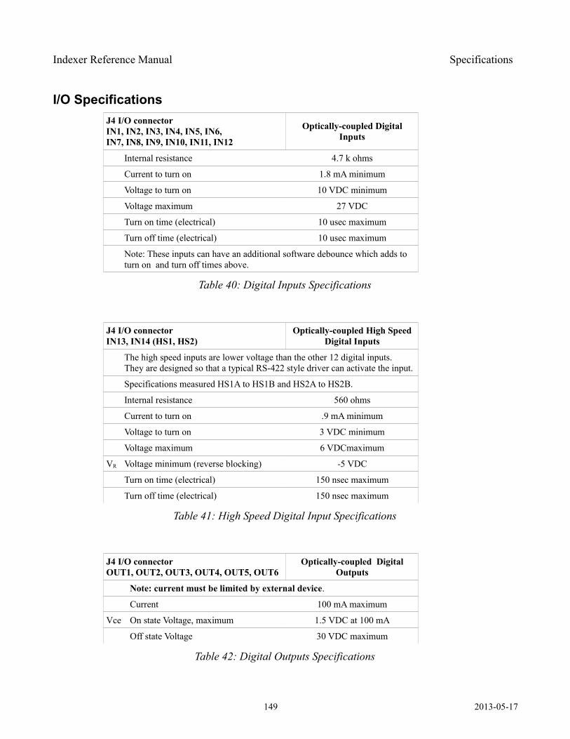
Indexer Reference Manual Specifications
I/O Specifications J4 I/O connector IN1, IN2, IN3, IN4, IN5, IN6, IN7, IN8, IN9, IN10, IN11, IN12
Optically-coupled Digital Inputs
Internal resistance 4.7 k ohms
Current to turn on 1.8 mA minimum
Voltage to turn on 10 VDC minimum
Voltage maximum 27 VDC
Turn on time (electrical) 10 usec maximum
Turn off time (electrical) 10 usec maximum
Note: These inputs can have an additional software debounce which adds to turn on and turn off times above.
Table 40: Digital Inputs Specifications
J4 I/O connector IN13, IN14 (HS1, HS2)
Optically-coupled High Speed Digital Inputs
The high speed inputs are lower voltage than the other 12 digital inputs. They are designed so that a typical RS-422 style driver can activate the input.
Specifications measured HS1A to HS1B and HS2A to HS2B.
Internal resistance 560 ohms
Current to turn on .9 mA minimum
Voltage to turn on 3 VDC minimum
Voltage maximum 6 VDCmaximum
VR Voltage minimum (reverse blocking) -5 VDC
Turn on time (electrical) 150 nsec maximum
Turn off time (electrical) 150 nsec maximum
Table 41: High Speed Digital Input Specifications
J4 I/O connector OUT1, OUT2, OUT3, OUT4, OUT5, OUT6
Optically-coupled Digital Outputs
Note: current must be limited by external device.
Current 100 mA maximum
Vce On state Voltage, maximum 1.5 VDC at 100 mA
Off state Voltage 30 VDC maximum
Table 42: Digital Outputs Specifications
149 2013-05-17
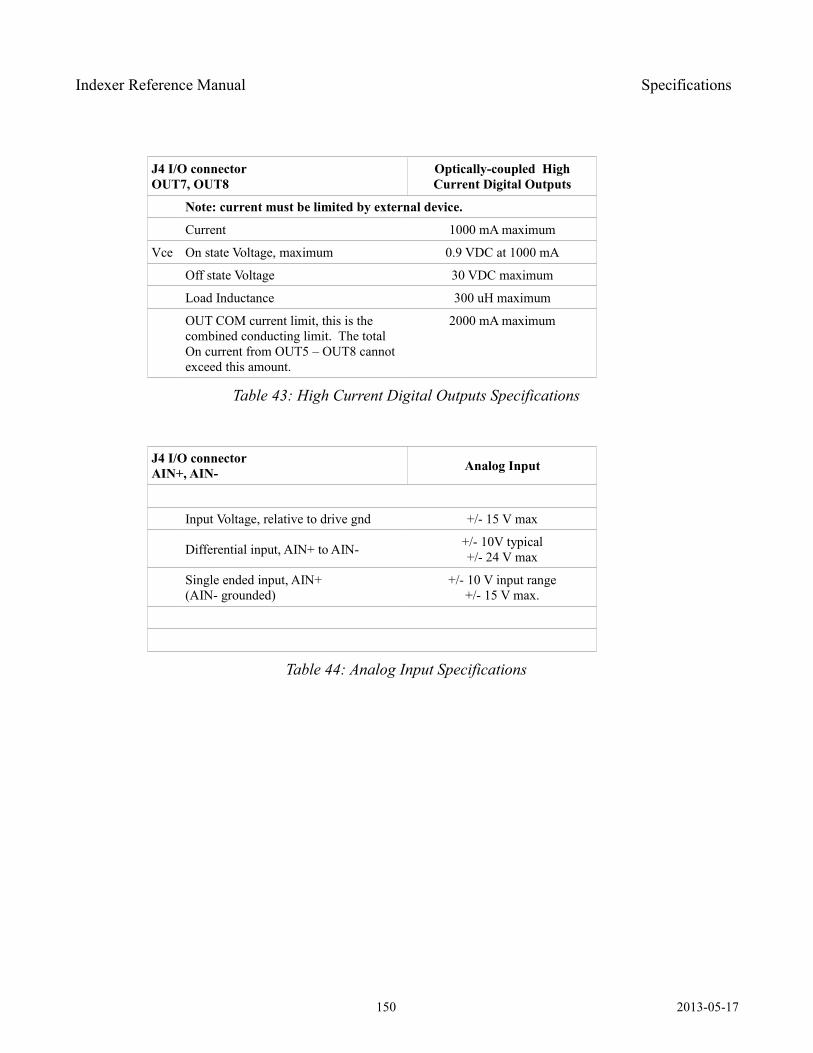
Indexer Reference Manual Specifications
J4 I/O connector OUT7, OUT8
Optically-coupled High Current Digital Outputs
Note: current must be limited by external device.
Current 1000 mA maximum
Vce On state Voltage, maximum 0.9 VDC at 1000 mA
Off state Voltage 30 VDC maximum
Load Inductance 300 uH maximum
OUT COM current limit, this is the combined conducting limit. The total On current from OUT5 – OUT8 cannot exceed this amount.
2000 mA maximum
Table 43: High Current Digital Outputs Specifications
J4 I/O connector AIN+, AIN- Analog Input
Input Voltage, relative to drive gnd +/- 15 V max
Differential input, AIN+ to AIN- +/- 10V typical+/- 24 V max
Single ended input, AIN+(AIN- grounded)
+/- 10 V input range+/- 15 V max.
Table 44: Analog Input Specifications
150 2013-05-17
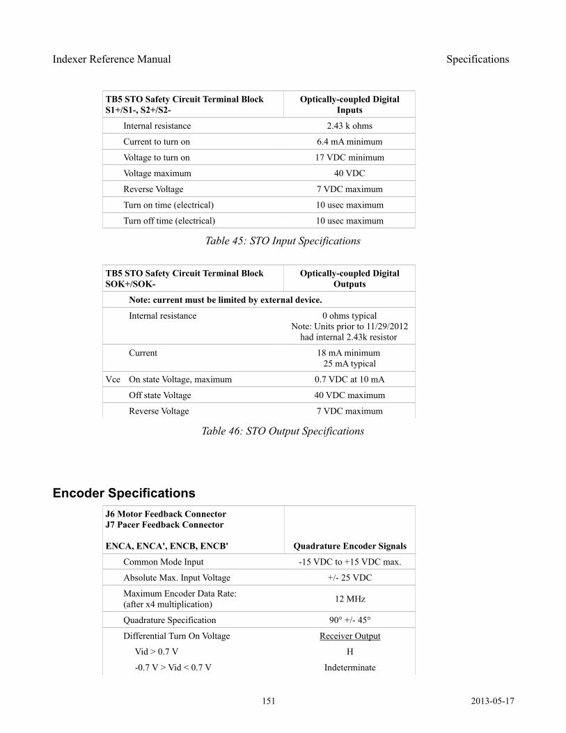
Indexer Reference Manual Specifications
TB5 STO Safety Circuit Terminal Block S1+/S1-, S2+/S2-
Optically-coupled Digital Inputs
Internal resistance 2.43 k ohms
Current to turn on 6.4 mA minimum
Voltage to turn on 17 VDC minimum
Voltage maximum 40 VDC
Reverse Voltage 7 VDC maximum
Turn on time (electrical) 10 usec maximum
Turn off time (electrical) 10 usec maximum
Table 45: STO Input Specifications
TB5 STO Safety Circuit Terminal Block SOK+/SOK-
Optically-coupled Digital Outputs
Note: current must be limited by external device.
Internal resistance 0 ohms typicalNote: Units prior to 11/29/2012
had internal 2.43k resistor
Current 18 mA minimum 25 mA typical
Vce On state Voltage, maximum 0.7 VDC at 10 mA
Off state Voltage 40 VDC maximum
Reverse Voltage 7 VDC maximum
Table 46: STO Output Specifications
Encoder Specifications J6 Motor Feedback ConnectorJ7 Pacer Feedback Connector
ENCA, ENCA', ENCB, ENCB' Quadrature Encoder Signals
Common Mode Input -15 VDC to +15 VDC max.
Absolute Max. Input Voltage +/- 25 VDC
Maximum Encoder Data Rate:(after x4 multiplication) 12 MHz
Quadrature Specification 90° +/- 45°
Differential Turn On Voltage Receiver Output
Vid > 0.7 V H
-0.7 V > Vid < 0.7 V Indeterminate
151 2013-05-17
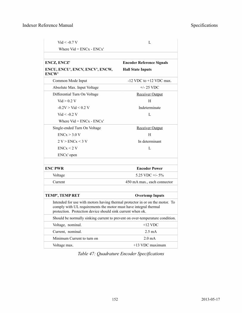
Indexer Reference Manual Specifications
Vid < -0.7 V L
Where Vid = ENCx - ENCx'
ENCZ, ENCZ' Encoder Reference Signals
ENCU, ENCU', ENCV, ENCV', ENCW, ENCW'
Hall State Inputs
Common Mode Input -12 VDC to +12 VDC max.
Absolute Max. Input Voltage +/- 25 VDC
Differential Turn On Voltage Receiver Output
Vid > 0.2 V H
-0.2V > Vid < 0.2 V Indeterminate
Vid < -0.2 V L
Where Vid = ENCx - ENCx'
Single-ended Turn On Voltage Receiver Output
ENCx > 3.0 V H
2 V > ENCx < 3 V In determinant
ENCx < 2 V L
ENCx' open
ENC PWR Encoder Power
Voltage 5.25 VDC +/- 5%
Current 450 mA max., each connector
TEMP', TEMP RET Overtemp Inputs
Intended for use with motors having thermal protector in or on the motor. To comply with UL requirements the motor must have integral thermal protection. Protection device should sink current when ok.
Should be normally sinking current to prevent on over-temperature condition.
Voltage, nominal. +12 VDC
Current, nominal. 2.5 mA
Minimum Current to turn on 2.0 mA
Voltage max. +13 VDC maximum
Table 47: Quadrature Encoder Specifications
152 2013-05-17
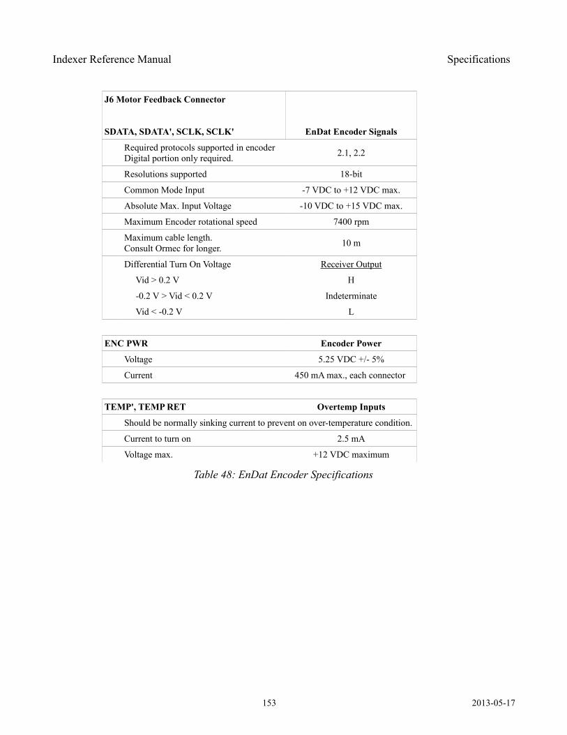
Indexer Reference Manual Specifications
J6 Motor Feedback Connector
SDATA, SDATA', SCLK, SCLK' EnDat Encoder Signals
Required protocols supported in encoderDigital portion only required. 2.1, 2.2
Resolutions supported 18-bit
Common Mode Input -7 VDC to +12 VDC max.
Absolute Max. Input Voltage -10 VDC to +15 VDC max.
Maximum Encoder rotational speed 7400 rpm
Maximum cable length. Consult Ormec for longer. 10 m
Differential Turn On Voltage Receiver Output
Vid > 0.2 V H
-0.2 V > Vid < 0.2 V Indeterminate
Vid < -0.2 V L
ENC PWR Encoder Power
Voltage 5.25 VDC +/- 5%
Current 450 mA max., each connector
TEMP', TEMP RET Overtemp Inputs
Should be normally sinking current to prevent on over-temperature condition.
Current to turn on 2.5 mA
Voltage max. +12 VDC maximum
Table 48: EnDat Encoder Specifications
153 2013-05-17
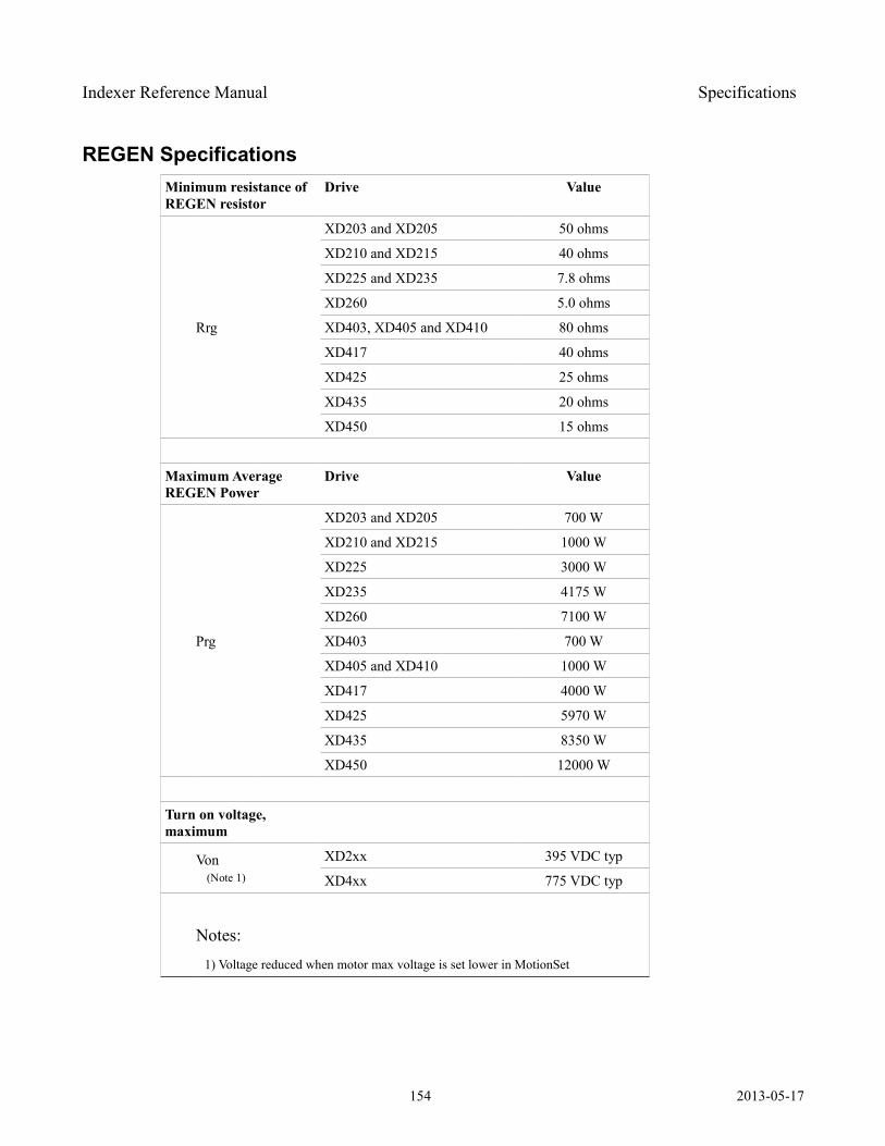
Indexer Reference Manual Specifications
REGEN Specifications Minimum resistance of REGEN resistor
Drive Value
Rrg
XD203 and XD205 50 ohms
XD210 and XD215 40 ohms
XD225 and XD235 7.8 ohms
XD260 5.0 ohms
XD403, XD405 and XD410 80 ohms
XD417 40 ohms
XD425 25 ohms
XD435 20 ohms
XD450 15 ohms
Maximum Average REGEN Power
Drive Value
Prg
XD203 and XD205 700 W
XD210 and XD215 1000 W
XD225 3000 W
XD235 4175 W
XD260 7100 W
XD403 700 W
XD405 and XD410 1000 W
XD417 4000 W
XD425 5970 W
XD435 8350 W
XD450 12000 W
Turn on voltage, maximum
Von (Note 1)
XD2xx 395 VDC typ
XD4xx 775 VDC typ
Notes: 1) Voltage reduced when motor max voltage is set lower in MotionSet
154 2013-05-17
Indexer Reference Manual Index
Index
Alphabetical Index A Application Units.......................13, 96, 101, 105, 110B Brake...................................................................
Electronic.........................................................Electronic Brake....................................96, 108
C Communication.....................................................
Ethernet 13, 19, 22-24, 26, 27, 61, 117, 120, 128-132, 134 Fieldbus................................91, 94, 103, 128-131 Modbus TCP......................................14, 22, 117 USB.................13, 19, 22-24, 26, 27, 117, 120, 128
Connectors............................................................ Connector.........................................................
J1 - Ethernet...........................................24, 26J2 - USB................................................24, 26J3 - Fieldbus..................................79, 128, 130J4 - I/O...................34-36, 47, 48, 50, 51, 55, 102J6 - Feedback. . .24, 26, 34-36, 44-46, 66, 102, 106, 110, 141, 142J7 - Aux..............34-36, 86, 97, 98, 102, 106, 141
Terminal Blocks.................................................TB1 - DC...................20, 24, 26, 34-39, 102, 134TB2 - AC input...........20, 24, 26, 34-40, 102, 134TB3 - Regen............................34, 102, 112, 137TB4 - Motor..........24, 26, 34, 35, 41, 42, 102, 137TB6 - Motor.....................20, 36, 39, 41, 43, 102
Control power...............................23, 27, 37-39, 134E Enable.....25, 29, 46, 57, 67, 92, 95, 101, 103, 104, 130, 134, 137-139 Enable..................................................................
Software enable..............................................47 Encoder................................................................
Absolute encoder.........................57, 110, 111, 138
Lineshaft...........................................................Pacer/Aux14, 22, 24, 27, 31, 57, 58, 62, 86, 87, 96-101, 120, 140, 141
EnDat..........................................................45, 46 Error......................56, 58, 61, 123, 132, 133, 136-142F Fault.....14, 56-58, 61, 67, 112, 123, 132, 135-137, 139, 140, 142, 143 Feedback..............................................................
Endat................................................45, 46, 104 Quadrature. . .14, 43, 44, 62, 94, 96-98, 100, 101, 141 Serial................................14, 44-46, 94, 141, 142 Yaskawa..........................14, 44, 45, 110, 111, 141
I I/O exerciser...................25, 28, 29, 47, 120, 122, 134 Indicator...................................................9, 94, 95 Inputs.14, 20, 25, 29, 39, 47, 48, 50, 56, 92, 93, 98, 122, 123, 134, 139L Limits..................................................................
Hardware travel........................................58, 109 Programmable Limit Switch.....57, 96, 105-108, 123, 130 Software travel.......................................109, 136 System Limits...............................................109
M Models.................................................................
XD203......30, 31, 37, 39-42, 102, 111, 112, 115, 136 XD205........................................25, 31, 102, 115 XD210........................................22, 25, 102, 115 XD215...........30, 37, 40-42, 102, 111, 112, 115, 136 XD225.........................30, 32, 38, 41, 43, 102, 115 XD235.............................................32, 102, 115 XD260....................30, 32, 38, 39, 41, 43, 102, 115 XD403..................................39-42, 102, 112, 115 XD405.............................................30, 102, 115
155 2013-05-17
Indexer Reference Manual Index
XD410.............................30, 40-42, 102, 112, 115 XD417.........................30, 32, 38, 41, 43, 102, 115 XD425........................................32, 38, 102, 115 XD435........................................32, 38, 102, 115 XD450.........................30, 32, 38, 41, 43, 102, 115
Modulo......................................75, 77, 96, 106-108 Motion.................................................................
Gear In.....................................................86, 91 Gear Relative........................................86, 88-90 Home.22, 25, 29, 56, 58, 66, 67, 70, 75, 77, 110, 111, 124, 140 Modulo..................................75, 77, 96, 106-108 Motion Table.25, 56, 57, 70, 81, 84, 90, 91, 103, 136, 140 Move Absolute..........................................75, 77 Move relative...................................70, 72-74, 81 Move Velocity.................................78, 79, 81, 84 Repeat Motion...........................................81, 84
MotionSet. 2, 9, 13, 15, 16, 18, 19, 23-26, 46, 47, 56-58, 60, 62, 64, 86, 94-96, 100-103, 105, 108-110, 117, 119, 123-125, 128-130, 134, 137, 139, 140 Motor feedback 14, 26, 43-46, 66, 87, 94, 100, 101, 141, 142 Motor power..........20, 26, 27, 39-43, 94, 104, 137, 138 Mount............................10, 20, 30, 46, 136, 138, 141O Outputs.................................14, 52-55, 57, 122, 137P Project Storage.................................................102Q
Quadrature.......14, 43, 44, 62, 94, 96-98, 100, 101, 141R Regen Resistor.......................................................
Regen:.........................................................111S Serial....................................14, 44-46, 94, 141, 142 Software....2, 9, 24, 26, 57, 58, 100, 109, 129, 130, 136, 139, 140 Specifications......................................132, 136, 144T Terminal Blocks.....................................................
Connector.........................................................J1 - Ethernet...........................................24, 26J2 - USB................................................24, 26J3 - Fieldbus..................................79, 128, 130J4 - I/O...................34-36, 47, 48, 50, 51, 55, 102J6 - Feedback. . .24, 26, 34-36, 44-46, 66, 102, 106, 110, 141, 142J7 - Aux..............34-36, 86, 97, 98, 102, 106, 141
Terminal Blocks.................................................TB1 - DC...................20, 24, 26, 34-39, 102, 134TB2 - AC input...........20, 24, 26, 34-40, 102, 134TB3 - Regen............................34, 102, 112, 137TB4 - Motor..........24, 26, 34, 35, 41, 42, 102, 137TB6 - Motor.....................20, 36, 39, 41, 43, 102
Tuning...........................19, 62, 64, 65, 109, 124, 140U User Units................................13, 96, 101, 105, 110Y Yaskawa..............................14, 44, 45, 110, 111, 141
156 2013-05-17
Recommended