
Implementation of Safety and Security System for
House Boats using PIC Microcontroller
Indulal B ME student in Instrumentation & Control,
Panjab University,
Chandigarh
Shimi S. L Assistant Professor
Department of Electrical Engineering,
National Institute of Technical Teachers’
Training and Research, Chandigarh
Abstract— The paper illustrates the implementation of a
complete Smart safety system for house boats using PIC
Microcontroller, ZigBee Pro and LabVIEW. The system
incorporates relevant sensors and actuators for the
measurement and monitoring of critical parameters that
adversely affect the safety of house boats as well as security of
tourists. A PC based control station, whose Graphical User
Interface is designed using Lab VIEW, is used to monitor
remotely the respective house boat. Also the location of the
house boat is made available in the remote station as well as in
the house boat by GPS navigational system.
Keywords— House boats, PIC, ZigBee, LabVIEW, GPS
I. INTRODUCTION
‘God’s Own Country’, Kerala, has immense scope in
tourism, especially ecotourism. One of the innovative and
appealing aspects of ecotourism in Kerala is its house boats.
The industry was thriving at a profitable level, but of late,
frequent accidents that happened in house boats poised a
serious challenge to this sector of tourism. Accidents, major
and minor, occur in house boat due to inadequate safety
measures incorporated in house boats. Also the associated
malpractices contributed a major share to the causes of
accidents.
Nowadays, along with fast development in electronics as
well as wireless communication technology, the foresaid
problem can be solved to a large extend. Moreover the sensor
development technology for measuring various parameters
that cause accidents in house boat, has reached at its peak. The
main causes of accidents in house boats are due to overload,
fire, alcohol drunken driver as well as passengers, obstacles,
over speed, inclination, out dated house boats, short circuits,
engine coolant level etc.
An automatic system designed using PIC Micro controller
with relevant sensors and actuators can meet the requirements
of an effective and efficient monitoring system for house
boats. Global Position System (GPS) based fleet tracking unit
is used to identify the location of a houseboat and transmit the
spatial or geographic information to a remote control station
over the wireless communication network. The GPS system
will also help the effective navigation of the houseboat. A
remote station is developed for monitoring and controlling
various relevant parameters which cause the problems towards
the safety of house boats as well as security of the tourists. If
any abnormal conditions occur, the automatic system
produces warning along with audible and visual alarms and
send the details to the control station through the ZigBee
communication network. From the Human Machine Interface
(HMI) device, of which GUI is designed using LabVIEW,
arranged in the control room, the houseboat can be guided.
Moreover any alerts from the weather forecasting center can
be communicated to respective house boats.
TABLE (1) Parameters and Corresponding Actions Sl.No. Parameter Expected Actions
1 Fire Indication, Alarm, Transmission
,Control@
2 Overload Indication, Alarm, Transmission,
Control#
3 Alcohol (Driver) Indication, Alarm, Transmission,
Control*
4 Alcohol(Passenger) Indication, Alarm, Transmission, Control^
5 Free board gap Indication, Alarm, Transmission
6 Obstacles Indication, Alarm, Transmission
7 Speed Indication, Alarm, Transmission
8 Inclination Indication, Alarm, Transmission
9 Gas leakage Indication, Alarm, Transmission
@ Automatic cut of main supply, emergency standby supply
in line, Auto start of fire extinguisher (actions depends on the
intensity of fire)
#Engine cannot be started.
* Engine cannot be started
^Entry of tourists to the upper deck is blocked.
A. Related Work
A waypoint tracking guidance controller [1] for an
autonomous house boat, based on fuzzy controller has been
developed with digital compass and a differentially connected
GPS receiver for getting the navigation data. The general
concept of automatic berthing system [2] for ships was
developed through GPS based system which provides the data
for position, velocity, altitudes, angular velocity and time. A
control system model [3] for the analysis was discussed for a
fully autonomous sail boat navigational system. The proposed
system allows an expert system to develop good routs and
exploring environmental conditions such as winds, tides and
currents. An auto pilot system [4] was designed and
developed for guiding the trajectory of a small boat as it
perform berthing. A commanding system [5] based on client
and server structure was designed, for working boats’
International Journal of Engineering Research & Technology (IJERT)
ISSN: 2278-0181
www.ijert.orgIJERTV4IS110235
(This work is licensed under a Creative Commons Attribution 4.0 International License.)
Vol. 4 Issue 11, November-2015
137
operation. It combines the application of GPS and GIS
technology.
A system [6] was proposed for obstacle detection of an
intelligent vehicle based on Lab VIEW and laser measurement
principle. The obstacles are remotely measured by Laser
Measurement System (LMS 291) and the measurement data
are collected and processed in LabVIEW environment by
serial port RS-232 through VISA. A methodology [7] was
proposed to construct a wire-less fire alarm system based on
ZigBee. In this paper a comparative study of various wireless
technologies like Wi-Fi, ZigBee and Bluetooth was also
given. The system based on ZigBee overcomes the limitations
of the cable alarm system and avoids high power consumption
of the wireless communications technology. Compared with
existing wireless sensor network, it has some advantages such
as low cost, high network capacity, long life etc. A GPRS
based positioning system [8] was presented with an accurate
localization has been implemented using PIC18F4550
Microchip. The combination of the GPS and GPRS provides
continuous and real time tracking. The system also provides
information regarding the vehicle status such as speed,
mileage, and driver performance.
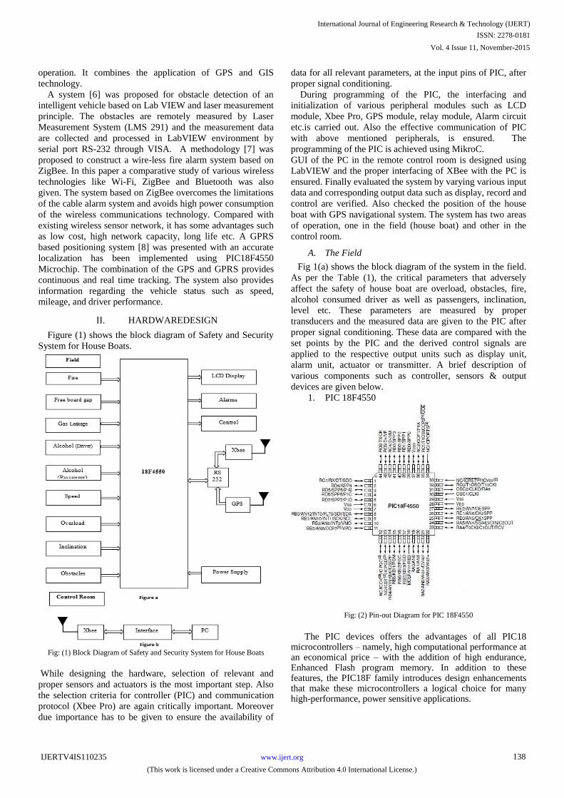
II. HARDWAREDESIGN
Figure (1) shows the block diagram of Safety and Security
System for House Boats.
Fig: (1) Block Diagram of Safety and Security System for House Boats
While designing the hardware, selection of relevant and
proper sensors and actuators is the most important step. Also
the selection criteria for controller (PIC) and communication
protocol (Xbee Pro) are again critically important. Moreover
due importance has to be given to ensure the availability of
data for all relevant parameters, at the input pins of PIC, after
proper signal conditioning.
During programming of the PIC, the interfacing and
initialization of various peripheral modules such as LCD
module, Xbee Pro, GPS module, relay module, Alarm circuit
etc.is carried out. Also the effective communication of PIC
with above mentioned peripherals, is ensured. The
programming of the PIC is achieved using MikroC.
GUI of the PC in the remote control room is designed using
LabVIEW and the proper interfacing of XBee with the PC is
ensured. Finally evaluated the system by varying various input
data and corresponding output data such as display, record and
control are verified. Also checked the position of the house
boat with GPS navigational system. The system has two areas
of operation, one in the field (house boat) and other in the
control room.
A. The Field
Fig 1(a) shows the block diagram of the system in the field.
As per the Table (1), the critical parameters that adversely
affect the safety of house boat are overload, obstacles, fire,
alcohol consumed driver as well as passengers, inclination,
level etc. These parameters are measured by proper
transducers and the measured data are given to the PIC after
proper signal conditioning. These data are compared with the
set points by the PIC and the derived control signals are
applied to the respective output units such as display unit,
alarm unit, actuator or transmitter. A brief description of
various components such as controller, sensors & output
devices are given below.
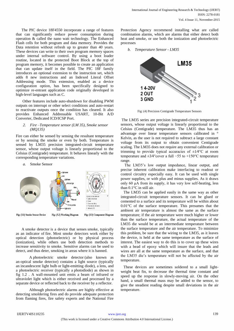
1. PIC 18F4550
Fig: (2) Pin-out Diagram for PIC 18F4550
The PIC devices offers the advantages of all PIC18 microcontrollers – namely, high computational performance at an economical price – with the addition of high endurance, Enhanced Flash program memory. In addition to these features, the PIC18F family introduces design enhancements that make these microcontrollers a logical choice for many high-performance, power sensitive applications.
International Journal of Engineering Research & Technology (IJERT)
ISSN: 2278-0181
www.ijert.orgIJERTV4IS110235
(This work is licensed under a Creative Commons Attribution 4.0 International License.)
Vol. 4 Issue 11, November-2015
138
The PIC device 18F4550 incorporate a range of features that can significantly reduce power consumption during operation & called the nano watt technology. The Enhanced Flash cells for both program and data memory. Provides the Data retention without refresh up to greater than 40 years. These devices can write to their own program memory spaces under internal software control. By using a boot loader routine, located in the protected Boot Block at the top of program memory, it becomes possible to create an application that can update itself in the field. The PIC 18F family introduces an optional extension to the instruction set, which adds 8 new instructions and an Indexed Literal Offset Addressing mode. This extension, enabled as a device configuration option, has been specifically designed to optimize re-entrant application code originally developed in high-level languages such as C.
Other features include auto-shutdown for disabling PWM outputs on interrupt or other select conditions and auto-restart to reactivate outputs once the condition has cleared. It also provides Enhanced Addressable USART, 10-Bit A/D Converter, Dedicated ICD/ICSP Port.
2. Fire –Temperature sensor (LM 35), Smoke sensor (MQ135)
Fire can either be sensed by sensing the resultant temperature or by sensing the smoke or even by both. Temperature is sensed by LM35 precision integrated-circuit temperature sensor, whose output voltage is linearly proportional to the Celsius (Centigrade) temperature. It behaves linearly with the corresponding temperature variations.
a. Smoke Sensor
A smoke detector is a device that senses smoke, typically as an indicator of fire. Most smoke detectors work either by optical detection (photoelectric) or by physical process (ionization), while others use both detection methods to increase sensitivity to smoke. Sensitive alarms can be used to detect, and thus deter, smoking in areas where it is banned.
A photoelectric smoke detector (also known as an optical smoke detector) contains a light source (typically an incandescent light bulb or light-emitting diode), a lens, and a photoelectric receiver (typically a photodiode) as shown in fig 1.2 . A wall-mounted unit emits a beam of infrared or ultraviolet light which is either received and processed by a separate device or reflected back to the receiver by a reflector.
Although photoelectric alarms are highly effective at detecting smoldering fires and do provide adequate protection from flaming fires, fire safety experts and the National Fire
Protection Agency recommend installing what are called combination alarms, which are alarms that either detect both heat and smoke, or use both the ionization and photoelectric processes
b. Temperature Sensor - LM35
Fig: (4) Precision Centigrade Temperature Sensors
The LM35 series are precision integrated-circuit temperature
sensors, whose output voltage is linearly proportional to the
Celsius (Centigrade) temperature. The LM35 thus has an
advantage over linear temperature sensors calibrated in °
Kelvin, as the user is not required to subtract a large constant
voltage from its output to obtain convenient Centigrade
scaling. The LM35 does not require any external calibration or
trimming to provide typical accuracies of ±1⁄4°C at room
temperature and ±3⁄4°cover a full −55 to +150°C temperature
range.
The LM35’s low output impedance, linear output, and
precise inherent calibration make interfacing to readout or
control circuitry especially easy. It can be used with single
power supplies, or with plus and minus supplies. As it draws
only 60 μA from its supply, it has very low self-heating, less
than 0.1°C in still air.
The LM35 can be applied easily in the same way as other
integrated-circuit temperature sensors. It can be glued or
cemented to a surface and its temperature will be within about
0.01°C of the surface temperature. This presumes that the
ambient air temperature is almost the same as the surface
temperature; if the air temperature were much higher or lower
than the surface temperature, the actual temperature of the
LM35 die would be at an intermediate temperature between
the surface temperature and the air temperature. To minimize
this problem, be sure that the wiring to the LM35, as it leaves
the device, is held at the same temperature as the surface of
interest. The easiest way to do this is to cover up these wires
with a bead of epoxy which will insure that the leads and
wires are all at the same temperature as the surface, and that
the LM35 die’s temperature will not be affected by the air
temperature.
These devices are sometimes soldered to a small light-
weight heat fin, to decrease the thermal time constant and
speed up the response in slowly-moving air. On the other
hand, a small thermal mass may be added to the sensor, to
give the steadiest reading despite small deviations in the air
temperature.
International Journal of Engineering Research & Technology (IJERT)
ISSN: 2278-0181
www.ijert.orgIJERTV4IS110235
(This work is licensed under a Creative Commons Attribution 4.0 International License.)
Vol. 4 Issue 11, November-2015
139

3. Overload-Strain gauge with load cell
When a force is exerted on an object, the length of the
object will change. The ratio of the change in length to the
original length is called strain. A strain gauge is a small
section of very fine wire that changes electrical resistance
when its dimensions are changed by weight or subjected to a
strain. This can be used to measure the weight of persons
entering the houseboat. Here we are placing a platform at the
entrance of house boat. This platform is built with a strain
gauge to measure the weights of persons entering into the
houseboat. It will add the weight of each person when entering
the boat and subtracts when they leave the houseboat. An IR
based counting mechanism is integrated along with this
system to count the entering and leaving of persons. The
output from this system represents the mean weight of the
persons entered into the houseboat. If the value exceeds a
particular limit then the controller will produce a buzzer alert
and the ignition control to the engine is closed by using a relay
control element.
4. Obstacle-Laser Based Method
Fig: (6) LASER Based Obstacle Detector
A time-of-flight laser sensor operates by emitting a
concentrated laser energy pulse. The pulse travels away from
the sensor, strikes a surface, and returns. A clock measures
the time elapsed between the beginning of the pulse and the
leading edge of the return pulse from the receiver. For under
water obstacles, Sonar can be used where the ordinary Laser
is not effective.
5. Gas (LPG) -MQ135
Fig: (7) MQ 135
A gas detector is a device that detects the presence of gases
in an area, often as part of a safety system. This type of
equipment is used to detect a gas leak and interface with a
control system so a process can be automatically shut down.
A gas detector can sound an alarm to operators in the area
where the leak is occurring, giving them the opportunity to
leave. This type of device is important because there are
many gases that can be harmful to organic life, such as
humans or animals. The MQ series of gas sensors use a small
heater inside with an electro-chemical sensor. They are
sensitive for a range of gases and are used indoors at room
temperature. MQ-135 performs a good detection to smoke
and other harmful gas, especially sensitive to ammonia,
sulfide and benzene steam. The conductivity of the gas sensor
raises along with the concentration of the polluting gas
increases. They are used in air quality control equipment’s &
safety devices for buildings/offices, are suitable for detecting
of NH3,NOx, alcohol, Benzene, smoke,CO2 ,etc.
6. Alcohol - MQ3
Fig: (8) MQ-3 Alcohol Detector
When the alcohol molecules in the air meet the heated
electrode, the ethanol burns into acetic acid and more current
is produced. Sensitive material of MQ-3 gas sensor is SnO2,
which with lower conductivity in clean air. When the target
alcohol gas exist, the sensor’s conductivity is higher along
with the gas concentration rising.
International Journal of Engineering Research & Technology (IJERT)
ISSN: 2278-0181
www.ijert.orgIJERTV4IS110235
(This work is licensed under a Creative Commons Attribution 4.0 International License.)
Vol. 4 Issue 11, November-2015
140

7. Free-board gap (Level)-Float & Potentiometer
Fig: (9) Float & Pot Method
Free board gap is the level difference between the body
surface and water surface. This is measured by an
arrangement of Float and potentiometer assembly, simply
called pot & float method which is set up on either side of the
house boat as shown in figure (9) when the level changes, the
float, attached to the moving contact of the potentiometer,
moves and the output voltage changes. Taking the average of
the voltages of the potentiometers on either side of the boat,
the free board gap is obtained. Usually on site calibrations are
done for measuring the free board gap as the body surface
and water surface ratio of each boats vary as variations in its
size, design features and even the water flow.
8. Inclination- Float & Potentiometer
The arrangement for measuring the free board gap can also
be used for measuring the inclination of house boat. Taking
the difference between the voltages of the potentiometers on
either side of the boat, the free inclination of the boat is
obtained.
9. Speed – Positive Displacement Flow Meter
The engine speed can be measured by Tachogenerator.
However the actual speed of the boat is not the same as the
engine speed since it is mostly depends on the nature of water
such as its density, direction of water flow, other small
obstacles etc. Hence actual speed can be measured by any
positive displacement type flow meter.
10. Short Circuit Protection- Relay Module
Short circuit resulted from fire is avoided by energizing the
relay with the signal from the fire sensor.
A relay is an electrically operated switch... Relays are used
where it is necessary to control a circuit by a low-power
signal (with complete electrical isolation between control and
controlled circuits), or where several circuits must be
controlled by one signal. A relay can handle the high power
required to directly control an electric motor or other loads is
called a contactor. Relays with calibrated operating
characteristics and sometimes multiple operating coils are
used to protect electrical circuits from overload or faults; in
modern electric power systems these functions are performed
by digital instruments still called "protective relays". A
simple electromagnetic relay consists of a coil of wire
wrapped around a soft iron core, an iron yoke which provides
a low reluctance path for magnetic flux, a movable iron
armature, and one or more sets of contacts. The armature is
hinged to the yoke and mechanically linked to one or more
sets of moving contacts. It is held in place by a spring so that
when the relay is de-energized there is an air gap in the
magnetic circuit. In this condition, one of the two sets of
contacts in the relay pictured is closed, and the other set is
open. Other relays may have more or fewer sets of contacts
depending on their function.
11. Alcohol (Passenger) – Solenoid
Entry of drunken tourists to the upper deck is blocked by
solenoid operated door or lever.
A solenoid is a device that converts energy into linear
motion. It’s basically a coil wound into a tightly packed helix.
When power from a battery or electric generator flows
around the electromagnet, the metal pin or cylinder is
magnetically drawn inside the housing. When the electric
current stops, the pin is released and the compression spring
sends it forward with significant force.
12. Fire - Solenoid Valve
On detection of fire, fire extinguisher is automatically
operated by the help of Solenoid Valve.
A solenoid valve is an electromechanically operated valve.
The valve is controlled by an electric current through a
solenoid: in the case of a two-port valve the flow is switched
on or off; in the case of a three-port valve, the outflow is
International Journal of Engineering Research & Technology (IJERT)
ISSN: 2278-0181
www.ijert.orgIJERTV4IS110235
(This work is licensed under a Creative Commons Attribution 4.0 International License.)
Vol. 4 Issue 11, November-2015
141

switched between the two outlet ports. Multiple solenoid
valves can be placed together on a manifold. They are the
most frequently used control elements in fluidics. Their tasks
are to shut off, release, dose, distribute or mix fluids. They
are found in many application areas. Solenoids offer fast and
safe switching, high reliability, long service life, good
medium compatibility of the materials used, low control
power and compact design.
13. Warnings (visual)- LCD 20x4 Display
Fig: (13) LCD Display
LCD display modules are usually used to provide a visual
indication as messages. This device are basically an output
device which produce output from a controller. Only 5 volts
is needed to energize this module.
14. Warnings (Audio)- Piezo Buzzer
Fig: (14) Piezo Buzzer
Piezo buzzer is an electronic device commonly used to
produce sound. Light weight, simple construction and low
price make it usable in various applications like car/truck
reversing indicator, computers, call bells etc. It is the
phenomena of generating electricity when mechanical
pressure is applied to certain materials and the vice versa is
also true. Piezoceramic is class of manmade material, which
poses piezo electric effect and is widely used to make disc,
the heart of piezo buzzer. When subjected to an alternating
electric field they stretch or compress, in accordance with the
frequency of the signal thereby producing sound.
15. GPS – GR 87
The Global Positioning System (GPS) is a space-based
satellite navigation system that provides location and time
information in all weather conditions, anywhere on or near
the Earth where there is an unobstructed line of sight to four
or more GPS satellites. The system provides critical
capabilities to military, civil, and commercial users around
the world. The United States government created the system,
maintains it, and makes it freely accessible to anyone with a
GPS receiver.
The GR-87 series consists of SiRF star III chipsets
technology, LNA and proprietary software. The system
function block is described as follows.
Fig (15.3) Functional Block Diagram of GPS.
The GR-87 design utilizes the latest surface mount
technology (BGA) and high level circuit integration to
achieve superior performance while minimizing space and
power requirements. This hardware capability combined with
software intelligence makes the board easy to be integrated
and used in all kinds of navigation applications or products.
The application system may communicate with the engine
board set via two RS232 compatible bi-directional
communication channels with CMOS/CMOS 3V voltage
level.
16. XBee Transceiver
International Journal of Engineering Research & Technology (IJERT)
ISSN: 2278-0181
www.ijert.orgIJERTV4IS110235
(This work is licensed under a Creative Commons Attribution 4.0 International License.)
Vol. 4 Issue 11, November-2015
142

XBee is a microcontroller made by digi which uses the
Zigbee protocol. The XBee uses 3.3V and has a smaller pin
spacing than most breadboards/proto boards. Because of this,
it is often useful to purchase a kit to interface the XBee with a
breadboard. ZigBee and IEEE 802.15.4 are standards-based
protocols that provide the network infrastructure required for
wireless sensor network applications. 802.15.4 defines the
physical and MAC layers, and ZigBee defines the network
and application layers. For sensor network applications, key
design requirements revolve around long battery life, low
cost, small footprint, and mesh networking to support
communication between large numbers of devices in an
interoperable and multi-application environment.
B. Programming Flowchart for PIC
Fig: (17) Programming Flowchart for PIC
@ Temperature, overload, speed, inclination, freeboard gap,
Alcohol
$ Temperature, overload, speed, Alcohol
# Left and right potentiometer readings
* Gas leakage, smoke, Obstacle
C. Hardware Components
Figure (18) show the hardware components and its
assembly.
Fig: (18) Hardware Assembly
D. Control Room
The transmitted data from the house boat are available in
the PC, installed in control room, by RS 232 serial
communication and Xbee transceiver. The front end of the
PC is designed using LabVIEW simulation software. Also
any alerts from weather forecasting station can be send to
respective houseboat. The front panel of the GUI designed
using LabVIEW in the remote control room is shown in the
figure (19) below. Also the corresponding block diagram is
shown in figure (20).
Fig: (19) Front Panel
Fig: (20) Block Diagram
III. CASE STUDY
The real time implementation of the system in a working
houseboat is carried out. The performance of the developed
system is evaluated in two abnormal conditions namely
engine temperature & internal water level. Figure (21) shows
the LabVIEW front panel of the abnormal condition, engine
temperature.
International Journal of Engineering Research & Technology (IJERT)
ISSN: 2278-0181
www.ijert.orgIJERTV4IS110235
(This work is licensed under a Creative Commons Attribution 4.0 International License.)
Vol. 4 Issue 11, November-2015
143
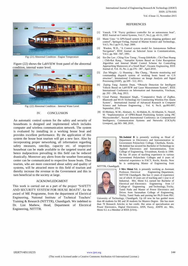
Fig: (21) Abnormal Condition - Engine Temperature
Figure (22) shows the LabVIEW front panel of the abnormal
condition, internal water level.
Fig: (22) Abnormal Condition – Internal Water Level
IV. CONCLUSION
An automatic control system for the safety and security of
houseboats is designed and implemented which includes
computer and wireless communication network. The system
is evaluated by installing in a working house boat and
provides excellent performance. By the application of this
system the house boat tourism will get a new face. Also by
incorporating proper networking, all information regarding
safety measures, rate/day, capacity etc. of respective
houseboat can be made available to the targeted tourist and
hence malpractices prevailing in this field can be reduced
drastically. Moreover any alerts from the weather forecasting
center can be communicated to respective house boats. Thus
tourists, who are more concerned about safety and quality of
systems, will be attracted more to this field of tourism and
thereby increase the revenue to the Government and this in
turn beneficial to the society at large.
ACKNOWLEDGMENT
This work is carried out as a part of the project “SAFETY
AND SECURITY SYSTEM FOR HOUSE BOATS”, for the
award of ME Programme, from the department of Electrical
Engineering, National Institute of Technical Teachers’
Training & Research (NITTTR), Chandigarh. We indebted to
Dr. Lini Mathew, Head, Department of Electrical
Engineering, NITTTR.
REFERENCES
[1] Vaneck, T.W “Fuzzy guidance controller for an autonomous boat”, IEEE Journal on Control Systems, Vol.17, No.2, pp. 43-51, 1997.
[2] Mami Ueno “A GPS-based system for precise shipping guidance and control”, Springer-Verlag, Journal of Marine Science and Technology, Vol.5, No.1 pp.9-15, Sept. 2000.
[3] Warden, W.H., “A Control system model for Autonomous Sailboat Navigation”, IEEE Journal on Selected Areas in Communications, Vol.2, pp. 944 - 947, 1991.
[4] Sin-Der Lee ; Ching-Yaw Tzeng ; Young-ZehrKehr ; Chi-Chun Huang ; Chih-Kai Kang., “Autopilot System Based on Color Recognition Algorithm and Internal Model Control Scheme for Controlling Approaching Maneuvers of a Small Boat”, Oceanic Engineering, IEEE Journal of, Vol. 35, No. 2, pp.376 - 387 , April 2010.
[5] Zuo Mingjiu ; Li Huaming ; Shu Chang., “Remote monitoring and commanding dispatch system of working boats based on C/S structure”, International Conference on Image Analysis and Signal Processing (IASP), pp.509 - 512, 2011.
[6] Zeping Fang; Jianmin Duan, “Obstacle Detection for Intelligent Vehicle Based on LabVIEW and Laser Measurement System”, IEEE International Conference on Information and Automation, Yinchuan, pp. 202 - 206, Aug. 2013.
[7] Ujwal Parmar. Sharanjeet Singh., “Comparative Study of ZigBee, Bluetooth and Wi-Fi Technology for Constructing Wireless Fire Alarm System”, International Journal of Advanced Research in Computer Science and Software Engineering, , Vol. 4, No.9, pp.893-897, September, 2014.
[8] El-Medany, W.M.; Alomary, A.; Al-Hakim, R.; Al-Irhayim, S.; Nousif, M. “Implementation of GPRS-Based Positioning System using PIC Microcontroller”, Second International Conference on Computational Intelligence, Communication Systems and Networks (CICSyN) Liverpool,, pp.365- 368, 2010.
Mr.Indulal B is presently working as Head of
Department in Electronics and Instrumentation in Government Polytechnic College, Cherthala, Kerala.
Mr.Indulal has secured his Bachelor of Technology in
Applied Electronics and Instrumentation, from College of Engineering, Trivandrum, Kerala in 1990.
He has 18 years of teaching experience in various
Government Polytechnic Colleges and 4 years of industrial experience in FACT, Kochi, Kerala. Now
he is undergoing Master of Engineering from
NITTTR, Chandigarh. I Mrs Shimi S.L is presently working as Assistant
Professor, Electrical Engineering Department,
NITTTR Chandigarh. She has 11 years of experience out of which 10 years are of teaching and 1 year is of
Industrial. Mrs. Shimi S.L earned her Bachelor of
Electrical and Electronics Engineering from J.J College of Engineering and Technology, Trichy,
Tamil Nadu and Master of Power Electronics and
Drives from Saranathan College of Engineering, Trichy, Tamil Nadu and pursing her Ph.D from PEC
University of Technology, Chandigarh. Up till now he has guided more
than 40 students for BE and 30 students for Masters Degree. She has more than 70 Research Articles to her credit. Her areas of specialization are
Power Electronics, Digital Electronics, ANN, Fuzzy, ANFIS etc. Mrs. Shimi S.L is a Member of IEEE (USA).
Author’s formal photo
International Journal of Engineering Research & Technology (IJERT)
ISSN: 2278-0181
www.ijert.orgIJERTV4IS110235
(This work is licensed under a Creative Commons Attribution 4.0 International License.)
Vol. 4 Issue 11, November-2015
144
Recommended


![Manual PIC 18F4550[1]](https://img.pdfslide.us/doc/110x75/55cf968d550346d0338c4061/manual-pic-18f45501.jpg)


![Analog Mixed Signal Based SoC for Measurement of … · of the soil using PIC 18F4550 microcontroller is developed by SalehaBegum et al [8], where preamplifier, precision rectifier](https://img.pdfslide.us/doc/110x75/5b5d001e7f8b9ac8618d5da9/analog-mixed-signal-based-soc-for-measurement-of-of-the-soil-using-pic-18f4550.jpg)