PIM-1
IMAGE II
© Metal Sales Manufacturing Corporation/ Subject to change without notice/ Effective Date 9/11 800.406.7387 (Corporate Office) • www.metalsales.us.com
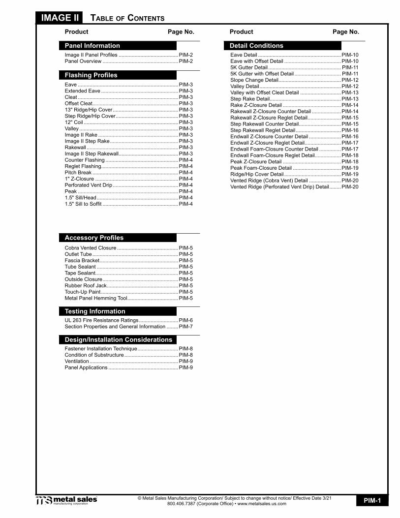
Eave Detail .........................................................PIM-10Eave with Offset Detail .......................................PIM-105K Gutter Detail .................................................. PIM-115K Gutter with Offset Detail ................................ PIM-11Slope Change Detail...........................................PIM-12Valley Detail ........................................................PIM-12Valley with Offset Cleat Detail ............................PIM-13Step Rake Detail.................................................PIM-13Rake Z-Closure Detail ........................................PIM-14Rakewall Z-Closure Counter Detail ....................PIM-14Rakewall Z-Closure Reglet Detail.......................PIM-15Step Rakewall Counter Detail.............................PIM-15Step Rakewall Reglet Detail ...............................PIM-16Endwall Z-Closure Counter Detail ......................PIM-16Endwall Z-Closure Reglet Detail.........................PIM-17Endwall Foam-Closure Counter Detail ...............PIM-17Endwall Foam-Closure Reglet Detail..................PIM-18Peak Z-Closure Detail ........................................PIM-18Peak Foam-Closure Detail .................................PIM-19Ridge/Hip Cover Detail .......................................PIM-19Vented Ridge (Cobra Vent) Detail ......................PIM-20Vented Ridge (Perforated Vent Drip) Detail ........PIM-20
Table of ConTenTs
Product Page No.
Image II Panel Profiles .........................................PIM-2Panel Overview ....................................................PIM-2
Eave .....................................................................PIM-3Extended Eave .....................................................PIM-3Cleat .....................................................................PIM-3Offset Cleat ...........................................................PIM-313" Ridge/Hip Cover .............................................PIM-3Step Ridge/Hip Cover ...........................................PIM-3 12" Coil .................................................................PIM-3Valley ....................................................................PIM-3Image II Rake .......................................................PIM-3Image II Step Rake ...............................................PIM-3Rakewall ...............................................................PIM-3Image II Step Rakewall.........................................PIM-3Counter Flashing ..................................................PIM-4Reglet Flashing.....................................................PIM-4Pitch Break ...........................................................PIM-41" Z-Closure .........................................................PIM-4Perforated Vent Drip .............................................PIM-4Peak .....................................................................PIM-41.5" Sill/Head ........................................................PIM-41.5" Sill to Soffit ....................................................PIM-4
Cobra Vented Closure ..........................................PIM-5Outlet Tube ...........................................................PIM-5Fascia Bracket ......................................................PIM-5Tube Sealant ........................................................PIM-5Tape Sealant.........................................................PIM-5Outside Closure ....................................................PIM-5Rubber Roof Jack .................................................PIM-5Touch-Up Paint .....................................................PIM-5Metal Panel Hemming Tool ...................................PIM-5
UL 263 Fire Resistance Ratings ...........................PIM-6Section Properties and General Information ........PIM-7
Fastener Installation Technique ............................PIM-8Condition of Substructure .....................................PIM-8Ventilation .............................................................PIM-9Panel Applications ................................................PIM-9
Panel Information
Flashing Profiles
Accessory Profiles
Detail Conditions
Product Page No.
Testing Information
Design/Installation Considerations
© Metal Sales Manufacturing Corporation/ Subject to change without notice/ Effective Date 3/21 800.406.7387 (Corporate Office) • www.metalsales.us.com

PIM-2
IMAGE II
© Metal Sales Manufacturing Corporation/ Subject to change without notice/ Effective Date 9/11 800.406.7387 (Corporate Office) • www.metalsales.us.com
© Metal Sales Manufacturing Corporation/ Subject to change without notice/ Effective Date 3/21 800.406.7387 (Corporate Office) • www.metalsales.us.com
Panel overview
PANEL PROFILES
SLOPE
SHEATHING
UNDERLAYMENT
COVERAGE
LENGTH
AVAILABILITY
APPLICATION
FASTENERS
MATERIALS
FINISH
The minimum recommended slope for any Image II roofing panel is 3:12.
Plywood and OSB are the typical sheathing materials. Common plywood thicknesses include 1/2" and 5/8". Common OSB thicknesses include 1/2" and 3/4". To avoid panel distortion, use a properly aligned and uniform substructure. Please note that Image II panels are not recommended for use over open framing.
An underlayment is recommended and required by building codes. 30# felt will meet the minimum performance level. Synthetic underlayments provide improved performance and peel-and-stick underlayments provide further improved performance.
Image II panels are available in a 12" and 16" widths with a 1" rib height.
Minimum panel length is 5'-0". Maximum recommended panel length is 30'-0". Longer panels require additional consideration in packaging, shipping, and erection. Please consult your Metal Sales branch for rec-ommendations (see PGI-2 and 3 for locations).
Image II panels material gauges and finishes vary. Please contact your local branch for options and availability.
Applications include residential, architectural and commercial buildings.
The fastener selection guide should be consulted for choosing proper fasteners for specific applications. Quantity and type of fastener must meet necessary loading and code requirements (see PGI-12-13).
PERFORMANCE TESTUL 2218, UL790, UL263, ASTM E-1592
26 and 24 gauge steel: Grade 50 per ASTM A 792
*Acrylic Coated Galvalume® (ACG) / ASTM A 792Prepainted Galvalume® (ACG), AZ50 per ASTM A 792MS Colorfast45®
**PVDF * Differential appearance of Acrylic Coated Galvalume roofing materials is not a cause for rejection. ** Meets both Kynar 500 and Hylar 5000 specifications.
16" Coverage12" Coverage
16" Coverage12" Coverage
1"
Striations Striations
Minor Ribs
C
C C
C
Minor Ribs
12"
12"
1"
1"
1"
16"
16"

PIM-3
IMAGE II
© Metal Sales Manufacturing Corporation/ Subject to change without notice/ Effective Date 9/11 800.406.7387 (Corporate Office) • www.metalsales.us.com
© Metal Sales Manufacturing Corporation/ Subject to change without notice/ Effective Date 3/21 800.406.7387 (Corporate Office) • www.metalsales.us.com
Length 10'-2" - *Specify Slope Angle
EAVE
flashing Profiles
EXTENDED EAVE CLEAT
OFFSET CLEAT
1/2"
21/2"
C135°
Length 10'-2"
Length 10'-2"
C
Hem
3"X*
5/8"
C
11/2" 1"
1/2"
37/8"
VALLEY
Length 10'-2", 20'-3" - *Specify Slope Angle
RAKEWALL
Length 10'-2"
Hem
C
4"
6"
5/8"
11/2"X*
3" C
Length 10'-2" - *Specify Slope Angle
31/2"
12" COIL IMAGE II RAKE
IMAGE II STEP RAKE IMAGE II STEPRAKEWALL
16" Inside DiameterLength 150'-0"
(For Continuous Gutters)
27/8"
C4"
5/8"
Hem
Hem
11/8"
1"
31/2"
C4"
5/8"3/8"
Length 10'-2", 20'-3"
Length 10'-2", 20'-3"
C4"
Hem11/8"
27/8"1"
Length 10'-2"
C
10"2"X*
13" RIDGE/HIP COVER
1" X*
C
1"
51/2"
Length 10'-2", 20'-3" - *Specify Slope Angle
STEP RIDGE/HIP COVER
31/2"C
1/2"X*
Hem
11/2"
Length 10'-2" - *Specify Slope Angle
PIM-4
IMAGE II
© Metal Sales Manufacturing Corporation/ Subject to change without notice/ Effective Date 9/11 800.406.7387 (Corporate Office) • www.metalsales.us.com
© Metal Sales Manufacturing Corporation/ Subject to change without notice/ Effective Date 3/21 800.406.7387 (Corporate Office) • www.metalsales.us.com
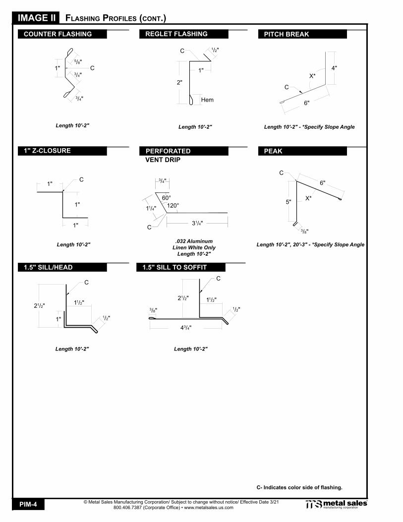
REGLET FLASHING
PERFORATED
1/2"C
1"
2"
Hem
Length 10'-2"
31/4"
3/4"
60°
C 3/8"
6"
5" X*
Length 10'-2", 20'-3" - *Specify Slope Angle
C
.032 AluminumLinen White Only
Length 10'-2"
PEAK
flashing Profiles (ConT.)
1.5" SILL/HEAD 1.5" SILL TO SOFFIT
C
6"
X*4"
Length 10'-2" - *Specify Slope Angle
Length 10'-2" Length 10'-2"
1" Z-CLOSURE
Length 10'-2"
C- Indicates color side of flashing.
C
1" 1/2"
21/2" 11/2"
C
3/8"
43/4"
1/2"
21/2" 11/2"
1"
1"
1"C
COUNTER FLASHING
1" C
3/4"
3/4"
5/8"
Length 10'-2"
PITCH BREAK
VENT DRIP
11/4" 120°

PIM-5
IMAGE II
© Metal Sales Manufacturing Corporation/ Subject to change without notice/ Effective Date 9/11 800.406.7387 (Corporate Office) • www.metalsales.us.com
aCCessory Profiles
TUBE SEALANT
10.3 oz. CartridgeUrethane
TAPE SEALANT
7/8" X 3/16" X 25'Double BeadButyl - Gray
MINI (1/4" to 11/8" O.D. Pipe)#2 (13/4" to 3" O.D. Pipe)#4 (3" to 6" O.D. Pipe)#6 (6" to 9" O.D. Pipe)#8 (7" to 13" O.D. Pipe)
RUBBER ROOF JACK TOUCH-UP PAINT
Available in pintsPVDF / MS Colorfast45
METAL PANELHEMMING TOOL
OUTLET TUBE 2" X 3" FACIA BRACKET
OUTSIDE CLOSURE
COBRA VENTEDCLOSURE
C
1"
36"
36"

PIM-6
IMAGE II
© Metal Sales Manufacturing Corporation/ Subject to change without notice/ Effective Date 9/11 800.406.7387 (Corporate Office) • www.metalsales.us.com
Ul 263 fire resisTanCe raTings
METAL SALES MFG CORP R9697
Mechanically attached metal roof panels - Type “Image II”
For use in Design Nos. P224 , P225 , P227 , P230 , P237 , P508 , P510 , P512 , P701 , P711 , P712 , P713 , P715 , P717 , P720 , P722 , P723 , P724 , P726 , P731 , P734 , P736 , P803 , P814 , P815 , P818 , P819 , P821 , P823 , P824 .
*Hat shaped member to be a minimum of 16 gauge. The member will be fastened through the roof insulation to the steel roof deck with min. No. 14 self-drilling and/or self-tapping fasteners. Spacing to be determined by the structural loading requirements. In addition any compressible UL Classified glass fiber blanket insulation with or without a vapor retarder facing may be used between the speci-fied roof insulation and the metal roof panels.
**Bearing plate to be a minimum of 16 gauge. Member will be fastened through the roof insulation to the steel deck with min. No. 14 self-drilling and/or self-tapping fasteners.
See the UL Fire Resistance Directory for explanation of each design number listed above.
Metal Roof Deck Panels
Metal Sales Manufacturing Corporation has obtained fire resistance ratings for various products conducted according to test criteria set forth by 'Underwriters Laboratories' "Standard Fire Tests of Building Construction and Material" (ANSI/UL 263). This test procedure is identical to ASTM E-119 and NFPA 251.
The fire resistance rating is for the total assembly and not just the external metal panel. Ratings are expressed in hours and vary depending upon the assemblies.In general, the test criteria is to evaluate the assembly's ability to continue to support the super-imposed loads and resist the passage of flame, high temperatures, or hot gases which will ignite combustible materials. The test assemblies are identified by an alpha-numeric design number.
For detail information on specific assemblies and hourly ratings see UL Fire Resistance Direc-tory.
Underwriters Laboratories Inc. ®UL®
LISTED
PIM-7
IMAGE II
© Metal Sales Manufacturing Corporation/ Subject to change without notice/ Effective Date 9/11 800.406.7387 (Corporate Office) • www.metalsales.us.com
© Metal Sales Manufacturing Corporation/ Subject to change without notice/ Effective Date 3/21 800.406.7387 (Corporate Office) • www.metalsales.us.com
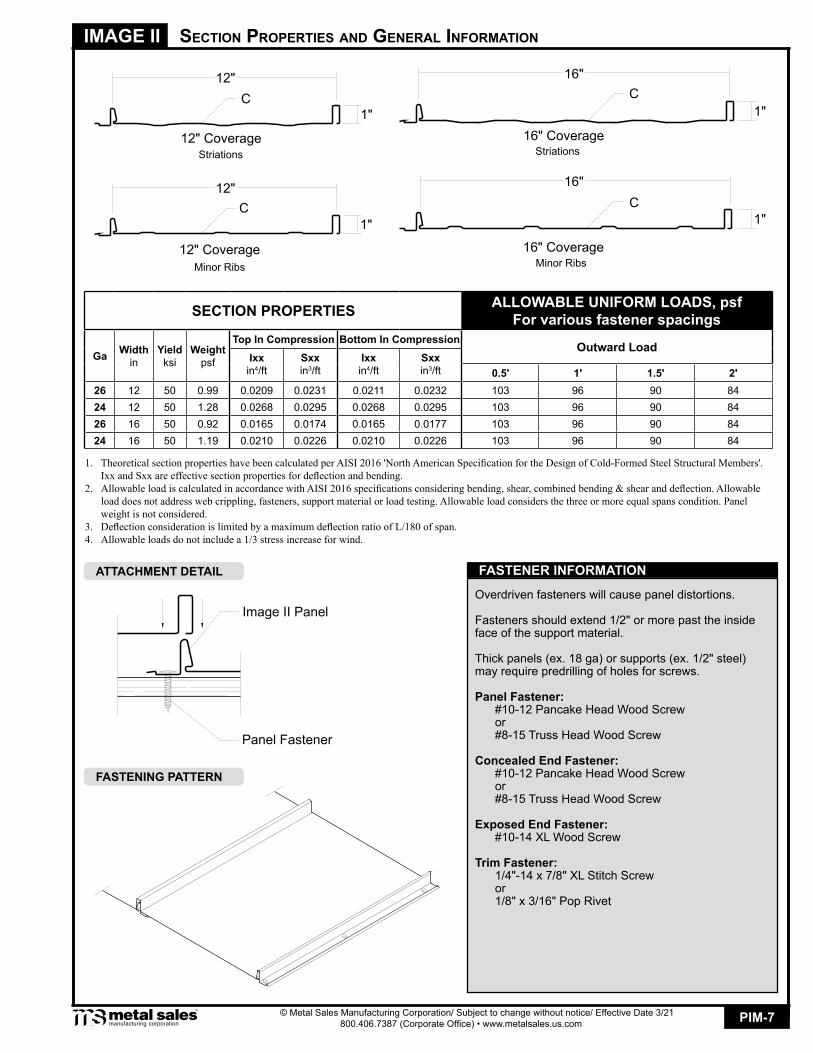
seCTion ProPerTies and general informaTion
16" Coverage12" Coverage
16" Coverage12" Coverage
1"
Striations Striations
Minor Ribs
C
C C
C
Minor Ribs
12"
12"
1"
1"
1"
16"
16"
FASTENER INFORMATIONATTACHMENT DETAIL
FASTENING PATTERN
SECTION PROPERTIES ALLOWABLE UNIFORM LOADS, psfFor various fastener spacings
Ga Widthin
Yieldksi
Weightpsf
Top In Compression Bottom In Compression Outward LoadIxxin4/ft
Sxxin3/ft
Ixxin4/ft
Sxxin3/ft 0.5' 1' 1.5' 2'
26 12 50 0.99 0.0209 0.0231 0.0211 0.0232 103 96 90 8424 12 50 1.28 0.0268 0.0295 0.0268 0.0295 103 96 90 8426 16 50 0.92 0.0165 0.0174 0.0165 0.0177 103 96 90 8424 16 50 1.19 0.0210 0.0226 0.0210 0.0226 103 96 90 84
1. TheoreticalsectionpropertieshavebeencalculatedperAISI2016'NorthAmericanSpecificationfortheDesignofCold-FormedSteelStructuralMembers'. IxxandSxxareeffectivesectionpropertiesfordeflectionandbending.2. AllowableloadiscalculatedinaccordancewithAISI2016specificationsconsideringbending,shear,combinedbending&shearanddeflection.Allowable loaddoesnotaddresswebcrippling,fasteners,supportmaterialorloadtesting.Allowableloadconsidersthethreeormoreequalspanscondition.Panel weightisnotconsidered.3. DeflectionconsiderationislimitedbyamaximumdeflectionratioofL/180ofspan.4. Allowableloadsdonotincludea1/3stressincreaseforwind.
Overdriven fasteners will cause panel distortions.
Fasteners should extend 1/2" or more past the inside face of the support material.
Thick panels (ex. 18 ga) or supports (ex. 1/2" steel) may require predrilling of holes for screws.
Panel Fastener: #10-12 Pancake Head Wood Screw or #8-15 Truss Head Wood Screw
Concealed End Fastener: #10-12 Pancake Head Wood Screw or #8-15 Truss Head Wood Screw
Exposed End Fastener: #10-14 XL Wood Screw Trim Fastener: 1/4"-14 x 7/8" XL Stitch Screw or 1/8" x 3/16" Pop Rivet
Image II Panel
Panel Fastener

PIM-8
IMAGE II
© Metal Sales Manufacturing Corporation/ Subject to change without notice/ Effective Date 9/11 800.406.7387 (Corporate Office) • www.metalsales.us.com
design / insTallaTion ConsideraTions
To prevent wobbling - Make sure fastener head is completely engaged in the socket. If the head does not go all the way in the socket - tap the magnet deeper into the socket to allow full head engagement. Metal chips will build up from drilling and should be removed from time to time.Protect drill point - Push only hard enough on the screw gun to engage clutch. This prevents excess friction and burn out of the drill point. Correct pressure will allow screw to drill and tap without binding.Drilling through sheet and insulation - Ease up on pressure when drilling through insulation to avoid striking the purlin or girt with the point - apply more pressure after drill point contacts purlin or girt.Drilling through purlin overlaps - Drilling through lapped purlins requires extra care. Excessive voids between purlins some-times damages drill points and two self-drillers might be necessary to complete the operation. It is sometimes advantageous to predrill.
Recommended Tool Type - Use depth locating nose or adjustable clutch on screw gun to prevent overdrilling and strip out. Do not use impact tools or runners.Seating the washer - Apply sufficient torque to seat the washer - do not overdrive the fastener.
FASTENER INSTALLATION TECHNIQUE
Whether over solid substrate or open structural framing, panel distortion may occur if not applied over properly aligned and uniform substructure.
The installer should check the roof deck for squareness before installing Image II panels. Several methods can be used to verify squareness of the structure for proper installation of the panels.
METHOD "A" - One method for checking the roof for squareness is to measure diagonally across one slope of the roof from similar points at the ridge and eave and obtain the same dimension.
METHOD "B" - The 3-4-5 triangle system may also be used. To use this system measure a point from the corner along the edge of the roof at a module of three (3). Measure a point from the same corner along another edge at a module of four (4). Then by measuring diagonally between the two points established, the dimension should be exactly a module of five (5) to have a square corner. Multiple uses of this system may be required to determine building squareness. If the endwall cannot be made square, the roof system cannot be installed as shown in these instructions.
CONDITION OF SUBSTRUCTURE
METHOD A
METHOD B4
30
30
35
TOO LOOSESealing material is not visible;not enough compression to
seal properly.
CORRECTSealing material slightly vis-ible at edge of metal washer.
Assembly is watertight.
TOO TIGHTMetal washer deformed; sealing material pressed
beyond washer edge.
WO
OD
SC
RE
W
PIM-9
IMAGE II
© Metal Sales Manufacturing Corporation/ Subject to change without notice/ Effective Date 9/11 800.406.7387 (Corporate Office) • www.metalsales.us.com
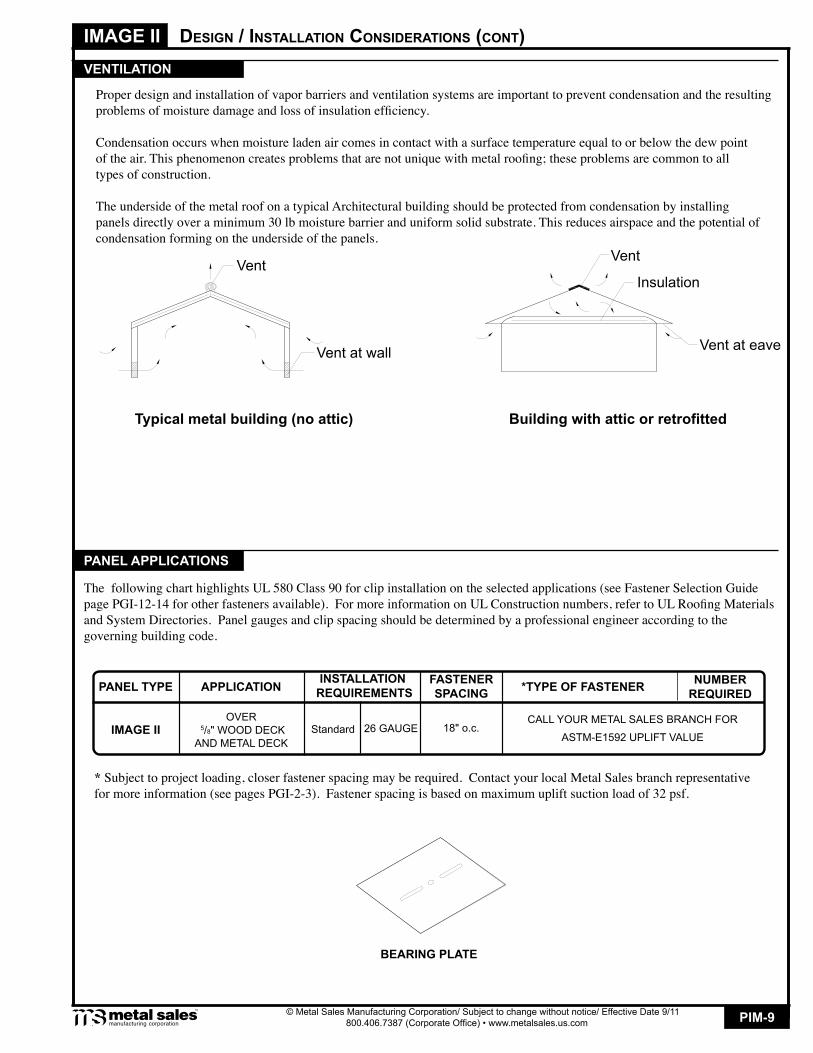
design / insTallaTion ConsideraTions (ConT)
Proper design and installation of vapor barriers and ventilation systems are important to prevent condensation and the resulting problems of moisture damage and loss of insulation efficiency.
Condensation occurs when moisture laden air comes in contact with a surface temperature equal to or below the dew point of the air. This phenomenon creates problems that are not unique with metal roofing; these problems are common to all types of construction.
The underside of the metal roof on a typical Architectural building should be protected from condensation by installing panels directly over a minimum 30 lb moisture barrier and uniform solid substrate. This reduces airspace and the potential of condensation forming on the underside of the panels.
VENTILATION
Typical metal building (no attic)
Vent
Vent at wall Vent at eave
Building with attic or retrofitted
Vent
Insulation
PANEL APPLICATIONS
The following chart highlights UL 580 Class 90 for clip installation on the selected applications (see Fastener Selection Guide page PGI-12-14 for other fasteners available). For more information on UL Construction numbers, refer to UL Roofing Materials and System Directories. Panel gauges and clip spacing should be determined by a professional engineer according to the governing building code.
* Subject to project loading, closer fastener spacing may be required. Contact your local Metal Sales branch representative for more information (see pages PGI-2-3). Fastener spacing is based on maximum uplift suction load of 32 psf.
BEARING PLATE
CALL YOUR METAL SALES BRANCH FOR
ASTM-E1592 UPLIFT VALUE18" o.c.
OVER 5/8" WOOD DECKAND METAL DECK
Standard 26 GAUGEIMAGE II
NUMBER REQUIRED*TYPE OF FASTENERAPPLICATION INSTALLATION
REQUIREMENTSFASTENERSPACINGPANEL TYPE
PIM-10
IMAGE II
© Metal Sales Manufacturing Corporation/ Subject to change without notice/ Effective Date 9/11 800.406.7387 (Corporate Office) • www.metalsales.us.com
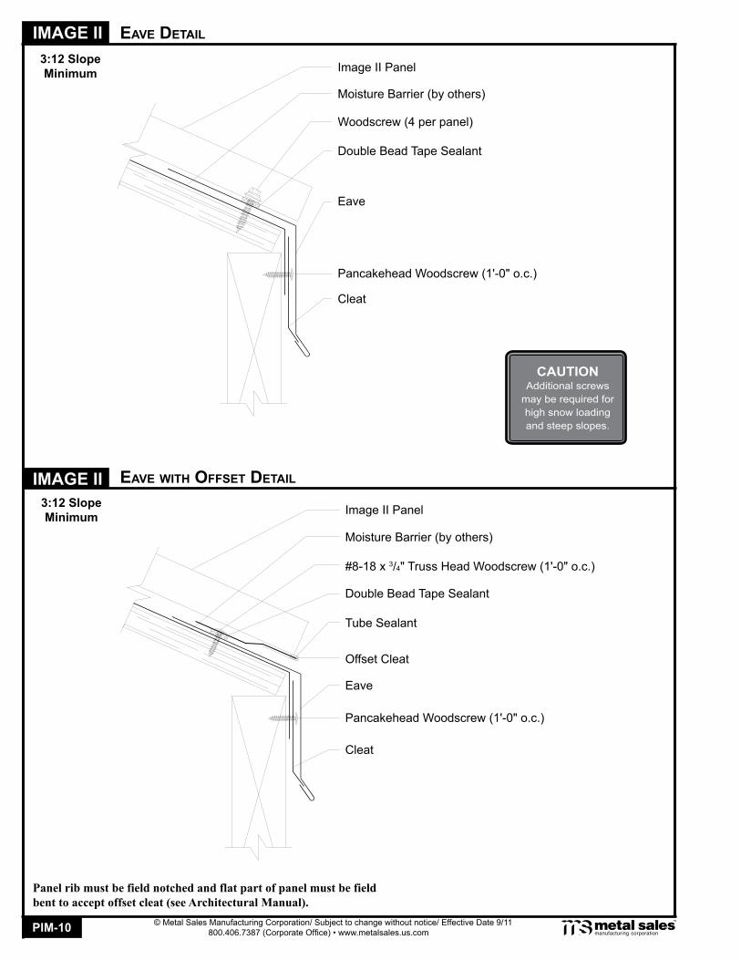
eave deTail
eave wiTh offseT deTail
3:12 SlopeMinimum
Pancakehead Woodscrew (1'-0" o.c.)
Double Bead Tape Sealant
Cleat
Image II Panel
Moisture Barrier (by others)
Eave
Woodscrew (4 per panel)
image ii
Panel rib must be field notched and flat part of panel must be field bent to accept offset cleat (see Architectural Manual).
3:12 SlopeMinimum
#8-18 x 3/4" Truss Head Woodscrew (1'-0" o.c.)
Double Bead Tape Sealant
Cleat
Image II Panel
Moisture Barrier (by others)
Eave
Tube Sealant
Pancakehead Woodscrew (1'-0" o.c.)
Offset Cleat
CAUTIONAdditional screws
may be required for high snow loading and steep slopes.

PIM-11
IMAGE II
© Metal Sales Manufacturing Corporation/ Subject to change without notice/ Effective Date 9/11 800.406.7387 (Corporate Office) • www.metalsales.us.com
image ii
5K gUTTer deTail
5K gUTTer wiTh offseT deTail
Double Bead Tape Sealant
Image II Panel
Moisture Barrier (by others)
5K Gutter (by others)
Woodscrew (4 per panel)
Eave
Double Bead Tape Sealant
Image II Panel
Moisture Barrier (by others)
Tube Sealant
5K Gutter (by others)
Offset Cleat
Eave
Pancakehead Woodscrew (1'-0" o.c.)
Panel rib must be field notched and flat part of panel must be field bent to accept offset cleat (see Architectural Manual).
3:12 SlopeMinimum
3:12 SlopeMinimum
CAUTIONAdditional screws
may be required for high snow loading and steep slopes.
Woodscrew (1'-0" o.c.)
Fascia Bracket
Woodscrew (1'-0" o.c.)
Fascia Bracket

PIM-12
IMAGE II
© Metal Sales Manufacturing Corporation/ Subject to change without notice/ Effective Date 9/11 800.406.7387 (Corporate Office) • www.metalsales.us.com
sloPe Change deTail
3"
image ii valley deTail
Double Bead Tape Sealant
Image II Panel
Moisture Barrier (by others)Tube SealantOffset CleatPancakehead Woodscrew (1'-0" o.c.)
Image II Panel
Pitch BreakPancakehead Woodscrew (1'-0" o.c.)
Z-Closure
1/8" x 3/16" Pop-Rivet (3 per panel)
Double Bead Tape Sealant
Panel rib must be field notched and flat part of panel must be field bent to accept offset cleat (see Architectural Manual).
Image II Panel
Moisture Barrier (by others)Valley
Double Bead Tape SealantWoodscrew (4 per panel)
3"
3:12 SlopeMinimum
3:12 SlopeMinimum
CAUTIONAdditional screws
may be required for high snow loading and steep slopes.
Note: Z-Closures must be field cut and bent to fit between panel ribs (see Architectural Manual).
PIM-13
IMAGE II
© Metal Sales Manufacturing Corporation/ Subject to change without notice/ Effective Date 9/11 800.406.7387 (Corporate Office) • www.metalsales.us.com
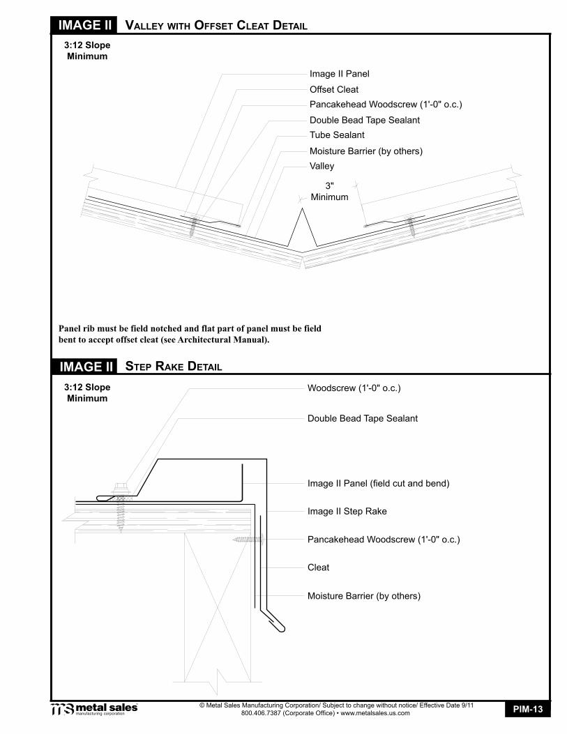
valley wiTh offseT CleaT deTail
sTeP raKe deTail
3:12 SlopeMinimum
image ii
Image II Panel
Moisture Barrier (by others)Valley
Double Bead Tape Sealant
3"Minimum
Tube Sealant
Offset CleatPancakehead Woodscrew (1'-0" o.c.)
Panel rib must be field notched and flat part of panel must be field bent to accept offset cleat (see Architectural Manual).
Double Bead Tape Sealant
Image II Panel (field cut and bend)
Moisture Barrier (by others)
Image II Step Rake
Pancakehead Woodscrew (1'-0" o.c.)
Cleat
Woodscrew (1'-0" o.c.)
3:12 SlopeMinimum
PIM-14
IMAGE II
© Metal Sales Manufacturing Corporation/ Subject to change without notice/ Effective Date 9/11 800.406.7387 (Corporate Office) • www.metalsales.us.com
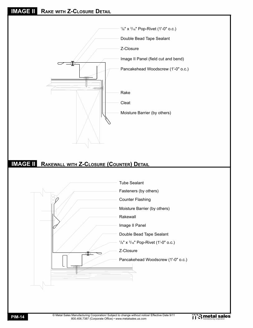
raKe wiTh Z-ClosUre deTail
image ii raKewall wiTh Z-ClosUre (CoUnTer) deTail
Double Bead Tape Sealant
Image II Panel (field cut and bend)
Moisture Barrier (by others)
Rake
Pancakehead Woodscrew (1'-0" o.c.)
Cleat
1/8" x 3/16" Pop-Rivet (1'-0" o.c.)
Z-Closure
Double Bead Tape Sealant
Image II Panel
Moisture Barrier (by others)
Rakewall
Pancakehead Woodscrew (1'-0" o.c.)
1/8" x 3/16" Pop-Rivet (1'-0" o.c.)
Z-Closure
Counter Flashing
Fasteners (by others)
Tube Sealant
PIM-15
IMAGE II
© Metal Sales Manufacturing Corporation/ Subject to change without notice/ Effective Date 9/11 800.406.7387 (Corporate Office) • www.metalsales.us.com
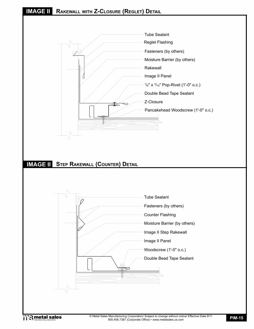
raKewall wiTh Z-ClosUre (regleT) deTail
sTeP raKewall (CoUnTer) deTail
Reglet Flashing
image ii
Double Bead Tape Sealant
Image II Panel
Moisture Barrier (by others)
Rakewall
1/8" x 3/16" Pop-Rivet (1'-0" o.c.)
Z-Closure
Fasteners (by others)
Tube Sealant
Double Bead Tape Sealant
Image II Panel
Moisture Barrier (by others)
Image II Step Rakewall
Counter Flashing
Fasteners (by others)
Tube Sealant
Woodscrew (1'-0" o.c.)
Pancakehead Woodscrew (1'-0" o.c.)

PIM-16
IMAGE II
© Metal Sales Manufacturing Corporation/ Subject to change without notice/ Effective Date 9/11 800.406.7387 (Corporate Office) • www.metalsales.us.com
sTeP raKewall (regleT) deTail
endwall wiTh Z-ClosUre (CoUnTer) deTail
Fasteners (by others)
Reglet Flashing
Tube Sealant
image ii
Double Bead Tape Sealant
Image II Panel (field cut and bend)
Moisture Barrier (by others)
Image II Step Rakewall
Tube Sealant
Pancakehead Woodscrew (1'-0" o.c.)
Fasteners (by others)
Double Bead Tape Sealant
Image II Panel
Moisture Barrier (by others)
Pitch Break
Counter Flashing
Pancakehead Woodscrew (4 per panel)
Tube Sealant
1/8" x 3/16" Pop-Rivet (3 per panel)
Z-Closure
CAUTIONAdditional screws
may be required for high snow loading and steep slopes.
Note: Z-Closures must be field cut and bent to fit between panel ribs (see Architectural Manual).

PIM-17
IMAGE II
© Metal Sales Manufacturing Corporation/ Subject to change without notice/ Effective Date 9/11 800.406.7387 (Corporate Office) • www.metalsales.us.com
endwall wiTh Z-ClosUre (regleT) deTail
endwall wiTh foam-ClosUre (CoUnTer) deTailimage ii
Fasteners (by others)
Tube Sealant
Double Bead Tape Sealant
Image II Panel
Moisture Barrier (by others)
Pitch Break
Reglet Flashing
Pancakehead Woodscrew (4 per panel)Tube Sealant
1/8" x 3/16" Pop-Rivet (3 per panel)
Z-Closure
Fasteners (by others)
Tube Sealant
Double Bead Tape Sealant
Image II Panel
Moisture Barrier (by others)
Pitch Break
Counter Flashing
1/8" x 3/16" Pop-Rivet (1'-0" o.c.)
Image II Outside Closure
Double Bead Tape Sealant
3:12 SlopeMinimum
3:12 SlopeMinimum
CAUTIONAdditional screws
may be required for high snow loading and steep slopes.
CAUTIONAdditional screws
may be required for high snow loading and steep slopes.
Note: Z-Closures must be field cut and bent to fit between panel ribs (see Architectural Manual).

PIM-18
IMAGE II
© Metal Sales Manufacturing Corporation/ Subject to change without notice/ Effective Date 9/11 800.406.7387 (Corporate Office) • www.metalsales.us.com
endwall wiTh foam-ClosUre (regleT) deTail
image ii PeaK wiTh Z-ClosUre deTail
Fasteners (by others)
Tube Sealant
Double Bead Tape Sealant
Image II Panel
Moisture Barrier (by others)
Pitch Break
Reglet Flashing
1/8" x 3/16" Pop-Rivet (every rib)
Image II Outside Closure
Double Bead Tape Sealant
Double Bead Tape Sealant
Image II Panel
Moisture Barrier (by others)
Peak
Z-Closure
1/8" x 3/16" Pop-Rivet (3 per panel)
Tube Sealant
Cleat
#8-18 x 3/4" Truss Head Woodscrew (4 per panel)
3:12 SlopeMinimum
3:12 SlopeMinimum
CAUTIONAdditional screws
may be required for high snow loading and steep slopes.
CAUTIONAdditional screws
may be required for high snow loading and steep slopes.
Pancakehead Woodscrew (1'-0" o.c.)
Note: Z-Closures must be field cut and bent to fit between panel ribs (see Architectural Manual).

PIM-19
IMAGE II
© Metal Sales Manufacturing Corporation/ Subject to change without notice/ Effective Date 9/11 800.406.7387 (Corporate Office) • www.metalsales.us.com
PeaK wiTh foam-ClosUre deTail
image ii ridge/hiP Cover deTail
Double Bead Tape Sealant
Image II Panel
Moisture Barrier (by others)
1/8" x 3/16" Pop-Rivet (every rib)
Image II Outside Closure
Double Bead Tape Sealant
Image II Panel
Peak
Z-Closure
1/8" x 3/16" Pop-Rivet (3 per panel)
Tube Sealant
Cleat
Pancakehead Woodscrew (4 per panel)
Double Bead Tape Sealant
Double Bead Tape Sealant
10" Step Ridge/Hip Cover
3:12 SlopeMinimum
3:12 SlopeMinimum
Pancakehead Head Woodscrew (1'-0" o.c.)
CAUTIONAdditional screws
may be required for high snow loading and steep slopes.
CAUTIONAdditional screws
may be required for high snow loading and steep slopes.
Moisture Barrier (by others)
Note: Z-Closures must be field cut and bent to fit between panel ribs (see Architectural Manual).

PIM-20
IMAGE II
© Metal Sales Manufacturing Corporation/ Subject to change without notice/ Effective Date 9/11 800.406.7387 (Corporate Office) • www.metalsales.us.com
venTed ridge (Cobra venT) deTail
image ii venTed ridge (PerforaTed venT driP) deTail
Double Bead Tape Sealant
Image II Panel
Moisture Barrier (by others)
1/8" x 3/16" Pop-Rivet (every rib)
Cobra Vented Closure
13" Step Ridge/Hip Cover
2" Max
13" Step Ridge/Hip Cover
Image II Outside Closure
1/8" x 3/16" Pop-Rivet (1'-0" o.c.)
Perforated Vent Drip
Image II Panel
3:12 SlopeMinimum
3:12 SlopeMinimum
CAUTIONAdditional screws
may be required for high snow loading and steep slopes.
CAUTIONAdditional screws
may be required for high snow loading and steep slopes.
2" Max
Moisture Barrier (by others)
1/8" x 3/16" Pop-Rivet (every rib)
Recommended