IMA: THE INTELLIGENT MACHINE ARCHITECTURE
By
Robert Todd Pack
Dissertation
Submitted to the Faculty of the
Graduate School of Vanderbilt University
in partial fulfillment of the requirements
for the degree of
DOCTOR OF PHILOSOPHY
in
Electrical and Computer Engineering
March 2003
Nashville, Tennessee
Approved: Date:

ACKNOWLEDGEMENTS
I thank Dr. K. Kawamura for believing in my ideas enough to let me lead his
robotics lab into the new area of architecture-driven software design.
I thank my committee for their comments, reviews and suggestions that con-
tributed to this effort.
I thank my wonderful wife, Ruth, for putting up with me during this very long
journey.
Finally, I thank God for the ability and the inspiration to develop new con-
tributions to the area of robotics. He has continually guided me back to the idea
of robots and I pray that this work will contribute in some small way to the de-
velopment of service robots that relieve pain and suffering, aid those in need of
assistance, or provide companionship to those who are alone.
ii

TABLE OF CONTENTS
Page
ACKNOWLEDGEMENTS . . . . . . . . . . . . . . . . . . . . . . . . . . . ii
LIST OF FIGURES . . . . . . . . . . . . . . . . . . . . . . . . . . . . . . . vi
LIST OF TABLES . . . . . . . . . . . . . . . . . . . . . . . . . . . . . . . . viii
Chapter
I. INTRODUCTION . . . . . . . . . . . . . . . . . . . . . . . . . . . . 1
Background . . . . . . . . . . . . . . . . . . . . . . . . . . . . . . . 2Research Objectives . . . . . . . . . . . . . . . . . . . . . . . . . . 6Assumptions . . . . . . . . . . . . . . . . . . . . . . . . . . . . . . 9Summary of Research . . . . . . . . . . . . . . . . . . . . . . . . . 10Organization of Dissertation . . . . . . . . . . . . . . . . . . . . . 12
II. SOFTWARE ARCHITECTURE FOR INTELLIGENT ROBOTICS 14
Background . . . . . . . . . . . . . . . . . . . . . . . . . . . . . . . 14Software Architecture . . . . . . . . . . . . . . . . . . . . . . 15System Complexity and Decomposition . . . . . . . . . . . . 17Integration and Arbitration . . . . . . . . . . . . . . . . . . 18
Robot Software Architectures . . . . . . . . . . . . . . . . . . . . . 21Knowledge-Based Architectures . . . . . . . . . . . . . . . . . . . . 22Behavior-Based Architectures . . . . . . . . . . . . . . . . . . . . . 28Hybrid Architectures . . . . . . . . . . . . . . . . . . . . . . . . . 37Multi-Agent Architectures . . . . . . . . . . . . . . . . . . . . . . . 43Discussion of Issues . . . . . . . . . . . . . . . . . . . . . . . . . . 49
III. OVERVIEW OF THE INTELLIGENT MACHINE ARCHITECTURE 51
Introduction . . . . . . . . . . . . . . . . . . . . . . . . . . . . . . 51Robot-Environment Model . . . . . . . . . . . . . . . . . . . . . . 56
Agents . . . . . . . . . . . . . . . . . . . . . . . . . . . . . . 57Relationships . . . . . . . . . . . . . . . . . . . . . . . . . . 60
Agent-Object Model . . . . . . . . . . . . . . . . . . . . . . . . . . 61Code Development Framework . . . . . . . . . . . . . . . . . . . . 65
IV. ROBOT-ENVIRONMENT MODEL IN THE IMA . . . . . . . . . . 69
Introduction . . . . . . . . . . . . . . . . . . . . . . . . . . . . . . 69IMA Agents . . . . . . . . . . . . . . . . . . . . . . . . . . . . . . 70
Intelligent Service Robot Domain Agents . . . . . . . . . . . 71
iii
Conceptual Agent Interaction Model . . . . . . . . . . . . . 72IMA Relationships . . . . . . . . . . . . . . . . . . . . . . . . . . . 75
Classification of Relationship Types . . . . . . . . . . . . . . 77
V. AGENT-OBJECT MODEL IN THE IMA . . . . . . . . . . . . . . . 81
Introduction . . . . . . . . . . . . . . . . . . . . . . . . . . . . . . 81Structured Object-Oriented Model . . . . . . . . . . . . . . . . . . 88
VI. EXAMPLE SYSTEMS USING THE IMA . . . . . . . . . . . . . . . 96
ISAC: Dual-Armed Humanoid Robot . . . . . . . . . . . . . . . . . 96Helpmate: Mobile Manipulator . . . . . . . . . . . . . . . . . . . . 97
VII. EVALUATION OF THE ARCHITECTURE . . . . . . . . . . . . . 99
VIII. CONCLUSIONS AND FUTURE RESEARCH . . . . . . . . . . . . 101
Appendix
A. DEFINITIONS OF IMA TERMS . . . . . . . . . . . . . . . . . . . 102
IMA Terminology . . . . . . . . . . . . . . . . . . . . . . . . . . . 102
B. ROBOTICS TERMINOLOGY . . . . . . . . . . . . . . . . . . . . . 112
C. UML NOTATION . . . . . . . . . . . . . . . . . . . . . . . . . . . . 113
Class Diagrams . . . . . . . . . . . . . . . . . . . . . . . . . . . . . 113Sequence Diagrams . . . . . . . . . . . . . . . . . . . . . . . . . . 114State Diagrams . . . . . . . . . . . . . . . . . . . . . . . . . . . . . 114
D. COMPONENT OBJECT SOFTWARE . . . . . . . . . . . . . . . . 115
The Component Object Model (COM) . . . . . . . . . . . . . . . . 116Special COM / OLE Interfaces . . . . . . . . . . . . . . . . . . . . 118
E. USING THE CODE FRAMEWORK . . . . . . . . . . . . . . . . . . 122
Introduction . . . . . . . . . . . . . . . . . . . . . . . . . . . . . . 122Writing Simple Agent Components . . . . . . . . . . . . . . . . . . 124Writing Representation Components . . . . . . . . . . . . . . . . . 124Writing Relationship Components . . . . . . . . . . . . . . . . . . 124Writing Component Managers . . . . . . . . . . . . . . . . . . . . 124Writing Agent Shell Programs . . . . . . . . . . . . . . . . . . . . 124
iv
Writing Agent Tools . . . . . . . . . . . . . . . . . . . . . . . . . . 126
F. SYNCHRONIZATION MECHANISM . . . . . . . . . . . . . . . . . 127
REFERENCES . . . . . . . . . . . . . . . . . . . . . . . . . . . . . . . . . . 130
v
LIST OF FIGURES
Figure Page
1. Action Selection Problem . . . . . . . . . . . . . . . . . . . . . . . . 21
2. SMPA Approach [17] . . . . . . . . . . . . . . . . . . . . . . . . . . 24
3. Utility-Based Agent [11] . . . . . . . . . . . . . . . . . . . . . . . . 24
4. InteRRap Architecture [67] . . . . . . . . . . . . . . . . . . . . . . . 27
5. Behavior-Based Approach [17] . . . . . . . . . . . . . . . . . . . . . 29
6. Agent Network Architecture [59] . . . . . . . . . . . . . . . . . . . 31
7. Blumberg’s Behavioral Architecture [13] . . . . . . . . . . . . . . . 33
8. AuRA Architecture [6] . . . . . . . . . . . . . . . . . . . . . . . . . 36
9. Motion Schema Concept from Arkin [6] . . . . . . . . . . . . . . . 36
10. RCS Layer [2] . . . . . . . . . . . . . . . . . . . . . . . . . . . . . 39
11. GLAIR Architecture [48] . . . . . . . . . . . . . . . . . . . . . . . 41
12. CIRCA Architecture [68] . . . . . . . . . . . . . . . . . . . . . . . 42
13. ISAC 2 System [10] . . . . . . . . . . . . . . . . . . . . . . . . . . 46
14. Suehiro’s Agent Network [87] . . . . . . . . . . . . . . . . . . . . . 47
15. JANUS Architecture [12] . . . . . . . . . . . . . . . . . . . . . . . 48
16. Map of Robot Architectures . . . . . . . . . . . . . . . . . . . . . . 50
17. IMA Development Process . . . . . . . . . . . . . . . . . . . . . . . 55
18. Correspondence of IMA Agents to System-Level Entities . . . . . . 57
19. IMA Agent Internal Structure . . . . . . . . . . . . . . . . . . . . . 66
20. IMA Agent Classifications . . . . . . . . . . . . . . . . . . . . . . . 73
21. Asynchronous Decision and Computation Processes . . . . . . . . . 74
vi
22. Asymmetric Agent Relationships in IMA . . . . . . . . . . . . . . . 79
23. Symmetric Agent Relationships in IMA . . . . . . . . . . . . . . . . 80
24. Structural Aspect . . . . . . . . . . . . . . . . . . . . . . . . . . . . 85
25. Functional Aspect . . . . . . . . . . . . . . . . . . . . . . . . . . . . 86
26. Policy Aspect . . . . . . . . . . . . . . . . . . . . . . . . . . . . . . 87
27. Simple Data Flow . . . . . . . . . . . . . . . . . . . . . . . . . . . . 89
28. More Complex Connection . . . . . . . . . . . . . . . . . . . . . . . 90
29. Fully Symetric Relationship . . . . . . . . . . . . . . . . . . . . . . 91
30. Agent-Object Model: Top Level Class Diagram . . . . . . . . . . . 92
31. Agent-Object Model: Loading Sequence Diagram . . . . . . . . . . 93
32. Agent-Object Model: Component State Diagram . . . . . . . . . . 94
33. Detail of Relationships and Contributions . . . . . . . . . . . . . . 95
34. Agent-Network for ISAC Demo . . . . . . . . . . . . . . . . . . . . 97
35. Agent-Network for Helpmate Demo . . . . . . . . . . . . . . . . . . 98
36. UML Model of COM . . . . . . . . . . . . . . . . . . . . . . . . . . 119
37. UML Model IDispatch . . . . . . . . . . . . . . . . . . . . . . . . . 121
38. UML Model of Framework Base Classes . . . . . . . . . . . . . . . 125
39. Agent Time Synchronization Mechanism . . . . . . . . . . . . . . . 128
vii
LIST OF TABLES
Table Page
1. Summary of Architectural Properties . . . . . . . . . . . . . . . . . 49
viii
CHAPTER I
INTRODUCTION
This work investigates the problem of designing software for intelligent ma-
chines, such as service robots. Intelligent machines get information from a set
sensors and control a set of actuators. Intelligent machines incorporate the ability
to react to changes in their environment, incorporate a-priori knowledge and work
to complete tasks. Thus, they are both deliberative and reactive in their operation.
Between the sensors and actuators of an intelligent machine lies a computational
mechanism and software that together must provide paths from sensing to action
that allow the intelligent machine to complete its tasks. The software architecture
of an intelligent machine is a plan for building the software system that resides be-
tween sensors and actuators and utilizes the underlying computing mechanism to
complete its tasks. The resulting software system provides the connection between
sensing and action for the intelligent machine.
Many solutions to the design problem exist and serve a wide variety of robot
development communities. The problem of intelligent service robot control will be
discussed in the context of current approaches, and the contribution of software
architecture will be identified. Next, several available intelligent robot-control ar-
chitectures are described, classified, and compared based on architectural features.
Finally, a new approach to this software design problem that takes advantage of
advances in object-based software engineering is described and evaluated based on
reuse of code and scalability of performance.
This new software architecture is based on a philosophy [51] that places more
1
importance on versatility and extensibility than development of a single, general
mechanism, acknowledges the need for multiple processing paths from robot sen-
sors to robot actuators, provides a way to manage multiple internal representations,
and takes advantage of commonly available computer systems. This new software
architecture guides the development of robot control software and specifies a dis-
tributed network of independent, cooperating and competing software modules
termed agents. These agents and the connections between them form an active
object-oriented model of the physical resources, behaviors, skills, and tasks that
constitute the robot as well as the internal models of robot users and physical
objects in the robot’s environment.
Background
The Intelligent Machine Architecture (IMA) is a software architecture that sup-
ports the development of integrated control software for intelligent service robots
and potentially, other intelligent machines. Thus, this work is the union of soft-
ware architecture and various design approaches for building intelligent robots. It
is also concerned with achieving and maintaining software system integration by
following a software architecture that guides development.
A software architecture is a kind of plan or template for building a related class
of software systems. An architecture provides descriptions of the components and
connections between them at certain levels of abstraction [?]. A system (set of
components and their connections with a purpose) conforms to an architecture if
the contstraints imposed by the architecture are met. Small-scale architectural de-
scriptions (template for building a piece of a system) are called design patterns [23]
2
in the object-oriented design community.
To define “intelligent systems” or “intelligent service robots”, I submit that
these systems utilize sensing to capture relevant aspects of their environment, and
their own internal resources of computation and physical action to achieve some
physical task. Intelligent systems should be characterized purely by observable
intelligent action instead of any special internal features. An intelligent machine
should be able to bring physical, computational, and informational resources to-
gether to complete its tasks.
As a guideline, intelligent service robot behavior should resemble some aspects
of the behavior of animals and humans when presented with similar problems.
Intelligent service robots should be able to use their computational, sensory, and
physical resources to achieve goals and respond to changes in the environment.
Erman has attributed the following properties to intelligent systems [32] and these
properties are quoted again by Booch [14] in the context of software engineering:
• They pursue goals that vary over time.
• They incorporate, use, and maintain knowledge.
• They exploit diverse, ad hoc subsystems embodying a variety of selected
methods.
• They interact intelligently with users and other systems.
• They allocate their own resources and attention.
From the viewpoint of software architecture, the most important characteristic
is the ability to exploit diverse subsystems that embody a variety of methods.
3
This and other experience suggests strongly that there is no one way to implement
the software system for an intelligent machine, so an architecture will need to be
versatile to address this problem. The ability to incorporate, use, and maintain an
internal representation of knowledge is one possible method for guiding behavior
as pointed out in the work of Agre and Chapman [1], and several other methods
have been used successfully by Brooks, et al. [19, 63, 59]. Thus, there is no unique
solution to the problem of creating the software system that exhibits intelligent
behavior on a particular intelligent machine or even agreement on how it might
be achieved. It is likely that the essence of intelligent behavior is the structured
integration of various components in a large and complex system that accounts for
such a diversity of methods.
Service robots are one type of intelligent machine that is designed to interact
with human users in relatively unstructured environments. Other definitions of
the term “robot” include the word “programmable” or “reprogrammable”; for ex-
ample, the robotics frequently asked questions list [30] gives this definition: “A
reprogrammable, multifunctional manipulator designed to move material, parts,
tools or specialized devices through various programmed motions for the perfor-
mance of a variety of tasks.” This reiterates the problem that the robot’s software
system must solve. In contrast, the Random House Dictionary describes a robot
as “An automatic device that performs functions normally ascribed to humans
or a machine in the form of a human.” [91] Thus, the performance goals for an
intelligent robot system are continually increasing in complexity. Ironically, it is
often thought that, as soon as robots can effectively handle a problem, then it is no
longer a challenge since “even robots can do that.” This suggests the criterion that
4

robot software should be designed to evolve over time and have new capabilities
added to it.
McFarland points out that intelligent systems are ultimately characterized by
their externally observable behavior [63], not on the theoretical elegance of their in-
ternal mechanisms. Since we commonly attribute intelligence to animals or people
and have little knowledge of the mechanisms involved, it is a practical measure of
intelligence. This type of definition of intelligence is also attributed to Turing, who
proposed the now famous Turing Test [33]. In this test a machine tries to convince
a person that it is really another person by answering a series of questions from
the real person. This test ignores the fact that intelligent behavior exists in many
forms and that human language understanding is not necessary for intelligence.
However, the common feature of these viewpoints is the idea that intelligence is
accessible only through observing intelligent behavior. For the purpose of design
and development of such systems, the intelligent machine must be viewed as a sys-
tem and the software used in the intelligent machine is a software subsystem. This
software system needs an architecture that can guide development and manage the
complexity of development and improvement over time.
The designer of a robot may want the robot to go down a cluttered hall and not
get stuck, get lost, or do any damage. However, this externally observable behavior
has no simple or unique implementation on a given set of robot hardware. If the
problem or domain is more structured and problem description is more formal,
then methods that deliberate based on logical models are a good match. If the
problems are essentially reactive, like mobile robots in dynamic environments, then
the behavior-based methods can excel because they rely on simple reactive rules
5
to select actions. Many researchers are now combining the these approaches in
the software systems for robot control. This work represents an effort to design
a software architecture that combines support for both types of control and the
progressive development of the software system itself over time.
Research Objectives
Software design for intelligent robotic systems is a large, open-ended problem.
A number of partially successful approaches in current practice address this type
of software design. When given a robot, a machine that is a physically integrated
set of computers, sensors and actuators, it is natural to ask the question, How
can I make this machine intelligent? How can I make it solve problems? Handle
new situations? Interact with humans and other robots? The answer lies in the
control software for the robot. Few existing systems emphasize the importance
of software architecture in the design of the software system despite the fact that
control software is frequently developed based on tacit assumptions that define
how the overall software system will be structured and influences the success of
implementation and improvement over time. Some software systems are intended
to be models of cognitive processes [4] or animal behaviors [63], while others are
based on assuming that the world follows a formal, logical model [35] and some
are essentially ad-hoc [17].
If the desired intelligent behavior of a service robot could be defined directly
in terms of systems of differential equations, modern control theory would be a
powerful tool that would let us build controllers easily. If the domain could be
adequately defined by a set of production rules or statements in the predicate
6
calculus, then classical AI would solve the problem for us by applying symbolic
knowledge of a formal model of the environment and robot. Newer architectures,
like behavior-based AI, let us specify which behaviors we would like, but these ap-
proaches remain controversial because they are thought to be mostly ad hoc. Inter-
actions in such systems are difficult to manage as the software system grows [70].
Few attempts have been made to model the interactions in these systems except for
the work of Kosecka [53] on discrete-event modeling. Intelligent behaviors can be
partially realized by a variety of methods. The specification and expectations for
the behaviors are often imprecise. The complexity of building a software system
to exhibit intelligent behaviors is a design problem that must be managed by an
explicit software architecture.
There is a distinct lack of an accepted approach for building robot software
systems that exhibit intelligent and robust behavior in less structured environ-
ments, like the software for service robots. Instead, a patchwork of disparate
methods are used. This is because many architectures used for intelligent robot
control were originally designed to illustrate the functioning of a single principle,
mechanism, or cognitive model and were pressed into service to help manage the
software system for a robot. At a recent International Conference on Robotics
and Automation panel discussion, systems integration was identified as one of the
grand challenges facing robotics research in the future [28]. These concerns form
the motivation for this work. Needed is an effort to develop new software archi-
tectures that address the problem of building integrated robot control software
systems, take advantage of the wide array of fundamental developments in the
robotics community, draw on the growing field of software engineering, and guide
7

the software development process to manage complexity. This work is in the spirit
of explicit architecture-driven software design that is currently supported by a va-
riety of methods in professional software practice such as object-oriented design
and modeling of systems [14, 76, 39], as well as more formal research projects
on modeling and developing system architectures such as MULTIGRAPH [88, 89]
and architecture-centered design of software systems [41, 3]. Some applications of
object-oriented concepts to design of software for robots have been described in
Configurable Modular Reference Here, Bagchi, others.
The objective of this work is to design a software architecture for intelligent
service robot software systems by bringing previous developments in robot archi-
tectures together with recent advances in software architecture to help manage the
inherent complexity of software development for this domain. Another motiva-
tion for this work is that the search for intelligent behavior in intelligent machines
may be better served by developing an architecture that supports integration of
existing ideas and methods, rather than the search for the “silver bullet” [16] that
will give us intelligent robots. Some conceptual tools are becoming available from
the field of software engineering to help address integration issues. This disser-
tation presents the design of a new software architecture for intelligent service
robot software systems that draws on recent advances in software engineering,
object-oriented modeling and design, and other robot control architectures. This
architecture represents a unique approach to software for robot control for the
following reasons:
• The architecture is designed and expressed using common visual notation for
8
software architecture.
• It is a two-level architecture that specifies a high-level model as well as an
implementation-level model for the robot control software.
• It is implemented using standard, commercially available distributed object
software technology, and standard programming languages.
• It explicitly supports reuse of software at a high level and a low level.
• It is designed to support evolution of the resulting software system at the sys-
tem level and at the implementation level, by enforcing strong encapsulation,
and a separation of the aspects of the software.
Assumptions
This work is based on several assumptions that reflect the pragmatic attitude
of the author. The implementation of this system should take advantage of current
commercial hardware and software platforms so that it can be delivered in lower
cost environments. The resulting design will undoubtedly favor the development
of software for a network of workstation-class computers with various I/O inter-
faces, connected using traditional LAN technology, that form the computational
hardware for a robot.
Additionally, many research efforts in this area start by building their own
libraries for network transport, message passing, and other communication primi-
tives. However, standard commercial tools exist to fill such roles in system design
and should be reused in an effort to make research software more closely related
9
to currently available software. Furthermore, no experience is gained or contribu-
tion made by developing these tools unless specific advantages are required for the
resulting system to operate.
This work is intended to create a system architecture that can be implemented
using traditional programming languages on commercially available operating sys-
tem platforms. Thus, the availability of hard real-time properties for the underlying
system is not required, and instead a soft real-time mechanism that incorporates
an explicit representation of time is used to let the software be aware of time.
Finally, this work favors an experimental approach to robot software develop-
ment. There is no reason to believe that intelligent machines, especially service
robots, can be adequately and completely specified in advance or have a fixed,
known set of components and functionality. Much research needs to be done in
service robot design and the software architecture presented herein is intended to
support exploratory, incremental, and rapid development of software systems to
explore problems in service robotics. Thus, this work could be viewed as a kind of
software development tool that helps organize subsystems and guide development
while keeping the software system integrated into a single working whole as new
components are added to the software system.
Summary of Research
In the following review, it will be seen that very few intelligent robot software
systems are described in terms of software architecture. The typical mechanism
used for describing the software system for a robot is an ad hoc diagram that
is represents data flow between various functional modules of the robot. Some
10
architectures are also described in terms of a set of functional layers. Despite
the wide availability of relatively standard approaches for describing many aspects
software architecture in graphical terms [46, 14, 76] and the fact that many re-
viewed approaches are intended to illustrate a pattern for software design, most
robot software architectures are presented as a functional block diagram that re-
sembles a simple flow chart. The emergence of Software Engineering as a new
discipline [41] and the development of concepts in software architecture provide us
with new abstractions [88, 3, 80] that support the development of software architec-
tures for intelligent machines that are expressed using some of the widely accepted
visual notations for software architecture. The future holds promise for even more
structured and formal approaches. The last decace has seen a revolution in the
development of robot software systems that combine reactivty and deliberation as
well as the growth of research on multi-agent systems. These developments are all
influences on the design presented in this dissertation.
This work will offer a new architecture for building the software system that
is a part of an intelligent machine, such as a service robot. This new architecture
draws from ideas that are now commonly used in object-oriented software devel-
opment and provides structures that support the integration of the wide variety
of components required to build the software system for an intelligent machine.
The design of this new architecture facilitates development of reusable, modular
and configurable components and connectors. Integration is supported by viewing
connections between components as a special type of component. This kind of
duality of connections (links between system components) and connectors (com-
ponents that represent a link) provides a model where new link types and new
11
components may both be accomodated as the system grows and is common in
software architecture research [3].
The architecture has been used to develop demonstrations of service robot
capability and is evaluated on the basis of performance, scalability and reuse.
Organization of Dissertation
The remainder of this document is organized as follows: Chapter 2 investigates
the role of software architecture and reviews a wide variety of software systems for
intelligent robots from a software engineering point of view. Chapter 3 introduces
a new architecture for robot software development, called the intelligent machine
architecture (IMA). The intelligent machine architecture comprises the following
things:
• The Robot-Environment model which describes the software at a high level
comparable to the level at which robot software is typically described. Chap-
ter 4 is devoted to describing this level of the architecture.
• The Agent-Object model which describes how the robot-system level enti-
ties and relationships are implemented using component-object software [64].
Chapter 5 is devoted to describing this level of the architecture, and an ap-
pendix describes the component-object technology used for implementation.
• The Component Software Framework which describes the software frame-
work implementing these ideas in C++ that supports developers use of the
architecture. A description of this framework is provided in an appendix.
12
Because software architecture an be so abstract, Chapter 7 describes a test-bed
system and shows how the Intelligent Machine Architecture is used to describe the
Robot-Environment model of two intelligent service robot demonstration systems.
This chapter also includes examples of how the Agent-Object model is used to
describe selected agents within these demonstration systems. First, we will be-
gin with a review of software systems for robots with an emphasis on software
architecture issues.
13
CHAPTER II
SOFTWARE ARCHITECTURE FOR INTELLIGENT ROBOTICS
We shape our buildings; thereafter they shape us.
- Sir Winston Churchill
Background
Although it is practical that intelligent machines ultimately be measured by
their behavior [63], such machines are not black boxes. It is of primary impor-
tance to the development and implementation of intelligent machines, like service
robots, that there exist a carefully designed architecture to guide development of
the software system that utilites the robot’s computational resources to connect
sensors and actuators.
There is currently no accepted software architecture for general robot control
or even an agreement on what is desirable for such an architecture. However,
many disparate approaches are available. This presents the opportunity to take
the best features of several design methods and philosophies and combine them into
a new and potentially powerful approach to the design of robotic control systems.
The architecture design problem then becomes how to decompose the system and
to provide mechanisms for software integration that support intelligent behavior,
help to mange the complexity of the design process, and support software reuse.
One of Brooks’s observations will guide the selection of architectural features:
“The complex behavior of a system emerges from the intensive interactions of its
internal structure with the physics of the outside world” [17]. The software that
14
supports such complex behavior on a robot quickly becomes complex as tasks are
added, requirements for robustness are increased, and constraints on resources are
imposed by the physical design of the robot.
The following sections will describe the role of software architecture in the de-
sign of software systems for robots and then a review of software systems and
architectures from the robotics literature will follow, ending in a summary of ar-
chitectural issues and features from the literature.
Software Architecture
The type of computer hardware and the name of the operating system does
not constitute an architecture for the software of an intelligent machine. Arkin [7]
points out that an architecture is a set of organizing principles and basic compo-
nents that form the basis for the system. By describing the fundamental com-
ponents and their interactions, an intelligent control system is decomposed into
more primitive abstractions that serve as models for the physical resources, skills,
behaviors, and tasks that are developed in the control system. This abstraction
is the set of building blocks and interactions with which to construct the software
system for intelligent robots. These building blocks, their interactions, and the
principles behind them constitute a system architecture.
Thus, a software architecture for intelligent robot control is a set of organizing
principles and fundamental components that help designers manage the complex-
ity of building robot control software that supports intelligent action. A good
architecture also serves as a model of the robot’s capabilities, tasks, and resources
15
and provides an abstraction of the intelligent machine for developers of the sys-
tem. Given the above discussion, the primary functions of software architecture
for intelligent control are as follows (drawn from ideas in Garlan [41]):
• The architecture must model the behaviors, skills, resources, and tasks of
the robot with more fundamental elements that represent the building blocks
used to synthesize an intelligent control system. This decomposition helps
manage the complexity of system development.
• The architecture must provide a set of mechanisms and connectors for inte-
grating these fundamental elements into an overall system so that the desired
intelligent behavior can be realized.
As Shaw [81] puts it, an architecture is “components and connectors.” The
specification of an architecture is a description of components and the connections
between components. A good architecture can provide a set of abstractions that
are easy to use and understand.
It is also desirable to reuse the components of a software system to build larger
systems, adding new or different components as needed. We would also like to
incorporate new types of connection between elments (connectors) as the system
grows, so that the overall system is extensible both with new components and new
connectors. This requires that the architecture support a strong concept of sub-
system and connection so that the design of reusable sub-systems is encouraged.
16
System Complexity and Decomposition
One major aspect of developing a software system for an intelligent machine,
like a service robot, is that such systems immediately present a monumental soft-
ware engineering project for any group attempting to develop a system of appre-
ciable size. This problem is compounded by the fact that most task and problem
descriptions are in a proscriptive format, while software provides only a prescrip-
tive interface to the system as described by Stewart [85]. This is sometimes called
“impedance mismatch” between specification and design in software systems (by
Booch [14]). The software system can become quite complex, and this complexity
grows with the level of complexity of the tasks that are desired. Several authors
have commented on system complexity; below is a collection of comments that
reflect directly on system architecture problems (collected by Booch [14]):
• “Frequently complexity takes the form of a hierarchy, whereby a complex
system is composed of interrelated subsystems that have in turn their own
subsystems, and so on, until some lowest level of elementary components is
reached. [26]”
• “The choice of what components in a system are primitive is relatively arbi-
trary and is largely up to the discretion of the observer of the system. [83]”
• “Intracomponent linkages are generally stronger than intercomponent link-
ages. This fact has the effect of separating the high-frequency dynamics of
the components – involving the internal structure of the components – from
the low-frequency dynamics – involving interaction among components. [83]”
17
• “Hierarchic systems are usually composed of only a few different kinds of
subsystems in various combinations and arrangements.”
• “A complex system that works is invariably found to have evolved from a
simple system that worked... A complex system designed from scratch never
works and cannot be patched up to make it work. You have to start over,
beginning with a working simple system. [40]”
To address the problem of system complexity, an architecture must provide
models for system decomposition and integration. A broad range philosophies
guides which methods are in use. Knowledge-based approaches decompose the
system into pieces of knowledge and reasoning mechanisms. Behavior-based ap-
proaches decompose the system into directly interacting behaviors. Hybrid systems
may have both knowledge-based and behavior-based elements. The types of con-
nections that are permitted in the software define how the system grows when new
elements are added. Some architectures are essentially fixed and only “data” or
“knowledge” is added, while other archtiectures change structure to accomodate
new elements or functions.
Integration and Arbitration
Integration is the connection between components, and although there are many
types of connections, the most complex types of connection use some kind of arbi-
tration mechanism to control aspects of the interaction. Typical software integra-
tion is interface-connections (Shaw) and more advanced plug-and-socket systems
18
that insure the interactions are correct and protocols are followed. However, in-
telligent machines may need architectures that support a further type of integra-
tion called arbitraiton. Some architectures specify a single arbitration mechanism.
Thus arbitration mechanism are ways of achieving high-level integration in a sys-
tem, but other types of integration must be supported as well.
Viewed as a whole, the intelligent control software operates by selecting ac-
tions for the robot actuators to achieve tasks and goals. Maes describes this as
the action selection problem [59] for intelligent agents. Identifying the action se-
lection problem places the focus on building software that provides resources and
mechanisms for action selection. The connector used in any one approach and may
vary in its properties, but action selection, or action arbitration, is the bottom line
for intelligent activity. Given a set of inputs, arbitration uses some properties of
those inputs to produce an effective output. Selection of an input is one class of
mechanism for arbitration, while combination of inputs is a different class. Some
mechanism is also needed to provide a set of alternative actions to feed into this
action selection process. This is where other types of connectors are used. Arbitra-
tion is not limited to computing physical outputs of a system. It can be applied at
various levels within the software to manage resources for action selection (sensor
action arbitration), allocate resources to goals (task/goal arbitration), and control
actuators (motor action arbitration).
Figure 1, adapted from Bagchi [9], shows a generalized picture of a software
system for an intelligent machine. The boxes in the diagram are intended to
describe what happens in the system at a conceptual level and do not indicate a
particular software structure per se. The idea of the figure is to show that some
19
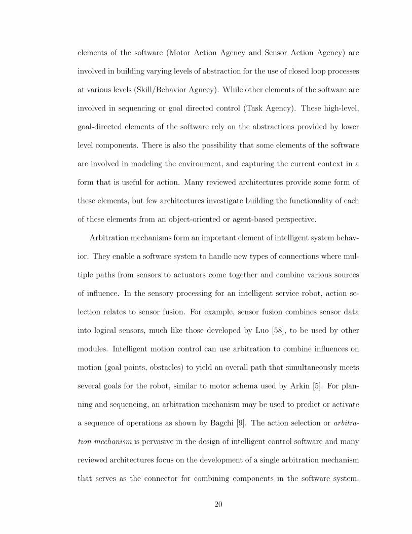
elements of the software (Motor Action Agency and Sensor Action Agency) are
involved in building varying levels of abstraction for the use of closed loop processes
at various levels (Skill/Behavior Agnecy). While other elements of the software are
involved in sequencing or goal directed control (Task Agency). These high-level,
goal-directed elements of the software rely on the abstractions provided by lower
level components. There is also the possibility that some elements of the software
are involved in modeling the environment, and capturing the current context in a
form that is useful for action. Many reviewed architectures provide some form of
these elements, but few architectures investigate building the functionality of each
of these elements from an object-oriented or agent-based perspective.
Arbitration mechanisms form an important element of intelligent system behav-
ior. They enable a software system to handle new types of connections where mul-
tiple paths from sensors to actuators come together and combine various sources
of influence. In the sensory processing for an intelligent service robot, action se-
lection relates to sensor fusion. For example, sensor fusion combines sensor data
into logical sensors, much like those developed by Luo [58], to be used by other
modules. Intelligent motion control can use arbitration to combine influences on
motion (goal points, obstacles) to yield an overall path that simultaneously meets
several goals for the robot, similar to motor schema used by Arkin [5]. For plan-
ning and sequencing, an arbitration mechanism may be used to predict or activate
a sequence of operations as shown by Bagchi [9]. The action selection or arbitra-
tion mechanism is pervasive in the design of intelligent control software and many
reviewed architectures focus on the development of a single arbitration mechanism
that serves as the connector for combining components in the software system.
20
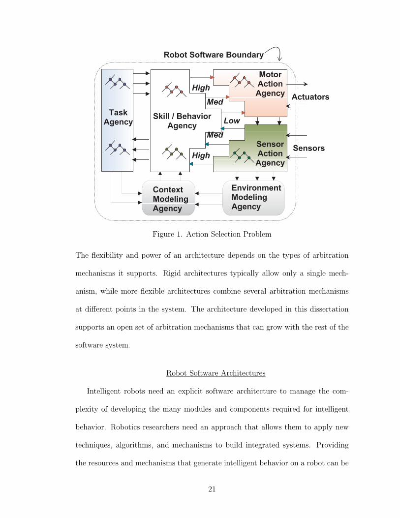
Figure 1. Action Selection Problem
The flexibility and power of an architecture depends on the types of arbitration
mechanisms it supports. Rigid architectures typically allow only a single mech-
anism, while more flexible architectures combine several arbitration mechanisms
at different points in the system. The architecture developed in this dissertation
supports an open set of arbitration mechanisms that can grow with the rest of the
software system.
Robot Software Architectures
Intelligent robots need an explicit software architecture to manage the com-
plexity of developing the many modules and components required for intelligent
behavior. Robotics researchers need an approach that allows them to apply new
techniques, algorithms, and mechanisms to build integrated systems. Providing
the resources and mechanisms that generate intelligent behavior on a robot can be
21
viewed as a complex system integration problem. One way to manage the com-
plexity of development is to adopt a software architecture that specifies possible
components and connections. The architecture specifies a system decomposition
that divides the system into simpler elements and provides integration mechanisms
for combining the simpler elements into the whole control system. Inherent in this
integration is a kind of action selection or arbitration process. What follows is a
review of architectures, each of which provides its own solutions to the architecture
problem and a discussion of various architectural features.
Knowledge-Based Architectures
Both the State Operator and Result (SOAR) architecture by Laird and Newell [54,
55] and the Adaptive Control of Thought (ACT*) approach of Anderson [4] are
examples of knowledge-based approaches to the intelligent systems problem. Some
authors call them deliberative because the declarative representation used requires
application or “deliberation” in order to generate actions. This process is usually
based on the evaluation of a knowledge base expressed in logic or a search pro-
cess [11] with heuristic evaluation of alternative situations (situation calculus) [77].
The resources, tasks, and goals in the system are all represented as knowledge, usu-
ally defined in the form of a logical language or production rules. The focus of
these approaches is the pursuit of explicitly represented goals and the aquisition,
manipulation, and application of “knowledge.” When a sufficiently restricted en-
vironment is used, these architectures excel by applying their knowledge of that
environment. The essential limitation of such architectures is that they are pre-
scriptive in nature. Every element and action must be prescribed and defined by a
22
formal set of rules. The robot must maintain a formal model of its world in order
to act within that world.
Most approaches in knowledge-based architectures are based on the physical
symbol system hypothesis described by Rich [73]. Given an appropriate world
model, these systems can solve intricate problems. The success of these architec-
tures in reasoning problems like games has given them the reputation as the best
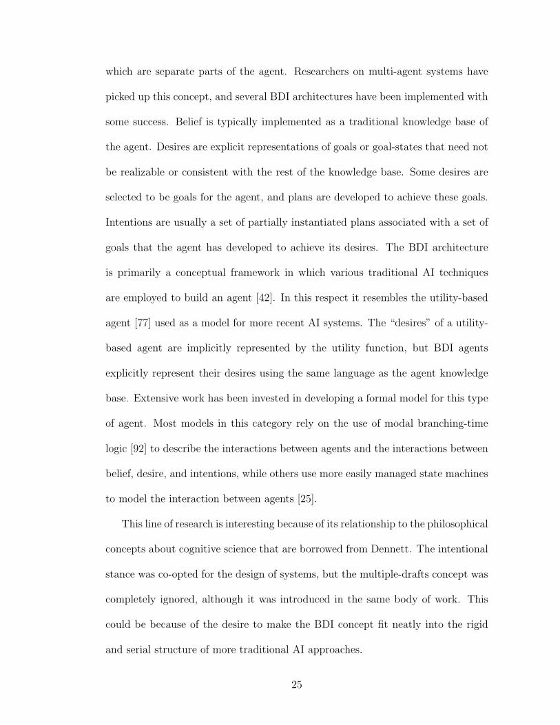
path toward general intelligence. To be useful for robots the A.I techniques must
be embedded in an architecture for the agent, and due to the monolithic nature of
the representation used in traditional approaches, a centralized “intelligent agent
structure” was devised using the sense, model, plan, act (SMPA) loop shown in
Figure 2. This approach has been used to build the control systems for robots like
Shakey [?] and has been extended to include notions from utility theory [77, 11].
These extensions resulted in a new architecture in which to apply A.I. techniques
called the utility-based agent approach, shown in Figure 3. Although it incorpo-
rates a kind of soft value judgment (utility), this new approach is also essentially
monolithic in structure and serial in processing. The important aspect to note
is that the A.I. reasoning methods are a single mechanism for selection of action
and the architecture is the structure that supports the use of this mechanism as a
robot (or other) system controller. The A.I. mechanism is very complex, but the
architecture of the software is essentially a single, serial data flow diagram.
There have been recent developments of a new type of model for knowledge-
based agents. This model was influenced by philosophical contributions of Den-
nett [29] and his psychology of the intentional stance. The concept is that some
systems are most easily described in terms of beliefs, desires, and intentions (BDI),
23
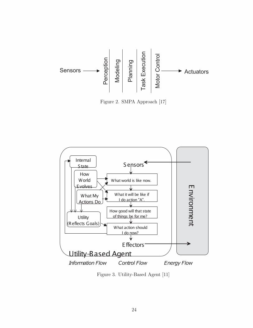
Figure 2. SMPA Approach [17]
Figure 3. Utility-Based Agent [11]
24
which are separate parts of the agent. Researchers on multi-agent systems have
picked up this concept, and several BDI architectures have been implemented with
some success. Belief is typically implemented as a traditional knowledge base of
the agent. Desires are explicit representations of goals or goal-states that need not
be realizable or consistent with the rest of the knowledge base. Some desires are
selected to be goals for the agent, and plans are developed to achieve these goals.
Intentions are usually a set of partially instantiated plans associated with a set of
goals that the agent has developed to achieve its desires. The BDI architecture
is primarily a conceptual framework in which various traditional AI techniques
are employed to build an agent [42]. In this respect it resembles the utility-based
agent [77] used as a model for more recent AI systems. The “desires” of a utility-
based agent are implicitly represented by the utility function, but BDI agents
explicitly represent their desires using the same language as the agent knowledge
base. Extensive work has been invested in developing a formal model for this type
of agent. Most models in this category rely on the use of modal branching-time
logic [92] to describe the interactions between agents and the interactions between
belief, desire, and intentions, while others use more easily managed state machines
to model the interaction between agents [25].
This line of research is interesting because of its relationship to the philosophical
concepts about cognitive science that are borrowed from Dennett. The intentional
stance was co-opted for the design of systems, but the multiple-drafts concept was
completely ignored, although it was introduced in the same body of work. This
could be because of the desire to make the BDI concept fit neatly into the rigid
and serial structure of more traditional AI approaches.
25
Rao [72] introduces a variation of the BDI architecture by showing the de-
velopment of AgentSpeak(L), an agent communication language that supports
communication between agents that are based on reasoning mechanisms. May-
field [62] evaluates another agent communication language called the Knowledge
Manipulation and Query Language, which is part of a suite of languages devel-
oped to support knowledge-based, multi-agent software systems. Both of these
architectures base communication on speech-act theory.
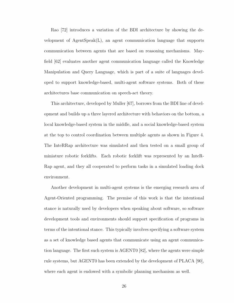
This architecture, developed by Muller [67], borrows from the BDI line of devel-
opment and builds up a three layered architecture with behaviors on the bottom, a
local knowledge-based system in the middle, and a social knowledge-based system
at the top to control coordination between multiple agents as shown in Figure 4.
The InteRRap architecture was simulated and then tested on a small group of
miniature robotic forklifts. Each robotic forklift was represented by an InteR-
Rap agent, and they all cooperated to perform tasks in a simulated loading dock
environment.
Another development in multi-agent systems is the emerging research area of
Agent-Oriented programming. The premise of this work is that the intentional
stance is naturally used by developers when speaking about software, so software
development tools and environments should support specification of programs in
terms of the intentional stance. This typically involves specifying a software system
as a set of knowledge based agents that communicate using an agent communica-
tion language. The first such system is AGENT0 [82], where the agents were simple
rule systems, but AGENT0 has been extended by the development of PLACA [90],
where each agent is endowed with a symbolic planning mechanism as well.
26

Figure 4. InteRRap Architecture [67]
27

Behavior-Based Architectures
Behavior-Based AI is a relatively new approach to intelligent control of robots
that has more in common with cybernetics than with classical AI. It was initially
developed as an example to contrast with systems that prevailed in classical arti-
ficial intelligence practice at the time. Common features in all behavior-based ap-
proaches are that the system is decomposed into behaviors, which are self-contained
control mechanisms for a robot, and the output commands from the modules are
combined through some arbitration mechanism to produce the resulting exter-
nally observable behavior of some physically situated robot. This approach frees
the designer from the need for an explicit representation of the world within a
robot. Early successes in this field have caused a reorganization of robotic ar-
chitecture development, and the once discounted reactive control mechanism has
been re-evaluated and used successfully on real robots in complex environments
by Brooks [18], Gomi [44, 43], and Ferrell [34].
The emergence of behavior-based approaches to AI that draw extensively from
biology and ethology has changed the landscape of intelligent systems architecture.
Subsumption by Brooks [17, 19], Motor Schema by Arkin [5], and the Distributed
Architecture for Mobile Navigation by Rosenblatt [75] are a few examples of archi-
tectures that combine many sources of behavior into an intelligent-acting system.
These architectures depart totally from the concept of combining “knowledge,”
which is fraught with problems of representation and search, and instead combine
the output of several behavior sources into the resulting externally observable be-
havior of a robot. The arbitration mechanism for combining the behavior varies
28

Figure 5. Behavior-Based Approach [17]
in each case, but the principle is the same. Figure 2 shows a traditional serial ap-
proach to robot control that includes the sense, model, plan, and act loop (SMPA).
Figure 5 shows the more parallel behavior-based approach. Each behavior includes
only enough modeling and processing to handle its purpose, as opposed to the
SMPA approach where the sensor data must be converted into a world model
before a decision can be made about acting.
Recently, the development of behavior-based architectures has included more
sophisticated mechanisms for action selection, especially by Maes [59], who devel-
oped fully distributed arbitration, and by Blumberg [13], who added the concept
of hierarchical composition of behavior sources. These architectures are a great
advance over the initial subsumption architecture that was based on an extremely
minimalist view of cognition and provided an intentionally over simplified archi-
tectural connection mechanism.
Very recent developments in this line of robot architecture are presented by
29
Colombetti [24]. His approach combines more formal behavior modeling with
behavior system synthesis and on-line learning of behavior. Colombetti also applies
behavior-based controllers to domains not traditionally investigated by behavior-
based AI, such as robot manipulator control.
The initial behavioral approaches all possessed a common trait: they focused on
a single combination mechanism (subsumption or fixed priority) that combined the
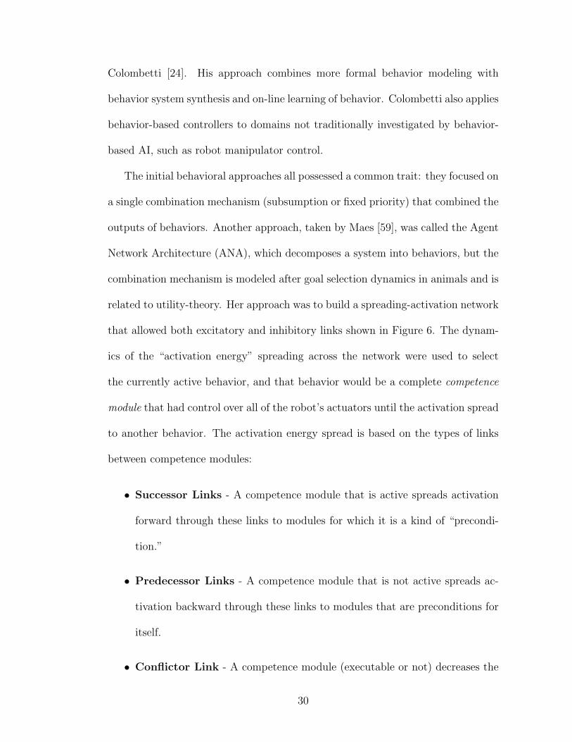
outputs of behaviors. Another approach, taken by Maes [59], was called the Agent
Network Architecture (ANA), which decomposes a system into behaviors, but the
combination mechanism is modeled after goal selection dynamics in animals and is
related to utility-theory. Her approach was to build a spreading-activation network
that allowed both excitatory and inhibitory links shown in Figure 6. The dynam-
ics of the “activation energy” spreading across the network were used to select
the currently active behavior, and that behavior would be a complete competence
module that had control over all of the robot’s actuators until the activation spread
to another behavior. The activation energy spread is based on the types of links
between competence modules:
• Successor Links - A competence module that is active spreads activation
forward through these links to modules for which it is a kind of “precondi-
tion.”
• Predecessor Links - A competence module that is not active spreads ac-
tivation backward through these links to modules that are preconditions for
itself.
• Conflictor Link - A competence module (executable or not) decreases the
30
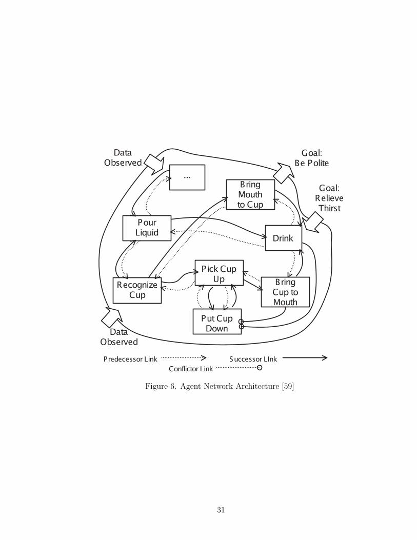
Figure 6. Agent Network Architecture [59]
31
activation of modules related to it through these links.
Activation is also generated within a competence module when it detects a
match between its preconditions and the environment; this allows environmental
conditions to affect the patterns of activation on the network. The mathematical
model used by Maes is based on a STRIPS [35] model where the environment is
described by a set of logical propositions, and each behavior or competence module
changes the set of propositions as a result of being activated. Maes provides
a mathematical model for the spreading of activation between the nodes in the
Agent Network Architecture (ANA) in [60].
Blumberg augmented the behavioral network of Maes with the concept of hi-
erarchical behavior decomposition and behavior interaction [13]. In his model,
shown in Figure 7, behaviors represented by the circles are organized into loosely
overlapping hierarchies, and at each level in the hierarchy is a group of behaviors
in competition for activation energy. Each group is denoted by the boxes sur-
rounding the behavior nodes in the network. The darker nodes have higher levels
of activation in the diagram, with the darkest nodes being the current winners at
each level. An additional feature of this approach is that the winner on each level
takes suggestions from the losers on that level into account when it takes action.
Another major improvement in this approach is that the “sub behavior” modules
can be reused by the higher level behaviors, and no signle behavior is responsible
for all actuation of the physical system. This model of behavioral decomposition
is much more practical from an implementation standpoint. The key to this model
is that activation spreads both downward and upward in the hierarchy. Activation
32

Figure 7. Blumberg’s Behavioral Architecture [13]
that spreads up represents influences of the current state of the lowest levels of the
system like sensors and actuators, while activation that spreads down comes from
the top level behaviors and can represent goals of the behavior system. Thus, the
dynamic spreading of activation results in a goal- and state-directed selection of
which behaviors to activate.
Blumberg uses a spreading activation mechanism similar to the one developed
by Maes to activate behaviors. Blumberg considers several influences on activa-
tion including releasing mechanisms (rmit), internal variables computed by each
behavior (ivit), links to other behaviors (vmt), and level of interest in a behavior
(liit).
The activation of each behavior in the network (vit) is computed using the
equations below, and the resulting activation is used to determine which behaviors
in a behavior group are activated (shown as darker colors in Figure 7):
33

vit = Max
liit · Combine
∑
k
rmki,∑j
ivjt
−
∑m
nmi · vmt
, 0
(1)
where vit is the activation value of behavior i at time t; liit is the level of interest,
and rmkt and ivjt are the values of the releasing mechanism and internal behavior
variables. The term (nmi) is a weight of connection between other behaviors in
the group. Combine is a function used to convert these parameters into a single
activation value for the behavior.
Internal variables are updated using the following equations:
ivit = (ivi(t−1) · dampi) + growthi −∑k
effectskit (2)
effectskit = (modifyGainki · vk(t−1)) (3)
Levels of interest for behavior and releasing mechanisms are updated using the
following equations:
liit = Clamp(((lii(t−1) · dampi) + growthi − (vi(t−1) · bRatei)), 0, 1) (4)
rmit = Clamp(TemporalF ilter(t, rmi(t−1), F ind(sit, dMini, dMaxi)·
Filter(sit) · Weight(sit, dOpti)),mini,maxi)
(5)
From the software architecture point of view, spreading activation represents
a very unusual way to coordinate processing modules in the system. There is
no central locus of control, and decisions are made locally by each module. The
communication between modules is extremely simple and low bandwidth; the con-
nector for spreading activation is like the software realization of a single signal
34
carrying wire between agents with little or no semantic content. Nevertheless,
these approaches provide a viable alternative to traditional architectural connec-
tions between software modules that are potentially less fragile to evolution of the
system.
AuRA [6] is a highly practical hybrid approach to robot control that focuses on
the mechanism for motor command combination. The mechanism for combining
motor commands is called motion schema and is inspired by biological models of
motor control. This architecture allows motion commands from a wide variety
of sources to contribute to robot motor control. The expressive power of motor
schemas for movement control is key to the AuRA architecture shown in Figure 8.
Motion schema are like reactive commands or reactive programs, and the schema
manager arbitrates between the active schema to compute the resulting command
using a weighted summation. Deliberative and reactive influences are combined
in AuRA by combining the resulting influences at the schema level. The original
motor schema could be interpreted in terms of a two-dimensional vector field that
influences robot motion shown in Figure 9. Motor schema are of several varieties:
• Goal Attractor - Field points toward goal at every point.
• Obstacle Repulsor - Field points away from obstacle in region around the
obstacle.
• Direction - Field is uniform at all points.
• Path Region - Field points toward a bounded region.
• Noise - Field is random at all points (Helps to avoid local minima).
35

Figure 8. AuRA Architecture [6]
Figure 9. Motion Schema Concept from Arkin [6]
36
The overall influence of the schema contributions on robot motion is computed
as a kind of weighted sum of forces of active schema, where k ranges over the
activated schema, F schemak is the contribution of schema k, and W schema
k is the
relative weight of schema k:
Ftotal =
∑k F schema
k · W schemak∑
k W schemak
(6)
Then this total force is converted to a velocity command for the robot through a
simplified damping model for each robot axis j, where F totalj is the component of
Ftotal along actuator axis j (from Cameron [22]):
V desiredj =
F totalj
dampingj
(7)
Most of the other components in the AuRA system exist to contribute schema
based on deliberative processing or reactive rules. Motor schema were recently ex-
tended by Cameron [22] to handle more degrees of freedom by assigning a pseudo-
force interpretation of the schema contributions. The schema concept was general-
ized from the original two-dimensional vector field to a full six-dimensional (both
position and orientation) force field. These enhancements allow the schema arbi-
tration mechanism to be used to combine contributions for a multi-axis system,
such as a mobile robot with a manipulator, by propagation of pseudo-forces along
the axes of the robot in a manner similar to the Newton-Euler dynamics equations
in Craig [27].
Hybrid Architectures
The success of reactive behavior-based systems prompted several groups to
adopt a hybrid approach that combines reactive mechanisms with more traditional
37

knowledge-based approaches, such as the work on integrating world knowledge with
reactivity in (AuRA) [5, 6]. Others developed the concept of using planning as a
resource for action selection instead of the mechanism of action selection [1]. An-
other approach is to have a reactive action selection mechanism and provide it with
a “future sensor” that looks ahead and contributes to the current action. These
approaches highlight the fact that previous developments in planning, modeling,
and search have a distinct place as predictors and resources that contribute to
the action selection process for intelligent robots. Many of the hybrid architec-
tures are examples of the layered system design pattern [21] applied at the system
level, where each layer provides an abstraction for the next higher layer based on
resources in a lower layer.
The RCS architecture evolved through many stages, and unlike many of the
following “hybrid” architectures that are attempts to attach a behavior-based sub-
system to an existing, centralized artificial intelligence system, RCS-1 began as
essentially a behavior-based control system. The current version of RCS, called
RCS-4, is based on a hierarchy of computation and organization. The implementa-
tion of the resulting systems takes the form of a layered system as described above
with a fixed, overall structure for each layer. In addition, the design stipulates
that all modules of all layers of the system are attached to a central knowledge
database that contains information to support the world-model-based portions of
each layer in the system. A layer from RCS-4 is depicted in Figure 10.
Each layer includes a sensory processor (SP), a world modeler (WM), a behav-
ior generator (BG) and a value judgment (VJ) module. These elements correspond
38
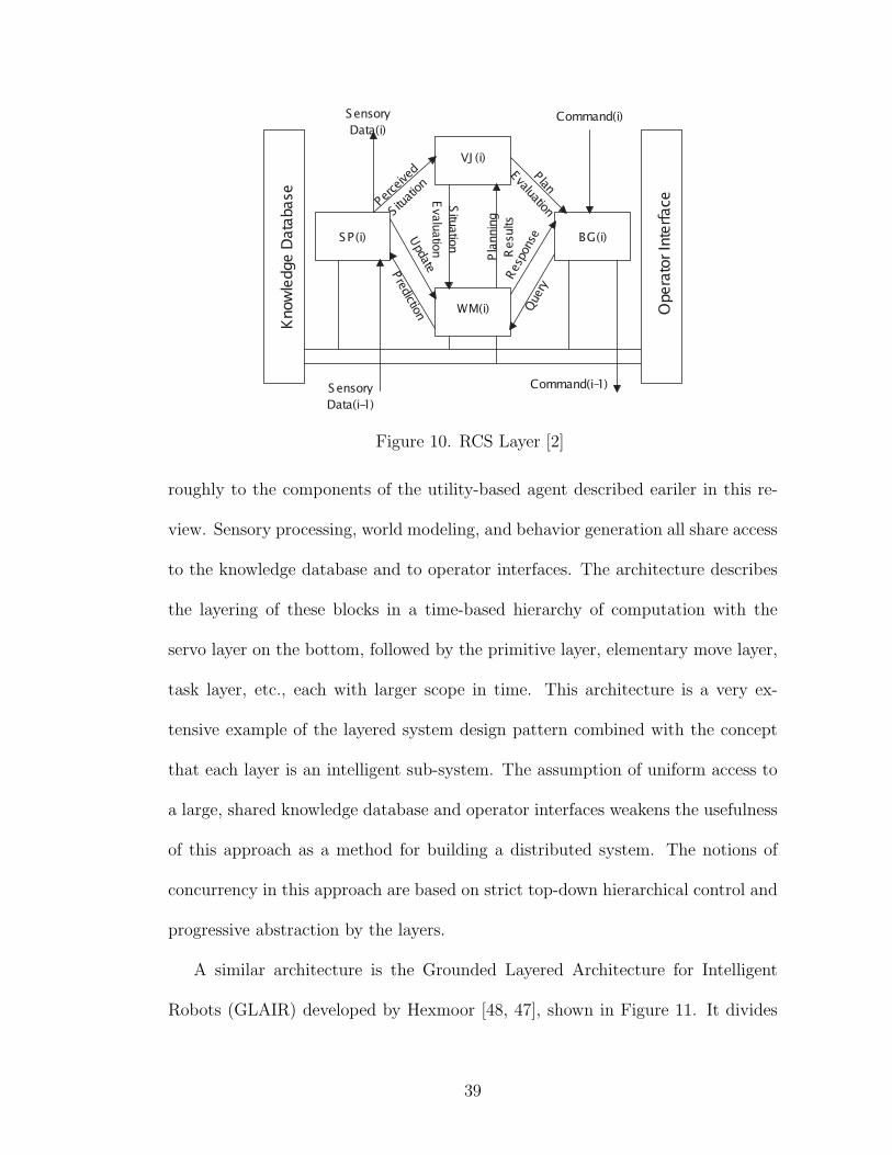
Figure 10. RCS Layer [2]
roughly to the components of the utility-based agent described eariler in this re-
view. Sensory processing, world modeling, and behavior generation all share access
to the knowledge database and to operator interfaces. The architecture describes
the layering of these blocks in a time-based hierarchy of computation with the
servo layer on the bottom, followed by the primitive layer, elementary move layer,
task layer, etc., each with larger scope in time. This architecture is a very ex-
tensive example of the layered system design pattern combined with the concept
that each layer is an intelligent sub-system. The assumption of uniform access to
a large, shared knowledge database and operator interfaces weakens the usefulness
of this approach as a method for building a distributed system. The notions of
concurrency in this approach are based on strict top-down hierarchical control and
progressive abstraction by the layers.
A similar architecture is the Grounded Layered Architecture for Intelligent
Robots (GLAIR) developed by Hexmoor [48, 47], shown in Figure 11. It divides
39
the systen into three levels, but at the bottom level the communication is similar to
that used by CIRCA. Reactive Action Packages (RAP) developed by Firby [36, 37]
embody a philosophy similar to GLAIR and CIRCA. Each RAP is a reactive sub-
program, instantiated by a higher level reasoning mechanism. The power of these
architectures is that there is a higher-level monitor for the behavior-based levels
of the system, and there is usually an accompanying specification of behaviors in
terms of pre-conditions, post-conditions, conflicts, and required collaborators that
provides a way for the higher level system to activate a “good” set of behaviors.
One way to view these approaches is that they are essentially methods of auto-
matically programming behavior-based systems. All action (observable behavior)
of the robot comes from the behavior-based layers of these systems, and the only
purpose of the higher levels is to “turn on and tune” the appropriate set of behavior
mechanisms to achieve certain goals.
Another example of the programmable reactive system is CIRCA, developed
by Musliner [68]. This approach is focused on real-time issues and is shown in
Figure 12. CIRCA consists of a reactive mechanism controlled by executing a
schedule of primitive programs created by the deliberative mechanism and sched-
uled based on knowledge of real-time deadlines and execution times of actions.
These primitive programs are called test-action pairs or TAPs and represent the
reactive program used by the reactive component of CIRCA to control its actions.
CIRCA also describes the concept of anytime algorithms, which are iterative im-
provement search algorithms that can be run as a part of a real-time system and
have the execution system specify how much time will be spent on a solution where
the quality of the solution depends on the time allotted to the algorithm. CIRCA
40

Figure 11. GLAIR Architecture [48]
41
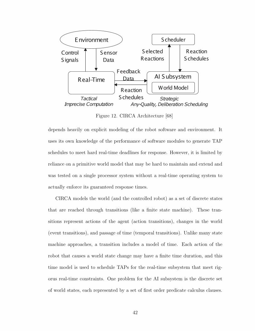
Figure 12. CIRCA Architecture [68]
depends heavily on explicit modeling of the robot software and environment. It
uses its own knowledge of the performance of software modules to generate TAP
schedules to meet hard real-time deadlines for response. However, it is limited by
reliance on a primitive world model that may be hard to maintain and extend and
was tested on a single processor system without a real-time operating system to
actually enforce its guaranteed response times.
CIRCA models the world (and the controlled robot) as a set of discrete states
that are reached through transitions (like a finite state machine). These tran-
sitions represent actions of the agent (action transitions), changes in the world
(event transitions), and passage of time (temporal transitions). Unlike many state
machine approaches, a transition includes a model of time. Each action of the
robot that causes a world state change may have a finite time duration, and this
time model is used to schedule TAPs for the real-time subsystem that meet rig-
orus real-time constraints. One problem for the AI subsystem is the discrete set
of world states, each represented by a set of first order predicate calculus clauses.
42
This representation limits what can be effectively used as a world state in the AI
subsystem. However, in restricted domains it is possible to build TAP schedules
that meet hard real-time deadlines that guarantee a certain level of performance.
From a software architecture standpoint the real time component of CIRCA is
an instance of the microkernel design pattern for software systems [21], and the
interaction between reactive and deliberative components can be viewed in terms
of the reflective design pattern [21] as well.
The artificial intelligence laboratory at SRI international developed a similar
layered approach that is based on building the low-level robot control from a set
of behavior schemas, expressed in multivalued (fuzzy) logic [79]. This approach
develops a number of interesting techniques for specifying direct control of a mobile
robot using fuzzy rules grouped into coherent units called behavior schemas. In
turn, the outputs of these behavior schemas are blended together (via a weighting
function) by the outputs of fuzzy rules used to detect context. The technique
is called context dependent blending of behavior schemas. In addition to this
reactive control system, their architecture uses a traditional planning system to
build up sets of behavior schemas and assign the blending rules, so it is also a
kind of automatic programming in the spirit of CIRCA and other hybrid, layered
architectures.
Multi-Agent Architectures
“Agent”, is employed to an extremely wide variety of things in the literature.
43

However, there are a few distinct architectural uses of the term. In object-
oriented system modeling [76] and distributed A.I. [78], the word describes an in-
dependent software module within a system that interacts with other independent
software modules to solve some problem. Some approaches use multiple agents
(multi-agent approaches) as the overall system organization, while others create
a microcosm of classical AI within a set of agents where each agent senses, mod-
els, plans, and executes using a formal reasoning mechanism. Software agents
are linked directly through message-based communication as in MIX [49] or by
blackboards (described below). Each agent can be an expert in its own domain
and work with others to cover a larger domain. These architectures suffer from
some of the same problems as traditional AI because of the need to represent the
world explicitly using a physical symbol system. There is a tacit assumption that
some universal meaning exists which enables any agent to communicate with other
agents in any type of relationship. This means that agents share semantics. While
it may be possible to develop such a language, it may not be efficient for sim-
ple relationships or too verbose and cumbersome for complex relationships. The
Knowledge Query and Manipulation Language (KQML) and the Knowledge In-
terchange Format (KIF) are two developments along this line and are described in
the context of intelligent agents by Mayfield [62] and by Wooldridge [93]. These
languages allow intelligent knowledge-based agents to interact using speech acts.
Essentially, speech acts are forms of communication that are represented as struc-
tured message passing between modules.
The concept of using interacting networks of “agents” or components to control
44

an intelligent system comes from distributed AI [78, 31]. One sketch of this multi-
agent intelligent system is found in Minsky’s Society of Mind [65], which suggests
the concept of an agent as a distinct unit of system organization as well as the
composition of agents into agencies using very simple connections. One appeal of
this approach is that it maps well to multiprocessor computational architectures
for implementation. Based on this sketch, Lim [57] developed an approach for
agent-based programming of mobile robots that did not rely on blackboard com-
munication. Agents communicate by passing messages to a set of ports on other
agents and each agent processes messages as they arrive at its ports. There is
little structuring of the messages in this architecture so the representations used
for communication may become harder to manage as the system grows. However,
the ability to hierarchically compose software modules is quite powerful in this
architecture. This power comes from the fact that it is essentially an instance of
the pipes and filters design pattern [23].
A network of software modules connected using a blackboard was developed
by Bagchi [10] for the ISAC 2 system. This system is depicted in Figure ??.
Some of the software modules in this system represent functional aspects of the
system, while others are more encapsulated, like the arm module which captures
a software model of the robot arm itself. This software system was successfully
used to develop demonstrations of an intelligent service robot system. Although
it provided very flexible operation, the blackboard caused problems because of its
centralized role in nearly all communications between modules. Furthermore, the
interaction between modules was essentially ad hoc and had no formal language.
Over time the complexity of the system grew such that the blackboard language
45
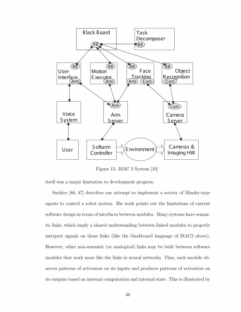
Figure 13. ISAC 2 System [10]
itself was a major limitation to development progress.
Suehiro [86, 87] describes one attempt to implement a society of Minsky-type
agents to control a robot system. His work points out the limitations of current
software design in terms of interfaces between modules. Many systems have seman-
tic links, which imply a shared understanding between linked modules to properly
interpret signals on those links (like the blackboard language of ISAC2 above).
However, other non-semantic (or analogical) links may be built between software
modules that work more like the links in neural networks. Thus, each module ob-
serves patterns of activation on its inputs and produces patterns of activation on
its outputs based on internal computation and internal state. This is illustrated by
46

Figure 14. Suehiro’s Agent Network [87]
Figure 14. However, there are no explicit “messages in a language” sent between
two agents.
Some hybrid approaches combine many complex features, like the multiple-
blackboard approach described by Beyer and Smieja [12, 84]. This approach re-
sulted in the JANUS architecture, which represents the control system for a robot
as a society of agents. This architecture is shown in Figure 15. One unique feature
of JANUS is the use of components called reagents, which stands for reflective
agents. These reflective agents contribute knowledge and commands to their con-
nected blackboards but also include a confidence measure with each contribution.
The reflective agent has a self-evaluation mechanism that allows it to adapt its
47
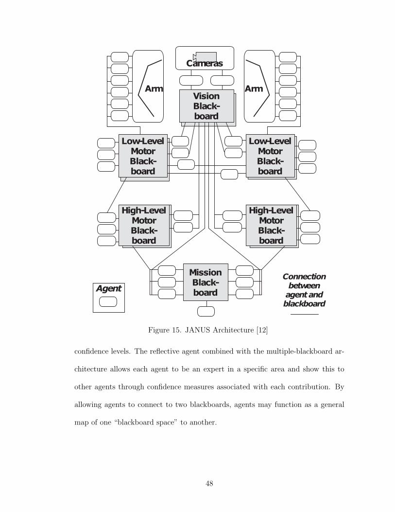
Figure 15. JANUS Architecture [12]
confidence levels. The reflective agent combined with the multiple-blackboard ar-
chitecture allows each agent to be an expert in a specific area and show this to
other agents through confidence measures associated with each contribution. By
allowing agents to connect to two blackboards, agents may function as a general
map of one “blackboard space” to another.
48

Architecture Components IntegrationANA Competence Modules Spreading ActivationSubsumption Behaviors SuppressionCIRCA Knowledge, Reactive Automatic ProgrammingJANUS Reagents Free Form (Blackboard)InteRRap Behavior, Local and Social Hierarchical ControlAuRA Knowledge, Reactive Automatic ProgrammingSMPA Knowledge ReasoningISAC2 Agents Free Form (Blackboard)MIX Agents Knowledge Exchange (Speech Acts)IMA Agents Multiple Agent Relationships
TABLE 1 Summary of Architectural Properties
Discussion of Issues
From the preceeding review if can be seen that descriptions of intelligent ma-
chine software systems from the literature frequently involve software architecture
and frequently describe their architecture in very informal terms. Some of the
reviewed systems, principally knowledge based approaches, describe software ar-
chitectures with a goal of using a fixed set of software modules and connections
to which knowledge is added that will control a robot. Other approaches, notably
behavior-based approaches, have the view of the software system gaining new struc-
ture as it is developed over time. Hybrid approaches are frequently divided into
two parts. The knowledge based part is designed to automatically program the
behavior based part in some way. Below, Table 1 shows a selected group of archi-
tectures, their primary components and methods for integration. Figure ?? is an
attempt to map out many of the reviewed architectures in terms of their derivation,
influences from other fields, and basic decomposition method.
49

Figure 16. Map of Robot Architectures
50
CHAPTER III
OVERVIEW OF THE INTELLIGENT MACHINE ARCHITECTURE
The power of intelligence stems from our vast diversity, not from any single,
perfect principle. Eventually, very few of our actions and decisions come to depend
on any single mechanism. Instead, they emerge from conflicts and negotiations
among societies of processes that constantly challenge one another.
- Marvin Minsky
Introduction
The Intelligent Machine Architecture (IMA) [71, 50] uses a two levels of ab-
straction to describe the software system for an intelligent machine. The high level
model is called the robot-environment model. This model describes the software
system in terms of a group of software agentsconected by a set of relatioships.
This agent-based decomposition helps developers manage the inherent complexity
of system integration for intelligent robots by emphasizing strong encapsulation
and reusability and by capturing interactions between system components with
an explicit representation of connections. The concepts used for this agent-based
decomposition are inspired by Minsky’s Society of Mind [65]. The architecture
also includes an implementation level model that describes each of the agents and
relationships in the high-level model as a network of software modules called com-
ponent objects. This level is called the agent-object model. A software system
built under the IMA is a system of concurrently executing software agents, formed
51
from reusable component objects, that use the computational, sensory and actu-
ator resources to perform the tasks for an intelligent machine, such as a service
robot. At the same time this network can be seen to describe a kind of model of the
robot and environment and therefore is called the robot-environment model. Each
relationship between agents encapsulates and manages the protocol of communi-
cation and usually involves an arbitration mechanism that governs the interaction
between participants. This two-level architecture addresses software engineering
issues such as reuse, extensibility, and management of complexity, as well as sys-
tem engineering issues like parallelism, scalability, reactivity, and robustness. The
IMA draws on ideas from many modern robot software architectures including the
Subsumption Architecture [19], AuRA [6], CIRCA [68], GLAIR [48], and others
and represents the synthesis of many ideas from these systems and from software
architecture research [81, 88] into an pattern for the development of software sub-
systems of intelligent machines.
The basic elements of our agent-based system architecture are agents and re-
lationships. The agent-based system forms a model and controller of the robot
system, which is implemented by a lower-level, explicit software model used to
manage development and software reuse. Thus, there are two modeling levels in
the intelligent machine architecture: the robot-environment modeling level and
the agent-object modeling level. The robot-environment modeling level describes
the robot as a set of resource, skill, behavior, task, and environmental agents that
are dynamically connected by a set of relationships. The agent is modeled as a
concurrent decision or computation process that is fed input representations and
modifies output representations through relationship protocols. The agent-object
52
level supports the assembly of these agents through combining many reusable sub-
components (state, policy, and mechanism ) and their parameters. In addition,
these sub-components can be customized with developer-supplied changes using
the code framework. Our architecture uses two levels of modeling to minimize
dependence on particular internal representations. Thus, a particular model of a
particular task or type of robot is not a part of the architecture; it is part of an
application developed within the architecture. We also employ modeling of each
agent as an individual, independent software system to facilitate component reuse
in our development process and provide the potential for tools to be developed to
automatically modify system structure and generate new agents.
In continunally improved systems, such as a research service robots, it can be
impossible to formally validate the design of the system. Validation can be expen-
sive in terms of development time so it is proposed that at the architectural level,
monitoring should be used to ensure proper operation. Monitoring introduces lit-
tle overhead and is robust to rapid development of the system. The monitoring
properties need to be specified only once, and if testing of the system yields mon-
itoring errors, then developers have a detailed error log to guide improvements.
Monitoring is also applicable to environments where there is run-time adaptation
and reconfiguration, whereas using formal verification in an evolving system may
be costly in terms of performance.
It is interesting to note that robustness of operation to environmental changes
is also closely related to robustness of the robot software to evolutionary design.
The loosely coupled network of agents is insensitive to changes in the software
implementation because the level model of the system controls the overall structure
53

but makes fewer commitments about specific mechanisms or algorithms used to
evaluate intputs and compute outputs. The high level model provides a shell
around the implementation level model that isolates the integration of the system
from changes and improvements within a single agent. The isolation between these
models also allows individual agents to select and use different mechanisms as the
environment changes, but still keep the overall structure of the software system
intact.
The IMA supports the construction, reuse, and configuration of networked
agent systems that capture the robot and its environment. Encapsulation scope
at runtime is not the same as encapsulation scope at design/configuration time.
For example, modules of nearly any type may be incorporated, and multiple com-
position mechanisms (aspects) can be described at run-time and at design time.
At run-time the dynamic configurability provides a degree of fault-tolerance while
allowing an iterative, experimental development style that is advantageous for ex-
ploratory software system development [19]. A diagram of related development
processes using IMA is shown in Figure 17.
Each agent is based on a single element of the domain-level system descrip-
tion and tightly encapsulates all aspects of that element, much like the concept
of object in object-oriented systems. The agent serves as a scaffolding for ev-
erything the software system knows or does relating to an element of the robot,
tasks or environment. For example, Figure 18 shows that IMA agents are built
to represent the physical resources of the robot (e.g., Arms, Pan-Tilt Head, Image
Capture, Sound Capture, Speech I/O, Sonar, Lidar, etc.) as well as behaviors
(e.g., Avoid Collisions, Coordinate Movements, Emergency Reflexes), skills (e.g.,
54

Figure 17. IMA Development Process
55
Visual Tracking, Grasping, Visual Servoing), and tasks (e.g., Feed Soup, Find Ob-
ject, Assemble Parts). However, the model of the environment is also developed
as a set of agents that share the robot’s physical resources (e.g., Bowls, Blocks,
Parts, Walls, Places, Forks, Collections) and engage in a process of anchoring [79]
to keep their state coherent with the world as experienced by the robot’s sensor
resources. Any system that captures elements of the environment in a model would
engage in such a process, and the environment agents in IMA are a distributed,
parallel embodiment of that process of “actively modeling” the environment. An-
other software agent represents the user of the system. This user agent uses the
resources of the robot to estimate the state of the user and represents what the
system knows about the user. One feature of this loosely coupled system design
is that the agent-based decomposition facilitates parallel processing and can take
advantage of both distributed and SMP computer systems more effectively than
monolithic architectures to handle larger systems, if communication is controlled
properly. Finally, each agent acts locally based on internal state and provides a
set of services to other agents through various relationships.
Robot-Environment Model
In the terms used by Rumbaugh [76], IMA agents are like actors (they use
other agents as resources, have a thread of execution) and servers (they provide
resources for other agents as well). The agent-based decomposition of the system
is a generic idea; however, the robotics domain suggests a classification scheme for
IMA agents that conceptually divides the system into several rough layers based
on the types of relationships they support and what they model in the system.
56

Figure 18. Correspondence of IMA Agents to System-Level Entities
In a relationship between agents, one agent provides another agent with re-
sources for action. This model of action and communication requires a different
view of system design and is more loosely coupled than traditional software ap-
proaches. One justification for this tradeoff is the time value of information in
robotic systems. Unless some information in the software system can become a
resource for action, it rapidly becomes useless for the robot to retain, process, or
evaluate the information.
Agents
An Agent within the IMA approach is assumed to have certain properties that
separate it from the typical uses of the term “Agent” and focus on what is es-
sential to being an agent. Some authors stipulate that agents must be able to
57
reason, hold explicitly represented beliefs, and maximize utility [92, 72, 38], but
that is not essential to the usefulness of the agent concept as an abstraction for
the development of software systems [8, 69, 61].
• Autonomy - Agents own their sub-components. They are separate and dis-
tinct concepts in the domain for which the software is written. Thus, they
have an inside and an outside that are necessary for strong conceptual en-
capsulation at the system level and support interaction through well-defined
ports called relationships and links. An agent might be viewed as an active
subsystem in the overall software system.
• Proactivity - Agents act locally, based on their own internal state, resources,
and observations of other agents through specific relationships. The core of
the agent’s operation is a decision or action selection process that may take
the form of a state machine or other computational process that maps inputs
and local state to updates of outputs.
• Reactivity - Agents are reactive because they respond to changes in their ex-
ternal environment. The agent operates in a continual loop, checking condi-
tions, running computations, and updating outputs, so changes are detected
and appropriate actions can be selected.
• Connectivity - Agents are connected to each other because they model only
a single concept and need services provided by other agents to make a com-
plete system. The connections between agents can be simple data flows,
or more complex relationships. Complex connections support arbitration be-
tween connected agents and are used to model interactions that communicate
58
commands or internal state values from other agents.
• Resource Limits - Any real system is resource limited, however there needs to
be some way to express this in the software system that allows the software
system to adjust operation based on resource usage. Therefore relationships
between agents have several aspects. The primary aspects deal with commu-
nicating information between the agents, while other aspects associate some
state of the agent with resources. These other aspects can form the input for
an arbitration process that selectively updates or incorporates information
of other agents in the relationship, thus respecting resource limits during in-
teraction. Internally, an agent’s action selection process can use an element
of the agent’s state to vary it’s choice of computations to consume more or
less computational resources.
Another important aspect of IMA is the loosely coupled, asynchronous op-
eration of the agents in the system. By using the abstraction of asynchronous,
decision-making agents, it is possible to simplify the system model at a high level.
There is often a great temptation to over-specify the higher levels of a system that
lead to very brittle operation. The collection of asynchronously executing agents
provides an abstraction that eliminates many concerns about synchronization, be-
cause the architecture provides each agent with a knowledge of time that allows
each local decision process to evaluate information based on its age relative to
that agent. The agents in IMA work much more like a group of control loops,
that traditional software systems; continually sampling inputs, updating states
and computing new outputs.
59

Relationships
One novel aspect of IMA is the explicit use of a set of architectural connectors
called agent relationships. These relationships capture interaction between agents
that includes both typical software interactions (like function signatures, sequences
of method calls, etc.) as well as less structured interactions (like spreading acti-
vation, or motion schema for example). By building a system from these multi-
aspect connectors, it is possible to combine reusable resource limiting mechanisms
and take advantage of the use of more explicit interaction as well. The relation-
ships between agents are implemented as sets of reusable component objects that
are aggregated within a controlling agent, allowing that agent to participate in a
given relationship. This allows each relationship to be implemented once and be
configured and reused throughout the network of agents.
An IMA relationship supports structured communication between the partic-
ipants in that relationship and usually provides an arbitration mechanism that
is suited to the particular relationship. The idea of relationship in IMA is that
it is a high-level connector between the high level components of the software
system. In previous architectures for robots, many designs have offered only a
single connector type (e.g., Signal Subsumption in the Subsumption Architecture
or Spreading Activation in the Agent Network Architecture). Some examples of
complex relationships and the associated arbitration mechanisms are as follows:
• Actuator Arbitration - Pseudo impedance models, extension of Cameron [22,
69].
60

• Sensory Arbitration - Voting schemes, activation maps, consensus mech-
anisms as in Luo [58].
• Goal Arbitration - Spreading activation from Bagchi [9] and Maes [59].
• Context Arbitration - Spreading activation from Anderson [4].
In IMA, the agent is a container for services that shields the overall system
from changes in the implementations and mechanisms that make up the services
provided. By splitting the overall design into two levels, it is possible to evolve one
level (improve the algorithms and mechanisms within an agent) without affecting
the other level (overall agent network). It is also possible to add new connectors
(relationships) to the architecture within minimal impact on older parts of the
system.
Agent-Object Model
The IMA Agent is a concurrently executing, potentially goal-seeking software
component that is equipped with links to other agents, called relationships. Each
agent contains at least one thread of execution, a set of relationships to other
agents, and perhaps access to hardware of the system. The agent also contains
a number of representations that are used for internal computation or to denote
the state of a relationship to other agents. In general the agent is an autonomus
decision-making software module. It takes all of the accumulated state that is
available internally and locally (from relationships and other links) and makes
a decision to perform certain actions based on this locally available information.
These actions can include hardware output (if the agent is connected to hardware),
61
computation, or communication with other agents.
What follows is an introduction to the model of an IMA Agent itself. This
is the model used to build agents from reusable component obejcts. This model
permits explicit representation of software configuration and on-line modification
of the agent system and individual agents. The IMA divides the model of robot
control software into four components that capture four primary aspects of the
agent system design problem:
• Agents - Concurrency, scoping, and decision-making; decision objects.
• Relationships - Interaction protocols, connection ports; protocol objects.
• Representations - Communication, complex information, encapsulation;
state objects.
• Activities and Actions - Algorithms, computations, decision processes;
functional objects.
The agent model also relies on reusable sets of component-objects to facilitate
growth of the system over time. By building software using this model, developers
of the system focus on modeling distinct concepts and providing services relevant
to the robot control system instead of becoming the “algorithm in a box” that is
typical of many functional-modular software systemss. The IMA uses algorithms,
representaitons, and links between agents as component-objects within each agent,
and each of these elements can be reused in many agents, in varied configurations
or for completely different purposes at the same time. For example, a new object
classification algorithm is developed as a component object. Then, by editing a few
62
decision rules in each agent, this new method for recognition can be used by many
different elements of the system. No new “module” must be built and interfaced to
the system to provide this algorithmic service; the integration happens at a much
finer-grained level that is conceptually appropriate in the context of the evolving
robot control system. As shown in Figure 19, agents are built from a standard
set of components that follow current design patterns for object-oriented system
design, including:
• Agent Manager - Provides the scaffolding on which other pieces of the agent
are built, as well as features such as persistence. This element also provides
a meta-level interface through which another agent can inspect its own com-
position and perhaps alter it if necessary. This feature is currently intended
to be used to support on-line interactive tools for agent construction and
tuning, but it could be used in other ways.
• Agent Engine and Activities - The engine provides the central action selection
process for an individual agent and invokes other agent components. Activ-
ities are other, concurrent processes within the agent. These can be used
as background processing or to separate deliberative processes and reactive
processes within an agent to assign different priority levels. The engine and
other activities are based on a concurrent finite state machine model [46].
Like any other part of an agent, The engine and activities are replaceable
components that can be upgraded or altered to address the needs of specific
agents within a growing system. The current engine can support a hierar-
chical state machine for agent action selection.
63
• Agent Representations - These components are a kind of generalized produc-
tion for the agent that includes the evaluation of agent components, as well
as an invocation mechanism for performing computations, assignments, and
state updates.
• Agent Resources - These elements of the agents are data repositories, al-
gorithms, tools, and links to the state of other agents. These elements are
evaluated, invoked, and updated by the invocation of mechanisms within the
agent. Components can be simple or composite component objects. Some
components might provide a kind of scratchpad or internal workspace for the
decision engine and other components, while other components are algorith-
mic resources that allow the agent to invoke highly efficient and optimized
computations in a particular situation.
• Agent Component Managers - These elements are wrappers for the agent
components that handle object persistence and provide visual interfaces to
the components that are used by developers to build up the agent systems
more easily. Component managers also provide a place for knowledge about
system properties to be stored. Thus, the component managers can be used
to implement design rules to prevent a component from being misused within
an agent. This is a kind of metadata about the component.
• Relatioship Components - These elements encapsulate the connections be-
tween agents in the system. They range from simple data flow to complex
multi-way data flows with arbitration mechanisms. The important aspect is
64

that such interactions are encapsulated in a set of components that help iso-
late agents from changes and details of the implementation of relationships
between agents.
All intelligent behavior results from the local decision process. The decision
process is not merely a condition/response sequence; it may include computation
as well. For example, it may utilize a transformation or time-varying mapping
with memory. The IMA framework focuses on managing the control state, deci-
sion process, and data state for agents by using the agent-object model to describe
the composition of the agent in terms of interacting component objects. The in-
teractions at the component object level are specified as method calls on interfaces
between components. IMA lets certain aspects of the decision process be encapsu-
lated and reused and totally encapsulates and reuses the framework used to link a
set of distributed decision processes.
Many of the core operations, such as event times, are benchmarked at run-time,
saved with the system state, and are logged to files for each agent. This provides the
system designer with a run-time assessment that monitors real-time performance to
use in decisions, update computations, updates, and actions. Instead of modeling
abstract computation for verification, this architecture benchmarks itself while
running and provides monitoring as an alternative.
Code Development Framework
The abstract concepts presented in this chapter are intended as a conceptual
guide to developing agents in IMA. These concepts encourage developers to think
in terms of developing larger-scale, more reusable, elements of the system (IMA
65

Figure 19. IMA Agent Internal Structure
66
Components) instead of plain algorithms or traditional monolithic programs. The
abstractions of representation, mechanism, and policy encourage a disciplined and
modular style of development that accomodates changes more easily by reduc-
ing or eliminating “hidden” interactions between components and forcing these
interactions out into explicit consideration.
However, an architecture is useless if developers are not encouraged to use
it and it does not help them work more rapidly or improve their development
process in some way. This is why the development of IMA is accompanied by the
development of a code framework (a set of base classes in C++) that reduce the
effort needed for developers to follow the constraints of the architecture. These
base classes provide a starting point and easy access to the agent-object model
from a more traditional programming language. Thus, a base class available for
each of the agent components that implements much of the common functionality
required:
• IMA Component- This is the generic base class for all agent components and
provides minimal naming, persistence, and component linking features.
• Mechanism- This base class adds the mechanism invocation interface and
provides a standardized way to invoke this component as a mechanism.
• Representation- This base class adds proxy and source functionality and in-
terfaces that support remote, multicast communication between source and
proxy representations. This class encapsulates one method of communica-
tion between representations. Additional mechanisms are possible because
communication is encapsulated at this level.
67
• Policy- This base class has an active thread scheduled by the underlying
operating system. These objects provide sequencing and decision-making for
the agent. They invoke various other mechanisms in the agent based on their
state and the state of other agent components.
• Agent Manager- This class provides a basic implementation of the agent
timing service, persistence management, and agent event dispatching for the
other components within an agent. It also serves as the bridge between the
agent components and the outside world because it handles interactions with
the agent locator service and the agent shell.
These base-classes are described in further detail in an appendix for those
interested in the implementation details and interfaces involved in creating the
abstraction of the agent-object model.
68
CHAPTER IV
ROBOT-ENVIRONMENT MODEL IN THE IMA
Introduction
IMA is based on the concept of software as a multi-agent system that models
the robot, task, and environment. The multi-agent network controls the robot and
is a model for the robot system at the same time. This structure is augmented
by a lower-level model for implementing agents from component-object software.
Thus, there is an implementation relationship between the distributed agent-level
abstraction of the system and the component object network.
IMA uses a network of software-agents to represent the control software for a
robot system, plus the same network is a model for the robot system and envi-
ronment. This model is based on object-oriented models that favor strong encap-
sulation of modeled entities and explicit relationships between modeled entities.
IMA supports a kind of self modeling design that reflects the structure of the robot
system and environment in the software itself.
In even the simplest monolithic robot systems, certain aspects of the robot
and environment are reflected in the software structure. However, “models of the
environment” are usually treated as passive data that are manipulated by a fixed
algorithmic mechanism. It may be useful to go beyond this approach by incorpo-
rating ideas from object-oriented modeling that suggest building an agent-based
system that enforces strong encapsulation. As the system grows, the model grows
as well; each agent may add new information, as well as new methods for dealing
with these pieces, to the model, and new relationships may add new interactions
69
to the model. The IMA Robot-Environment model is a model of which particular
instances are controllers of a particular robot system. What is gained with this
approach is that the resulting systems may be evolved by adding new agents and
relationships along with the policies and mechanisms needed to capitalize on the
new capability, with less chance of compromising the functioning of the result-
ing system. The system-level model is a pattern for building an active model of
the robot and its environment from entities called agents and relationships. The
agent-level model, described in the next chapter, shows how to build agents and
relationships from sets of distributed component-objects.
The primary elements in the robot-environment model are agents and relation-
ships. These are the “components and connectors” of the architecture at this level
of abstraction. These components and connectors will in turn be described by
networks of component objects that implement the high-level agent model as a
lower-level concurrent, distributed object system.
IMA Agents
The agent concept forms the basis for a model of robot software that is flexible
in structure and grows over time. An agent in IMA is a software abstraction for
some element of the overall robot system. Agents are independent, asynchronously
executing software modules that communicate with other such modules using agent
relationships. The concept of agent in IMA is also related closely to the concept
of object from object-oriented programming. Agents represent independent loci of
computation and decision in the system and may have access to hardware interfaces
of the robot.
70
Intelligent Service Robot Domain Agents
A classifiation of IMA agents is described by Figure 20, which shows how one
level of the agent network depends on lower levels of the network, like the rings
in an operating system. The following classification scheme is intended to show
how an agent network might be used to model a robot system and is not a specific
“rule” of IMA design. However, IMA was designed with the intent of supporting
implementation of agent systems as described below. It is intended to help a reader
understand what agents might be used to model, based on common terminology
from other robot architectures.
The higher levels of the robot control system are task agents, skill agents, and
several types of behavior agents. Task agents are responsible for decomposing high-
level tasks into subtasks and sequencing the application of skills and activation of
behaviors. Environment agents form an active internal model of things external
to the robot. The environment agents provide a model of physical objects, robot
users, and the robot’s environment that is accessible to other agents. Skill and
behavior agents are built by combining several lower-level resource agents and a
feedback mechanism to achieve coordinated action. Behaviors include continuously
operating collision avoidance and reflexes for safety and limits, while skills include
visual tracking, grasping, manipulating objects, and navigating. The network of
skills and behaviors is not flat and may include composite skills and behaviors
that represent a sequence or collection of simultaneously active sub-units. Thus, a
composite skill is illustrated by visual servoing which includes simultaneous track-
ing (a low level skill) and directional manipulator control (another low level skill).
The inner agents in Figure 20 are most closely related to the robot hardware and
71

provide an agent-based abstraction of the robot hardware to higher layers. The
inner layers are divided into actuator resource agents, which model transfer of en-
ergy from the robot to the environment, and sensory resource agents, which model
sensing or energy transfer from the environment to the robot. The interactions
and arbitration mechanisms at this level of the system normally support both
motor action arbitration and sensor action arbitration. Motor action arbitration
combines influences from the skills and behaviors of the system into the resulting
motor actions of a robot mechanism, and sensor action arbitration combines influ-
ences from many source agents into a resulting sensor action that influences the
behaviors and goals of the system.
Conceptual Agent Interaction Model
An asynchronous model for decision, computation, and contribution is depicted
in Figure 21. Each evaluates the data it has available in a decision process, executes
come computational mechanisms based on this decision and then sends updates
to other agents. This is the conceptual model for the central activity in of each
agent and how updates and computations lead to different types of latency as
information travels between agents in the agent network.
I am aware that this subsection needs more description.
The asynchronous operation of the agents can be an advantage for the system,
if certain criteria are met by the relationships used to link agents. By adopting
this model there is the potential that significant amounts of computation and com-
munication will be wasted. However, there is a compensating mechanism in the
relationships between agents. Relationships update and use only a subset of the
72
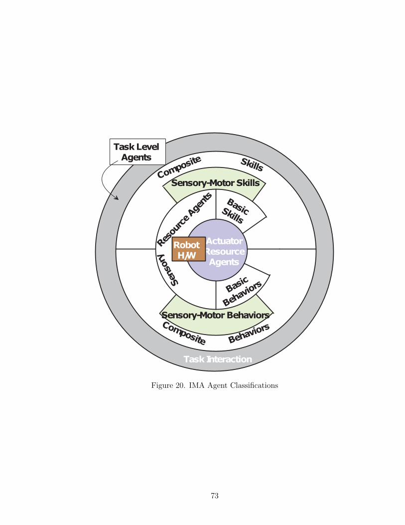
Figure 20. IMA Agent Classifications
73
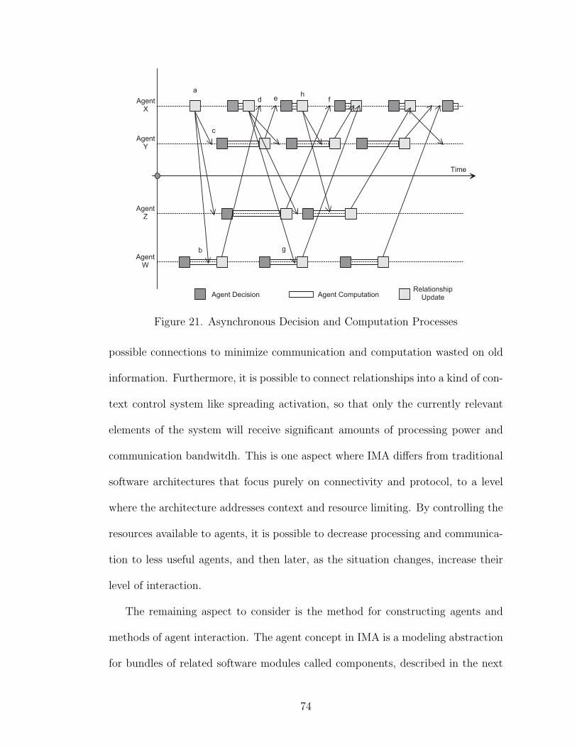
Figure 21. Asynchronous Decision and Computation Processes
possible connections to minimize communication and computation wasted on old
information. Furthermore, it is possible to connect relationships into a kind of con-
text control system like spreading activation, so that only the currently relevant
elements of the system will receive significant amounts of processing power and
communication bandwitdh. This is one aspect where IMA differs from traditional
software architectures that focus purely on connectivity and protocol, to a level
where the architecture addresses context and resource limiting. By controlling the
resources available to agents, it is possible to decrease processing and communica-
tion to less useful agents, and then later, as the situation changes, increase their
level of interaction.
The remaining aspect to consider is the method for constructing agents and
methods of agent interaction. The agent concept in IMA is a modeling abstraction
for bundles of related software modules called components, described in the next
74
chapter, while interactions between agents are introduced below.
IMA Relationships
Every relationship between agents represents explicit communication path be-
tween the agents that follows a specific protocol. This link encapsulates not only
interface signature (methods, arguments, data types) but also carries the protocol
required (sequence of function calls, exchange of messages, etc.) needed to make a
logically correct connection based on the roles of participants in the relationship.
Thus, each agent may participate in many relationships and in various roles in
each relationship. One example of a relationship might be message-passing link
between agents. These are often described in multi-agent systems that are based
on speech-act theory. The protocol for this type of link is trivial, and there are
only two possible roles: sender and receiver. This type of link depends heavily
on shared semantics between components (i.e., the receiver can understand the
language and meaning used by the sender). This dependence can be a weakness
in system development, while the totally flexible structure of message-passing is
an advantage of this kind of architectural connection. It is straightforward to get
every module in the system connected using messages, but very difficult to keep
this shared language under control as the system grows. The ISAC2 system suf-
fered from this limitation [10]. Another example of a relationship is spreading
activation. This relationship also has a simple update protocol and also has very
little semantic content because only a single number is passed between agents. The
meaning of the activation level is determined locally by the response of each agent
to changes in activation levels.
75
The types of interactions that are common in typical robot software rely on
semantic connections. These are connections between software modules that share
an explicit or (more dangerous for system growth) implicit semantics for the signals
that pass between the agents. These types of interactions are like “speech acts”
described by many multi-agent system researchers. This is an attempt to formalize
the concept of communication as just another action that an agent may select. The
pinnacle of such architectures is the BDI agent model. The shared semantics of
the language used by communicating agents defines the meaning of the signals
that pass between agents. Other types of systems rely less on shared-semantic
connections. In these systems the connections are signals that travel between
elements of the system, and each element of the system has a local interpretation
of these signals (i.e., each element has its own local semantics). This is how
computer hardware systems work. Agents connected like this are described by
Minsky, and some limited implementation was attempted by Suehiro [87]. This
kind of non-semantic connection is exploited in spreading activation systems, as
well as in behavior-based systems. The “escape” from semantics is one source of
the power of these architectures but results in a system that works much more like
a nonlinear dynamic system than a traditional software system.
The message passing (speech act) model of communication between agents
captures the procedure for sending messages as an explicit part of the model.
Object-oriented software can be viewed as a specialization of this type of message
passing where there is a special shared semantics. In object-oriented programming
there is an implied reference in all messages. Thus, when an object gets a message,
there is an implied “you” in the message allowing the sender to only specify what
76
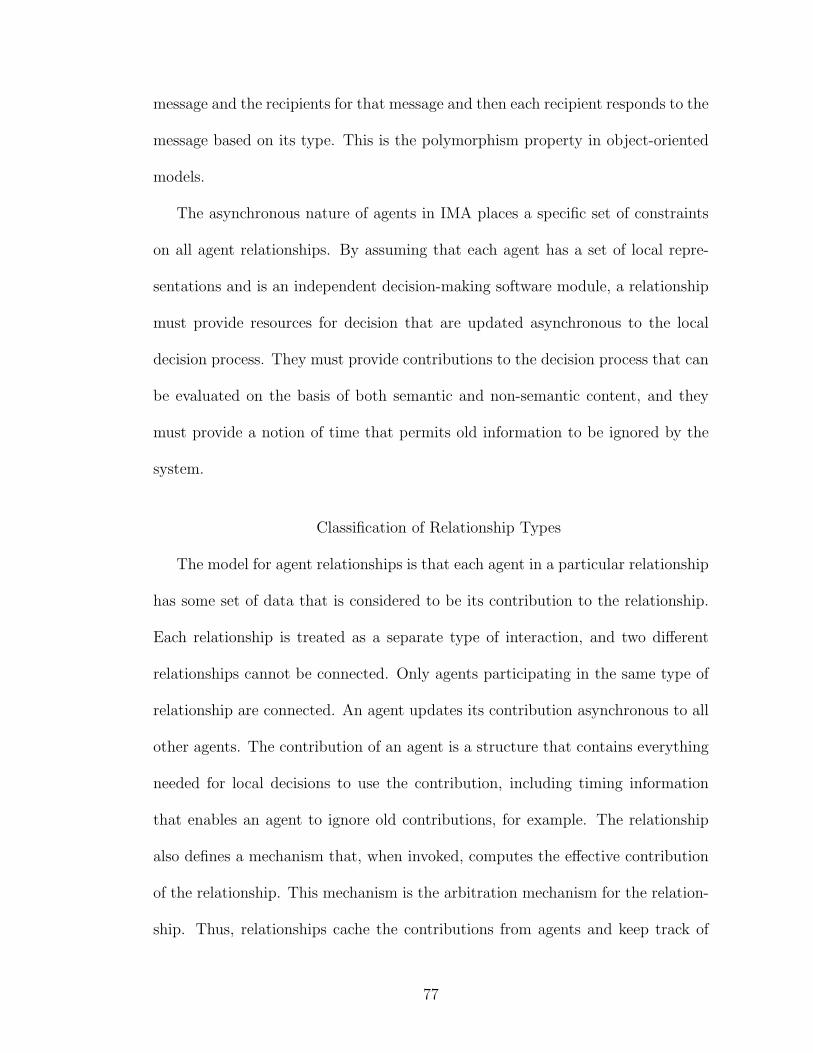
message and the recipients for that message and then each recipient responds to the
message based on its type. This is the polymorphism property in object-oriented
models.
The asynchronous nature of agents in IMA places a specific set of constraints
on all agent relationships. By assuming that each agent has a set of local repre-
sentations and is an independent decision-making software module, a relationship
must provide resources for decision that are updated asynchronous to the local
decision process. They must provide contributions to the decision process that can
be evaluated on the basis of both semantic and non-semantic content, and they
must provide a notion of time that permits old information to be ignored by the
system.
Classification of Relationship Types
The model for agent relationships is that each agent in a particular relationship
has some set of data that is considered to be its contribution to the relationship.
Each relationship is treated as a separate type of interaction, and two different
relationships cannot be connected. Only agents participating in the same type of
relationship are connected. An agent updates its contribution asynchronous to all
other agents. The contribution of an agent is a structure that contains everything
needed for local decisions to use the contribution, including timing information
that enables an agent to ignore old contributions, for example. The relationship
also defines a mechanism that, when invoked, computes the effective contribution
of the relationship. This mechanism is the arbitration mechanism for the relation-
ship. Thus, relationships cache the contributions from agents and keep track of
77

timing so that the cache may be evaluated based on age. Periodically an arbitration
mechanism is invoked to evaluate the current set of contributions and provide some
type of “effective contribution” for the relationship. Furthermore, contributions to
relationships may affect which participants receive updates when the state of the
relationship is updated by other agents. There are two broad classes of relation-
ships in IMA. Asymmetric relationships, shown in Figure 22, are typical of agents
involved in motion control or sensor fusion. Symmetric relationships, shown in
Figure 23, are typical of agents involved in sequencing, attention control, or other
higher-level aspects of robot control. The primary difference is how the arbitration
mechanism is used. In asymmetric agents, only the agent on the “receiving end”
of the relationship uses the arbitration mechanism to combine contributions (e.g.,
motion schema), while in symmetric relationships, many agents use the arbitration
mechanism to combine contributions (e.g., spreading activation). These figures are
intended to show that the relationship is treated as a component of each agent,
and hides some of the details of module interconnection between the agents.
78
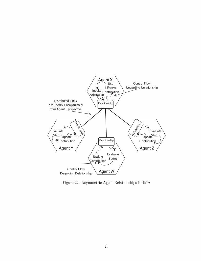
Figure 22. Asymmetric Agent Relationships in IMA
79
Figure 23. Symmetric Agent Relationships in IMA
80
CHAPTER V
AGENT-OBJECT MODEL IN THE IMA
Introduction
This level of the model describes how an agent is built from a collection of
component objects. Strong encapsulation and separation of policy, mechanism,
and representation are sought in this model. The goal of such separation is to
make the development process of agents more structured and facilitate the reuse
of software components.
Each agent in an IMA system is a persistent collection of connected objects of
the following classes:
• Agent Components - Agent components are component objects that support
a set of interfaces for management by the agent manager as well as inter-
faces for persistence to streams (blocks of bytes) and storages (hierarchical
databases of named streams). The agent component generally also supports
an external interface that exposes its specific functionality. Representations,
Relationships and Policy components are all sub-classes of agent components.
• Agent Managers - Each agent has only one agent manager. This object
supports a set of interfaces to establish local connectivity as well as establish
a high-resolution local clock and locate other agents in the system. The
agent manager is also responsible for handling the process of loading and
initializing the connections between other agent components.
• Component Links - Each agent component may define a set of outgoing
81
ports called component links. These ports are references to other compo-
nents within the agent that are automatically managed by the framework.
Component links use the agent manger to help locate their targets by name
and are automatically restored when an agent is loaded from persistent stor-
age.
• Activity and State Components - These components give the agent its inter-
nal activity and control its response to events and the results of computation.
The activity component is an object that encapsulates an operating system
thread (i.e., it is scheduled for execution by the underlying operating system)
and provides an explicit representation of the control-state within an agent.
The partner to the activity component is the state component. Each activity
may have many states, and a state may contain many concurrent activities
or states. Thus, this forms a hierarchical model of the control state of an
agent that is explicitly represented by component objects that are part of
the agent structure.
• Representation and Mechanism Components - Representation components
are the foundation of communication between agents. A representation com-
ponent is a distributed component object that supports multi-cast of its
state to a set of proxy objects in other agents. Through the representation,
multi-cast mechanism agents can observe certain peices of the state of other
agents.
• Component Managers - Component managers are an extension of the soft-
ware to permit interconnection with standard OLE and ActiveX software
82

technologies, used to build multi-media documents and other document-
centered software on the PC platform. Component managers provide a view
of a single agent component when inserted into an OLE or ActiveX con-
tainer.h Component managers allow the components of agents to be visu-
alized using graphical editors and support rendering of graphical or textual
representations into web pages containing an ActiveX component manager.
This concept is an example of the bridge design pattern [23] used to connect
two separate systems and the component managers are the bridge compo-
nents: they support some custom IMA interfaces and some standard OLE
and ActiveX interfaces.
• Relationships and Links - The connections between agents are also repre-
sented as components that are the endpoints of those connections in each
agent. Several types of links between agents are supported, from simple data
flow to full IMA relationships with arbitration mechanisms to selectively up-
date and use contributions from each participant. These components provide
a local view of the relationship between agents to all the other components
within the agent. Through polymorphism of component objects, relation-
ship and link components will be used like mechanisms or representations by
other agent components.
One of the ideas in this object model is to separate three aspects of the agent’s
operation into components that represent a concrete realization of the software
aspects of structure (Figure 24), functionalty (Figure 25) and policy (Figure 26).
Any program has these aspects, but frequently they are mingled or weaved together
83

in lines of source code. By separating these aspects it is possible to develop more
structured and reusable software a a relatively fine-grained level. These aspects
address connectivity, data flow, and control flow as separate views of the software
system. The following figures show the different aspects and which components
are involved in representing that aspect withing an agent.
The structural aspect of the agent has two different concepts. Figure 24 shows
that the agent is organized as a tree of component objects originating with the
agent manager object as the root. This structure is efficient for grouping and col-
lecting the various components within the agent as well as for storing the compo-
nents to persistent storage. Another type of connection between agent components
is supported as well. This type of connection is called the component link. Com-
ponent links complement the explicit, strongly typed incoming interfaces provided
by component objects, by adding support for strongly typed outgoing interface
connections. Thus, each agent component is designed to support a set of incoming
interfaces and explicitly connect to a set of other interfaces on other components.
These agent links are managed automatically by the framework and are a kind of
interface-connection architecture as described by Shaw [81].
The relationship between agents is represented as a set of components that are
“endpoints” of the relationship in each agent. These components encapsulate the
communication between agents, as well as protocol and the most complex types
of relationships capture arbitration mechanisms as well. Figure 27 shows a simple
way to connect agents by setting up data flow between them. This simple connec-
tion provides one agent with a view into the state of another agent that is time
synchronized relative to the destination agent. More complex types of connections
84
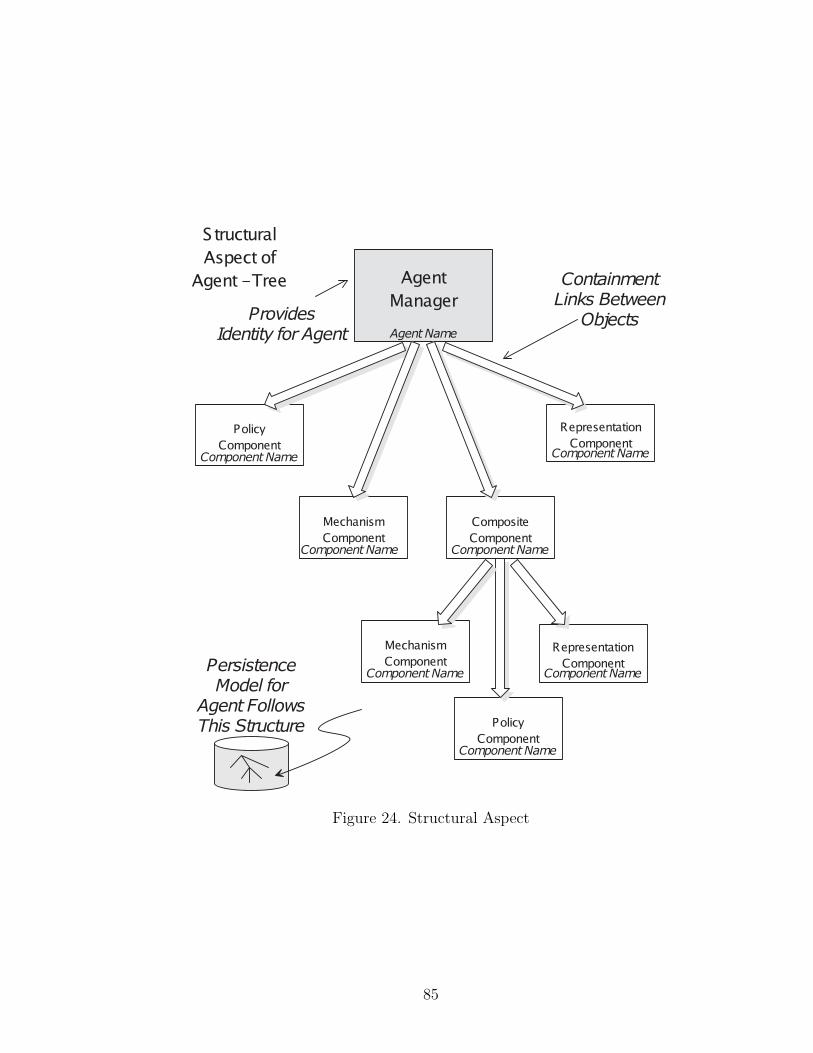
Figure 24. Structural Aspect
85
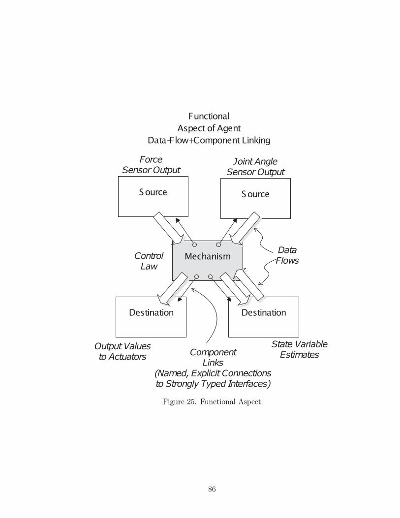
Figure 25. Functional Aspect
86

Figure 26. Policy Aspect
87
are built by aggregating and and managing sets of such simple links using other
components. Figure 28 shows a more complex connection that includes agent links
which are structured two way connections, as well as a relationship component
which organizes links and provides arbitration for one end of the relationship.
This type of connection if common in agents that take multiple inputs, like agents
that represent physical mechanisms on the robot. Figure 29 shows a connection
where each end of the relationship has a relationship component that acts as man-
ager and arbiter in the relationship. This type of connection is used to create
symmetric relationships like spreading activation between agents.
Structured Object-Oriented Model
The following descriptions and diagrams provide a more structured view of the
component object system that constitutes the agent-object model of IMA. The
model will be presented using a combination of description in English and a visual
notation called the Unified Modeling Language (UML). This practice is common
in the object-oriented software community and a variety of similar methods have
been combined into UML [14, 76, 39].
These components are also represented in Figure ?? which shows an overall
class diagram relating the components. The class diagram shows some of the
static structure and class hierarchy of IMA components.
One of the primary functions of this system of objects is to load an agent from
persistent storage and restore component links between all the objects in the agent.
This process is shown in Figure 31, a UML sequence diagram.
The corresponding states of each agent component are shown in Figure 32, a
88
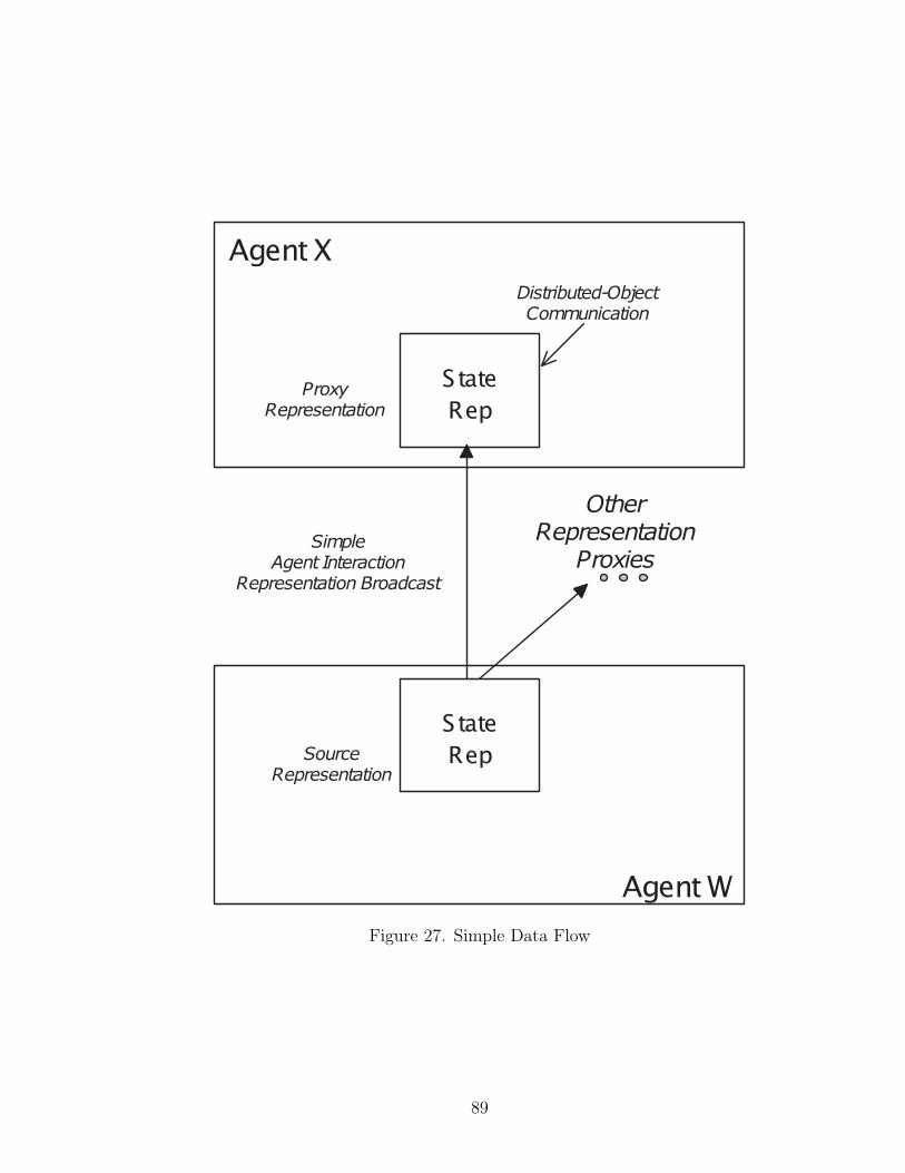
Figure 27. Simple Data Flow
89
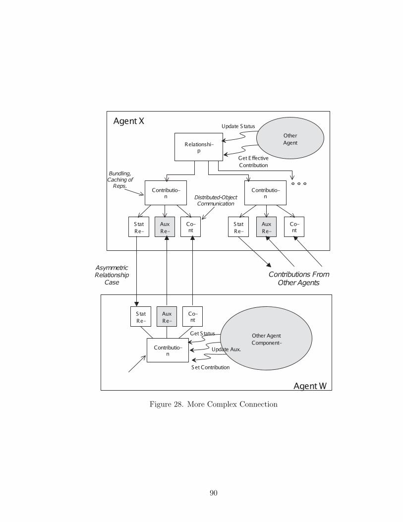
Figure 28. More Complex Connection
90
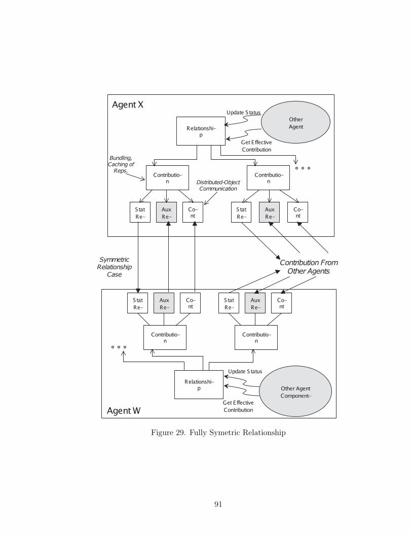
Figure 29. Fully Symetric Relationship
91
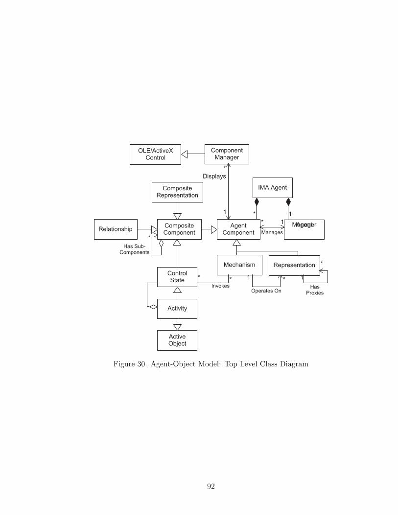
Figure 30. Agent-Object Model: Top Level Class Diagram
92

Figure 31. Agent-Object Model: Loading Sequence Diagram
93
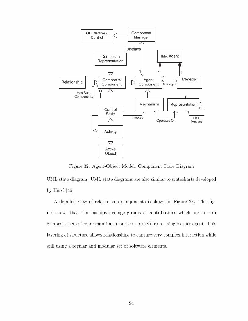
Figure 32. Agent-Object Model: Component State Diagram
UML state diagram. UML state diagrams are also similar to statecharts developed
by Harel [46].
A detailed view of relationship components is shown in Figure 33. This fig-
ure shows that relationships manage groups of contributions which are in turn
composite sets of representations (source or proxy) from a single other agent. This
layering of structure allows relationships to capture very complex interaction while
still using a regular and modular set of software elements.
94
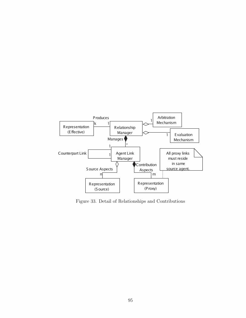
Figure 33. Detail of Relationships and Contributions
95

CHAPTER VI
EXAMPLE SYSTEMS USING THE IMA
This chapter describes the agent networks and some of the agent-object models
for agents used to create the control software for two quite different robot systems in
our laboratory. The development of these example systems is one kind of validation
of the IMA. This shows that the architecture works and can be used to build robot
control systems.
The explanations in the following sections are intended to reveal the types of
design decisions that were used in selecting the agents and relationships for the
ISAC and Helpmate systems. Several individual agents will also be described in
detail to show how component objects were used to create these agents.
ISAC: Dual-Armed Humanoid Robot
The first system used to test IMA is a dual-armed humanoid called ISAC.
ISAC provides a rich testbed for robot development due to the availability of
many sensors and actuators and the relatively unstructured tasks for which it is
used. ISAC is equipped with stereo color vision, voice I/O, and two arms with
force sensing.
Figure 34 shows a network of agents is used to realize a simple service-robot
demonstration on the ISAC system. The goal of this demonstration is to feed
soup to a disabled user who sits in front of the robot and asks for help using voice
commands.
96
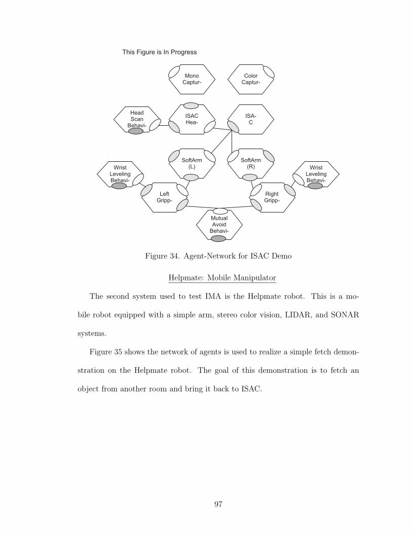
Figure 34. Agent-Network for ISAC Demo
Helpmate: Mobile Manipulator
The second system used to test IMA is the Helpmate robot. This is a mo-
bile robot equipped with a simple arm, stereo color vision, LIDAR, and SONAR
systems.
Figure 35 shows the network of agents is used to realize a simple fetch demon-
stration on the Helpmate robot. The goal of this demonstration is to fetch an
object from another room and bring it back to ISAC.
97
Figure 35. Agent-Network for Helpmate Demo
98

CHAPTER VII
EVALUATION OF THE ARCHITECTURE
In addition to the development of the robot control systems described in the
previous chapter, IMA has been evaluated further to try to discover how it affects
the development process and properties of the resulting system. One purpose of
software architecture is to provide useful abstractions that work at a level higher
than traditional programming methods [81] and confer some set of properties to
conforming systems. Another purpose of software architecture is to describe the
decomposition and integration between components as well as functionality in a
form that can be used to guide the development process and improve it in some
way. Typical evaluations of architecture include:
• Capability - The architecture provides a means to express concepts or de-
scribe systems that cannot be adequately described by other architectures.
• Scalability - The architecture adequately describes systems as they grow
larger, needing a comparable increase in resources.
• Productivity - The architecture provides abstractions (and tools) that in-
crease the productivity of the development process.
Capability is an issue that is too vague to measure ,and, in a rigorous sense, all
architectures that are Turing complete are equivalent because they can be used to
compute any computable function. Thus, it comes down to comparing how easy
it is to model some system within the architecture.
99

Scalability is an issue that is measured in many ways. However, scalability
does not mean that the architecture can help solve larger problems with the same
resources. It means that the architecture can solve larger problems with propor-
tionaly larger resources. These resources are often described in terms of processing
power or communications bandwidth between elements of ths system. Thus, archi-
tectures that are centralized frequently have problems with this measure, because
performance of the central component always limits growth of the resulting system.
Distributed architectures don’t escape this problem because growth of communica-
tions overhead between system elements can also swamp the system performance.
The IMA addresses scalability by avoiding centralized bottlenecks whenever pos-
sible and remaining asynchronous and distributed.
Productivity is an elusive measure of software architectures that has been cast
in many forms from lines-of-code (LOC) to newer more object-oriented measures,
such as reuse. Architecture can increase productivity by making the development
process of each component easier, by supporting high levels of component reuse, or
by supplying tools that automatically handle redundant or repetitive coding. The
IMA tries to achieve improved productivity by supporting very strict encapsulation
and high levels of reuse at the component level.
This evaluation is not complete.
100
CHAPTER VIII
CONCLUSIONS AND FUTURE RESEARCH
The IMA needs to be used and evaluated in a variety of ways so that we can
learn how to make better architectures. Over time the success or failure of the
IMA will become more apparent as measures of reuse and scalability are tested by
the continuing development process of service robot capability. Like any develop-
ment tool, the IMA needs other development tools to complement it. Much work
can be done to create tools that are built to develop within the IMA. Improved
graphical editors of agents and relationships are just one possible addition. Due
to the explicit nature of connectivity in IMA, it is possible to develop automatic
“connection checking” tools to ensure that a set of agents is configured according
to a specification. There is also the basic support for monitoring real-time as-
pects of agents and the possibility that monitoring could be added to continuously
guarantee certain timing deadlines within agents. As formal concepts about soft-
ware architecture are developed [3, 89], it may be possible to adapt the structured,
informal architecture presented herein to a more formal specification of a design
pattern for robot software.
101
APPENDIX A
DEFINITIONS OF IMA TERMS
The Intelligent Machine Architecture uses extensive technical terminology, some
of which is from object-oriented software engineering, current software technology,
robotics, multi-agent systems, and other research areas. This list is intended to
help our lab keep the pieces and terminology straight. Terminology is important
and influences how people think about development of a system and that this list is
intended to helps the reader handle the abstract terminology used in descriptions
of IMA. Loaded terms are shown in italics and will be defined further in the list
or are being defined as they are introduced. The reader should be familiar with
terms from robotics and from object-oriented programming.
IMA Terminology
Agent - This term is used in a wide variety of research areas to refer to different
things. In IMA an agent is an active software module that is a model for
some element of our robot system, skills, behavior, tasks, or environment.
By building links (called relationships) between agents we can capture data
and control flow between elements of our system. The network of agents is
intended to form the control system for a robot and model the robot system
at the same time. An IMA agent is also distinctive for its separation of
policy, state, and mechanism. Typical software systems mix policies and
mechanisms, but IMA agents keep these elements separate. Another way to
look at an agent is to view it as a collection of persistent component objects
102
that define the state, policy and mechanism of the agent. A multi-agent
system comprises a set of agents and the relationships between these agents.
The IMA employs a model of the robot system that uses multiple agents to
capture and encapsulate the different parts of the system. The concept of
agent is closely related to the concept of object in object-oriented software
engineering and agent as used by Marvin Minsky in Society of Mind.
Agent Types - These are classes of agents that roughly group agents by the aspect
of the robot system they model. Resource Agents own the hardware of the
system and supply the “bottom layer” of IMA (e.g., the sensors and actua-
tors of the robots). Behavior or Skill Agents connect sensors and actuators
to achieve certain types of sensory-motor dynamics (e.g., visual servoing).
Task Agents activate sets of Behavior or Skill Agents in sequences to achieve
a specific goal. Environment Agents represent objects or the user of the
robot system. These agents use the resources of the robot to engage in a
process called “anchoring” whereby they try to track the state of the real-
world entities that they model. Some environment agents represent purely
a-priori information like workspace boundaries or permanent objects in the
environment (The Table Agent for ISAC). The environment agents are a way
of bringing together what the robot “knows” about a particular element of
its environment. Environment Agents are not limited to mechanical things
like cups. One excellent environment agent would be the lighting agent that
would use camera data history to compute an ambient lighting estimate that
could then be used to influence the computation in other agents that used
103
camera images, for example. Agents may also be “collection agents” (i.e.,
they represent and manage collection or group of other agents) Collection
Agents might dynamically create instances (other agents) based on input
from the environment. The explicit structure of IMA agents makes this pro-
cess much simpler.
Representation - This term refers to an element of the “state space” of an agent
in a general sense. The concept of having representation components is that
there is a general way to encapsulate and refer to pieces of the state of an
agent. The type of representation may vary from floating point vectors to
text strings or images, but by classifying certain components as state, the dis-
tinction between state, policy, and mechanism can be made more clear than
in traditional programming. Representations can also be compound rep-
resentations that combine several smaller, simpler representations from the
same source (agent) into a larger representation. Finally, there are composite
representations that combine representations from several different sources
(other agents). Representation objects encapsulate the communication mech-
anism between different processes and computers in our network at a very
fine-grained level. The benefit of this encapsulation is that the mechanism
used for run-time communication of data may be varied without changing
any of the code (policies, mechanisms) that uses the representation objects.
The communication mechanism is based on a proxy-server model, where the
source agent that owns the representation has a representation component
that is a server to a set of proxy components that are remote copies of the
104
representation used by other agents. A remote (or proxy) representation
is like a window into a portion of the state of another agent. In IMA the
concept of representation (proxy and server) is implemented as a base class
that allows new representation types to be added easily as needed. Repre-
sentation base classes also provide a simple clock synchronizing mechanism
so that correlation of representations from the distributed system elements is
meaningful and allows sound decisions to be made within each agent based
on a synchronized virtual clock.
Policy - This term defines the strategy or, implicitly, the goal for an agent. The
policy of an agent represents the flow of control within an agent. IMA Agents
realize this control-state as a concurrent hierarchical finite state machine.
This is an advanced form of state machine but is in principle the same con-
cept. One way to view a policy is to think of it as a conditional plan. Most
advanced planning systems produce a conditional plan whose representation
is a finite state machine. The policy controls how to organize or sequence
computations (the mechanism) of the agent in response to external or internal
events. In IMA Agents, policy is implemented by a set of component objects
that are active (they have a thread of control and are scheduled for execution
by the underlying operating system) called activities and other components
called states. These two components can be combined to build state ma-
chines that control agent policy and operation sequencing. The conditions
and actions in the state machine descriptions can use fuzzy logic to provide
105
linguistic softness when required, but the state transition functions use tra-
ditional Boolean logic. The policy components are implemented as derived
classes from a base class that allows other active objects to be added easily as
needed. For example, a completely different policy mechanism could be used
within an agent (such as spreading activation). The policy uses a uniform
interface to activate or invoke components that provide the mechanism of
the agent.
Mechanism - The mechanism of the agent comprises a set of components that work
like traditional algorithms, but with policy removed. Thus, the mechanism of
the agent captures algorithms that are like transformations (representation
in to representation out) or functionals. For example, control laws, image
processing operations, and spatial transformations are all examples of mech-
anisms that are common in robotic systems. The mechanisms of an agent are
a set of possible actions from a planning standpoint and form a basis for the
agent policy. The mechanism is controlled by the policy and they cooperate
to create a continuous flow of computation that changes in response to events
entering the agent or the results of internal computations. Mechanisms are
the simplest components because they require little special support and are
essentially packages around traditional algorithms, so a simple base class is
defined to make it easy to add new mechanisms to the system as well. Many
of the elements of systems that are commonly called “modules” would be
called mechanisms under IMA. Together, mechanisms, representations, and
106
policies form a kind of highly structured object-oriented program that re-
alizes dynamically changing processing within an IMA Agent. The explicit
notion of “mechanism” helps to separate the two levels (robot-environment
and agent-object models) by allowing a system level entity to be described
and used independently of the mechanism that it uses internally for imple-
mentation.
Relationships - These are links between agents that capture certain common pat-
terns of interaction between agents. The relationship is implemented in IMA
as a base class from which new relationship types may be easily derived. Each
type of relationship is realized by a component object in each agent that sup-
ports the relationship type. Each relationship has a set of participants (other
agents that want to interact with the owner of a relationship) and an effective
state. The contribution of each participant is realized by a component object
(representation proxy). A relationship has its own mechanism and policy for
handling the contributions of the participants. Thus, a relationship is like
a package of reusable representation, policy, and state that allows an agent
to handle a certain type of interaction. Examples of relationships are the
motion schema relationship, which allows multiple participants to influence
the motion of robot mechanisms, and the spreading activation relationship,
which allows participants to create a distributed dynamic system that can
control sequencing at the agent level. Relationships can come in two broad
classes: semantic and non-semantic. The semantic relationship requires that
the implementation of two agents shares a common set assumptions in order
107
to operate (these are sometimes called logical links), while non-semantic re-
lationships do not require common semantics (or meaning). An example of
a semantic link command is “Go to x, y, z” which requires that the frame of
reference be shared to have any meaning, while an example of a non-semantic
link is “My activation is a” from spreading activation. It is possible in IMA to
create a kind of compound link between agents that has some semantic parts
as well as some non-semantic parts. Non-semantic links work well for con-
trolling context and modulating decisions, while semantic links provide very
compact forms for interaction (due to the inherent assumptions). IMA tries
to take advantage of both types of system organization by providing com-
pound links. Relationships between agents can also be written and used to
build up networks of agents that resemble class systems from object-oriented
modeling.
Component Object - These are blocks of software (sometimes called components
or software components) that are structured around the ability to access mul-
tiple interfaces at run-time using a binary interface standard (i.e., Language
Independent). An interface is merely a set of virtual function calls into the
object. Each interface to a component object is defined in an Interface Defi-
nition Language (IDL) that describes the method names, arguments, return
values, and properties needed to generate remote object calls to the interface.
Thus, the IDL tool provides a way to easily build interfaces that can be called
across process or machine boundaries. The interfaces on all the component
objects in IMA are defined in an IDL file. IMA Agents use a specific type
108
of component objects invented by Microsoft that follow a the Component
Object Model (COM). All COM objects support a special interface called
IUnknown. This interface exists only to allow other interfaces to be accessed
a run-time. IUnknown provides a kind of late binding for component objects.
Another way to look at component objects is to examine how they differ from
“regular objects” (i.e., C++): They support polymorphism by having dif-
ferent components that support the same interface. They support strong
encapsulation because they can be used only through an interface obtained
via the IUnknown interface. They support identity because all references to
the IUnknown interface on a component must be the same value. They do
not support implementation inheritance, because inheritance breaks encap-
sulation. Many aspects of component objects are relevant and useful and
described fully in the on-line help on every machine in our lab. Component
objects that support special interfaces for loading and storing them are called
persistent objects. A persistent object can be stored on disk and reloaded
to its previous state for later use. All IMA component objects support per-
sistence (built into the base classes), and thus the entire description of an
agent can be saved into a file and reloaded later.
Agent Component - Agent components are component objects that support a
certain set of interfaces (the IMA Base Interfaces) that provide persistence
as well as the ability to be accessed by name, respond to events, and be
monitored by other component objects. The other elements of an agent,
namely representations, policy components, relationships, and mechanisms,
109
are all types (sub-classes) of agent components because they all support the
set of agent component interfaces. The Framework classes (base classes) in
IMA facilitate the development of Agent Components and implement the
common interfaces and functions automatically. It is technically possible to
develop agent components purely from the interface specifications; however,
this would not take advantage of the framework classes that greatly reduce
the effort required.
Agent Manager - The agent manager is a special object that owns the rest of
the components within an agent and is responsible for managing persistence
(saving and loading) as well as for locating components within the agent. It
provides a name-space for the components of an agent, and this component
is really the “identity” of the agent within the agent system. When one
agent refers to another agent it is (at first) talking to interfaces of the agent
manager. The agent manager is a generic component implemented as a
class in IMA to be reused in all agents. Any component that implements
the interfaces defined on the agent manager could also serve as an agent
manager. This opens up the possibility of hierarchical agents (i.e., agents
that literally contain other agents); I am not sure how useful this will be in
our current systems.
Agent Shell - This is a program (in the traditional sense) that has an agent
manager that it uses to load an agent from persistent storage and use the
agent. The shell is a kind of tool for interacting with the agent. Several
types of shells can be useful. Graphical editor shells can be built to view
110
the agent components, edit properties, specify new policies, add or remove
components, etc. Simpler shells can be used to run agents without a user
interface, if needed. The agent shell merely provides a process address space
for the execution of the agent itself, and multiple agents can run within one
shell if needed. This emphasizes one major difference between typical soft-
ware systems and IMA agents: IMA agents are not programs. They are
collections of persistent, executable component objects that can be manipu-
lated in many ways and support a basic set of interfaces needed to be saved,
loaded, connected, and activated. By supporting this type of functionality,
IMA can provide a basis for a wide variety of development tools that aid
agent monitoring, debugging, design, evaluation, and possibly learning in
the future.
Software Framework - These are a set of C++ base classes that simplify the
process of writing component objects that are representations, mechanisms,
relationships, and policies. They do all of the dirty work and implement
the common or tedious portions required for integration of “standard code
fragments” with IMA. By deriving new components from these base classes,a
developer will end up with components that can be used as a portion of an
agent. The base classes allow developers to leverage a lot of development
work into development of new components and agents; for example, the
active components (threaded objects) took weeks to properly implement and
debug, but they can now be reused by typing a few lines of code in a class
definition in any new policy components.
111

APPENDIX B
ROBOTICS TERMINOLOGY
The following appendix will describe some of the terms and acronyms used in
this dissertation that relate to robotics systems and hardware to help a reader in
understanding the text.
LIDAR - This device a laser-radar device that provides a coarse range image by
measuring the time-of-flight of a laser beam while scanning it over an area.
Mobile robots use this sensor to detect obstacles.
112
APPENDIX C
UML NOTATION
Many of the class, sequence, state, and other diagrams in this disseration have
used a structured visual notation. This notation has evolved through several gener-
ations of object-oriented modeling and design and represents a very recent unifica-
tion of several approaches; hence the name, “Unified Modeling Language” (UML).
The UML provides a highly structured visual notation for modeling of software or
other systems and a good tutorial is provided by Fowler [39]. Currently, efforts
to formalize the semantics of UML are being developed, but it is still an infor-
mal technique for description of systems. However, UML is far from ad hoc and
represents the current best-practice method for effectively communicating object-
oriented software designs in visual form.
What follows is an extremely brief description of some UML notation elements.
A compact tutorial can be found in [39], with exhaustive technical definitions and
descriptions available in several new books on the subjectreferences here.
Class Diagrams
Class diagrams are used to show the entites in the software and the relationships
between them at a specific level of abstraction. Class diagrams use boxes and
lines to show classes and associations between classes. Some associations, like
inheritance, show the structure of the software. One aspect of UML that is new
is a notation to show interfaces as a separate concept from “object”, which is
a necessity for properly describing COM components and interfaces in the Java
113
language.
Sequence Diagrams
Sequence diagrams show the paths of threads of execution through a set of
objects and interfaces (typically defined in a class diagram). These sequences may
illustrate serial or concurrent operation.
State Diagrams
State diagrams show the control states of a set of objects. The control state is
represented in a state diagram as a concurrent, hierarchical, finite state machine
much like those described by Harel [46]. This allows state diagrams to show states,
events and concurrency at varying levels of abstraction in the model.
114
APPENDIX D
COMPONENT OBJECT SOFTWARE
The Intelligent Machine Architecture is based on recent developments in com-
ponent object software technology [64, 94]. Although it may have been faster to
implement an initial system using traditional elements, a component object soft-
ware technology was selected for the following reasons:
• Strong Encapsulation - Access to component functionality is always through
explicit interfaces with strong interface typing by globally unique identifiers.
• Dynamic Linking - Components can be loaded and unloaded under explicit
control, by unique identifier, during program execution.
• Interface Abstraction and Definition - Interfaces can be defined using an
abstract interface definition language (IDL) that aids in the generation of
component code and helps separate the interface from implementation de-
tails.
• Language Independence - Components can be implemented in any language
that supports function pointers, such as C++, VisualBasic and Java.
• Version Control - By strong typing of components (by globally unique identi-
fiers) it is possible to support multiple versions of components and smoothly
add new components and versions to a working system.
• Tool Support - Commercial off-the-shelf (COTS) tools now support compo-
nent software and also support the automatic generation of remote procedure
115
calling (RPC) code from the interface definition language.
By building IMA on this higher-level software model, the architecture itself
becomes language independent as well. Furthermore, the elements of IMA are
supported (at least at a low level) by commercially available software tools that
help reduce the cost and complexity of code development.
The Component Object Model (COM)
The particular component object technology used for this implementation of the
IMA is the Microsoft Component Object Model (COM) [64, 52, 45], although other
alternatives are available, such as CORBA [94]. This component object model is
an emerging de facto standard for the implementation of component software and
does not have the overhead associated with CORBA. COM is now beginning to
be supported on platforms other than the Microsoft Windows systems, including
some implementations on UNIX and Linux. COM provides a very flexible set of
primitive abstractions that support component software. Several complete descrip-
tions of COM and its internal mechanisms are available in the above references and
in both Brockschmidt [15], who describes how OLE is implemented using COM,
and Rogerson [74], who describes the fundamental aspects of COM and the newer
distributed component object model (DCOM) [20]. What follows is a brief intro-
duction to the concepts and facilities of COM as relevant to the development of
the IMA.
The primary abstraction in COM is the Interface. An Interface is a set of
functions and their calling signatures (arguments) grouped together with a unique
identifier called an Interface Identifier (IID). It is interesting to note that the
116
explicit representation of the interface as a unique IID can greatly simplify future
architectural tools that might test a system for connectivity between interfaces.
The interfaces in COM can be defined like pure-virtual classes in C++ but are
more easily defined using the Interface Definition Language (IDL). This language
is supported by a compiler that turns the interface definitions into header files for C
/ C++ code development, type-libraries that store the interface signature in binary
form, and the remoting code needed to call the interface across process boundaries.
The availability of this tool is a primary reason for the use of component object
software for the development of IMA.
Another abstraction in COM is the COM Class. A COM Class is a block of
executable code defined by a unique identifier called a Class Identifier (CLSID). A
COM Class implements a set of COM Interfaces by providing the base interface
IUnknown. The code for the class may reside in a traditional executable program
or in a dynamic link library(DLL). In either case the operating system provides
a mechanism to automatically load code for requested COM classes and unload
these classes when they are no longer in use.
The IUnknown interface is mandatory for all COM Components and allows
client software (or other components) to request additional interfaces from the
component at run-time. It is thus a kind of program-controlled linking. However, it
prevents clients from knowing anything about the “inheritance” of the component
they are using. The component is merely seen as a set of interfaces. IUnknown
provides an additional important function for any COM component. The value
of the IUnknown pointer is the identity of the component. Thus, given any two
IUnknown pointers it is valid to compare the pointer values to test for component
117

object identity.
By implementing the IUnknown interface, COM components also support poly-
morphism. Thus, any two components that implement the same interface are said
to be polymorphic with respect to that interface. Furthermore, any two compo-
nents that implement the same set of interfaces are interchangeable as far as a
client program is concerned. The object model for the basic COM interface and
relationship between interfaces is shown in Figure 36.
Special COM / OLE Interfaces
Microsoft has also defined suites of interfaces based on COM that provide the
foundation for other software technologies such as OLE, ActiveX or DirectX, etc.
These suites of interfaces provide a range of component-object-based services to
any program developed using COM. Some important subsets of interfaces are:
• IPersist Interfaces - This set of interfaces allows objects to tell clients they
support various forms of persistence, such as streams and storages.
• IDispatch Interface - Allows objects to support named methods and proper-
ties through a special “interpreted function call” interface, which is shown
in Figure 37.
• ITypeInfo Interface - Components have an associated type library that de-
fines the signatures of all their methods in binary form.
• IStream Interface - This interface is implemented by the operating system
to support persistence of objects to stream-like media (files, memory buffers,
transport streams).
118

Figure 36. UML Model of COM
119

• IStorage Interface - This interface is implemented by the operation system
to support hierarchical object databases to be stored onto various media.
120
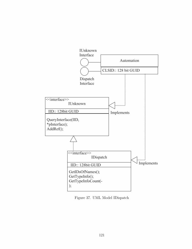
Figure 37. UML Model IDispatch
121
APPENDIX E
USING THE CODE FRAMEWORK
Introduction
Most engineers are not trained to develop reusable software; however, it is
essential to embrace this new mode of development to simplify development of
more complex systems. It may be tempting to assume that everything in IMA is
an agent because the concept of multi-agent systems is appealing and the term is
used (misused) in many contexts. This is not the case; only things that represent
a fully encapsulated concept can be IMA agents. This completely rules out the
concept of a general object-recognition agent, because such an agent would break
the encapsulation of many parts of the system and would ultimately be a point
of failure. Instead, the elements of the world that are modeled in software (i.e.,
the utensils in the ISAC demo) are captured as agents, and each agent uses an
object-recognition algorithm as a mechanism based on its particular policy. This
type of system structure has three very important advantages: (1) It is inherently
parallel and allows agents on separate processors to run mechanisms in parallel
for increased speed. (2) It acknowledges that a mechanism (object-recognition
algorithm) and the agent (a software model of a physical entity) are at different
levels of abstraction. (3) Multiple mechanisms (algorithms) can be supported and
selected by an agent based on the situation and new algorithms are easily added to
increase the capability of the system. This example extends to employing various
control algorithms, multiple visual servoing algorithms, tracking algorithms, etc.
To achieve this kind of flexibility in a system, it is essential to separate policy from
122

mechanism and to separate the system level model from the implementation level
model.
Thus, not everything is an agent. Most of the development effort in IMA will
be spent in developing agent components (mechanisms, policies, relationships, and
representations). The code framework focuses on simplifying and speeding up this
process for developers. Some members of a development team will develop com-
ponents, while others will work on building the agents that use these components.
This means that there are several types of development work under IMA, while in
the past teams used a “one person = one module” philosophy. This also leads into
an example of how IMA is designed to evolve over time. Given a system operating
with a set of agents that does a feeding demonstration, a developer discovers an
improved control algorithm. Under IMA, only the control algorithm itself will need
to be implemented and inserted into an existing agent. The system level model is
not changed and this is conceptually correct. The policy of the controller agent will
also have to be changed to use the new algorithm, but after that, a whole working
system results with the new algorithm in place. Most of the code of an agent
remains unchanged and is reused (copied) in new versions of the agent, while new
algorithms (mechanisms) or policies are added to improve operation. This leads to
one of the major drawbacks of the IMA. Bootstrapping the system (building the
initial set of agents and components to get things started) is extremely difficult
and little or no results are seen until it is nearly finished. This is a difficult hurdle
and one that is shared by many systematic development methods that focus on
architecture driven development of software.
The basic classes used to create components within the IMA agent-object model
123
are shown in Figure 38.
Writing Simple Agent Components
These components are derived from the base class CComponentImpl which
provides:
Writing Representation Components
These components are derived from the base class CRepresentationImpl.
Writing Relationship Components
These components are derived from the base class CRelationshipImpl.
Writing Component Managers
These components are derived from the base class CComponentManagerImpl
and all OLE control base classes. Thus, they are OLE custom controls that are
hooked into other IMA interfaces.
Writing Agent Shell Programs
Agent shell programs provide a process space and implement an object that
supports the agent manager interfaces for IMA. Any program can serve as a shell
program that implements the agent manager interfaces. The program can be
a simple console program or a full Windows program. By writing a Windows
program that supports the commonly available functionality of an OLE container
it is possible to configure a suite of component managers to view and interact
visually on the screen with the components of an agent.
124
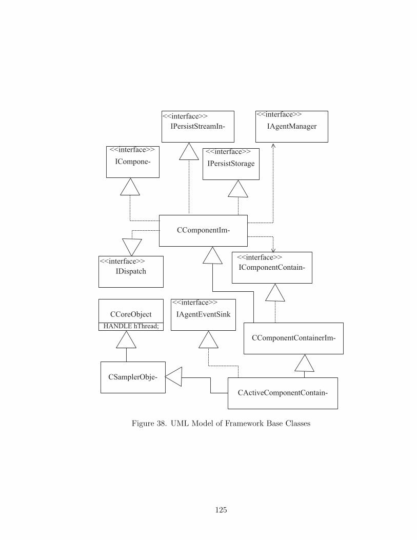
Figure 38. UML Model of Framework Base Classes
125
Writing Agent Tools
Agent tools are programs that understand the file format used to store the agent
components in persistent storage as well as the basic IMA component interfaces.
These programs can be used to automatically generate or configure agents from
scripts, for example.
126
APPENDIX F
SYNCHRONIZATION MECHANISM
The purpose of this synchronization mechanism is to allow agents to model
and offset the skew between their local clocks due to message delay and real clock
skew. The mechanism used is based on message exchange (Remote Procedure Call
is a kind of message exchange for these purposes), and it allows two agents to
estimate clock skew using just two procedure calls. Although this mechanism can
also be used to create a kind of global clocking in a system, IMA does not have a
central “global” entity to keep this clock. The mechanism used for synchronization
between agents in IMA is based on a simple distributed clocking algorithm that uses
time-stamps to estimate clock skew between agents. The primary assumption of
this algorithm is that the delay between the source and destination is symmetric for
message traffic, at least on average. This algorithm is described by Levi [56] and is
intended for use in LAN environments. Should the architecture be used in a WAN
environment, another clocking mechanism may have to be employed. However,
the low cost of this method and the high accuracy possible with it justify its use
in the current implementation. Other distributed clocking schemes are available
like logical clocks [66], but they frequently sacrifice the notion of time intervals to
achieve absolutely monotonic labeling of events in the system. Thus, there is no
notion of “time” except that event A happened before event B.
The synchronization mechanism is used to establish an agent-relative clock for
each agent in the system so that any information about time sent from one agent in
the system can be interpreted properly by another agent in the system. Figure 39
127

Figure 39. Agent Time Synchronization Mechanism
shows the messages and associated times for synchronization between two agents
i and j.
After the first message from i to j, agent j can compute the time difference:
d1 = Cj(T2)−Ci(T1), and it can be seen that d1 = uji +(e1−e2). Now agent j sends
another message back to agent i who computes the value of the time difference:
d2 = Ci(T4) − Cj(T3), and again it can be seen that: d2 = uij + (e3 − e4), if the
error values in the clock readings are modeled as clock skew and additional error
terms: (e1 − e2) = Sj − E1j where Sj is the clock skew (offset) from i to j.
Once agent i is in possession of the second timestamped message, it can com-
pute the following:
d1 − d2
2= Sj +
uji − ui
j
2−
E1j − E2
j
2(8)
If the communication delay is symmetric between the two agents, then the
clock skew Sj is known within an error on the order of the sampling error of
the individual clocks in the agents. The same scheme can be applied again in the
opposite direction so that both agents can compute the skew of the clock relative to
the other agent using the further messages on the diagram. After synchronization,
128
agent clocks will drift apart due to imperfections in the match of system crystals
or other inherent differences. However, this synchronization mechanism is built
into the base-classes that make up the IMA Framework, and the skew is updated
as a part of each agent interaction. Thus, this mechanism is typically applied at
least once every few seconds between agents, and the drift of synchronization over
the timespan of a few seconds is quite minimal.
A series of experiments were run to test that such a synchronization mechanism
would be valid for time intervals that are typical of the modules in our systems (on
the order of several seconds). Timing is based on a hardware performance clock
that is represented as a 64-bit integer that is made available under the Win32
API. The frequency of the clock varies from system to system, but this frequency
is also made available as a run-time parameter that can be used to convert clock
ticks into highly accurate timing values. This hardware clock runs many orders
of magnitude faster than the scheduling clock of the operating system (100Khz to
200Mhz) depending on the processor type, giving the possibility of microsecond
timing resolution. Times are converted to double precision floating point numbers
of seconds when used in IMA and based on a time zero at agent startup. This
representation will preserve microsecond accuracy over intervals up to ten thousand
seconds (2.7 hours) in length, and millisecond accuracy over intervals of days of
system operation.
129
REFERENCES
[1] Philip E. Agre and David Chapman. What are plans for? In DesigningAutonomous Agents: Theory and Practice from Biology to Engineering andBack, volume 6, pages 17–34. MIT Press/Elsevier Science Publishers, 1990.
[2] James Albus. A reference model architecture for intelligent systems design.Technical Report 5502, National Institute of Standards and Technology, 1994.
[3] Robert J. Allen. A Formal Approach to Software Architecture. PhD thesis,Carnegie Mellon University, 1997.
[4] John R. Anderson. The Architecture of Cognition. Harvard University Press,1983.
[5] Ronald C. Arkin. Towards the unification of navigational planning and reactivecontrol. In AAAI Spring Symposium on Robot Navigation, 1989.
[6] Ronald C. Arkin. Integrating behavioral, perceptual and world knowledge inreactive navigation. Robotics and Autonomous Systems, 6:105–122, 1990.
[7] Ronald C. Arkin. Just what is a robot architecture anyway? Turing equivalencyversus organizing principles. In AAAI Spring Symposium: Lessons Learnedfrom Implemented Software Architectures for Physical Agents, 1995.
[8] Christof Baeijs, Yves Demazeau, and Luis Alvares. SIGMA: Application ofmulti-agent systems to cartographic generalization. In Walter Van der Veldeand John W. Perram, editors, Agents Breaking Away: 7th European Workshopon Modelling Autonomous Agents in a Multi-Agent World, pages 163–176.Springer-Verlag, January 1996.
[9] Sugato Bagchi, Gautam Biswas, and Kazuhiko Kawamura. Interactive taskplanning under uncertainty and goal changes. Robotics and AutonomousSystems, 18:157–167, 1996.
[10] Sugato Bagchi and Kazuhiko Kawamura. An architecture for a distributedobject-oriented robotic system. In IEEE/RSJ International Conference onIntelligent Robots and Systems, volume 2, pages 711–716, July 1992.
[11] Edward A. Bender. Mathematical Methods in Artificial Intelligence. IEEEComputer Society Press, 1996.
[12] Uwe Beyer and Frank Smieja. JANUS: A society of agents. Technical ReportGMD 840, German National Research Centre for Computer Science (GMD),Germany, 1994.
[13] Bruce M. Blumberg and Tinsley A. Galyean. Multi-level direction of au-tonomous creatures for real-time virtual environments. In Computer Graph-ics Proceedings, SIGGRAPH-95, August 1995.
130

[14] Grady Booch. Object-Oriented Analysis and Design. Addison-Wesley, 1994.
[15] Craig Brockschmidt. Inside OLE : Second Edition. Microsoft Press, Redmond,WA, 1995.
[16] F. P. Brooks. No silver bullet: Essence and accidents of software engineering.Computer, 20(4):10–19, April 1987.
[17] Rodney A. Brooks. A robust layered control system for a mobile robot. IEEEJournal of Robotics and Automation, RA-2(1), March 1986.
[18] Rodney A. Brooks. A robot that walks; emergent behaviors from a carefullyevolved network. A.I. Memo 1091, 1989.
[19] Rodney A. Brooks. The whole iguana. In Michael Brady, editor, RoboticsScience. The MIT Press, 1989.
[20] Nat Brown and Charlie Kindel. Distributed component object model protocol– dcom/1.0. Technical report, Microsoft, Redmond, Washington, May 1996.
[21] Frank Buschmann, Regine Meunier, Hans Rohnert, Peter Sommerlad, andMichael Stal. Pattern-Oriented Software Architecture : A System of Pat-terns. John Wiley and Sons, 1996.
[22] J. Cameron, D. MacKenzie, K. Ward, R. C. Arkin, and W. Book. Reac-tive control for mobile manipulation. In IEEE Conference on Robotics andAutomation, 1993.
[23] Erich Camma, Richard Helm, Ralph Johnson, and John Vlissides. DesignPatterns: Elements of Reusable Object-Oriented Software. Addison-Wesley,1995.
[24] M. Colombetti, M. Dorigo, and G. Borghi. Behavior analysis and training–amethodology for behavior engineering. IEEE Transactions on Systems, Manand Cybernetics, 26(3), 1996.
[25] Milton Correa and helder Coelho. Around the architectural agent approach.In Cristiano Castelfranchi and Jean-Pierre Muller, editors, From Reaction toCognition: 5th European Workshop on Modelling Autonomous Agents in aMulti-Agent World, pages 172–185. Springer-Verlag, August 1993.
[26] P. Courtois. On time and space decomposition of complex structures. Com-munications of the ACM, 28(6):596, 1985.
[27] John J. Craig. Introduction to Robotics. Addison-Wesley, 1989.
[28] Jill D. Crisman and George Beckey. Grand challenges for robotics and au-tomation: The 1996 ICRA panel discussion. IEEE Robotics and AutomationMagazine, 3(4):10–16, December 1996.
131
[29] Daniel C. Dennett. Consciousness Explained. Little, Brown and Company,1991.
[30] Kevin Dowling. Robotics:comp.robotics frequently asked questions. Available via anonymous ftp fromftp://rtfm.mit.edu/pub/usenet/nes.answers/robotics-faq, 1994.
[31] Edmund H. Durfee and Thomas A. Montgomery. A hierarchical protocol forcoordinating multiagent behaviors. In Proceedings of The Eighth NationalConference on Artificial Intelligence, pages 86–93, 1990.
[32] L. Erman, J. Lark, and F. Hayes-Roth. ABE: An environment for engi-neering intelligent systems. IEEE Transactions on Software Engineering,14(12):1758, 1988.
[33] E.A. Feigenbaum and J. Feldman. Computing machinery and intelligence. InComputers and Thought. McGraw Hill, New York, 1963.
[34] Cynthia Ferrell. Robust agent control of an autonomous robot with manysensors and actuators. Master’s thesis, Massachusetts Institute of Technology,1991.
[35] R. E. Fikes and H. J. Nilsson. STRIPS: A new approach to the application oftheorem proving to problem solving. Artificial Intelligence, 2(3-4):189–208,1971.
[36] R. James Firby. Lessons learned from the animate agent project (so far).In AAAI Spring Symposium: Lessons Learned from Implemented SoftwareArchitectures for Physical Agents, 1995.
[37] R. James Firby. Task execution: Interfacing to reactive skill networks. InDon’t Know, pages 146–153, 1995.
[38] Klaus Fischer, Jorg P. Muller, and Markus Pischel. A pragmatic BDI architec-ture. In Intelligent Agents II: IJCAI ’95 Workshop, pages 203–218, August1995.
[39] Martin Fowler and Kendall Scott. UML Distilled: Applying the StandardObject Modeling Language. Addison-Wesley, 1997.
[40] J. Gall. Systemantics: How Systems Really Work and How They Fail. TheGeneral Systemantics Press, Ann Arbor, MI, 1986.
[41] David Garlan and Mary Shaw. An introduction to software architecture. Tech-nical Report CMU-CS-94-166, Carnegie Mellon University, School of Com-puter Science, Pittsburgh, PA, January 1994.
[42] Fausto Giunchiglia and Enrico Giunchiglia. Ideal and real belief about belief:Some intuitions. In Walter Van der Velde and John W. Perram, editors,Agents Breaking Away: 7th European Workshop on Modelling AutonomousAgents in a Multi-Agent World, pages 1–12. Springer-Verlag, January 1996.
132
[43] Takashi Gomi and Kohichi Ide. Vision based navigation for an office messengerrobot. In IEEE/RSJ International Conference on Intelligent Robots andSystems, 1994.
[44] Takashi Gomi and Phillip Volpe. Collision avoidance using behavioral-basedai techniques. In Intelligent Vehicles Symposium, 1993.
[45] Crispin Goswell. The COM programmer’s cookbook. Technical report, Mi-crosoft, Redmond, Washington, 1995.
[46] David Harel. Statecharts: A visual formalism for complex systems. In Scienceof Computer Programming, volume 8, pages 231–274. North-Holland, 1987.
[47] Henry H. Hexmoor, Johan M Lammens, and Stuart C. Shapiro. An au-tonomous agent architecture for integrating ‘unconscious’ and ‘conscious’,reasoned behaviors. In Computer Architectures for Machine Perception 93,1993.
[48] Henry H. Hexmoor, Johan M. Lammens, and Stuart C. Shapiro. An au-tonomous agent architecture for integrating unconscious and conscious, rea-soned behaviors. In AAAI Spring Symposium: Lessons Learned from Imple-mented Software Architectures for Physical Agents, 1995.
[49] Carlos A. Iglesias, Jose C. Gonsalez, and Juan R. Velasco. MIX: A general pur-pose multiagent architecture. In M. Wooldridge, J.P. Muller, and M. Tambe,editors, Intelligent Agents II: IJCAI ’95 Workshop, pages 251–267. Springer-Verlag, August 1995.
[50] Kazuhiko Kawamura and Robert Todd Pack. Object-based software archi-tecture for service robot development. In ICAR ’97 Workshop on ServiceRobots, page to add, July 1997.
[51] Kazuhiko Kawamura, D. Mitch Wilkes, Todd Pack, Magued Bishay, and J. Bar-ile. Humanoids: Future robots for home and factory. In International Sym-posium on Humanoid Robots, pages 53–62. Waseda University, Tokyo, Japan,October 1996.
[52] Charlie Kindel. Designing COM interfaces. Technical report, Microsoft,Redmond, Washington, 1995.
[53] Jana Kosecka and Luca Bogoni. Application of discrete events systems formodeling and controlling robotic agents. In IEEE Conference on Roboticsand Automation, pages 2557–2562, 1994.
[54] J. Laird and S. Newell. An analysis of SOAR as an integrated architecture.In SIGART Bulletin 2, pages 85–90, 1991.
[55] J. Laird, S. Newell, and P. Rosenbloom. SOAR: an architecture for generalintelligence. Artificial Intelligence, 33:1–64, 1987.
133
[56] Shem-Tov Levi and Ashok K. Agrawala. Real Time System Design. McGraw-Hill, 1990.
[57] William Lim. An agent-based approach for programming mobile robots. InIEEE Conference on Robotics and Automation, pages 3584–3589, 1994.
[58] Ren C. Luo and Michael G. Kay. Multisensor integration and fusion in intelli-gent systems. IEEE Transactions on Systems, Man and Cybernetics, 19(5),1989.
[59] Pattie Maes. Behavior-based artificial intelligence. In Proceedings of the 2ndConference on Adaptive Behavior. MIT Press, 1993.
[60] Pattie Maes. Modeling adaptive autonomous agents. In Artificial Life, 1,pages 135–162, 1994.
[61] Pierre Marcenac. The multiagent approach. IEEE Potentials, 16(1):19–22,1997.
[62] James Mayfield, Yannis Labrou, and Tim Finin. Evaluation of KQML asan agent communication language. In M. Wooldridge, J.P. Muller, andM. Tambe, editors, Intelligent Agents Volume II – Proceedings of the 1995Workshop on Agent Theories, Architectures and Languages. Springer-Verlag,1996.
[63] David McFarland and Thomas Bosser. Intelligent Behavior in Animals andRobots. The MIT Press, 1993.
[64] Microsoft. The Microsoft object technology strategy: Component software.Technical report, Microsoft, Redmond, Washington, February 1996.
[65] Marvin Minsky. The Society of Mind. Simon and Schuster, 1986.
[66] Sape Mullender. Distributed Systems. Addison-Wesley, 1993.
[67] Jorg P. Muller. The Design of Intelligent Agents. Springer-Verlag, Berlin,1996.
[68] David John Musliner. CIRCA: Cooperative Intelligent Real-Time Control Ar-chitecture. PhD thesis, University of Michigan, 1993.
[69] Lars Overgaard, Henrik G. Petersen, and John W. Perram. Motion planningfor an articulated robot: A multi-agent approach. In John W. Perram andJean-Pierre Muller, editors, Distributed Software Agents and Applications:6th European Workshop on Modelling Autonomous Agents in a Multi-AgentWorld, pages 206–219. Springer-Verlag, August 1994.
[70] Robert Todd Pack, Joe L. Christhoper, and Kazuhiko Kawamura. Arubbertuator-based structure-climbing inspection robot. In ICRA ’97, pages1869–1874, April 1997.
134
[71] Robert Todd Pack, M. Wilkes, G. Biswas, and K. Kawamura. Intelligentmachine architecture for object-based system integration. In AIM ’97, pageto add, June 1997.
[72] Anand S. Rao. Agentspeak(l): BDI agents speak out in a logical computablelanguage. In Walter Van der Velde and John W. Perram, editors, AgentsBreaking Away: 7th European Workshop on Modelling Autonomous Agents ina Multi-Agent World, pages 42–71. Springer-Verlag, January 1996.
[73] Elaine Rich and Kevin Knight. Artificial Intelligence. McGraw Hill, 1991.
[74] Dale Rogerson. Inside COM: Microsoft’s Component Object Model. MicrosoftPress, Redmond, WA, 1997.
[75] Julio K. Rosenblatt. DAMN: A distributed architecture for mobile navigation.In AAAI Spring Symposium: Lessons Learned from Implemented SoftwareArchitectures for Physical Agents, 1995.
[76] James Rumbaugh, Michael Blaha, William Premerlani, Frederick Eddy, andWIlliam Lorensen. Object Oriented Analysis and Design. Prentice-Hall,1991.
[77] Stuart Russell and Peter Norvig. Artificial Intelligence: A Modern Approach.Prentice-Hall, New Jersey, 1995.
[78] Ashraf Saad. A survey of robot architectures and robotic teamwork in the fieldsof decentralized robotics and distributed artificial intelligence. IntelligentRobotics Lab, Vanderbilt University, 1993.
[79] Alessandro Saffiotti, Kurt Konolige, and Enrique H. Ruspini. A multivaluedlogic approach to integrating planning and control. Technical report, Artifi-cial Intelligence Center: SRI International, 1994.
[80] Mary Shaw and David Garlan. Software Architecture: Perspecitvies on anEmerging Discipline. Prentice Hall, 1996.
[81] Mary Shaw, R.DeLine, D.Klein, T.Ross, D.Young, and G.Zelesnik. Abstrac-tions for software architecture and tools to support them. IEEE Transactionson Software Engineering, April 1995.
[82] Y. Shoham. Agent-oriented programming. Artificial Intelligence, 60:51–92,1993.
[83] H. Simon. The Sciences of the Artificial. The MIT Press, Cambridge, MA,1982.
[84] Frank J. Smieja and H. Muhlenbein. Reflective modular neural network sys-tems. Technical Report GMD 633, German National Research Centre forComputer Science (GMD), Germany, March 1992.
135

[85] John Stewart. The implications for understanding high-level cognition of agrounding in elementary adaptive systems. Robotics and Autonomous Sys-tems, 16(2-4):107–116, 1995.
[86] Takashi Suehiro and Kosei Kitagaki. Multi-agent based implementation ofrobot skills. In IEEE Conference on Robotics and Automation, pages 2976–2981, 1996.
[87] Takashi Suehiro, Hironobu Takahashi, and Hiroshi Yamakawa. Research onreal world adaptable autonomous systems: Development of a hand-to-handrobot. In RWC 1997, 1997.
[88] Janos Sztipanovits, Gabor Karsai, and Hubertus Franke. MULTIGRAPH: Anarchitecture for model-integrated computing. In ICECCS’95, pages 361–368,November 1995.
[89] Janos Sztipanovits, Gabor Karsai, and Hubertus Franke. Model-integratedprogram synthesis environment. In IEEE Symposium on Engineering ofComputer Based Systems, March 1996.
[90] S.R. Thomas. PLACA, an Agent Oriented Programming Language. PhDthesis, Stanford University, 1993.
[91] Laurence Urdang, editor. The Random House College Dictionary. RandomHouse, Inc., 1984.
[92] Michael Wooldridge. Time, knowledge and choice. Technical report, De-partment of Computing, Manchester Metropolitan University, Chester Street,Manchester M1 5GD, United Kingdom, 1994.
[93] Michael Wooldridge. Time knowledge and choice. In M. Wooldridge, J.P.Muller, and M. Tambe, editors, Intelligent Agents II: IJCAI ’95 Workshop,pages 79–96. Springer-Verlag, August 1995.
[94] Zhonghua Yang and Keith Duddy. CORBA: A platform for distributed objectcomputing. ACM Operating Systems Review, 30(2):4–31, April 1996.
136

ELECTRICAL ENGINEERING
IMA: THE INTELLIGENT MACHINE ARCHITECTURE
ROBERT TODD PACK
Thesis under the direction of Professor K. Kawamura
This dissertation discusses the problem of designing software for intelligent robot
control from a software architecture viewpoint. The motivation for this work and
the issue of what constitutes an intelligent control system is discussed. The com-
plexity of building an integrated intelligent system is described, and system ar-
chitecture is offered as a tool to manage that complexity. General properties of
system architectures are described and current architectures are reviewed, includ-
ing classical Artificial Intelligence, Behavior-Based Artificial Intelligence, hybrids,
and related approaches. Classical Artificial Intelligence (AI) has typically used
a knowledge-based decomposition of the design problem, Behavior-Based AI de-
composes this problem into goal-achieving modules called behaviors, and hybrid
approaches use elements of each type. A proposal for the development of a novel
system architecture is included, and potential applications are discussed. This new
architecture combines principles from object-oriented software engineering, previ-
ous approaches to intelligent machine software, and current ideas about software
architecture to produce a new pattern for guide intelligent machine software.
We are developing this new software architecture, called the Intelligent Machine
Architecture, for the engineering of intelligent control systems. This new approach
breaks an intelligent control system into groups of agents and provides a model of
relationships that link agents. The architecture features component object-based
software design, uses a new approach to object-based software development and is
suitable for implementation in a distributed processing environment.
The approach will be tested by a group of twenty software developers as we
build new intelligent control software for several service robots in our lab. Thus,
the key feature of this architecture is its ability to support the effort of software
intergration involving many partial solutions to the problem of intelligent control
into a single coherent robot control system.
Approved Date
Recommended