IEC 61850 Substation Solutions
© 2014 Moxa Inc., All Rights Reserved. The MOXA logo is a registered trademark of Moxa Inc. All other logos appearing in this catalog are the intellectual property of the respective company, product, or organization associated with the logo.
The AmericasMoxa AmericasToll Free: 1-888-MOXA-USATel: +1-714-528-6777Fax: [email protected]
Moxa Brazil Tel: +55-11-2495-3555Fax: [email protected]
EuropeMoxa GermanyTel: +49-89-3700-399-0Fax: [email protected]
Moxa France Tel: +33-1-30-85-41-80Fax: [email protected]
Asia-PacificMoxa TaiwanTel: +886-2-8919-1230Fax: [email protected]
Moxa India Tel: +91-80-4172-9088Fax: [email protected]
Moxa RussiaTel: +7(495)287-09-29Fax: +7(495)269-09-29 [email protected]
ChinaMoxa ShanghaiTel: +86-21-5258-9955Fax: [email protected]
Moxa Beijing Tel: +86-10-6872-3959/61
Fax: +86-10-6872-3958
Moxa Shenzhen Tel: +86-755-8368-4084/94
Fax: +86-755-8368-4148
Moxa UK Tel: +44-1844-355-601Fax: [email protected]
Moxa Sales and Marketing Headquarters
Moxa Design and Engineering Headquarters
Your Trusted Partner in AutomationMoxa is a leading manufacturer of industrial networking, computing, and automation solutions. With over 25
years of industry experience, Moxa has connected more than 30 million devices worldwide and has a
distribution and service network that reaches customers in more than 70 countries. Moxa delivers lasting
business value by empowering industry with reliable networks and sincere service for automation systems.
Moxa Corporate Plaza
601 Valencia Ave., Suite 200
Brea, CA 92823, U.S.A.
Toll Free: 1-888-669-2872
Tel: +1-714-528-6777
Fax: +1-714-528-6778
Fl. 4, No. 135, Lane 235, Baoqiao Rd.
Xindian Dist., New Taipei City,
Taiwan, R.O.C.
Tel: +886-2-8919-1230
Fax: +886-2-8919-1231
P/N: 1900001401200
21www.moxa.com/substation www.moxa.com
Leading TechnologiesIndustry’s first IEC 61850 switch with MMS data modeling: SNMP/MMS management with integrated network monitoring solutions for power substation SCADA applications
Noise Guard: The world’s only wire speed zero packet loss technology that exceeds IEEE 1613 class 2
Industry’s first integrated PRP/HSR redundancy box with zero recovery time
Turbo Chain: Self-Healing redundancy technology ensures non-stop wind power operation
Patented computing platform for heat dissipation with wide temperature tolerance
MXcloud: Cloud management for solar energy monitoring
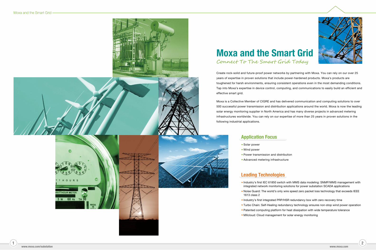
Moxa and the Smart GridConnect To The Smart Grid Today
Application FocusSolar power
Wind power
Power transmission and distribution
Advanced metering infrastructure
Create rock-solid and future-proof power networks by partnering with Moxa. You can rely on our over 25
years of expertise in proven solutions that include power-hardened products. Moxa’s products are
toughened for harsh environments, ensuring consistent operations even in the most demanding conditions.
Tap into Moxa’s expertise in device control, computing, and communications to easily build an efficient and
effective smart grid.
Moxa is a Collective Member of CIGRE and has delivered communication and computing solutions to over
500 successful power transmission and distribution applications around the world. Moxa is now the leading
solar energy monitoring supplier in North America and has many diverse projects in advanced metering
infrastructures worldwide. You can rely on our expertise of more than 25 years in proven solutions in the
following industrial applications.
Moxa and the Smart Grid
43
IEC 61850 Makes Substations Smarter
www.moxa.com/substation
IEC 61850 Makes Substations Smarter
www.moxa.com
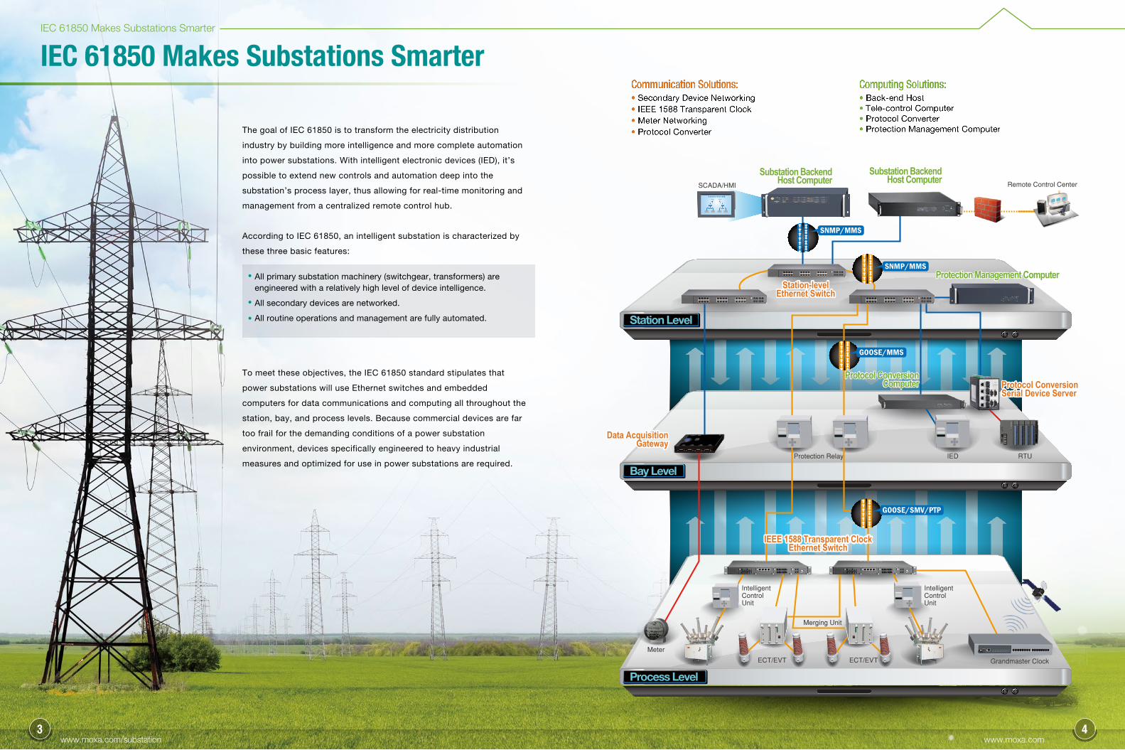
All primary substation machinery (switchgear, transformers) are engineered with a relatively high level of device intelligence.
All secondary devices are networked.
All routine operations and management are fully automated.
Process Level
Bay Level
Station Level
Substation BackendHost Computer
Protocol ConversionComputer
Protection Management Computer
Substation BackendHost Computer
Substation BackendHost Computer
Station-levelEthernet Switch
Protocol Conversion Serial Device Server
Data AcquisitionGateway
Station-levelEthernet Switch
Protocol ConversionComputer Protocol Conversion
Serial Device Server
Data AcquisitionGateway
Protection Management Computer
Substation BackendHost Computer
SCADA/HMI
Protection Relay RTUIED
ECT/EVT
Meter
ECT/EVT Grandmaster Clock
Merging Unit
Intelligent Control Unit
Intelligent Control Unit
SNMP/MMS
Remote Control Center
IEEE 1588 Transparent Clock Ethernet Switch
IEEE 1588 Transparent Clock Ethernet Switch
Communication Solutions:• Secondary Device Networking• IEEE 1588 Transparent Clock• Meter Networking• Protocol Converter
Computing Solutions:• Back-end Host• Tele-control Computer• Protocol Converter• Protection Management ComputerThe goal of IEC 61850 is to transform the electricity distribution
industry by building more intelligence and more complete automation
into power substations. With intelligent electronic devices (IED), it’s
possible to extend new controls and automation deep into the
substation’s process layer, thus allowing for real-time monitoring and
management from a centralized remote control hub.
According to IEC 61850, an intelligent substation is characterized by
these three basic features:
To meet these objectives, the IEC 61850 standard stipulates that
power substations will use Ethernet switches and embedded
computers for data communications and computing all throughout the
station, bay, and process levels. Because commercial devices are far
too frail for the demanding conditions of a power substation
environment, devices specifically engineered to heavy industrial
measures and optimized for use in power substations are required.
SNMP/MMS
GOOSE/MMS
GOOSE/SMV/PTP
65
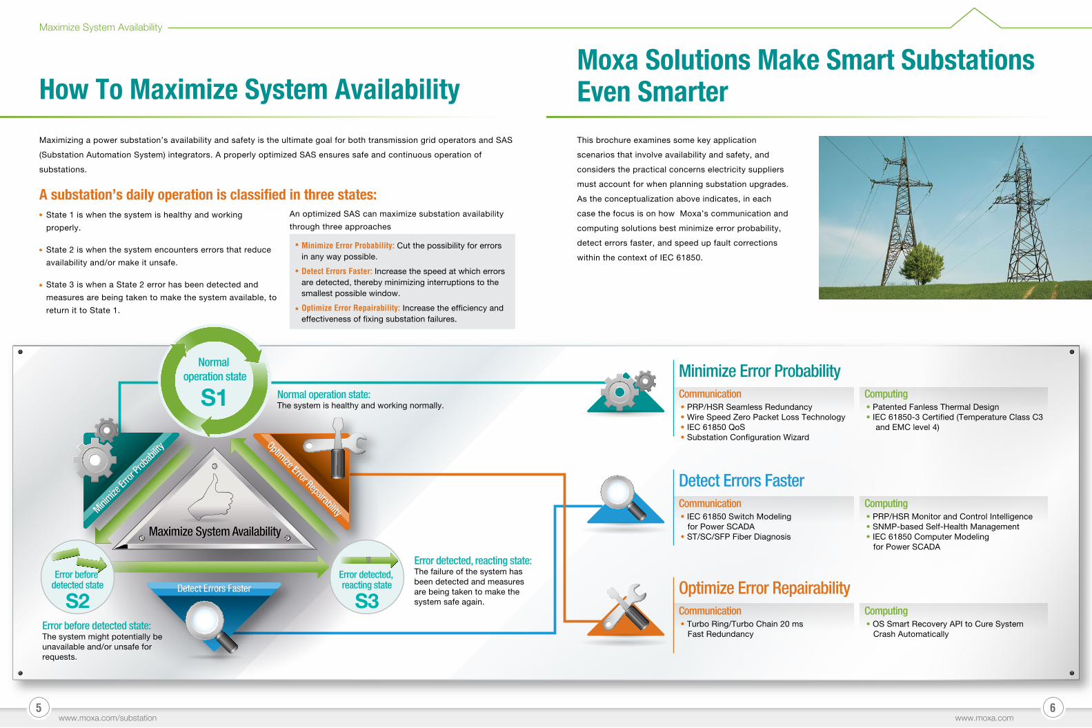
Normal operation state: The system is healthy and working normally.
Error before detected state: The system might potentially be unavailable and/or unsafe for requests.
S1
Normal operation state
Maximize System AvailabilityMaximize System Availability
S2Error before
detected state
S3Error detected, reacting state
Optimize Error Repairability
Optimize Error RepairabilityMinimize
Error
Prob
abilit
y
Minimize
Error
Prob
abilit
y
Detect Errors FasterDetect Errors Faster
Communication• PRP/HSR Seamless Redundancy• Wire Speed Zero Packet Loss Technology• IEC 61850 QoS• Substation Configuration Wizard
Computing• Patented Fanless Thermal Design• IEC 61850-3 Certified (Temperature Class C3 and EMC level 4)
Minimize Error Probability
Communication• IEC 61850 Switch Modeling for Power SCADA• ST/SC/SFP Fiber Diagnosis
Computing• PRP/HSR Monitor and Control Intelligence• SNMP-based Self-Health Management• IEC 61850 Computer Modeling for Power SCADA
Detect Errors Faster
Communication• Turbo Ring/Turbo Chain 20 ms Fast Redundancy
Computing• OS Smart Recovery API to Cure System Crash Automatically
Optimize Error Repairability
Error detected, reacting state: The failure of the system has been detected and measures are being taken to make the system safe again.
How To Maximize System AvailabilityMoxa Solutions Make Smart Substations Even Smarter
Maximizing a power substation’s availability and safety is the ultimate goal for both transmission grid operators and SAS
(Substation Automation System) integrators. A properly optimized SAS ensures safe and continuous operation of
substations.
State 1 is when the system is healthy and working
properly.
State 2 is when the system encounters errors that reduce
availability and/or make it unsafe.
State 3 is when a State 2 error has been detected and
measures are being taken to make the system available, to
return it to State 1.
A substation’s daily operation is classified in three states:
Minimize Error Probability: Cut the possibility for errors in any way possible.
Detect Errors Faster: Increase the speed at which errors are detected, thereby minimizing interruptions to the smallest possible window.
Optimize Error Repairability: Increase the efficiency and effectiveness of fixing substation failures.
This brochure examines some key application
scenarios that involve availability and safety, and
considers the practical concerns electricity suppliers
must account for when planning substation upgrades.
As the conceptualization above indicates, in each
case the focus is on how Moxa’s communication and
computing solutions best minimize error probability,
detect errors faster, and speed up fault corrections
within the context of IEC 61850.
www.moxa.com/substation
Maximize System Availability
www.moxa.com
An optimized SAS can maximize substation availability
through three approaches
87
Moxa Solutions Make Smart Substations Even Smarter
Minimize Error Probability
www.moxa.com/substation www.moxa.com
IEC 61850-3 Compliant
Level 4 EMC, for stronger protection against electrical interference
-40 to 75°C ambient temperature tolerance
High tolerances for constant vibrations and shocks
PRP/HSR Standardized Protocols for Zero Recovery Time
Substation automation devices must communicate
critical, low-level IEC 61850 multicasts (GOOSE/SMV)
with the highest priority, without fail. Prioritizing the
transmission of GOOSE/SMV packets guarantees that
these messages are clearly received without distortion
throughout the entire network, regardless of what other
communications may be currently congesting the lines.
Ping-based solutions are not sufficient to achieve this.
To fully satisfy IEEE 1613 Class 2 requirements,
substation switches must support strong QoS traffic
shaping.
Critical packets can be prioritized in different levels
Packet types: GOOSE, SMV, PTP
Packet priorities: High, medium, normal, low
IEC 61850 QoS: Substation Automation Packet Priority
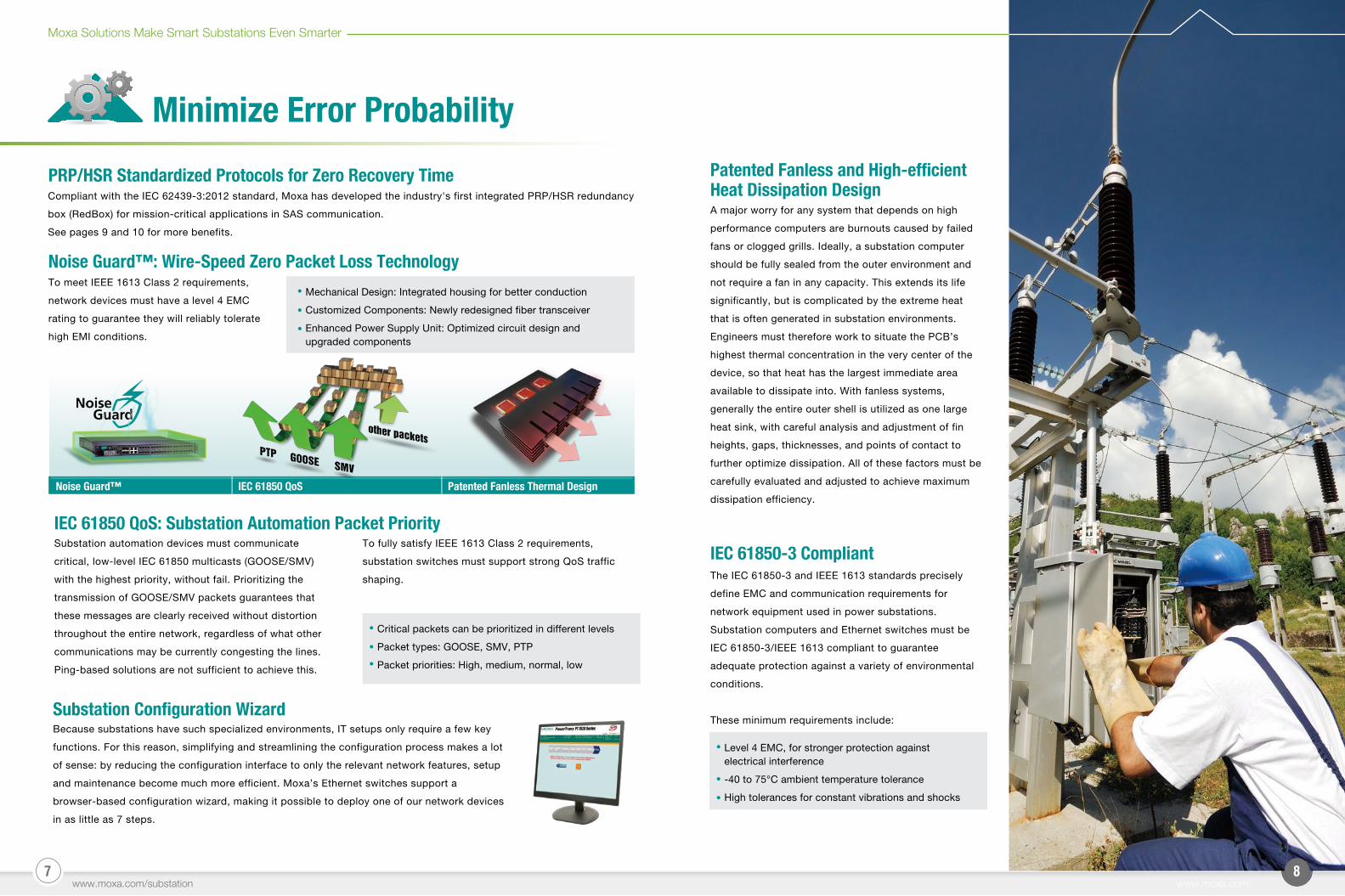
Patented Fanless and High-efficient Heat Dissipation Design
Noise Guard™: Wire-Speed Zero Packet Loss Technology
Mechanical Design: Integrated housing for better conduction
Customized Components: Newly redesigned fiber transceiver
Enhanced Power Supply Unit: Optimized circuit design and upgraded components
Compliant with the IEC 62439-3:2012 standard, Moxa has developed the industry's first integrated PRP/HSR redundancy
box (RedBox) for mission-critical applications in SAS communication.
See pages 9 and 10 for more benefits.
A major worry for any system that depends on high
performance computers are burnouts caused by failed
fans or clogged grills. Ideally, a substation computer
should be fully sealed from the outer environment and
not require a fan in any capacity. This extends its life
significantly, but is complicated by the extreme heat
that is often generated in substation environments.
Engineers must therefore work to situate the PCB’s
highest thermal concentration in the very center of the
device, so that heat has the largest immediate area
available to dissipate into. With fanless systems,
generally the entire outer shell is utilized as one large
heat sink, with careful analysis and adjustment of fin
heights, gaps, thicknesses, and points of contact to
further optimize dissipation. All of these factors must be
carefully evaluated and adjusted to achieve maximum
dissipation efficiency.Patented Fanless Thermal DesignNoise Guard™ IEC 61850 QoS
The IEC 61850-3 and IEEE 1613 standards precisely
define EMC and communication requirements for
network equipment used in power substations.
Substation computers and Ethernet switches must be
IEC 61850-3/IEEE 1613 compliant to guarantee
adequate protection against a variety of environmental
conditions.
These minimum requirements include:
To meet IEEE 1613 Class 2 requirements,
network devices must have a level 4 EMC
rating to guarantee they will reliably tolerate
high EMI conditions.
Substation Configuration WizardBecause substations have such specialized environments, IT setups only require a few key
functions. For this reason, simplifying and streamlining the configuration process makes a lot
of sense: by reducing the configuration interface to only the relevant network features, setup
and maintenance become much more efficient. Moxa’s Ethernet switches support a
browser-based configuration wizard, making it possible to deploy one of our network devices
in as little as 7 steps.
9 10www.moxa.com
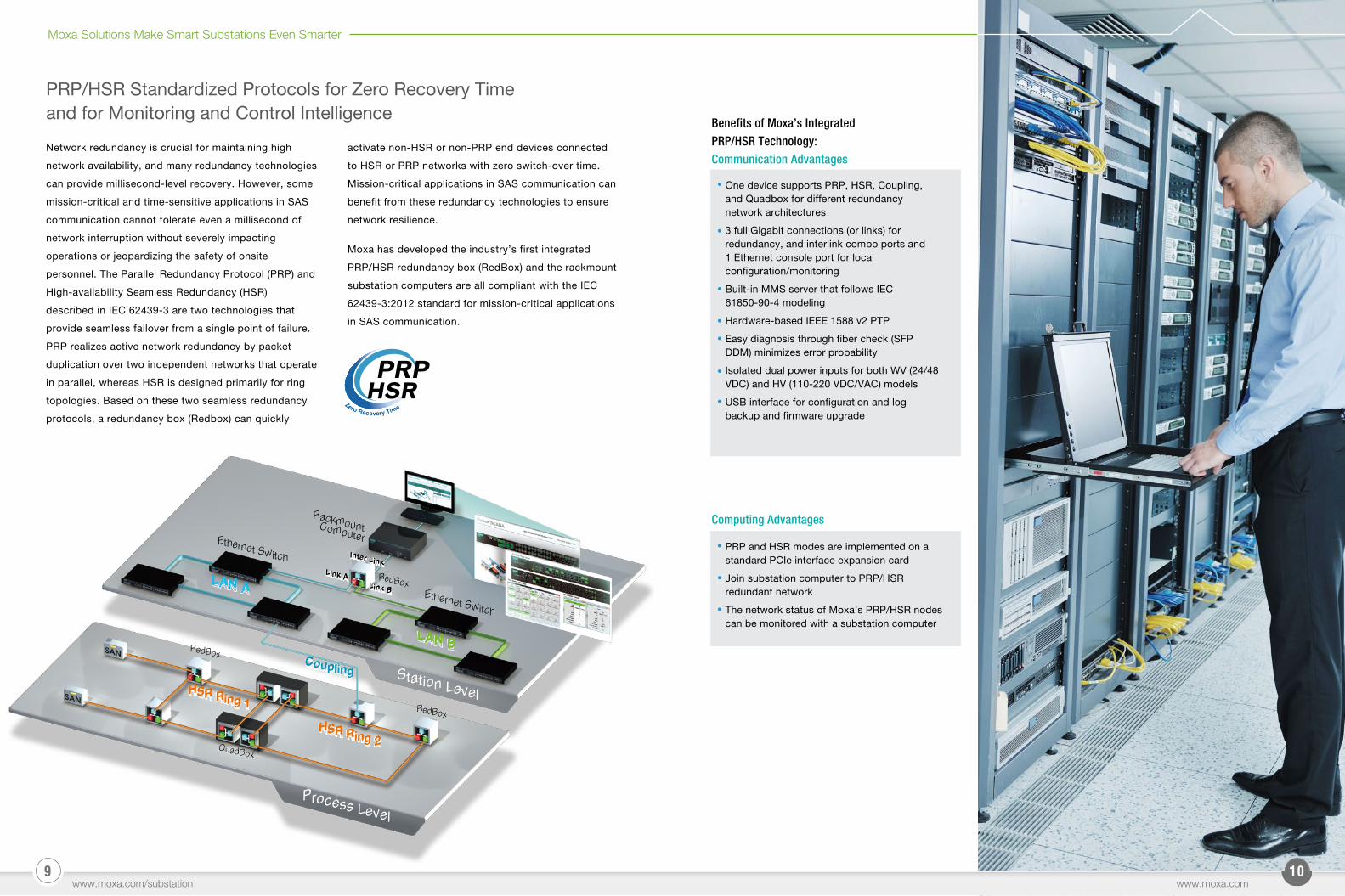
PRP/HSR Standardized Protocols for Zero Recovery Time and for Monitoring and Control Intelligence
www.moxa.com/substation
Moxa Solutions Make Smart Substations Even Smarter
One device supports PRP, HSR, Coupling, and Quadbox for different redundancy network architectures
3 full Gigabit connections (or links) for redundancy, and interlink combo ports and 1 Ethernet console port for local configuration/monitoring
Built-in MMS server that follows IEC 61850-90-4 modeling
Hardware-based IEEE 1588 v2 PTP
Easy diagnosis through fiber check (SFP DDM) minimizes error probability
Isolated dual power inputs for both WV (24/48 VDC) and HV (110-220 VDC/VAC) models
USB interface for configuration and log backup and firmware upgrade
Benefits of Moxa’s Integrated PRP/HSR Technology:Communication Advantages
PRP and HSR modes are implemented on a standard PCIe interface expansion card
Join substation computer to PRP/HSR redundant network
The network status of Moxa’s PRP/HSR nodes can be monitored with a substation computer
Computing Advantages
Ethernet Switch
Ethernet Switch
LAN B
LAN A
LAN B
LAN A
RackmountComputer
RedBox
RedBox
QuadBox
Coupling
HSR Ring 1
HSR Ring 2
Coupling Station Level
Process Level
HSR Ring 1
HSR Ring 2
Inter LinkLink A
Link B
Inter Link
RedBoxLink A
Link B
Network redundancy is crucial for maintaining high
network availability, and many redundancy technologies
can provide millisecond-level recovery. However, some
mission-critical and time-sensitive applications in SAS
communication cannot tolerate even a millisecond of
network interruption without severely impacting
operations or jeopardizing the safety of onsite
personnel. The Parallel Redundancy Protocol (PRP) and
High-availability Seamless Redundancy (HSR)
described in IEC 62439-3 are two technologies that
provide seamless failover from a single point of failure.
PRP realizes active network redundancy by packet
duplication over two independent networks that operate
in parallel, whereas HSR is designed primarily for ring
topologies. Based on these two seamless redundancy
protocols, a redundancy box (Redbox) can quickly
activate non-HSR or non-PRP end devices connected
to HSR or PRP networks with zero switch-over time.
Mission-critical applications in SAS communication can
benefit from these redundancy technologies to ensure
network resilience.
Moxa has developed the industry’s first integrated
PRP/HSR redundancy box (RedBox) and the rackmount
substation computers are all compliant with the IEC
62439-3:2012 standard for mission-critical applications
in SAS communication.
1211
Detect Errors Faster
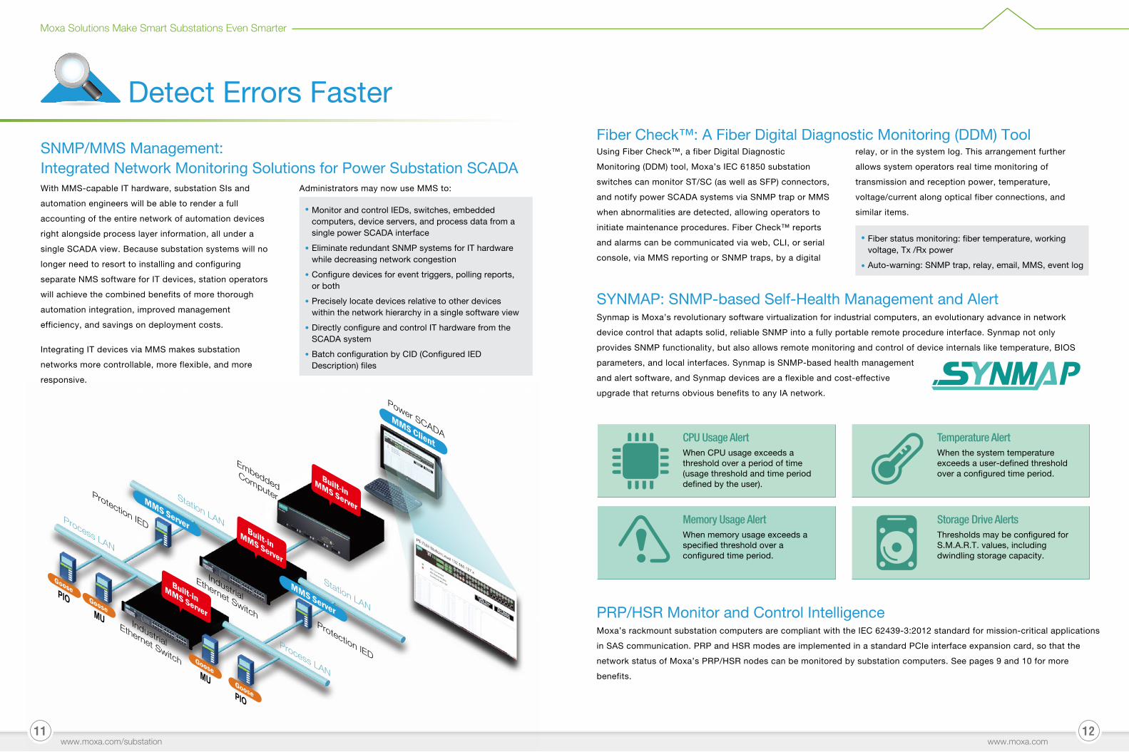
SNMP/MMS Management: Integrated Network Monitoring Solutions for Power Substation SCADA
www.moxa.com
With MMS-capable IT hardware, substation SIs and
automation engineers will be able to render a full
accounting of the entire network of automation devices
right alongside process layer information, all under a
single SCADA view. Because substation systems will no
longer need to resort to installing and configuring
separate NMS software for IT devices, station operators
will achieve the combined benefits of more thorough
automation integration, improved management
efficiency, and savings on deployment costs.
Integrating IT devices via MMS makes substation
networks more controllable, more flexible, and more
responsive.
SYNMAP: SNMP-based Self-Health Management and Alert
CPU Usage AlertWhen CPU usage exceeds a threshold over a period of time (usage threshold and time period defined by the user).
Temperature AlertWhen the system temperature exceeds a user-defined threshold over a configured time period.
Memory Usage AlertWhen memory usage exceeds a specified threshold over a configured time period.
Storage Drive AlertsThresholds may be configured for S.M.A.R.T. values, including dwindling storage capacity.
Synmap is Moxa’s revolutionary software virtualization for industrial computers, an evolutionary advance in network
device control that adapts solid, reliable SNMP into a fully portable remote procedure interface. Synmap not only
provides SNMP functionality, but also allows remote monitoring and control of device internals like temperature, BIOS
parameters, and local interfaces. Synmap is SNMP-based health management
and alert software, and Synmap devices are a flexible and cost-effective
upgrade that returns obvious benefits to any IA network.
PRP/HSR Monitor and Control IntelligenceMoxa’s rackmount substation computers are compliant with the IEC 62439-3:2012 standard for mission-critical applications
in SAS communication. PRP and HSR modes are implemented in a standard PCIe interface expansion card, so that the
network status of Moxa’s PRP/HSR nodes can be monitored by substation computers. See pages 9 and 10 for more
benefits.
Monitor and control IEDs, switches, embedded computers, device servers, and process data from a single power SCADA interface
Eliminate redundant SNMP systems for IT hardware while decreasing network congestion
Configure devices for event triggers, polling reports, or both
Precisely locate devices relative to other devices within the network hierarchy in a single software view
Directly configure and control IT hardware from the SCADA system
Batch configuration by CID (Configured IED Description) files
Using Fiber Check™, a fiber Digital Diagnostic
Monitoring (DDM) tool, Moxa’s IEC 61850 substation
switches can monitor ST/SC (as well as SFP) connectors,
and notify power SCADA systems via SNMP trap or MMS
when abnormalities are detected, allowing operators to
initiate maintenance procedures. Fiber Check™ reports
and alarms can be communicated via web, CLI, or serial
console, via MMS reporting or SNMP traps, by a digital
relay, or in the system log. This arrangement further
allows system operators real time monitoring of
transmission and reception power, temperature,
voltage/current along optical fiber connections, and
similar items.
Fiber status monitoring: fiber temperature, working voltage, Tx /Rx power
Auto-warning: SNMP trap, relay, email, MMS, event log
Fiber Check™: A Fiber Digital Diagnostic Monitoring (DDM) Tool
Moxa Solutions Make Smart Substations Even Smarter
www.moxa.com/substation
MMS Client
Built-in MMS Server
Built-in MMS Server
Built-in MMS ServerMMS Server
MMS Server
Goose
Goose
Goose
Goose
Power SCADA
EmbeddedComputer
Protection IED
Protection IED
Industrial
Ethernet Switch
Industrial
Ethernet Switch
PIO
PIOMU
MU
Station LAN
Station LAN
Process LAN
Process LAN
Administrators may now use MMS to:
Gigabit Backbone
Gigabit BackboneGigabit Uplink
Gigabit Uplink
Megabit Uplink
IEDIED
IED
IED
IEDIED
IEDIED
13 14
Optimize Error Repairability OS Smart Recovery:Remotely or Automatically Trigger a Computer to Restore its Entire Software Environment
www.moxa.com/substation www.moxa.com
Power Shutdown: Auto boot up
System slowdowns: Configure period recoveries to speed things up
Bootable but damaged systems: Configure a rewrite procedure that will let you know if the damage is in hardware or software
System crash and boot failure: Use auto-recovery to verify if it’s hardware or software, and resurrect the machine if it’s a software problem
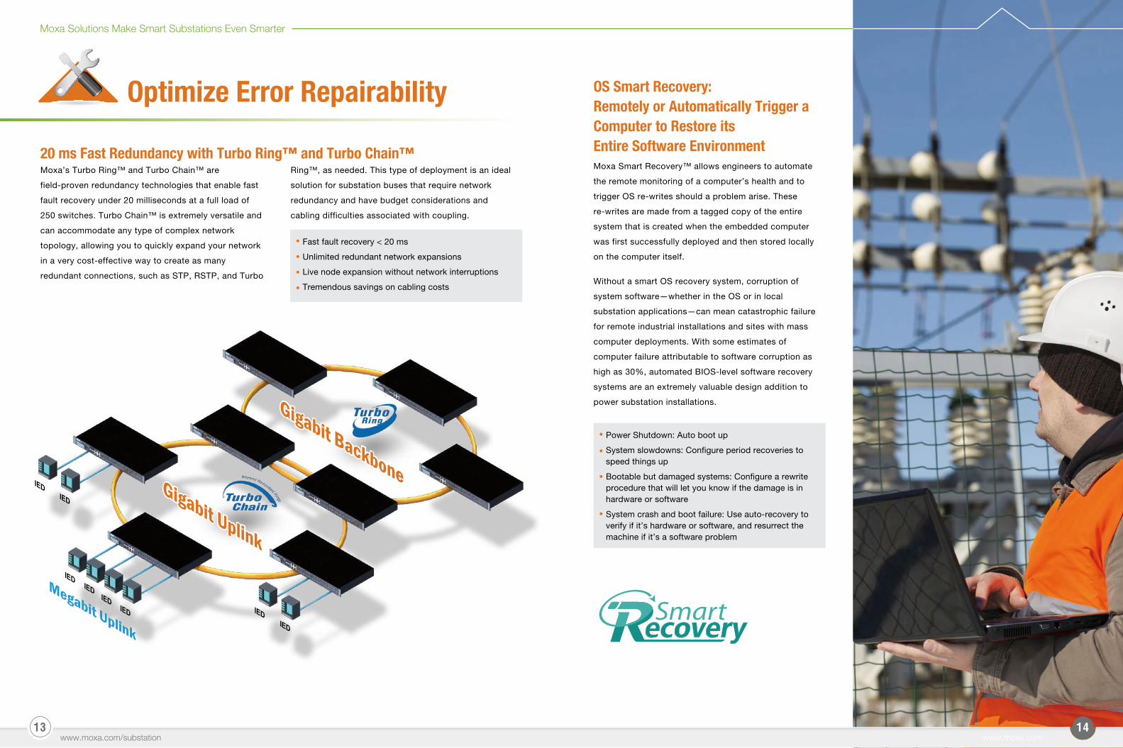
Fast fault recovery < 20 ms
Unlimited redundant network expansions
Live node expansion without network interruptions
Tremendous savings on cabling costs
Moxa Smart Recovery™ allows engineers to automate
the remote monitoring of a computer’s health and to
trigger OS re-writes should a problem arise. These
re-writes are made from a tagged copy of the entire
system that is created when the embedded computer
was first successfully deployed and then stored locally
on the computer itself.
Without a smart OS recovery system, corruption of
system software—whether in the OS or in local
substation applications—can mean catastrophic failure
for remote industrial installations and sites with mass
computer deployments. With some estimates of
computer failure attributable to software corruption as
high as 30%, automated BIOS-level software recovery
systems are an extremely valuable design addition to
power substation installations.
20 ms Fast Redundancy with Turbo Ring™ and Turbo Chain™Moxa’s Turbo Ring™ and Turbo Chain™ are
field-proven redundancy technologies that enable fast
fault recovery under 20 milliseconds at a full load of
250 switches. Turbo Chain™ is extremely versatile and
can accommodate any type of complex network
topology, allowing you to quickly expand your network
in a very cost-effective way to create as many
redundant connections, such as STP, RSTP, and Turbo
Ring™, as needed. This type of deployment is an ideal
solution for substation buses that require network
redundancy and have budget considerations and
cabling difficulties associated with coupling.
Moxa Solutions Make Smart Substations Even Smarter
1615www.moxa.com/substation
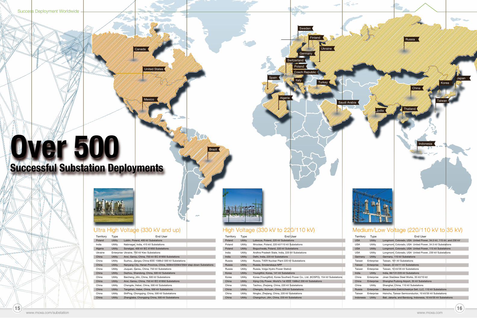
Success Deployment Worldwide
www.moxa.com
Poland
India
Algeria
Ukraine
China
China
China
China
China
China
China
China
China
China
China
Utility
Utility
Utility
Enterprise
Utility
Utility
Utility
Utility
Utility
Utility
Utility
Utility
Utility
Utility
Utility
Lublin, Poland, 400 kV Substations
Nabinagar, India, 415 kV Substations
Sonelgaz, 400 kV IEC 61850 Substations
Ukraine, 750 kV Kiev Substations
Anxi, Gansu, China, 750 kV IEC 61850 Substations
Suzhou, Jiangsu China IEEE 1588v2 500 kV Substations
Nanyang City, Henan Province, China, 500kV/220kV/35kV step-down Substations
Jiuquan, Gansu, China, 750 kV Substations
Dezhou, Shandong, China, 500 kV Substations
Baicheng, Jilin, China, 500 kV Substations
Anxi, Gansu, China, 750 kV IEC 61850 Substations
Chengde, Hebei, China, 500 kV Substations
Tangshan, Hebei, China, 500 kV Substations
ShiPing, Chongqing, China, 500 kV Substations
Zhangjiaba, Chongqing China, 500 kV Substations
Territory Type End UserPoland
Poland
Poland
India
India
Russia
Russia
Russia
Korea
Korea
China
China
China
China
China
Utility
Utility
Utility
Utility
Utility
Utility
Utility
Utility
Utility
Utility
Utility
Utility
Utility
Utility
Utility
Lubocza, Poland, 220 kV Substations
Wrocław, Poland, 220 kV/110 kV Substations
Boguchwała, Poland, 220 kV Substations
Andhra Pradesh State, India, 220 kV Substations
Delhi, India, 220 kV Substations
Russia, TVER Nuclear Plant 220 kV Substations
Russia, Smolenskaya NPP
Russia, Volga Hydro Power Station
YoungWol, Korea, 141 kV Substations
Korea (YoungWol), Korea Southern Power Co., Ltd. (KOSPO), 154 kV Substations
Xijing City Power, World’s 1st IEEE 1588v2 200 kV Substations
Taizhou, Zhejiang, China, 220 kV Substations
Chengdu, Sichuan, China, 220 kV Substations
Ningbo, Zhejiang, China, 220 kV Substations
Changchun, Jilin, China, 220 kV Substations
Territory Type End User Territory Type End UserUSA
USA
USA
USA
Germany
Taiwan
Taiwan
Taiwan
India
China
China
China
Russia
Taiwan
Indonesia
Utility
Utility
Utility
Utility
Utility
Enterprise
Enterprise
Enterprise
Utility
Enterprise
Enterprise
Utility
Enterprise
Enterprise
Utility
Longmont, Colorado, USA United Power, 34.5 kV, 115 kV, and 230 kV
Longmont, Colorado, USA United Power, 34.5 kV Substations
Longmont, Colorado, USA United Power, 115 kV Substations
Longmont, Colorado, USA United Power, 230 kV Substations
Germany, 110 kV Substations
Taiwan, 161 kV Substations
Taiwan, 22 kV/11 kV Substations
Taiwan, 10 kV/35 kV Substations
India, 66/131/220 kV Substations
Jinan Stainless Steel Works, 35 kV/10 kV
Shanghai Pudong Airport, 35 kV Substations
Shanghai, China, 110 kV Substations
Berezovskie Elektricheskiye Seti, LLC. 110 kV Substations
Hsinchu, Taiwan Semiconductor, 10 kV/35 kV Substations
Bali, Jakarta, and Bandung, Indonesia, 10 kV/35 kV Substations
Medium/Low Voltage (220/110 kV to 35 kV)Ultra High Voltage (330 kV and up) High Voltage (330 kV to 220/110 kV)
Canada
Mexico
Brazil
United States
Sweden
Finland Russia
Japan
Korea
Taiwan
Indonesia
Spain
Algeria
Saudi Arabia
Germany
Ukraine
Poland
Czech Republic
Italy
India
China
Thailand
Turkey
Switzerland
Over 500 Successful Substation Deployments
1817www.moxa.com/substation
Product Selection Guide
www.moxa.com
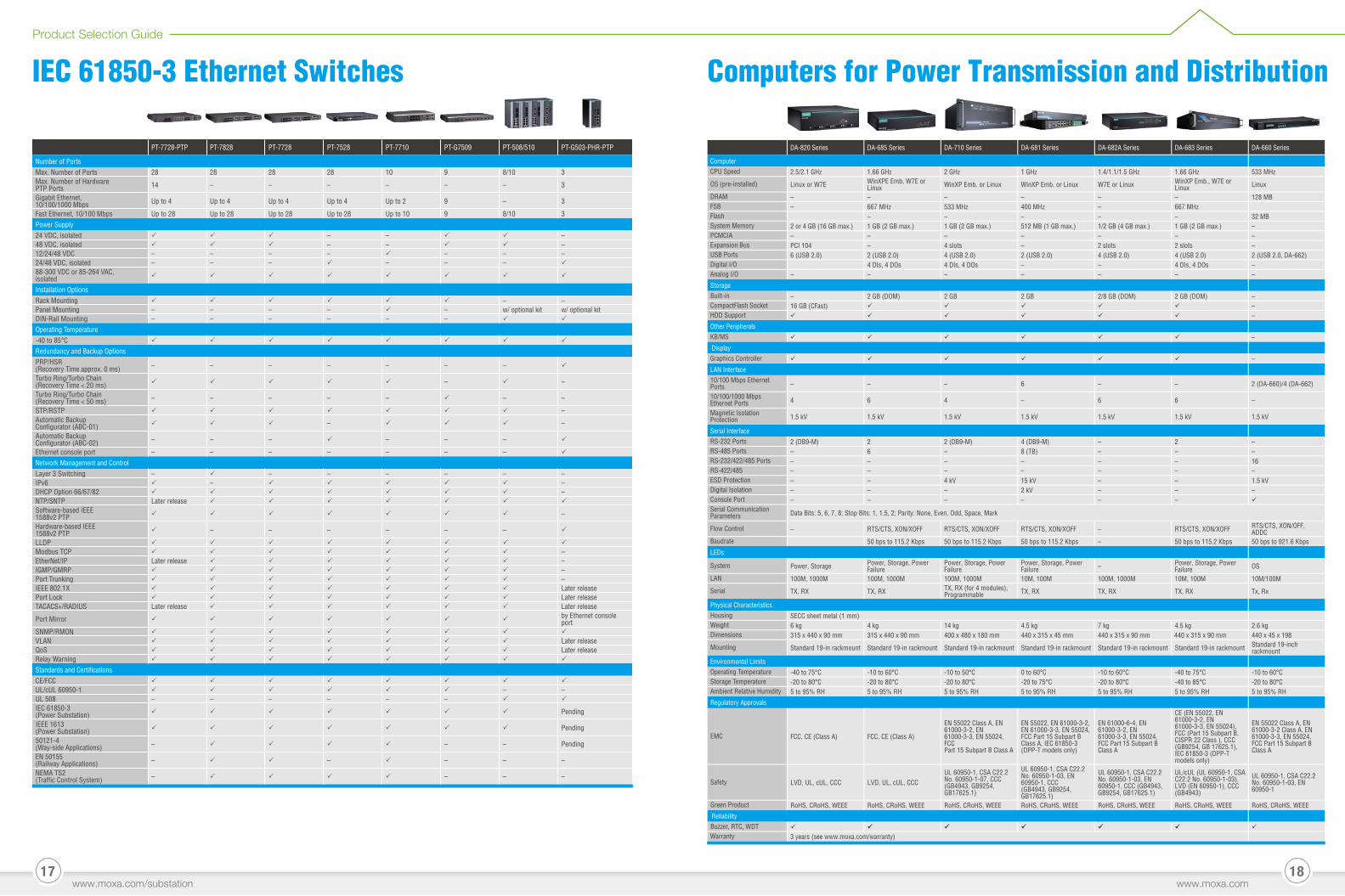
PT-7728-PTP PT-7828 PT-7728 PT-7528 PT-7710 PT-G7509 PT-508/510 PT-G503-PHR-PTP
Number of PortsMax. Number of Ports 28 28 28 28 10 9 8/10 3Max. Number of Hardware PTP Ports 14 – – – – – – 3
Gigabit Ethernet, 10/100/1000 Mbps Up to 4 Up to 4 Up to 4 Up to 4 Up to 2 9 – 3
Fast Ethernet, 10/100 Mbps Up to 28 Up to 28 Up to 28 Up to 28 Up to 10 9 8/10 3Power Supply24 VDC, isolated – – –48 VDC, isolated – – –12/24/48 VDC – – – – – – –24/48 VDC, isolated – – – – – –88-300 VDC or 85-264 VAC, isolatedInstallation OptionsRack Mounting – –Panel Mounting – – – – – w/ optional kit w/ optional kitDIN-Rail Mounting – – – – – –Operating Temperature-40 to 85°CRedundancy and Backup OptionsPRP/HSR (Recovery Time approx. 0 ms) – – – – – – –
Turbo Ring/Turbo Chain (Recovery Time < 20 ms) – –
Turbo Ring/Turbo Chain (Recovery Time < 50 ms) – – – – – – –
STP/RSTP –Automatic Backup Confi gurator (ABC-01) – –
Automatic Backup Confi gurator (ABC-02) – – – – – –
Ethernet console port – – – – – – –Network Management and ControlLayer 3 Switching – – – – – – –IPv6 – –DHCP Option 66/67/82 –NTP/SNTP Later releaseSoftware-based IEEE 1588v2 PTP –
Hardware-based IEEE 1588v2 PTP – – – – – –
LLDPModbus TCP –EtherNet/IP Later release –IGMP/GMRP –Port Trunking –IEEE 802.1X Later releasePort Lock Later releaseTACACS+/RADIUS Later release Later release
Port Mirror by Ethernet console port
SNMP/RMONVLAN Later releaseQoS Later releaseRelay WarningStandards and Certifi cationsCE/FCCUL/cUL 60950-1 – –UL 508 – – – – – –IEC 61850-3 (Power Substation) Pending
IEEE 1613 (Power Substation) Pending
50121-4 (Way-side Applications) – – – Pending
EN 50155 (Railway Applications) – – – – –
NEMA TS2 (Traffi c Control System) – – – –
IEC 61850-3 Ethernet Switches Computers for Power Transmission and Distribution
DA-820 Series DA-685 Series DA-710 Series DA-681 Series DA-682A Series DA-683 Series DA-660 Series
ComputerCPU Speed 2.5/2.1 GHz 1.66 GHz 2 GHz 1 GHz 1.4/1.1/1.5 GHz 1.66 GHz 533 MHz
OS (pre-installed) Linux or W7E WinXPE Emb, W7E or Linux WinXP Emb. or Linux WinXP Emb. or Linux W7E or Linux WinXP Emb., W7E or
Linux Linux
DRAM – – – – – – 128 MBFSB – 667 MHz 533 MHz 400 MHz – 667 MHzFlash – – – – – 32 MBSystem Memory 2 or 4 GB (16 GB max.) 1 GB (2 GB max.) 1 GB (2 GB max.) 512 MB (1 GB max.) 1/2 GB (4 GB max.) 1 GB (2 GB max.) –PCMCIA – – – – – – –Expansion Bus PCI 104 – 4 slots – 2 slots 2 slots –USB Ports 6 (USB 2.0) 2 (USB 2.0) 4 (USB 2.0) 2 (USB 2.0) 4 (USB 2.0) 4 (USB 2.0) 2 (USB 2.0, DA-662)Digital I/O 4 DIs, 4 DOs 4 DIs, 4 DOs – – 4 DIs, 4 DOs –Analog I/O – – – – – – –
StorageBuilt-in – 2 GB (DOM) 2 GB 2 GB 2/8 GB (DOM) 2 GB (DOM) –CompactFlash Socket 16 GB (CFast) –HDD Support –
Other PeripheralsKB/MS –
DisplayGraphics Controller –
LAN Interface10/100 Mbps Ethernet Ports – – – 6 – – 2 (DA-660)/4 (DA-662)
10/100/1000 Mbps Ethernet Ports 4 6 4 – 6 6 –
Magnetic Isolation Protection 1.5 kV 1.5 kV 1.5 kV 1.5 kV 1.5 kV 1.5 kV 1.5 kV
Serial InterfaceRS-232 Ports 2 (DB9-M) 2 2 (DB9-M) 4 (DB9-M) – 2 –RS-485 Ports – 6 – 8 (TB) – – –RS-232/422/485 Ports – – – – – – 16RS-422/485 – – – – – – –ESD Protection – – 4 kV 15 kV – – 1.5 kVDigital Isolation – – – 2 kV – – –Console Port – – – – – –Serial Communication Parameters Data Bits: 5, 6, 7, 8; Stop Bits: 1, 1.5, 2; Parity: None, Even, Odd, Space, Mark
Flow Control – RTS/CTS, XON/XOFF RTS/CTS, XON/XOFF RTS/CTS, XON/XOFF – RTS/CTS, XON/XOFF RTS/CTS, XON/OFF, ADDC
Baudrate 50 bps to 115.2 Kbps 50 bps to 115.2 Kbps 50 bps to 115.2 Kbps – 50 bps to 115.2 Kbps 50 bps to 921.6 Kbps
LEDs
System Power, Storage Power, Storage, Power Failure
Power, Storage, Power Failure
Power, Storage, Power Failure – Power, Storage, Power
Failure OS
LAN 100M, 1000M 100M, 1000M 100M, 1000M 10M, 100M 100M, 1000M 10M, 100M 10M/100M
Serial TX, RX TX, RX TX, RX (for 4 modules), Programmable TX, RX TX, RX TX, RX Tx, Rx
Physical CharacteristicsHousing SECC sheet metal (1 mm)Weight 6 kg 4 kg 14 kg 4.5 kg 7 kg 4.5 kg 2.6 kgDimensions 315 x 440 x 90 mm 315 x 440 x 90 mm 400 x 480 x 180 mm 440 x 315 x 45 mm 440 x 315 x 90 mm 440 x 315 x 90 mm 440 x 45 x 198
Mounting Standard 19-in rackmount Standard 19-in rackmount Standard 19-in rackmount Standard 19-in rackmount Standard 19-in rackmount Standard 19-in rackmount Standard 19-inch rackmount
Environmental LimitsOperating Temperature -40 to 75°C -10 to 60°C -10 to 50°C 0 to 60°C -10 to 60°C -40 to 75°C -10 to 60°CStorage Temperature -20 to 80°C -20 to 80°C -20 to 80°C -20 to 75°C -20 to 80°C -40 to 85°C -20 to 80°CAmbient Relative Humidity 5 to 95% RH 5 to 95% RH 5 to 95% RH 5 to 95% RH 5 to 95% RH 5 to 95% RH 5 to 95% RH
Regulatory Approvals
EMC FCC, CE (Class A) FCC, CE (Class A)
EN 55022 Class A, EN 61000-3-2, EN 61000-3-3, EN 55024, FCCPart 15 Subpart B Class A
EN 55022, EN 61000-3-2, EN 61000-3-3, EN 55024, FCC Part 15 Subpart B Class A, IEC 61850-3 (DPP-T models only)
EN 61000-6-4, EN 61000-3-2, EN 61000-3-3, EN 55024, FCC Part 15 Subpart B Class A
CE (EN 55022, EN 61000-3-2, EN 61000-3-3, EN 55024), FCC (Part 15 Subpart B, CISPR 22 Class ), CCC (GB9254, GB 17625.1), IEC 61850-3 (DPP-T models only)
EN 55022 Class A, EN 61000-3-2 Class A, EN 61000-3-3, EN 55024, FCC Part 15 Subpart B Class A
Safety LVD, UL, cUL, CCC LVD, UL, cUL, CCCUL 60950-1, CSA C22.2 No. 60950-1-07, CCC (GB4943, GB9254, GB17625.1)
UL 60950-1, CSA C22.2 No. 60950-1-03, EN 60950-1, CCC(GB4943, GB9254, GB17625.1)
UL 60950-1, CSA C22.2 No. 60950-1-03, EN 60950-1, CCC (GB4943, GB9254, GB17625.1)
UL/cUL (UL 60950-1, CSA C22.2 No. 60950-1-03), LVD (EN 60950-1), CCC (GB4943)
UL 60950-1, CSA C22.2 No. 60950-1-03, EN 60950-1
Green Product RoHS, CRoHS, WEEE RoHS, CRoHS, WEEE RoHS, CRoHS, WEEE RoHS, CRoHS, WEEE RoHS, CRoHS, WEEE RoHS, CRoHS, WEEE RoHS, CRoHS, WEEE
ReliabilityBuzzer, RTC, WDTWarranty 3 years (see www.moxa.com/warranty)
Recommended