Relion® Protection and control
650 seriesIEC 61850 Communication Protocol Manual


Document ID: 1MRK 511 242-UENIssued: February 2011
Revision: -Product version: 1.1
© Copyright 2011 ABB. All rights reserved
CopyrightThis document and parts thereof must not be reproduced or copied without writtenpermission from ABB, and the contents thereof must not be imparted to a thirdparty, nor used for any unauthorized purpose.
The software or hardware described in this document is furnished under a licenseand may be used or disclosed only in accordance with the terms of such license.
TrademarksABB and Relion are registered trademarks of ABB Group. All other brand orproduct names mentioned in this document may be trademarks or registeredtrademarks of their respective holders.
WarrantyPlease inquire about the terms of warranty from your nearest ABB representative.
ABB AB
Substation Automation Products
SE-721 59 Västerås
Sweden
Telephone: +46 (0) 21 32 50 00
Facsimile: +46 (0) 21 14 69 18
http://www.abb.com/substationautomation
DisclaimerThe data, examples and diagrams in this manual are included solely for the conceptor product description and are not to be deemed as a statement of guaranteedproperties. All persons responsible for applying the equipment addressed in thismanual must satisfy themselves that each intended application is suitable andacceptable, including that any applicable safety or other operational requirementsare complied with. In particular, any risks in applications where a system failure and/or product failure would create a risk for harm to property or persons (including butnot limited to personal injuries or death) shall be the sole responsibility of theperson or entity applying the equipment, and those so responsible are herebyrequested to ensure that all measures are taken to exclude or mitigate such risks.
This document has been carefully checked by ABB but deviations cannot becompletely ruled out. In case any errors are detected, the reader is kindly requestedto notify the manufacturer. Other than under explicit contractual commitments, inno event shall ABB be responsible or liable for any loss or damage resulting fromthe use of this manual or the application of the equipment.

ConformityThis product complies with the directive of the Council of the EuropeanCommunities on the approximation of the laws of the Member States relating toelectromagnetic compatibility (EMC Directive 2004/108/EC) and concerningelectrical equipment for use within specified voltage limits (Low-voltage directive2006/95/EC). This conformity is the result of tests conducted by ABB inaccordance with the product standards EN 50263 and EN 60255-26 for the EMCdirective, and with the product standards EN 60255-1 and EN 60255-27 for the lowvoltage directive. The IED is designed in accordance with the internationalstandards of the IEC 60255 series.

Table of contents
Section 1 Introduction.......................................................................7This manual........................................................................................7Intended audience..............................................................................7Product documentation.......................................................................8
Product documentation set............................................................8Document revision history.............................................................9Related documents........................................................................9
Symbols and conventions.................................................................11Safety indication symbols............................................................11Manual conventions.....................................................................11Functions included in 650 series IEDs........................................12
Section 2 Introduction to IEC 61850...............................................19Related documentation to IEC 61850..........................................20
Section 3 Substation Configuration description Language(SCL)..............................................................................23The substation section......................................................................24The communication section..............................................................24The IED section................................................................................25Tool concept.....................................................................................28Engineering concept in IEC 61850-6................................................29
Section 4 Communication profile....................................................31
Section 5 Supported services.........................................................33
Section 6 Data sets and control blocks..........................................37Data sets..........................................................................................37Report control block (URCB/BRCB).................................................38GOOSE Control Blocks (GoCB).......................................................41
Section 7 Logical node data model................................................45Common data objects in each logical node......................................45Logical nodes for automatic control..................................................46
Automatic tap changer control ATCC..........................................46Automatic voltage control for tapchanger, parallelcontrol TR8ATCC...................................................................46Tap changer control and supervision, 6 binary inputsTCMYLTC..............................................................................58
Logical nodes for control..................................................................60
Table of contents
650 series 1Communication Protocol Manual

Bay control CBAY........................................................................60Apparatus control QCBAY......................................................60
Interlocking CILO.........................................................................62Interlocking SCILO.................................................................62
Switch controller CSWI................................................................63Apparatus control SCSWI......................................................63
Logical nodes for conversion functions............................................65Integer to Boolean converter FCVB.............................................65
Integer to Boolean 16 conversion with Logic Noderepresentation IB16FCVB......................................................65
Boolean to integer converter FCVI..............................................66Boolean 16 to Integer conversion with Logic Noderepresentation B16IFCVI........................................................66
Logical nodes for protection functions..............................................67Differential protection PDIF.........................................................67
Transformer differential protection, two windingT2WPDIF................................................................................67Transformer differential protection, three windingT3WPDIF................................................................................69Restricted earth fault protection, low impedanceREFPDIF................................................................................71Generator differential protection GENPDIF............................721 Ph High impedance differential protection HZPDIF.............75
Distance protection PDIS............................................................76Five zone distance protection, quadrilateralcharacteristic ZQDPDIS.........................................................76Phase selection with load enchroachment, quadrilateralcharacteristic FDPSPDIS.......................................................80Five zone distance protection, mho characteristicZMOPDIS...............................................................................83Faulty phase identification with load enchroachment formho FMPSPDIS.....................................................................87Underimpedance protection for generator andtransformer ZGPDIS...............................................................88Loss of exectation LEXPDIS..................................................91Faulty phase identification with load enchroachment formho LEPDIS...........................................................................92
Directional overpower PDOP.......................................................93Directional Over-power protection GOPPDOP.......................93
Directional underpower PDUP.....................................................94Directional Under-power protection GUPPDUP.....................94
Rate of change of frequency PFRC.............................................96Rate-of-change frequency function SAPFRC.........................96
Instantaneous overcurrent PIOC.................................................97Instantaneous phase overcurrent protection PHPIOC...........97
Table of contents
2 650 seriesCommunication Protocol Manual

Instantaneous residual overcurrent protection EFPIOC.........97Local acceleration logic PLAL.....................................................98
Local acceleration logic ZCLCPLAL.......................................98Protection scheme PSCH............................................................99
Scheme communication logic for distance orovercurrent protection ZCPSCH.............................................99Current reversal and weak-end infeed logic for distanceprotection ZCRWPSCH........................................................100Scheme communication logic for residual overcurrentprotection ECPSCH..............................................................101Current reversal and weak-end infeed logic for residualovercurrent protection ECRWPSCH....................................103
Sensitive directional earthfault PSDE........................................104Sensitive Directional residual over current and powerprotetcion SDEPSDE...........................................................104
Switch onto fault logic PSOF.....................................................106Automatic switch onto fault logic, voltage and currentbased ZCVPSOF..................................................................106
Time over current PTOC...........................................................107Four step residual overcurrent protection EF4PTOC...........107Four step phase overcurrent protection OC4PTOC.............111Stub protection STBPTOC...................................................114Broken conductor check BRCPTOC....................................115Negative sequence based overcurrent functionDNSPTOC............................................................................116Negativ sequence time overcurrent protection formachines NS2PTOC............................................................118
Overfrequency PTOF................................................................120Overfrequency function SAPTOF.........................................120
Overvoltage PTOV....................................................................121Two step overvoltage protection OV2PTOV........................121Two step residual overvoltage protection ROV2PTOV........123
Protection trip conditioning PTRC.............................................125Tripping logic SMPPTRC.....................................................125
Thermal overload PTTR............................................................126Thermal overload protection, one time constant LPTTR......126Thermal overload protection, two time constantsTRPTTR...............................................................................128
Time undercurrent PTUC..........................................................129Time delayed 2-step undercurrent protectionUC2PTUC............................................................................129
Undervoltage PTUV...................................................................132Two step undervoltage protection UV2PTUV.......................132Loss of voltage check LOVPTUV.........................................134
Underfrequency PTUF...............................................................135
Table of contents
650 series 3Communication Protocol Manual

Underfrequency function SAPTUF.......................................135Volts per Hz PVPH....................................................................136
Overexcitation protection OEXPVPH...................................136Multipurpose analog protection GAPC......................................137
Accidental energizing protection for synchronousgenerator AEGGAPC...........................................................137
Out-of-step protection PPAM.....................................................138Out-of-step protection OOSPPAM.......................................138
Earth fault protection PHIZ........................................................139100% stator earth fault protection, 3rd harmonic basedSTEFPHIZ............................................................................139
Voltage-restrained time overcurrent PVOC...............................141Voltage restrained overcurrent function VR2PVOC.............141
System logical nodes......................................................................143Physical device information LPHD............................................143
Production Information PRODINF........................................143Logical nodes for protection related functions................................144
Breaker failure RBRF................................................................144Breaker failure protection CCRBRF.....................................144Breaker failure protection CSPRBRF...................................144
Differential supervision RDIF.....................................................145Current circuit supervison CCSRDIF....................................145
Disturbance recorder RDRE......................................................146Disturbance report DRPRDRE.............................................146
Fault locator RFLO....................................................................147Fault locator LMBRFLO........................................................147
Fuse failure supervision RFUF..................................................148Fuse failure supervision SDDRFUF.....................................148
Pole discordance protection RPLD ...........................................149Pole discordance protection CCRPLD.................................149
Power swing detection RPSB....................................................150Power swing detection ZMRPSB.........................................150
Autoreclosing RREC..................................................................151Autorecloser SMBRREC......................................................151Autorecloser STBRREC.......................................................154
Synchronising RSYN.................................................................158Synchrocheck, energizing check, and synchronizingSESRSYN............................................................................158
Logical nodes for generic references.............................................161Generic process I/O GGIO........................................................161
Apparatus control SELGGIO................................................161Logic Rotating Switch for function selection and LHMIpresentation SLGGIO...........................................................162Selector mini switch VSGGIO..............................................164
Table of contents
4 650 seriesCommunication Protocol Manual

IEC61850 generic communication I/O functionsDPGGIO...............................................................................165Single Point Generic Control 8 signals SPC8GGIO.............166Event counter CNTGGIO.....................................................169IEC61850 generic communication I/O functionsSPGGIO...............................................................................171IEC61850 generic communication I/O functions 16inputs SP16GGIO.................................................................171IEC61850 generic communication I/O functionsMVGGIO...............................................................................173Pulse counter PCGGIO........................................................174Trip matrix logic TMAGGIO..................................................175
Logical nodes for metering and measurement...............................176Metering MMTR.........................................................................176
Function for energy calculation and demand handlingETPMMTR............................................................................176
Non phase related measurement MMXN..................................179Measurements CVMMXN.....................................................179
Measurement MMXU.................................................................183Phase current measurement CMMXU.................................183Phase-phase voltage measurement VMMXU......................185Phase-neutral voltage measurement VNMMXU..................186
Sequence and imbalance MSQI................................................188Current sequence component measurement CMSQI..........188Voltage sequence measurement VMSQI.............................190
Logical nodes for sensors and monitoring......................................192Circuit breaker monitoring SCBR..............................................192
Breaker close/trip circuit monitoring TCSSCBR...................192Circuit breaker condition monitoring SSCBR.......................193
Insulation medium supervision (gas) SIMG...............................197Insulation gas monitoring function SSIMG...........................197
Insulation medium supervision (liquid) SIML.............................198Insulation liquid monitoring function SSIML.........................198
Logical nodes for switchgear..........................................................200Circuit breaker XCBR................................................................200
Apparatus control SXCBR....................................................200Switch XSWI..............................................................................202
Apparatus control SXSWI.....................................................202Logical nodes for power transformers............................................204
Tap changer YLTC....................................................................204Tap changer control and supervision, 6 binary inputsTCMYLTC............................................................................204
Logical nodes for further power system equipment........................207Battery ZBAT.............................................................................207
Table of contents
650 series 5Communication Protocol Manual

Station battery supervision SPVNZBAT...............................207Logical nodes for station communication.......................................209
Interlock receive - INTLKRCV...................................................209Horizontal communication via GOOSE for interlockingGOOSEINTLKRCV..............................................................209
Binary Receive - BINRCV .........................................................210Goose binary receive GOOSEBINRCV................................210
VCTR Receive - VCTRRCV......................................................211Voltage control receiving block for GOOSEGOOSEVCTRRCV...............................................................211
Double point Receive (DP) - DPRCV .......................................212GOOSE function block to receive a double point valueGOOSEDPRCV....................................................................212
Integer Receive - INTRCV.........................................................212GOOSE function block to receive an integer valueGOOSEINTRCV...................................................................212
Measured Value Receive - MVRCV..........................................213GOOSE function block to receive a measurand valueGOOSEMVRCV...................................................................213
Single Point Receive (SP) - SPRCV..........................................213GOOSE function block to receive a single point valueGOOSESPRCV....................................................................213
Section 8 Glossary.......................................................................215
Table of contents
6 650 seriesCommunication Protocol Manual

Section 1 Introduction
1.1 This manual
The communication protocol manual describes a communication protocolsupported by the IED. The manual concentrates on vendor-specific implementations.
1.2 Intended audience
This manual addresses the communication system engineer or system integratorresponsible for pre-engineering and engineering for communication setup in asubstation from an IED perspective.
The system engineer or system integrator must have a basic knowledge ofcommunication in protection and control systems and thorough knowledge of thespecific communication protocol.
1MRK 511 242-UEN - Section 1Introduction
650 series 7Communication Protocol Manual

1.3 Product documentation
1.3.1 Product documentation set
Pla
nnin
g &
pur
chas
e
Eng
inee
ring
Inst
allin
g
Com
mis
sion
ing
Ope
ratio
n
Mai
nten
ance
Dec
omm
issi
onin
gde
inst
allin
g&
dis
posa
l
Application manual
Operation manual
Installation manual
Service manual
Engineering manual
Commissioning manual
Communication protocolmanual
Technical manual
Pla
nnin
g &
pur
chas
e
Eng
inee
ring
Inst
allin
g
Com
mis
sion
ing
Ope
ratio
n
Mai
nten
ance
Dec
omm
issi
onin
gde
inst
allin
g&
dis
posa
l
Pla
nnin
g &
pur
chas
e
Eng
inee
ring
Inst
allin
g
Com
mis
sion
ing
Ope
ratio
n
Mai
nten
ance
Dec
omm
issi
onin
gde
inst
allin
g&
dis
posa
l
Application manualApplication manual
Operation manualOperation manual
Installation manualInstallation manual
Service manualService manual
Engineering manualEngineering manual
Commissioning manualCommissioning manual
Communication protocolmanualCommunication protocolmanual
Technical manualTechnical manual
en07000220.vsd
IEC07000220 V1 EN
Figure 1: The intended use of manuals in different lifecycles
The engineering manual contains instructions on how to engineer the IEDs usingthe different tools in PCM600. The manual provides instructions on how to set up aPCM600 project and insert IEDs to the project structure. The manual alsorecommends a sequence for engineering of protection and control functions, LHMIfunctions as well as communication engineering for IEC 60870-5-103, IEC 61850and DNP3.
The installation manual contains instructions on how to install the IED. Themanual provides procedures for mechanical and electrical installation. The chaptersare organized in chronological order in which the IED should be installed.
The commissioning manual contains instructions on how to commission the IED.The manual can also be used by system engineers and maintenance personnel forassistance during the testing phase. The manual provides procedures for checkingof external circuitry and energizing the IED, parameter setting and configuration as
Section 1 1MRK 511 242-UEN -Introduction
8 650 seriesCommunication Protocol Manual

well as verifying settings by secondary injection. The manual describes the processof testing an IED in a substation which is not in service. The chapters are organizedin chronological order in which the IED should be commissioned.
The operation manual contains instructions on how to operate the IED once it hasbeen commissioned. The manual provides instructions for monitoring, controllingand setting the IED. The manual also describes how to identify disturbances andhow to view calculated and measured power grid data to determine the cause of afault.
The service manual contains instructions on how to service and maintain the IED.The manual also provides procedures for de-energizing, de-commissioning anddisposal of the IED.
The application manual contains application descriptions and setting guidelinessorted per function. The manual can be used to find out when and for what purposea typical protection function can be used. The manual can also be used whencalculating settings.
The technical manual contains application and functionality descriptions and listsfunction blocks, logic diagrams, input and output signals, setting parameters andtechnical data sorted per function. The manual can be used as a technical referenceduring the engineering phase, installation and commissioning phase, and duringnormal service.
The communication protocol manual describes a communication protocolsupported by the IED. The manual concentrates on vendor-specific implementations.
The point list manual describes the outlook and properties of the data pointsspecific to the IED. The manual should be used in conjunction with thecorresponding communication protocol manual.
The service manual is not available yet.
1.3.2 Document revision historyDocument revision/date Product series version History-/February 2011 1.1 First release
1.3.3 Related documentsDocuments related to REB650 Identity numberApplication manual 1MRK 505 262-UEN
Technical manual 1MRK 505 263-UEN
Commissioning manual 1MRK 505 264-UEN
Table continues on next page
1MRK 511 242-UEN - Section 1Introduction
650 series 9Communication Protocol Manual

Documents related to REB650 Identity numberProduct Guide, configured 1MRK 505 265-BEN
Type test certificate 1MRK 505 265-TEN
Documents related to REL650 Identity numberApplication manual 1MRK 506 325-UEN
Technical manual 1MRK 506 326-UEN
Commissioning manual 1MRK 506 327-UEN
Product Guide, configured 1MRK 506 328-BEN
Type test certificate 1MRK 506 328-TEN
Documents related to RET650 Identity numberApplication manual 1MRK 504 124-UEN
Technical manual 1MRK 504 125-UEN
Commissioning manual 1MRK 504 126-UEN
Product Guide, configured 1MRK 504 127-BEN
Type test certificate 1MRK 504 127-TEN
Documents related to REC650 Identity numberApplication manual 1MRK 511 246-UEN
Technical manual 1MRK 511 247-UEN
Commissioning manual 1MRK 511 248-UEN
Product Guide 1MRK 511 249-BEN
Type test certificate 1MRK 511 249-TEN
Documents related to REG650 Identity numberApplication manual 1MRK 502 033-UEN
Technical manual 1MRK 502 034-UEN
Commissioning manual 1MRK 502 035-UEN
Product Guide 1MRK 502 036-BEN
Type test certificate 1MRK 502 036-TEN
Rotor Earth Fault Protection with Injection Unit RXTTE4 and REG670 1MRG001910
Documents related to REQ650 Identity numberApplication manual 1MRK 505 266-UEN
Technical manual 1MRK 505 267-UEN
Commissioning manual 1MRK 505 268-UEN
Product Guide 1MRK 505 269-BEN
Type test certificate 1MRK 505 269-TEN
Section 1 1MRK 511 242-UEN -Introduction
10 650 seriesCommunication Protocol Manual

650 series manuals Identity numberCommunication protocol manual, DNP3 1MRK 511 241-UEN
Communication protocol manual, IEC 61850 1MRK 511 242-UEN
Communication protocol manual, IEC 60870-5-103 1MRK 511 243-UEN
Point list manual, DNP3 1MRK 511 244-UEN
Engineering manual 1MRK 511 245-UEN
Operation manual 1MRK 500 093-UEN
Installation manual 1MRK 514 014-UEN
1.4 Symbols and conventions
1.4.1 Safety indication symbols
The caution icon indicates important information or warning relatedto the concept discussed in the text. It might indicate the presenceof a hazard which could result in corruption of software or damageto equipment or property.
The information icon alerts the reader of important facts andconditions.
The tip icon indicates advice on, for example, how to design yourproject or how to use a certain function.
Although warning hazards are related to personal injury, it is necessary tounderstand that under certain operational conditions, operation of damagedequipment may result in degraded process performance leading to personal injuryor death. Therefore, comply fully with all warning and caution notices.
1.4.2 Manual conventionsConventions used in IED manuals. A particular convention may not be used in thismanual.
• Abbreviations and acronyms in this manual are spelled out in the glossary. Theglossary also contains definitions of important terms.
• Push button navigation in the LHMI menu structure is presented by using thepush button icons, for example:To navigate between the options, use and .
• HMI menu paths are presented in bold, for example:Select Main menu/Settings.
1MRK 511 242-UEN - Section 1Introduction
650 series 11Communication Protocol Manual

• LHMI messages are shown in Courier font, for example:To save the changes in non-volatile memory, select Yes and press .
• Parameter names are shown in italics, for example:The function can be enabled and disabled with the Operation setting.
• The ^ character in front of an input or output signal name in the function blocksymbol given for a function, indicates that the user can set an own signal namein PCM600.
• The * character after an input or output signal name in the function blocksymbol given for a function, indicates that the signal must be connected toanother function block in the application configuration to achieve a validapplication configuration.
1.4.3 Functions included in 650 series IEDsTable 1: Main protection functions
IEC 61850 / Function blockname
ANSI Function description
Differential protection
T2WPDIF 87T Transformer differential protection, two winding
T3WPDIF 87T Transformer differential protection, three winding
REFPDIF 87N Restricted earth fault protection, low impedance
HZPDIF 87 1Ph High impedance differential protection
GENPDIF 87G Generator differential protection
Impedance protection
ZQDPDIS 21 Five-zone distance protection, quadrilateral characteristic
FDPSPDIS 21 Phase selection with load enchroachment, quadrilateral characteristic
ZMOPDIS 21 Five-zone distance protection, mho characteristic
FMPSPDIS 21 Faulty phase identification with load enchroachment for mho
ZDNRDIR 21 Directional impedance quadrilateral and mho
PPLPHIZ Phase preference logic
ZMRPSB 68 Power swing detection
ZCVPSOF Automatic switch onto fault logic, voltage-and current-based
ZGPDIS 21G Underimpedance protection for generators and transformers
LEXPDIS 40 Loss of excitation
OOSPPAM 13 Out-of-step protection
LEPDIS Load enchroachment
Section 1 1MRK 511 242-UEN -Introduction
12 650 seriesCommunication Protocol Manual

Table 2: Backup protection functions
IEC 61850 / Functionblock name
ANSI Function description
Current protection
PHPIOC 50 Instantaneous phase overcurrent protection
SPTPIOC 50 Instantaneous phase overcurrent protection
OC4PTOC 51/67 Four-step phase overcurrent protection
OC4SPTOC 51/67 Four-step phase overcurrent protection
EFPIOC 50N Instantaneous residual overcurrent protection
EF4PTOC 51N/67N Four-step directional residual overcurrent protection
SDEPSDE 67N Sensitive directional residual overcurrent and power protection
UC2PTUC 37 Time-delayed two-step undercurrent protection
LPTTR 26 Thermal overload protection, one time constant
TRPTTR 49 Thermal overload protection, two time constants
CCRBRF 50BF Breaker failure protection
CSPRBRF 50BF Breaker failure protection
STBPTOC 50STB Stub protection
CCRPLD 52PD Pole discordance protection
BRCPTOC 46 Broken conductor check
GUPPDUP 37 Directional underpower protection
GOPPDOP 32 Directional overpower protection
DNSPTOC 46 Negative sequence-based overcurrent function
AEGGAPC 50AE Accidental energizing protection for synchronous generator
NS2PTOC 46I2 Negative-sequence time overcurrent protection for machines
VR2PVOC 51V Voltage-restrained time overcurrent protection
Voltage protection
UV2PTUV 27 Two-step undervoltage protection
OV2PTOV 59 Two-step overvoltage protection
ROV2PTOV 59N Two-step residual overvoltage protection
OEXPVPH 24 Overexcitation protection
LOVPTUV 27 Loss-of-voltage check
STEFPHIZ 64 100% Stator earth fault protection, 3rd harmonic based
Frequency protection
SAPTUF 81 Underfrequency function
SAPTOF 81 Overfrequency function
SAPFRC 81 Rate-of-change frequency protection
1MRK 511 242-UEN - Section 1Introduction
650 series 13Communication Protocol Manual

Table 3: Control and monitoring functions
IEC 61850 / Functionblock name
ANSI Function description
Control
SESRSYN 25 Synchrocheck, energizing check and synchronizing
SMBRREC 79 Autorecloser
STBRREC 79 Autorecloser
SCILO 3 Logical node for interlocking
BB_ES 3 Interlocking for busbar earthing switch
A1A2_BS 3 Interlocking for bus-section breaker
A1A2_DC 3 Interlocking for bus-section disconnector
ABC_BC 3 Interlocking for bus-coupler bay
BH_CONN 3 Interlocking for 1 1/2 breaker diameter
BH_LINE_A 3 Interlocking for 1 1/2 breaker diameter
BH_LINE_B 3 Interlocking for 1 1/2 breaker diameter
DB_BUS_A 3 Interlocking for double CB bay
DB_BUS_B 3 Interlocking for double CB bay
DB_LINE 3 Interlocking for double CB bay
ABC_LINE 3 Interlocking for line bay
AB_TRAFO 3 Interlocking for transformer bay
SCSWI Switch controller
SXCBR Circuit breaker
SXSWI Circuit switch
POS_EVAL Evaluation of position indication
SELGGIO Select release
QCBAY Bay control
LOCREM Handling of LR-switch positions
LOCREMCTRL LHMI control of PSTO
APC8 Apparatus control for single bay, max 8 app. (1CB) incl. interlocking
TR8ATCC 90 Automatic voltage control for tap changer, parallel control
TCMYLTC 84 Tap changer control and supervision, 6 binary inputs
SLGGIO Logic-rotating Switch for function selection and LHMI presentation
VSGGIO Selector mini switch extension
DPGGIO IEC61850 generic communication I/O functions double point
SPC8GGIO Single-point generic control 8 signals
AUTOBITS AutomationBits, command function for DNP3.0
I103CMD Function commands for IEC60870-5-103
I103IEDCMD IED commands for IEC60870-5-103
I103USRCMD Function commands user defined for IEC60870-5-103
I103GENCMD Function commands generic for IEC60870-5-103
Table continues on next page
Section 1 1MRK 511 242-UEN -Introduction
14 650 seriesCommunication Protocol Manual

IEC 61850 / Functionblock name
ANSI Function description
I103POSCMD IED commands with position and select for IEC60870-5-103
Secondary system supervision
CCSRDIF 87 Current circuit supervision
SDDRFUF Fuse failure supervision
TCSSCBR Breaker close/trip circuit monitoring
Logic
SMPPTRC 94 Tripping logic
SPTPTRC 94 Tripping logic
TMAGGIO Trip matrix logic
OR Configurable logic blocks, OR
INVERTER Configurable logic blocks, Inverter
PULSETIMER Configurable logic blocks, PULSETIMER
GATE Configurable logic blocks, Controllable gate
XOR Configurable logic blocks, exclusive OR
LOOPDELAY Configurable logic blocks, loop delay
TimeSet Configurable logic blocks, timer
AND Configurable logic blocks, AND
SRMEMORY Configurable logic blocks, set-reset memory
RSMEMORY Configurable logic blocks, reset-set memory
ANDQT Configurable logic Q/T, ANDQT
ORQT Configurable logic Q/T, ORQT
INVERTERQT Configurable logic Q/T, INVERTERQT
XORQT Configurable logic Q/T, XORQT
SRMEMORYQT Configurable logic Q/T, set-reset with memory
RSMEMORYQT Configurable logic Q/T, reset-set with memory
TIMERSETQT Configurable logic Q/T, settable timer
PULSETIMERQT Configurable logic Q/T, pulse timer
INVALIDQT Configurable logic Q/T, INVALIDQT
INDCOMBSPQT Configurable logic Q/T, single-indication signal combining
INDEXTSPQT Configurable logic Q/T, single-indication signal extractor
FXDSIGN Fixed-signal function block
B16I Boolean 16 to Integer conversion
B16IFCVI Boolean 16 to Integer conversion with logic node representation
IB16A Integer to Boolean 16 conversion
IB16FCVB Integer to boolean 16 conversion with logic node representation
Monitoring
CVMMXN Measurements
CMMXU Phase current measurement
Table continues on next page
1MRK 511 242-UEN - Section 1Introduction
650 series 15Communication Protocol Manual

IEC 61850 / Functionblock name
ANSI Function description
VMMXU Phase-phase voltage measurement
CMSQI Current sequence component measurement
VMSQI Voltage sequence measurement
VNMMXU Phase-neutral voltage measurement
AISVBAS Function block for service values presentation of the analog inputs
TM_P_P2 Function block for service value presentation of primary analog inputs 600TRM
AM_P_P4 Function block for service value presentation of primary analog inputs 600AIM
TM_S_P2 Function block for service value presentation of secondary analog inputs 600TRM
AM_S_P4 Function block for service value presentation of secondary analog inputs 600AIM
CNTGGIO Event counter
DRPRDRE Disturbance report
AxRADR Analog input signals
BxRBDR Binary input signals
SPGGIO IEC61850 generic communication I/O functions
SP16GGIO IEC61850 generic communication I/O functions 16 inputs
MVGGIO IEC61850 generic communication I/O functions
MVEXP Measured value expander block
LMBRFLO Fault locator
SPVNZBAT Station battery supervision
SSIMG 63 Insulation gas-monitoring function
SSIML 71 Insulation liquid-monitoring function
SSCBR Circuit breaker condition monitoring
I103MEAS Measurands for IEC60870-5-103
I103MEASUSR Measurands user defined signals for IEC60870-5-103
I103AR Function status auto-recloser for IEC60870-5-103
I103EF Function status earth-fault for IEC60870-5-103
I103FLTPROT Function status fault protection for IEC60870-5-103
I103IED IED status for IEC60870-5-103
I103SUPERV Supervision status for IEC60870-5-103
I103USRDEF Status for user defiend signals for IEC60870-5-103
Metering
PCGGIO Pulse counter logic
ETPMMTR Function for energy calculation and demand handling
Section 1 1MRK 511 242-UEN -Introduction
16 650 seriesCommunication Protocol Manual

Table 4: Designed to communicate
IEC 61850 / Function blockname
ANSI Function description
Station communication
IEC61850-8-1 IEC61850 communication protocol
DNPGENCH1TCPCH2TCPCH3TCPCH4TCPMST1TCPMST2TCPMST3TCPMST4TCP
DNP3.0 for TCP/IP communication protocol
DNPFREC DNP3.0 fault records for TCP/IP communication protocol
IED61870-5-103 IEC60870-5-103 serial communication via COM02
GOOSEINTLKRCV Horizontal communication via GOOSE for interlocking
GOOSEBINRCV GOOSE binary receive
GOOSEVCTRCONF GOOSE VCTR configuration for send and receive
VCTRSEND Voltage control sending block for GOOSE
GOOSEVCTRRCV Voltage control receiving block for GOOSE
ETHFRNTETHLAN1GATEWAY
Ethernet configuration of front port, LAN1 port and gateway
GOOSEDPRCV GOOSE function block to receive a double point value
GOOSEINTRCV GOOSE function block to receive an integer value
GOOSEMVRCV GOOSE function block to receive a measurand value
GOOSESPRCV GOOSE function block to receive a single point value
Scheme communication
ZCPSCH 85 Scheme communication logic for distance or overcurrent protection
ZCRWPSCH 85 Current reversal and weak end infeed logic for distance protection
ZCWSPSCH 85 Current reversal and weak end infeed logic for distance protection
ZCLCPLAL Local acceleration logic
ECPSCH 85 Scheme communication logic for residual overcurrent protection
ECRWPSCH 85 Current reversal and weak end infeed logic for residual overcurrent protection
Table 5: Basic IED functions
IEC 61850 / Functionblock name
Function description
Basic functions included in all products
INTERRSIG Self-supervision with internal event list
SELFSUPEVLST Self-supervision with internal event list
TIMESYNCHGEN Time synchronization
SNTP Time synchronization
Table continues on next page
1MRK 511 242-UEN - Section 1Introduction
650 series 17Communication Protocol Manual

IEC 61850 / Functionblock name
Function description
DTSBEGIN Time synchronization
DTSEND Time synchronization
TIMEZONE Time synchronization
IRIG-B Time synchronization
SETGRPS Setting group handling
ACTVGRP Parameter setting groups
TESTMODE Test mode functionality
CHNGLCK Change lock function
ATHSTAT Authority status
ATHCHCK Authority check
TERMINALID IED identifiers
PRODINF Product information
PRIMVAL Primary system values
SMAI_20_1 -SMAI_20_12
Signal Matrix for analog inputs
3PHSUM Summation block 3 phase
GBASVAL Global base values for settings
DOSFRNT Denial of service, frame rate control for front port
DOSLAN1 Denial of service, frame rate control for LAN1 port
DOSSCKT Denial of service, socket flow control
Section 1 1MRK 511 242-UEN -Introduction
18 650 seriesCommunication Protocol Manual

Section 2 Introduction to IEC 61850
The IEC 61850 protocol standard for substation enables the integration of allprotection, control, measurement and monitoring functions by one commonprotocol. It provides the means of high-speed substation applications, station wideinterlocking and other functions which needs intercommunication between IEDs.The well described data modelling, the specified communication services for themost recent tasks in a station makes the standard to a key element in modernsubstation systems.
This manual describes mainly how the IEC 61850 standard is applied in theproducts of the 650 series IEDs. References and brief descriptions of the IEC61850 standard are also included. It is assumed that the reader have basicknowledge about the IEC 61850.
To understand the IEC 61850 standard and to be able to find the relatedinformation, the following parts of the standard are of importance:
• Station Configuration description Language (SCL) is described in IEC61850-6. The SCL is an XML based definition of how to describe the parts ofa substation. This part of the standard also includes the roles of different toolsas well as the engineering concepts.
• Communication profile (IEC 61850 stack) is described in IEC 61850-8-1. Thispart of the standard includes a number of possible communication profiles, andhow the services defined in IEC 61850-7-2 are mapped to the communicationprofile.
• Communication services are described in IEC 61850-7-2. This part dealsmainly with the communication facilities from client and server point of view.It includes the different possibilities of communication functionality.
• Logical node data model. This is described in IEC 61850-7-3 and IEC61850-7-4.
• Conformance tests and the basis for conformance documents are handled inIEC 61850-10.
To get information and an understanding about the implemented possibilities ofIEC 61850 in the IED, the details are described in the IEC 61850 conformancedocuments.
1MRK 511 242-UEN - Section 2Introduction to IEC 61850
650 series 19Communication Protocol Manual

• MICS, Modeling Information Conformance Statement, contains thedeclaration of the used logical node types.
• PICS, Protocol Information Conformance Statement, contains the details andwhat is supported regarding protocol facilities.
• PIXIT, Protocol Extra Information, contains additional information on how theIEC 61850 is implemented and used.
• TICS, Tissue Information Conformance Statement, contains the supportedTissues, which are handled in the Tissues process as defined by UCA, UtilityCommunication Architecture forum. The Tissues handling is found in http://www.tissue.iec61850.com.
The conformance documents are unique for each product release and refer to eachother; the identities included in the related documents refer to a specific version ofthe 650 series.
The communication profile in IEC 61850 uses the MMS standard, which usesEthernet and TCP/IP to handle the information transport within the substation.
The data modelling uses the concept of logical nodes to identify the publishedinformation for communication. The standard defines a set of logical nodes, eachrepresenting a communication view of a process function with a number of dataobjects. The standard cannot cover all possible information that is given, forexample, by a protection function of vendor A or vendor B or for the variants of aprotection function given by the process part which is protected. For example, atransformer differential - or line differential protection, because the standarddefines only a differential protection. Therefore, it is possible to adapt the logicalnode, which is defined in the standard, as a logical node class. The standard definesmethods to describe the actual used logical node as an logical node type which isthen based upon the logical node class. This allows all partners to interpret thelogical node type information because the description is completely given in thestandard. The type description of all logical nodes is part of the Data TypeTemplate (DTT) section in the SCL description file of a station or the IED.
Beside the information about the configuration of the communication facilities, thismanual contains the full description of all logical nodes available in the 650 seriesIED. The information about the logical nodes and their data objects may be used toidentify which signals are available for the function as described in the technicalmanual. The link to the technical manual is done in the logical node tables bylisting the signal name as given in the function block, as seen in PCM600 and inLHMI.
2.1.1 Related documentation to IEC 61850Use the latest revision of the documents listed, unless stated otherwise.
Section 2 1MRK 511 242-UEN -Introduction to IEC 61850
20 650 seriesCommunication Protocol Manual

Document ID Title
IEC 61850-5First edition 2003-07Ref. number: IEC 61850-5:2003(E)
Communication networks and systems insubstations -Part 5:Communication requirements for functions anddevices models
IEC 61850-6First edition 2004-03Ref. number: IEC 61850-6: 2004(E)
Communication networks and systems insubstations -Part 6:Configuration description language forcommunication in electrical substations related toIEDs
IEC 61850-7-1First edition 2003-07Ref. number: IEC 61850-7-1: 2003(E)
Communication networks and systems insubstations -Part 7-1:Basic communication structure for substationsand feeder equipment -Principles and models
IEC 61850-7-2First edition 2003-05Ref. number: IEC 61850-7-2: 2003(E)
Communication networks and systems insubstations -Part 7-2:Basic communication structure for substationsand feeder equipment -Abstract communication service interface (ACSI)
IEC 61850-7-3First edition 2003-05Ref. number: IEC 61850-7-3: 2003(E)
Communication networks and systems insubstations -Part 7-3:Basic communication structure for substationsand feeder equipment -Common data classes
IEC 61850-7-4First edition 2003-05Ref. number: IEC 61850-7-4: 2003(E)
Communication networks and systems insubstations -Part 7-4:Basic communication structure for substationsand feeder equipment -Compatible logical node classes and data classes
IEC 61850-8-1First edition 2004-05Ref. number: IEC 61850-8-1: 2004(E)
Communication networks and systems insubstations -Part 8-1:Specific Communication Service Mapping(SCSM) - Mappings to MMS (ISO 9506-1 andISO 9506-2) and to ISO/IEC 8802-3
IEC 61850-10First edition 2005-05Ref. number: IEC 61850-10: 2005(E)
Communication networks and systems insubstations -Part 10:Conformance testing
IEC 61850 MICS1MRG003128
650 series 1.1 - IEC 61850 MICS:Modelling implementation conformance statement
IEC 61850 PICS1MRG003399
650 series 1.1 - IEC 61850 PICS:Protocol implementation conformance statement
IEC 61850 PIXIT1MRG003379
650 series 1.1 - IEC 61850 PIXIT:Protocol implementation extra information
IEC 61850 TICS1MRG003378
650 series 1.1 – IEC 61850 TICS:Tissue implementation conformance statement
1MRK 511 242-UEN - Section 2Introduction to IEC 61850
650 series 21Communication Protocol Manual

22

Section 3 Substation Configuration descriptionLanguage (SCL)
The SCL language is based on XML. However, detailed knowledge of the XMLcontents is not needed.
The SCL XML file (ied.ICD and/or station.SCD) contains five sections, which arespecified in IEC 61850–6 clause 9.
• Header• Substation section describes the functional structure and its relation to primary
devices.• Communication section describes the connection between the IED access
points to the respective subnetwork. and includes also the properties(addresses) of the access points.
• IED section contains a description of the supported communication services,the access point(s) and the IEDs logical devices, logical nodes and their attributes.
• Data type template section contains a declaration of all types used in the SCLfile, logical nodes type, DO types, attributes and enums.
The substation section and the communication section are tasks to organize theIEDs within the substation and to establish the communication. The systemstructure is defined by the organization of the plant structure in PCM600. Thesignal engineering and the signal routing are CCT600 tasks. The IED needs to beconfigured with PCM600 before the system is configured with CCT600.
The IED section contains the logical node types included in the respective IEDconfiguration and the data sets and the control blocks configured by CCT600. Thedata sets and the control blocks are logically defined as part of the logical nodes(see IEC 61850–7–2 clause 9). CCT600 also needs a correctly configuredcommunication section for GOOSE engineering.
The data type templates section provides the correct content description of eachlogical node type to all tools and users (clients) of the information. Each IED andvendor may have their own logical node type definitions included in the data typetemplate section together with all other logical node types based on the standard.
1MRK 511 242-UEN - Section 3Substation Configuration description Language (SCL)
650 series 23Communication Protocol Manual

IEC08000178.vsd
IED Name AccessPoint Address GSEIED Name AccessPoint Address GSE
Services
AuthenticationLDevice
DAI
DOType
DAType
EnumType
SubstationVoltageLevel
BayLNode
IED LD LNIED LD LN
CommunucationSubnetwork
Connected AP
IEDAccessPoint
Server
GOOSE Control
LN0 LNDataSet DOI
DataTypeTemplates
Report Control
Inputs
DOI
SettingControl
LNodeType
DOType
DAType
EnumType
DO
DA
IED
SDO
BDA
Station
Com
mun
IEC08000178 V1 EN
Figure 2: IEC 61850: Principle structure of the SCL XML file
The arrows show the link between the different sections given when an IED isintegrated in the substation structure and/or in the communication structure. Allneeded logical nodes of an IED are linked to the substation section by the SC tool.
A reference to GOOSE Control Blocks (GoCB) is included in the communicationsection when GoCB is configured.
3.1 The substation section
The substation description in IEC 61850–6 clause 9 describes the organization ofthe primary equipment on one side. On the other side, it includes the used logicalnodes and their relation to the primary equipment.
3.2 The communication section
The organization of the physical IEDs to the communication network isindependent of the substation structure. The IEC 61850 standard defines the
Section 3 1MRK 511 242-UEN -Substation Configuration description Language (SCL)
24 650 seriesCommunication Protocol Manual

communication network with no relation to an existing media and protocol. Themapping to an existing media and protocol is specified in IEC 61850–8–1.
The IEC 61850 standard describes in part 7–2 the ACSI in a media and protocolindependent form. Part 8–1 specifies the mapping of this ACSI to the existingMMS.
The communication section describes how information is routed between the IEDsand contains the following parts:
• Subnetworks• IEDs connected to different subnetworks• Access points per IED to subnetworks• Address• IP address of LAN network (is exceptionally part of the address elements)• Link to GoCB message in transmission direction (extended during signal
engineering and routing)
en06000101.vsd
IED(server)
- Access Point (AP)- Address- GSE; GoCBs
Communication
AP
IED(server)
- Access Point (AP)- Address- GSE; GoCBs
Communication
IED(server)
- Access Point (AP)- Address- GSE; GoCBs
Communication
AP
IED(client)
- Access Point (AP)- Address- GSE; GoCBs
Communication
IED(client)
- Access Point (AP)- Address- GSE; GoCBs
Communication
Subnetwork
IEC06000101 V1 EN
Figure 3: IEC 61850–6: Communication network
Additional information about the server is part of the IED.
3.3 The IED section
The IED section describes the complete IED as it is needed for IEC 61850communication and signal engineering. The data type template part of an IED maybe seen as part of the IED, even when separated in its own section. The IED's ICD
1MRK 511 242-UEN - Section 3Substation Configuration description Language (SCL)
650 series 25Communication Protocol Manual
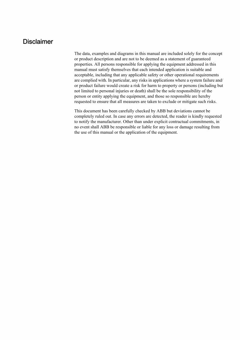
files include the description of the logical nodes, their data type templates and theused or supported services. The structure of the IED section follows the definitionsmade in the IEC 61850 standard.
Two basic IED types are used in system configuration.
• Station level IEDsare located on the station level and are identified as client IEDs when they reador write information from or to the bay IEDs. This functionality is representedby logical nodes of group “Information (I)”. These are the logical nodes (LN)= ITCI, IHMI and ITMI. Client IEDs are the receiver of information inmonitoring direction and sender of commands (control). These logical nodeshave no data objects. They are only used to link the report control blocks(BRCBs) from the server IEDs. They have to read their information about thesignals and the signal configuration from the bay IEDs. This is possible bychecking all control blocks for a link to it as a client.
• Bay level IEDsare located on the bay level and are identified as server IEDs when they reador write information vertically. When GOOSE messages are received, the baylevel IED also has the client role.
Section 3 1MRK 511 242-UEN -Substation Configuration description Language (SCL)
26 650 seriesCommunication Protocol Manual

en06000104.vsd
AP
Subnetwork
Control
IED
CVMMXU1
SB1.LD1
Server
LPHD
SXCBR1
SCSWI1
SXSWI1
SCSWI2
SXSWI2
SCSWI3
SXSWI3
SCSWI4
SXSWI4
SCSWI5
LLN0
Mod
CBOpCap
Origin
Data
DataAttribute
Beh
Health
NamePlt
ctlValPos
Loc
OpCnt
BlkOpn
BlkCls
stVal
q
t
LogicalNode
ctlModel
IEC06000104 V1 EN
Figure 4: Organization of LDs, LNs, DOs and DAs in an IED
• A server represents the communication interface to the subnetwork (Ethernet).• One or more logical device(s) (LD) are connected to a server.• A set of logical nodes belong to a LD.• The LN LLN0 is a special logical node per LD and contains for example the
data sets, the various control blocks, inputs (from GOOSE messages). In IED650 series, the data sets and the control blocks shall be located to LD0.
• The LN LPHD is a special logical node per LD and contains data objects thatdescribe the status of the physical device (the IED)
• Each logical node represents a function and contains a number of data objects(DO)
• Each DO includes a number of data attributes (DA)
The data objects represent information signals that may be routed to station levelIEDs or to other bay IEDs that are communicating with GOOSE. The signalengineering task is to select the requested signals (DOs) and link them to the clientIEDs as receiver. The control services are not directly engineered. They areincluded in the data objects, which handle both directions the command (control)
1MRK 511 242-UEN - Section 3Substation Configuration description Language (SCL)
650 series 27Communication Protocol Manual

and the response (monitoring). When routing the DO in monitoring direction, thecontrol is also known by the clients.
The number of data objects and data attributes per DO is defined by the used LNtype in this IED. The content of logical node types and DO types are defined in theDTT. This also means that the definitions in the DTT section have to be uniquewith an SCD file.
3.4 Tool concept
The IEC 61850-6 defines a number of roles for tools. In the Relion® series,PCM600 is defined as IED tool, and CCT600 is defined as system tool
The sections in SCL contain properties that are to be configured by these tools.There is no relation between one section and one specific tool. The task of the IEDtool is to configure all properties for the IED, while the system tool has the task todefine the place of the IED in the system and its communication dependencies. Forexample, the plant structure in PCM600 results in the subsystem section in SCLregarding the subsystem structure down to the IED level. The PCM600 alsoconfigures the IED section as a result of the IED configuration. In PCM600, theconfiguration properties for SCL are handled automatically as a result of theconfiguration, except for the receiving of GOOSE information that has adependency with the system tool.
IEC 61850 engineering with PCM600 and CCT600
PCM600:
• When an IED is instantiated, its place in the plant structure creates thecorresponding structure in the substation section in SCL. The communicationfacilities is also created in the communication section.
• The functionality of the IED is configured by using ACT in PCM600. For eachfunction, the corresponding logical device and logical node(s) is created in theIED section together with its type definition in data type template section
• The above forms the IED capabilities from a communication perspective andwill then be included in the file exported from PCM600 as SCD, ICD or CID file
(For top down engineering approach, the steps are included in the CID file of a pre-configured IED)
CCT600:
Section 3 1MRK 511 242-UEN -Substation Configuration description Language (SCL)
28 650 seriesCommunication Protocol Manual

• Open a SCD file or import/merge a SCD, ICD or CID file for the particularIED(s).
• For each IED, the user defines the datasets, the control blocks for reporting(this means unbufffered/buffered reporting and GOOSE) and the properties foreach report control block.
• If client definitions (like client. ICD) are required in the system configuration,they are merged into CCT600 and connected to the unbuffered/buffered reportcontrol blocks.
• For each IED, the primary/conducting equipment with their relation to theused logical nodes must be defined in the substation section.
• Logical nodes, which are not related to the conducting equipment, must beincluded in the bay level in the substation section.
• The resulting SCD file is exported from CCT600.
PCM600:
Import the SCD file to PCM600 to receive GOOSE data. For each IED that shallreceive GOOSE information, the received data is connected to the applicationsusing SMT in PCM600.
3.5 Engineering concept in IEC 61850-6
• Top-down approach means that the system engineering tool has ICD filesavailable for each IED to be included in the system configuration. The ICDfiles may be of an template type and represent a pre-configured IED.
• Bottom-up approach means that the configurations are produced by the IEDtool, and that are exported as ICD files (or SCD file) to be imported by systemtools.
1MRK 511 242-UEN - Section 3Substation Configuration description Language (SCL)
650 series 29Communication Protocol Manual

….IED A IED B IED Z
Client A Client B
IEDtool
Systemtool
IEC09000151-1-en.vsdIEC09000151 V1 EN
Figure 5: Relation between system and IED tools
Regardless of engineering approach, the idea is that the IED tool provides the CIDor ICD file for each IED. These ICD/CID files are then imported into the systemtool and merged into a SCD file, representing the complete substation or a part ofthe substation, like one for each voltage level.
Section 3 1MRK 511 242-UEN -Substation Configuration description Language (SCL)
30 650 seriesCommunication Protocol Manual

Section 4 Communication profile
The IEC 61850 standard is conceptually written to be independent of an existingcommunication media and message transmission concept. Out of this, a specificcommunication profile is decided and is been commonly used. The actual decisionis for
• Ethernet as the media• TCP/IP• ISO session and presentation layer• MMS (Manufacturing Message Specification (ISO 9506-1 and ISO 9506-2)
The IEC 61850 standard describes its requested services in ACSI, which iscontained in part 7-2 of the standard. The mapping to the MMS for all aspects ofservices and Ethernet usage is specified in part 8-1 of IEC 61850.
Each device manufacturer, which is a partner of an IEC 61850 basedcommunication network, has to take these two specifications and adapt theirrespective product to the requirements and definitions given in the standard. Tomake this profile visible to all other partners, so they can check what they canexpect and what they have to support, the PICS document is defined. The PICScontains in a table based form the possibility of a product or product family.
IED (server)(61850 services; part 7-2)
Communication(MMS services; part 8-1)
- Access Point (AP) / Address- GSE
IEC08000179.vsd
AP
IED (client)(61850 services; part 7-2)
Subnetwork
IED (server)(61850 services part; 7-2)
Communication(MMS services; part 8-1)
Communication(MMS services; part 8-1)
- Access Point (AP) / Address- GSE
- Access Point (AP) / Address- GSE
IEC08000179 V1 EN
Figure 6: IEC 61850 Protocol: related standards for communication
1MRK 511 242-UEN - Section 4Communication profile
650 series 31Communication Protocol Manual

SV GOOSE TimeSync(SNTP) MMS Protocol Suite GSSE
TCP/IPT-Profile
ISO COT-Profile
ISO/IEC 8802-2 LLC
GSSET-ProfileUDP/IP
ISO/IEC 8802-3 Ethertype
SampledValues(Multicast)
GenericObjectOrientedSubstationEvent
TimeSync
CoreACSIServices
GenericSubstationStatusEvent
ISO/IEC 8802-3
IEC09000153-1-en.vsd
IEC09000153 V1 EN
Figure 7: Overview of functionality and profiles according to IEC 61850-8-1
Out of this content, the implementation in the 650 series supports:
• GOOSE• TimeSync using SNTP• The peer-to-peer/vertical communication using MMS protocol suite with the T-
profile TCP/IP
For each of the above, the resulting underlying protocols as stated in figure 7.
See the PICS and PIXIT for more information.
Section 4 1MRK 511 242-UEN -Communication profile
32 650 seriesCommunication Protocol Manual

Section 5 Supported services
IEC 61850-7-2 describes the services in the standard. IEC 61850-8-1 describeshow the services are applied in the communication. The conformance documentscontain the main description about the supported services in the IED.
Services that are not mentioned in this chapter or in the conformance document arenot supported.
Data setDefine data sets by the SCD description.
Create data sets under LD0/LLN0.
SubstitutionSubstitution is supported for the respective DATA, according to IEC 61850-7-4,that have the substitution attributes defined.
Note that SubID and SubQ are not used.
Setting group control blockChange of setting group is supported, that is the actSG attribute. This attribute isnot one of the explicit definitions in SCL, but a consequence of the defined settinggroup control block according to IEC 61850-6.
There is only one setting group control block, which is located in LD0/LLN0(Logical Device/Logical Node 0).
Change or edit of setting values as well as reading of setting values is neithersupported nor visible in IEC 61850.
Note that the actual number of used setting groups is defined by theparameter MaxNoSetGRP in the function SETGRPS, which isconfigured in PST in PCM600.
Report control blockFor properties about report control blocks, see PIXIT.
UnBuffered reporting as well as Buffered reporting is supported.
1MRK 511 242-UEN - Section 5Supported services
650 series 33Communication Protocol Manual

Note that the parameters BufTm and IntPrd shall have the relationBufTm < IntPrd. For best efficiency, the BufTm should have IntPrdas common denominator, like n*BufTm = IntPrd, n is an arbitrarynumber.
Generic substation event (GOOSE)The structured GOOSE is supported. This means that the data sets can be definedwith FCDA as well as explicit attributes.
When explicit attributes are defined in the data sets, the number of such items in adata set is limited to 150.
The supported data types to be published and received over GOOSE are binaryvalues, double point values and measured values, together with their quality. Onreception of GOOSE message there is one signal for validity available for theapplications. The signal for validity represents all data in the received GOOSEtelegram. Invalid means that the correct message is not received within the1.8*maxTime parameter for the GOOSE Control Block (as defined in IEC61850-6). An incorrect message includes T=true, NeedsCom, wrong order ofattributes or any discrepancy in the GOOSE message layout.
Note that the data sets that are used or referred to by GOOSEcontrol blocks can only include a data attribute once. In otherwords, there may not be the same data attribute in more than onedata set.
When publishing a measured value, the user must take care which measured valuedata attributes are added to a data set. If the measured value is event-handled (likein the case of MMXU functions), then one can add that value directly to the dataset. If the value is not event-handled, (like in the case of Synchrocheck function), itis recommended to connect the value desired to be published to a MVGGIOfunction block (in ACT) and then use the measured value given by the MVGGIO.
Example of functions that have event-handled measured values (can be addeddirectly to the data set).
• CVMMXN - Measurements• CMMXU - Phase current measurement• VMMXU - Phase-phase voltage measurement• CMSQI - Current sequence component measurement• VMSQI - Voltage sequence measurement• VNMMXU - Phase-neutral voltage measurement• MVGGIO - IEC61850 generic communication I/ O functions
Example of functions that have event-handled measured values, but they cannot beadded directly to the data set (need to be connected to a MVGGIO function block).
Section 5 1MRK 511 242-UEN -Supported services
34 650 seriesCommunication Protocol Manual

• PCGGIO - Pulse Counter• ETPMMTR - Function for energy calculation and demand handling• LMBRFLO - Fault Locator• SESRSYN - Synchrocheck, energizing check, and synchronizing• SSCBR - Circuit breaker condition monitoring• SSIMG - Insulation liquid monitoring function• SSIML - Circuit breaker condition monitoring• VR2PVOC - Voltage-restrained time overcurrent protection• DNSPTOC - Negative sequence based overcurrent function
ControlOf the different control sequences, the ‘direct-with-normal-security’ and ‘SBO-with-enhanced’ security are supported (defined by the ctlModel parameter, IEC61850-7-2).
The command model can be changed for some functions by using PCM600 or PST.From communication perspective, in IEC61850 this parameter is read-only.
Check bits; interlock check and synchrocheck check, are only valid for LN typesbased upon CSWI class.
Verification of Originator Category is supported, see also PIXIT.
Time and time synchronizationFor properties about time synchronization, see PIXIT and Time synchronizationdescription in the technical manual and the application manual.
File transferSee PIXIT.
1MRK 511 242-UEN - Section 5Supported services
650 series 35Communication Protocol Manual

36

Section 6 Data sets and control blocks
6.1 Data sets
IEC 61850 has defined data sets and report control blocks for signal transmissionin monitoring direction. Data sets are also used for GOOSE messages in horizontaldirection. The project defines the data objects or single data attributes that shouldbe collected in a data set. The following figure shows a data set where all positioninformation of the apparatuses of a bay are put into one data set.
The vendor of an IED can define data sets as defaults that are part of the IED andalways available. They need to be linked to the client IEDs only when to use themas they are. The vendor has to declare when these data sets can be modified toprojects need or not.
en06000106.vsd
LD1/SXCBR1.Pos FC=ST
LD1/SXSWI1.Pos FC=ST
LD1/SXSWI2.Pos FC=ST
LD1/SXSWI3.Pos FC=ST
LD1/SXSWI4.Pos FC=ST
LD1/LLN0.AppPosDATA-SET
CVMMXU1
LD1
LPHD
SXCBR1
SCSWI1
SXSWI1
SCSWI2
SXSWI2
SCSWI3
SXSWI3
SCSWI4
SXSWI4
SCSWI5
LLN0
Origin
stVal
q
t
Pos
Pos
Pos
Pos
Pos
IEC06000106 V1 EN
Figure 8: IEC 61850–7–2: Example of a data set
General rules for data set configuration:
1MRK 511 242-UEN - Section 6Data sets and control blocks
650 series 37Communication Protocol Manual

• All data objects or their data attributes which are signals in monitoringdirection can be selected for a data set.
• Only those data attributes of a data object can/will be selected which have thesame function constraint (FC).
• Data objects with different FC can be selected for a data set. For example,DOs with FC = ST and DOs with FC=MX can be member in one data set.
• A single data attribute can be selected when it is specified with a triggeroption. For example, the data attribute stVal of the data object Pos can beselected as a member of a data set, because it is specified with the triggeroption data change detected (dchg).
The description of the data sets with name and the list of data object members(FCDAs is included in the SCL file in the IED section in the Logical devicesubsection. As specified in IEC 61850–7–2 clause 9, the data sets are part of alogical node. They are most likely included in the LLN0.
6.2 Report control block (URCB/BRCB)
To be able to transmit the signals configured in a DataSet, a report control blockmust be configured to handle and specify how the events are transmitted to theclients. There are two types of report control blocks, unbuffered and buffered. Thebuffered report control block stores the events during a communication interrupt,while the unbuffered is sent upon data change and not stored during interruption.
The content of a BRCB is listed in IEC 61850-7-2 in clause 14. The BRCBcontains many attributes which are of interest to handle and secure thecommunication between the client and the server and may be set once as default ina project. Others are of application interest in the way events are handled in a project.
• Buffer time (valid only for BRCB)• This parameter describes how long the report should wait for other
expected events before it sends the report to the client. When it is known,that additional events are generated as a follow up, it is useful to wait,for example, 500 ms for additional events stored in the report. Thisfeature reduces the number of telegrams transmitted in case of a burst ofchanges. But on the other side it increases the overall transaction time forevents from IED input to presentation on HSI, which is normally definedto be one second.
• Trigger options• The data attributes know three different trigger options (dchg, qchg,
dupd). Within the BRCB, the two other can be defined (integrity andgeneral interrogation). The attribute Trigger option is a multiple choiceand allows to mask the supported trigger options in this BRCB.
• Integrity period• When integrity is selected in the trigger option attribute, it is needed to
define an integrity period to force the transmission of all data listed in
Section 6 1MRK 511 242-UEN -Data sets and control blocks
38 650 seriesCommunication Protocol Manual

the DataSet. This is done by the attribute Integrity period. This featurecan be used as a background cycle to ensure that the process image in allpartners is the same. Nobody is perfect and someone in the long chainfrom the contact up to the NCC may have lost an event. The backgroundcycle can repair it.
• General interrogation• A general interrogation is only done on request from a client. Not all Data-
sets may contain information which is needed for a general update of theclient. For example data with T(ransient) = TRUE are not part of a GI.When the BRCB attribute general interrogation is set to TRUE a GIrequest from the client will be handled. The report handler will transmitall data defined in the Data-set with their actual values. The IEC 61850standard defines that all buffered events shall be transmitted first beforethe GI is started. A running GI shall be stopped and a new GI shall bestarted, when a new GI request is received while a GI is running.
• Purge buffer (valid only for BRCB)• This BRCB attribute can be used by a client to clean the event buffer
from old events. The events are discarded on request of the client. Thisfeature can be used to delete old events not transmitted to the client dueto stopped communication. After the link is reestablished the client candecide to clean the buffer or to receive the history.
Trigger OptionsIEC 61850 has defined in total five different TrgOp. Three of them belonging todata attributes and marked per data attribute in the column TrgOp of the CDCtables in part 7–3. The other two belonging to the configuration of control blocks.
• dchg = data-change• The classical trigger. Whenever a process value has changed its value
either binary or a measurement a transmission is done. The standard doesnot define how to detect and inform the logical node.
• qchg = quality change• Looking to the possibilities of the quality data attribute type (q) any
changes in the quality description will be transmitted.• dupd = data value update
• This trigger option give the possibility to define that a transmissionshould be done on a condition which can be controlled by the application.
• integrity• This trigger forces the transmission of all process values defined in the
data set when a timer value (the integrity period) expires. It can be usedfor example to update a process signal in the background (for example,every 15 minutes).
• general interrogation
1MRK 511 242-UEN - Section 6Data sets and control blocks
650 series 39Communication Protocol Manual

• This trigger is forced by the clients (= station level IED; NCC gateway,station HMI, ...). Normally a GI is asked for, when the client and theserver start or restart a session. When the client is able to receive theactual values and when the logical device has scanned all process valuesat least once, an image of the actual process signal status can betransmitted to the client.
Note that the possible trigger options for each attributeare included and defined in the datatype template sectionin SCL.
Link BRCB to a client LNThe BRCB has to know to whom the events shall be transmitted. This is the signalrouting engineering step. The IEC standard 61850–6 describes that this is given byincluding the LN of the client IED in the ReportBlockEnabled option.
The selected client IED with the corresponding LN, for example, ITCI is includedin the SCL structure of the Report Control description of the IED section.
The description of the BRCB with selected DataSet, configured parameters andselected IEDs is included in the SCL file in the IED section in the LN0 structurefor the LD where this LN0 belongs to.
en06000107.vsd
LD1/SXCBR1.Pos FC=ST
LD1/SXSWI1.Pos FC=ST
LD1/SXSWI2.Pos FC=ST
LD1/SXSWI3.Pos FC=ST
LD1/SXSWI4.Pos FC=ST
LD1/LLN0.AppPosDATA-SET
IEDHSI
Client 1
IEDNCC GW 1
Client 2
IEDNCC GW m
Client m
IED 1
Server 1
Subnetwork
ITCI2ITCI1IHSI1
LLN0
IEC06000107 V1 EN
Figure 9: Link BRCB to a client LN
Section 6 1MRK 511 242-UEN -Data sets and control blocks
40 650 seriesCommunication Protocol Manual

6.3 GOOSE Control Blocks (GoCB)
en06000109.vsd
Sen
d
Data-set
Rec
eive
Rec
eive
LN
LN
LNLN
LN
Sen
d
Data-set
Rec
eive
Rec
eive
LNLN
LN LN
Sen
d
Data-set
Rec
eive
Rec
eive
LN
LNLN
LNLN
LN
Subnetwork
LN0
GoCB
DataSet
InputGoCBGoCB
DataSetDataSet
InputInput
Comm.GSE
LD1
Server
LN0
GoCB
DataSet
InputGoCBGoCB
DataSetDataSet
InputInput
Comm.GSE
LD1
Server
IEC06000109 V1 EN
Figure 10: IEC 61850: Principle operation of GOOSE messages
The Generic Object Oriented Substation Event (GOOSE) class model is used todistribute input and output data values between IEDs on bay level (in horizontaldirection) through the use of multicast services. GOOSE messages bypass theserver and enable fast transmission from a publisher to one or several subscribers(receivers).
GOOSE messages are unidirectional, send only messages which request anapplication specific method to secure that the sender and the receiver of themessage operate safely. This implies that the receiver of the GOOSE messagedistributes also GOOSE messages and closes the loop for communication (request
1MRK 511 242-UEN - Section 6Data sets and control blocks
650 series 41Communication Protocol Manual

— respond on application level). The return message is not a must. It depends onthe application in which way a confirmation may be done.
The GOOSE service model of IEC 61850-7-2 provides the possibility for fast andreliable system-wide distribution of input and output data values. Thisimplementation uses a specific scheme of re-transmission to achieve theappropriate level of reliability. When a GOOSE server generates aSendGOOSEMessage request, the current data set values are encoded in a GOOSEmessage and transmitted on the multicast association. The event that causes theserver to invoke a SendGOOSE service is a local application issue as defined inIEC 61850-7-2. Each update may generate a message in order to minimizethroughput time.
Additional reliability is achieved by re-transmitting the same data (with graduallyincreasing SqNum and retransmission time).
T0 retransmission in stable conditions (no event for a long time)
(T0) retransmission in stable conditions may be shortened by an event
T1 shortest retransmission time after the event
T2, T3 retransmission times until achieving the stable conditions time
Time of transmission
T0 (T0) T1 T1 T2 T3 T0
eventIEC09000152-1-en.vsd
IEC09000152 V1 EN
Figure 11: Transmission time for events
Each message in the retransmission sequence carries a timeAllowedToLiveparameter that informs the receiver of the maximum time to wait for the next re-transmission. If a new message is not received within that time interval, thereceiver assumes that the association is lost. The specific intervals used by anyGOOSE publisher are a local issue. The timeAllowedtoLive parameter informssubscribers of how long to wait. In 650 series, the detection time is1.8*timeAllowedToLive to cope with possible transmission delays.
Section 6 1MRK 511 242-UEN -Data sets and control blocks
42 650 seriesCommunication Protocol Manual

The GOOSE message concept is used for all application functions where two ormore IEDs are involved. Typical example is the station-wide interlockingprocedure or breaker failure protection.
Figure 10 shows the GOOSE concept for three IEDs which interchange GOOSEmessages between each other.
To send GOOSE messages a GoCB must be defined and a data set is needed thatcontains the data objects of single data attributes to be sent.
A GOOSE message is forced to be transmitted when a trigger change is detectedfor a data attribute. All members of the data set are copied in the send buffer withtheir actual value and the message is sent. The subscribers, who knows the addressof this GOOSE message, receives the telegram. The GOOSE message includes forexample sequence number to verify that all messages are received.
The concept that has to be done in case of for example a lost message is part of theapplication and not described in the standard.
A GoCB has to be defined per GOOSE-DataSet.
GOOSE messages bypass the server and send direct from the communication parton the Ethernet. This is identified for the communication in the SCLcommunication section in the GSE element, where the name of the GoCB is listedunder the ConnectedAP.
Link GoCB to an IEDThe IEDs that should receive the GOOSE message must be known and they haveto be informed in the engineering state that they receive GOOSE messages andwhich one. This is given when the external Reference, the name of the IED and themember of the data set is included in the LN0 under the structure of the LD of thereceiving IED. This part is identified as “Inputs”.
1MRK 511 242-UEN - Section 6Data sets and control blocks
650 series 43Communication Protocol Manual

44

Section 7 Logical node data model
The data model used by IEC 61850 is based on logical nodes containing a set ofdata objects. The data model is defined in the standards.
• IEC 61850-7-4 Compatible logical node classes and data classes• IEC 61850-7-3 Common data classes
The standard describes only classes of logical nodes and data objects on one sideand common data classes for the data object attributes. Also here it is given has theelements in these classes are defined as:
• Mandatory (M)• Optional (O)• Conditional optional (Cxxx)• In addition, the IEC 61850 states rules for adding vendor-specific definitions
to the standard, in order to cope with extra functionality.
The possible description of the data model according to the standard allows toadapt a logical node of a LN class to that what the product is supporting or usingfor this LN. This definition of what parts of a class is used in the actual product andpossible addition is called a type, according to IEC 61850-6. There are LN typesbased upon LN classes. The LN type attributes are called Data Objects (or DATA)and are in of DO types, base upon respective CDC class. This allows all partners inthe IEC 61850 project who need this LN to understand the LN in all details for thecommunication part.
The IEC 61850 standard does not describe the functionality and way of operation.Each supplier has to describe this separately. ABB has described their functionblocks that represent a logical node and all other function blocks in the technicalmanuals. This chapter in the communication protocol manual has two tasks:
• Describe the Logical Node types and their data object attribute types.• Make the link to the description of the function block.
7.1 Common data objects in each logical node
The IEC 61850 standard describes in part 7-5, a Common Logical Node. The dataobjects contained in that LN are both mandatory and optional. The mandatory dataobjects have to be included in each LN. This clause describes the general handlingof the data objects within the 650 series products.
1MRK 511 242-UEN - Section 7Logical node data model
650 series 45Communication Protocol Manual

The mandatory data objects as defined in IEC 61850-7-4 as part of the CommonLogical Node are Mode, Behavior, Health and NamePlate.
Mode
The operation modes ON (enabled) and BLOCKED are supported remotely by acommand or locally from the LHMI of the IED. The TEST and the TEST/BLOCKED mode can be operated locally from the LHMI or by using PCM600.
The state OFF can be set from the LHMI or by using PCM600 for the functionshaving the setting 'operation'.
Note also that for functions in other Logical devices than LD0, the Mod can onlybe controlled by communication on LLN0.
Behaviour
The operational mode as given by the Mode control is shown in the data object Behwith the priority rules as described for Beh in clause 6 of IEC 61850-7-4.
The Beh shows the actual state of the function, dependent upon the hierarchydescribed in IEC 61850-7-4, clause 6.
Health
The 650 series products show always only the state "green" = Ok.
NamePlt
The name of the logical node and its relation to namespace definition are shown inthe data object NamePlt as specified for the SCL structure.
7.2 Logical nodes for automatic control
7.2.1 Automatic tap changer control ATCC
7.2.1.1 Automatic voltage control for tapchanger, parallel control TR8ATCC
LN type LN prefix LN class Function block name
TR8ATCC (revision 3) TR8 ATCC TR8ATCC
Section 7 1MRK 511 242-UEN -Logical node data model
46 650 seriesCommunication Protocol Manual

Table 6: TR8ATCC Logical node data (instance 1)
DO name DO type DA name FC T Signal Mon/Cmd
Description
Mod a_dINC Oper.ctlVal CO - - Cmd Mode parameter for 61850
Oper.origin.orCat CO - - Cmd Mode parameter for 61850
Oper.origin.orIdent CO - - Cmd Mode parameter for 61850
Oper.ctlNum CO - - Cmd Mode parameter for 61850
Oper.T CO - - Cmd Mode parameter for 61850
Oper.Test CO - - Cmd Mode parameter for 61850
Oper.Check CO - - Cmd Mode parameter for 61850
stVal ST - - Mon Mode status value parameter for61850
q ST - - Mon Mode status value parameter for61850
t ST - - Mon Mode status value parameter for61850
Beh a_dINS stVal ST - Beh Mon Behaviour parameter for 61850
q ST - Beh Mon Behaviour parameter for 61850
t ST - Beh Mon Behaviour parameter for 61850
LTCBlk a_dSPC Oper.ctlVal CO - - Cmd Command parameter forIEC61850
Oper.origin.orCat CO - - Cmd Command parameter forIEC61850
Oper.origin.orIdent CO - - Cmd Command parameter forIEC61850
Oper.ctlNum CO - - Cmd Command parameter forIEC61850
Oper.T CO - - Cmd Command parameter forIEC61850
Oper.Test CO - - Cmd Command parameter forIEC61850
Oper.Check CO - - Cmd Command parameter forIEC61850
stVal ST - - Mon Used by CH
q ST - - Mon Used by CH
t ST - - Mon Used by CH
Loc a_dSPS stVal ST - - Mon Local commands selected
q ST - - Mon Local commands selected
t ST - - Mon Local commands selected
BlkV a_dSPS stVal ST - UBLK Mon Busbar voltage below the set limitvoltBusbBlockLimit
q ST - UBLK Mon Busbar voltage below the set limitvoltBusbBlockLimit
t ST - UBLK Mon Busbar voltage below the set limitvoltBusbBlockLimit
HiTapPos b_dINS stVal ST - - Mon Tap position for maximum voltage
Table continues on next page
1MRK 511 242-UEN - Section 7Logical node data model
650 series 47Communication Protocol Manual

DO name DO type DA name FC T Signal Mon/Cmd
Description
HiTapPos b_dINS q ST - - Mon Tap position for maximum voltage
t ST - - Mon Tap position for maximum voltage
LoTapPos b_dINS stVal ST - - Mon Tap position for minimum voltage
q ST - - Mon Tap position for minimum voltage
t ST - - Mon Tap position for minimum voltage
CircA b_dMV mag.f MX - ICIRCUL Mon Circulating current
q MX - ICIRCUL Mon Circulating current
t MX - ICIRCUL Mon Circulating current
LodA b_dMV mag.f MX - - Mon Magnitude of measured loadcurrent (service value)
q MX - - Mon Magnitude of measured loadcurrent (service value)
t MX - - Mon Magnitude of measured loadcurrent (service value)
CtlV b_dMV mag.f MX - BUSVOLT Mon Average of measured busbarvoltage (service value)
q MX - BUSVOLT Mon Average of measured busbarvoltage (service value)
t MX - BUSVOLT Mon Average of measured busbarvoltage (service value)
TapChg c_dBSC Oper.ctlVal CO - - Cmd Command parameter forIEC61850
Oper.origin.orCat CO - - Cmd Command parameter forIEC61850
valWTr.posVal ST - - Mon Tap position
Oper.origin.orIdent CO - - Cmd Command parameter forIEC61850
valWTr.transInd ST - - Mon Tap position change in progress
Oper.ctlNum CO - - Cmd Command parameter forIEC61850
Oper.T CO - - Cmd Command parameter forIEC61850
Oper.Test CO - - Cmd Command parameter forIEC61850
Oper.Check CO - - Cmd Command parameter forIEC61850
q ST - - Mon Tap position
t ST - - Mon Tap position
TotW c_dMV mag.f MX - P Mon Calculated active power (servicevalue)
q MX - P Mon Calculated active power (servicevalue)
t MX - P Mon Calculated active power (servicevalue)
Table continues on next page
Section 7 1MRK 511 242-UEN -Logical node data model
48 650 seriesCommunication Protocol Manual

DO name DO type DA name FC T Signal Mon/Cmd
Description
TotVAr c_dMV mag.f MX - Q Mon Calculated reactive power(service value)
q MX - Q Mon Calculated reactive power(service value)
t MX - Q Mon Calculated reactive power(service value)
ParOp c_dSPC stVal ST - PARALLEL Mon Transformer operates in parallelmode
q ST - PARALLEL Mon Transformer operates in parallelmode
t ST - PARALLEL Mon Transformer operates in parallelmode
LTCId v1_dINS stVal ST - - Mon Identity of the transformer
q ST - - Mon Identity of the transformer
t ST - - Mon Identity of the transformer
ParSet v1_dINS stVal ST - - Mon Setting value for transformer inparallel mode
q ST - - Mon Setting value for transformer inparallel mode
t ST - - Mon Setting value for transformer inparallel mode
AutoCtl v1_dSPC Oper.ctlVal CO - - Cmd Command parameter forIEC61850
Oper.origin.orCat CO - - Cmd Command parameter forIEC61850
Oper.origin.orIdent CO - - Cmd Command parameter forIEC61850
Oper.ctlNum CO - - Cmd Command parameter forIEC61850
Oper.T CO - - Cmd Command parameter forIEC61850
Oper.Test CO - - Cmd Command parameter forIEC61850
Oper.Check CO - - Cmd Command parameter forIEC61850
stVal ST - AUTO Mon Automatic control mode is active
q ST - AUTO Mon Automatic control mode is active
t ST - AUTO Mon Automatic control mode is active
LVA1On v1_dSPC Oper.ctlVal CO - - Cmd Command parameter forIEC61850
Oper.origin.orCat CO - - Cmd Command parameter forIEC61850
Oper.origin.orIdent CO - - Cmd Command parameter forIEC61850
Oper.ctlNum CO - - Cmd Command parameter forIEC61850
Table continues on next page
1MRK 511 242-UEN - Section 7Logical node data model
650 series 49Communication Protocol Manual

DO name DO type DA name FC T Signal Mon/Cmd
Description
LVA1On v1_dSPC Oper.T CO - - Cmd Command parameter forIEC61850
Oper.Test CO - - Cmd Command parameter forIEC61850
Oper.Check CO - - Cmd Command parameter forIEC61850
stVal ST - - Mon Setting LVAConst1 is used(service value)
q ST - - Mon Setting LVAConst1 is used(service value)
t ST - - Mon Setting LVAConst1 is used(service value)
LVA2On v1_dSPC Oper.ctlVal CO - - Cmd Command parameter forIEC61850
Oper.origin.orCat CO - - Cmd Command parameter forIEC61850
Oper.origin.orIdent CO - - Cmd Command parameter forIEC61850
Oper.ctlNum CO - - Cmd Command parameter forIEC61850
Oper.T CO - - Cmd Command parameter forIEC61850
Oper.Test CO - - Cmd Command parameter forIEC61850
Oper.Check CO - - Cmd Command parameter forIEC61850
stVal ST - - Mon Setting LVAConst2 is used(service value)
q ST - - Mon Setting LVAConst2 is used(service value)
t ST - - Mon Setting LVAConst2 is used(service value)
LVA3On v1_dSPC Oper.ctlVal CO - - Cmd Command parameter forIEC61850
Oper.origin.orCat CO - - Cmd Command parameter forIEC61850
Oper.origin.orIdent CO - - Cmd Command parameter forIEC61850
Oper.ctlNum CO - - Cmd Command parameter forIEC61850
Oper.T CO - - Cmd Command parameter forIEC61850
Oper.Test CO - - Cmd Command parameter forIEC61850
Oper.Check CO - - Cmd Command parameter forIEC61850
stVal ST - - Mon Setting LVAConst3 is used(service value)
Table continues on next page
Section 7 1MRK 511 242-UEN -Logical node data model
50 650 seriesCommunication Protocol Manual
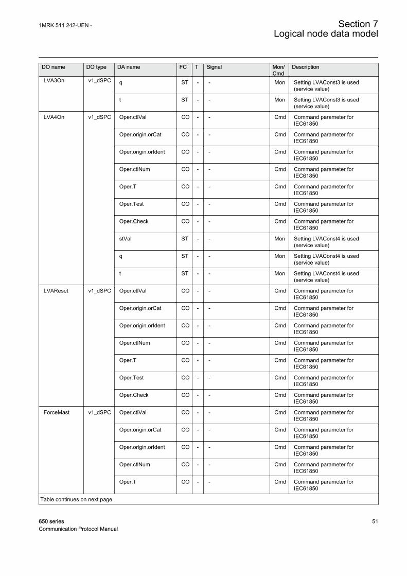
DO name DO type DA name FC T Signal Mon/Cmd
Description
LVA3On v1_dSPC q ST - - Mon Setting LVAConst3 is used(service value)
t ST - - Mon Setting LVAConst3 is used(service value)
LVA4On v1_dSPC Oper.ctlVal CO - - Cmd Command parameter forIEC61850
Oper.origin.orCat CO - - Cmd Command parameter forIEC61850
Oper.origin.orIdent CO - - Cmd Command parameter forIEC61850
Oper.ctlNum CO - - Cmd Command parameter forIEC61850
Oper.T CO - - Cmd Command parameter forIEC61850
Oper.Test CO - - Cmd Command parameter forIEC61850
Oper.Check CO - - Cmd Command parameter forIEC61850
stVal ST - - Mon Setting LVAConst4 is used(service value)
q ST - - Mon Setting LVAConst4 is used(service value)
t ST - - Mon Setting LVAConst4 is used(service value)
LVAReset v1_dSPC Oper.ctlVal CO - - Cmd Command parameter forIEC61850
Oper.origin.orCat CO - - Cmd Command parameter forIEC61850
Oper.origin.orIdent CO - - Cmd Command parameter forIEC61850
Oper.ctlNum CO - - Cmd Command parameter forIEC61850
Oper.T CO - - Cmd Command parameter forIEC61850
Oper.Test CO - - Cmd Command parameter forIEC61850
Oper.Check CO - - Cmd Command parameter forIEC61850
ForceMast v1_dSPC Oper.ctlVal CO - - Cmd Command parameter forIEC61850
Oper.origin.orCat CO - - Cmd Command parameter forIEC61850
Oper.origin.orIdent CO - - Cmd Command parameter forIEC61850
Oper.ctlNum CO - - Cmd Command parameter forIEC61850
Oper.T CO - - Cmd Command parameter forIEC61850
Table continues on next page
1MRK 511 242-UEN - Section 7Logical node data model
650 series 51Communication Protocol Manual

DO name DO type DA name FC T Signal Mon/Cmd
Description
ForceMast v1_dSPC Oper.Test CO - - Cmd Command parameter forIEC61850
Oper.Check CO - - Cmd Command parameter forIEC61850
stVal ST - - Mon Transformer is forced to be amaster
q ST - - Mon Transformer is forced to be amaster
t ST - - Mon Transformer is forced to be amaster
HiV v1_dSPS stVal ST - UHIGH Mon Busbar voltage above the set limitvoltBusbMaxLimit
q ST - UHIGH Mon Busbar voltage above the set limitvoltBusbMaxLimit
t ST - UHIGH Mon Busbar voltage above the set limitvoltBusbMaxLimit
LoV v1_dSPS stVal ST - ULOW Mon Busbar voltage below the set limitvoltBusbMinLimit
q ST - ULOW Mon Busbar voltage below the set limitvoltBusbMinLimit
t ST - ULOW Mon Busbar voltage below the set limitvoltBusbMinLimit
AutoSlave v1_dSPS stVal ST - - Mon Auto slave activated
q ST - - Mon Auto slave activated
t ST - - Mon Auto slave activated
T1ParGr v1_dSPS stVal ST - T1PG Mon Transformer 1 included in parallelgroup
q ST - T1PG Mon Transformer 1 included in parallelgroup
t ST - T1PG Mon Transformer 1 included in parallelgroup
T2ParGr v1_dSPS stVal ST - T2PG Mon Transformer 2 included in parallelgroup
q ST - T2PG Mon Transformer 2 included in parallelgroup
t ST - T2PG Mon Transformer 2 included in parallelgroup
T3ParGr v1_dSPS stVal ST - T3PG Mon Transformer 3 included in parallelgroup
q ST - T3PG Mon Transformer 3 included in parallelgroup
t ST - T3PG Mon Transformer 3 included in parallelgroup
T4ParGr v1_dSPS stVal ST - T4PG Mon Transformer 4 included in parallelgroup
q ST - T4PG Mon Transformer 4 included in parallelgroup
Table continues on next page
Section 7 1MRK 511 242-UEN -Logical node data model
52 650 seriesCommunication Protocol Manual

DO name DO type DA name FC T Signal Mon/Cmd
Description
T4ParGr v1_dSPS t ST - T4PG Mon Transformer 4 included in parallelgroup
T1Master v1_dSPS stVal ST - - Mon Transformer 1 is master
q ST - - Mon Transformer 1 is master
t ST - - Mon Transformer 1 is master
T2Master v1_dSPS stVal ST - - Mon Transformer 2 is master
q ST - - Mon Transformer 2 is master
t ST - - Mon Transformer 2 is master
T3Master v1_dSPS stVal ST - - Mon Transformer 3 is master
q ST - - Mon Transformer 3 is master
t ST - - Mon Transformer 3 is master
T4Master v1_dSPS stVal ST - - Mon Transformer 4 is master
q ST - - Mon Transformer 4 is master
t ST - - Mon Transformer 4 is master
SimTap v1_dSPS stVal ST - - Mon Simultaneous tapping activated
q ST - - Mon Simultaneous tapping activated
t ST - - Mon Simultaneous tapping activated
CommFlt v1_dSPS stVal ST - COMMERR Mon Communication error
q ST - COMMERR Mon Communication error
t ST - COMMERR Mon Communication error
HiWFwd v1_dSPS stVal ST - PGTFWD Mon Active power above the set limitpowerActiveForw
q ST - PGTFWD Mon Active power above the set limitpowerActiveForw
t ST - PGTFWD Mon Active power above the set limitpowerActiveForw
HiWRv v1_dSPS stVal ST - PLTREV Mon Active power below the set limitpowerActiveRev
q ST - PLTREV Mon Active power below the set limitpowerActiveRev
t ST - PLTREV Mon Active power below the set limitpowerActiveRev
HiVArFwd v1_dSPS stVal ST - QGTFWD Mon Reactive power above the setlimit powerReactiveForw
q ST - QGTFWD Mon Reactive power above the setlimit powerReactiveForw
t ST - QGTFWD Mon Reactive power above the setlimit powerReactiveForw
HiVArRv v1_dSPS stVal ST - QLTREV Mon Reactive power below the setlimit powerReactiveRev
q ST - QLTREV Mon Reactive power below the setlimit powerReactiveRev
t ST - QLTREV Mon Reactive power below the setlimit powerReactiveRev
Table continues on next page
1MRK 511 242-UEN - Section 7Logical node data model
650 series 53Communication Protocol Manual

DO name DO type DA name FC T Signal Mon/Cmd
Description
CircABlk v1_dSPS stVal ST - ICIRC Mon Block from high circulating current
q ST - ICIRC Mon Block from high circulating current
t ST - ICIRC Mon Block from high circulating current
HiABlk v1_dSPS stVal ST - IBLK Mon One phase current is above theset limit
q ST - IBLK Mon One phase current is above theset limit
t ST - IBLK Mon One phase current is above theset limit
ExLowerBlk v1_dSPS stVal ST - - Mon External block of lower commandactivated
q ST - - Mon External block of lower commandactivated
t ST - - Mon External block of lower commandactivated
ExRaiseBlk v1_dSPS stVal ST - - Mon External block of raise commandactivated
q ST - - Mon External block of raise commandactivated
t ST - - Mon External block of raise commandactivated
Adapt v1_dSPS stVal ST - ADAPT Mon Transformer is adapting
q ST - ADAPT Mon Transformer is adapting
t ST - ADAPT Mon Transformer is adapting
DayHuntAlm v1_dSPS stVal ST - DAYHUNT Mon Number of commands within thelast 24 hours exceeded maximumlevel
q ST - DAYHUNT Mon Number of commands within thelast 24 hours exceeded maximumlevel
t ST - DAYHUNT Mon Number of commands within thelast 24 hours exceeded maximumlevel
HrHuntAlm v1_dSPS stVal ST - HOURHUNT Mon Number of commands within thelatest hour exceeded maximumlevel
q ST - HOURHUNT Mon Number of commands within thelatest hour exceeded maximumlevel
t ST - HOURHUNT Mon Number of commands within thelatest hour exceeded maximumlevel
HuntAlm v1_dSPS stVal ST - HUNTING Mon Number of commands in oppositedirection exceeded maximumlevel
q ST - HUNTING Mon Number of commands in oppositedirection exceeded maximumlevel
Table continues on next page
Section 7 1MRK 511 242-UEN -Logical node data model
54 650 seriesCommunication Protocol Manual

DO name DO type DA name FC T Signal Mon/Cmd
Description
HuntAlm v1_dSPS t ST - HUNTING Mon Number of commands in oppositedirection exceeded maximumlevel
VDif v1_dSPS stVal ST - VTALARM Mon VT supervision alarm
q ST - VTALARM Mon VT supervision alarm
t ST - VTALARM Mon VT supervision alarm
MSMode v1_dSPS stVal ST - - Mon Master slave is active
q ST - - Mon Master slave is active
t ST - - Mon Master slave is active
Disc v1_dSPS stVal ST - - Mon Transformer is disconnected
q ST - - Mon Transformer is disconnected
t ST - - Mon Transformer is disconnected
TotBlock v1_dSPS stVal ST - TOTBLK Mon Block of auto and manualcommands
q ST - TOTBLK Mon Block of auto and manualcommands
t ST - TOTBLK Mon Block of auto and manualcommands
AutoBlock v1_dSPS stVal ST - AUTOBLK Mon Block of auto commands
q ST - AUTOBLK Mon Block of auto commands
t ST - AUTOBLK Mon Block of auto commands
DiffPosMF v1_dSPS stVal ST - OUTOFPOS Mon Difference in tap positionsexceeded the set limit
q ST - OUTOFPOS Mon Difference in tap positionsexceeded the set limit
t ST - OUTOFPOS Mon Difference in tap positionsexceeded the set limit
MFFlt v1_dSPS stVal ST - MFERR Mon Number of masters is differentfrom one
q ST - MFERR Mon Number of masters is differentfrom one
t ST - MFERR Mon Number of masters is differentfrom one
LodAIm V10_dMV mag.f MX - ATCCOUT Mon Group connection to YLTCIN
q MX - ATCCOUT Mon Group connection to YLTCIN
t MX - ATCCOUT Mon Group connection to YLTCIN
LodARe V11_dMV mag.f MX - ATCCOUT Mon Group connection to YLTCIN
q MX - ATCCOUT Mon Group connection to YLTCIN
t MX - ATCCOUT Mon Group connection to YLTCIN
BusV V12_dMV mag.f MX - ATCCOUT Mon Group connection to YLTCIN
q MX - ATCCOUT Mon Group connection to YLTCIN
t MX - ATCCOUT Mon Group connection to YLTCIN
SetV V13_dMV mag.f MX - ATCCOUT Mon Group connection to YLTCIN
Table continues on next page
1MRK 511 242-UEN - Section 7Logical node data model
650 series 55Communication Protocol Manual
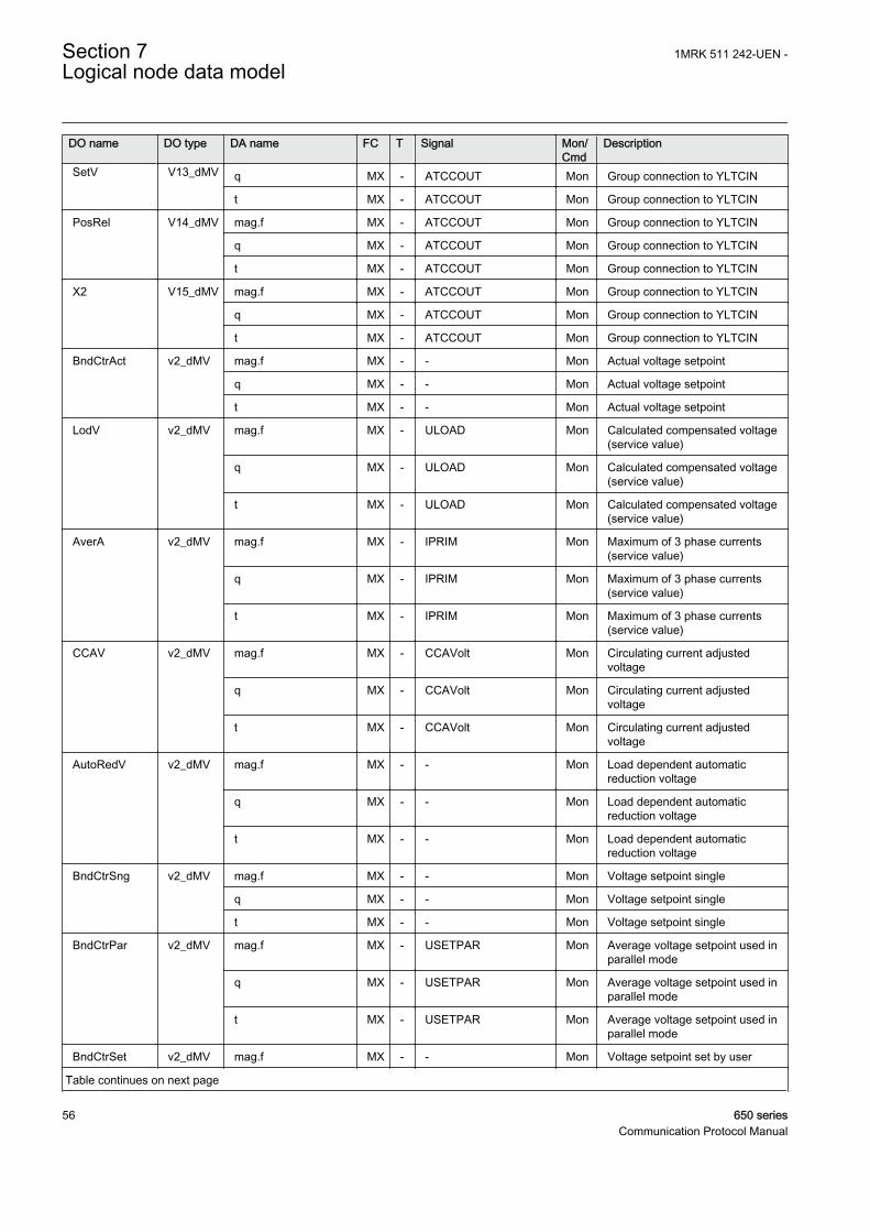
DO name DO type DA name FC T Signal Mon/Cmd
Description
SetV V13_dMV q MX - ATCCOUT Mon Group connection to YLTCIN
t MX - ATCCOUT Mon Group connection to YLTCIN
PosRel V14_dMV mag.f MX - ATCCOUT Mon Group connection to YLTCIN
q MX - ATCCOUT Mon Group connection to YLTCIN
t MX - ATCCOUT Mon Group connection to YLTCIN
X2 V15_dMV mag.f MX - ATCCOUT Mon Group connection to YLTCIN
q MX - ATCCOUT Mon Group connection to YLTCIN
t MX - ATCCOUT Mon Group connection to YLTCIN
BndCtrAct v2_dMV mag.f MX - - Mon Actual voltage setpoint
q MX - - Mon Actual voltage setpoint
t MX - - Mon Actual voltage setpoint
LodV v2_dMV mag.f MX - ULOAD Mon Calculated compensated voltage(service value)
q MX - ULOAD Mon Calculated compensated voltage(service value)
t MX - ULOAD Mon Calculated compensated voltage(service value)
AverA v2_dMV mag.f MX - IPRIM Mon Maximum of 3 phase currents(service value)
q MX - IPRIM Mon Maximum of 3 phase currents(service value)
t MX - IPRIM Mon Maximum of 3 phase currents(service value)
CCAV v2_dMV mag.f MX - CCAVolt Mon Circulating current adjustedvoltage
q MX - CCAVolt Mon Circulating current adjustedvoltage
t MX - CCAVolt Mon Circulating current adjustedvoltage
AutoRedV v2_dMV mag.f MX - - Mon Load dependent automaticreduction voltage
q MX - - Mon Load dependent automaticreduction voltage
t MX - - Mon Load dependent automaticreduction voltage
BndCtrSng v2_dMV mag.f MX - - Mon Voltage setpoint single
q MX - - Mon Voltage setpoint single
t MX - - Mon Voltage setpoint single
BndCtrPar v2_dMV mag.f MX - USETPAR Mon Average voltage setpoint used inparallel mode
q MX - USETPAR Mon Average voltage setpoint used inparallel mode
t MX - USETPAR Mon Average voltage setpoint used inparallel mode
BndCtrSet v2_dMV mag.f MX - - Mon Voltage setpoint set by user
Table continues on next page
Section 7 1MRK 511 242-UEN -Logical node data model
56 650 seriesCommunication Protocol Manual

DO name DO type DA name FC T Signal Mon/Cmd
Description
BndCtrSet v2_dMV q MX - - Mon Voltage setpoint set by user
t MX - - Mon Voltage setpoint set by user
CircALim v2_dMV mag.f MX - - Mon Block level of circulating current
q MX - - Mon Block level of circulating current
t MX - - Mon Block level of circulating current
LVA1V v2_dMV mag.f MX - - Mon Value 1 for load voltageadjustment
q MX - - Mon Value 1 for load voltageadjustment
t MX - - Mon Value 1 for load voltageadjustment
LVA2V v2_dMV mag.f MX - - Mon Value 2 for load voltageadjustment
q MX - - Mon Value 2 for load voltageadjustment
t MX - - Mon Value 2 for load voltageadjustment
LVA3V v2_dMV mag.f MX - - Mon Value 3 for load voltageadjustment
q MX - - Mon Value 3 for load voltageadjustment
t MX - - Mon Value 3 for load voltageadjustment
LVA4V v2_dMV mag.f MX - - Mon Value 4 for load voltageadjustment
q MX - - Mon Value 4 for load voltageadjustment
t MX - - Mon Value 4 for load voltageadjustment
AvBusV v2_dMV mag.f MX - - Mon Average of measured busbarvoltage (service value)
q MX - - Mon Average of measured busbarvoltage (service value)
t MX - - Mon Average of measured busbarvoltage (service value)
CircV v2_dMV mag.f MX - - Mon Calculated circulating voltage
q MX - - Mon Calculated circulating voltage
t MX - - Mon Calculated circulating voltage
VCTRStatus V6_dINS stVal ST - ATCCOUT Mon Group connection to YLTCIN
q ST - ATCCOUT Mon Group connection to YLTCIN
t ST - ATCCOUT Mon Group connection to YLTCIN
1MRK 511 242-UEN - Section 7Logical node data model
650 series 57Communication Protocol Manual

7.2.1.2 Tap changer control and supervision, 6 binary inputs TCMYLTC
LN type LN prefix LN class Function block name
TCMYLTC (revision 1) TCM YLTC TCMYLTC
Table 7: TCMYLTC Logical node data (instance 1)
DO name DO type DA name FC T Signal Mon/Cmd
Description
Mod a_dINC Oper.ctlVal CO - - Cmd Mode parameter for 61850
Oper.origin.orCat CO - - Cmd Mode parameter for 61850
Oper.origin.orIdent CO - - Cmd Mode parameter for 61850
Oper.ctlNum CO - - Cmd Mode parameter for 61850
Oper.T CO - - Cmd Mode parameter for 61850
Oper.Test CO - - Cmd Mode parameter for 61850
Oper.Check CO - - Cmd Mode parameter for 61850
stVal ST - - Mon Mode status value parameter for61850
q ST - - Mon Mode status value parameter for61850
t ST - - Mon Mode status value parameter for61850
Beh a_dINS stVal ST - Beh Mon Behaviour parameter for 61850
q ST - Beh Mon Behaviour parameter for 61850
t ST - Beh Mon Behaviour parameter for 61850
EndPosR a_dSPS stVal ST - HIPOSAL Mon Alarm for tap in the highest voltposition
q ST - HIPOSAL Mon Alarm for tap in the highest voltposition
t ST - HIPOSAL Mon Alarm for tap in the highest voltposition
EndPosL a_dSPS stVal ST - LOPOSAL Mon Alarm for tap in the lowest voltposition
q ST - LOPOSAL Mon Alarm for tap in the lowest voltposition
t ST - LOPOSAL Mon Alarm for tap in the lowest voltposition
TapChg b_dBSC valWTr.posVal ST - TCPOS Mon Integer value corresponding toactual tap position
valWTr.transInd ST - - Mon Tap position change in progress
q ST - TCPOS Mon Integer value corresponding toactual tap position
t ST - TCPOS Mon Integer value corresponding toactual tap position
OpCnt b_dINS stVal ST - CNT_VAL Mon Number of operations on tapchanger
Table continues on next page
Section 7 1MRK 511 242-UEN -Logical node data model
58 650 seriesCommunication Protocol Manual

DO name DO type DA name FC T Signal Mon/Cmd
Description
OpCnt b_dINS q ST - CNT_VAL Mon Number of operations on tapchanger
t ST - CNT_VAL Mon Number of operations on tapchanger
HiTapPos v1_dINS stVal ST - - Mon Tap position for the highestvoltage
q ST - - Mon Tap position for the highestvoltage
t ST - - Mon Tap position for the highestvoltage
LoTapPos v1_dINS stVal ST - - Mon Tap position for the lowest voltage
q ST - - Mon Tap position for the lowest voltage
t ST - - Mon Tap position for the lowest voltage
OpRs v1_dSPC Oper.ctlVal CO - - Cmd Command parameter forIEC61850
Oper.origin.orCat CO - - Cmd Command parameter forIEC61850
Oper.origin.orIdent CO - - Cmd Command parameter forIEC61850
Oper.ctlNum CO - - Cmd Command parameter forIEC61850
Oper.T CO - - Cmd Command parameter forIEC61850
Oper.Test CO - - Cmd Command parameter forIEC61850
Oper.Check CO - - Cmd Command parameter forIEC61850
CLRs v1_dSPC Oper.ctlVal CO - - Cmd Command parameter forIEC61850
Oper.origin.orCat CO - - Cmd Command parameter forIEC61850
Oper.origin.orIdent CO - - Cmd Command parameter forIEC61850
Oper.ctlNum CO - - Cmd Command parameter forIEC61850
Oper.T CO - - Cmd Command parameter forIEC61850
Oper.Test CO - - Cmd Command parameter forIEC61850
Oper.Check CO - - Cmd Command parameter forIEC61850
CmdFlt v1_dSPS stVal ST - CMDERRAL Mon Alarm for a command without anexpected position change
q ST - CMDERRAL Mon Alarm for a command without anexpected position change
t ST - CMDERRAL Mon Alarm for a command without anexpected position change
Table continues on next page
1MRK 511 242-UEN - Section 7Logical node data model
650 series 59Communication Protocol Manual
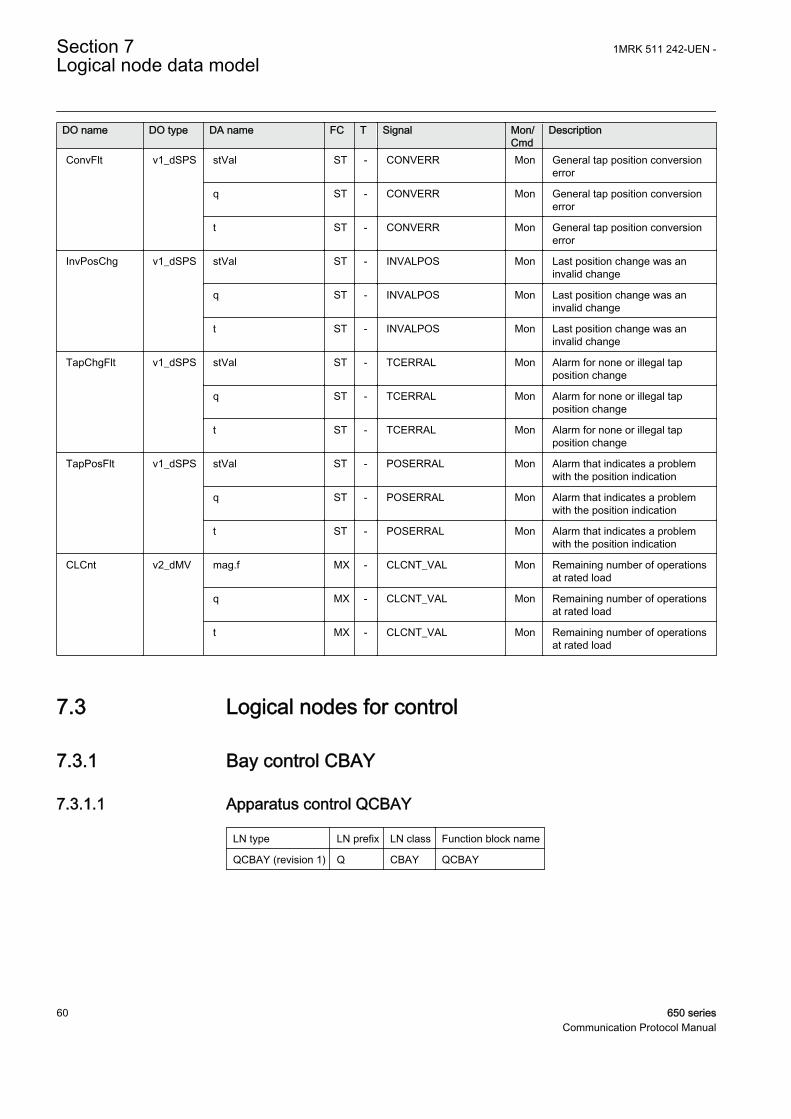
DO name DO type DA name FC T Signal Mon/Cmd
Description
ConvFlt v1_dSPS stVal ST - CONVERR Mon General tap position conversionerror
q ST - CONVERR Mon General tap position conversionerror
t ST - CONVERR Mon General tap position conversionerror
InvPosChg v1_dSPS stVal ST - INVALPOS Mon Last position change was aninvalid change
q ST - INVALPOS Mon Last position change was aninvalid change
t ST - INVALPOS Mon Last position change was aninvalid change
TapChgFlt v1_dSPS stVal ST - TCERRAL Mon Alarm for none or illegal tapposition change
q ST - TCERRAL Mon Alarm for none or illegal tapposition change
t ST - TCERRAL Mon Alarm for none or illegal tapposition change
TapPosFlt v1_dSPS stVal ST - POSERRAL Mon Alarm that indicates a problemwith the position indication
q ST - POSERRAL Mon Alarm that indicates a problemwith the position indication
t ST - POSERRAL Mon Alarm that indicates a problemwith the position indication
CLCnt v2_dMV mag.f MX - CLCNT_VAL Mon Remaining number of operationsat rated load
q MX - CLCNT_VAL Mon Remaining number of operationsat rated load
t MX - CLCNT_VAL Mon Remaining number of operationsat rated load
7.3 Logical nodes for control
7.3.1 Bay control CBAY
7.3.1.1 Apparatus control QCBAY
LN type LN prefix LN class Function block name
QCBAY (revision 1) Q CBAY QCBAY
Section 7 1MRK 511 242-UEN -Logical node data model
60 650 seriesCommunication Protocol Manual

Table 8: QCBAY Logical node data (instance 1)
DO name DO type DA name FC T Signal Mon/Cmd
Description
Mod a_dINC Oper.ctlVal CO - - Cmd Mode parameter
Oper.origin.orCat CO - - Cmd Mode parameter
Oper.origin.orIdent CO - - Cmd Mode parameter
Oper.ctlNum CO - - Cmd Mode parameter
Oper.T CO - - Cmd Mode parameter
Oper.Test CO - - Cmd Mode parameter
Oper.Check CO - - Cmd Mode parameter
stVal ST - - Mon Mode status parameter for 61850
q ST - - Mon Mode status parameter for 61850
t ST - - Mon Mode status parameter for 61850
Beh a_dINS stVal ST - Beh Mon Behaviour parameter for 61850
q ST - Beh Mon Behaviour parameter for 61850
t ST - Beh Mon Behaviour parameter for 61850
LocSwPos v1_dINS stVal ST - - Mon Position of the Local/Remoteswitch
q ST - - Mon Position of the Local/Remoteswitch
t ST - - Mon Position of the Local/Remoteswitch
SrcOpPrm v1_dINS stVal ST - PSTO Mon Value for the operator placeallocation
q ST - PSTO Mon Value for the operator placeallocation
t ST - PSTO Mon Value for the operator placeallocation
BlkCmd v1_dSPC Oper.ctlVal CO - - Cmd Special block command value
Oper.origin.orCat CO - - Cmd Special block command value
Oper.origin.orIdent CO - - Cmd Special block command value
Oper.ctlNum CO - - Cmd Special block command value
Oper.T CO - - Cmd Special block command value
Oper.Test CO - - Cmd Special block command value
Oper.Check CO - - Cmd Special block command value
stVal ST - CMD_BLKD Mon Function is blocked for commands
q ST - CMD_BLKD Mon Function is blocked for commands
t ST - CMD_BLKD Mon Function is blocked for commands
BlkUpd v1_dSPC Oper.ctlVal CO - - Cmd Special block command value
Oper.origin.orCat CO - - Cmd Special block command value
Oper.origin.orIdent CO - - Cmd Special block command value
Oper.ctlNum CO - - Cmd Special block command value
Oper.T CO - - Cmd Special block command value
Table continues on next page
1MRK 511 242-UEN - Section 7Logical node data model
650 series 61Communication Protocol Manual

DO name DO type DA name FC T Signal Mon/Cmd
Description
BlkUpd v1_dSPC Oper.Test CO - - Cmd Special block command value
Oper.Check CO - - Cmd Special block command value
stVal ST - UPD_BLKD Mon Update of position is blocked
q ST - UPD_BLKD Mon Update of position is blocked
t ST - UPD_BLKD Mon Update of position is blocked
BlkMeas v1_dSPS stVal ST - - Mon Update of measurand is blocked
q ST - - Mon Update of measurand is blocked
t ST - - Mon Update of measurand is blocked
Loc v1_dSPS stVal ST - LOC Mon Local operation allowed
q ST - LOC Mon Local operation allowed
t ST - LOC Mon Local operation allowed
Rem v1_dSPS stVal ST - REM Mon Remote operation allowed
q ST - REM Mon Remote operation allowed
t ST - REM Mon Remote operation allowed
7.3.2 Interlocking CILO
7.3.2.1 Interlocking SCILO
LN type LN prefix LN class Function block name
SCILO (revision 1) S CILO SCILO
Table 9: SCILO Logical node data (instance 0)
DO name DO type DA name FC T Signal Mon/Cmd
Description
Mod a_dINC Oper.ctlVal CO - - Cmd Mode parameter
Oper.origin.orCat CO - - Cmd Mode parameter
Oper.origin.orIdent CO - - Cmd Mode parameter
Oper.ctlNum CO - - Cmd Mode parameter
Oper.T CO - - Cmd Mode parameter
Oper.Test CO - - Cmd Mode parameter
Oper.Check CO - - Cmd Mode parameter
stVal ST - - Mon Mode status parameter for 61850
q ST - - Mon Mode status parameter for 61850
t ST - - Mon Mode status parameter for 61850
Beh a_dINS stVal ST - Beh Mon Behaviour parameter for 61850
q ST - Beh Mon Behaviour parameter for 61850
t ST - Beh Mon Behaviour parameter for 61850
Table continues on next page
Section 7 1MRK 511 242-UEN -Logical node data model
62 650 seriesCommunication Protocol Manual

DO name DO type DA name FC T Signal Mon/Cmd
Description
EnaCls a_dSPS stVal ST - EN_CLOSE Mon Close operation at open orintermediate or bad position isenabled
q ST - EN_CLOSE Mon Close operation at open orintermediate or bad position isenabled
t ST - EN_CLOSE Mon Close operation at open orintermediate or bad position isenabled
EnaOpn a_dSPS stVal ST - EN_OPEN Mon Open operation at closed orintermediate or bad position isenabled
q ST - EN_OPEN Mon Open operation at closed orintermediate or bad position isenabled
t ST - EN_OPEN Mon Open operation at closed orintermediate or bad position isenabled
7.3.3 Switch controller CSWI
7.3.3.1 Apparatus control SCSWI
LN type LN prefix LN class Function block name
SCSWI (revision 1) S CSWI SCSWI
Table 10: SCSWI Logical node data (instance 1)
DO name DO type DA name FC T Signal Mon/Cmd
Description
Pos a_dDPC Cancel.ctlVal CO - - Cmd Command parameter forIEC61850
Cancel.origin.orCat CO - - Cmd Command parameter forIEC61850
Oper.ctlVal CO - - Cmd Command parameter forIEC61850
Oper.origin.orCat CO - - Cmd Command parameter forIEC61850
SBOw.ctlVal CO - - Cmd Command parameter forIEC61850
SBOw.origin.orCat CO - - Cmd Command parameter forIEC61850
SBOw.origin.orIdent CO - - Cmd Command parameter forIEC61850
Oper.origin.orIdent CO - - Cmd Command parameter forIEC61850
Table continues on next page
1MRK 511 242-UEN - Section 7Logical node data model
650 series 63Communication Protocol Manual

DO name DO type DA name FC T Signal Mon/Cmd
Description
Pos a_dDPC Cancel.origin.orIdent CO - - Cmd Command parameter forIEC61850
Cancel.ctlNum CO - - Cmd Command parameter forIEC61850
Oper.ctlNum CO - - Cmd Command parameter forIEC61850
SBOw.ctlNum CO - - Cmd Command parameter forIEC61850
SBOw.T CO - - Cmd Command parameter forIEC61850
Cancel.T CO - - Cmd Command parameter forIEC61850
Oper.T CO - - Cmd Command parameter forIEC61850
Oper.Test CO - - Cmd Command parameter forIEC61850
Cancel.Test CO - - Cmd Command parameter forIEC61850
SBOw.Test CO - - Cmd Command parameter forIEC61850
Oper.Check CO - - Cmd Command parameter forIEC61850
SBOw.Check CO - - Cmd Command parameter forIEC61850
stVal ST - POSITION Mon Position indication
q ST - POSITION Mon Position indication
t ST - POSITION Mon Position indication
stSeld ST - SELECTED Mon Select conditions are fulfilled
subEna SV - - - Substitute enable
subVal SV - - - Substituted double position value
ctlModel CF - CtlModel - Specifies control model type
Mod a_dINC Oper.ctlVal CO - - Cmd Mode parameter for 61850
Oper.origin.orCat CO - - Cmd Mode parameter for 61850
Oper.origin.orIdent CO - - Cmd Mode parameter for 61850
Oper.ctlNum CO - - Cmd Mode parameter for 61850
Oper.T CO - - Cmd Mode parameter for 61850
Oper.Test CO - - Cmd Mode parameter for 61850
Oper.Check CO - - Cmd Mode parameter for 61850
stVal ST - - Mon Mode status value parameter for61850
q ST - - Mon Mode status value parameter for61850
t ST - - Mon Mode status value parameter for61850
Beh a_dINS stVal ST - Beh Mon Behaviour parameter for 61850
Table continues on next page
Section 7 1MRK 511 242-UEN -Logical node data model
64 650 seriesCommunication Protocol Manual

DO name DO type DA name FC T Signal Mon/Cmd
Description
Beh a_dINS q ST - Beh Mon Behaviour parameter for 61850
t ST - Beh Mon Behaviour parameter for 61850
OpCls b_dACT general ST T EXE_CL Mon Execute command for closedirection
q ST T EXE_CL Mon Execute command for closedirection
t ST T EXE_CL Mon Execute command for closedirection
OpOpn b_dACT general ST T EXE_OP Mon Execute command for opendirection
q ST T EXE_OP Mon Execute command for opendirection
t ST T EXE_OP Mon Execute command for opendirection
BlkCmd v1_dSPC Oper.ctlVal CO - - Cmd Special block command value
Oper.origin.orCat CO - - Cmd Special block command value
Oper.origin.orIdent CO - - Cmd Special block command value
Oper.ctlNum CO - - Cmd Special block command value
Oper.T CO - - Cmd Special block command value
Oper.Test CO - - Cmd Special block command value
Oper.Check CO - - Cmd Special block command value
stVal ST - CMD_BLK Mon Commands are blocked
q ST - CMD_BLK Mon Commands are blocked
t ST - CMD_BLK Mon Commands are blocked
7.4 Logical nodes for conversion functions
7.4.1 Integer to Boolean converter FCVB
7.4.1.1 Integer to Boolean 16 conversion with Logic Node representationIB16FCVB
LN type LN prefix LN class Function block name
IB16FCVB (revision 0) IB16 FCVB IB16FCVB
1MRK 511 242-UEN - Section 7Logical node data model
650 series 65Communication Protocol Manual

Table 11: IB16FCVB Logical node data (instance 1)
DO name DO type DA name FC T Signal Mon/Cmd
Description
Mod a_dINC Oper.ctlVal CO - - Cmd Mode parameter
Oper.origin.orCat CO - - Cmd Mode parameter
Oper.origin.orIdent CO - - Cmd Mode parameter
Oper.ctlNum CO - - Cmd Mode parameter
Oper.T CO - - Cmd Mode parameter
Oper.Test CO - - Cmd Mode parameter
Oper.Check CO - - Cmd Mode parameter
stVal ST - - Mon Mode status parameter for 61850
q ST - - Mon Mode status parameter for 61850
t ST - - Mon Mode status parameter for 61850
Beh a_dINS stVal ST - Beh Mon Behaviour parameter for 61850
q ST - Beh Mon Behaviour parameter for 61850
t ST - Beh Mon Behaviour parameter for 61850
ISCSO b_dINC Oper.ctlVal CO - - Cmd Command parameter forIEC61850
Oper.origin.orCat CO - - Cmd Command parameter forIEC61850
Oper.origin.orIdent CO - - Cmd Command parameter forIEC61850
Oper.ctlNum CO - - Cmd Command parameter forIEC61850
Oper.T CO - - Cmd Command parameter forIEC61850
Oper.Test CO - - Cmd Command parameter forIEC61850
Oper.Check CO - - Cmd Command parameter forIEC61850
stVal ST - - Mon Integer to be converted to bitpattern OUT1 to OUT16
q ST - - Mon Integer to be converted to bitpattern OUT1 to OUT16
t ST - - Mon Integer to be converted to bitpattern OUT1 to OUT16
ctlModel CF - - - Used by CH
7.4.2 Boolean to integer converter FCVI
7.4.2.1 Boolean 16 to Integer conversion with Logic Node representationB16IFCVI
LN type LN prefix LN class Function block name
B16IFCVI (revision 0) B16I FCVI B16IFCVI
Section 7 1MRK 511 242-UEN -Logical node data model
66 650 seriesCommunication Protocol Manual

Table 12: B16IFCVI Logical node data (instance 1)
DO name DO type DA name FC T Signal Mon/Cmd
Description
Mod a_dINC Oper.ctlVal CO - - Cmd Mode parameter
Oper.origin.orCat CO - - Cmd Mode parameter
Oper.origin.orIdent CO - - Cmd Mode parameter
Oper.ctlNum CO - - Cmd Mode parameter
Oper.T CO - - Cmd Mode parameter
Oper.Test CO - - Cmd Mode parameter
Oper.Check CO - - Cmd Mode parameter
stVal ST - - Mon Mode status parameter for 61850
q ST - - Mon Mode status parameter for 61850
t ST - - Mon Mode status parameter for 61850
Beh a_dINS stVal ST - Beh Mon Behaviour parameter for 61850
q ST - Beh Mon Behaviour parameter for 61850
t ST - Beh Mon Behaviour parameter for 61850
OutInt b_dINS stVal ST - OUT Mon Output value
q ST - OUT Mon Output value
t ST - OUT Mon Output value
7.5 Logical nodes for protection functions
7.5.1 Differential protection PDIF
7.5.1.1 Transformer differential protection, two winding T2WPDIF
LN type LN prefix LN class Function block name
T2WPDIF (revision 2) T2W PDIF T2WPDIF
Table 13: T2WPDIF Logical node data (instance 0)
DO name DO type DA name FC T Signal Mon/Cmd
Description
Str a_dACD general ST - START Mon General start signal
phsA ST - STL1 Mon Start signal from phase L1
phsB ST - STL2 Mon Start signal from phase L2
phsC ST - STL3 Mon Start signal from phase L3
q ST - START Mon General start signal
t ST - START Mon General start signal
Mod a_dINC Oper.ctlVal CO - - Cmd Mode parameter
Table continues on next page
1MRK 511 242-UEN - Section 7Logical node data model
650 series 67Communication Protocol Manual

DO name DO type DA name FC T Signal Mon/Cmd
Description
Mod a_dINC Oper.origin.orCat CO - - Cmd Mode parameter
Oper.origin.orIdent CO - - Cmd Mode parameter
Oper.ctlNum CO - - Cmd Mode parameter
Oper.T CO - - Cmd Mode parameter
Oper.Test CO - - Cmd Mode parameter
Oper.Check CO - - Cmd Mode parameter
stVal ST - - Mon Mode status parameter for 61850
q ST - - Mon Mode status parameter for 61850
t ST - - Mon Mode status parameter for 61850
Beh a_dINS stVal ST - Beh Mon Behaviour parameter for 61850
q ST - Beh Mon Behaviour parameter for 61850
t ST - Beh Mon Behaviour parameter for 61850
Op b_dACT general ST T TRIP Mon General trip signal
q ST T TRIP Mon General trip signal
t ST T TRIP Mon General trip signal
OpRst v1_dSPS stVal ST - TRIPRES Mon Trip signal from restraineddifferential protection
q ST - TRIPRES Mon Trip signal from restraineddifferential protection
t ST - TRIPRES Mon Trip signal from restraineddifferential protection
OpNSSen v1_dSPS stVal ST - TRNSSENS Mon Trip signal from sensitivenegative sequence differentialprotection
q ST - TRNSSENS Mon Trip signal from sensitivenegative sequence differentialprotection
t ST - TRNSSENS Mon Trip signal from sensitivenegative sequence differentialprotection
OpNSUnRst v1_dSPS stVal ST - TRNSUNR Mon Trip signal from unrestrainednegative sequence differentialprotection
q ST - TRNSUNR Mon Trip signal from unrestrainednegative sequence differentialprotection
t ST - TRNSUNR Mon Trip signal from unrestrainednegative sequence differentialprotection
OpUnRst v1_dSPS stVal ST - TRIPUNRE Mon Trip signal from unrestraineddifferential protection
q ST - TRIPUNRE Mon Trip signal from unrestraineddifferential protection
t ST - TRIPUNRE Mon Trip signal from unrestraineddifferential protection
Table continues on next page
Section 7 1MRK 511 242-UEN -Logical node data model
68 650 seriesCommunication Protocol Manual

DO name DO type DA name FC T Signal Mon/Cmd
Description
Blk2H v1_dSPS stVal ST - BLK2H Mon General second harmonic blocksignal
q ST - BLK2H Mon General second harmonic blocksignal
t ST - BLK2H Mon General second harmonic blocksignal
Blk5H v1_dSPS stVal ST - BLK5H Mon General fifth harmonic block signal
q ST - BLK5H Mon General fifth harmonic block signal
t ST - BLK5H Mon General fifth harmonic block signal
BlkWav v1_dSPS stVal ST - BLKWAV Mon General block signal fromwaveform criteria
q ST - BLKWAV Mon General block signal fromwaveform criteria
t ST - BLKWAV Mon General block signal fromwaveform criteria
ExFlt v1_dSPS stVal ST - - Mon Indication that external fault/disturbance has been detected
q ST - - Mon Indication that external fault/disturbance has been detected
t ST - - Mon Indication that external fault/disturbance has been detected
ItrFlt v1_dSPS stVal ST - - Mon Indication that internal fault hasbeen detected
q ST - - Mon Indication that internal fault hasbeen detected
t ST - - Mon Indication that internal fault hasbeen detected
DifAlm v1_dSPS stVal ST - IDALARM Mon General alarm for sustaineddifferential currents
q ST - IDALARM Mon General alarm for sustaineddifferential currents
t ST - IDALARM Mon General alarm for sustaineddifferential currents
7.5.1.2 Transformer differential protection, three winding T3WPDIF
LN type LN prefix LN class Function block name
T3WPDIF (revision 2) T3W PDIF T3WPDIF
1MRK 511 242-UEN - Section 7Logical node data model
650 series 69Communication Protocol Manual

Table 14: T3WPDIF Logical node data (instance 0)
DO name DO type DA name FC T Signal Mon/Cmd
Description
Str a_dACD general ST - START Mon General start signal
phsA ST - STL1 Mon Start signal from phase L1
phsB ST - STL2 Mon Start signal from phase L2
phsC ST - STL3 Mon Start signal from phase L3
q ST - START Mon General start signal
t ST - START Mon General start signal
Mod a_dINC Oper.ctlVal CO - - Cmd Mode parameter
Oper.origin.orCat CO - - Cmd Mode parameter
Oper.origin.orIdent CO - - Cmd Mode parameter
Oper.ctlNum CO - - Cmd Mode parameter
Oper.T CO - - Cmd Mode parameter
Oper.Test CO - - Cmd Mode parameter
Oper.Check CO - - Cmd Mode parameter
stVal ST - - Mon Mode status parameter for 61850
q ST - - Mon Mode status parameter for 61850
t ST - - Mon Mode status parameter for 61850
Beh a_dINS stVal ST - Beh Mon Behaviour parameter for 61850
q ST - Beh Mon Behaviour parameter for 61850
t ST - Beh Mon Behaviour parameter for 61850
Op b_dACT general ST T TRIP Mon General trip signal
q ST T TRIP Mon General trip signal
t ST T TRIP Mon General trip signal
OpRst v1_dSPS stVal ST - TRIPRES Mon Trip signal from restraineddifferential protection
q ST - TRIPRES Mon Trip signal from restraineddifferential protection
t ST - TRIPRES Mon Trip signal from restraineddifferential protection
OpNSSen v1_dSPS stVal ST - TRNSSENS Mon Trip signal from sensitivenegative sequence differentialprotection
q ST - TRNSSENS Mon Trip signal from sensitivenegative sequence differentialprotection
t ST - TRNSSENS Mon Trip signal from sensitivenegative sequence differentialprotection
OpNSUnRst v1_dSPS stVal ST - TRNSUNR Mon Trip signal from unrestrainednegative sequence differentialprotection
q ST - TRNSUNR Mon Trip signal from unrestrainednegative sequence differentialprotection
Table continues on next page
Section 7 1MRK 511 242-UEN -Logical node data model
70 650 seriesCommunication Protocol Manual

DO name DO type DA name FC T Signal Mon/Cmd
Description
OpNSUnRst v1_dSPS t ST - TRNSUNR Mon Trip signal from unrestrainednegative sequence differentialprotection
OpUnRst v1_dSPS stVal ST - TRIPUNRE Mon Trip signal from unrestraineddifferential protection
q ST - TRIPUNRE Mon Trip signal from unrestraineddifferential protection
t ST - TRIPUNRE Mon Trip signal from unrestraineddifferential protection
Blk2H v1_dSPS stVal ST - BLK2H Mon General second harmonic blocksignal
q ST - BLK2H Mon General second harmonic blocksignal
t ST - BLK2H Mon General second harmonic blocksignal
Blk5H v1_dSPS stVal ST - BLK5H Mon General fifth harmonic block signal
q ST - BLK5H Mon General fifth harmonic block signal
t ST - BLK5H Mon General fifth harmonic block signal
BlkWav v1_dSPS stVal ST - BLKWAV Mon General block signal fromwaveform criteria
q ST - BLKWAV Mon General block signal fromwaveform criteria
t ST - BLKWAV Mon General block signal fromwaveform criteria
ExFlt v1_dSPS stVal ST - - Mon Indication that external fault/disturbance has been detected
q ST - - Mon Indication that external fault/disturbance has been detected
t ST - - Mon Indication that external fault/disturbance has been detected
ItrFlt v1_dSPS stVal ST - - Mon Indication that internal fault hasbeen detected
q ST - - Mon Indication that internal fault hasbeen detected
t ST - - Mon Indication that internal fault hasbeen detected
DifAlm v1_dSPS stVal ST - IDALARM Mon General alarm for sustaineddifferential currents
q ST - IDALARM Mon General alarm for sustaineddifferential currents
t ST - IDALARM Mon General alarm for sustaineddifferential currents
7.5.1.3 Restricted earth fault protection, low impedance REFPDIF
LN type LN prefix LN class Function block name
REFPDIF (revision 1) REF PDIF REFPDIF
1MRK 511 242-UEN - Section 7Logical node data model
650 series 71Communication Protocol Manual

Table 15: REFPDIF Logical node data (instance 0)
DO name DO type DA name FC T Signal Mon/Cmd
Description
Mod a_dINC Oper.ctlVal CO - - Cmd Mode parameter
Oper.origin.orCat CO - - Cmd Mode parameter
Oper.origin.orIdent CO - - Cmd Mode parameter
Oper.ctlNum CO - - Cmd Mode parameter
Oper.T CO - - Cmd Mode parameter
Oper.Test CO - - Cmd Mode parameter
Oper.Check CO - - Cmd Mode parameter
stVal ST - - Mon Mode status parameter for 61850
q ST - - Mon Mode status parameter for 61850
t ST - - Mon Mode status parameter for 61850
Beh a_dINS stVal ST - Beh Mon Behaviour parameter for 61850
q ST - Beh Mon Behaviour parameter for 61850
t ST - Beh Mon Behaviour parameter for 61850
Str b_dACD general ST - START Mon General start signal
q ST - START Mon General start signal
t ST - START Mon General start signal
Op b_dACT general ST T TRIP Mon General trip signal
q ST T TRIP Mon General trip signal
t ST T TRIP Mon General trip signal
Blk2H v1_dSPS stVal ST - BLK2H Mon Block due to 2-nd harmonic
q ST - BLK2H Mon Block due to 2-nd harmonic
t ST - BLK2H Mon Block due to 2-nd harmonic
ItrFlt v1_dSPS stVal ST - DIROK Mon Directional criteria has operatedfor internal fault
q ST - DIROK Mon Directional criteria has operatedfor internal fault
t ST - DIROK Mon Directional criteria has operatedfor internal fault
7.5.1.4 Generator differential protection GENPDIF
LN type LN prefix LN class Function block name
GENPDIF (revision 1) GEN PDIF GENPDIF
Section 7 1MRK 511 242-UEN -Logical node data model
72 650 seriesCommunication Protocol Manual
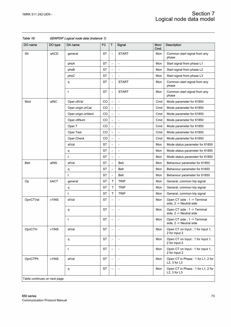
Table 16: GENPDIF Logical node data (instance 1)
DO name DO type DA name FC T Signal Mon/Cmd
Description
Str aACD general ST - START Mon Common start signal from anyphase
phsA ST - - Mon Start signal from phase L1
phsB ST - - Mon Start signal from phase L2
phsC ST - - Mon Start signal from phase L3
q ST - START Mon Common start signal from anyphase
t ST - START Mon Common start signal from anyphase
Mod aINC Oper.ctlVal CO - - Cmd Mode parameter for 61850
Oper.origin.orCat CO - - Cmd Mode parameter for 61850
Oper.origin.orIdent CO - - Cmd Mode parameter for 61850
Oper.ctlNum CO - - Cmd Mode parameter for 61850
Oper.T CO - - Cmd Mode parameter for 61850
Oper.Test CO - - Cmd Mode parameter for 61850
Oper.Check CO - - Cmd Mode parameter for 61850
stVal ST - - Mon Mode status parameter for 61850
q ST - - Mon Mode status parameter for 61850
t ST - - Mon Mode status parameter for 61850
Beh aINS stVal ST - Beh Mon Behaviour parameter for 61850
q ST - Beh Mon Behaviour parameter for 61850
t ST - Beh Mon Behaviour parameter for 61850
Op bACT general ST T TRIP Mon General, common trip signal
q ST T TRIP Mon General, common trip signal
t ST T TRIP Mon General, common trip signal
OpnCTVal v1INS stVal ST - - Mon Open CT side : 1 -> Terminalside, 2 -> Neutral side
q ST - - Mon Open CT side : 1 -> Terminalside, 2 -> Neutral side
t ST - - Mon Open CT side : 1 -> Terminalside, 2 -> Neutral side
OpnCTIn v1INS stVal ST - - Mon Open CT on Input : 1 for input 1,2 for input 2
q ST - - Mon Open CT on Input : 1 for input 1,2 for input 2
t ST - - Mon Open CT on Input : 1 for input 1,2 for input 2
OpnCTPh v1INS stVal ST - - Mon Open CT in Phase : 1 for L1, 2 forL2, 3 for L3
q ST - - Mon Open CT in Phase : 1 for L1, 2 forL2, 3 for L3
Table continues on next page
1MRK 511 242-UEN - Section 7Logical node data model
650 series 73Communication Protocol Manual

DO name DO type DA name FC T Signal Mon/Cmd
Description
OpnCTPh v1INS t ST - - Mon Open CT in Phase : 1 for L1, 2 forL2, 3 for L3
OpRst v1SPS stVal ST - TRIPRES Mon Trip signal from restraineddifferential protection
q ST - TRIPRES Mon Trip signal from restraineddifferential protection
t ST - TRIPRES Mon Trip signal from restraineddifferential protection
OpUnRst v1SPS stVal ST - TRIPUNRE Mon Trip signal from unrestraineddifferential protection
q ST - TRIPUNRE Mon Trip signal from unrestraineddifferential protection
t ST - TRIPUNRE Mon Trip signal from unrestraineddifferential protection
OpNSUnRst v1SPS stVal ST - TRNSUNR Mon Trip signal from unrestr. neg. seq.diff. protection
q ST - TRNSUNR Mon Trip signal from unrestr. neg. seq.diff. protection
t ST - TRNSUNR Mon Trip signal from unrestr. neg. seq.diff. protection
OpNSSen v1SPS stVal ST - TRNSSENS Mon Trip signal from sensitive neg.seq. diff. protection
q ST - TRNSSENS Mon Trip signal from sensitive neg.seq. diff. protection
t ST - TRNSSENS Mon Trip signal from sensitive neg.seq. diff. protection
ItrFlt v1SPS stVal ST - - Mon Indication that internal fault hasbeen detected
q ST - - Mon Indication that internal fault hasbeen detected
t ST - - Mon Indication that internal fault hasbeen detected
ExFlt v1SPS stVal ST - - Mon Indication that external fault/disturbance has been detected
q ST - - Mon Indication that external fault/disturbance has been detected
t ST - - Mon Indication that external fault/disturbance has been detected
BlkH v1SPS stVal ST - BLKH Mon Common harmonic block signal
q ST - BLKH Mon Common harmonic block signal
t ST - BLKH Mon Common harmonic block signal
BlkHPhA v1SPS stVal ST - - Mon Harmonic block signal, phase L1
q ST - - Mon Harmonic block signal, phase L1
t ST - - Mon Harmonic block signal, phase L1
BlkHPhB v1SPS stVal ST - - Mon Harmonic block signal, phase L2
q ST - - Mon Harmonic block signal, phase L2
Table continues on next page
Section 7 1MRK 511 242-UEN -Logical node data model
74 650 seriesCommunication Protocol Manual

DO name DO type DA name FC T Signal Mon/Cmd
Description
BlkHPhB v1SPS t ST - - Mon Harmonic block signal, phase L2
BlkHPhC v1SPS stVal ST - - Mon Harmonic block signal, phase L3
q ST - - Mon Harmonic block signal, phase L3
t ST - - Mon Harmonic block signal, phase L3
OpnCT v1SPS stVal ST - OPENCT Mon An open CT was detected
q ST - OPENCT Mon An open CT was detected
t ST - OPENCT Mon An open CT was detected
OpnCTAlm v1SPS stVal ST - OPENCTAL Mon Open CT Alarm output signal.Issued after a delay ...
q ST - OPENCTAL Mon Open CT Alarm output signal.Issued after a delay ...
t ST - OPENCTAL Mon Open CT Alarm output signal.Issued after a delay ...
DifANS v2MV mag.f MX - IDNSMAG Mon Negative Sequence Differentialcurrent; in primary Amperes
q MX - IDNSMAG Mon Negative Sequence Differentialcurrent; in primary Amperes
t MX - IDNSMAG Mon Negative Sequence Differentialcurrent; in primary Amperes
RstMaxA v2MV mag.f MX - IBIAS Mon Magnitude of the common Biascurrent; in primary Amperes
q MX - IBIAS Mon Magnitude of the common Biascurrent; in primary Amperes
t MX - IBIAS Mon Magnitude of the common Biascurrent; in primary Amperes
7.5.1.5 1 Ph High impedance differential protection HZPDIF
LN type LN prefix LN class Function block name
HZPDIF (revision 1) HZ PDIF HZPDIF
Table 17: HZPDIF Logical node data (instance 1)
DO name DO type DA name FC T Signal Mon/Cmd
Description
Mod a_dINC Oper.ctlVal CO - - Cmd Mode parameter
Oper.origin.orCat CO - - Cmd Mode parameter
Oper.origin.orIdent CO - - Cmd Mode parameter
Oper.ctlNum CO - - Cmd Mode parameter
Oper.T CO - - Cmd Mode parameter
Oper.Test CO - - Cmd Mode parameter
Oper.Check CO - - Cmd Mode parameter
stVal ST - - Mon Mode status parameter for 61850
Table continues on next page
1MRK 511 242-UEN - Section 7Logical node data model
650 series 75Communication Protocol Manual
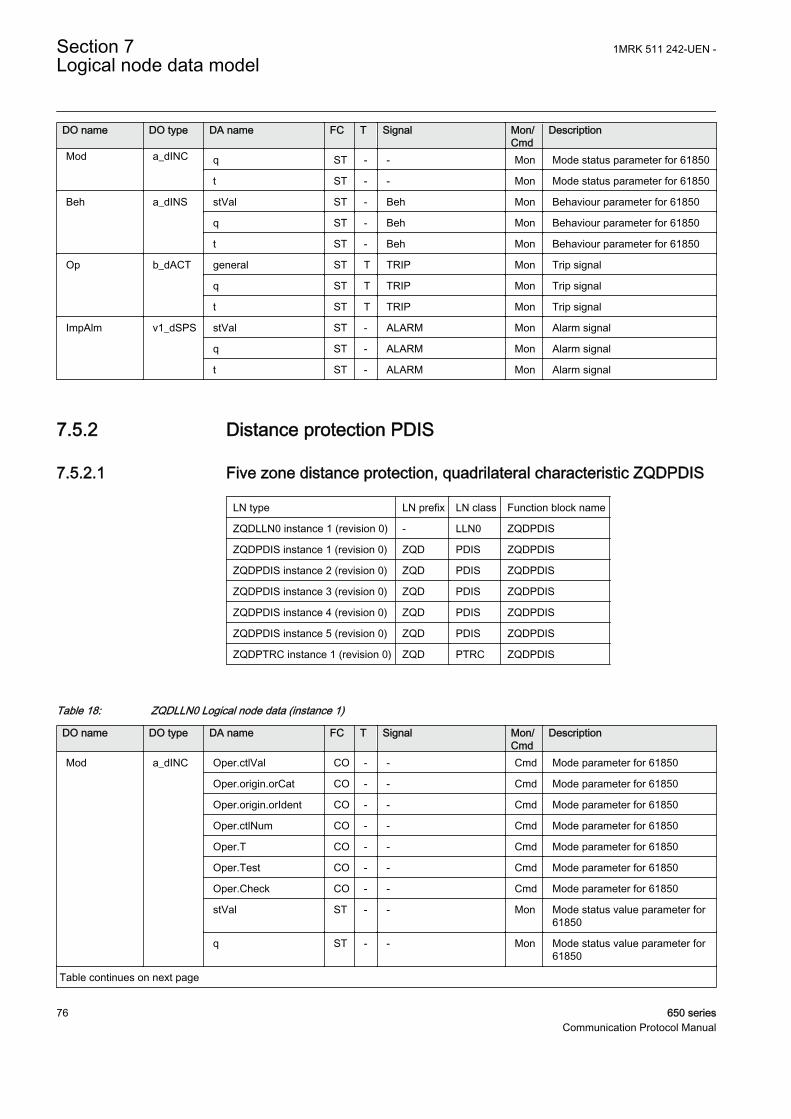
DO name DO type DA name FC T Signal Mon/Cmd
Description
Mod a_dINC q ST - - Mon Mode status parameter for 61850
t ST - - Mon Mode status parameter for 61850
Beh a_dINS stVal ST - Beh Mon Behaviour parameter for 61850
q ST - Beh Mon Behaviour parameter for 61850
t ST - Beh Mon Behaviour parameter for 61850
Op b_dACT general ST T TRIP Mon Trip signal
q ST T TRIP Mon Trip signal
t ST T TRIP Mon Trip signal
ImpAlm v1_dSPS stVal ST - ALARM Mon Alarm signal
q ST - ALARM Mon Alarm signal
t ST - ALARM Mon Alarm signal
7.5.2 Distance protection PDIS
7.5.2.1 Five zone distance protection, quadrilateral characteristic ZQDPDIS
LN type LN prefix LN class Function block name
ZQDLLN0 instance 1 (revision 0) - LLN0 ZQDPDIS
ZQDPDIS instance 1 (revision 0) ZQD PDIS ZQDPDIS
ZQDPDIS instance 2 (revision 0) ZQD PDIS ZQDPDIS
ZQDPDIS instance 3 (revision 0) ZQD PDIS ZQDPDIS
ZQDPDIS instance 4 (revision 0) ZQD PDIS ZQDPDIS
ZQDPDIS instance 5 (revision 0) ZQD PDIS ZQDPDIS
ZQDPTRC instance 1 (revision 0) ZQD PTRC ZQDPDIS
Table 18: ZQDLLN0 Logical node data (instance 1)
DO name DO type DA name FC T Signal Mon/Cmd
Description
Mod a_dINC Oper.ctlVal CO - - Cmd Mode parameter for 61850
Oper.origin.orCat CO - - Cmd Mode parameter for 61850
Oper.origin.orIdent CO - - Cmd Mode parameter for 61850
Oper.ctlNum CO - - Cmd Mode parameter for 61850
Oper.T CO - - Cmd Mode parameter for 61850
Oper.Test CO - - Cmd Mode parameter for 61850
Oper.Check CO - - Cmd Mode parameter for 61850
stVal ST - - Mon Mode status value parameter for61850
q ST - - Mon Mode status value parameter for61850
Table continues on next page
Section 7 1MRK 511 242-UEN -Logical node data model
76 650 seriesCommunication Protocol Manual
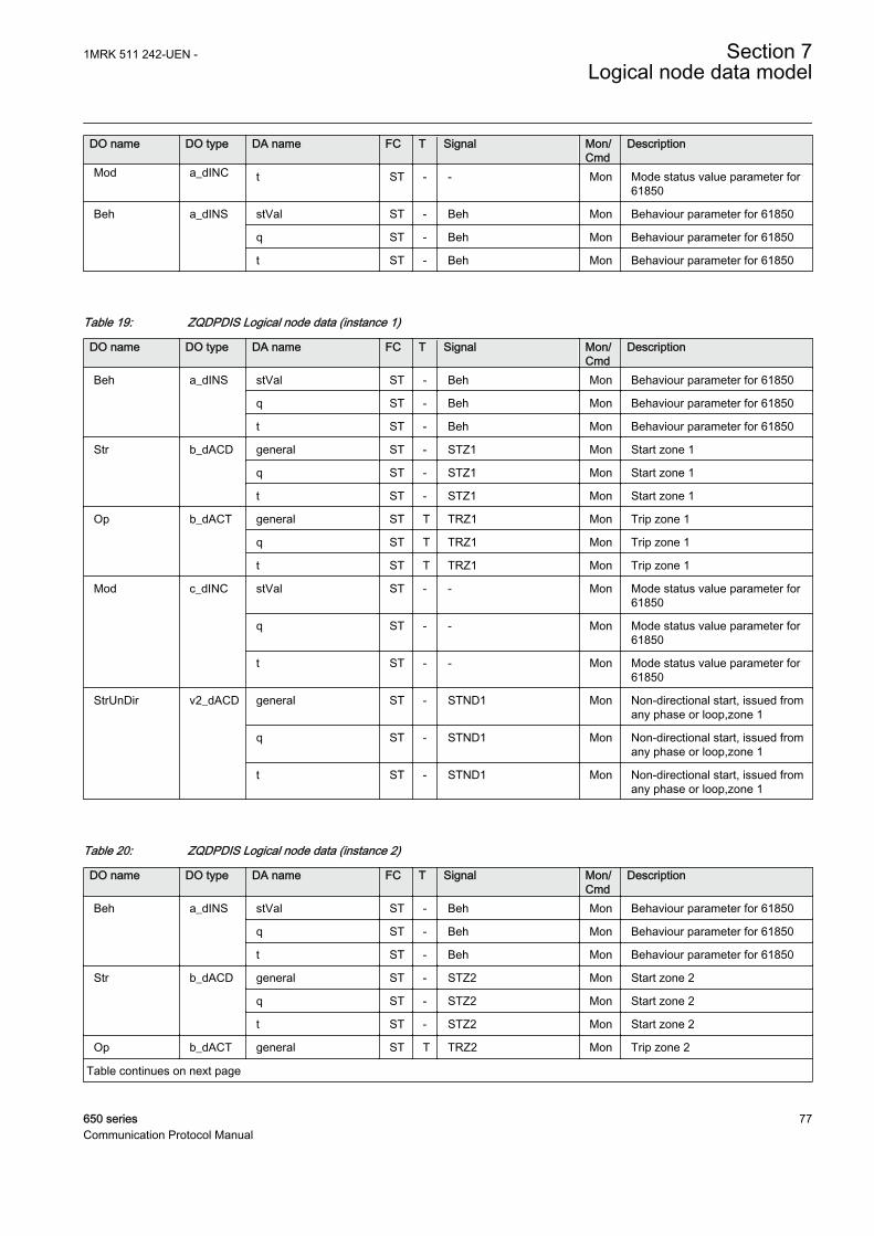
DO name DO type DA name FC T Signal Mon/Cmd
Description
Mod a_dINC t ST - - Mon Mode status value parameter for61850
Beh a_dINS stVal ST - Beh Mon Behaviour parameter for 61850
q ST - Beh Mon Behaviour parameter for 61850
t ST - Beh Mon Behaviour parameter for 61850
Table 19: ZQDPDIS Logical node data (instance 1)
DO name DO type DA name FC T Signal Mon/Cmd
Description
Beh a_dINS stVal ST - Beh Mon Behaviour parameter for 61850
q ST - Beh Mon Behaviour parameter for 61850
t ST - Beh Mon Behaviour parameter for 61850
Str b_dACD general ST - STZ1 Mon Start zone 1
q ST - STZ1 Mon Start zone 1
t ST - STZ1 Mon Start zone 1
Op b_dACT general ST T TRZ1 Mon Trip zone 1
q ST T TRZ1 Mon Trip zone 1
t ST T TRZ1 Mon Trip zone 1
Mod c_dINC stVal ST - - Mon Mode status value parameter for61850
q ST - - Mon Mode status value parameter for61850
t ST - - Mon Mode status value parameter for61850
StrUnDir v2_dACD general ST - STND1 Mon Non-directional start, issued fromany phase or loop,zone 1
q ST - STND1 Mon Non-directional start, issued fromany phase or loop,zone 1
t ST - STND1 Mon Non-directional start, issued fromany phase or loop,zone 1
Table 20: ZQDPDIS Logical node data (instance 2)
DO name DO type DA name FC T Signal Mon/Cmd
Description
Beh a_dINS stVal ST - Beh Mon Behaviour parameter for 61850
q ST - Beh Mon Behaviour parameter for 61850
t ST - Beh Mon Behaviour parameter for 61850
Str b_dACD general ST - STZ2 Mon Start zone 2
q ST - STZ2 Mon Start zone 2
t ST - STZ2 Mon Start zone 2
Op b_dACT general ST T TRZ2 Mon Trip zone 2
Table continues on next page
1MRK 511 242-UEN - Section 7Logical node data model
650 series 77Communication Protocol Manual

DO name DO type DA name FC T Signal Mon/Cmd
Description
Op b_dACT q ST T TRZ2 Mon Trip zone 2
t ST T TRZ2 Mon Trip zone 2
Mod c_dINC stVal ST - - Mon Mode status value parameter for61850
q ST - - Mon Mode status value parameter for61850
t ST - - Mon Mode status value parameter for61850
StrUnDir v2_dACD general ST - STND2 Mon Non-directional start, issued fromany phase or loop, zone 2
q ST - STND2 Mon Non-directional start, issued fromany phase or loop, zone 2
t ST - STND2 Mon Non-directional start, issued fromany phase or loop, zone 2
Table 21: ZQDPDIS Logical node data (instance 3)
DO name DO type DA name FC T Signal Mon/Cmd
Description
Beh a_dINS stVal ST - Beh Mon Behaviour parameter for 61850
q ST - Beh Mon Behaviour parameter for 61850
t ST - Beh Mon Behaviour parameter for 61850
Str b_dACD general ST - STZ3 Mon Start zone 3
q ST - STZ3 Mon Start zone 3
t ST - STZ3 Mon Start zone 3
Op b_dACT general ST T TRZ3 Mon Trip zone 3
q ST T TRZ3 Mon Trip zone 3
t ST T TRZ3 Mon Trip zone 3
Mod c_dINC stVal ST - - Mon Mode status value parameter for61850
q ST - - Mon Mode status value parameter for61850
t ST - - Mon Mode status value parameter for61850
StrUnDir v2_dACD general ST - STND3 Mon Non-directional start, issued fromany phase or loop,zone 3
q ST - STND3 Mon Non-directional start, issued fromany phase or loop,zone 3
t ST - STND3 Mon Non-directional start, issued fromany phase or loop,zone 3
Section 7 1MRK 511 242-UEN -Logical node data model
78 650 seriesCommunication Protocol Manual
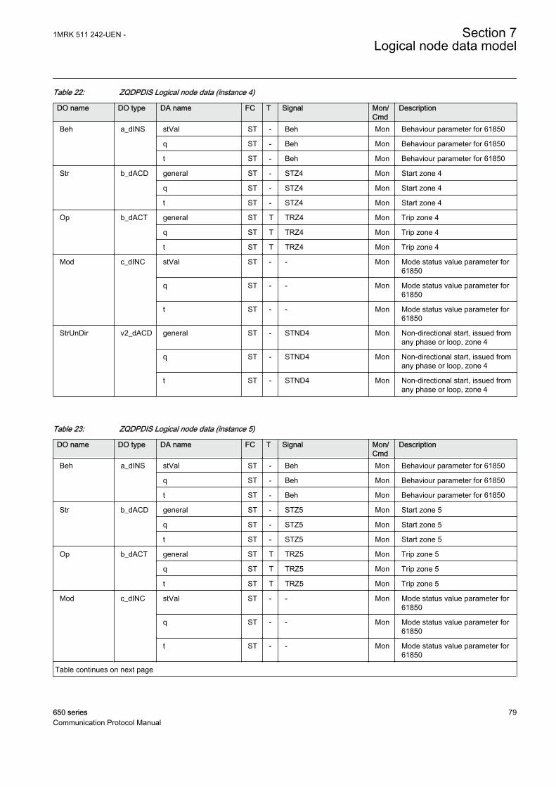
Table 22: ZQDPDIS Logical node data (instance 4)
DO name DO type DA name FC T Signal Mon/Cmd
Description
Beh a_dINS stVal ST - Beh Mon Behaviour parameter for 61850
q ST - Beh Mon Behaviour parameter for 61850
t ST - Beh Mon Behaviour parameter for 61850
Str b_dACD general ST - STZ4 Mon Start zone 4
q ST - STZ4 Mon Start zone 4
t ST - STZ4 Mon Start zone 4
Op b_dACT general ST T TRZ4 Mon Trip zone 4
q ST T TRZ4 Mon Trip zone 4
t ST T TRZ4 Mon Trip zone 4
Mod c_dINC stVal ST - - Mon Mode status value parameter for61850
q ST - - Mon Mode status value parameter for61850
t ST - - Mon Mode status value parameter for61850
StrUnDir v2_dACD general ST - STND4 Mon Non-directional start, issued fromany phase or loop, zone 4
q ST - STND4 Mon Non-directional start, issued fromany phase or loop, zone 4
t ST - STND4 Mon Non-directional start, issued fromany phase or loop, zone 4
Table 23: ZQDPDIS Logical node data (instance 5)
DO name DO type DA name FC T Signal Mon/Cmd
Description
Beh a_dINS stVal ST - Beh Mon Behaviour parameter for 61850
q ST - Beh Mon Behaviour parameter for 61850
t ST - Beh Mon Behaviour parameter for 61850
Str b_dACD general ST - STZ5 Mon Start zone 5
q ST - STZ5 Mon Start zone 5
t ST - STZ5 Mon Start zone 5
Op b_dACT general ST T TRZ5 Mon Trip zone 5
q ST T TRZ5 Mon Trip zone 5
t ST T TRZ5 Mon Trip zone 5
Mod c_dINC stVal ST - - Mon Mode status value parameter for61850
q ST - - Mon Mode status value parameter for61850
t ST - - Mon Mode status value parameter for61850
Table continues on next page
1MRK 511 242-UEN - Section 7Logical node data model
650 series 79Communication Protocol Manual

DO name DO type DA name FC T Signal Mon/Cmd
Description
StrUnDir v2_dACD general ST - STND5 Mon Non-directional start, issued fromany phase or loop, zone 5
q ST - STND5 Mon Non-directional start, issued fromany phase or loop, zone 5
t ST - STND5 Mon Non-directional start, issued fromany phase or loop, zone 5
Table 24: ZQDPTRC Logical node data (instance 1)
DO name DO type DA name FC T Signal Mon/Cmd
Description
Beh a_dINS stVal ST - Beh Mon Behaviour parameter for 61850
q ST - Beh Mon Behaviour parameter for 61850
t ST - Beh Mon Behaviour parameter for 61850
Str b_dACD general ST - START Mon General start signal
q ST - START Mon General start signal
t ST - START Mon General start signal
Op b_dACT general ST T TRIP Mon General trip signal
q ST T TRIP Mon General trip signal
t ST T TRIP Mon General trip signal
Mod c_dINC stVal ST - - Mon Mode status value parameter for61850
q ST - - Mon Mode status value parameter for61850
t ST - - Mon Mode status value parameter for61850
7.5.2.2 Phase selection with load enchroachment, quadrilateral characteristicFDPSPDIS
LN type LN prefix LN class Function block name
FDPSPDIS (revision 1) FDPS PDIS FDPSPDIS
Table 25: FDPSPDIS Logical node data (instance 0)
DO name DO type DA name FC T Signal Mon/Cmd
Description
Mod a_dINC Oper.ctlVal CO - - Cmd Mode parameter for 61850
Oper.origin.orCat CO - - Cmd Mode parameter for 61850
Oper.origin.orIdent CO - - Cmd Mode parameter for 61850
Oper.ctlNum CO - - Cmd Mode parameter for 61850
Oper.T CO - - Cmd Mode parameter for 61850
Table continues on next page
Section 7 1MRK 511 242-UEN -Logical node data model
80 650 seriesCommunication Protocol Manual

DO name DO type DA name FC T Signal Mon/Cmd
Description
Mod a_dINC Oper.Test CO - - Cmd Mode parameter for 61850
Oper.Check CO - - Cmd Mode parameter for 61850
stVal ST - - Mon Mode status value parameter for61850
q ST - - Mon Mode status value parameter for61850
t ST - - Mon Mode status value parameter for61850
Beh a_dINS stVal ST - Beh Mon Behaviour parameter for 61850
q ST - Beh Mon Behaviour parameter for 61850
t ST - Beh Mon Behaviour parameter for 61850
Str b_dACD general ST - START Mon Start in any phase or loop
q ST - START Mon Start in any phase or loop
t ST - START Mon Start in any phase or loop
Op b_dACT general ST T TRIP Mon Trip output
q ST T TRIP Mon Trip output
t ST T TRIP Mon Trip output
StrCndZ v1_dINS stVal ST - STCNDZI Mon Start condition (Z< with LE and/orI> and 3I0 E/F detection)
q ST - STCNDZI Mon Start condition (Z< with LE and/orI> and 3I0 E/F detection)
t ST - STCNDZI Mon Start condition (Z< with LE and/orI> and 3I0 E/F detection)
StrCndA v1_dINS stVal ST - STCNDLE Mon Start condition (only LE and 3I0 E/F detection)
q ST - STCNDLE Mon Start condition (only LE and 3I0 E/F detection)
t ST - STCNDLE Mon Start condition (only LE and 3I0 E/F detection)
StrFwdPhA v1_dSPS stVal ST - STFWL1 Mon Fault detected in phase L1 -forward direction
q ST - STFWL1 Mon Fault detected in phase L1 -forward direction
t ST - STFWL1 Mon Fault detected in phase L1 -forward direction
StrFwdPhB v1_dSPS stVal ST - STFWL2 Mon Fault detected in phase L2 -forward direction
q ST - STFWL2 Mon Fault detected in phase L2 -forward direction
t ST - STFWL2 Mon Fault detected in phase L2 -forward direction
StrFwdPhC v1_dSPS stVal ST - STFWL3 Mon Fault detected in phase L3 -forward direction
q ST - STFWL3 Mon Fault detected in phase L3 -forward direction
Table continues on next page
1MRK 511 242-UEN - Section 7Logical node data model
650 series 81Communication Protocol Manual
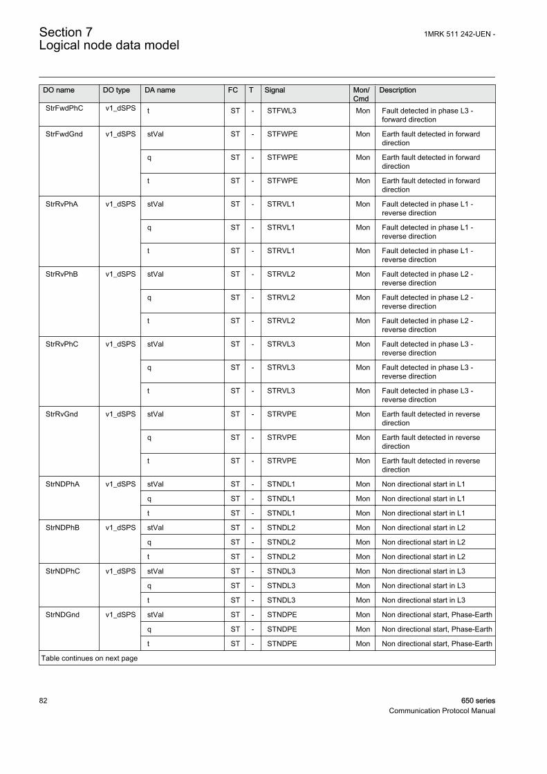
DO name DO type DA name FC T Signal Mon/Cmd
Description
StrFwdPhC v1_dSPS t ST - STFWL3 Mon Fault detected in phase L3 -forward direction
StrFwdGnd v1_dSPS stVal ST - STFWPE Mon Earth fault detected in forwarddirection
q ST - STFWPE Mon Earth fault detected in forwarddirection
t ST - STFWPE Mon Earth fault detected in forwarddirection
StrRvPhA v1_dSPS stVal ST - STRVL1 Mon Fault detected in phase L1 -reverse direction
q ST - STRVL1 Mon Fault detected in phase L1 -reverse direction
t ST - STRVL1 Mon Fault detected in phase L1 -reverse direction
StrRvPhB v1_dSPS stVal ST - STRVL2 Mon Fault detected in phase L2 -reverse direction
q ST - STRVL2 Mon Fault detected in phase L2 -reverse direction
t ST - STRVL2 Mon Fault detected in phase L2 -reverse direction
StrRvPhC v1_dSPS stVal ST - STRVL3 Mon Fault detected in phase L3 -reverse direction
q ST - STRVL3 Mon Fault detected in phase L3 -reverse direction
t ST - STRVL3 Mon Fault detected in phase L3 -reverse direction
StrRvGnd v1_dSPS stVal ST - STRVPE Mon Earth fault detected in reversedirection
q ST - STRVPE Mon Earth fault detected in reversedirection
t ST - STRVPE Mon Earth fault detected in reversedirection
StrNDPhA v1_dSPS stVal ST - STNDL1 Mon Non directional start in L1
q ST - STNDL1 Mon Non directional start in L1
t ST - STNDL1 Mon Non directional start in L1
StrNDPhB v1_dSPS stVal ST - STNDL2 Mon Non directional start in L2
q ST - STNDL2 Mon Non directional start in L2
t ST - STNDL2 Mon Non directional start in L2
StrNDPhC v1_dSPS stVal ST - STNDL3 Mon Non directional start in L3
q ST - STNDL3 Mon Non directional start in L3
t ST - STNDL3 Mon Non directional start in L3
StrNDGnd v1_dSPS stVal ST - STNDPE Mon Non directional start, Phase-Earth
q ST - STNDPE Mon Non directional start, Phase-Earth
t ST - STNDPE Mon Non directional start, Phase-Earth
Table continues on next page
Section 7 1MRK 511 242-UEN -Logical node data model
82 650 seriesCommunication Protocol Manual

DO name DO type DA name FC T Signal Mon/Cmd
Description
Str1Ph v1_dSPS stVal ST - STFW1PH Mon Start in forward direction for single-phase fault
q ST - STFW1PH Mon Start in forward direction for single-phase fault
t ST - STFW1PH Mon Start in forward direction for single-phase fault
Str2Ph v1_dSPS stVal ST - STFW2PH Mon Start in forward direction for two-phase fault
q ST - STFW2PH Mon Start in forward direction for two-phase fault
t ST - STFW2PH Mon Start in forward direction for two-phase fault
Str3Ph v1_dSPS stVal ST - STFW3PH Mon Start in forward direction for three-phase fault
q ST - STFW3PH Mon Start in forward direction for three-phase fault
t ST - STFW3PH Mon Start in forward direction for three-phase fault
RelGnd v1_dSPS stVal ST - STPE Mon Current conditions release ofPhase-Earth measuring elements
q ST - STPE Mon Current conditions release ofPhase-Earth measuring elements
t ST - STPE Mon Current conditions release ofPhase-Earth measuring elements
RelPP v1_dSPS stVal ST - STPP Mon Current conditions release ofPhase-Phase measuringelements
q ST - STPP Mon Current conditions release ofPhase-Phase measuringelements
t ST - STPP Mon Current conditions release ofPhase-Phase measuringelements
7.5.2.3 Five zone distance protection, mho characteristic ZMOPDIS
LN type LN prefix LN class Function block name
ZMOLLN0 instance 1 (revision 0) - LLN0 ZMOPDIS
ZMOPDIS instance 1 (revision 0) ZMO PDIS ZMOPDIS
ZMOPDIS instance 2 (revision 0) ZMO PDIS ZMOPDIS
ZMOPDIS instance 3 (revision 0) ZMO PDIS ZMOPDIS
ZMOPDIS instance 4 (revision 0) ZMO PDIS ZMOPDIS
ZMOPDIS instance 5 (revision 0) ZMO PDIS ZMOPDIS
ZMOPTRC instance 1 (revision 0) ZMO PTRC ZMOPDIS
1MRK 511 242-UEN - Section 7Logical node data model
650 series 83Communication Protocol Manual
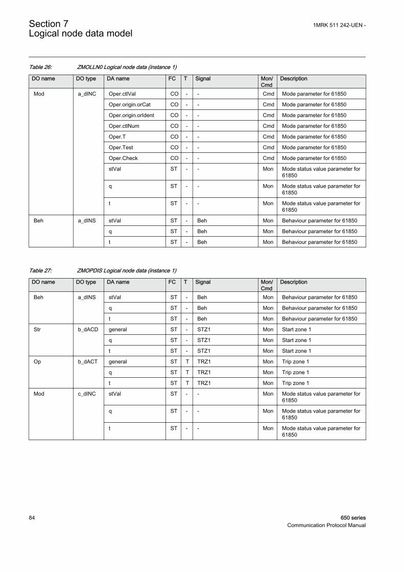
Table 26: ZMOLLN0 Logical node data (instance 1)
DO name DO type DA name FC T Signal Mon/Cmd
Description
Mod a_dINC Oper.ctlVal CO - - Cmd Mode parameter for 61850
Oper.origin.orCat CO - - Cmd Mode parameter for 61850
Oper.origin.orIdent CO - - Cmd Mode parameter for 61850
Oper.ctlNum CO - - Cmd Mode parameter for 61850
Oper.T CO - - Cmd Mode parameter for 61850
Oper.Test CO - - Cmd Mode parameter for 61850
Oper.Check CO - - Cmd Mode parameter for 61850
stVal ST - - Mon Mode status value parameter for61850
q ST - - Mon Mode status value parameter for61850
t ST - - Mon Mode status value parameter for61850
Beh a_dINS stVal ST - Beh Mon Behaviour parameter for 61850
q ST - Beh Mon Behaviour parameter for 61850
t ST - Beh Mon Behaviour parameter for 61850
Table 27: ZMOPDIS Logical node data (instance 1)
DO name DO type DA name FC T Signal Mon/Cmd
Description
Beh a_dINS stVal ST - Beh Mon Behaviour parameter for 61850
q ST - Beh Mon Behaviour parameter for 61850
t ST - Beh Mon Behaviour parameter for 61850
Str b_dACD general ST - STZ1 Mon Start zone 1
q ST - STZ1 Mon Start zone 1
t ST - STZ1 Mon Start zone 1
Op b_dACT general ST T TRZ1 Mon Trip zone 1
q ST T TRZ1 Mon Trip zone 1
t ST T TRZ1 Mon Trip zone 1
Mod c_dINC stVal ST - - Mon Mode status value parameter for61850
q ST - - Mon Mode status value parameter for61850
t ST - - Mon Mode status value parameter for61850
Section 7 1MRK 511 242-UEN -Logical node data model
84 650 seriesCommunication Protocol Manual

Table 28: ZMOPDIS Logical node data (instance 2)
DO name DO type DA name FC T Signal Mon/Cmd
Description
Beh a_dINS stVal ST - Beh Mon Behaviour parameter for 61850
q ST - Beh Mon Behaviour parameter for 61850
t ST - Beh Mon Behaviour parameter for 61850
Str b_dACD general ST - STZ2 Mon Start zone 2
q ST - STZ2 Mon Start zone 2
t ST - STZ2 Mon Start zone 2
Op b_dACT general ST T TRZ2 Mon Trip zone 2
q ST T TRZ2 Mon Trip zone 2
t ST T TRZ2 Mon Trip zone 2
Mod c_dINC stVal ST - - Mon Mode status value parameter for61850
q ST - - Mon Mode status value parameter for61850
t ST - - Mon Mode status value parameter for61850
Table 29: ZMOPDIS Logical node data (instance 3)
DO name DO type DA name FC T Signal Mon/Cmd
Description
Beh a_dINS stVal ST - Beh Mon Behaviour parameter for 61850
q ST - Beh Mon Behaviour parameter for 61850
t ST - Beh Mon Behaviour parameter for 61850
Str b_dACD general ST - STZ3 Mon Start zone 3
q ST - STZ3 Mon Start zone 3
t ST - STZ3 Mon Start zone 3
Op b_dACT general ST T TRZ3 Mon Trip zone 3
q ST T TRZ3 Mon Trip zone 3
t ST T TRZ3 Mon Trip zone 3
Mod c_dINC stVal ST - - Mon Mode status value parameter for61850
q ST - - Mon Mode status value parameter for61850
t ST - - Mon Mode status value parameter for61850
1MRK 511 242-UEN - Section 7Logical node data model
650 series 85Communication Protocol Manual

Table 30: ZMOPDIS Logical node data (instance 4)
DO name DO type DA name FC T Signal Mon/Cmd
Description
Beh a_dINS stVal ST - Beh Mon Behaviour parameter for 61850
q ST - Beh Mon Behaviour parameter for 61850
t ST - Beh Mon Behaviour parameter for 61850
Str b_dACD general ST - STZ4 Mon Start zone 4
q ST - STZ4 Mon Start zone 4
t ST - STZ4 Mon Start zone 4
Op b_dACT general ST T TRZ4 Mon Trip zone 4
q ST T TRZ4 Mon Trip zone 4
t ST T TRZ4 Mon Trip zone 4
Mod c_dINC stVal ST - - Mon Mode status value parameter for61850
q ST - - Mon Mode status value parameter for61850
t ST - - Mon Mode status value parameter for61850
Table 31: ZMOPDIS Logical node data (instance 5)
DO name DO type DA name FC T Signal Mon/Cmd
Description
Beh a_dINS stVal ST - Beh Mon Behaviour parameter for 61850
q ST - Beh Mon Behaviour parameter for 61850
t ST - Beh Mon Behaviour parameter for 61850
Str b_dACD general ST - STZ5 Mon Start zone 5
q ST - STZ5 Mon Start zone 5
t ST - STZ5 Mon Start zone 5
Op b_dACT general ST T TRZ5 Mon Trip zone 5
q ST T TRZ5 Mon Trip zone 5
t ST T TRZ5 Mon Trip zone 5
Mod c_dINC stVal ST - - Mon Mode status value parameter for61850
q ST - - Mon Mode status value parameter for61850
t ST - - Mon Mode status value parameter for61850
Section 7 1MRK 511 242-UEN -Logical node data model
86 650 seriesCommunication Protocol Manual

Table 32: ZMOPTRC Logical node data (instance 1)
DO name DO type DA name FC T Signal Mon/Cmd
Description
Beh a_dINS stVal ST - Beh Mon Behaviour parameter for 61850
q ST - Beh Mon Behaviour parameter for 61850
t ST - Beh Mon Behaviour parameter for 61850
Str b_dACD general ST - START Mon Start general
q ST - START Mon Start general
t ST - START Mon Start general
Op b_dACT general ST T TRIP Mon Trip general
q ST T TRIP Mon Trip general
t ST T TRIP Mon Trip general
Mod c_dINC stVal ST - - Mon Mode status value parameter for61850
q ST - - Mon Mode status value parameter for61850
t ST - - Mon Mode status value parameter for61850
7.5.2.4 Faulty phase identification with load enchroachment for mhoFMPSPDIS
LN type LN prefix LN class Function block name
FMPSPDIS (revision 1) FMPS PDIS FMPSPDIS
Table 33: FMPSPDIS Logical node data (instance 1)
DO name DO type DA name FC T Signal Mon/Cmd
Description
Op a_dACT general ST T START Mon General start signal
phsA ST T STL1 Mon Fault detected in phase L1
phsB ST T STL2 Mon Fault detected in phase L2
phsC ST T STL3 Mon Fault detected in phase L3
q ST T START Mon General start signal
t ST T START Mon General start signal
Mod a_dINC Oper.ctlVal CO - - Cmd Mode parameter
Oper.origin.orCat CO - - Cmd Mode parameter
Oper.origin.orIdent CO - - Cmd Mode parameter
Oper.ctlNum CO - - Cmd Mode parameter
Oper.T CO - - Cmd Mode parameter
Oper.Test CO - - Cmd Mode parameter
Oper.Check CO - - Cmd Mode parameter
Table continues on next page
1MRK 511 242-UEN - Section 7Logical node data model
650 series 87Communication Protocol Manual

DO name DO type DA name FC T Signal Mon/Cmd
Description
Mod a_dINC stVal ST - - Mon Mode status parameter for 61850
q ST - - Mon Mode status parameter for 61850
t ST - - Mon Mode status parameter for 61850
Beh a_dINS stVal ST - Beh Mon Behaviour parameter for 61850
q ST - Beh Mon Behaviour parameter for 61850
t ST - Beh Mon Behaviour parameter for 61850
Str e_dACD general ST - START Mon General start signal
phsA ST - STL1 Mon Fault detected in phase L1
phsB ST - STL2 Mon Fault detected in phase L2
phsC ST - STL3 Mon Fault detected in phase L3
neut ST - STPE Mon Earth fault detected
q ST - START Mon General start signal
t ST - START Mon General start signal
7.5.2.5 Underimpedance protection for generator and transformer ZGPDIS
LN type LN prefix LN class Function block name
ZGLLN0 instance 1 (revision 0) - LLN0 ZGPDIS
ZGPDIS instance 1 (revision 0) ZG PDIS ZGPDIS
ZGPDIS instance 2 (revision 0) ZG PDIS ZGPDIS
ZGPDIS instance 3 (revision 0) ZG PDIS ZGPDIS
ZGPDIS instance 4 (revision 0) ZG PDIS ZGPDIS
ZGPDIS instance 5 (revision 0) ZG PDIS ZGPDIS
ZGPTRC instance 1 (revision 0) ZG PTRC ZGPDIS
Table 34: ZGLLN0 Logical node data (instance 1)
DO name DO type DA name FC T Signal Mon/Cmd
Description
Mod a_dINC Oper.ctlVal CO - - Cmd Mode parameter for 61850
Oper.origin.orCat CO - - Cmd Mode parameter for 61850
Oper.origin.orIdent CO - - Cmd Mode parameter for 61850
Oper.ctlNum CO - - Cmd Mode parameter for 61850
Oper.T CO - - Cmd Mode parameter for 61850
Oper.Test CO - - Cmd Mode parameter for 61850
Oper.Check CO - - Cmd Mode parameter for 61850
stVal ST - - Mon Mode status value parameter for61850
q ST - - Mon Mode status value parameter for61850
Table continues on next page
Section 7 1MRK 511 242-UEN -Logical node data model
88 650 seriesCommunication Protocol Manual

DO name DO type DA name FC T Signal Mon/Cmd
Description
Mod a_dINC t ST - - Mon Mode status value parameter for61850
Beh a_dINS stVal ST - Beh Mon Behaviour parameter for 61850
q ST - Beh Mon Behaviour parameter for 61850
t ST - Beh Mon Behaviour parameter for 61850
Table 35: ZGPDIS Logical node data (instance 1)
DO name DO type DA name FC T Signal Mon/Cmd
Description
Beh a_dINS stVal ST - Beh Mon Behaviour parameter for 61850
q ST - Beh Mon Behaviour parameter for 61850
t ST - Beh Mon Behaviour parameter for 61850
Str b_dACD general ST - STZ1 Mon Start zone 1
q ST - STZ1 Mon Start zone 1
t ST - STZ1 Mon Start zone 1
Op b_dACT general ST T TRZ1 Mon Trip zone 1
q ST T TRZ1 Mon Trip zone 1
t ST T TRZ1 Mon Trip zone 1
Mod c_dINC stVal ST - - Mon Mode status value parameter for61850
q ST - - Mon Mode status value parameter for61850
t ST - - Mon Mode status value parameter for61850
Table 36: ZGPDIS Logical node data (instance 2)
DO name DO type DA name FC T Signal Mon/Cmd
Description
Beh a_dINS stVal ST - Beh Mon Behaviour parameter for 61850
q ST - Beh Mon Behaviour parameter for 61850
t ST - Beh Mon Behaviour parameter for 61850
Str b_dACD general ST - STZ2 Mon Start zone 2
q ST - STZ2 Mon Start zone 2
t ST - STZ2 Mon Start zone 2
Op b_dACT general ST T TRZ2 Mon Trip zone 2
q ST T TRZ2 Mon Trip zone 2
t ST T TRZ2 Mon Trip zone 2
Table continues on next page
1MRK 511 242-UEN - Section 7Logical node data model
650 series 89Communication Protocol Manual

DO name DO type DA name FC T Signal Mon/Cmd
Description
Mod c_dINC stVal ST - - Mon Mode status value parameter for61850
q ST - - Mon Mode status value parameter for61850
t ST - - Mon Mode status value parameter for61850
Table 37: ZGPDIS Logical node data (instance 3)
DO name DO type DA name FC T Signal Mon/Cmd
Description
Beh a_dINS stVal ST - Beh Mon Behaviour parameter for 61850
q ST - Beh Mon Behaviour parameter for 61850
t ST - Beh Mon Behaviour parameter for 61850
Str b_dACD general ST - STZ3 Mon Start zone 3
q ST - STZ3 Mon Start zone 3
t ST - STZ3 Mon Start zone 3
Op b_dACT general ST T TRZ3 Mon Trip zone 3
q ST T TRZ3 Mon Trip zone 3
t ST T TRZ3 Mon Trip zone 3
Mod c_dINC stVal ST - - Mon Mode status value parameter for61850
q ST - - Mon Mode status value parameter for61850
t ST - - Mon Mode status value parameter for61850
Table 38: ZGPTRC Logical node data (instance 1)
DO name DO type DA name FC T Signal Mon/Cmd
Description
Beh a_dINS stVal ST - Beh Mon Behaviour parameter for 61850
q ST - Beh Mon Behaviour parameter for 61850
t ST - Beh Mon Behaviour parameter for 61850
Str b_dACD general ST - START Mon Start general
q ST - START Mon Start general
t ST - START Mon Start general
Op b_dACT general ST - TRIP Mon Trip general
q ST - TRIP Mon Trip general
t ST - TRIP Mon Trip general
Table continues on next page
Section 7 1MRK 511 242-UEN -Logical node data model
90 650 seriesCommunication Protocol Manual

DO name DO type DA name FC T Signal Mon/Cmd
Description
Mod c_dINC stVal ST - - Mon Mode status value parameter for61850
q ST - - Mon Mode status value parameter for61850
t ST - - Mon Mode status value parameter for61850
7.5.2.6 Loss of exectation LEXPDIS
LN type LN prefix LN class Function block name
LEXPDIS (revision 1) LEX PDIS LEXPDIS
Table 39: LEXPDIS Logical node data (instance 1)
DO name DO type DA name FC T Signal Mon/Cmd
Description
Mod a_dINC Oper.ctlVal CO - - Cmd Mode parameter
Oper.origin.orCat CO - - Cmd Mode parameter
Oper.origin.orIdent CO - - Cmd Mode parameter
Oper.ctlNum CO - - Cmd Mode parameter
Oper.T CO - - Cmd Mode parameter
Oper.Test CO - - Cmd Mode parameter
Oper.Check CO - - Cmd Mode parameter
stVal ST - - Mon Mode status parameter for 61850
q ST - - Mon Mode status parameter for 61850
t ST - - Mon Mode status parameter for 61850
Beh a_dINS stVal ST - Beh Mon Behaviour parameter for 61850
q ST - Beh Mon Behaviour parameter for 61850
t ST - Beh Mon Behaviour parameter for 61850
Str b_dACD general ST - START Mon Common start signal
q ST - START Mon Common start signal
t ST - START Mon Common start signal
Op b_dACT general ST T TRIP Mon Common trip signal
q ST T TRIP Mon Common trip signal
t ST T TRIP Mon Common trip signal
OpZ1 v1_dSPS stVal ST - TRZ1 Mon Trip signal from impedance zoneZ1
q ST - TRZ1 Mon Trip signal from impedance zoneZ1
t ST - TRZ1 Mon Trip signal from impedance zoneZ1
Table continues on next page
1MRK 511 242-UEN - Section 7Logical node data model
650 series 91Communication Protocol Manual

DO name DO type DA name FC T Signal Mon/Cmd
Description
OpZ2 v1_dSPS stVal ST - TRZ2 Mon Trip signal from impedance zoneZ2
q ST - TRZ2 Mon Trip signal from impedance zoneZ2
t ST - TRZ2 Mon Trip signal from impedance zoneZ2
StrZ1 v1_dSPS stVal ST - STZ1 Mon Start signal from impedance zoneZ1
q ST - STZ1 Mon Start signal from impedance zoneZ1
t ST - STZ1 Mon Start signal from impedance zoneZ1
StrZ2 v1_dSPS stVal ST - STZ2 Mon Start signal from impedance zoneZ2
q ST - STZ2 Mon Start signal from impedance zoneZ2
t ST - STZ2 Mon Start signal from impedance zoneZ2
PriRis v2_dMV mag.f MX - ROHM Mon Resistance in Primary Ohms
q MX - ROHM Mon Resistance in Primary Ohms
t MX - ROHM Mon Resistance in Primary Ohms
PriReact v2_dMV mag.f MX - XOHM Mon Reactance in Primary Ohms
q MX - XOHM Mon Reactance in Primary Ohms
t MX - XOHM Mon Reactance in Primary Ohms
7.5.2.7 Faulty phase identification with load enchroachment for mho LEPDIS
LN type LN prefix LN class Function block name
LEPDIS (revision 0) LE PDIS LEPDIS
Table 40: LEPDIS Logical node data (instance 1)
DO name DO type DA name FC T Signal Mon/Cmd
Description
Op a_dACT general ST T - Mon General start signal
phsA ST T - Mon Fault detected in phase L1
phsB ST T - Mon Fault detected in phase L2
phsC ST T - Mon Fault detected in phase L3
q ST T - Mon General start signal
t ST T - Mon General start signal
Mod a_dINC Oper.ctlVal CO - - Cmd Mode parameter
Oper.origin.orCat CO - - Cmd Mode parameter
Oper.origin.orIdent CO - - Cmd Mode parameter
Table continues on next page
Section 7 1MRK 511 242-UEN -Logical node data model
92 650 seriesCommunication Protocol Manual

DO name DO type DA name FC T Signal Mon/Cmd
Description
Mod a_dINC Oper.ctlNum CO - - Cmd Mode parameter
Oper.T CO - - Cmd Mode parameter
Oper.Test CO - - Cmd Mode parameter
Oper.Check CO - - Cmd Mode parameter
stVal ST - - Mon Mode status parameter for 61850
q ST - - Mon Mode status parameter for 61850
t ST - - Mon Mode status parameter for 61850
Beh a_dINS stVal ST - Beh Mon Behaviour parameter for 61850
q ST - Beh Mon Behaviour parameter for 61850
t ST - Beh Mon Behaviour parameter for 61850
Str e_dACD general ST - - Mon General start signal
phsA ST - - Mon Fault detected in phase L1
phsB ST - - Mon Fault detected in phase L2
phsC ST - - Mon Fault detected in phase L3
neut ST - - Mon Earth fault detected
q ST - - Mon General start signal
t ST - - Mon General start signal
7.5.3 Directional overpower PDOP
7.5.3.1 Directional Over-power protection GOPPDOP
LN type LN prefix LN class Function block name
GOPPDOP (revision 1) GOP PDOP GOPPDOP
Table 41: GOPPDOP Logical node data (instance 1)
DO name DO type DA name FC T Signal Mon/Cmd
Description
Mod a_dINC Oper.ctlVal CO - - Cmd Mode parameter for 61850
Oper.origin.orCat CO - - Cmd Mode parameter for 61850
Oper.origin.orIdent CO - - Cmd Mode parameter for 61850
Oper.ctlNum CO - - Cmd Mode parameter for 61850
Oper.T CO - - Cmd Mode parameter for 61850
Oper.Test CO - - Cmd Mode parameter for 61850
Oper.Check CO - - Cmd Mode parameter for 61850
stVal ST - - Mon Mode status value parameter for61850
q ST - - Mon Mode status value parameter for61850
Table continues on next page
1MRK 511 242-UEN - Section 7Logical node data model
650 series 93Communication Protocol Manual
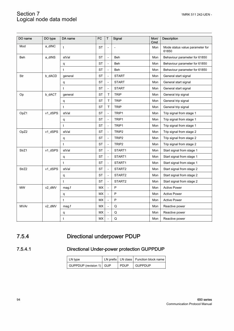
DO name DO type DA name FC T Signal Mon/Cmd
Description
Mod a_dINC t ST - - Mon Mode status value parameter for61850
Beh a_dINS stVal ST - Beh Mon Behaviour parameter for 61850
q ST - Beh Mon Behaviour parameter for 61850
t ST - Beh Mon Behaviour parameter for 61850
Str b_dACD general ST - START Mon General start signal
q ST - START Mon General start signal
t ST - START Mon General start signal
Op b_dACT general ST T TRIP Mon General trip signal
q ST T TRIP Mon General trip signal
t ST T TRIP Mon General trip signal
OpZ1 v1_dSPS stVal ST - TRIP1 Mon Trip signal from stage 1
q ST - TRIP1 Mon Trip signal from stage 1
t ST - TRIP1 Mon Trip signal from stage 1
OpZ2 v1_dSPS stVal ST - TRIP2 Mon Trip signal from stage 2
q ST - TRIP2 Mon Trip signal from stage 2
t ST - TRIP2 Mon Trip signal from stage 2
StrZ1 v1_dSPS stVal ST - START1 Mon Start signal from stage 1
q ST - START1 Mon Start signal from stage 1
t ST - START1 Mon Start signal from stage 1
StrZ2 v1_dSPS stVal ST - START2 Mon Start signal from stage 2
q ST - START2 Mon Start signal from stage 2
t ST - START2 Mon Start signal from stage 2
MW v2_dMV mag.f MX - P Mon Active Power
q MX - P Mon Active Power
t MX - P Mon Active Power
MVAr v2_dMV mag.f MX - Q Mon Reactive power
q MX - Q Mon Reactive power
t MX - Q Mon Reactive power
7.5.4 Directional underpower PDUP
7.5.4.1 Directional Under-power protection GUPPDUP
LN type LN prefix LN class Function block name
GUPPDUP (revision 1) GUP PDUP GUPPDUP
Section 7 1MRK 511 242-UEN -Logical node data model
94 650 seriesCommunication Protocol Manual
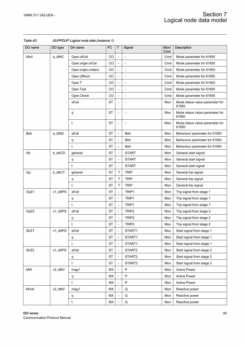
Table 42: GUPPDUP Logical node data (instance 1)
DO name DO type DA name FC T Signal Mon/Cmd
Description
Mod a_dINC Oper.ctlVal CO - - Cmd Mode parameter for 61850
Oper.origin.orCat CO - - Cmd Mode parameter for 61850
Oper.origin.orIdent CO - - Cmd Mode parameter for 61850
Oper.ctlNum CO - - Cmd Mode parameter for 61850
Oper.T CO - - Cmd Mode parameter for 61850
Oper.Test CO - - Cmd Mode parameter for 61850
Oper.Check CO - - Cmd Mode parameter for 61850
stVal ST - - Mon Mode status value parameter for61850
q ST - - Mon Mode status value parameter for61850
t ST - - Mon Mode status value parameter for61850
Beh a_dINS stVal ST - Beh Mon Behaviour parameter for 61850
q ST - Beh Mon Behaviour parameter for 61850
t ST - Beh Mon Behaviour parameter for 61850
Str b_dACD general ST - START Mon General start signal
q ST - START Mon General start signal
t ST - START Mon General start signal
Op b_dACT general ST T TRIP Mon General trip signal
q ST T TRIP Mon General trip signal
t ST T TRIP Mon General trip signal
OpZ1 v1_dSPS stVal ST - TRIP1 Mon Trip signal from stage 1
q ST - TRIP1 Mon Trip signal from stage 1
t ST - TRIP1 Mon Trip signal from stage 1
OpZ2 v1_dSPS stVal ST - TRIP2 Mon Trip signal from stage 2
q ST - TRIP2 Mon Trip signal from stage 2
t ST - TRIP2 Mon Trip signal from stage 2
StrZ1 v1_dSPS stVal ST - START1 Mon Start signal from stage 1
q ST - START1 Mon Start signal from stage 1
t ST - START1 Mon Start signal from stage 1
StrZ2 v1_dSPS stVal ST - START2 Mon Start signal from stage 2
q ST - START2 Mon Start signal from stage 2
t ST - START2 Mon Start signal from stage 2
MW v2_dMV mag.f MX - P Mon Active Power
q MX - P Mon Active Power
t MX - P Mon Active Power
MVAr v2_dMV mag.f MX - Q Mon Reactive power
q MX - Q Mon Reactive power
t MX - Q Mon Reactive power
1MRK 511 242-UEN - Section 7Logical node data model
650 series 95Communication Protocol Manual

7.5.5 Rate of change of frequency PFRC
7.5.5.1 Rate-of-change frequency function SAPFRC
LN type LN prefix LN class Function block name
SAPFRC (revision 1) SA PFRC SAPFRC
Table 43: SAPFRC Logical node data (instance 0)
DO name DO type DA name FC T Signal Mon/Cmd
Description
Mod a_dINC Oper.ctlVal CO - - Cmd Mode parameter
Oper.origin.orCat CO - - Cmd Mode parameter
Oper.origin.orIdent CO - - Cmd Mode parameter
Oper.ctlNum CO - - Cmd Mode parameter
Oper.T CO - - Cmd Mode parameter
Oper.Test CO - - Cmd Mode parameter
Oper.Check CO - - Cmd Mode parameter
stVal ST - - Mon Mode status parameter for 61850
q ST - - Mon Mode status parameter for 61850
t ST - - Mon Mode status parameter for 61850
Beh a_dINS stVal ST - Beh Mon Behaviour parameter for 61850
q ST - Beh Mon Behaviour parameter for 61850
t ST - Beh Mon Behaviour parameter for 61850
Str b_dACD general ST - START Mon Start/pick-up signal for frequencygradient
q ST - START Mon Start/pick-up signal for frequencygradient
t ST - START Mon Start/pick-up signal for frequencygradient
Op b_dACT general ST T TRIP Mon Operate/trip signal for frequencygradient
q ST T TRIP Mon Operate/trip signal for frequencygradient
t ST T TRIP Mon Operate/trip signal for frequencygradient
BlkLoMg v1_dSPS stVal ST - BLKDMAGN Mon Blocking indication due to lowamplitude
q ST - BLKDMAGN Mon Blocking indication due to lowamplitude
t ST - BLKDMAGN Mon Blocking indication due to lowamplitude
Table continues on next page
Section 7 1MRK 511 242-UEN -Logical node data model
96 650 seriesCommunication Protocol Manual

DO name DO type DA name FC T Signal Mon/Cmd
Description
RestLd v1_dSPS stVal ST - RESTORE Mon Restore signal for load restoringpurposes
q ST - RESTORE Mon Restore signal for load restoringpurposes
t ST - RESTORE Mon Restore signal for load restoringpurposes
7.5.6 Instantaneous overcurrent PIOC
7.5.6.1 Instantaneous phase overcurrent protection PHPIOC
LN type LN prefix LN class Function block name
PHPIOC (revision 1) PH PIOC PHPIOC
Table 44: PHPIOC Logical node data (instance 0)
DO name DO type DA name FC T Signal Mon/Cmd
Description
Mod a_dINC Oper.ctlVal CO - - Cmd Mode parameter for 61850
Oper.origin.orCat CO - - Cmd Mode parameter for 61850
Oper.origin.orIdent CO - - Cmd Mode parameter for 61850
Oper.ctlNum CO - - Cmd Mode parameter for 61850
Oper.T CO - - Cmd Mode parameter for 61850
Oper.Test CO - - Cmd Mode parameter for 61850
Oper.Check CO - - Cmd Mode parameter for 61850
stVal ST - - Mon Mode status parameter for 61850
q ST - - Mon Mode status parameter for 61850
t ST - - Mon Mode status parameter for 61850
Beh a_dINS stVal ST - Beh Mon Behaviour parameter for 61850
q ST - Beh Mon Behaviour parameter for 61850
t ST - Beh Mon Behaviour parameter for 61850
Op b_dACT general ST T TRIP Mon General trip signal
q ST T TRIP Mon General trip signal
t ST T TRIP Mon General trip signal
7.5.6.2 Instantaneous residual overcurrent protection EFPIOC
LN type LN prefix LN class Function block name
EFPIOC (revision 1) EF PIOC EFPIOC
1MRK 511 242-UEN - Section 7Logical node data model
650 series 97Communication Protocol Manual

Table 45: EFPIOC Logical node data (instance 0)
DO name DO type DA name FC T Signal Mon/Cmd
Description
Mod a_dINC Oper.ctlVal CO - - Cmd Mode parameter
Oper.origin.orCat CO - - Cmd Mode parameter
Oper.origin.orIdent CO - - Cmd Mode parameter
Oper.ctlNum CO - - Cmd Mode parameter
Oper.T CO - - Cmd Mode parameter
Oper.Test CO - - Cmd Mode parameter
Oper.Check CO - - Cmd Mode parameter
stVal ST - - Mon Mode status parameter for 61850
q ST - - Mon Mode status parameter for 61850
t ST - - Mon Mode status parameter for 61850
Beh a_dINS stVal ST - Beh Mon Behaviour parameter for 61850
q ST - Beh Mon Behaviour parameter for 61850
t ST - Beh Mon Behaviour parameter for 61850
Op b_dACT general ST T TRIP Mon Trip signal
q ST T TRIP Mon Trip signal
t ST T TRIP Mon Trip signal
7.5.7 Local acceleration logic PLAL
7.5.7.1 Local acceleration logic ZCLCPLAL
LN type LN prefix LN class Function block name
ZCLCPLAL (revision 1) ZCLC PLAL ZCLCPLAL
Table 46: ZCLCPLAL Logical node data (instance 0)
DO name DO type DA name FC T Signal Mon/Cmd
Description
Mod a_dINC Oper.ctlVal CO - - Cmd Mode parameter
Oper.origin.orCat CO - - Cmd Mode parameter
Oper.origin.orIdent CO - - Cmd Mode parameter
Oper.ctlNum CO - - Cmd Mode parameter
Oper.T CO - - Cmd Mode parameter
Oper.Test CO - - Cmd Mode parameter
Oper.Check CO - - Cmd Mode parameter
stVal ST - - Mon Mode status parameter for 61850
q ST - - Mon Mode status parameter for 61850
t ST - - Mon Mode status parameter for 61850
Table continues on next page
Section 7 1MRK 511 242-UEN -Logical node data model
98 650 seriesCommunication Protocol Manual

DO name DO type DA name FC T Signal Mon/Cmd
Description
Beh a_dINS stVal ST - Beh Mon Behaviour parameter for 61850
q ST - Beh Mon Behaviour parameter for 61850
t ST - Beh Mon Behaviour parameter for 61850
OpLosLod v2_dACT general ST - TRLL Mon Trip by loss of load
q ST - TRLL Mon Trip by loss of load
t ST - TRLL Mon Trip by loss of load
OpZnExd v2_dACT general ST - TRZE Mon Trip by zone extension
q ST - TRZE Mon Trip by zone extension
t ST - TRZE Mon Trip by zone extension
7.5.8 Protection scheme PSCH
7.5.8.1 Scheme communication logic for distance or overcurrent protectionZCPSCH
LN type LN prefix LN class Function block name
ZCPSCH (revision 1) ZC PSCH ZCPSCH
Table 47: ZCPSCH Logical node data (instance 0)
DO name DO type DA name FC T Signal Mon/Cmd
Description
Mod a_dINC Oper.ctlVal CO - - Cmd Mode parameter
Oper.origin.orCat CO - - Cmd Mode parameter
Oper.origin.orIdent CO - - Cmd Mode parameter
Oper.ctlNum CO - - Cmd Mode parameter
Oper.T CO - - Cmd Mode parameter
Oper.Test CO - - Cmd Mode parameter
Oper.Check CO - - Cmd Mode parameter
stVal ST - - Mon Mode status parameter for 61850
q ST - - Mon Mode status parameter for 61850
t ST - - Mon Mode status parameter for 61850
Beh a_dINS stVal ST - Beh Mon Behaviour parameter for 61850
q ST - Beh Mon Behaviour parameter for 61850
t ST - Beh Mon Behaviour parameter for 61850
LosOfGrd a_dSPS stVal ST - LCG Mon Loss of carrier guard signal
q ST - LCG Mon Loss of carrier guard signal
t ST - LCG Mon Loss of carrier guard signal
ProRx a_dSPS stVal ST T - Mon Carrier signal received or missingcarrier guard signal
Table continues on next page
1MRK 511 242-UEN - Section 7Logical node data model
650 series 99Communication Protocol Manual
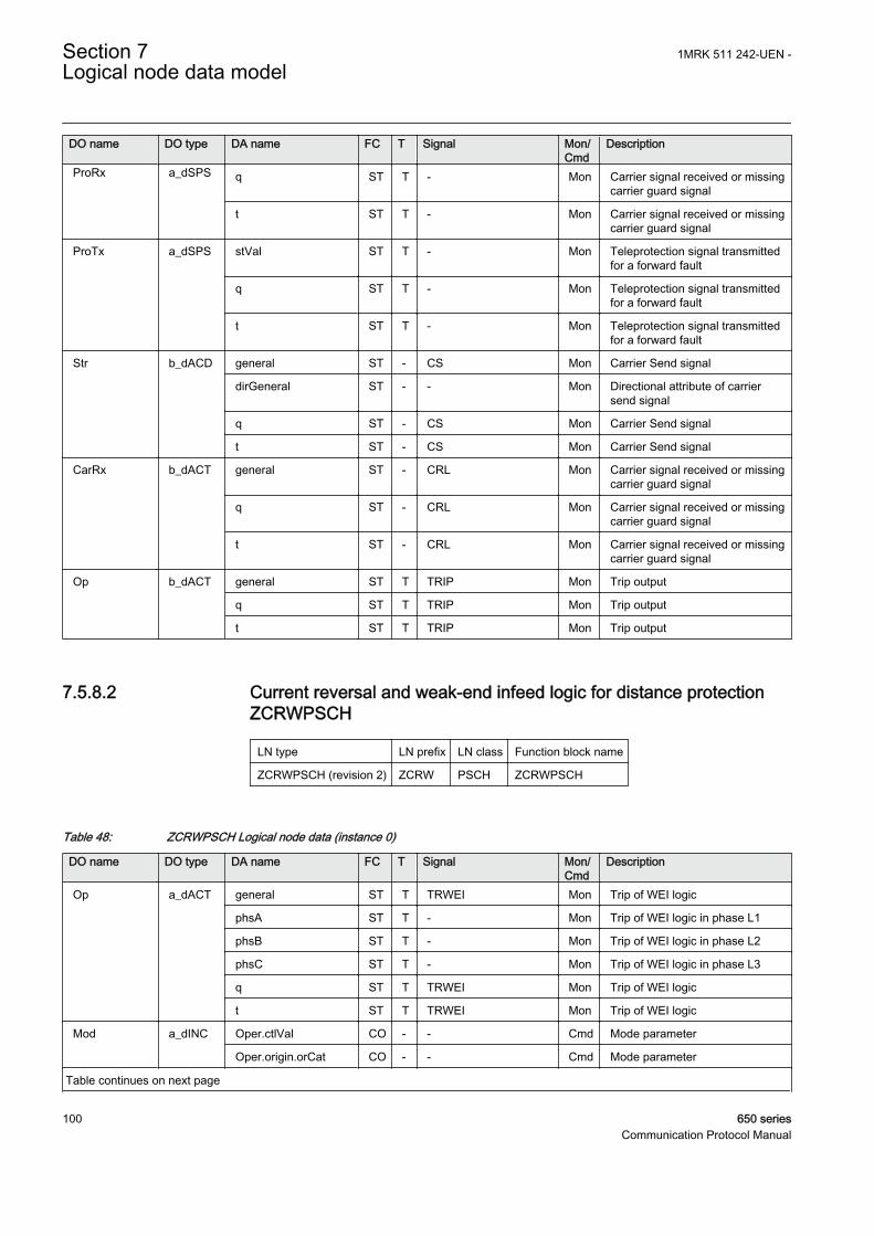
DO name DO type DA name FC T Signal Mon/Cmd
Description
ProRx a_dSPS q ST T - Mon Carrier signal received or missingcarrier guard signal
t ST T - Mon Carrier signal received or missingcarrier guard signal
ProTx a_dSPS stVal ST T - Mon Teleprotection signal transmittedfor a forward fault
q ST T - Mon Teleprotection signal transmittedfor a forward fault
t ST T - Mon Teleprotection signal transmittedfor a forward fault
Str b_dACD general ST - CS Mon Carrier Send signal
dirGeneral ST - - Mon Directional attribute of carriersend signal
q ST - CS Mon Carrier Send signal
t ST - CS Mon Carrier Send signal
CarRx b_dACT general ST - CRL Mon Carrier signal received or missingcarrier guard signal
q ST - CRL Mon Carrier signal received or missingcarrier guard signal
t ST - CRL Mon Carrier signal received or missingcarrier guard signal
Op b_dACT general ST T TRIP Mon Trip output
q ST T TRIP Mon Trip output
t ST T TRIP Mon Trip output
7.5.8.2 Current reversal and weak-end infeed logic for distance protectionZCRWPSCH
LN type LN prefix LN class Function block name
ZCRWPSCH (revision 2) ZCRW PSCH ZCRWPSCH
Table 48: ZCRWPSCH Logical node data (instance 0)
DO name DO type DA name FC T Signal Mon/Cmd
Description
Op a_dACT general ST T TRWEI Mon Trip of WEI logic
phsA ST T - Mon Trip of WEI logic in phase L1
phsB ST T - Mon Trip of WEI logic in phase L2
phsC ST T - Mon Trip of WEI logic in phase L3
q ST T TRWEI Mon Trip of WEI logic
t ST T TRWEI Mon Trip of WEI logic
Mod a_dINC Oper.ctlVal CO - - Cmd Mode parameter
Oper.origin.orCat CO - - Cmd Mode parameter
Table continues on next page
Section 7 1MRK 511 242-UEN -Logical node data model
100 650 seriesCommunication Protocol Manual

DO name DO type DA name FC T Signal Mon/Cmd
Description
Mod a_dINC Oper.origin.orIdent CO - - Cmd Mode parameter
Oper.ctlNum CO - - Cmd Mode parameter
Oper.T CO - - Cmd Mode parameter
Oper.Test CO - - Cmd Mode parameter
Oper.Check CO - - Cmd Mode parameter
stVal ST - - Mon Mode status parameter for 61850
q ST - - Mon Mode status parameter for 61850
t ST - - Mon Mode status parameter for 61850
Beh a_dINS stVal ST - Beh Mon Behaviour parameter for 61850
q ST - Beh Mon Behaviour parameter for 61850
t ST - Beh Mon Behaviour parameter for 61850
ProRx a_dSPS stVal ST T - Mon POR Carrier signal received fromremote end
q ST T - Mon POR Carrier signal received fromremote end
t ST T - Mon POR Carrier signal received fromremote end
ProTx a_dSPS stVal ST T ECHO Mon Carrier send by WEI logic
q ST T ECHO Mon Carrier send by WEI logic
t ST T ECHO Mon Carrier send by WEI logic
Str b_dACD general ST - ECHO Mon Carrier send by WEI logic
q ST - ECHO Mon Carrier send by WEI logic
t ST - ECHO Mon Carrier send by WEI logic
Echo b_dACT general ST - ECHO Mon Carrier send by WEI logic
q ST - ECHO Mon Carrier send by WEI logic
t ST - ECHO Mon Carrier send by WEI logic
RvABlk b_dACT general ST - IRVL Mon Operation of current reversal logic
q ST - IRVL Mon Operation of current reversal logic
t ST - IRVL Mon Operation of current reversal logic
WeiOp b_dACT general ST - TRWEI Mon Trip of WEI logic
q ST - TRWEI Mon Trip of WEI logic
t ST - TRWEI Mon Trip of WEI logic
7.5.8.3 Scheme communication logic for residual overcurrent protectionECPSCH
LN type LN prefix LN class Function block name
ECPSCH (revision 1) EC PSCH ECPSCH
1MRK 511 242-UEN - Section 7Logical node data model
650 series 101Communication Protocol Manual
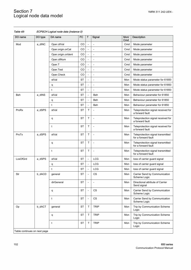
Table 49: ECPSCH Logical node data (instance 0)
DO name DO type DA name FC T Signal Mon/Cmd
Description
Mod a_dINC Oper.ctlVal CO - - Cmd Mode parameter
Oper.origin.orCat CO - - Cmd Mode parameter
Oper.origin.orIdent CO - - Cmd Mode parameter
Oper.ctlNum CO - - Cmd Mode parameter
Oper.T CO - - Cmd Mode parameter
Oper.Test CO - - Cmd Mode parameter
Oper.Check CO - - Cmd Mode parameter
stVal ST - - Mon Mode status parameter for 61850
q ST - - Mon Mode status parameter for 61850
t ST - - Mon Mode status parameter for 61850
Beh a_dINS stVal ST - Beh Mon Behaviour parameter for 61850
q ST - Beh Mon Behaviour parameter for 61850
t ST - Beh Mon Behaviour parameter for 61850
ProRx a_dSPS stVal ST T - Mon Teleprotection signal received fora forward fault
q ST T - Mon Teleprotection signal received fora forward fault
t ST T - Mon Teleprotection signal received fora forward fault
ProTx a_dSPS stVal ST T - Mon Teleprotection signal transmittedfor a forward fault
q ST T - Mon Teleprotection signal transmittedfor a forward fault
t ST T - Mon Teleprotection signal transmittedfor a forward fault
LosOfGrd a_dSPS stVal ST - LCG Mon loss of carrier guard signal
q ST - LCG Mon loss of carrier guard signal
t ST - LCG Mon loss of carrier guard signal
Str b_dACD general ST - CS Mon Carrier Send by CommunicationScheme Logic
dirGeneral ST - - Mon Directional attribute of CarrierSend signal
q ST - CS Mon Carrier Send by CommunicationScheme Logic
t ST - CS Mon Carrier Send by CommunicationScheme Logic
Op b_dACT general ST T TRIP Mon Trip by Communication SchemeLogic
q ST T TRIP Mon Trip by Communication SchemeLogic
t ST T TRIP Mon Trip by Communication SchemeLogic
Table continues on next page
Section 7 1MRK 511 242-UEN -Logical node data model
102 650 seriesCommunication Protocol Manual
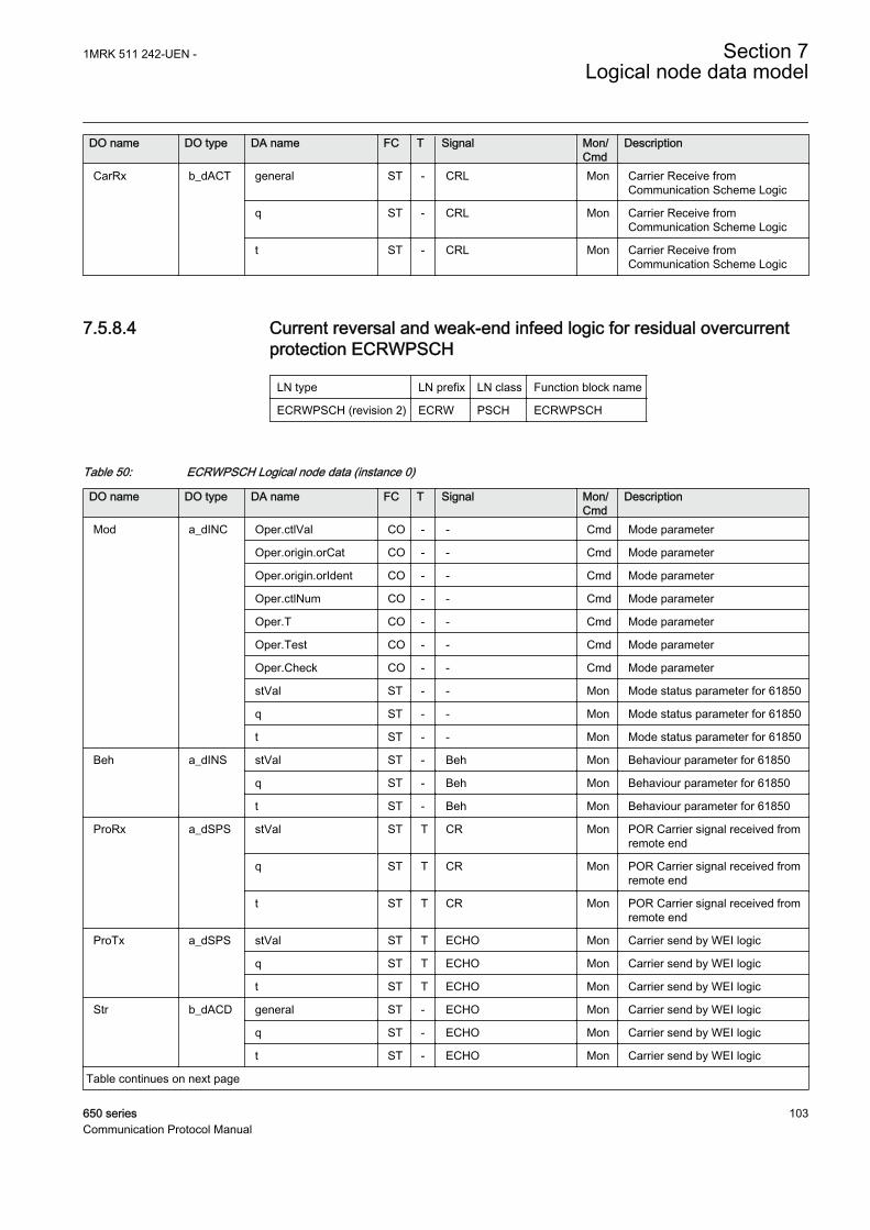
DO name DO type DA name FC T Signal Mon/Cmd
Description
CarRx b_dACT general ST - CRL Mon Carrier Receive fromCommunication Scheme Logic
q ST - CRL Mon Carrier Receive fromCommunication Scheme Logic
t ST - CRL Mon Carrier Receive fromCommunication Scheme Logic
7.5.8.4 Current reversal and weak-end infeed logic for residual overcurrentprotection ECRWPSCH
LN type LN prefix LN class Function block name
ECRWPSCH (revision 2) ECRW PSCH ECRWPSCH
Table 50: ECRWPSCH Logical node data (instance 0)
DO name DO type DA name FC T Signal Mon/Cmd
Description
Mod a_dINC Oper.ctlVal CO - - Cmd Mode parameter
Oper.origin.orCat CO - - Cmd Mode parameter
Oper.origin.orIdent CO - - Cmd Mode parameter
Oper.ctlNum CO - - Cmd Mode parameter
Oper.T CO - - Cmd Mode parameter
Oper.Test CO - - Cmd Mode parameter
Oper.Check CO - - Cmd Mode parameter
stVal ST - - Mon Mode status parameter for 61850
q ST - - Mon Mode status parameter for 61850
t ST - - Mon Mode status parameter for 61850
Beh a_dINS stVal ST - Beh Mon Behaviour parameter for 61850
q ST - Beh Mon Behaviour parameter for 61850
t ST - Beh Mon Behaviour parameter for 61850
ProRx a_dSPS stVal ST T CR Mon POR Carrier signal received fromremote end
q ST T CR Mon POR Carrier signal received fromremote end
t ST T CR Mon POR Carrier signal received fromremote end
ProTx a_dSPS stVal ST T ECHO Mon Carrier send by WEI logic
q ST T ECHO Mon Carrier send by WEI logic
t ST T ECHO Mon Carrier send by WEI logic
Str b_dACD general ST - ECHO Mon Carrier send by WEI logic
q ST - ECHO Mon Carrier send by WEI logic
t ST - ECHO Mon Carrier send by WEI logic
Table continues on next page
1MRK 511 242-UEN - Section 7Logical node data model
650 series 103Communication Protocol Manual

DO name DO type DA name FC T Signal Mon/Cmd
Description
Op b_dACT general ST T TRWEI Mon Trip of WEI logic
q ST T TRWEI Mon Trip of WEI logic
t ST T TRWEI Mon Trip of WEI logic
RvABlk b_dACT general ST - IRVL Mon Operation of current reversal logic
q ST - IRVL Mon Operation of current reversal logic
t ST - IRVL Mon Operation of current reversal logic
Echo b_dACT general ST - ECHO Mon Carrier send by WEI logic
q ST - ECHO Mon Carrier send by WEI logic
t ST - ECHO Mon Carrier send by WEI logic
WeiOp b_dACT general ST - TRWEI Mon Trip of WEI logic
q ST - TRWEI Mon Trip of WEI logic
t ST - TRWEI Mon Trip of WEI logic
7.5.9 Sensitive directional earthfault PSDE
7.5.9.1 Sensitive Directional residual over current and power protetcionSDEPSDE
LN type LN prefix LN class Function block name
SDEPSDE (revision 1) SDE PSDE SDEPSDE
Table 51: SDEPSDE Logical node data (instance 1)
DO name DO type DA name FC T Signal Mon/Cmd
Description
Mod a_dINC Oper.ctlVal CO - - Cmd Mode parameter for 61850
Oper.origin.orCat CO - - Cmd Mode parameter for 61850
Oper.origin.orIdent CO - - Cmd Mode parameter for 61850
Oper.ctlNum CO - - Cmd Mode parameter for 61850
Oper.T CO - - Cmd Mode parameter for 61850
Oper.Test CO - - Cmd Mode parameter for 61850
Oper.Check CO - - Cmd Mode parameter for 61850
stVal ST - - Mon Mode status parameter for 61850
q ST - - Mon Mode status parameter for 61850
t ST - - Mon Mode status parameter for 61850
Beh a_dINS stVal ST - Beh Mon Behaviour parameter for 61850
q ST - Beh Mon Behaviour parameter for 61850
t ST - Beh Mon Behaviour parameter for 61850
Str b_dACD general ST - START Mon General start signal
Table continues on next page
Section 7 1MRK 511 242-UEN -Logical node data model
104 650 seriesCommunication Protocol Manual

DO name DO type DA name FC T Signal Mon/Cmd
Description
Str b_dACD dirGeneral ST - STDIR Mon Direction of fault
q ST - START Mon General start signal
t ST - START Mon General start signal
Op b_dACT general ST T TRIP Mon General trip signal
q ST T TRIP Mon General trip signal
t ST T TRIP Mon General trip signal
OpResA v1_dSPS stVal ST - TRNDIN Mon Trip of non-directional residualovercurrent
q ST - TRNDIN Mon Trip of non-directional residualovercurrent
t ST - TRNDIN Mon Trip of non-directional residualovercurrent
OpResV v1_dSPS stVal ST - TRUN Mon Trip of non-directional residualovervoltage
q ST - TRUN Mon Trip of non-directional residualovervoltage
t ST - TRUN Mon Trip of non-directional residualovervoltage
StrResA v1_dSPS stVal ST - STNDIN Mon Start of non directional residualovercurrent
q ST - STNDIN Mon Start of non directional residualovercurrent
t ST - STNDIN Mon Start of non directional residualovercurrent
StrResV v1_dSPS stVal ST - STUN Mon Start of non directional residualovervoltage
q ST - STUN Mon Start of non directional residualovervoltage
t ST - STUN Mon Start of non directional residualovervoltage
StrDirResA v1_dSPS stVal ST - STDIRIN Mon Start of the directional residualovercurrent function
q ST - STDIRIN Mon Start of the directional residualovercurrent function
t ST - STDIRIN Mon Start of the directional residualovercurrent function
OpDirResA v1_dSPS stVal ST - TRDIRIN Mon Trip of the directional residualovercurrent
q ST - TRDIRIN Mon Trip of the directional residualovercurrent
t ST - TRDIRIN Mon Trip of the directional residualovercurrent
AngAV v2_dMV mag.f MX - ANG FI-RCA Mon Angle between 3U0 and 3I0minus RCA (Fi-RCA)
q MX - ANG FI-RCA Mon Angle between 3U0 and 3I0minus RCA (Fi-RCA)
Table continues on next page
1MRK 511 242-UEN - Section 7Logical node data model
650 series 105Communication Protocol Manual

DO name DO type DA name FC T Signal Mon/Cmd
Description
AngAV v2_dMV t MX - ANG FI-RCA Mon Angle between 3U0 and 3I0minus RCA (Fi-RCA)
ResA v2_dMV mag.f MX - IN Mon Measured magnitude of theresidual current 3I0
q MX - IN Mon Measured magnitude of theresidual current 3I0
t MX - IN Mon Measured magnitude of theresidual current 3I0
ResV v2_dMV mag.f MX - UN Mon Measured magnitude of theresidual voltage 3U0
q MX - UN Mon Measured magnitude of theresidual voltage 3U0
t MX - UN Mon Measured magnitude of theresidual voltage 3U0
ResP v2_dMV mag.f MX - SN Mon Measured magnitude of residualpower 3I03U0cos(Fi-RCA)
q MX - SN Mon Measured magnitude of residualpower 3I03U0cos(Fi-RCA)
t MX - SN Mon Measured magnitude of residualpower 3I03U0cos(Fi-RCA)
7.5.10 Switch onto fault logic PSOF
7.5.10.1 Automatic switch onto fault logic, voltage and current based ZCVPSOF
LN type LN prefix LN class Function block name
ZCVPSOF (revision 2) ZCV PSOF ZCVPSOF
Table 52: ZCVPSOF Logical node data (instance 1)
DO name DO type DA name FC T Signal Mon/Cmd
Description
Mod a_dINC Oper.ctlVal CO - - Cmd Mode parameter
Oper.origin.orCat CO - - Cmd Mode parameter
Oper.origin.orIdent CO - - Cmd Mode parameter
Oper.ctlNum CO - - Cmd Mode parameter
Oper.T CO - - Cmd Mode parameter
Oper.Test CO - - Cmd Mode parameter
Oper.Check CO - - Cmd Mode parameter
stVal ST - - Mon Mode status parameter for 61850
q ST - - Mon Mode status parameter for 61850
t ST - - Mon Mode status parameter for 61850
Beh a_dINS stVal ST - Beh Mon Behaviour parameter for 61850
Table continues on next page
Section 7 1MRK 511 242-UEN -Logical node data model
106 650 seriesCommunication Protocol Manual

DO name DO type DA name FC T Signal Mon/Cmd
Description
Beh a_dINS q ST - Beh Mon Behaviour parameter for 61850
t ST - Beh Mon Behaviour parameter for 61850
Op b_dACT general ST - TRIP Mon Trip output
q ST - TRIP Mon Trip output
t ST - TRIP Mon Trip output
7.5.11 Time over current PTOC
7.5.11.1 Four step residual overcurrent protection EF4PTOC
LN type LN prefix LN class Function block name
EF4LLN0 instance 1 (revision 2) - LLN0 EF4PTOC
EF4PTRC instance 1 (revision 2) EF4 PTRC EF4PTOC
EF4RDIR instance 1 (revision 2) EF4 RDIR EF4PTOC
GEN4PHAR instance 1 (revision 2) GEN4 PHAR EF4PTOC
PH1PTOC instance 1 (revision 2) PH1 PTOC EF4PTOC
PH1PTOC instance 2 (revision 2) PH1 PTOC EF4PTOC
PH1PTOC instance 3 (revision 2) PH1 PTOC EF4PTOC
PH1PTOC instance 4 (revision 2) PH1 PTOC EF4PTOC
Table 53: EF4LLN0 Logical node data (instance 1)
DO name DO type DA name FC T Signal Mon/Cmd
Description
Mod a_dINC Oper.ctlVal CO - - Cmd Mode parameter for 61850
Oper.origin.orCat CO - - Cmd Mode parameter for 61850
Oper.origin.orIdent CO - - Cmd Mode parameter for 61850
Oper.ctlNum CO - - Cmd Mode parameter for 61850
Oper.T CO - - Cmd Mode parameter for 61850
Oper.Test CO - - Cmd Mode parameter for 61850
Oper.Check CO - - Cmd Mode parameter for 61850
stVal ST - - Mon Mode status value parameter for61850
q ST - - Mon Mode status value parameter for61850
t ST - - Mon Mode status value parameter for61850
Beh a_dINS stVal ST - Beh Mon Behaviour parameter for 61850
q ST - Beh Mon Behaviour parameter for 61850
t ST - Beh Mon Behaviour parameter for 61850
1MRK 511 242-UEN - Section 7Logical node data model
650 series 107Communication Protocol Manual

Table 54: EF4PTRC Logical node data (instance 1)
DO name DO type DA name FC T Signal Mon/Cmd
Description
Beh a_dINS stVal ST - Beh Mon Behaviour parameter for 61850
q ST - Beh Mon Behaviour parameter for 61850
t ST - Beh Mon Behaviour parameter for 61850
Str b_dACD general ST - START Mon General start signal
q ST - START Mon General start signal
t ST - START Mon General start signal
Op b_dACT general ST T TRIP Mon General trip signal
q ST T TRIP Mon General trip signal
t ST T TRIP Mon General trip signal
Mod c_dINC stVal ST - - Mon Mode status value parameter for61850
q ST - - Mon Mode status value parameter for61850
t ST - - Mon Mode status value parameter for61850
Table 55: EF4RDIR Logical node data (instance 1)
DO name DO type DA name FC T Signal Mon/Cmd
Description
Beh a_dINS stVal ST - Beh Mon Behaviour parameter for 61850
q ST - Beh Mon Behaviour parameter for 61850
t ST - Beh Mon Behaviour parameter for 61850
Dir b_dACD general ST - - Mon Fault direction coded as integer
q ST - - Mon Fault direction coded as integer
t ST - - Mon Fault direction coded as integer
Mod c_dINC stVal ST - - Mon Mode status value parameter for61850
q ST - - Mon Mode status value parameter for61850
t ST - - Mon Mode status value parameter for61850
Table 56: GEN4PHAR Logical node data (instance 1)
DO name DO type DA name FC T Signal Mon/Cmd
Description
Beh a_dINS stVal ST - Beh Mon Behaviour parameter for 61850
q ST - Beh Mon Behaviour parameter for 61850
t ST - Beh Mon Behaviour parameter for 61850
Str b_dACD general ST - 2NDHARMD Mon 2nd harmonic block signal
q ST - 2NDHARMD Mon 2nd harmonic block signal
Table continues on next page
Section 7 1MRK 511 242-UEN -Logical node data model
108 650 seriesCommunication Protocol Manual

DO name DO type DA name FC T Signal Mon/Cmd
Description
Str b_dACD t ST - 2NDHARMD Mon 2nd harmonic block signal
Mod c_dINC stVal ST - - Mon Mode status value parameter for61850
q ST - - Mon Mode status value parameter for61850
t ST - - Mon Mode status value parameter for61850
Table 57: PH1PTOC Logical node data (instance 1)
DO name DO type DA name FC T Signal Mon/Cmd
Description
Beh a_dINS stVal ST - Beh Mon Behaviour parameter for 61850
q ST - Beh Mon Behaviour parameter for 61850
t ST - Beh Mon Behaviour parameter for 61850
Str b_dACD general ST - STIN1 Mon Start signal step 1
q ST - STIN1 Mon Start signal step 1
t ST - STIN1 Mon Start signal step 1
Op b_dACT general ST T TRIN1 Mon Trip signal from step 1
q ST T TRIN1 Mon Trip signal from step 1
t ST T TRIN1 Mon Trip signal from step 1
Mod c_dINC stVal ST - - Mon Mode status value parameter for61850
q ST - - Mon Mode status value parameter for61850
t ST - - Mon Mode status value parameter for61850
Table 58: PH1PTOC Logical node data (instance 2)
DO name DO type DA name FC T Signal Mon/Cmd
Description
Beh a_dINS stVal ST - Beh Mon Behaviour parameter for 61850
q ST - Beh Mon Behaviour parameter for 61850
t ST - Beh Mon Behaviour parameter for 61850
Str b_dACD general ST - STIN2 Mon Start signal step 2
q ST - STIN2 Mon Start signal step 2
t ST - STIN2 Mon Start signal step 2
Op b_dACT general ST T TRIN2 Mon Trip signal from step 2
q ST T TRIN2 Mon Trip signal from step 2
t ST T TRIN2 Mon Trip signal from step 2
Table continues on next page
1MRK 511 242-UEN - Section 7Logical node data model
650 series 109Communication Protocol Manual

DO name DO type DA name FC T Signal Mon/Cmd
Description
Mod c_dINC stVal ST - - Mon Mode status value parameter for61850
q ST - - Mon Mode status value parameter for61850
t ST - - Mon Mode status value parameter for61850
Table 59: PH1PTOC Logical node data (instance 3)
DO name DO type DA name FC T Signal Mon/Cmd
Description
Beh a_dINS stVal ST - Beh Mon Behaviour parameter for 61850
q ST - Beh Mon Behaviour parameter for 61850
t ST - Beh Mon Behaviour parameter for 61850
Str b_dACD general ST - STIN3 Mon Start signal step 3
q ST - STIN3 Mon Start signal step 3
t ST - STIN3 Mon Start signal step 3
Op b_dACT general ST T TRIN3 Mon Trip signal from step 3
q ST T TRIN3 Mon Trip signal from step 3
t ST T TRIN3 Mon Trip signal from step 3
Mod c_dINC stVal ST - - Mon Mode status value parameter for61850
q ST - - Mon Mode status value parameter for61850
t ST - - Mon Mode status value parameter for61850
Table 60: PH1PTOC Logical node data (instance 4)
DO name DO type DA name FC T Signal Mon/Cmd
Description
Beh a_dINS stVal ST - Beh Mon Behaviour parameter for 61850
q ST - Beh Mon Behaviour parameter for 61850
t ST - Beh Mon Behaviour parameter for 61850
Str b_dACD general ST - STIN4 Mon Start signal step 4
q ST - STIN4 Mon Start signal step 4
t ST - STIN4 Mon Start signal step 4
Op b_dACT general ST T TRIN4 Mon Trip signal from step 4
q ST T TRIN4 Mon Trip signal from step 4
t ST T TRIN4 Mon Trip signal from step 4
Table continues on next page
Section 7 1MRK 511 242-UEN -Logical node data model
110 650 seriesCommunication Protocol Manual

DO name DO type DA name FC T Signal Mon/Cmd
Description
Mod c_dINC stVal ST - - Mon Mode status value parameter for61850
q ST - - Mon Mode status value parameter for61850
t ST - - Mon Mode status value parameter for61850
7.5.11.2 Four step phase overcurrent protection OC4PTOC
LN type LN prefix LN class Function block name
GEN4PHAR instance 1 (revision 2) GEN4 PHAR OC4PTOC
OC4LLN0 instance 1 (revision 1) - LLN0 OC4PTOC
PH3PTOC instance 1 (revision 1) PH3 PTOC OC4PTOC
PH3PTOC instance 2 (revision 1) PH3 PTOC OC4PTOC
PH3PTOC instance 3 (revision 1) PH3 PTOC OC4PTOC
PH3PTOC instance 4 (revision 1) PH3 PTOC OC4PTOC
PH3PTRC instance 1 (revision 1) PH3 PTRC OC4PTOC
Table 61: GEN4PHAR Logical node data (instance 1)
DO name DO type DA name FC T Signal Mon/Cmd
Description
Beh a_dINS stVal ST - Beh Mon Behaviour parameter for 61850
q ST - Beh Mon Behaviour parameter for 61850
t ST - Beh Mon Behaviour parameter for 61850
Str b_dACD general ST - - Mon Block from second harmonicdetection
q ST - - Mon Block from second harmonicdetection
t ST - - Mon Block from second harmonicdetection
Mod c_dINC stVal ST - - Mon Mode status parameter for 61850
q ST - - Mon Mode status parameter for 61850
t ST - - Mon Mode status parameter for 61850
Table 62: OC4LLN0 Logical node data (instance 1)
DO name DO type DA name FC T Signal Mon/Cmd
Description
Mod a_dINC Oper.ctlVal CO - - Cmd Mode parameter
Oper.origin.orCat CO - - Cmd Mode parameter
Oper.origin.orIdent CO - - Cmd Mode parameter
Table continues on next page
1MRK 511 242-UEN - Section 7Logical node data model
650 series 111Communication Protocol Manual

DO name DO type DA name FC T Signal Mon/Cmd
Description
Mod a_dINC Oper.ctlNum CO - - Cmd Mode parameter
Oper.T CO - - Cmd Mode parameter
Oper.Test CO - - Cmd Mode parameter
Oper.Check CO - - Cmd Mode parameter
stVal ST - - Mon Mode status parameter for 61850
q ST - - Mon Mode status parameter for 61850
t ST - - Mon Mode status parameter for 61850
Beh a_dINS stVal ST - Beh Mon Behaviour parameter for 61850
q ST - Beh Mon Behaviour parameter for 61850
t ST - Beh Mon Behaviour parameter for 61850
Table 63: PH3PTOC Logical node data (instance 1)
DO name DO type DA name FC T Signal Mon/Cmd
Description
Beh a_dINS stVal ST - Beh Mon Behaviour parameter for 61850
q ST - Beh Mon Behaviour parameter for 61850
t ST - Beh Mon Behaviour parameter for 61850
Str b_dACD general ST - ST1 Mon Start signal from step 1
q ST - ST1 Mon Start signal from step 1
t ST - ST1 Mon Start signal from step 1
Op b_dACT general ST T TR1 Mon Trip signal from step 1
q ST T TR1 Mon Trip signal from step 1
t ST T TR1 Mon Trip signal from step 1
Mod c_dINC stVal ST - - Mon Mode status parameter for 61850
q ST - - Mon Mode status parameter for 61850
t ST - - Mon Mode status parameter for 61850
Table 64: PH3PTOC Logical node data (instance 2)
DO name DO type DA name FC T Signal Mon/Cmd
Description
Beh a_dINS stVal ST - Beh Mon Behaviour parameter for 61850
q ST - Beh Mon Behaviour parameter for 61850
t ST - Beh Mon Behaviour parameter for 61850
Str b_dACD general ST - ST2 Mon Start signal from step 2
q ST - ST2 Mon Start signal from step 2
t ST - ST2 Mon Start signal from step 2
Op b_dACT general ST T TR2 Mon Trip signal from step 2
q ST T TR2 Mon Trip signal from step 2
Table continues on next page
Section 7 1MRK 511 242-UEN -Logical node data model
112 650 seriesCommunication Protocol Manual
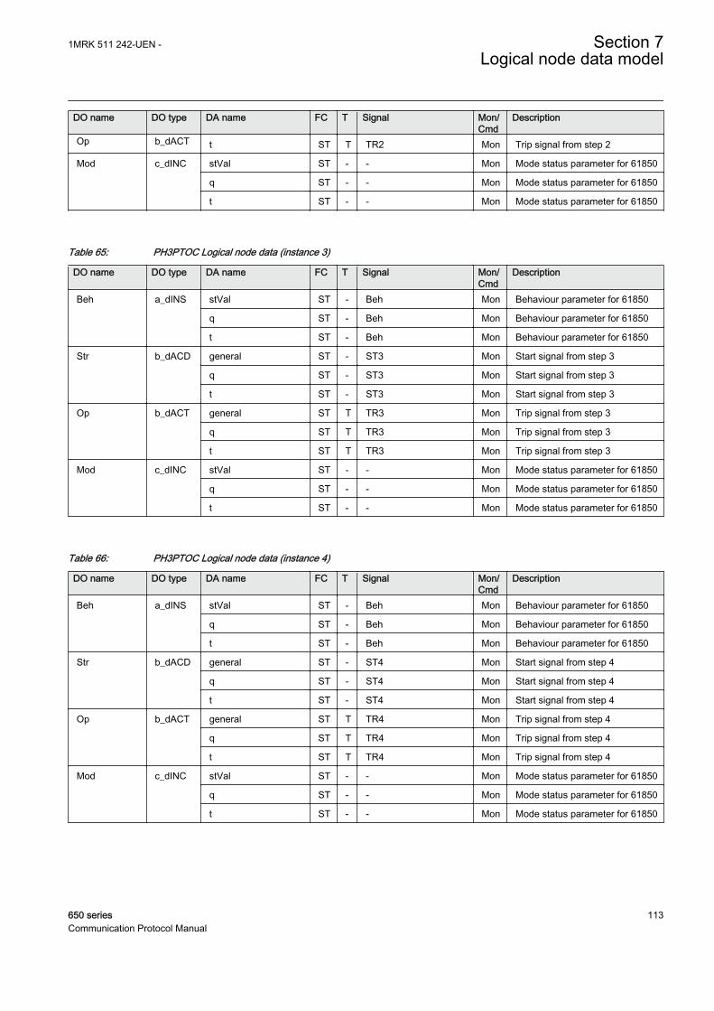
DO name DO type DA name FC T Signal Mon/Cmd
Description
Op b_dACT t ST T TR2 Mon Trip signal from step 2
Mod c_dINC stVal ST - - Mon Mode status parameter for 61850
q ST - - Mon Mode status parameter for 61850
t ST - - Mon Mode status parameter for 61850
Table 65: PH3PTOC Logical node data (instance 3)
DO name DO type DA name FC T Signal Mon/Cmd
Description
Beh a_dINS stVal ST - Beh Mon Behaviour parameter for 61850
q ST - Beh Mon Behaviour parameter for 61850
t ST - Beh Mon Behaviour parameter for 61850
Str b_dACD general ST - ST3 Mon Start signal from step 3
q ST - ST3 Mon Start signal from step 3
t ST - ST3 Mon Start signal from step 3
Op b_dACT general ST T TR3 Mon Trip signal from step 3
q ST T TR3 Mon Trip signal from step 3
t ST T TR3 Mon Trip signal from step 3
Mod c_dINC stVal ST - - Mon Mode status parameter for 61850
q ST - - Mon Mode status parameter for 61850
t ST - - Mon Mode status parameter for 61850
Table 66: PH3PTOC Logical node data (instance 4)
DO name DO type DA name FC T Signal Mon/Cmd
Description
Beh a_dINS stVal ST - Beh Mon Behaviour parameter for 61850
q ST - Beh Mon Behaviour parameter for 61850
t ST - Beh Mon Behaviour parameter for 61850
Str b_dACD general ST - ST4 Mon Start signal from step 4
q ST - ST4 Mon Start signal from step 4
t ST - ST4 Mon Start signal from step 4
Op b_dACT general ST T TR4 Mon Trip signal from step 4
q ST T TR4 Mon Trip signal from step 4
t ST T TR4 Mon Trip signal from step 4
Mod c_dINC stVal ST - - Mon Mode status parameter for 61850
q ST - - Mon Mode status parameter for 61850
t ST - - Mon Mode status parameter for 61850
1MRK 511 242-UEN - Section 7Logical node data model
650 series 113Communication Protocol Manual

Table 67: PH3PTRC Logical node data (instance 1)
DO name DO type DA name FC T Signal Mon/Cmd
Description
Str a_dACD general ST - START Mon General start signal
phsA ST - STL1 Mon Start signal from phase L1
dirPhsA ST - DIRL1 Mon Direction for phase L1
phsB ST - STL2 Mon Start signal from phase L2
dirPhsB ST - DIRL2 Mon Direction for phase L2
phsC ST - STL3 Mon Start signal from phase L3
dirPhsC ST - DIRL3 Mon Direction for phase L3
q ST - START Mon General start signal
t ST - START Mon General start signal
Beh a_dINS stVal ST - Beh Mon Behaviour parameter for 61850
q ST - Beh Mon Behaviour parameter for 61850
t ST - Beh Mon Behaviour parameter for 61850
Op b_dACT general ST T TRIP Mon General trip signal
q ST T TRIP Mon General trip signal
t ST T TRIP Mon General trip signal
Mod c_dINC stVal ST - - Mon Mode status parameter for 61850
q ST - - Mon Mode status parameter for 61850
t ST - - Mon Mode status parameter for 61850
7.5.11.3 Stub protection STBPTOC
LN type LN prefix LN class Function block name
STBPTOC (revision 1) STB PTOC STBPTOC
Table 68: STBPTOC Logical node data (instance 0)
DO name DO type DA name FC T Signal Mon/Cmd
Description
Mod a_dINC Oper.ctlVal CO - - Cmd Mode parameter
Oper.origin.orCat CO - - Cmd Mode parameter
Oper.origin.orIdent CO - - Cmd Mode parameter
Oper.ctlNum CO - - Cmd Mode parameter
Oper.T CO - - Cmd Mode parameter
Oper.Test CO - - Cmd Mode parameter
Oper.Check CO - - Cmd Mode parameter
stVal ST - - Mon Mode status parameter for 61850
q ST - - Mon Mode status parameter for 61850
t ST - - Mon Mode status parameter for 61850
Table continues on next page
Section 7 1MRK 511 242-UEN -Logical node data model
114 650 seriesCommunication Protocol Manual

DO name DO type DA name FC T Signal Mon/Cmd
Description
Beh a_dINS stVal ST - Beh Mon Behaviour parameter for 61850
q ST - Beh Mon Behaviour parameter for 61850
t ST - Beh Mon Behaviour parameter for 61850
Str b_dACD general ST - START Mon General start signal
q ST - START Mon General start signal
t ST - START Mon General start signal
Op b_dACT general ST T TRIP Mon General trip signal
q ST T TRIP Mon General trip signal
t ST T TRIP Mon General trip signal
7.5.11.4 Broken conductor check BRCPTOC
LN type LN prefix LN class Function block name
BRCPTOC (revision 1) BRC PTOC BRCPTOC
Table 69: BRCPTOC Logical node data (instance 0)
DO name DO type DA name FC T Signal Mon/Cmd
Description
Mod a_dINC Oper.ctlVal CO - - Cmd Mode parameter
Oper.origin.orCat CO - - Cmd Mode parameter
Oper.origin.orIdent CO - - Cmd Mode parameter
Oper.ctlNum CO - - Cmd Mode parameter
Oper.T CO - - Cmd Mode parameter
Oper.Test CO - - Cmd Mode parameter
Oper.Check CO - - Cmd Mode parameter
stVal ST - - Mon Mode status parameter for 61850
q ST - - Mon Mode status parameter for 61850
t ST - - Mon Mode status parameter for 61850
Beh a_dINS stVal ST - Beh Mon Behaviour parameter for 61850
q ST - Beh Mon Behaviour parameter for 61850
t ST - Beh Mon Behaviour parameter for 61850
Str b_dACD general ST - START Mon Start signal of the protection logic
q ST - START Mon Start signal of the protection logic
t ST - START Mon Start signal of the protection logic
Op b_dACT general ST T TRIP Mon Operate signal of the protectionlogic
q ST T TRIP Mon Operate signal of the protectionlogic
Table continues on next page
1MRK 511 242-UEN - Section 7Logical node data model
650 series 115Communication Protocol Manual
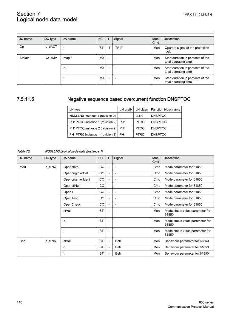
DO name DO type DA name FC T Signal Mon/Cmd
Description
Op b_dACT t ST T TRIP Mon Operate signal of the protectionlogic
StrDur v2_dMV mag.f MX - - Mon Start duration in percents of thetotal operating time
q MX - - Mon Start duration in percents of thetotal operating time
t MX - - Mon Start duration in percents of thetotal operating time
7.5.11.5 Negative sequence based overcurrent function DNSPTOC
LN type LN prefix LN class Function block name
NSDLLN0 instance 1 (revision 2) - LLN0 DNSPTOC
PH1PTOC instance 1 (revision 2) PH1 PTOC DNSPTOC
PH1PTOC instance 2 (revision 2) PH1 PTOC DNSPTOC
PH1PTRC instance 1 (revision 1) PH1 PTRC DNSPTOC
Table 70: NSDLLN0 Logical node data (instance 1)
DO name DO type DA name FC T Signal Mon/Cmd
Description
Mod a_dINC Oper.ctlVal CO - - Cmd Mode parameter for 61850
Oper.origin.orCat CO - - Cmd Mode parameter for 61850
Oper.origin.orIdent CO - - Cmd Mode parameter for 61850
Oper.ctlNum CO - - Cmd Mode parameter for 61850
Oper.T CO - - Cmd Mode parameter for 61850
Oper.Test CO - - Cmd Mode parameter for 61850
Oper.Check CO - - Cmd Mode parameter for 61850
stVal ST - - Mon Mode status value parameter for61850
q ST - - Mon Mode status value parameter for61850
t ST - - Mon Mode status value parameter for61850
Beh a_dINS stVal ST - Beh Mon Behaviour parameter for 61850
q ST - Beh Mon Behaviour parameter for 61850
t ST - Beh Mon Behaviour parameter for 61850
Section 7 1MRK 511 242-UEN -Logical node data model
116 650 seriesCommunication Protocol Manual

Table 71: PH1PTOC Logical node data (instance 1)
DO name DO type DA name FC T Signal Mon/Cmd
Description
Beh a_dINS stVal ST - Beh Mon Behaviour parameter for 61850
q ST - Beh Mon Behaviour parameter for 61850
t ST - Beh Mon Behaviour parameter for 61850
Str b_dACD general ST - STOC1 Mon Start signal from step 1 (OC1)
dirGeneral ST - DIROC1 Mon Directional mode of step 1 (non-directional, forward, reverse)
q ST - STOC1 Mon Start signal from step 1 (OC1)
t ST - STOC1 Mon Start signal from step 1 (OC1)
Op b_dACT general ST T TROC1 Mon Trip signal from step 1 (OC1)
q ST T TROC1 Mon Trip signal from step 1 (OC1)
t ST T TROC1 Mon Trip signal from step 1 (OC1)
Mod c_dINC stVal ST - - Mon Mode status value parameter for61850
q ST - - Mon Mode status value parameter for61850
t ST - - Mon Mode status value parameter for61850
Table 72: PH1PTOC Logical node data (instance 2)
DO name DO type DA name FC T Signal Mon/Cmd
Description
Beh a_dINS stVal ST - Beh Mon Behaviour parameter for 61850
q ST - Beh Mon Behaviour parameter for 61850
t ST - Beh Mon Behaviour parameter for 61850
Str b_dACD general ST - STOC2 Mon Start signal from step 2 (OC2)
dirGeneral ST - DIROC2 Mon Directional mode of step 2 (non-directional, forward, reverse)
q ST - STOC2 Mon Start signal from step 2 (OC2)
t ST - STOC2 Mon Start signal from step 2 (OC2)
Op b_dACT general ST T TROC2 Mon Trip signal from step 2 (OC2)
q ST T TROC2 Mon Trip signal from step 2 (OC2)
t ST T TROC2 Mon Trip signal from step 2 (OC2)
Mod c_dINC stVal ST - - Mon Mode status value parameter for61850
q ST - - Mon Mode status value parameter for61850
t ST - - Mon Mode status value parameter for61850
1MRK 511 242-UEN - Section 7Logical node data model
650 series 117Communication Protocol Manual

Table 73: PH1PTRC Logical node data (instance 1)
DO name DO type DA name FC T Signal Mon/Cmd
Description
Beh a_dINS stVal ST - Beh Mon Behaviour parameter for 61850
q ST - Beh Mon Behaviour parameter for 61850
t ST - Beh Mon Behaviour parameter for 61850
Str b_dACD general ST - START Mon General start signal
q ST - START Mon General start signal
t ST - START Mon General start signal
Op b_dACT general ST T TRIP Mon General trip signal
q ST T TRIP Mon General trip signal
t ST T TRIP Mon General trip signal
Mod c_dINC stVal ST - - Mon Mode status value parameter for61850
q ST - - Mon Mode status value parameter for61850
t ST - - Mon Mode status value parameter for61850
7.5.11.6 Negativ sequence time overcurrent protection for machines NS2PTOC
LN type LN prefix LN class Function block name
NS2LLN0 instance 1 (revision 1) - LLN0 NS2PTOC
NS2PTOC instance 1 (revision 1) NS2 PTOC NS2PTOC
NS2PTOC instance 2 (revision 1) NS2 PTOC NS2PTOC
NS2PTRC instance 1 (revision 1) NS2 PTRC NS2PTOC
Table 74: NS2LLN0 Logical node data (instance 1)
DO name DO type DA name FC T Signal Mon/Cmd
Description
Mod a_dINC Oper.ctlVal CO - - Cmd Mode parameter for 61850
Oper.origin.orCat CO - - Cmd Mode parameter for 61850
Oper.origin.orIdent CO - - Cmd Mode parameter for 61850
Oper.ctlNum CO - - Cmd Mode parameter for 61850
Oper.T CO - - Cmd Mode parameter for 61850
Oper.Test CO - - Cmd Mode parameter for 61850
Oper.Check CO - - Cmd Mode parameter for 61850
Beh a_dINS stVal ST - Beh Mon Behaviour parameter for 61850
q ST - Beh Mon Behaviour parameter for 61850
t ST - Beh Mon Behaviour parameter for 61850
Alm a_dSPS stVal ST - ALARM Mon Alarm signal
Table continues on next page
Section 7 1MRK 511 242-UEN -Logical node data model
118 650 seriesCommunication Protocol Manual

DO name DO type DA name FC T Signal Mon/Cmd
Description
Alm a_dSPS q ST - ALARM Mon Alarm signal
t ST - ALARM Mon Alarm signal
NSCurr v2_dMV mag.f MX - NSCURR Mon Negative sequence current inprimary amps
q MX - NSCURR Mon Negative sequence current inprimary amps
t MX - NSCURR Mon Negative sequence current inprimary amps
Table 75: NS2PTOC Logical node data (instance 1)
DO name DO type DA name FC T Signal Mon/Cmd
Description
Beh a_dINS stVal ST - Beh Mon Behaviour parameter for 61850
q ST - Beh Mon Behaviour parameter for 61850
t ST - Beh Mon Behaviour parameter for 61850
Str b_dACD general ST - ST1 Mon Start signal for step 1
q ST - ST1 Mon Start signal for step 1
t ST - ST1 Mon Start signal for step 1
Op b_dACT general ST T TR1 Mon Trip signal for step 1
q ST T TR1 Mon Trip signal for step 1
t ST T TR1 Mon Trip signal for step 1
Mod c_dINC stVal ST - - Mon Mode status parameter for 61850
q ST - - Mon Mode status parameter for 61850
t ST - - Mon Mode status parameter for 61850
Table 76: NS2PTOC Logical node data (instance 2)
DO name DO type DA name FC T Signal Mon/Cmd
Description
Beh a_dINS stVal ST - Beh Mon Behaviour parameter for 61850
q ST - Beh Mon Behaviour parameter for 61850
t ST - Beh Mon Behaviour parameter for 61850
Str b_dACD general ST - ST2 Mon Start signal for step 2
q ST - ST2 Mon Start signal for step 2
t ST - ST2 Mon Start signal for step 2
Op b_dACT general ST T TR2 Mon Trip signal for step 2
q ST T TR2 Mon Trip signal for step 2
t ST T TR2 Mon Trip signal for step 2
Mod c_dINC stVal ST - - Mon Mode status parameter for 61850
q ST - - Mon Mode status parameter for 61850
t ST - - Mon Mode status parameter for 61850
1MRK 511 242-UEN - Section 7Logical node data model
650 series 119Communication Protocol Manual
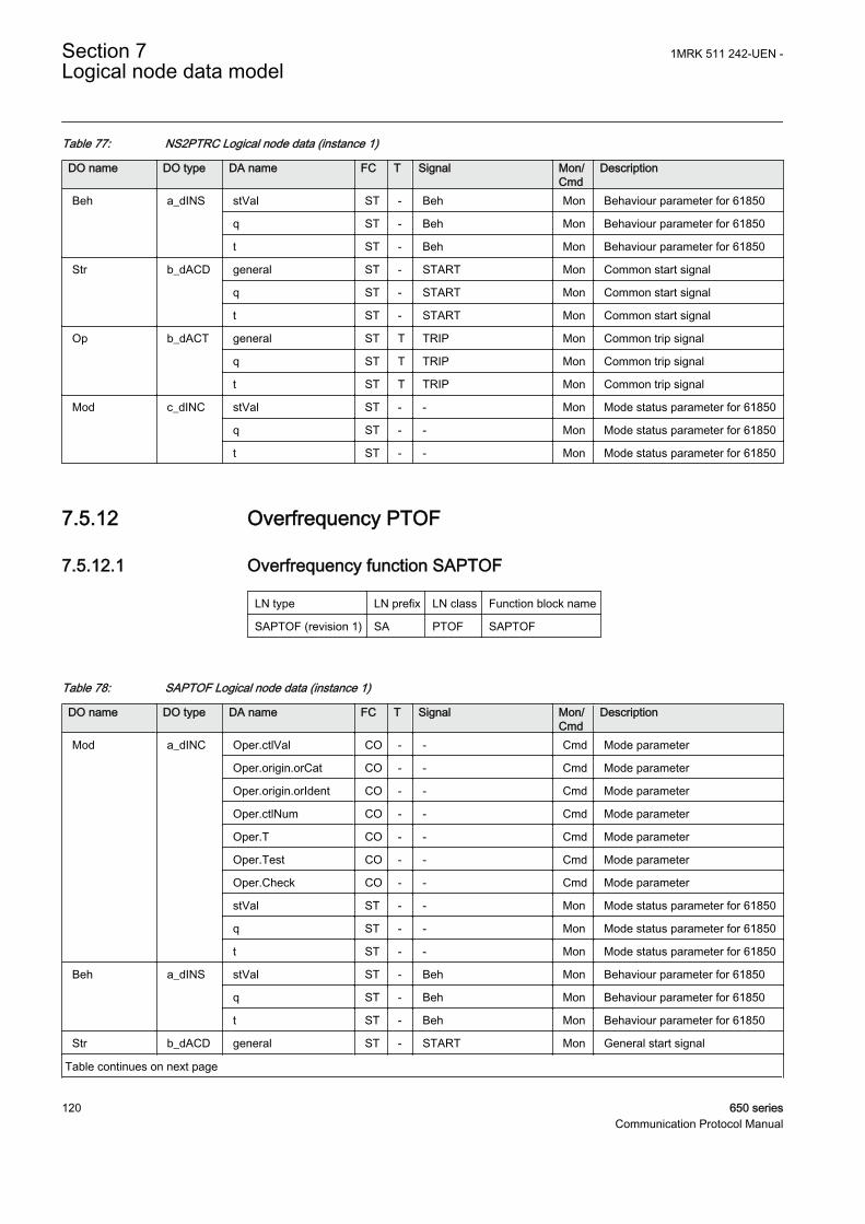
Table 77: NS2PTRC Logical node data (instance 1)
DO name DO type DA name FC T Signal Mon/Cmd
Description
Beh a_dINS stVal ST - Beh Mon Behaviour parameter for 61850
q ST - Beh Mon Behaviour parameter for 61850
t ST - Beh Mon Behaviour parameter for 61850
Str b_dACD general ST - START Mon Common start signal
q ST - START Mon Common start signal
t ST - START Mon Common start signal
Op b_dACT general ST T TRIP Mon Common trip signal
q ST T TRIP Mon Common trip signal
t ST T TRIP Mon Common trip signal
Mod c_dINC stVal ST - - Mon Mode status parameter for 61850
q ST - - Mon Mode status parameter for 61850
t ST - - Mon Mode status parameter for 61850
7.5.12 Overfrequency PTOF
7.5.12.1 Overfrequency function SAPTOF
LN type LN prefix LN class Function block name
SAPTOF (revision 1) SA PTOF SAPTOF
Table 78: SAPTOF Logical node data (instance 1)
DO name DO type DA name FC T Signal Mon/Cmd
Description
Mod a_dINC Oper.ctlVal CO - - Cmd Mode parameter
Oper.origin.orCat CO - - Cmd Mode parameter
Oper.origin.orIdent CO - - Cmd Mode parameter
Oper.ctlNum CO - - Cmd Mode parameter
Oper.T CO - - Cmd Mode parameter
Oper.Test CO - - Cmd Mode parameter
Oper.Check CO - - Cmd Mode parameter
stVal ST - - Mon Mode status parameter for 61850
q ST - - Mon Mode status parameter for 61850
t ST - - Mon Mode status parameter for 61850
Beh a_dINS stVal ST - Beh Mon Behaviour parameter for 61850
q ST - Beh Mon Behaviour parameter for 61850
t ST - Beh Mon Behaviour parameter for 61850
Str b_dACD general ST - START Mon General start signal
Table continues on next page
Section 7 1MRK 511 242-UEN -Logical node data model
120 650 seriesCommunication Protocol Manual

DO name DO type DA name FC T Signal Mon/Cmd
Description
Str b_dACD q ST - START Mon General start signal
t ST - START Mon General start signal
Op b_dACT general ST T TRIP Mon General trip signal
q ST T TRIP Mon General trip signal
t ST T TRIP Mon General trip signal
BlkLoMg v1_dSPS stVal ST - BLKDMAGN Mon Measurement blocked due to lowamplitude
q ST - BLKDMAGN Mon Measurement blocked due to lowamplitude
t ST - BLKDMAGN Mon Measurement blocked due to lowamplitude
7.5.13 Overvoltage PTOV
7.5.13.1 Two step overvoltage protection OV2PTOV
LN type LN prefix LN class Function block name
GEN2LLN0 instance 1 (revision 1) - LLN0 OV2PTOV
OV2PTOV instance 1 (revision 1) OV2 PTOV OV2PTOV
OV2PTOV instance 2 (revision 1) OV2 PTOV OV2PTOV
PH3PTRC instance 1 (revision 1) PH3 PTRC OV2PTOV
Table 79: GEN2LLN0 Logical node data (instance 1)
DO name DO type DA name FC T Signal Mon/Cmd
Description
Mod a_dINC Oper.ctlVal CO - - Cmd Mode parameter
Oper.origin.orCat CO - - Cmd Mode parameter
Oper.origin.orIdent CO - - Cmd Mode parameter
Oper.ctlNum CO - - Cmd Mode parameter
Oper.T CO - - Cmd Mode parameter
Oper.Test CO - - Cmd Mode parameter
Oper.Check CO - - Cmd Mode parameter
stVal ST - - Mon Mode status parameter for 61850
q ST - - Mon Mode status parameter for 61850
t ST - - Mon Mode status parameter for 61850
Beh a_dINS stVal ST - Beh Mon Behaviour parameter for 61850
q ST - Beh Mon Behaviour parameter for 61850
t ST - Beh Mon Behaviour parameter for 61850
1MRK 511 242-UEN - Section 7Logical node data model
650 series 121Communication Protocol Manual

Table 80: OV2PTOV Logical node data (instance 1)
DO name DO type DA name FC T Signal Mon/Cmd
Description
Str a_dACD general ST - ST1 Mon Start signal from step 1
phsA ST - ST1L1 Mon Start signal from step 1 phase L1
phsB ST - ST1L2 Mon Start signal from step 1 phase L2
phsC ST - ST1L3 Mon Start signal from step 1 phase L3
q ST - ST1 Mon Start signal from step 1
t ST - ST1 Mon Start signal from step 1
Beh a_dINS stVal ST - Beh Mon Behaviour parameter for 61850
q ST - Beh Mon Behaviour parameter for 61850
t ST - Beh Mon Behaviour parameter for 61850
Op b_dACT general ST T TR1 Mon Trip signal from step 1
q ST T TR1 Mon Trip signal from step 1
t ST T TR1 Mon Trip signal from step 1
Mod c_dINC stVal ST - - Mon Mode status parameter for 61850
q ST - - Mon Mode status parameter for 61850
t ST - - Mon Mode status parameter for 61850
Table 81: OV2PTOV Logical node data (instance 2)
DO name DO type DA name FC T Signal Mon/Cmd
Description
Str a_dACD general ST - ST2 Mon Start signal from step 2
phsA ST - - Mon Start signal from step 2 phase L1
phsB ST - - Mon Start signal from step 2 phase L2
phsC ST - - Mon Start signal from step 2 phase L3
q ST - ST2 Mon Start signal from step 2
t ST - ST2 Mon Start signal from step 2
Beh a_dINS stVal ST - Beh Mon Behaviour parameter for 61850
q ST - Beh Mon Behaviour parameter for 61850
t ST - Beh Mon Behaviour parameter for 61850
Op b_dACT general ST T TR2 Mon Trip signal from step 2
q ST T TR2 Mon Trip signal from step 2
t ST T TR2 Mon Trip signal from step 2
Mod c_dINC stVal ST - - Mon Mode status parameter for 61850
q ST - - Mon Mode status parameter for 61850
t ST - - Mon Mode status parameter for 61850
Section 7 1MRK 511 242-UEN -Logical node data model
122 650 seriesCommunication Protocol Manual

Table 82: PH3PTRC Logical node data (instance 1)
DO name DO type DA name FC T Signal Mon/Cmd
Description
Str a_dACD general ST - START Mon General start signal
q ST - START Mon General start signal
t ST - START Mon General start signal
Beh a_dINS stVal ST - Beh Mon Behaviour parameter for 61850
q ST - Beh Mon Behaviour parameter for 61850
t ST - Beh Mon Behaviour parameter for 61850
Op b_dACT general ST T TRIP Mon General trip signal
q ST T TRIP Mon General trip signal
t ST T TRIP Mon General trip signal
Mod c_dINC stVal ST - - Mon Mode status parameter for 61850
q ST - - Mon Mode status parameter for 61850
t ST - - Mon Mode status parameter for 61850
7.5.13.2 Two step residual overvoltage protection ROV2PTOV
LN type LN prefix LN class Function block name
GEN2LLN0 instance 1 (revision 1) - LLN0 ROV2PTOV
PH1PTRC instance 1 (revision 1) PH1 PTRC ROV2PTOV
ROV2PTOV instance 1 (revision 1) ROV2 PTOV ROV2PTOV
ROV2PTOV instance 2 (revision 1) ROV2 PTOV ROV2PTOV
Table 83: GEN2LLN0 Logical node data (instance 1)
DO name DO type DA name FC T Signal Mon/Cmd
Description
Mod a_dINC Oper.ctlVal CO - - Cmd Mode parameter
Oper.origin.orCat CO - - Cmd Mode parameter
Oper.origin.orIdent CO - - Cmd Mode parameter
Oper.ctlNum CO - - Cmd Mode parameter
Oper.T CO - - Cmd Mode parameter
Oper.Test CO - - Cmd Mode parameter
Oper.Check CO - - Cmd Mode parameter
stVal ST - - Mon Mode status parameter for 61850
q ST - - Mon Mode status parameter for 61850
t ST - - Mon Mode status parameter for 61850
Beh a_dINS stVal ST - Beh Mon Behaviour parameter for 61850
q ST - Beh Mon Behaviour parameter for 61850
t ST - Beh Mon Behaviour parameter for 61850
1MRK 511 242-UEN - Section 7Logical node data model
650 series 123Communication Protocol Manual

Table 84: PH1PTRC Logical node data (instance 1)
DO name DO type DA name FC T Signal Mon/Cmd
Description
Beh a_dINS stVal ST - Beh Mon Behaviour parameter for 61850
q ST - Beh Mon Behaviour parameter for 61850
t ST - Beh Mon Behaviour parameter for 61850
Str b_dACD general ST - START Mon General start signal
q ST - START Mon General start signal
t ST - START Mon General start signal
Op b_dACT general ST T TRIP Mon General trip signal
q ST T TRIP Mon General trip signal
t ST T TRIP Mon General trip signal
Mod c_dINC stVal ST - - Mon Mode status parameter for 61850
q ST - - Mon Mode status parameter for 61850
t ST - - Mon Mode status parameter for 61850
Table 85: ROV2PTOV Logical node data (instance 1)
DO name DO type DA name FC T Signal Mon/Cmd
Description
Beh a_dINS stVal ST - Beh Mon Behaviour parameter for 61850
q ST - Beh Mon Behaviour parameter for 61850
t ST - Beh Mon Behaviour parameter for 61850
Str b_dACD general ST - ST1 Mon Start signal from step 1
q ST - ST1 Mon Start signal from step 1
t ST - ST1 Mon Start signal from step 1
Op b_dACT general ST T TR1 Mon Trip signal from step 1
q ST T TR1 Mon Trip signal from step 1
t ST T TR1 Mon Trip signal from step 1
Mod c_dINC stVal ST - - Mon Mode status parameter for 61850
q ST - - Mon Mode status parameter for 61850
t ST - - Mon Mode status parameter for 61850
Table 86: ROV2PTOV Logical node data (instance 2)
DO name DO type DA name FC T Signal Mon/Cmd
Description
Beh a_dINS stVal ST - Beh Mon Behaviour parameter for 61850
q ST - Beh Mon Behaviour parameter for 61850
t ST - Beh Mon Behaviour parameter for 61850
Str b_dACD general ST - ST2 Mon Start signal from step 2
q ST - ST2 Mon Start signal from step 2
Table continues on next page
Section 7 1MRK 511 242-UEN -Logical node data model
124 650 seriesCommunication Protocol Manual
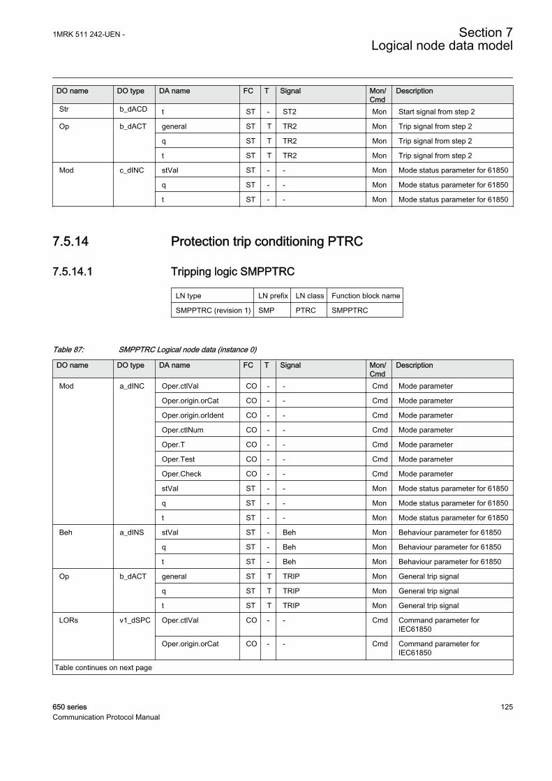
DO name DO type DA name FC T Signal Mon/Cmd
Description
Str b_dACD t ST - ST2 Mon Start signal from step 2
Op b_dACT general ST T TR2 Mon Trip signal from step 2
q ST T TR2 Mon Trip signal from step 2
t ST T TR2 Mon Trip signal from step 2
Mod c_dINC stVal ST - - Mon Mode status parameter for 61850
q ST - - Mon Mode status parameter for 61850
t ST - - Mon Mode status parameter for 61850
7.5.14 Protection trip conditioning PTRC
7.5.14.1 Tripping logic SMPPTRC
LN type LN prefix LN class Function block name
SMPPTRC (revision 1) SMP PTRC SMPPTRC
Table 87: SMPPTRC Logical node data (instance 0)
DO name DO type DA name FC T Signal Mon/Cmd
Description
Mod a_dINC Oper.ctlVal CO - - Cmd Mode parameter
Oper.origin.orCat CO - - Cmd Mode parameter
Oper.origin.orIdent CO - - Cmd Mode parameter
Oper.ctlNum CO - - Cmd Mode parameter
Oper.T CO - - Cmd Mode parameter
Oper.Test CO - - Cmd Mode parameter
Oper.Check CO - - Cmd Mode parameter
stVal ST - - Mon Mode status parameter for 61850
q ST - - Mon Mode status parameter for 61850
t ST - - Mon Mode status parameter for 61850
Beh a_dINS stVal ST - Beh Mon Behaviour parameter for 61850
q ST - Beh Mon Behaviour parameter for 61850
t ST - Beh Mon Behaviour parameter for 61850
Op b_dACT general ST T TRIP Mon General trip signal
q ST T TRIP Mon General trip signal
t ST T TRIP Mon General trip signal
LORs v1_dSPC Oper.ctlVal CO - - Cmd Command parameter forIEC61850
Oper.origin.orCat CO - - Cmd Command parameter forIEC61850
Table continues on next page
1MRK 511 242-UEN - Section 7Logical node data model
650 series 125Communication Protocol Manual

DO name DO type DA name FC T Signal Mon/Cmd
Description
LORs v1_dSPC Oper.origin.orIdent CO - - Cmd Command parameter forIEC61850
Oper.ctlNum CO - - Cmd Command parameter forIEC61850
Oper.T CO - - Cmd Command parameter forIEC61850
Oper.Test CO - - Cmd Command parameter forIEC61850
Oper.Check CO - - Cmd Command parameter forIEC61850
ClsLO v1_dSPS stVal ST - CLLKOUT Mon Circuit breaker lockout output (setuntil reset)
q ST - CLLKOUT Mon Circuit breaker lockout output (setuntil reset)
t ST - CLLKOUT Mon Circuit breaker lockout output (setuntil reset)
7.5.15 Thermal overload PTTR
7.5.15.1 Thermal overload protection, one time constant LPTTR
LN type LN prefix LN class Function block name
LPTTR (revision 5) L PTTR LPTTR
Table 88: LPTTR Logical node data (instance 0)
DO name DO type DA name FC T Signal Mon/Cmd
Description
Mod a_dINC Oper.ctlVal CO - - Cmd Mode parameter
Oper.origin.orCat CO - - Cmd Mode parameter
Oper.origin.orIdent CO - - Cmd Mode parameter
Oper.ctlNum CO - - Cmd Mode parameter
Oper.T CO - - Cmd Mode parameter
Oper.Test CO - - Cmd Mode parameter
Oper.Check CO - - Cmd Mode parameter
stVal ST - - Mon Mode status parameter for 61850
q ST - - Mon Mode status parameter for 61850
t ST - - Mon Mode status parameter for 61850
Beh a_dINS stVal ST - Beh Mon Behaviour parameter for 61850
q ST - Beh Mon Behaviour parameter for 61850
t ST - Beh Mon Behaviour parameter for 61850
AlmThm a_dSPS stVal ST - ALARM Mon Alarm signal
Table continues on next page
Section 7 1MRK 511 242-UEN -Logical node data model
126 650 seriesCommunication Protocol Manual

DO name DO type DA name FC T Signal Mon/Cmd
Description
AlmThm a_dSPS q ST - ALARM Mon Alarm signal
t ST - ALARM Mon Alarm signal
Str b_dACD general ST - START Mon General start signal
q ST - START Mon General start signal
t ST - START Mon General start signal
Op b_dACT general ST T TRIP Mon General trip signal
q ST T TRIP Mon General trip signal
t ST T TRIP Mon General trip signal
Tmp b_dMV mag.f MX - TEMP Mon Calculated temperature of thedevice
q MX - TEMP Mon Calculated temperature of thedevice
t MX - TEMP Mon Calculated temperature of thedevice
TmpRl b_dMV mag.f MX - TERMLOAD Mon Temperature relative to operatetemperature
q MX - TERMLOAD Mon Temperature relative to operatetemperature
t MX - TERMLOAD Mon Temperature relative to operatetemperature
TmmOp v1_dINS stVal ST - TTRIP Mon Estimated time to trip (in min)
q ST - TTRIP Mon Estimated time to trip (in min)
t ST - TTRIP Mon Estimated time to trip (in min)
TmmRsLO v1_dINS stVal ST - TENRECL Mon Estimated time to reset of lockout(in min)
q ST - TENRECL Mon Estimated time to reset of lockout(in min)
t ST - TENRECL Mon Estimated time to reset of lockout(in min)
BlkRecSt v1_dSPS stVal ST - LOCKOUT Mon Lockout signal
q ST - LOCKOUT Mon Lockout signal
t ST - LOCKOUT Mon Lockout signal
SenFlt v1_dSPS stVal ST - - Mon Error signal from the temperaturesensor
q ST - - Mon Error signal from the temperaturesensor
t ST - - Mon Error signal from the temperaturesensor
TmpAmb v2_dMV mag.f MX - TEMPAMB Mon Ambient temperature used in thecalculations
q MX - TEMPAMB Mon Ambient temperature used in thecalculations
t MX - TEMPAMB Mon Ambient temperature used in thecalculations
1MRK 511 242-UEN - Section 7Logical node data model
650 series 127Communication Protocol Manual

7.5.15.2 Thermal overload protection, two time constants TRPTTR
LN type LN prefix LN class Function block name
TRPTTR (revision 2) TR PTTR TRPTTR
Table 89: TRPTTR Logical node data (instance 0)
DO name DO type DA name FC T Signal Mon/Cmd
Description
Mod a_dINC Oper.ctlVal CO - - Cmd Mode parameter
Oper.origin.orCat CO - - Cmd Mode parameter
Oper.origin.orIdent CO - - Cmd Mode parameter
Oper.ctlNum CO - - Cmd Mode parameter
Oper.T CO - - Cmd Mode parameter
Oper.Test CO - - Cmd Mode parameter
Oper.Check CO - - Cmd Mode parameter
stVal ST - - Mon Mode status parameter for 61850
q ST - - Mon Mode status parameter for 61850
t ST - - Mon Mode status parameter for 61850
Beh a_dINS stVal ST - Beh Mon Behaviour parameter for 61850
q ST - Beh Mon Behaviour parameter for 61850
t ST - Beh Mon Behaviour parameter for 61850
AlmThm a_dSPS stVal ST - ALARM1 Mon First level alarm signal
q ST - ALARM1 Mon First level alarm signal
t ST - ALARM1 Mon First level alarm signal
Str b_dACD general ST - START Mon Start signal
q ST - START Mon Start signal
t ST - START Mon Start signal
Op b_dACT general ST T TRIP Mon Trip Signal
q ST T TRIP Mon Trip Signal
t ST T TRIP Mon Trip Signal
AlmThm2 v1_dSPS stVal ST - ALARM2 Mon Second level alarm signal
q ST - ALARM2 Mon Second level alarm signal
t ST - ALARM2 Mon Second level alarm signal
Wrn v1_dSPS stVal ST - WARNING Mon Trip within set warning time
q ST - WARNING Mon Trip within set warning time
t ST - WARNING Mon Trip within set warning time
TmmOp v2_dMV mag.f MX - TTRIP Mon Estimated time to trip (in min)
q MX - TTRIP Mon Estimated time to trip (in min)
t MX - TTRIP Mon Estimated time to trip (in min)
TmmRsLO v2_dMV mag.f MX - TRESLO Mon Estimated time to reset of thefunction (in min)
Table continues on next page
Section 7 1MRK 511 242-UEN -Logical node data model
128 650 seriesCommunication Protocol Manual

DO name DO type DA name FC T Signal Mon/Cmd
Description
TmmRsLO v2_dMV q MX - TRESLO Mon Estimated time to reset of thefunction (in min)
t MX - TRESLO Mon Estimated time to reset of thefunction (in min)
AClcPct v2_dMV mag.f MX - I-MEASUR Mon Current measured by the functionin % of the rated current
q MX - I-MEASUR Mon Current measured by the functionin % of the rated current
t MX - I-MEASUR Mon Current measured by the functionin % of the rated current
TmpPct v2_dMV mag.f MX - HEATCONT Mon Percentage of the heat content ofthe transformer
q MX - HEATCONT Mon Percentage of the heat content ofthe transformer
t MX - HEATCONT Mon Percentage of the heat content ofthe transformer
7.5.16 Time undercurrent PTUC
7.5.16.1 Time delayed 2-step undercurrent protection UC2PTUC
LN type LN prefix LN class Function block name
PH3PTRC instance 1 (revision 1) PH3 PTRC UC2PTUC
PH3PTUC instance 1 (revision 0) PH3 PTUC UC2PTUC
PH3PTUC instance 2 (revision 0) PH3 PTUC UC2PTUC
UC2LLN0 instance 1 (revision 0) - LLN0 UC2PTUC
Table 90: PH3PTRC Logical node data (instance 1)
DO name DO type DA name FC T Signal Mon/Cmd
Description
Str a_dACD general ST - START Mon General start signal
dirGeneral ST - - Mon Output for reporting the directionduring start
phsA ST - - Mon Start signal for step 1 in L1
phsB ST - - Mon Start signal for step 1 in L2
phsC ST - - Mon Start signal for step 1 in L3
q ST - START Mon General start signal
t ST - START Mon General start signal
Beh a_dINS stVal ST - Beh Mon Behaviour parameter for 61850
q ST - Beh Mon Behaviour parameter for 61850
t ST - Beh Mon Behaviour parameter for 61850
Op b_dACT general ST T TRIP Mon General trip signal
Table continues on next page
1MRK 511 242-UEN - Section 7Logical node data model
650 series 129Communication Protocol Manual

DO name DO type DA name FC T Signal Mon/Cmd
Description
Op b_dACT q ST T TRIP Mon General trip signal
t ST T TRIP Mon General trip signal
Mod c_dINC stVal ST - - Mon Mode status value parameter for61850
q ST - - Mon Mode status value parameter for61850
t ST - - Mon Mode status value parameter for61850
Table 91: PH3PTUC Logical node data (instance 1)
DO name DO type DA name FC T Signal Mon/Cmd
Description
Str a_dACD general ST - ST1 Mon Start of step 1
phsA ST - - Mon Start signal for step 1 in L1
phsB ST - - Mon Start signal for step 1 in L2
phsC ST - - Mon Start signal for step 1 in L3
q ST - ST1 Mon Start of step 1
t ST - ST1 Mon Start of step 1
Op a_dACT general ST T TR1 Mon Operate signal for step 1
phsA ST T - Mon Operate signal for step 1 in L1
phsB ST T - Mon Operate signal for step 1 in L2
phsC ST T - Mon Operate signal for step 1 in L3
q ST T TR1 Mon Operate signal for step 1
t ST T TR1 Mon Operate signal for step 1
Beh a_dINS stVal ST - Beh Mon Behaviour parameter for 61850
q ST - Beh Mon Behaviour parameter for 61850
t ST - Beh Mon Behaviour parameter for 61850
Mod c_dINC stVal ST - - Mon Mode status value parameter for61850
q ST - - Mon Mode status value parameter for61850
t ST - - Mon Mode status value parameter for61850
Table 92: PH3PTUC Logical node data (instance 2)
DO name DO type DA name FC T Signal Mon/Cmd
Description
Str a_dACD general ST - ST2 Mon Start of step 2
phsA ST - - Mon Start signal for step 2 in L1
phsB ST - - Mon Start signal for step 2 in L2
phsC ST - - Mon Start signal for step 2 in L3
Table continues on next page
Section 7 1MRK 511 242-UEN -Logical node data model
130 650 seriesCommunication Protocol Manual

DO name DO type DA name FC T Signal Mon/Cmd
Description
Str a_dACD q ST - ST2 Mon Start of step 2
t ST - ST2 Mon Start of step 2
Op a_dACT general ST T TR2 Mon Operate signal for step 2
phsA ST T - Mon Operate signal for step 2 in L1
phsB ST T - Mon Operate signal for step 2 in L2
phsC ST T - Mon Operate signal for step 2 in L3
q ST T TR2 Mon Operate signal for step 2
t ST T TR2 Mon Operate signal for step 2
Beh a_dINS stVal ST - Beh Mon Behaviour parameter for 61850
q ST - Beh Mon Behaviour parameter for 61850
t ST - Beh Mon Behaviour parameter for 61850
Mod c_dINC stVal ST - - Mon Mode status value parameter for61850
q ST - - Mon Mode status value parameter for61850
t ST - - Mon Mode status value parameter for61850
Table 93: UC2LLN0 Logical node data (instance 1)
DO name DO type DA name FC T Signal Mon/Cmd
Description
Mod a_dINC Oper.ctlVal CO - - Cmd Mode parameter for 61850
Oper.origin.orCat CO - - Cmd Mode parameter for 61850
Oper.origin.orIdent CO - - Cmd Mode parameter for 61850
Oper.ctlNum CO - - Cmd Mode parameter for 61850
Oper.T CO - - Cmd Mode parameter for 61850
Oper.Test CO - - Cmd Mode parameter for 61850
Oper.Check CO - - Cmd Mode parameter for 61850
stVal ST - - Mon Mode status value parameter for61850
q ST - - Mon Mode status value parameter for61850
t ST - - Mon Mode status value parameter for61850
Beh a_dINS stVal ST - Beh Mon Behaviour parameter for 61850
q ST - Beh Mon Behaviour parameter for 61850
t ST - Beh Mon Behaviour parameter for 61850
1MRK 511 242-UEN - Section 7Logical node data model
650 series 131Communication Protocol Manual

7.5.17 Undervoltage PTUV
7.5.17.1 Two step undervoltage protection UV2PTUV
LN type LN prefix LN class Function block name
GEN2LLN0 instance 1 (revision 1) - LLN0 UV2PTUV
PH3PTRC instance 1 (revision 1) PH3 PTRC UV2PTUV
UV2PTUV instance 1 (revision 1) UV2 PTUV UV2PTUV
UV2PTUV instance 2 (revision 1) UV2 PTUV UV2PTUV
Table 94: GEN2LLN0 Logical node data (instance 1)
DO name DO type DA name FC T Signal Mon/Cmd
Description
Mod a_dINC Oper.ctlVal CO - - Cmd Mode parameter
Oper.origin.orCat CO - - Cmd Mode parameter
Oper.origin.orIdent CO - - Cmd Mode parameter
Oper.ctlNum CO - - Cmd Mode parameter
Oper.T CO - - Cmd Mode parameter
Oper.Test CO - - Cmd Mode parameter
Oper.Check CO - - Cmd Mode parameter
stVal ST - - Mon Mode status parameter for 61850
q ST - - Mon Mode status parameter for 61850
t ST - - Mon Mode status parameter for 61850
Beh a_dINS stVal ST - Beh Mon Behaviour parameter for 61850
q ST - Beh Mon Behaviour parameter for 61850
t ST - Beh Mon Behaviour parameter for 61850
Table 95: PH3PTRC Logical node data (instance 1)
DO name DO type DA name FC T Signal Mon/Cmd
Description
Str a_dACD general ST - START Mon General start signal
phsA ST - ST1L1 Mon Start signal from step 1 phase L1
phsB ST - ST1L2 Mon Start signal from step 1 phase L2
phsC ST - ST1L3 Mon Start signal from step 1 phase L3
q ST - START Mon General start signal
t ST - START Mon General start signal
Beh a_dINS stVal ST - Beh Mon Behaviour parameter for 61850
q ST - Beh Mon Behaviour parameter for 61850
t ST - Beh Mon Behaviour parameter for 61850
Op b_dACT general ST T TRIP Mon General trip signal
Table continues on next page
Section 7 1MRK 511 242-UEN -Logical node data model
132 650 seriesCommunication Protocol Manual

DO name DO type DA name FC T Signal Mon/Cmd
Description
Op b_dACT q ST T TRIP Mon General trip signal
t ST T TRIP Mon General trip signal
Mod c_dINC stVal ST - - Mon Mode status parameter for 61850
q ST - - Mon Mode status parameter for 61850
t ST - - Mon Mode status parameter for 61850
Table 96: UV2PTUV Logical node data (instance 1)
DO name DO type DA name FC T Signal Mon/Cmd
Description
Str a_dACD general ST - ST1 Mon Start signal from step 1
phsA ST - ST1L1 Mon Start signal from step 1 phase L1
phsB ST - ST1L2 Mon Start signal from step 1 phase L2
phsC ST - ST1L3 Mon Start signal from step 1 phase L3
q ST - ST1 Mon Start signal from step 1
t ST - ST1 Mon Start signal from step 1
Beh a_dINS stVal ST - Beh Mon Behaviour parameter for 61850
q ST - Beh Mon Behaviour parameter for 61850
t ST - Beh Mon Behaviour parameter for 61850
Op b_dACT general ST T TR1 Mon Trip signal from step 1
q ST T TR1 Mon Trip signal from step 1
t ST T TR1 Mon Trip signal from step 1
Mod c_dINC stVal ST - - Mon Mode status parameter for 61850
q ST - - Mon Mode status parameter for 61850
t ST - - Mon Mode status parameter for 61850
Table 97: UV2PTUV Logical node data (instance 2)
DO name DO type DA name FC T Signal Mon/Cmd
Description
Str a_dACD general ST - ST2 Mon Start signal from step 2
phsA ST - - Mon Start signal from step 2 phase L1
phsB ST - - Mon Start signal from step 2 phase L2
phsC ST - - Mon Start signal from step 2 phase L3
q ST - ST2 Mon Start signal from step 2
t ST - ST2 Mon Start signal from step 2
Beh a_dINS stVal ST - Beh Mon Behaviour parameter for 61850
q ST - Beh Mon Behaviour parameter for 61850
t ST - Beh Mon Behaviour parameter for 61850
Op b_dACT general ST T TR2 Mon Trip signal from step 2
Table continues on next page
1MRK 511 242-UEN - Section 7Logical node data model
650 series 133Communication Protocol Manual

DO name DO type DA name FC T Signal Mon/Cmd
Description
Op b_dACT q ST T TR2 Mon Trip signal from step 2
t ST T TR2 Mon Trip signal from step 2
Mod c_dINC stVal ST - - Mon Mode status parameter for 61850
q ST - - Mon Mode status parameter for 61850
t ST - - Mon Mode status parameter for 61850
7.5.17.2 Loss of voltage check LOVPTUV
LN type LN prefix LN class Function block name
LOVPTUV (revision 1) LOV PTUV LOVPTUV
Table 98: LOVPTUV Logical node data (instance 1)
DO name DO type DA name FC T Signal Mon/Cmd
Description
Mod a_dINC Oper.ctlVal CO - - Cmd Mode parameter for 61850
Oper.origin.orCat CO - - Cmd Mode parameter for 61850
Oper.origin.orIdent CO - - Cmd Mode parameter for 61850
Oper.ctlNum CO - - Cmd Mode parameter for 61850
Oper.T CO - - Cmd Mode parameter for 61850
Oper.Test CO - - Cmd Mode parameter for 61850
Oper.Check CO - - Cmd Mode parameter for 61850
stVal ST - - Mon Mode status parameter for 61850
q ST - - Mon Mode status parameter for 61850
t ST - - Mon Mode status parameter for 61850
Beh a_dINS stVal ST - Beh Mon Behaviour parameter for 61850
q ST - Beh Mon Behaviour parameter for 61850
t ST - Beh Mon Behaviour parameter for 61850
Str b_dACD general ST - START Mon Start signal
q ST - START Mon Start signal
t ST - START Mon Start signal
Op b_dACT general ST T TRIP Mon Trip signal
q ST T TRIP Mon Trip signal
t ST T TRIP Mon Trip signal
Section 7 1MRK 511 242-UEN -Logical node data model
134 650 seriesCommunication Protocol Manual

7.5.18 Underfrequency PTUF
7.5.18.1 Underfrequency function SAPTUF
LN type LN prefix LN class Function block name
SAPTUF (revision 1) SA PTUF SAPTUF
Table 99: SAPTUF Logical node data (instance 1)
DO name DO type DA name FC T Signal Mon/Cmd
Description
Mod a_dINC Oper.ctlVal CO - - Cmd Mode parameter
Oper.origin.orCat CO - - Cmd Mode parameter
Oper.origin.orIdent CO - - Cmd Mode parameter
Oper.ctlNum CO - - Cmd Mode parameter
Oper.T CO - - Cmd Mode parameter
Oper.Test CO - - Cmd Mode parameter
Oper.Check CO - - Cmd Mode parameter
stVal ST - - Mon Mode status parameter for 61850
q ST - - Mon Mode status parameter for 61850
t ST - - Mon Mode status parameter for 61850
Beh a_dINS stVal ST - Beh Mon Behaviour parameter for 61850
q ST - Beh Mon Behaviour parameter for 61850
t ST - Beh Mon Behaviour parameter for 61850
Str b_dACD general ST - START Mon General start signal
q ST - START Mon General start signal
t ST - START Mon General start signal
Op b_dACT general ST T TRIP Mon General trip signal
q ST T TRIP Mon General trip signal
t ST T TRIP Mon General trip signal
BlkLoMg v1_dSPS stVal ST - BLKDMAGN Mon Measurement blocked due to lowvoltage amplitude
q ST - BLKDMAGN Mon Measurement blocked due to lowvoltage amplitude
t ST - BLKDMAGN Mon Measurement blocked due to lowvoltage amplitude
RstLd v1_dSPS stVal ST - RESTORE Mon Restore signal for load restoringpurposes
q ST - RESTORE Mon Restore signal for load restoringpurposes
t ST - RESTORE Mon Restore signal for load restoringpurposes
1MRK 511 242-UEN - Section 7Logical node data model
650 series 135Communication Protocol Manual

7.5.19 Volts per Hz PVPH
7.5.19.1 Overexcitation protection OEXPVPH
LN type LN prefix LN class Function block name
OEXPVPH (revision 3) OEX PVPH OEXPVPH
Table 100: OEXPVPH Logical node data (instance 1)
DO name DO type DA name FC T Signal Mon/Cmd
Description
Mod a_dINC Oper.ctlVal CO - - Cmd Mode parameter for 61850
Oper.origin.orCat CO - - Cmd Mode parameter for 61850
Oper.origin.orIdent CO - - Cmd Mode parameter for 61850
Oper.ctlNum CO - - Cmd Mode parameter for 61850
Oper.T CO - - Cmd Mode parameter for 61850
Oper.Test CO - - Cmd Mode parameter for 61850
Oper.Check CO - - Cmd Mode parameter for 61850
stVal ST - - Mon Mode parameter for 61850
q ST - - Mon Mode parameter for 61850
t ST - - Mon Mode parameter for 61850
Beh a_dINS stVal ST - Beh Mon Behaviour parameter for 61850
q ST - Beh Mon Behaviour parameter for 61850
t ST - Beh Mon Behaviour parameter for 61850
Str b_dACD general ST - START Mon General start signal
q ST - START Mon General start signal
t ST - START Mon General start signal
Op b_dACT general ST T TRIP Mon General trip signal
q ST T TRIP Mon General trip signal
t ST T TRIP Mon General trip signal
ExtAlm v1_dSPS stVal ST - ALARM Mon Overexcitation alarm signal
q ST - ALARM Mon Overexcitation alarm signal
t ST - ALARM Mon Overexcitation alarm signal
VHzRat v2_dMV mag.f MX - VPERHZ Mon Voltage to frequency ratio in per-unit
q MX - VPERHZ Mon Voltage to frequency ratio in per-unit
t MX - VPERHZ Mon Voltage to frequency ratio in per-unit
Section 7 1MRK 511 242-UEN -Logical node data model
136 650 seriesCommunication Protocol Manual

7.5.20 Multipurpose analog protection GAPC
7.5.20.1 Accidental energizing protection for synchronous generatorAEGGAPC
LN type LN prefix LN class Function block name
AEGGAPC (revision 2) AEG GAPC AEGGAPC
Table 101: AEGGAPC Logical node data (instance 1)
DO name DO type DA name FC T Signal Mon/Cmd
Description
Mod a_dINC Oper.ctlVal CO - - Cmd Mode parameter for 61850
Oper.origin.orCat CO - - Cmd Mode parameter for 61850
Oper.origin.orIdent CO - - Cmd Mode parameter for 61850
Oper.ctlNum CO - - Cmd Mode parameter for 61850
Oper.T CO - - Cmd Mode parameter for 61850
Oper.Test CO - - Cmd Mode parameter for 61850
Oper.Check CO - - Cmd Mode parameter for 61850
stVal ST - - Mon Mode status value parameter for61850
q ST - - Mon Mode status value parameter for61850
t ST - - Mon Mode status value parameter for61850
Beh a_dINS stVal ST - Beh Mon Behaviour parameter for 61850
q ST - Beh Mon Behaviour parameter for 61850
t ST - Beh Mon Behaviour parameter for 61850
Str b_dACD general ST - START Mon Start signal from accidentalenergizing protection
q ST - START Mon Start signal from accidentalenergizing protection
t ST - START Mon Start signal from accidentalenergizing protection
Op b_dACT general ST T TRIP Mon Trip signal from accidentalenergizing protection
q ST T TRIP Mon Trip signal from accidentalenergizing protection
t ST T TRIP Mon Trip signal from accidentalenergizing protection
Armed v1_dSPS stVal ST - ARMED Mon True when accidental energizingprotection is armed
q ST - ARMED Mon True when accidental energizingprotection is armed
t ST - ARMED Mon True when accidental energizingprotection is armed
1MRK 511 242-UEN - Section 7Logical node data model
650 series 137Communication Protocol Manual

7.5.21 Out-of-step protection PPAM
7.5.21.1 Out-of-step protection OOSPPAM
LN type LN prefix LN class Function block name
OOSPPAM (revision 0) OOS PPAM OOSPPAM
Table 102: OOSPPAM Logical node data (instance 1)
DO name DO type DA name FC T Signal Mon/Cmd
Description
Mod a_dINC Oper.ctlVal CO - - Cmd Mode parameter for 61850
Oper.origin.orCat CO - - Cmd Mode parameter for 61850
Oper.origin.orIdent CO - - Cmd Mode parameter for 61850
Oper.ctlNum CO - - Cmd Mode parameter for 61850
Oper.T CO - - Cmd Mode parameter for 61850
Oper.Test CO - - Cmd Mode parameter for 61850
Oper.Check CO - - Cmd Mode parameter for 61850
stVal ST - - Mon Mode status value parameter for61850
q ST - - Mon Mode status value parameter for61850
t ST - - Mon Mode status value parameter for61850
Beh a_dINS stVal ST - Beh Mon Behaviour parameter for 61850
q ST - Beh Mon Behaviour parameter for 61850
t ST - Beh Mon Behaviour parameter for 61850
Str b_dACD general ST - START Mon Set when measured impedanceenters lens characteristic
q ST - START Mon Set when measured impedanceenters lens characteristic
t ST - START Mon Set when measured impedanceenters lens characteristic
Op b_dACT general ST T TRIP Mon Common trip, issued when eitherzone 1 or zone 2 give trip
q ST T TRIP Mon Common trip, issued when eitherzone 1 or zone 2 give trip
t ST T TRIP Mon Common trip, issued when eitherzone 1 or zone 2 give trip
N1SlpDet v1_dSPS stVal ST - TRIPZ1 Mon Zone 1 trip
q ST - TRIPZ1 Mon Zone 1 trip
t ST - TRIPZ1 Mon Zone 1 trip
N2SlpDet v1_dSPS stVal ST - TRIPZ2 Mon Zone 2 trip
q ST - TRIPZ2 Mon Zone 2 trip
t ST - TRIPZ2 Mon Zone 2 trip
Table continues on next page
Section 7 1MRK 511 242-UEN -Logical node data model
138 650 seriesCommunication Protocol Manual

DO name DO type DA name FC T Signal Mon/Cmd
Description
Gen v1_dSPS stVal ST - GENMODE Mon Generator rotates faster than thesystem during pole slip
q ST - GENMODE Mon Generator rotates faster than thesystem during pole slip
t ST - GENMODE Mon Generator rotates faster than thesystem during pole slip
Mot v1_dSPS stVal ST - MOTMODE Mon Generator rotates slower than thesystem during pole slip
q ST - MOTMODE Mon Generator rotates slower than thesystem during pole slip
t ST - MOTMODE Mon Generator rotates slower than thesystem during pole slip
7.5.22 Earth fault protection PHIZ
7.5.22.1 100% stator earth fault protection, 3rd harmonic based STEFPHIZ
LN type LN prefix LN class Function block name
STEFPHIZ (revision 2) STEF PHIZ STEFPHIZ
Table 103: STEFPHIZ Logical node data (instance 1)
DO name DO type DA name FC T Signal Mon/Cmd
Description
Mod a_dINC Oper.ctlVal CO - - Cmd Mode parameter for 61850
Oper.origin.orCat CO - - Cmd Mode parameter for 61850
Oper.origin.orIdent CO - - Cmd Mode parameter for 61850
Oper.ctlNum CO - - Cmd Mode parameter for 61850
Oper.T CO - - Cmd Mode parameter for 61850
Oper.Test CO - - Cmd Mode parameter for 61850
Oper.Check CO - - Cmd Mode parameter for 61850
stVal ST - - Mon Mode status parameter for 61850
q ST - - Mon Mode status parameter for 61850
t ST - - Mon Mode status parameter for 61850
Beh a_dINS stVal ST - Beh Mon Behaviour parameter for 61850
q ST - Beh Mon Behaviour parameter for 61850
t ST - Beh Mon Behaviour parameter for 61850
Str b_dACD general ST - START Mon Main, common start signal
q ST - START Mon Main, common start signal
t ST - START Mon Main, common start signal
Op b_dACT general ST T TRIP Mon Main, common trip command
Table continues on next page
1MRK 511 242-UEN - Section 7Logical node data model
650 series 139Communication Protocol Manual

DO name DO type DA name FC T Signal Mon/Cmd
Description
Op b_dACT q ST T TRIP Mon Main, common trip command
t ST T TRIP Mon Main, common trip command
Op3rdH v1_dSPS stVal ST - TRIP3H Mon Trip by one of two 3rd harmonicvoltage-based prot.
q ST - TRIP3H Mon Trip by one of two 3rd harmonicvoltage-based prot.
t ST - TRIP3H Mon Trip by one of two 3rd harmonicvoltage-based prot.
OpUN v1_dSPS stVal ST - TRIPUN Mon Trip by fund. freq. neutral over-voltage protection
q ST - TRIPUN Mon Trip by fund. freq. neutral over-voltage protection
t ST - TRIPUN Mon Trip by fund. freq. neutral over-voltage protection
Str3rdH v1_dSPS stVal ST - START3H Mon Start by one of two 3rd harmonicvoltage-based prot.
q ST - START3H Mon Start by one of two 3rd harmonicvoltage-based prot.
t ST - START3H Mon Start by one of two 3rd harmonicvoltage-based prot.
StrUN v1_dSPS stVal ST - STARTUN Mon Start signal by fund. freq. neutralover-voltage prot.
q ST - STARTUN Mon Start signal by fund. freq. neutralover-voltage prot.
t ST - STARTUN Mon Start signal by fund. freq. neutralover-voltage prot.
VT3rdH v2_dMV mag.f MX - UT3 Mon Mag. of 3rd harm. voltage atgenerator terminal side
q MX - UT3 Mon Mag. of 3rd harm. voltage atgenerator terminal side
t MX - UT3 Mon Mag. of 3rd harm. voltage atgenerator terminal side
VN3rdH v2_dMV mag.f MX - UN3 Mon Mag. of 3rd harm. voltage atgenerator neutral side
q MX - UN3 Mon Mag. of 3rd harm. voltage atgenerator neutral side
t MX - UN3 Mon Mag. of 3rd harm. voltage atgenerator neutral side
E3 v2_dMV mag.f MX - E3 Mon Total induced stator 3rd harmonicvoltage
q MX - E3 Mon Total induced stator 3rd harmonicvoltage
t MX - E3 Mon Total induced stator 3rd harmonicvoltage
VDif3rdH v2_dMV mag.f MX - DU3 Mon Diff. between 3rd harm. volt. atboth sides of gen.
q MX - DU3 Mon Diff. between 3rd harm. volt. atboth sides of gen.
Table continues on next page
Section 7 1MRK 511 242-UEN -Logical node data model
140 650 seriesCommunication Protocol Manual

DO name DO type DA name FC T Signal Mon/Cmd
Description
VDif3rdH v2_dMV t MX - DU3 Mon Diff. between 3rd harm. volt. atboth sides of gen.
VBias3rdH v2_dMV mag.f MX - BU3 Mon Bias voltage, a part of UN3
q MX - BU3 Mon Bias voltage, a part of UN3
t MX - BU3 Mon Bias voltage, a part of UN3
UN v2_dMV mag.f MX - UN Mon Fund. frequency voltage atgenerator neutral
q MX - UN Mon Fund. frequency voltage atgenerator neutral
t MX - UN Mon Fund. frequency voltage atgenerator neutral
VolAngClc v2_dMV mag.f MX - ANGLE Mon Angle between 3rd harmonicvotage phasors
q MX - ANGLE Mon Angle between 3rd harmonicvotage phasors
t MX - ANGLE Mon Angle between 3rd harmonicvotage phasors
7.5.23 Voltage-restrained time overcurrent PVOC
7.5.23.1 Voltage restrained overcurrent function VR2PVOC
LN type LN prefix LN class Function block name
PH1PTRC instance 1 (revision 1) PH1 PTRC VR2PVOC
PH1PTUV instance 1 (revision 0) PH1 PTUV VR2PVOC
VR2LLN0 instance 1 (revision 0) - LLN0 VR2PVOC
VR2PVOC instance 1 (revision 0) VR2 PVOC VR2PVOC
Table 104: PH1PTRC Logical node data (instance 1)
DO name DO type DA name FC T Signal Mon/Cmd
Description
Beh a_dINS stVal ST - Beh Mon Behaviour parameter for 61850
q ST - Beh Mon Behaviour parameter for 61850
t ST - Beh Mon Behaviour parameter for 61850
Str b_dACD general ST - START Mon General start signal
q ST - START Mon General start signal
t ST - START Mon General start signal
Op b_dACT general ST T TRIP Mon General trip signal
q ST T TRIP Mon General trip signal
t ST T TRIP Mon General trip signal
Table continues on next page
1MRK 511 242-UEN - Section 7Logical node data model
650 series 141Communication Protocol Manual

DO name DO type DA name FC T Signal Mon/Cmd
Description
Mod c_dINC stVal ST - - Mon Mode status parameter for 61850
q ST - - Mon Mode status parameter for 61850
t ST - - Mon Mode status parameter for 61850
Table 105: PH1PTUV Logical node data (instance 1)
DO name DO type DA name FC T Signal Mon/Cmd
Description
Beh a_dINS stVal ST - Beh Mon Behaviour parameter for 61850
q ST - Beh Mon Behaviour parameter for 61850
t ST - Beh Mon Behaviour parameter for 61850
Str b_dACD general ST - STUV Mon Start signal from undervoltagefunction
q ST - STUV Mon Start signal from undervoltagefunction
t ST - STUV Mon Start signal from undervoltagefunction
Op b_dACT general ST T TRUV Mon Trip signal from undervoltagefunction
q ST T TRUV Mon Trip signal from undervoltagefunction
t ST T TRUV Mon Trip signal from undervoltagefunction
Mod c_dINC stVal ST - - Mon Mode status parameter for 61850
q ST - - Mon Mode status parameter for 61850
t ST - - Mon Mode status parameter for 61850
Table 106: VR2LLN0 Logical node data (instance 1)
DO name DO type DA name FC T Signal Mon/Cmd
Description
Mod a_dINC Oper.ctlVal CO - - Cmd Mode parameter
Oper.origin.orCat CO - - Cmd Mode parameter
Oper.origin.orIdent CO - - Cmd Mode parameter
Oper.ctlNum CO - - Cmd Mode parameter
Oper.T CO - - Cmd Mode parameter
Oper.Test CO - - Cmd Mode parameter
Oper.Check CO - - Cmd Mode parameter
stVal ST - - Mon Mode status parameter for 61850
q ST - - Mon Mode status parameter for 61850
t ST - - Mon Mode status parameter for 61850
Beh a_dINS stVal ST - Beh Mon Behaviour parameter for 61850
q ST - Beh Mon Behaviour parameter for 61850
t ST - Beh Mon Behaviour parameter for 61850
Section 7 1MRK 511 242-UEN -Logical node data model
142 650 seriesCommunication Protocol Manual

Table 107: VR2PVOC Logical node data (instance 1)
DO name DO type DA name FC T Signal Mon/Cmd
Description
Beh a_dINS stVal ST - Beh Mon Behaviour parameter for 61850
q ST - Beh Mon Behaviour parameter for 61850
t ST - Beh Mon Behaviour parameter for 61850
Str b_dACD general ST - STOC Mon Start signal from voltage restraintovercurrent stage
q ST - STOC Mon Start signal from voltage restraintovercurrent stage
t ST - STOC Mon Start signal from voltage restraintovercurrent stage
Op b_dACT general ST T TROC Mon Trip signal from voltage restraintovercurrent stage
q ST T TROC Mon Trip signal from voltage restraintovercurrent stage
t ST T TROC Mon Trip signal from voltage restraintovercurrent stage
Mod c_dINC stVal ST - - Mon Mode status parameter for 61850
q ST - - Mon Mode status parameter for 61850
t ST - - Mon Mode status parameter for 61850
7.6 System logical nodes
7.6.1 Physical device information LPHD
7.6.1.1 Production Information PRODINF
LN type LN prefix LN class Function block name
LPHD (revision 1) - LPHD PRODINF
Table 108: LPHD Logical node data (instance 1)
DO name DO type DA name FC T Signal Mon/Cmd
Description
PhyNam a_dDPL swRev DC - - - Firmware version
serNum DC - SerialNo - IED serial number
model DC - - - IED model for IEC61850
1MRK 511 242-UEN - Section 7Logical node data model
650 series 143Communication Protocol Manual

7.7 Logical nodes for protection related functions
7.7.1 Breaker failure RBRF
7.7.1.1 Breaker failure protection CCRBRF
LN type LN prefix LN class Function block name
CCRBRF (revision 1) CC RBRF CCRBRF
Table 109: CCRBRF Logical node data (instance 0)
DO name DO type DA name FC T Signal Mon/Cmd
Description
Mod a_dINC Oper.ctlVal CO - - Cmd Mode parameter
Oper.origin.orCat CO - - Cmd Mode parameter
Oper.origin.orIdent CO - - Cmd Mode parameter
Oper.ctlNum CO - - Cmd Mode parameter
Oper.T CO - - Cmd Mode parameter
Oper.Test CO - - Cmd Mode parameter
Oper.Check CO - - Cmd Mode parameter
stVal ST - - Mon Mode status parameter for 61850
q ST - - Mon Mode status parameter for 61850
t ST - - Mon Mode status parameter for 61850
Beh a_dINS stVal ST - Beh Mon Behaviour parameter for 61850
q ST - Beh Mon Behaviour parameter for 61850
t ST - Beh Mon Behaviour parameter for 61850
OpEx b_dACT general ST T TRBU Mon Back-up trip by breaker failureprotection function
q ST T TRBU Mon Back-up trip by breaker failureprotection function
t ST T TRBU Mon Back-up trip by breaker failureprotection function
OpIn b_dACT general ST T TRRET Mon Retrip by breaker failureprotection function
q ST T TRRET Mon Retrip by breaker failureprotection function
t ST T TRRET Mon Retrip by breaker failureprotection function
7.7.1.2 Breaker failure protection CSPRBRF
LN type LN prefix LN class Function block name
CSPRBRF (revision 0) CSP RBRF CSPRBRF
Section 7 1MRK 511 242-UEN -Logical node data model
144 650 seriesCommunication Protocol Manual

Table 110: CSPRBRF Logical node data (instance 1)
DO name DO type DA name FC T Signal Mon/Cmd
Description
OpIn a_dACT general ST T TRRET Mon Retrip
phsA ST T TRRETL1 Mon Retrip of phase L1
phsB ST T TRRETL2 Mon Retrip of phase L2
phsC ST T TRRETL3 Mon Retrip of phase L3
q ST T TRRET Mon Retrip
t ST T TRRET Mon Retrip
Mod a_dINC Oper.ctlVal CO - - Cmd Mode parameter
Oper.origin.orCat CO - - Cmd Mode parameter
Oper.origin.orIdent CO - - Cmd Mode parameter
Oper.ctlNum CO - - Cmd Mode parameter
Oper.T CO - - Cmd Mode parameter
Oper.Test CO - - Cmd Mode parameter
Oper.Check CO - - Cmd Mode parameter
stVal ST - - Mon Mode status parameter for 61850
q ST - - Mon Mode status parameter for 61850
t ST - - Mon Mode status parameter for 61850
Beh a_dINS stVal ST - Beh Mon Behaviour parameter for 61850
q ST - Beh Mon Behaviour parameter for 61850
t ST - Beh Mon Behaviour parameter for 61850
OpEx b_dACT general ST T TRBU Mon Back-up trip
q ST T TRBU Mon Back-up trip
t ST T TRBU Mon Back-up trip
7.7.2 Differential supervision RDIF
7.7.2.1 Current circuit supervison CCSRDIF
LN type LN prefix LN class Function block name
CCSRDIF (revision 1) CCS RDIF CCSRDIF
Table 111: CCSRDIF Logical node data (instance 0)
DO name DO type DA name FC T Signal Mon/Cmd
Description
Mod a_dINC Oper.ctlVal CO - - Cmd Mode parameter
Oper.origin.orCat CO - - Cmd Mode parameter
Oper.origin.orIdent CO - - Cmd Mode parameter
Oper.ctlNum CO - - Cmd Mode parameter
Table continues on next page
1MRK 511 242-UEN - Section 7Logical node data model
650 series 145Communication Protocol Manual
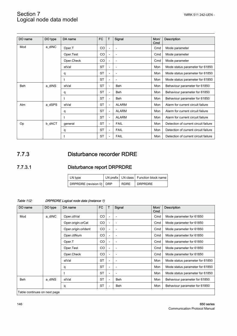
DO name DO type DA name FC T Signal Mon/Cmd
Description
Mod a_dINC Oper.T CO - - Cmd Mode parameter
Oper.Test CO - - Cmd Mode parameter
Oper.Check CO - - Cmd Mode parameter
stVal ST - - Mon Mode status parameter for 61850
q ST - - Mon Mode status parameter for 61850
t ST - - Mon Mode status parameter for 61850
Beh a_dINS stVal ST - Beh Mon Behaviour parameter for 61850
q ST - Beh Mon Behaviour parameter for 61850
t ST - Beh Mon Behaviour parameter for 61850
Alm a_dSPS stVal ST - ALARM Mon Alarm for current circuit failure
q ST - ALARM Mon Alarm for current circuit failure
t ST - ALARM Mon Alarm for current circuit failure
Op b_dACT general ST - FAIL Mon Detection of current circuit failure
q ST - FAIL Mon Detection of current circuit failure
t ST - FAIL Mon Detection of current circuit failure
7.7.3 Disturbance recorder RDRE
7.7.3.1 Disturbance report DRPRDRE
LN type LN prefix LN class Function block name
DRPRDRE (revision 0) DRP RDRE DRPRDRE
Table 112: DRPRDRE Logical node data (instance 1)
DO name DO type DA name FC T Signal Mon/Cmd
Description
Mod a_dINC Oper.ctlVal CO - - Cmd Mode parameter for 61850
Oper.origin.orCat CO - - Cmd Mode parameter for 61850
Oper.origin.orIdent CO - - Cmd Mode parameter for 61850
Oper.ctlNum CO - - Cmd Mode parameter for 61850
Oper.T CO - - Cmd Mode parameter for 61850
Oper.Test CO - - Cmd Mode parameter for 61850
Oper.Check CO - - Cmd Mode parameter for 61850
stVal ST - - Mon Mode status parameter for 61850
q ST - - Mon Mode status parameter for 61850
t ST - - Mon Mode status parameter for 61850
Beh a_dINS stVal ST - Beh Mon Behaviour parameter for 61850
q ST - Beh Mon Behaviour parameter for 61850
Table continues on next page
Section 7 1MRK 511 242-UEN -Logical node data model
146 650 seriesCommunication Protocol Manual

DO name DO type DA name FC T Signal Mon/Cmd
Description
Beh a_dINS t ST - Beh Mon Behaviour parameter for 61850
RcdMade a_dSPS stVal ST - RECMADE Mon Disturbance recording made
q ST - RECMADE Mon Disturbance recording made
t ST - RECMADE Mon Disturbance recording made
FltNum b_dINS stVal ST - FaultNumber Mon Disturbance fault number
q ST - FaultNumber Mon Disturbance fault number
t ST - FaultNumber Mon Disturbance fault number
7.7.4 Fault locator RFLO
7.7.4.1 Fault locator LMBRFLO
LN type LN prefix LN class Function block name
LMBRFLO (revision 1) LMB RFLO LMBRFLO
Table 113: LMBRFLO Logical node data (instance 0)
DO name DO type DA name FC T Signal Mon/Cmd
Description
Mod a_dINC Oper.ctlVal CO - - Cmd Mode parameter
Oper.origin.orCat CO - - Cmd Mode parameter
Oper.origin.orIdent CO - - Cmd Mode parameter
Oper.ctlNum CO - - Cmd Mode parameter
Oper.T CO - - Cmd Mode parameter
Oper.Test CO - - Cmd Mode parameter
Oper.Check CO - - Cmd Mode parameter
stVal ST - - Mon Mode status parameter for 61850
q ST - - Mon Mode status parameter for 61850
t ST - - Mon Mode status parameter for 61850
Beh a_dINS stVal ST - Beh Mon Behaviour parameter for 61850
q ST - Beh Mon Behaviour parameter for 61850
t ST - Beh Mon Behaviour parameter for 61850
FltZ b_dCMV cVal.mag.f MX - FLTDISTX Mon Reactive distance to fault
q MX - FLTDISTX Mon Reactive distance to fault
t MX - FLTDISTX Mon Reactive distance to fault
FltDiskm b_dMV mag.f MX - FltDistLngUnit Mon Distance to fault in line length unit
q MX - FltDistLngUnit Mon Distance to fault in line length unit
t MX - FltDistLngUnit Mon Distance to fault in line length unit
FltLoop e_dINS stVal ST - FaultLoop Mon Fault loop
Table continues on next page
1MRK 511 242-UEN - Section 7Logical node data model
650 series 147Communication Protocol Manual

DO name DO type DA name FC T Signal Mon/Cmd
Description
FltLoop e_dINS q ST - FaultLoop Mon Fault loop
t ST - FaultLoop Mon Fault loop
ClcFlt v1_dSPS stVal ST - CALCMADE Mon Fault calculation made
q ST - CALCMADE Mon Fault calculation made
t ST - CALCMADE Mon Fault calculation made
FltDisRl v2_dMV mag.f MX - FaultDistRelat Mon Distance to fault, relative
q MX - FaultDistRelat Mon Distance to fault, relative
t MX - FaultDistRelat Mon Distance to fault, relative
7.7.5 Fuse failure supervision RFUF
7.7.5.1 Fuse failure supervision SDDRFUF
LN type LN prefix LN class Function block name
SDDRFUF (revision 1) SDD RFUF SDDRFUF
Table 114: SDDRFUF Logical node data (instance 0)
DO name DO type DA name FC T Signal Mon/Cmd
Description
Mod a_dINC Oper.ctlVal CO - - Cmd Mode parameter
Oper.origin.orCat CO - - Cmd Mode parameter
Oper.origin.orIdent CO - - Cmd Mode parameter
Oper.ctlNum CO - - Cmd Mode parameter
Oper.T CO - - Cmd Mode parameter
Oper.Test CO - - Cmd Mode parameter
Oper.Check CO - - Cmd Mode parameter
stVal ST - - Mon Mode status parameter for 61850
q ST - - Mon Mode status parameter for 61850
t ST - - Mon Mode status parameter for 61850
Beh a_dINS stVal ST - Beh Mon Behaviour parameter for 61850
q ST - Beh Mon Behaviour parameter for 61850
t ST - Beh Mon Behaviour parameter for 61850
Str b_dACD general ST - BLKU Mon General start of function
q ST - BLKU Mon General start of function
t ST - BLKU Mon General start of function
Str3Ph v2_dACD general ST - 3PH Mon Three-phase start of function
q ST - 3PH Mon Three-phase start of function
t ST - 3PH Mon Three-phase start of function
Table continues on next page
Section 7 1MRK 511 242-UEN -Logical node data model
148 650 seriesCommunication Protocol Manual

DO name DO type DA name FC T Signal Mon/Cmd
Description
StrRst v2_dACD general ST - BLKZ Mon Start of current and voltagecontrolled function
q ST - BLKZ Mon Start of current and voltagecontrolled function
t ST - BLKZ Mon Start of current and voltagecontrolled function
7.7.6 Pole discordance protection RPLD
7.7.6.1 Pole discordance protection CCRPLD
LN type LN prefix LN class Function block name
CCRPLD (revision 1) CC RPLD CCRPLD
Table 115: CCRPLD Logical node data (instance 0)
DO name DO type DA name FC T Signal Mon/Cmd
Description
Mod a_dINC Oper.ctlVal CO - - Cmd Mode parameter
Oper.origin.orCat CO - - Cmd Mode parameter
Oper.origin.orIdent CO - - Cmd Mode parameter
Oper.ctlNum CO - - Cmd Mode parameter
Oper.T CO - - Cmd Mode parameter
Oper.Test CO - - Cmd Mode parameter
Oper.Check CO - - Cmd Mode parameter
stVal ST - - Mon Mode status parameter for 61850
q ST - - Mon Mode status parameter for 61850
t ST - - Mon Mode status parameter for 61850
Beh a_dINS stVal ST - Beh Mon Behaviour parameter for 61850
q ST - Beh Mon Behaviour parameter for 61850
t ST - Beh Mon Behaviour parameter for 61850
Str b_dACD general ST - START Mon Trip condition TRUE, waiting fortime delay
q ST - START Mon Trip condition TRUE, waiting fortime delay
t ST - START Mon Trip condition TRUE, waiting fortime delay
Op b_dACT general ST T TRIP Mon Trip signal to CB
q ST T TRIP Mon Trip signal to CB
t ST T TRIP Mon Trip signal to CB
1MRK 511 242-UEN - Section 7Logical node data model
650 series 149Communication Protocol Manual

7.7.7 Power swing detection RPSB
7.7.7.1 Power swing detection ZMRPSB
LN type LN prefix LN class Function block name
ZMRPSB (revision 2) ZM RPSB ZMRPSB
Table 116: ZMRPSB Logical node data (instance 1)
DO name DO type DA name FC T Signal Mon/Cmd
Description
Mod a_dINC Oper.ctlVal CO - - Cmd Mode parameter
Oper.origin.orCat CO - - Cmd Mode parameter
Oper.origin.orIdent CO - - Cmd Mode parameter
Oper.ctlNum CO - - Cmd Mode parameter
Oper.T CO - - Cmd Mode parameter
Oper.Test CO - - Cmd Mode parameter
Oper.Check CO - - Cmd Mode parameter
stVal ST - - Mon Mode status parameter for 61850
q ST - - Mon Mode status parameter for 61850
t ST - - Mon Mode status parameter for 61850
Beh a_dINS stVal ST - Beh Mon Behaviour parameter for 61850
q ST - Beh Mon Behaviour parameter for 61850
t ST - Beh Mon Behaviour parameter for 61850
BlkZn a_dSPS stVal ST - START Mon Power swing detected
q ST - START Mon Power swing detected
t ST - START Mon Power swing detected
Str b_dACD general ST - START Mon Power swing detected
q ST - START Mon Power swing detected
t ST - START Mon Power swing detected
ZOuter v1_dSPS stVal ST - ZOUT Mon Measured impedance within outerimpedance boundary
q ST - ZOUT Mon Measured impedance within outerimpedance boundary
t ST - ZOUT Mon Measured impedance within outerimpedance boundary
ZInner v1_dSPS stVal ST - ZIN Mon Measured impedance within innerimpedance boundary
q ST - ZIN Mon Measured impedance within innerimpedance boundary
t ST - ZIN Mon Measured impedance within innerimpedance boundary
Section 7 1MRK 511 242-UEN -Logical node data model
150 650 seriesCommunication Protocol Manual

7.7.8 Autoreclosing RREC
7.7.8.1 Autorecloser SMBRREC
LN type LN prefix LN class Function block name
SMBRREC (revision 2) SMB RREC SMBRREC
Table 117: SMBRREC Logical node data (instance 0)
DO name DO type DA name FC T Signal Mon/Cmd
Description
Mod a_dINC Oper.ctlVal CO - - Cmd Mode parameter
Oper.origin.orCat CO - - Cmd Mode parameter
Oper.origin.orIdent CO - - Cmd Mode parameter
Oper.ctlNum CO - - Cmd Mode parameter
Oper.T CO - - Cmd Mode parameter
Oper.Test CO - - Cmd Mode parameter
Oper.Check CO - - Cmd Mode parameter
stVal ST - - Mon Mode status parameter for 61850
q ST - - Mon Mode status parameter for 61850
t ST - - Mon Mode status parameter for 61850
Beh a_dINS stVal ST - Beh Mon Behaviour parameter for 61850
q ST - Beh Mon Behaviour parameter for 61850
t ST - Beh Mon Behaviour parameter for 61850
Op b_dACT general ST T CLOSECB Mon Closing command for CB
q ST T CLOSECB Mon Closing command for CB
t ST T CLOSECB Mon Closing command for CB
BlkRec c_dSPC stVal ST - BLOCKED Mon AR is in blocked state
q ST - BLOCKED Mon AR is in blocked state
t ST - BLOCKED Mon AR is in blocked state
AutoRecSt d_dINS stVal ST - - Mon AR status; 1=Ready;2=InProgress; 3=Successful
q ST - - Mon AR status; 1=Ready;2=InProgress; 3=Successful
t ST - - Mon AR status; 1=Ready;2=InProgress; 3=Successful
Rec31Cnt v1_dINS stVal ST - COUNT3P1 Mon Counting the number of three-phase reclosing shot 1
q ST - COUNT3P1 Mon Counting the number of three-phase reclosing shot 1
t ST - COUNT3P1 Mon Counting the number of three-phase reclosing shot 1
Rec32Cnt v1_dINS stVal ST - COUNT3P2 Mon Counting the number of three-phase reclosing shot 2
Table continues on next page
1MRK 511 242-UEN - Section 7Logical node data model
650 series 151Communication Protocol Manual

DO name DO type DA name FC T Signal Mon/Cmd
Description
Rec32Cnt v1_dINS q ST - COUNT3P2 Mon Counting the number of three-phase reclosing shot 2
t ST - COUNT3P2 Mon Counting the number of three-phase reclosing shot 2
Rec33Cnt v1_dINS stVal ST - COUNT3P3 Mon Counting the number of three-phase reclosing shot 3
q ST - COUNT3P3 Mon Counting the number of three-phase reclosing shot 3
t ST - COUNT3P3 Mon Counting the number of three-phase reclosing shot 3
Rec34Cnt v1_dINS stVal ST - COUNT3P4 Mon Counting the number of three-phase reclosing shot 4
q ST - COUNT3P4 Mon Counting the number of three-phase reclosing shot 4
t ST - COUNT3P4 Mon Counting the number of three-phase reclosing shot 4
Rec35Cnt v1_dINS stVal ST - COUNT3P5 Mon Counting the number of three-phase reclosing shot 5
q ST - COUNT3P5 Mon Counting the number of three-phase reclosing shot 5
t ST - COUNT3P5 Mon Counting the number of three-phase reclosing shot 5
TotRecCnt v1_dINS stVal ST - COUNTAR Mon Counting total number ofreclosing shots
q ST - COUNTAR Mon Counting total number ofreclosing shots
t ST - COUNTAR Mon Counting total number ofreclosing shots
OpRs v1_dSPC Oper.ctlVal CO - - Cmd Command parameter forIEC61850
Oper.origin.orCat CO - - Cmd Command parameter forIEC61850
Oper.origin.orIdent CO - - Cmd Command parameter forIEC61850
Oper.ctlNum CO - - Cmd Command parameter forIEC61850
Oper.T CO - - Cmd Command parameter forIEC61850
Oper.Test CO - - Cmd Command parameter forIEC61850
Oper.Check CO - - Cmd Command parameter forIEC61850
EnaRec v1_dSPS stVal ST - SETON Mon AR operation is switched on
q ST - SETON Mon AR operation is switched on
t ST - SETON Mon AR operation is switched on
RdyRec v1_dSPS stVal ST - READY Mon Indicates that AR is ready for anew sequence
Table continues on next page
Section 7 1MRK 511 242-UEN -Logical node data model
152 650 seriesCommunication Protocol Manual

DO name DO type DA name FC T Signal Mon/Cmd
Description
RdyRec v1_dSPS q ST - READY Mon Indicates that AR is ready for anew sequence
t ST - READY Mon Indicates that AR is ready for anew sequence
ActRec v1_dSPS stVal ST - ACTIVE Mon Reclosing sequence in progress
q ST - ACTIVE Mon Reclosing sequence in progress
t ST - ACTIVE Mon Reclosing sequence in progress
SucRec v1_dSPS stVal ST - SUCCL Mon Activated if CB closes during thetime tUnsucCl
q ST - SUCCL Mon Activated if CB closes during thetime tUnsucCl
t ST - SUCCL Mon Activated if CB closes during thetime tUnsucCl
UnsRec v1_dSPS stVal ST - UNSUCCL Mon Reclosing unsuccessful, signalresets after the reclaim time
q ST - UNSUCCL Mon Reclosing unsuccessful, signalresets after the reclaim time
t ST - UNSUCCL Mon Reclosing unsuccessful, signalresets after the reclaim time
PrgRec v1_dSPS stVal ST - INPROGR Mon Reclosing shot in progress,activated during open time
q ST - INPROGR Mon Reclosing shot in progress,activated during open time
t ST - INPROGR Mon Reclosing shot in progress,activated during open time
PrgRec31 v1_dSPS stVal ST - 3PT1 Mon Three-phase reclosing inprogress, shot 1
q ST - 3PT1 Mon Three-phase reclosing inprogress, shot 1
t ST - 3PT1 Mon Three-phase reclosing inprogress, shot 1
PrgRec32 v1_dSPS stVal ST - 3PT2 Mon Three-phase reclosing inprogress, shot 2
q ST - 3PT2 Mon Three-phase reclosing inprogress, shot 2
t ST - 3PT2 Mon Three-phase reclosing inprogress, shot 2
PrgRec33 v1_dSPS stVal ST - 3PT3 Mon Three-phase reclosing inprogress, shot 3
q ST - 3PT3 Mon Three-phase reclosing inprogress, shot 3
t ST - 3PT3 Mon Three-phase reclosing inprogress, shot 3
PrgRec34 v1_dSPS stVal ST - 3PT4 Mon Three-phase reclosing inprogress, shot 4
q ST - 3PT4 Mon Three-phase reclosing inprogress, shot 4
Table continues on next page
1MRK 511 242-UEN - Section 7Logical node data model
650 series 153Communication Protocol Manual

DO name DO type DA name FC T Signal Mon/Cmd
Description
PrgRec34 v1_dSPS t ST - 3PT4 Mon Three-phase reclosing inprogress, shot 4
PrgRec35 v1_dSPS stVal ST - 3PT5 Mon Three-phase reclosing inprogress, shot 5
q ST - 3PT5 Mon Three-phase reclosing inprogress, shot 5
t ST - 3PT5 Mon Three-phase reclosing inprogress, shot 5
WtMst v1_dSPS stVal ST - WFMASTER Mon Signal to Slave issued by Masterfor sequential reclosing
q ST - WFMASTER Mon Signal to Slave issued by Masterfor sequential reclosing
t ST - WFMASTER Mon Signal to Slave issued by Masterfor sequential reclosing
7.7.8.2 Autorecloser STBRREC
LN type LN prefix LN class Function block name
STBRREC (revision 0) STB RREC STBRREC
Table 118: STBRREC Logical node data (instance 0)
DO name DO type DA name FC T Signal Mon/Cmd
Description
Mod a_dINC Oper.ctlVal CO - - Cmd Mode parameter
Oper.origin.orCat CO - - Cmd Mode parameter
Oper.origin.orIdent CO - - Cmd Mode parameter
Oper.ctlNum CO - - Cmd Mode parameter
Oper.T CO - - Cmd Mode parameter
Oper.Test CO - - Cmd Mode parameter
Oper.Check CO - - Cmd Mode parameter
stVal ST - - Mon Mode status parameter for 61850
q ST - - Mon Mode status parameter for 61850
t ST - - Mon Mode status parameter for 61850
Beh a_dINS stVal ST - Beh Mon Behaviour parameter for 61850
q ST - Beh Mon Behaviour parameter for 61850
t ST - Beh Mon Behaviour parameter for 61850
Op b_dACT general ST T CLOSECB Mon Closing command for CB
q ST T CLOSECB Mon Closing command for CB
t ST T CLOSECB Mon Closing command for CB
BlkRec c_dSPC stVal ST - BLOCKED Mon AR is in blocked state
q ST - BLOCKED Mon AR is in blocked state
Table continues on next page
Section 7 1MRK 511 242-UEN -Logical node data model
154 650 seriesCommunication Protocol Manual

DO name DO type DA name FC T Signal Mon/Cmd
Description
BlkRec c_dSPC t ST - BLOCKED Mon AR is in blocked state
AutoRecSt d_dINS stVal ST - - Mon AR status; 1=Ready;2=InProgress; 3=Successful
q ST - - Mon AR status; 1=Ready;2=InProgress; 3=Successful
t ST - - Mon AR status; 1=Ready;2=InProgress; 3=Successful
Rec31Cnt v1_dINS stVal ST - COUNT3P1 Mon Counting the number of three-phase reclosing shot 1
q ST - COUNT3P1 Mon Counting the number of three-phase reclosing shot 1
t ST - COUNT3P1 Mon Counting the number of three-phase reclosing shot 1
Rec32Cnt v1_dINS stVal ST - COUNT3P2 Mon Counting the number of three-phase reclosing shot 2
q ST - COUNT3P2 Mon Counting the number of three-phase reclosing shot 2
t ST - COUNT3P2 Mon Counting the number of three-phase reclosing shot 2
Rec33Cnt v1_dINS stVal ST - COUNT3P3 Mon Counting the number of three-phase reclosing shot 3
q ST - COUNT3P3 Mon Counting the number of three-phase reclosing shot 3
t ST - COUNT3P3 Mon Counting the number of three-phase reclosing shot 3
Rec34Cnt v1_dINS stVal ST - COUNT3P4 Mon Counting the number of three-phase reclosing shot 4
q ST - COUNT3P4 Mon Counting the number of three-phase reclosing shot 4
t ST - COUNT3P4 Mon Counting the number of three-phase reclosing shot 4
Rec35Cnt v1_dINS stVal ST - COUNT3P5 Mon Counting the number of three-phase reclosing shot 5
q ST - COUNT3P5 Mon Counting the number of three-phase reclosing shot 5
t ST - COUNT3P5 Mon Counting the number of three-phase reclosing shot 5
TotRecCnt v1_dINS stVal ST - COUNTAR Mon Counting total number ofreclosing shots
q ST - COUNTAR Mon Counting total number ofreclosing shots
t ST - COUNTAR Mon Counting total number ofreclosing shots
Rec1PhCnt v1_dINS stVal ST - COUNT1P Mon Counting the number of single-phase reclosing shots
q ST - COUNT1P Mon Counting the number of single-phase reclosing shots
Table continues on next page
1MRK 511 242-UEN - Section 7Logical node data model
650 series 155Communication Protocol Manual

DO name DO type DA name FC T Signal Mon/Cmd
Description
Rec1PhCnt v1_dINS t ST - COUNT1P Mon Counting the number of single-phase reclosing shots
OpRs v1_dSPC Oper.ctlVal CO - - Cmd Command parameter forIEC61850
Oper.origin.orCat CO - - Cmd Command parameter forIEC61850
Oper.origin.orIdent CO - - Cmd Command parameter forIEC61850
Oper.ctlNum CO - - Cmd Command parameter forIEC61850
Oper.T CO - - Cmd Command parameter forIEC61850
Oper.Test CO - - Cmd Command parameter forIEC61850
Oper.Check CO - - Cmd Command parameter forIEC61850
EnaRec v1_dSPS stVal ST - SETON Mon AR operation is switched on
q ST - SETON Mon AR operation is switched on
t ST - SETON Mon AR operation is switched on
RdyRec v1_dSPS stVal ST - READY Mon Indicates that AR is ready for anew sequence
q ST - READY Mon Indicates that AR is ready for anew sequence
t ST - READY Mon Indicates that AR is ready for anew sequence
ActRec v1_dSPS stVal ST - ACTIVE Mon Reclosing sequence in progress
q ST - ACTIVE Mon Reclosing sequence in progress
t ST - ACTIVE Mon Reclosing sequence in progress
SucRec v1_dSPS stVal ST - SUCCL Mon Activated if CB closes during thetime tUnsucCl
q ST - SUCCL Mon Activated if CB closes during thetime tUnsucCl
t ST - SUCCL Mon Activated if CB closes during thetime tUnsucCl
UnsRec v1_dSPS stVal ST - UNSUCCL Mon Reclosing unsuccessful, signalresets after the reclaim time
q ST - UNSUCCL Mon Reclosing unsuccessful, signalresets after the reclaim time
t ST - UNSUCCL Mon Reclosing unsuccessful, signalresets after the reclaim time
PrgRec v1_dSPS stVal ST - INPROGR Mon Reclosing shot in progress,activated during open time
q ST - INPROGR Mon Reclosing shot in progress,activated during open time
t ST - INPROGR Mon Reclosing shot in progress,activated during open time
Table continues on next page
Section 7 1MRK 511 242-UEN -Logical node data model
156 650 seriesCommunication Protocol Manual
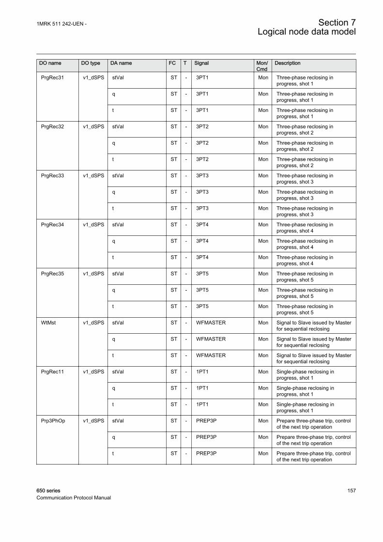
DO name DO type DA name FC T Signal Mon/Cmd
Description
PrgRec31 v1_dSPS stVal ST - 3PT1 Mon Three-phase reclosing inprogress, shot 1
q ST - 3PT1 Mon Three-phase reclosing inprogress, shot 1
t ST - 3PT1 Mon Three-phase reclosing inprogress, shot 1
PrgRec32 v1_dSPS stVal ST - 3PT2 Mon Three-phase reclosing inprogress, shot 2
q ST - 3PT2 Mon Three-phase reclosing inprogress, shot 2
t ST - 3PT2 Mon Three-phase reclosing inprogress, shot 2
PrgRec33 v1_dSPS stVal ST - 3PT3 Mon Three-phase reclosing inprogress, shot 3
q ST - 3PT3 Mon Three-phase reclosing inprogress, shot 3
t ST - 3PT3 Mon Three-phase reclosing inprogress, shot 3
PrgRec34 v1_dSPS stVal ST - 3PT4 Mon Three-phase reclosing inprogress, shot 4
q ST - 3PT4 Mon Three-phase reclosing inprogress, shot 4
t ST - 3PT4 Mon Three-phase reclosing inprogress, shot 4
PrgRec35 v1_dSPS stVal ST - 3PT5 Mon Three-phase reclosing inprogress, shot 5
q ST - 3PT5 Mon Three-phase reclosing inprogress, shot 5
t ST - 3PT5 Mon Three-phase reclosing inprogress, shot 5
WtMst v1_dSPS stVal ST - WFMASTER Mon Signal to Slave issued by Masterfor sequential reclosing
q ST - WFMASTER Mon Signal to Slave issued by Masterfor sequential reclosing
t ST - WFMASTER Mon Signal to Slave issued by Masterfor sequential reclosing
PrgRec11 v1_dSPS stVal ST - 1PT1 Mon Single-phase reclosing inprogress, shot 1
q ST - 1PT1 Mon Single-phase reclosing inprogress, shot 1
t ST - 1PT1 Mon Single-phase reclosing inprogress, shot 1
Prp3PhOp v1_dSPS stVal ST - PREP3P Mon Prepare three-phase trip, controlof the next trip operation
q ST - PREP3P Mon Prepare three-phase trip, controlof the next trip operation
t ST - PREP3P Mon Prepare three-phase trip, controlof the next trip operation
1MRK 511 242-UEN - Section 7Logical node data model
650 series 157Communication Protocol Manual

7.7.9 Synchronising RSYN
7.7.9.1 Synchrocheck, energizing check, and synchronizing SESRSYN
LN type LN prefix LN class Function block name
AUT1RSYN instance 1 (revision 1) AUT1 RSYN SESRSYN
MAN1RSYN instance 2 (revision 1) MAN1 RSYN SESRSYN
RSY1LLN0 instance 1 (revision 1) - LLN0 SESRSYN
SYNRSYN instance 3 (revision 4) SYN RSYN SESRSYN
Table 119: AUT1RSYN Logical node data (instance 1)
DO name DO type DA name FC T Signal Mon/Cmd
Description
Beh a_dINS stVal ST - Beh Mon Behaviour parameter for 61850
q ST - Beh Mon Behaviour parameter for 61850
t ST - Beh Mon Behaviour parameter for 61850
Rel a_dSPS stVal ST - - Mon Automatic release
q ST - - Mon Automatic release
t ST - - Mon Automatic release
AngInd a_dSPS stVal ST - PHDIFFA Mon Phase angle difference out oflimit for Auto operation
q ST - PHDIFFA Mon Phase angle difference out oflimit for Auto operation
t ST - PHDIFFA Mon Phase angle difference out oflimit for Auto operation
HzInd a_dSPS stVal ST - FRDIFFA Mon Frequency difference out of limitfor Auto operation
q ST - FRDIFFA Mon Frequency difference out of limitfor Auto operation
t ST - FRDIFFA Mon Frequency difference out of limitfor Auto operation
DifAngClc b_dMV mag.f MX - PHDIFFME Mon Calculated difference of phaseangle
q MX - PHDIFFME Mon Calculated difference of phaseangle
t MX - PHDIFFME Mon Calculated difference of phaseangle
DifHzClc b_dMV mag.f MX - FRDIFFME Mon Calculated difference in frequency
q MX - FRDIFFME Mon Calculated difference in frequency
t MX - FRDIFFME Mon Calculated difference in frequency
DifVClc b_dMV mag.f MX - UDIFFME Mon Calculated difference in voltage
q MX - UDIFFME Mon Calculated difference in voltage
t MX - UDIFFME Mon Calculated difference in voltage
Mod c_dINC stVal ST - - Mon Mode status parameter for 61850
Table continues on next page
Section 7 1MRK 511 242-UEN -Logical node data model
158 650 seriesCommunication Protocol Manual

DO name DO type DA name FC T Signal Mon/Cmd
Description
Mod c_dINC q ST - - Mon Mode status parameter for 61850
t ST - - Mon Mode status parameter for 61850
EnOK v1_dSPS stVal ST - AUTOENOK Mon Automatic energizing check OK
q ST - AUTOENOK Mon Automatic energizing check OK
t ST - AUTOENOK Mon Automatic energizing check OK
TestSCOK v1_dSPS stVal ST - TSTAUTSY Mon Auto synchro check OK test output
q ST - TSTAUTSY Mon Auto synchro check OK test output
t ST - TSTAUTSY Mon Auto synchro check OK test output
Table 120: MAN1RSYN Logical node data (instance 2)
DO name DO type DA name FC T Signal Mon/Cmd
Description
Beh a_dINS stVal ST - Beh Mon Behaviour parameter for 61850
q ST - Beh Mon Behaviour parameter for 61850
t ST - Beh Mon Behaviour parameter for 61850
Rel a_dSPS stVal ST - - Mon Manual release
q ST - - Mon Manual release
t ST - - Mon Manual release
AngInd a_dSPS stVal ST - PHDIFFM Mon Phase angle difference out oflimit for Manual Operation
q ST - PHDIFFM Mon Phase angle difference out oflimit for Manual Operation
t ST - PHDIFFM Mon Phase angle difference out oflimit for Manual Operation
HzInd a_dSPS stVal ST - FRDIFFM Mon Frequency difference out of limitfor Manual operation
q ST - FRDIFFM Mon Frequency difference out of limitfor Manual operation
t ST - FRDIFFM Mon Frequency difference out of limitfor Manual operation
Mod c_dINC stVal ST - - Mon Mode status parameter for 61850
q ST - - Mon Mode status parameter for 61850
t ST - - Mon Mode status parameter for 61850
EnOK v1_dSPS stVal ST - MANENOK Mon Manual energizing check OK
q ST - MANENOK Mon Manual energizing check OK
t ST - MANENOK Mon Manual energizing check OK
TestSCOK v1_dSPS stVal ST - TSTMANSY Mon Manual synchro check OK testoutput
q ST - TSTMANSY Mon Manual synchro check OK testoutput
t ST - TSTMANSY Mon Manual synchro check OK testoutput
1MRK 511 242-UEN - Section 7Logical node data model
650 series 159Communication Protocol Manual
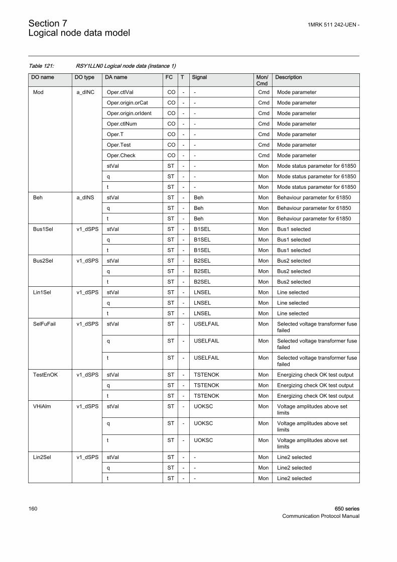
Table 121: RSY1LLN0 Logical node data (instance 1)
DO name DO type DA name FC T Signal Mon/Cmd
Description
Mod a_dINC Oper.ctlVal CO - - Cmd Mode parameter
Oper.origin.orCat CO - - Cmd Mode parameter
Oper.origin.orIdent CO - - Cmd Mode parameter
Oper.ctlNum CO - - Cmd Mode parameter
Oper.T CO - - Cmd Mode parameter
Oper.Test CO - - Cmd Mode parameter
Oper.Check CO - - Cmd Mode parameter
stVal ST - - Mon Mode status parameter for 61850
q ST - - Mon Mode status parameter for 61850
t ST - - Mon Mode status parameter for 61850
Beh a_dINS stVal ST - Beh Mon Behaviour parameter for 61850
q ST - Beh Mon Behaviour parameter for 61850
t ST - Beh Mon Behaviour parameter for 61850
Bus1Sel v1_dSPS stVal ST - B1SEL Mon Bus1 selected
q ST - B1SEL Mon Bus1 selected
t ST - B1SEL Mon Bus1 selected
Bus2Sel v1_dSPS stVal ST - B2SEL Mon Bus2 selected
q ST - B2SEL Mon Bus2 selected
t ST - B2SEL Mon Bus2 selected
Lin1Sel v1_dSPS stVal ST - LNSEL Mon Line selected
q ST - LNSEL Mon Line selected
t ST - LNSEL Mon Line selected
SelFuFail v1_dSPS stVal ST - USELFAIL Mon Selected voltage transformer fusefailed
q ST - USELFAIL Mon Selected voltage transformer fusefailed
t ST - USELFAIL Mon Selected voltage transformer fusefailed
TestEnOK v1_dSPS stVal ST - TSTENOK Mon Energizing check OK test output
q ST - TSTENOK Mon Energizing check OK test output
t ST - TSTENOK Mon Energizing check OK test output
VHiAlm v1_dSPS stVal ST - UOKSC Mon Voltage amplitudes above setlimits
q ST - UOKSC Mon Voltage amplitudes above setlimits
t ST - UOKSC Mon Voltage amplitudes above setlimits
Lin2Sel v1_dSPS stVal ST - - Mon Line2 selected
q ST - - Mon Line2 selected
t ST - - Mon Line2 selected
Section 7 1MRK 511 242-UEN -Logical node data model
160 650 seriesCommunication Protocol Manual

Table 122: SYNRSYN Logical node data (instance 3)
DO name DO type DA name FC T Signal Mon/Cmd
Description
Beh a_dINS stVal ST - Beh Mon Behaviour parameter for 61850
q ST - Beh Mon Behaviour parameter for 61850
t ST - Beh Mon Behaviour parameter for 61850
Rel a_dSPS stVal ST - SYNOK Mon Synchronizing OK output
q ST - SYNOK Mon Synchronizing OK output
t ST - SYNOK Mon Synchronizing OK output
SynPrg a_dSPS stVal ST - SYNPROGR Mon Synchronizing in progress
q ST - SYNPROGR Mon Synchronizing in progress
t ST - SYNPROGR Mon Synchronizing in progress
Mod c_dINC stVal ST - - Mon Mode status parameter for 61850
q ST - - Mon Mode status parameter for 61850
t ST - - Mon Mode status parameter for 61850
FailSyn v1_dSPS stVal ST - SYNFAIL Mon Synchronizing failed
q ST - SYNFAIL Mon Synchronizing failed
t ST - SYNFAIL Mon Synchronizing failed
TestSynOK v1_dSPS stVal ST - TSTSYNOK Mon Synchronizing OK test output
q ST - TSTSYNOK Mon Synchronizing OK test output
t ST - TSTSYNOK Mon Synchronizing OK test output
HzIndSyn v1_dSPS stVal ST - FRDIFSYN Mon Frequency difference out of limitfor synchronizing
q ST - FRDIFSYN Mon Frequency difference out of limitfor synchronizing
t ST - FRDIFSYN Mon Frequency difference out of limitfor synchronizing
HzRCIndSyn v1_dSPS stVal ST - FRDERIVA Mon Frequency derivative out of limitfor synchronizing
q ST - FRDERIVA Mon Frequency derivative out of limitfor synchronizing
t ST - FRDERIVA Mon Frequency derivative out of limitfor synchronizing
7.8 Logical nodes for generic references
7.8.1 Generic process I/O GGIO
7.8.1.1 Apparatus control SELGGIO
LN type LN prefix LN class Function block name
SELGGIO (revision 1) SEL GGIO SELGGIO
1MRK 511 242-UEN - Section 7Logical node data model
650 series 161Communication Protocol Manual

Table 123: SELGGIO Logical node data (instance 1)
DO name DO type DA name FC T Signal Mon/Cmd
Description
Mod a_dINC Oper.ctlVal CO - - Cmd Mode parameter for 61850
Oper.origin.orCat CO - - Cmd Mode parameter for 61850
Oper.origin.orIdent CO - - Cmd Mode parameter for 61850
Oper.ctlNum CO - - Cmd Mode parameter for 61850
Oper.T CO - - Cmd Mode parameter for 61850
Oper.Test CO - - Cmd Mode parameter for 61850
Oper.Check CO - - Cmd Mode parameter for 61850
stVal ST - - Mon Mode status parameter for 61850
q ST - - Mon Mode status parameter for 61850
t ST - - Mon Mode status parameter for 61850
Beh a_dINS stVal ST - Beh Mon Behaviour parameter for 61850
q ST - Beh Mon Behaviour parameter for 61850
t ST - Beh Mon Behaviour parameter for 61850
Rel a_dSPS stVal ST - RESERVED Mon Reserved indication from bay/apparatus
q ST - RESERVED Mon Reserved indication from bay/apparatus
t ST - RESERVED Mon Reserved indication from bay/apparatus
7.8.1.2 Logic Rotating Switch for function selection and LHMI presentationSLGGIO
LN type LN prefix LN class Function block name
SLGGIO (revision 2) SL GGIO SLGGIO
Table 124: SLGGIO Logical node data (instance 1)
DO name DO type DA name FC T Signal Mon/Cmd
Description
Mod a_dINC Oper.ctlVal CO - - Cmd Mode parameter
Oper.origin.orCat CO - - Cmd Mode parameter
Oper.origin.orIdent CO - - Cmd Mode parameter
Oper.ctlNum CO - - Cmd Mode parameter
Oper.T CO - - Cmd Mode parameter
Oper.Test CO - - Cmd Mode parameter
Oper.Check CO - - Cmd Mode parameter
stVal ST - - Mon Mode status parameter for 61850
q ST - - Mon Mode status parameter for 61850
Table continues on next page
Section 7 1MRK 511 242-UEN -Logical node data model
162 650 seriesCommunication Protocol Manual

DO name DO type DA name FC T Signal Mon/Cmd
Description
Mod a_dINC t ST - - Mon Mode status parameter for 61850
Beh a_dINS stVal ST - Beh Mon Behaviour parameter for 61850
q ST - Beh Mon Behaviour parameter for 61850
t ST - Beh Mon Behaviour parameter for 61850
IntIn b_dINS stVal ST - SWPOSN Mon Switch position as integer value
q ST - SWPOSN Mon Switch position as integer value
t ST - SWPOSN Mon Switch position as integer value
SwPosC1 v1_dISC Oper.ctlVal CO - - Cmd Command parameter forIEC61850
Oper.origin.orCat CO - - Cmd Command parameter forIEC61850
valWTr.posVal ST - - Mon Position
Oper.origin.orIdent CO - - Cmd Command parameter forIEC61850
Oper.ctlNum CO - - Cmd Command parameter forIEC61850
Oper.T CO - - Cmd Command parameter forIEC61850
Oper.Test CO - - Cmd Command parameter forIEC61850
Oper.Check CO - - Cmd Command parameter forIEC61850
q ST - - Mon Position
t ST - - Mon Position
ctlModel CF - - - Used by CH
sboTimeout CF - - - Used by CH
sboClass CF - - - Used by CH
SPCCO v2_dSPC Oper.ctlVal CO - - Cmd Command parameter forIEC61850
Oper.origin.orCat CO - - Cmd Command parameter forIEC61850
Oper.origin.orIdent CO - - Cmd Command parameter forIEC61850
Oper.ctlNum CO - - Cmd Command parameter forIEC61850
Oper.T CO - - Cmd Command parameter forIEC61850
Oper.Test CO - - Cmd Command parameter forIEC61850
Oper.Check CO - - Cmd Command parameter forIEC61850
ctlModel CF - - - Used by CH
sboTimeout CF - - - Used by CH
sboClass CF - - - Used by CH
1MRK 511 242-UEN - Section 7Logical node data model
650 series 163Communication Protocol Manual

7.8.1.3 Selector mini switch VSGGIO
LN type LN prefix LN class Function block name
VSGGIO (revision 1) VS GGIO VSGGIO
Table 125: VSGGIO Logical node data (instance 1)
DO name DO type DA name FC T Signal Mon/Cmd
Description
Mod a_dINC Oper.ctlVal CO - - Cmd Mode parameter
Oper.origin.orCat CO - - Cmd Mode parameter
Oper.origin.orIdent CO - - Cmd Mode parameter
Oper.ctlNum CO - - Cmd Mode parameter
Oper.T CO - - Cmd Mode parameter
Oper.Test CO - - Cmd Mode parameter
Oper.Check CO - - Cmd Mode parameter
stVal ST - - Mon Mode status parameter for 61850
q ST - - Mon Mode status parameter for 61850
t ST - - Mon Mode status parameter for 61850
Beh a_dINS stVal ST - Beh Mon Behaviour parameter for 61850
q ST - Beh Mon Behaviour parameter for 61850
t ST - Beh Mon Behaviour parameter for 61850
DPCSO d_dDPC Cancel.ctlVal CO - - Cmd Command parameter forIEC61850
Cancel.origin.orCat CO - - Cmd Command parameter forIEC61850
Oper.ctlVal CO - - Cmd Command parameter forIEC61850
Oper.origin.orCat CO - - Cmd Command parameter forIEC61850
SBOw.ctlVal CO - - Cmd Command parameter forIEC61850
SBOw.origin.orCat CO - - Cmd Command parameter forIEC61850
SBOw.origin.orIdent CO - - Cmd Command parameter forIEC61850
Oper.origin.orIdent CO - - Cmd Command parameter forIEC61850
Cancel.origin.orIdent CO - - Cmd Command parameter forIEC61850
Cancel.ctlNum CO - - Cmd Command parameter forIEC61850
Oper.ctlNum CO - - Cmd Command parameter forIEC61850
SBOw.ctlNum CO - - Cmd Command parameter forIEC61850
Table continues on next page
Section 7 1MRK 511 242-UEN -Logical node data model
164 650 seriesCommunication Protocol Manual

DO name DO type DA name FC T Signal Mon/Cmd
Description
DPCSO d_dDPC Oper.T CO - - Cmd Command parameter forIEC61850
Cancel.T CO - - Cmd Command parameter forIEC61850
SBOw.T CO - - Cmd Command parameter forIEC61850
SBOw.Test CO - - Cmd Command parameter forIEC61850
Cancel.Test CO - - Cmd Command parameter forIEC61850
Oper.Test CO - - Cmd Command parameter forIEC61850
SBOw.Check CO - - Cmd Command parameter forIEC61850
Oper.Check CO - - Cmd Command parameter forIEC61850
stVal ST - POSITION Mon Position indication, integer
q ST - POSITION Mon Position indication, integer
t ST - POSITION Mon Position indication, integer
stSeld ST - - Mon Used by CH
ctlModel CF - CtlModel - Specifies the type for controlmodel according to IEC 61850
7.8.1.4 IEC61850 generic communication I/O functions DPGGIO
LN type LN prefix LN class Function block name
DPGGIO (revision 1) DP GGIO DPGGIO
Table 126: DPGGIO Logical node data (instance 0)
DO name DO type DA name FC T Signal Mon/Cmd
Description
Mod a_dINC Oper.ctlVal CO - - Cmd Mode parameter
Oper.origin.orCat CO - - Cmd Mode parameter
Oper.origin.orIdent CO - - Cmd Mode parameter
Oper.ctlNum CO - - Cmd Mode parameter
Oper.T CO - - Cmd Mode parameter
Oper.Test CO - - Cmd Mode parameter
Oper.Check CO - - Cmd Mode parameter
stVal ST - - Mon Mode status parameter for 61850
q ST - - Mon Mode status parameter for 61850
t ST - - Mon Mode status parameter for 61850
Beh a_dINS stVal ST - Beh Mon Behaviour parameter for 61850
Table continues on next page
1MRK 511 242-UEN - Section 7Logical node data model
650 series 165Communication Protocol Manual

DO name DO type DA name FC T Signal Mon/Cmd
Description
Beh a_dINS q ST - Beh Mon Behaviour parameter for 61850
t ST - Beh Mon Behaviour parameter for 61850
DPCSO b_dDPC stVal ST - POSITION Mon Double point indication
q ST - POSITION Mon Double point indication
t ST - POSITION Mon Double point indication
7.8.1.5 Single Point Generic Control 8 signals SPC8GGIO
LN type LN prefix LN class Function block name
SPC8GGIO (revision 1) SPC8 GGIO SPC8GGIO
Table 127: SPC8GGIO Logical node data (instance 1)
DO name DO type DA name FC T Signal Mon/Cmd
Description
Mod a_dINC Oper.ctlVal CO - - Cmd Mode parameter for 61850
Oper.origin.orCat CO - - Cmd Mode parameter for 61850
Oper.origin.orIdent CO - - Cmd Mode parameter for 61850
Oper.ctlNum CO - - Cmd Mode parameter for 61850
Oper.T CO - - Cmd Mode parameter for 61850
Oper.Test CO - - Cmd Mode parameter for 61850
Oper.Check CO - - Cmd Mode parameter for 61850
stVal ST - - Mon Mode status parameter for 61850
q ST - - Mon Mode status parameter for 61850
t ST - - Mon Mode status parameter for 61850
Beh a_dINS stVal ST - Beh Mon Behaviour parameter for 61850
q ST - Beh Mon Behaviour parameter for 61850
t ST - Beh Mon Behaviour parameter for 61850
SPCSO1 v2_dSPC Oper.ctlVal CO - - Cmd Command parameter forIEC61850
Oper.origin.orCat CO - - Cmd Command parameter forIEC61850
Oper.origin.orIdent CO - - Cmd Command parameter forIEC61850
Oper.ctlNum CO - - Cmd Command parameter forIEC61850
Oper.T CO - - Cmd Command parameter forIEC61850
Oper.Test CO - - Cmd Command parameter forIEC61850
Oper.Check CO - - Cmd Command parameter forIEC61850
Table continues on next page
Section 7 1MRK 511 242-UEN -Logical node data model
166 650 seriesCommunication Protocol Manual

DO name DO type DA name FC T Signal Mon/Cmd
Description
SPCSO1 v2_dSPC stVal ST - OUT1 Mon Output 1
q ST - OUT1 Mon Output 1
t ST - OUT1 Mon Output 1
SPCSO2 v2_dSPC Oper.ctlVal CO - - Cmd Command parameter forIEC61850
Oper.origin.orCat CO - - Cmd Command parameter forIEC61850
Oper.origin.orIdent CO - - Cmd Command parameter forIEC61850
Oper.ctlNum CO - - Cmd Command parameter forIEC61850
Oper.T CO - - Cmd Command parameter forIEC61850
Oper.Test CO - - Cmd Command parameter forIEC61850
Oper.Check CO - - Cmd Command parameter forIEC61850
stVal ST - OUT2 Mon Output2
q ST - OUT2 Mon Output2
t ST - OUT2 Mon Output2
SPCSO3 v2_dSPC Oper.ctlVal CO - - Cmd Command parameter forIEC61850
Oper.origin.orCat CO - - Cmd Command parameter forIEC61850
Oper.origin.orIdent CO - - Cmd Command parameter forIEC61850
Oper.ctlNum CO - - Cmd Command parameter forIEC61850
Oper.T CO - - Cmd Command parameter forIEC61850
Oper.Test CO - - Cmd Command parameter forIEC61850
Oper.Check CO - - Cmd Command parameter forIEC61850
stVal ST - OUT3 Mon Output3
q ST - OUT3 Mon Output3
t ST - OUT3 Mon Output3
SPCSO4 v2_dSPC Oper.ctlVal CO - - Cmd Command parameter forIEC61850
Oper.origin.orCat CO - - Cmd Command parameter forIEC61850
Oper.origin.orIdent CO - - Cmd Command parameter forIEC61850
Oper.ctlNum CO - - Cmd Command parameter forIEC61850
Table continues on next page
1MRK 511 242-UEN - Section 7Logical node data model
650 series 167Communication Protocol Manual

DO name DO type DA name FC T Signal Mon/Cmd
Description
SPCSO4 v2_dSPC Oper.T CO - - Cmd Command parameter forIEC61850
Oper.Test CO - - Cmd Command parameter forIEC61850
Oper.Check CO - - Cmd Command parameter forIEC61850
stVal ST - OUT4 Mon Output4
q ST - OUT4 Mon Output4
t ST - OUT4 Mon Output4
SPCSO5 v2_dSPC Oper.ctlVal CO - - Cmd Command parameter forIEC61850
Oper.origin.orCat CO - - Cmd Command parameter forIEC61850
Oper.origin.orIdent CO - - Cmd Command parameter forIEC61850
Oper.ctlNum CO - - Cmd Command parameter forIEC61850
Oper.T CO - - Cmd Command parameter forIEC61850
Oper.Test CO - - Cmd Command parameter forIEC61850
Oper.Check CO - - Cmd Command parameter forIEC61850
stVal ST - OUT5 Mon Output5
q ST - OUT5 Mon Output5
t ST - OUT5 Mon Output5
SPCSO6 v2_dSPC Oper.ctlVal CO - - Cmd Command parameter forIEC61850
Oper.origin.orCat CO - - Cmd Command parameter forIEC61850
Oper.origin.orIdent CO - - Cmd Command parameter forIEC61850
Oper.ctlNum CO - - Cmd Command parameter forIEC61850
Oper.T CO - - Cmd Command parameter forIEC61850
Oper.Test CO - - Cmd Command parameter forIEC61850
Oper.Check CO - - Cmd Command parameter forIEC61850
stVal ST - OUT6 Mon Output6
q ST - OUT6 Mon Output6
t ST - OUT6 Mon Output6
SPCSO7 v2_dSPC Oper.ctlVal CO - - Cmd Command parameter forIEC61850
Table continues on next page
Section 7 1MRK 511 242-UEN -Logical node data model
168 650 seriesCommunication Protocol Manual

DO name DO type DA name FC T Signal Mon/Cmd
Description
SPCSO7 v2_dSPC Oper.origin.orCat CO - - Cmd Command parameter forIEC61850
Oper.origin.orIdent CO - - Cmd Command parameter forIEC61850
Oper.ctlNum CO - - Cmd Command parameter forIEC61850
Oper.T CO - - Cmd Command parameter forIEC61850
Oper.Test CO - - Cmd Command parameter forIEC61850
Oper.Check CO - - Cmd Command parameter forIEC61850
stVal ST - OUT7 Mon Output7
q ST - OUT7 Mon Output7
t ST - OUT7 Mon Output7
SPCSO8 v2_dSPC Oper.ctlVal CO - - Cmd Command parameter forIEC61850
Oper.origin.orCat CO - - Cmd Command parameter forIEC61850
Oper.origin.orIdent CO - - Cmd Command parameter forIEC61850
Oper.ctlNum CO - - Cmd Command parameter forIEC61850
Oper.T CO - - Cmd Command parameter forIEC61850
Oper.Test CO - - Cmd Command parameter forIEC61850
Oper.Check CO - - Cmd Command parameter forIEC61850
stVal ST - OUT8 Mon Output8
q ST - OUT8 Mon Output8
t ST - OUT8 Mon Output8
7.8.1.6 Event counter CNTGGIO
LN type LN prefix LN class Function block name
CNTGGIO (revision 1) CNT GGIO CNTGGIO
1MRK 511 242-UEN - Section 7Logical node data model
650 series 169Communication Protocol Manual

Table 128: CNTGGIO Logical node data (instance 0)
DO name DO type DA name FC T Signal Mon/Cmd
Description
Mod a_dINC Oper.ctlVal CO - - Cmd Mode parameter for 61850
Oper.origin.orCat CO - - Cmd Mode parameter for 61850
Oper.origin.orIdent CO - - Cmd Mode parameter for 61850
Oper.ctlNum CO - - Cmd Mode parameter for 61850
Oper.T CO - - Cmd Mode parameter for 61850
Oper.Test CO - - Cmd Mode parameter for 61850
Oper.Check CO - - Cmd Mode parameter for 61850
stVal ST - - Mon Mode status parameter for 61850
q ST - - Mon Mode status parameter for 61850
t ST - - Mon Mode status parameter for 61850
Beh a_dINS stVal ST - Beh Mon Behaviour parameter for 61850
q ST - Beh Mon Behaviour parameter for 61850
t ST - Beh Mon Behaviour parameter for 61850
Cnt1 v1_dBCR actVal ST - VALUE1 Mon Output of counter 1
q ST - VALUE1 Mon Output of counter 1
t ST - VALUE1 Mon Output of counter 1
Cnt2 v1_dBCR actVal ST - VALUE2 Mon Output of counter 2
q ST - VALUE2 Mon Output of counter 2
t ST - VALUE2 Mon Output of counter 2
Cnt3 v1_dBCR actVal ST - VALUE3 Mon Output of counter 3
q ST - VALUE3 Mon Output of counter 3
t ST - VALUE3 Mon Output of counter 3
Cnt4 v1_dBCR actVal ST - VALUE4 Mon Output of counter 4
q ST - VALUE4 Mon Output of counter 4
t ST - VALUE4 Mon Output of counter 4
Cnt5 v1_dBCR actVal ST - VALUE5 Mon Output of counter 5
q ST - VALUE5 Mon Output of counter 5
t ST - VALUE5 Mon Output of counter 5
Cnt6 v1_dBCR actVal ST - VALUE6 Mon Output of counter 6
q ST - VALUE6 Mon Output of counter 6
t ST - VALUE6 Mon Output of counter 6
RsCnt v1_dSPC Oper.ctlVal CO - - Cmd Command parameter forIEC61850
Oper.origin.orCat CO - - Cmd Command parameter forIEC61850
Oper.origin.orIdent CO - - Cmd Command parameter forIEC61850
Oper.ctlNum CO - - Cmd Command parameter forIEC61850
Table continues on next page
Section 7 1MRK 511 242-UEN -Logical node data model
170 650 seriesCommunication Protocol Manual

DO name DO type DA name FC T Signal Mon/Cmd
Description
RsCnt v1_dSPC Oper.T CO - - Cmd Command parameter forIEC61850
Oper.Test CO - - Cmd Command parameter forIEC61850
Oper.Check CO - - Cmd Command parameter forIEC61850
7.8.1.7 IEC61850 generic communication I/O functions SPGGIO
LN type LN prefix LN class Function block name
SPGGIO (revision 1) SP GGIO SPGGIO
Table 129: SPGGIO Logical node data (instance 0)
DO name DO type DA name FC T Signal Mon/Cmd
Description
Mod a_dINC Oper.ctlVal CO - - Cmd Mode parameter
Oper.origin.orCat CO - - Cmd Mode parameter
Oper.origin.orIdent CO - - Cmd Mode parameter
Oper.ctlNum CO - - Cmd Mode parameter
Oper.T CO - - Cmd Mode parameter
Oper.Test CO - - Cmd Mode parameter
Oper.Check CO - - Cmd Mode parameter
stVal ST - - Mon Mode status parameter for 61850
q ST - - Mon Mode status parameter for 61850
t ST - - Mon Mode status parameter for 61850
Beh a_dINS stVal ST - Beh Mon Behaviour parameter for 61850
q ST - Beh Mon Behaviour parameter for 61850
t ST - Beh Mon Behaviour parameter for 61850
Ind c_dSPS stVal ST - OUT Mon Output status
q ST - OUT Mon Output status
t ST - OUT Mon Output status
7.8.1.8 IEC61850 generic communication I/O functions 16 inputs SP16GGIO
LN type LN prefix LN class Function block name
SP16GGIO (revision 1) SP16 GGIO SP16GGIO
1MRK 511 242-UEN - Section 7Logical node data model
650 series 171Communication Protocol Manual

Table 130: SP16GGIO Logical node data (instance 1)
DO name DO type DA name FC T Signal Mon/Cmd
Description
Mod a_dINC Oper.ctlVal CO - - Cmd Mode parameter
Oper.origin.orCat CO - - Cmd Mode parameter
Oper.origin.orIdent CO - - Cmd Mode parameter
Oper.ctlNum CO - - Cmd Mode parameter
Oper.T CO - - Cmd Mode parameter
Oper.Test CO - - Cmd Mode parameter
Oper.Check CO - - Cmd Mode parameter
stVal ST - - Mon Mode status parameter for 61850
q ST - - Mon Mode status parameter for 61850
t ST - - Mon Mode status parameter for 61850
Beh a_dINS stVal ST - Beh Mon Behaviour parameter for 61850
q ST - Beh Mon Behaviour parameter for 61850
t ST - Beh Mon Behaviour parameter for 61850
Ind c_dSPS stVal ST - OUT1 Mon Output 1 status
q ST - OUT1 Mon Output 1 status
t ST - OUT1 Mon Output 1 status
Ind2 v1_dSPS stVal ST - OUT2 Mon Output 2 status
q ST - OUT2 Mon Output 2 status
t ST - OUT2 Mon Output 2 status
Ind3 v1_dSPS stVal ST - OUT3 Mon Output 3 status
q ST - OUT3 Mon Output 3 status
t ST - OUT3 Mon Output 3 status
Ind4 v1_dSPS stVal ST - OUT4 Mon Output 4 status
q ST - OUT4 Mon Output 4 status
t ST - OUT4 Mon Output 4 status
Ind5 v1_dSPS stVal ST - OUT5 Mon Output 5 status
q ST - OUT5 Mon Output 5 status
t ST - OUT5 Mon Output 5 status
Ind6 v1_dSPS stVal ST - OUT6 Mon Output 6 status
q ST - OUT6 Mon Output 6 status
t ST - OUT6 Mon Output 6 status
Ind7 v1_dSPS stVal ST - OUT7 Mon Output 7 status
q ST - OUT7 Mon Output 7 status
t ST - OUT7 Mon Output 7 status
Ind8 v1_dSPS stVal ST - OUT8 Mon Output 8 status
q ST - OUT8 Mon Output 8 status
t ST - OUT8 Mon Output 8 status
Ind9 v1_dSPS stVal ST - OUT9 Mon Output 9 status
Table continues on next page
Section 7 1MRK 511 242-UEN -Logical node data model
172 650 seriesCommunication Protocol Manual

DO name DO type DA name FC T Signal Mon/Cmd
Description
Ind9 v1_dSPS q ST - OUT9 Mon Output 9 status
t ST - OUT9 Mon Output 9 status
Ind10 v1_dSPS stVal ST - OUT10 Mon Output 10 status
q ST - OUT10 Mon Output 10 status
t ST - OUT10 Mon Output 10 status
Ind11 v1_dSPS stVal ST - OUT11 Mon Output 11 status
q ST - OUT11 Mon Output 11 status
t ST - OUT11 Mon Output 11 status
Ind12 v1_dSPS stVal ST - OUT12 Mon Output 12 status
q ST - OUT12 Mon Output 12 status
t ST - OUT12 Mon Output 12 status
Ind13 v1_dSPS stVal ST - OUT13 Mon Output 13 status
q ST - OUT13 Mon Output 13 status
t ST - OUT13 Mon Output 13 status
Ind14 v1_dSPS stVal ST - OUT14 Mon Output 14 status
q ST - OUT14 Mon Output 14 status
t ST - OUT14 Mon Output 14 status
Ind15 v1_dSPS stVal ST - OUT15 Mon Output 15 status
q ST - OUT15 Mon Output 15 status
t ST - OUT15 Mon Output 15 status
Ind16 v1_dSPS stVal ST - OUT16 Mon Output 16 status
q ST - OUT16 Mon Output 16 status
t ST - OUT16 Mon Output 16 status
GrInd v1_dSPS stVal ST - OUTOR Mon Output status logic OR gate forinput 1 to 16
q ST - OUTOR Mon Output status logic OR gate forinput 1 to 16
t ST - OUTOR Mon Output status logic OR gate forinput 1 to 16
7.8.1.9 IEC61850 generic communication I/O functions MVGGIO
LN type LN prefix LN class Function block name
MVGGIO (revision 1) MV GGIO MVGGIO
1MRK 511 242-UEN - Section 7Logical node data model
650 series 173Communication Protocol Manual
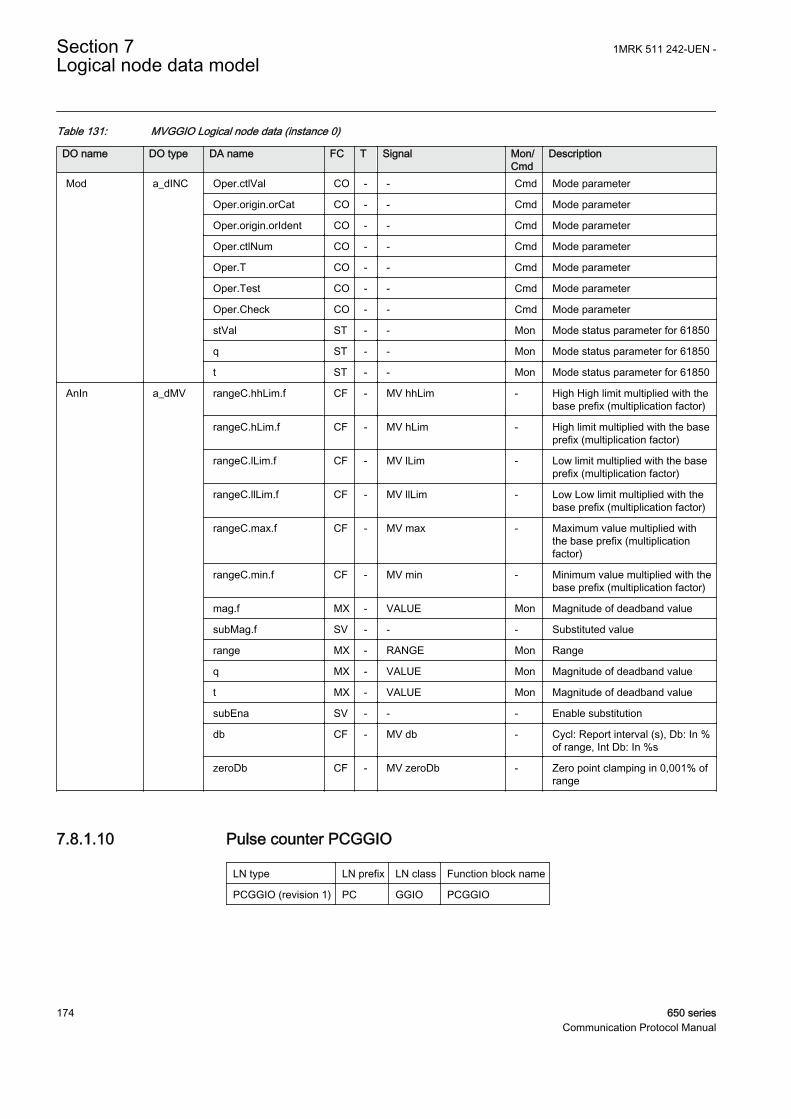
Table 131: MVGGIO Logical node data (instance 0)
DO name DO type DA name FC T Signal Mon/Cmd
Description
Mod a_dINC Oper.ctlVal CO - - Cmd Mode parameter
Oper.origin.orCat CO - - Cmd Mode parameter
Oper.origin.orIdent CO - - Cmd Mode parameter
Oper.ctlNum CO - - Cmd Mode parameter
Oper.T CO - - Cmd Mode parameter
Oper.Test CO - - Cmd Mode parameter
Oper.Check CO - - Cmd Mode parameter
stVal ST - - Mon Mode status parameter for 61850
q ST - - Mon Mode status parameter for 61850
t ST - - Mon Mode status parameter for 61850
AnIn a_dMV rangeC.hhLim.f CF - MV hhLim - High High limit multiplied with thebase prefix (multiplication factor)
rangeC.hLim.f CF - MV hLim - High limit multiplied with the baseprefix (multiplication factor)
rangeC.lLim.f CF - MV lLim - Low limit multiplied with the baseprefix (multiplication factor)
rangeC.llLim.f CF - MV llLim - Low Low limit multiplied with thebase prefix (multiplication factor)
rangeC.max.f CF - MV max - Maximum value multiplied withthe base prefix (multiplicationfactor)
rangeC.min.f CF - MV min - Minimum value multiplied with thebase prefix (multiplication factor)
mag.f MX - VALUE Mon Magnitude of deadband value
subMag.f SV - - - Substituted value
range MX - RANGE Mon Range
q MX - VALUE Mon Magnitude of deadband value
t MX - VALUE Mon Magnitude of deadband value
subEna SV - - - Enable substitution
db CF - MV db - Cycl: Report interval (s), Db: In %of range, Int Db: In %s
zeroDb CF - MV zeroDb - Zero point clamping in 0,001% ofrange
7.8.1.10 Pulse counter PCGGIO
LN type LN prefix LN class Function block name
PCGGIO (revision 1) PC GGIO PCGGIO
Section 7 1MRK 511 242-UEN -Logical node data model
174 650 seriesCommunication Protocol Manual
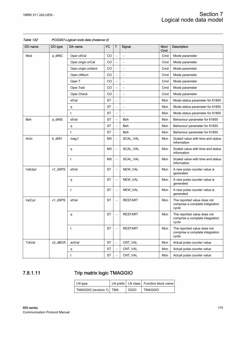
Table 132: PCGGIO Logical node data (instance 0)
DO name DO type DA name FC T Signal Mon/Cmd
Description
Mod a_dINC Oper.ctlVal CO - - Cmd Mode parameter
Oper.origin.orCat CO - - Cmd Mode parameter
Oper.origin.orIdent CO - - Cmd Mode parameter
Oper.ctlNum CO - - Cmd Mode parameter
Oper.T CO - - Cmd Mode parameter
Oper.Test CO - - Cmd Mode parameter
Oper.Check CO - - Cmd Mode parameter
stVal ST - - Mon Mode status parameter for 61850
q ST - - Mon Mode status parameter for 61850
t ST - - Mon Mode status parameter for 61850
Beh a_dINS stVal ST - Beh Mon Behaviour parameter for 61850
q ST - Beh Mon Behaviour parameter for 61850
t ST - Beh Mon Behaviour parameter for 61850
AnIn b_dMV mag.f MX - SCAL_VAL Mon Scaled value with time and statusinformation
q MX - SCAL_VAL Mon Scaled value with time and statusinformation
t MX - SCAL_VAL Mon Scaled value with time and statusinformation
ValUpd v1_dSPS stVal ST - NEW_VAL Mon A new pulse counter value isgenerated
q ST - NEW_VAL Mon A new pulse counter value isgenerated
t ST - NEW_VAL Mon A new pulse counter value isgenerated
IcpCyc v1_dSPS stVal ST - RESTART Mon The reported value does notcomprise a complete integrationcycle
q ST - RESTART Mon The reported value does notcomprise a complete integrationcycle
t ST - RESTART Mon The reported value does notcomprise a complete integrationcycle
TotVal v2_dBCR actVal ST - CNT_VAL Mon Actual pulse counter value
q ST - CNT_VAL Mon Actual pulse counter value
t ST - CNT_VAL Mon Actual pulse counter value
7.8.1.11 Trip matrix logic TMAGGIO
LN type LN prefix LN class Function block name
TMAGGIO (revision 1) TMA GGIO TMAGGIO
1MRK 511 242-UEN - Section 7Logical node data model
650 series 175Communication Protocol Manual

Table 133: TMAGGIO Logical node data (instance 1)
DO name DO type DA name FC T Signal Mon/Cmd
Description
Mod a_dINC Oper.ctlVal CO - - Cmd Mode parameter
Oper.origin.orCat CO - - Cmd Mode parameter
Oper.origin.orIdent CO - - Cmd Mode parameter
Oper.ctlNum CO - - Cmd Mode parameter
Oper.T CO - - Cmd Mode parameter
Oper.Test CO - - Cmd Mode parameter
Oper.Check CO - - Cmd Mode parameter
stVal ST - - Mon Mode status parameter for 61850
q ST - - Mon Mode status parameter for 61850
t ST - - Mon Mode status parameter for 61850
Beh a_dINS stVal ST - Beh Mon Behaviour parameter for 61850
q ST - Beh Mon Behaviour parameter for 61850
t ST - Beh Mon Behaviour parameter for 61850
Out1 v1_dSPS stVal ST - OUTPUT1 Mon OR function betweeen inputs 1 to16
q ST - OUTPUT1 Mon OR function betweeen inputs 1 to16
t ST - OUTPUT1 Mon OR function betweeen inputs 1 to16
Out2 v1_dSPS stVal ST - OUTPUT2 Mon OR function between inputs 17 to32
q ST - OUTPUT2 Mon OR function between inputs 17 to32
t ST - OUTPUT2 Mon OR function between inputs 17 to32
Out3 v1_dSPS stVal ST - OUTPUT3 Mon OR function between inputs 1 to 32
q ST - OUTPUT3 Mon OR function between inputs 1 to 32
t ST - OUTPUT3 Mon OR function between inputs 1 to 32
7.9 Logical nodes for metering and measurement
7.9.1 Metering MMTR
7.9.1.1 Function for energy calculation and demand handling ETPMMTR
LN type LN prefix LN class Function block name
ETPMMTR (revision 1) ETP MMTR ETPMMTR
Section 7 1MRK 511 242-UEN -Logical node data model
176 650 seriesCommunication Protocol Manual

Table 134: ETPMMTR Logical node data (instance 1)
DO name DO type DA name FC T Signal Mon/Cmd
Description
Mod a_dINC Oper.ctlVal CO - - Cmd Mode parameter for 61850
Oper.origin.orCat CO - - Cmd Mode parameter for 61850
Oper.origin.orIdent CO - - Cmd Mode parameter for 61850
Oper.ctlNum CO - - Cmd Mode parameter for 61850
Oper.T CO - - Cmd Mode parameter for 61850
Oper.Test CO - - Cmd Mode parameter for 61850
Oper.Check CO - - Cmd Mode parameter for 61850
stVal ST - - Mon Mode status parameter for 61850
q ST - - Mon Mode status parameter for 61850
t ST - - Mon Mode status parameter for 61850
Beh a_dINS stVal ST - Beh Mon Behaviour parameter for 61850
q ST - Beh Mon Behaviour parameter for 61850
t ST - Beh Mon Behaviour parameter for 61850
SupRs v1_dSPC Oper.ctlVal CO - - Cmd Command parameter forIEC61850
Oper.origin.orCat CO - - Cmd Command parameter forIEC61850
Oper.origin.orIdent CO - - Cmd Command parameter forIEC61850
Oper.ctlNum CO - - Cmd Command parameter forIEC61850
Oper.T CO - - Cmd Command parameter forIEC61850
Oper.Test CO - - Cmd Command parameter forIEC61850
Oper.Check CO - - Cmd Command parameter forIEC61850
MaxDmdRs v1_dSPC Oper.ctlVal CO - - Cmd Command parameter forIEC61850
Oper.origin.orCat CO - - Cmd Command parameter forIEC61850
Oper.origin.orIdent CO - - Cmd Command parameter forIEC61850
Oper.ctlNum CO - - Cmd Command parameter forIEC61850
Oper.T CO - - Cmd Command parameter forIEC61850
Oper.Test CO - - Cmd Command parameter forIEC61850
Oper.Check CO - - Cmd Command parameter forIEC61850
StrAcc v1_dSPS stVal ST - ACCST Mon Start of accumulating energyvalues
Table continues on next page
1MRK 511 242-UEN - Section 7Logical node data model
650 series 177Communication Protocol Manual

DO name DO type DA name FC T Signal Mon/Cmd
Description
StrAcc v1_dSPS q ST - ACCST Mon Start of accumulating energyvalues
t ST - ACCST Mon Start of accumulating energyvalues
WhFwdAlm v1_dSPS stVal ST - EAFALM Mon Alarm for active forward energyexceed limit in set interval
q ST - EAFALM Mon Alarm for active forward energyexceed limit in set interval
t ST - EAFALM Mon Alarm for active forward energyexceed limit in set interval
WhRvAlm v1_dSPS stVal ST - EARALM Mon Alarm for active reverse energyexceed limit in set interval
q ST - EARALM Mon Alarm for active reverse energyexceed limit in set interval
t ST - EARALM Mon Alarm for active reverse energyexceed limit in set interval
VArhFwdAlm v1_dSPS stVal ST - ERFALM Mon Alarm for reactive forward energyexceed limit in set interval
q ST - ERFALM Mon Alarm for reactive forward energyexceed limit in set interval
t ST - ERFALM Mon Alarm for reactive forward energyexceed limit in set interval
VArhRvAlm v1_dSPS stVal ST - ERRALM Mon Alarm for reactive reverse energyexceed limit in set interval
q ST - ERRALM Mon Alarm for reactive reverse energyexceed limit in set interval
t ST - ERRALM Mon Alarm for reactive reverse energyexceed limit in set interval
VArsAccFwd v2_dMV mag.f MX - ERFACC Mon Accumulated forward reactiveenergy value
q MX - ERFACC Mon Accumulated forward reactiveenergy value
t MX - ERFACC Mon Accumulated forward reactiveenergy value
VArsAccRev v2_dMV mag.f MX - ERRACC Mon Accumulated reverse reactiveenergy value
q MX - ERRACC Mon Accumulated reverse reactiveenergy value
t MX - ERRACC Mon Accumulated reverse reactiveenergy value
WsAccFwd v2_dMV mag.f MX - EAFACC Mon Accumulated forward activeenergy value
q MX - EAFACC Mon Accumulated forward activeenergy value
t MX - EAFACC Mon Accumulated forward activeenergy value
WsAccRev v2_dMV mag.f MX - EARACC Mon Accumulated reverse activeenergy value
Table continues on next page
Section 7 1MRK 511 242-UEN -Logical node data model
178 650 seriesCommunication Protocol Manual

DO name DO type DA name FC T Signal Mon/Cmd
Description
WsAccRev v2_dMV q MX - EARACC Mon Accumulated reverse activeenergy value
t MX - EARACC Mon Accumulated reverse activeenergy value
MaxVArFwdD v2_dMV mag.f MX - MAXPRFD Mon Maximum forward reactive powerdemand value for set interval
q MX - MAXPRFD Mon Maximum forward reactive powerdemand value for set interval
t MX - MAXPRFD Mon Maximum forward reactive powerdemand value for set interval
MaxVArRvDm v2_dMV mag.f MX - MAXPRRD Mon Maximum reactive power demandvalue in reverse direction
q MX - MAXPRRD Mon Maximum reactive power demandvalue in reverse direction
t MX - MAXPRRD Mon Maximum reactive power demandvalue in reverse direction
MaxWFwdDmd v2_dMV mag.f MX - MAXPAFD Mon Maximum forward active powerdemand value for set interval
q MX - MAXPAFD Mon Maximum forward active powerdemand value for set interval
t MX - MAXPAFD Mon Maximum forward active powerdemand value for set interval
MaxWRvDmd v2_dMV mag.f MX - MAXPARD Mon Maximum reverse active powerdemand value for set interval
q MX - MAXPARD Mon Maximum reverse active powerdemand value for set interval
t MX - MAXPARD Mon Maximum reverse active powerdemand value for set interval
7.9.2 Non phase related measurement MMXN
7.9.2.1 Measurements CVMMXN
LN type LN prefix LN class Function block name
CVMMXN (revision 0) CV MMXN CVMMXN
Table 135: CVMMXN Logical node data (instance 1)
DO name DO type DA name FC T Signal Mon/Cmd
Description
Mod a_dINC Oper.ctlVal CO - - Cmd Mode parameter
Oper.origin.orCat CO - - Cmd Mode parameter
Oper.origin.orIdent CO - - Cmd Mode parameter
Oper.ctlNum CO - - Cmd Mode parameter
Oper.T CO - - Cmd Mode parameter
Table continues on next page
1MRK 511 242-UEN - Section 7Logical node data model
650 series 179Communication Protocol Manual

DO name DO type DA name FC T Signal Mon/Cmd
Description
Mod a_dINC Oper.Test CO - - Cmd Mode parameter
Oper.Check CO - - Cmd Mode parameter
stVal ST - - Mon Mode status parameter for 61850
q ST - - Mon Mode status parameter for 61850
t ST - - Mon Mode status parameter for 61850
Beh a_dINS stVal ST - - Mon Function execute even when noconnections is done
q ST - - Mon Function execute even when noconnections is done
t ST - - Mon Function execute even when noconnections is done
Amp a_dMV mag.f MX - I Mon Calculated current magnitude ofdeadband value
rangeC.hhLim.f CF - IHiHiLim - High High limit in % of IBase
rangeC.hLim.f CF - IHiLim - High limit in % of IBase
rangeC.lLim.f CF - ILowLim - Low limit in % of IBase
rangeC.llLim.f CF - ILowLowLim - Low Low limit in % of IBase
rangeC.max.f CF - IMax - Maximum value in % of IBase
rangeC.min.f CF - IMin - Minimum value in % of IBase
subMag.f SV - - - Substituted value
range MX - I_RANGE Mon Calculated current range
q MX - I Mon Calculated current magnitude ofdeadband value
t MX - I Mon Calculated current magnitude ofdeadband value
subEna SV - - - Enable substitution
db CF - IDbRepInt - Cycl: Report interval (s), Db: In %of range, Int Db: In %s
zeroDb CF - IZeroDb - Zero point clamping
Hz a_dMV mag.f MX - F Mon System frequency magnitude ofdeadband value
rangeC.hhLim.f CF - FrHiHiLim - High High limit (physical value)
rangeC.hLim.f CF - FrHiLim - High limit (physical value)
rangeC.lLim.f CF - FrLowLim - Low limit (physical value)
rangeC.llLim.f CF - FrLowLowLim - Low Low limit (physical value)
rangeC.max.f CF - FrMax - Maximum value
rangeC.min.f CF - FrMin - Minimum value
subMag.f SV - - - Substituted value
range MX - F_RANGE Mon System frequency range
q MX - F Mon System frequency magnitude ofdeadband value
t MX - F Mon System frequency magnitude ofdeadband value
Table continues on next page
Section 7 1MRK 511 242-UEN -Logical node data model
180 650 seriesCommunication Protocol Manual

DO name DO type DA name FC T Signal Mon/Cmd
Description
Hz a_dMV subEna SV - - - Enable substitution
db CF - FrDbRepInt - Cycl: Report interval (s), Db: In %of range, Int Db: In %s
zeroDb CF - FrZeroDb - Zero point clamping
PwrFact a_dMV rangeC.hhLim.f CF - PFHiHiLim - High High limit (physical value)
rangeC.hLim.f CF - PFHiLim - High limit (physical value)
rangeC.lLim.f CF - PFLowLim - Low limit (physical value)
rangeC.llLim.f CF - PFLowLowLim - Low Low limit (physical value)
rangeC.max.f CF - PFMax - Maximum value
rangeC.min.f CF - PFMin - Minimum value
mag.f MX - PF Mon Power factor magnitude ofdeadband value
subMag.f SV - - - Substituted value
range MX - PF_RANGE Mon Power factor range
q MX - PF Mon Power factor magnitude ofdeadband value
t MX - PF Mon Power factor magnitude ofdeadband value
subEna SV - - - Enable substitution
db CF - PFDbRepInt - Cycl: Report interval (s), Db: In %of range, Int Db: In %s
zeroDb CF - PFZeroDb - Zero point clamping
Vol a_dMV rangeC.hhLim.f CF - UHiHiLim - High High limit in % of UBase
rangeC.hLim.f CF - UHiLim - High limit in % of UBase
rangeC.lLim.f CF - ULowLim - Low limit in % of UBase
rangeC.llLim.f CF - ULowLowLim - Low Low limit in % of UBase
rangeC.max.f CF - UMax - Maximum value in % of UBase
rangeC.min.f CF - UMin - Minimum value in % of UBase
subMag.f SV - - - Substituted value
mag.f MX - U Mon Calculated voltage magnitude ofdeadband value
range MX - U_RANGE Mon Calcuated voltage range
q MX - U Mon Calculated voltage magnitude ofdeadband value
t MX - U Mon Calculated voltage magnitude ofdeadband value
subEna SV - - - Enable substitution
db CF - UDbRepInt - Cycl: Report interval (s), Db: In %of range, Int Db: In %s
zeroDb CF - UZeroDb - Zero point clamping
VolAmp a_dMV mag.f MX - S Mon Apparent power magnitude ofdeadband value
rangeC.hhLim.f CF - SHiHiLim - High High limit in % of SBase
Table continues on next page
1MRK 511 242-UEN - Section 7Logical node data model
650 series 181Communication Protocol Manual
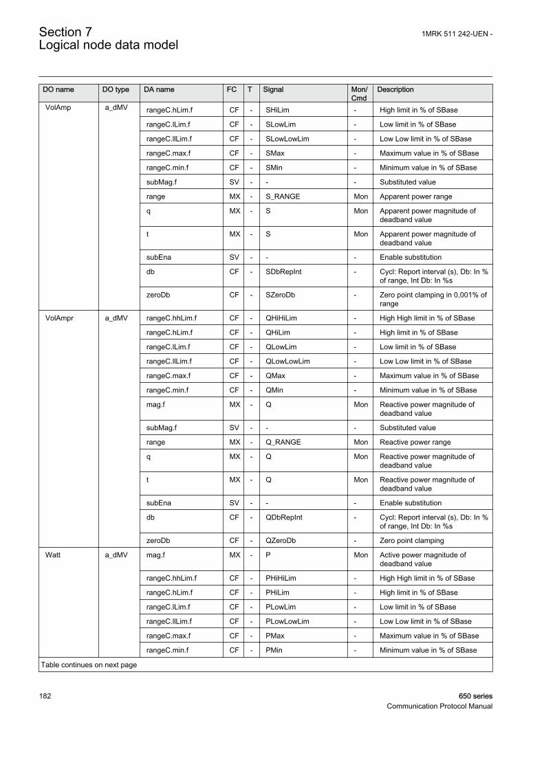
DO name DO type DA name FC T Signal Mon/Cmd
Description
VolAmp a_dMV rangeC.hLim.f CF - SHiLim - High limit in % of SBase
rangeC.lLim.f CF - SLowLim - Low limit in % of SBase
rangeC.llLim.f CF - SLowLowLim - Low Low limit in % of SBase
rangeC.max.f CF - SMax - Maximum value in % of SBase
rangeC.min.f CF - SMin - Minimum value in % of SBase
subMag.f SV - - - Substituted value
range MX - S_RANGE Mon Apparent power range
q MX - S Mon Apparent power magnitude ofdeadband value
t MX - S Mon Apparent power magnitude ofdeadband value
subEna SV - - - Enable substitution
db CF - SDbRepInt - Cycl: Report interval (s), Db: In %of range, Int Db: In %s
zeroDb CF - SZeroDb - Zero point clamping in 0,001% ofrange
VolAmpr a_dMV rangeC.hhLim.f CF - QHiHiLim - High High limit in % of SBase
rangeC.hLim.f CF - QHiLim - High limit in % of SBase
rangeC.lLim.f CF - QLowLim - Low limit in % of SBase
rangeC.llLim.f CF - QLowLowLim - Low Low limit in % of SBase
rangeC.max.f CF - QMax - Maximum value in % of SBase
rangeC.min.f CF - QMin - Minimum value in % of SBase
mag.f MX - Q Mon Reactive power magnitude ofdeadband value
subMag.f SV - - - Substituted value
range MX - Q_RANGE Mon Reactive power range
q MX - Q Mon Reactive power magnitude ofdeadband value
t MX - Q Mon Reactive power magnitude ofdeadband value
subEna SV - - - Enable substitution
db CF - QDbRepInt - Cycl: Report interval (s), Db: In %of range, Int Db: In %s
zeroDb CF - QZeroDb - Zero point clamping
Watt a_dMV mag.f MX - P Mon Active power magnitude ofdeadband value
rangeC.hhLim.f CF - PHiHiLim - High High limit in % of SBase
rangeC.hLim.f CF - PHiLim - High limit in % of SBase
rangeC.lLim.f CF - PLowLim - Low limit in % of SBase
rangeC.llLim.f CF - PLowLowLim - Low Low limit in % of SBase
rangeC.max.f CF - PMax - Maximum value in % of SBase
rangeC.min.f CF - PMin - Minimum value in % of SBase
Table continues on next page
Section 7 1MRK 511 242-UEN -Logical node data model
182 650 seriesCommunication Protocol Manual

DO name DO type DA name FC T Signal Mon/Cmd
Description
Watt a_dMV subMag.f SV - - - Substituted value
range MX - P_RANGE Mon Active power range
q MX - P Mon Active power magnitude ofdeadband value
t MX - P Mon Active power magnitude ofdeadband value
subEna SV - - - Enable substitution
db CF - PDbRepInt - Cycl: Report interval (s), Db: In %of range, Int Db: In %s
zeroDb CF - PZeroDb - Zero point clamping
ALd v1_dSPS stVal ST - ILEAD Mon Current is leading voltage
q ST - ILEAD Mon Current is leading voltage
t ST - ILEAD Mon Current is leading voltage
ALg v1_dSPS stVal ST - ILAG Mon Current is lagging voltage
q ST - ILAG Mon Current is lagging voltage
t ST - ILAG Mon Current is lagging voltage
7.9.3 Measurement MMXU
7.9.3.1 Phase current measurement CMMXU
LN type LN prefix LN class Function block name
CMMXU (revision 1) C MMXU CMMXU
Table 136: CMMXU Logical node data (instance 0)
DO name DO type DA name FC T Signal Mon/Cmd
Description
Mod a_dINC Oper.ctlVal CO - - Cmd Mode parameter for 61850
Oper.origin.orCat CO - - Cmd Mode parameter for 61850
Oper.origin.orIdent CO - - Cmd Mode parameter for 61850
Oper.ctlNum CO - - Cmd Mode parameter for 61850
Oper.T CO - - Cmd Mode parameter for 61850
Oper.Test CO - - Cmd Mode parameter for 61850
Oper.Check CO - - Cmd Mode parameter for 61850
stVal ST - - Mon Mode status parameter for 61850
q ST - - Mon Mode status parameter for 61850
t ST - - Mon Mode status parameter for 61850
Beh a_dINS stVal ST - Beh Mon Behaviour parameter for 61850
q ST - Beh Mon Behaviour parameter for 61850
Table continues on next page
1MRK 511 242-UEN - Section 7Logical node data model
650 series 183Communication Protocol Manual

DO name DO type DA name FC T Signal Mon/Cmd
Description
Beh a_dINS t ST - Beh Mon Behaviour parameter for 61850
A a_dWYE rangeC.hhLim.f CF - ILHiHiLim - High High limit (physical value)
rangeC.hhLim.f CF - ILHiHiLim - High High limit (physical value)
rangeC.hhLim.f CF - ILHiHiLim - High High limit (physical value)
rangeC.hLim.f CF - ILHiLim - High limit (physical value)
rangeC.hLim.f CF - ILHiLim - High limit (physical value)
rangeC.hLim.f CF - ILHiLim - High limit (physical value)
rangeC.lLim.f CF - ILLowLim - Low limit (physical value)
rangeC.lLim.f CF - ILLowLim - Low limit (physical value)
rangeC.lLim.f CF - ILLowLim - Low limit (physical value)
rangeC.llLim.f CF - ILLowLowLim - Low Low limit (physical value)
rangeC.llLim.f CF - ILLowLowLim - Low Low limit (physical value)
rangeC.llLim.f CF - ILLowLowLim - Low Low limit (physical value)
rangeC.min.f CF - ILMin - Minimum value
rangeC.min.f CF - ILMin - Minimum value
rangeC.min.f CF - ILMin - Minimum value
rangeC.max.f CF - ILMax - Maximum value
rangeC.max.f CF - ILMax - Maximum value
rangeC.max.f CF - ILMax - Maximum value
cVal.mag.f MX - IL1 Mon IL1 Amplitude
cVal.mag.f MX - IL2 Mon IL2 Amplitude
cVal.mag.f MX - IL3 Mon IL3 Amplitude
subCVal.mag.f SV - - - Substituted value
subCVal.mag.f SV - - - Substituted value
subCVal.mag.f SV - - - Substituted value
range MX - IL3RANG Mon IL3 Amplitude range
range MX - IL1RANG Mon IL1 Amplitude range
range MX - IL2RANG Mon IL2 Amplitude range
q MX - IL3 Mon IL3 Amplitude
q MX - IL2 Mon IL2 Amplitude
q MX - IL1 Mon IL1 Amplitude
t MX - IL1 Mon IL1 Amplitude
t MX - IL2 Mon IL2 Amplitude
t MX - IL3 Mon IL3 Amplitude
subEna SV - - - Enable substitution
subEna SV - - - Enable substitution
subEna SV - - - Enable substitution
db CF - ILDbRepInt - Cycl: Report interval (s), Db: In %of range, Int Db: In %s
Table continues on next page
Section 7 1MRK 511 242-UEN -Logical node data model
184 650 seriesCommunication Protocol Manual

DO name DO type DA name FC T Signal Mon/Cmd
Description
A a_dWYE db CF - ILDbRepInt - Cycl: Report interval (s), Db: In %of range, Int Db: In %s
db CF - ILDbRepInt - Cycl: Report interval (s), Db: In %of range, Int Db: In %s
zeroDb CF - ILZeroDb - Zero point clamping
zeroDb CF - ILZeroDb - Zero point clamping
zeroDb CF - ILZeroDb - Zero point clamping
7.9.3.2 Phase-phase voltage measurement VMMXU
LN type LN prefix LN class Function block name
VMMXU (revision 1) V MMXU VMMXU
Table 137: VMMXU Logical node data (instance 1)
DO name DO type DA name FC T Signal Mon/Cmd
Description
PPV a_dDEL rangeC.hhLim.f CF - ULHiHiLim - High High limit (physical value)
rangeC.hhLim.f CF - ULHiHiLim - High High limit (physical value)
rangeC.hhLim.f CF - ULHiHiLim - High High limit (physical value)
rangeC.hLim.f CF - ULHiLim - High limit (physical value)
rangeC.hLim.f CF - ULHiLim - High limit (physical value)
rangeC.hLim.f CF - ULHiLim - High limit (physical value)
rangeC.lLim.f CF - ULLowLim - Low limit (physical value)
rangeC.lLim.f CF - ULLowLim - Low limit (physical value)
rangeC.lLim.f CF - ULLowLim - Low limit (physical value)
rangeC.llLim.f CF - ULLowLowLim - Low Low limit (physical value)
rangeC.llLim.f CF - ULLowLowLim - Low Low limit (physical value)
rangeC.llLim.f CF - ULLowLowLim - Low Low limit (physical value)
rangeC.min.f CF - ULMin - Minimum value
rangeC.min.f CF - ULMin - Minimum value
rangeC.min.f CF - ULMin - Minimum value
rangeC.max.f CF - ULMax - Maximum value
rangeC.max.f CF - ULMax - Maximum value
rangeC.max.f CF - ULMax - Maximum value
cVal.mag.f MX - UL12 Mon UL12 Amplitude
cVal.mag.f MX - UL23 Mon UL23 Amplitude
cVal.mag.f MX - UL31 Mon UL31 Amplitude
subCVal.mag.f SV - - - Substituted value
subCVal.mag.f SV - - - Substituted value
Table continues on next page
1MRK 511 242-UEN - Section 7Logical node data model
650 series 185Communication Protocol Manual

DO name DO type DA name FC T Signal Mon/Cmd
Description
PPV a_dDEL subCVal.mag.f SV - - - Substituted value
range MX - UL31RANG Mon UL31Amplitude range
range MX - UL12RANG Mon UL12 Amplitude range
range MX - UL23RANG Mon UL23 Amplitude range
q MX - UL31 Mon UL31 Amplitude
q MX - UL23 Mon UL23 Amplitude
q MX - UL12 Mon UL12 Amplitude
t MX - UL12 Mon UL12 Amplitude
t MX - UL23 Mon UL23 Amplitude
t MX - UL31 Mon UL31 Amplitude
subEna SV - - - Enable substitution
subEna SV - - - Enable substitution
subEna SV - - - Enable substitution
db CF - ULDbRepInt - Cycl: Report interval (s), Db: In %of range, Int Db: In %s
db CF - ULDbRepInt - Cycl: Report interval (s), Db: In %of range, Int Db: In %s
db CF - ULDbRepInt - Cycl: Report interval (s), Db: In %of range, Int Db: In %s
zeroDb CF - ULZeroDb - Zero point clamping
zeroDb CF - ULZeroDb - Zero point clamping
zeroDb CF - ULZeroDb - Zero point clamping
Mod a_dINC Oper.ctlVal CO - - Cmd Mode parameter for 61850
Oper.origin.orCat CO - - Cmd Mode parameter for 61850
Oper.origin.orIdent CO - - Cmd Mode parameter for 61850
Oper.ctlNum CO - - Cmd Mode parameter for 61850
Oper.T CO - - Cmd Mode parameter for 61850
Oper.Test CO - - Cmd Mode parameter for 61850
Oper.Check CO - - Cmd Mode parameter for 61850
stVal ST - - Mon Mode status parameter for 61850
q ST - - Mon Mode status parameter for 61850
t ST - - Mon Mode status parameter for 61850
Beh a_dINS stVal ST - Beh Mon Behaviour parameter for 61850
q ST - Beh Mon Behaviour parameter for 61850
t ST - Beh Mon Behaviour parameter for 61850
7.9.3.3 Phase-neutral voltage measurement VNMMXU
LN type LN prefix LN class Function block name
VNMMXU (revision 1) VN MMXU VNMMXU
Section 7 1MRK 511 242-UEN -Logical node data model
186 650 seriesCommunication Protocol Manual

Table 138: VNMMXU Logical node data (instance 1)
DO name DO type DA name FC T Signal Mon/Cmd
Description
Mod a_dINC Oper.ctlVal CO - - Cmd Mode parameter for 61850
Oper.origin.orCat CO - - Cmd Mode parameter for 61850
Oper.origin.orIdent CO - - Cmd Mode parameter for 61850
Oper.ctlNum CO - - Cmd Mode parameter for 61850
Oper.T CO - - Cmd Mode parameter for 61850
Oper.Test CO - - Cmd Mode parameter for 61850
Oper.Check CO - - Cmd Mode parameter for 61850
stVal ST - - Mon Mode status parameter for 61850
q ST - - Mon Mode status parameter for 61850
t ST - - Mon Mode status parameter for 61850
Beh a_dINS stVal ST - Beh Mon Behaviour parameter for 61850
q ST - Beh Mon Behaviour parameter for 61850
t ST - Beh Mon Behaviour parameter for 61850
PhV a_dWYE cVal.mag.f MX - UL1 Mon UL1 Amplitude, magnitude ofreported value
cVal.mag.f MX - UL2 Mon UL2 Amplitude, magnitude ofreported value
cVal.mag.f MX - UL3 Mon UL3 Amplitude, magnitude ofreported value
subCVal.mag.f SV - - - Substituted value
subCVal.mag.f SV - - - Substituted value
rangeC.hhLim.f CF - UHiHiLim - High High limit (physical value)
rangeC.hhLim.f CF - UHiHiLim - High High limit (physical value)
rangeC.hhLim.f CF - UHiHiLim - High High limit (physical value)
rangeC.hLim.f CF - UHiLim - High limit (physical value)
rangeC.hLim.f CF - UHiLim - High limit (physical value)
rangeC.hLim.f CF - UHiLim - High limit (physical value)
rangeC.lLim.f CF - ULowLim - Low limit (physical value)
rangeC.lLim.f CF - ULowLim - Low limit (physical value)
rangeC.lLim.f CF - ULowLim - Low limit (physical value)
rangeC.llLim.f CF - ULowLowLim - Low Low limit (physical value)
rangeC.llLim.f CF - ULowLowLim - Low Low limit (physical value)
rangeC.llLim.f CF - ULowLowLim - Low Low limit (physical value)
rangeC.min.f CF - UMin - Minimum value
rangeC.min.f CF - UMin - Minimum value
rangeC.min.f CF - UMin - Minimum value
rangeC.max.f CF - UMax - Maximum value
rangeC.max.f CF - UMax - Maximum value
rangeC.max.f CF - UMax - Maximum value
Table continues on next page
1MRK 511 242-UEN - Section 7Logical node data model
650 series 187Communication Protocol Manual

DO name DO type DA name FC T Signal Mon/Cmd
Description
PhV a_dWYE subCVal.mag.f SV - - - Substituted value
range MX - UL3RANG Mon UL3 Amplitude range
range MX - UL1RANG Mon UL1 Amplitude range
range MX - UL2RANG Mon UL2 Amplitude range
q MX - UL3 Mon UL3 Amplitude, magnitude ofreported value
q MX - UL2 Mon UL2 Amplitude, magnitude ofreported value
q MX - UL1 Mon UL1 Amplitude, magnitude ofreported value
t MX - UL1 Mon UL1 Amplitude, magnitude ofreported value
t MX - UL2 Mon UL2 Amplitude, magnitude ofreported value
t MX - UL3 Mon UL3 Amplitude, magnitude ofreported value
subEna SV - - - Enable substitution
subEna SV - - - Enable substitution
subEna SV - - - Enable substitution
db CF - UDbRepInt - Cycl: Report interval (s), Db: In %of range, Int Db: In %s
db CF - UDbRepInt - Cycl: Report interval (s), Db: In %of range, Int Db: In %s
db CF - UDbRepInt - Cycl: Report interval (s), Db: In %of range, Int Db: In %s
zeroDb CF - UZeroDb - Zero point clamping in 0,001% ofrange
zeroDb CF - UZeroDb - Zero point clamping in 0,001% ofrange
zeroDb CF - UZeroDb - Zero point clamping in 0,001% ofrange
7.9.4 Sequence and imbalance MSQI
7.9.4.1 Current sequence component measurement CMSQI
LN type LN prefix LN class Function block name
CMSQI (revision 2) C MSQI CMSQI
Section 7 1MRK 511 242-UEN -Logical node data model
188 650 seriesCommunication Protocol Manual
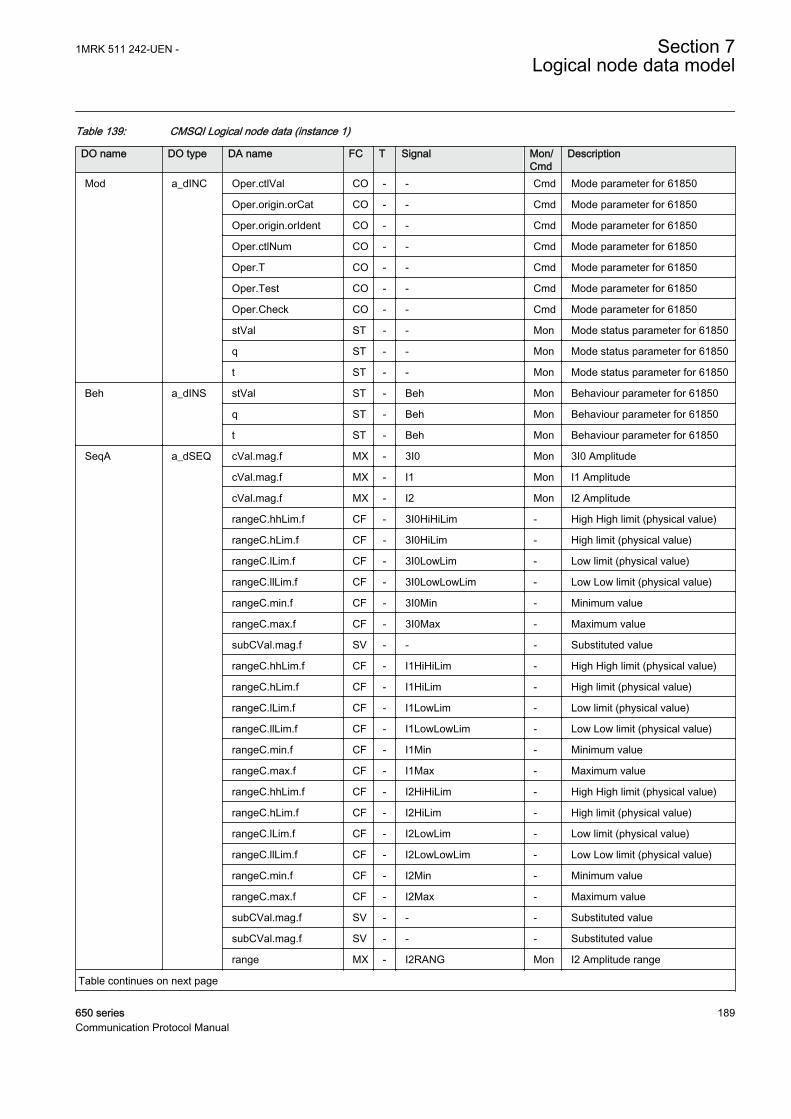
Table 139: CMSQI Logical node data (instance 1)
DO name DO type DA name FC T Signal Mon/Cmd
Description
Mod a_dINC Oper.ctlVal CO - - Cmd Mode parameter for 61850
Oper.origin.orCat CO - - Cmd Mode parameter for 61850
Oper.origin.orIdent CO - - Cmd Mode parameter for 61850
Oper.ctlNum CO - - Cmd Mode parameter for 61850
Oper.T CO - - Cmd Mode parameter for 61850
Oper.Test CO - - Cmd Mode parameter for 61850
Oper.Check CO - - Cmd Mode parameter for 61850
stVal ST - - Mon Mode status parameter for 61850
q ST - - Mon Mode status parameter for 61850
t ST - - Mon Mode status parameter for 61850
Beh a_dINS stVal ST - Beh Mon Behaviour parameter for 61850
q ST - Beh Mon Behaviour parameter for 61850
t ST - Beh Mon Behaviour parameter for 61850
SeqA a_dSEQ cVal.mag.f MX - 3I0 Mon 3I0 Amplitude
cVal.mag.f MX - I1 Mon I1 Amplitude
cVal.mag.f MX - I2 Mon I2 Amplitude
rangeC.hhLim.f CF - 3I0HiHiLim - High High limit (physical value)
rangeC.hLim.f CF - 3I0HiLim - High limit (physical value)
rangeC.lLim.f CF - 3I0LowLim - Low limit (physical value)
rangeC.llLim.f CF - 3I0LowLowLim - Low Low limit (physical value)
rangeC.min.f CF - 3I0Min - Minimum value
rangeC.max.f CF - 3I0Max - Maximum value
subCVal.mag.f SV - - - Substituted value
rangeC.hhLim.f CF - I1HiHiLim - High High limit (physical value)
rangeC.hLim.f CF - I1HiLim - High limit (physical value)
rangeC.lLim.f CF - I1LowLim - Low limit (physical value)
rangeC.llLim.f CF - I1LowLowLim - Low Low limit (physical value)
rangeC.min.f CF - I1Min - Minimum value
rangeC.max.f CF - I1Max - Maximum value
rangeC.hhLim.f CF - I2HiHiLim - High High limit (physical value)
rangeC.hLim.f CF - I2HiLim - High limit (physical value)
rangeC.lLim.f CF - I2LowLim - Low limit (physical value)
rangeC.llLim.f CF - I2LowLowLim - Low Low limit (physical value)
rangeC.min.f CF - I2Min - Minimum value
rangeC.max.f CF - I2Max - Maximum value
subCVal.mag.f SV - - - Substituted value
subCVal.mag.f SV - - - Substituted value
range MX - I2RANG Mon I2 Amplitude range
Table continues on next page
1MRK 511 242-UEN - Section 7Logical node data model
650 series 189Communication Protocol Manual
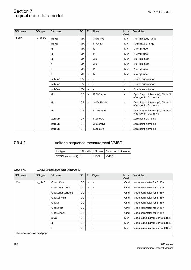
DO name DO type DA name FC T Signal Mon/Cmd
Description
SeqA a_dSEQ range MX - 3I0RANG Mon 3I0 Amplitude range
range MX - I1RANG Mon I1Amplitude range
q MX - I2 Mon I2 Amplitude
q MX - I1 Mon I1 Amplitude
q MX - 3I0 Mon 3I0 Amplitude
t MX - 3I0 Mon 3I0 Amplitude
t MX - I1 Mon I1 Amplitude
t MX - I2 Mon I2 Amplitude
subEna SV - - - Enable substitution
subEna SV - - - Enable substitution
subEna SV - - - Enable substitution
db CF - I2DbRepInt - Cycl: Report interval (s), Db: In %of range, Int Db: In %s
db CF - 3I0DbRepInt - Cycl: Report interval (s), Db: In %of range, Int Db: In %s
db CF - I1DbRepInt - Cycl: Report interval (s), Db: In %of range, Int Db: In %s
zeroDb CF - I1ZeroDb - Zero point clamping
zeroDb CF - 3I0ZeroDb - Zero point clamping
zeroDb CF - I2ZeroDb - Zero point clamping
7.9.4.2 Voltage sequence measurement VMSQI
LN type LN prefix LN class Function block name
VMSQI (revision 2) V MSQI VMSQI
Table 140: VMSQI Logical node data (instance 1)
DO name DO type DA name FC T Signal Mon/Cmd
Description
Mod a_dINC Oper.ctlVal CO - - Cmd Mode parameter for 61850
Oper.origin.orCat CO - - Cmd Mode parameter for 61850
Oper.origin.orIdent CO - - Cmd Mode parameter for 61850
Oper.ctlNum CO - - Cmd Mode parameter for 61850
Oper.T CO - - Cmd Mode parameter for 61850
Oper.Test CO - - Cmd Mode parameter for 61850
Oper.Check CO - - Cmd Mode parameter for 61850
stVal ST - - Mon Mode status parameter for 61850
q ST - - Mon Mode status parameter for 61850
t ST - - Mon Mode status parameter for 61850
Table continues on next page
Section 7 1MRK 511 242-UEN -Logical node data model
190 650 seriesCommunication Protocol Manual

DO name DO type DA name FC T Signal Mon/Cmd
Description
Beh a_dINS stVal ST - Beh Mon Behaviour parameter for 61850
q ST - Beh Mon Behaviour parameter for 61850
t ST - Beh Mon Behaviour parameter for 61850
SeqV a_dSEQ cVal.mag.f MX - 3U0 Mon 3U0 Amplitude
cVal.mag.f MX - U1 Mon U1 Amplitude
cVal.mag.f MX - U2 Mon U2 Amplitude
rangeC.hhLim.f CF - 3U0HiHiLim - High High limit (physical value)
rangeC.hLim.f CF - 3U0HiLim - High limit (physical value)
rangeC.lLim.f CF - 3U0LowLim - Low limit (physical value)
rangeC.llLim.f CF - 3U0LowLowLim - Low Low limit (physical value)
rangeC.min.f CF - 3U0Min - Minimum value
rangeC.max.f CF - 3U0Max - Maximum value
subCVal.mag.f SV - - - Substituted value
rangeC.hhLim.f CF - U1HiHiLim - High High limit (physical value)
rangeC.hLim.f CF - U1HiLim - High limit (physical value)
rangeC.lLim.f CF - U1LowLim - Low limit (physical value)
rangeC.llLim.f CF - U1LowLowLim - Low Low limit (physical value)
rangeC.min.f CF - U1Min - Minimum value
rangeC.max.f CF - U1Max - Maximum value
rangeC.hhLim.f CF - U2HiHiLim - High High limit (physical value)
rangeC.hLim.f CF - U2HiLim - High limit (physical value)
rangeC.lLim.f CF - U2LowLim - Low limit (physical value)
rangeC.llLim.f CF - U2LowLowLim - Low Low limit (physical value)
rangeC.min.f CF - U2Min - Minimum value
rangeC.max.f CF - U2Max - Maximum value
subCVal.mag.f SV - - - Substituted value
subCVal.mag.f SV - - - Substituted value
range MX - U2RANG Mon U2 Amplitude range
range MX - 3U0RANG Mon 3U0 Amplitude range
range MX - U1RANG Mon U1 Amplitude range
q MX - U2 Mon U2 Amplitude
q MX - U1 Mon U1 Amplitude
q MX - 3U0 Mon 3U0 Amplitude
t MX - 3U0 Mon 3U0 Amplitude
t MX - U1 Mon U1 Amplitude
t MX - U2 Mon U2 Amplitude
subEna SV - - - Enable substitution
subEna SV - - - Enable substitution
subEna SV - - - Enable substitution
Table continues on next page
1MRK 511 242-UEN - Section 7Logical node data model
650 series 191Communication Protocol Manual

DO name DO type DA name FC T Signal Mon/Cmd
Description
SeqV a_dSEQ db CF - U2DbRepInt - Cycl: Report interval (s), Db: In %of range, Int Db: In %s
db CF - 3U0DbRepInt - Cycl: Report interval (s), Db: In %of range, Int Db: In %s
db CF - U1DbRepInt - Cycl: Report interval (s), Db: In %of range, Int Db: In %s
zeroDb CF - U1ZeroDb - Zero point clamping
zeroDb CF - 3U0ZeroDb - Zero point clamping
zeroDb CF - U2ZeroDb - Zero point clamping
7.10 Logical nodes for sensors and monitoring
7.10.1 Circuit breaker monitoring SCBR
7.10.1.1 Breaker close/trip circuit monitoring TCSSCBR
LN type LN prefix LN class Function block name
TCSSCBR (revision 0) TCS SCBR TCSSCBR
Table 141: TCSSCBR Logical node data (instance 0)
DO name DO type DA name FC T Signal Mon/Cmd
Description
Mod a_dINC Oper.ctlVal CO - - Cmd Mode parameter for 61850
Oper.origin.orCat CO - - Cmd Mode parameter for 61850
Oper.origin.orIdent CO - - Cmd Mode parameter for 61850
Oper.ctlNum CO - - Cmd Mode parameter for 61850
Oper.T CO - - Cmd Mode parameter for 61850
Oper.Test CO - - Cmd Mode parameter for 61850
Oper.Check CO - - Cmd Mode parameter for 61850
stVal ST - - Mon Mode status parameter for 61850
q ST - - Mon Mode status parameter for 61850
t ST - - Mon Mode status parameter for 61850
Beh a_dINS stVal ST - Beh Mon Behaviour parameter for 61850
q ST - Beh Mon Behaviour parameter for 61850
t ST - Beh Mon Behaviour parameter for 61850
TrCctAlm a_dSPS stVal ST - ALARM Mon Trip circuit fault indication
q ST - ALARM Mon Trip circuit fault indication
t ST - ALARM Mon Trip circuit fault indication
Section 7 1MRK 511 242-UEN -Logical node data model
192 650 seriesCommunication Protocol Manual

7.10.1.2 Circuit breaker condition monitoring SSCBR
LN type LN prefix LN class Function block name
SSCBR (revision 0) S SCBR SSCBR
Table 142: SSCBR Logical node data (instance 0)
DO name DO type DA name FC T Signal Mon/Cmd
Description
Mod a_dINC Oper.ctlVal CO - - Cmd Mode parameter for 61850
Oper.origin.orCat CO - - Cmd Mode parameter for 61850
Oper.origin.orIdent CO - - Cmd Mode parameter for 61850
Oper.ctlNum CO - - Cmd Mode parameter for 61850
Oper.T CO - - Cmd Mode parameter for 61850
Oper.Test CO - - Cmd Mode parameter for 61850
Oper.Check CO - - Cmd Mode parameter for 61850
stVal ST - - Mon Mode status parameter for 61850
q ST - - Mon Mode status parameter for 61850
t ST - - Mon Mode status parameter for 61850
Beh a_dINS stVal ST - Beh Mon Behaviour parameter for 61850
q ST - Beh Mon Behaviour parameter for 61850
t ST - Beh Mon Behaviour parameter for 61850
InaTmdCnt v1_dINS stVal ST - NOOPRDAY Mon The number of days CB has beeninactive
q ST - NOOPRDAY Mon The number of days CB has beeninactive
t ST - NOOPRDAY Mon The number of days CB has beeninactive
RmnLifPhA v1_dINS stVal ST - CBLIFEL1 Mon CB Remaining life phase L1
q ST - CBLIFEL1 Mon CB Remaining life phase L1
t ST - CBLIFEL1 Mon CB Remaining life phase L1
RmnLifPhB v1_dINS stVal ST - CBLIFEL2 Mon CB Remaining life phase L2
q ST - CBLIFEL2 Mon CB Remaining life phase L2
t ST - CBLIFEL2 Mon CB Remaining life phase L2
RmnLifPhC v1_dINS stVal ST - CBLIFEL3 Mon CB Remaining life phase L3
q ST - CBLIFEL3 Mon CB Remaining life phase L3
t ST - CBLIFEL3 Mon CB Remaining life phase L3
RsAccAPwr v1_dSPC Oper.ctlVal CO - - Cmd Command parameter forIEC61850
Oper.origin.orCat CO - - Cmd Command parameter forIEC61850
Oper.origin.orIdent CO - - Cmd Command parameter forIEC61850
Table continues on next page
1MRK 511 242-UEN - Section 7Logical node data model
650 series 193Communication Protocol Manual

DO name DO type DA name FC T Signal Mon/Cmd
Description
RsAccAPwr v1_dSPC Oper.ctlNum CO - - Cmd Command parameter forIEC61850
Oper.T CO - - Cmd Command parameter forIEC61850
Oper.Test CO - - Cmd Command parameter forIEC61850
Oper.Check CO - - Cmd Command parameter forIEC61850
RsCBWear v1_dSPC Oper.ctlVal CO - - Cmd Command parameter forIEC61850
Oper.origin.orCat CO - - Cmd Command parameter forIEC61850
Oper.origin.orIdent CO - - Cmd Command parameter forIEC61850
Oper.ctlNum CO - - Cmd Command parameter forIEC61850
Oper.T CO - - Cmd Command parameter forIEC61850
Oper.Test CO - - Cmd Command parameter forIEC61850
Oper.Check CO - - Cmd Command parameter forIEC61850
RsTrvTm v1_dSPC Oper.ctlVal CO - - Cmd Command parameter forIEC61850
Oper.origin.orCat CO - - Cmd Command parameter forIEC61850
Oper.origin.orIdent CO - - Cmd Command parameter forIEC61850
Oper.ctlNum CO - - Cmd Command parameter forIEC61850
Oper.T CO - - Cmd Command parameter forIEC61850
Oper.Test CO - - Cmd Command parameter forIEC61850
Oper.Check CO - - Cmd Command parameter forIEC61850
RsSprChaTm v1_dSPC Oper.ctlVal CO - - Cmd Command parameter forIEC61850
Oper.origin.orCat CO - - Cmd Command parameter forIEC61850
Oper.origin.orIdent CO - - Cmd Command parameter forIEC61850
Oper.ctlNum CO - - Cmd Command parameter forIEC61850
Oper.T CO - - Cmd Command parameter forIEC61850
Oper.Test CO - - Cmd Command parameter forIEC61850
Table continues on next page
Section 7 1MRK 511 242-UEN -Logical node data model
194 650 seriesCommunication Protocol Manual

DO name DO type DA name FC T Signal Mon/Cmd
Description
RsSprChaTm v1_dSPC Oper.Check CO - - Cmd Command parameter forIEC61850
OpnAlm v1_dSPS stVal ST - TRVTOAL Mon CB open travel time exceeded setvalue
q ST - TRVTOAL Mon CB open travel time exceeded setvalue
t ST - TRVTOAL Mon CB open travel time exceeded setvalue
ClsAlm v1_dSPS stVal ST - TRVTCAL Mon CB close travel time exceededset value
q ST - TRVTCAL Mon CB close travel time exceededset value
t ST - TRVTCAL Mon CB close travel time exceededset value
OpNumAlm v1_dSPS stVal ST - OPRALM Mon Number of CB operationsexceeds alarm limit
q ST - OPRALM Mon Number of CB operationsexceeds alarm limit
t ST - OPRALM Mon Number of CB operationsexceeds alarm limit
OpNumLO v1_dSPS stVal ST - OPRLOALM Mon Number of CB operationsexceeds lockout limit
q ST - OPRLOALM Mon Number of CB operationsexceeds lockout limit
t ST - OPRLOALM Mon Number of CB operationsexceeds lockout limit
APwrAlm v1_dSPS stVal ST - IACCALM Mon Accumulated currents power(Iyt),exceeded alarm limit
q ST - IACCALM Mon Accumulated currents power(Iyt),exceeded alarm limit
t ST - IACCALM Mon Accumulated currents power(Iyt),exceeded alarm limit
APwrLO v1_dSPS stVal ST - IACCLOAL Mon Accumulated currents power(Iyt),exceeded lockout limit
q ST - IACCLOAL Mon Accumulated currents power(Iyt),exceeded lockout limit
t ST - IACCLOAL Mon Accumulated currents power(Iyt),exceeded lockout limit
LonTmAlm v1_dSPS stVal ST - NOOPRALM Mon CB 'not operated for long time'alarm
q ST - NOOPRALM Mon CB 'not operated for long time'alarm
t ST - NOOPRALM Mon CB 'not operated for long time'alarm
SprChaAlm v1_dSPS stVal ST - SPRCHRAL Mon Spring charging time has crossedthe set value
q ST - SPRCHRAL Mon Spring charging time has crossedthe set value
Table continues on next page
1MRK 511 242-UEN - Section 7Logical node data model
650 series 195Communication Protocol Manual

DO name DO type DA name FC T Signal Mon/Cmd
Description
SprChaAlm v1_dSPS t ST - SPRCHRAL Mon Spring charging time has crossedthe set value
PosOpn v1_dSPS stVal ST - CBOPEN Mon CB is in open position
q ST - CBOPEN Mon CB is in open position
t ST - CBOPEN Mon CB is in open position
PosIvd v1_dSPS stVal ST - CBINVPOS Mon CB is in intermediate position
q ST - CBINVPOS Mon CB is in intermediate position
t ST - CBINVPOS Mon CB is in intermediate position
PosCls v1_dSPS stVal ST - CBCLOSED Mon CB is in closed position
q ST - CBCLOSED Mon CB is in closed position
t ST - CBCLOSED Mon CB is in closed position
CBLifAlm v1_dSPS stVal ST - CBLIFEAL Mon Remaining life of CB exceededalarm limit
q ST - CBLIFEAL Mon Remaining life of CB exceededalarm limit
t ST - CBLIFEAL Mon Remaining life of CB exceededalarm limit
PresLO v1_dSPS stVal ST - PRESLO Mon Pressure below lockout level
q ST - PRESLO Mon Pressure below lockout level
t ST - PRESLO Mon Pressure below lockout level
TmmsCls v2_dMV mag.f MX - CBCLTRVT Mon Travel time of the CB duringclosing operation
q MX - CBCLTRVT Mon Travel time of the CB duringclosing operation
t MX - CBCLTRVT Mon Travel time of the CB duringclosing operation
TmmsOpn v2_dMV mag.f MX - CBOTRVT Mon Travel time of the CB duringopening operation
q MX - CBOTRVT Mon Travel time of the CB duringopening operation
t MX - CBOTRVT Mon Travel time of the CB duringopening operation
TmsSprCha v2_dMV mag.f MX - SPRCHRT Mon The charging time of the CB spring
q MX - SPRCHRT Mon The charging time of the CB spring
t MX - SPRCHRT Mon The charging time of the CB spring
AccAPwrPhB v2_dMV mag.f MX - IACCL2 Mon Accumulated currents power (Iyt),phase L2
q MX - IACCL2 Mon Accumulated currents power (Iyt),phase L2
t MX - IACCL2 Mon Accumulated currents power (Iyt),phase L2
AccAPwrPhC v2_dMV mag.f MX - IACCL3 Mon Accumulated currents power (Iyt),phase L3
q MX - IACCL3 Mon Accumulated currents power (Iyt),phase L3
Table continues on next page
Section 7 1MRK 511 242-UEN -Logical node data model
196 650 seriesCommunication Protocol Manual

DO name DO type DA name FC T Signal Mon/Cmd
Description
AccAPwrPhC v2_dMV t MX - IACCL3 Mon Accumulated currents power (Iyt),phase L3
AccAPwrPhA v2_dMV mag.f MX - IACCL1 Mon Accumulated currents power (Iyt),phase L1
q MX - IACCL1 Mon Accumulated currents power (Iyt),phase L1
t MX - IACCL1 Mon Accumulated currents power (Iyt),phase L1
PresAlm v3_dSPS stVal ST - PRESALM Mon Pressure below alarm level
q ST - PRESALM Mon Pressure below alarm level
t ST - PRESALM Mon Pressure below alarm level
OpCnt v5_dINS stVal ST - NO_OPR Mon Number of CB operation cycle
q ST - NO_OPR Mon Number of CB operation cycle
t ST - NO_OPR Mon Number of CB operation cycle
7.10.2 Insulation medium supervision (gas) SIMG
7.10.2.1 Insulation gas monitoring function SSIMG
LN type LN prefix LN class Function block name
SSIMG (revision 0) S SIMG SSIMG
Table 143: SSIMG Logical node data (instance 1)
DO name DO type DA name FC T Signal Mon/Cmd
Description
Mod a_dINC Oper.ctlVal CO - - Cmd Mode parameter for 61850
Oper.origin.orCat CO - - Cmd Mode parameter for 61850
Oper.origin.orIdent CO - - Cmd Mode parameter for 61850
Oper.ctlNum CO - - Cmd Mode parameter for 61850
Oper.T CO - - Cmd Mode parameter for 61850
Oper.Test CO - - Cmd Mode parameter for 61850
Oper.Check CO - - Cmd Mode parameter for 61850
stVal ST - - Mon Mode status parameter for 61850
q ST - - Mon Mode status parameter for 61850
t ST - - Mon Mode status parameter for 61850
Beh a_dINS stVal ST - Beh Mon Behaviour parameter for 61850
q ST - Beh Mon Behaviour parameter for 61850
t ST - Beh Mon Behaviour parameter for 61850
InsAlm a_dSPS stVal ST - PRES_LO Mon Pressure below lockout level
q ST - PRES_LO Mon Pressure below lockout level
Table continues on next page
1MRK 511 242-UEN - Section 7Logical node data model
650 series 197Communication Protocol Manual
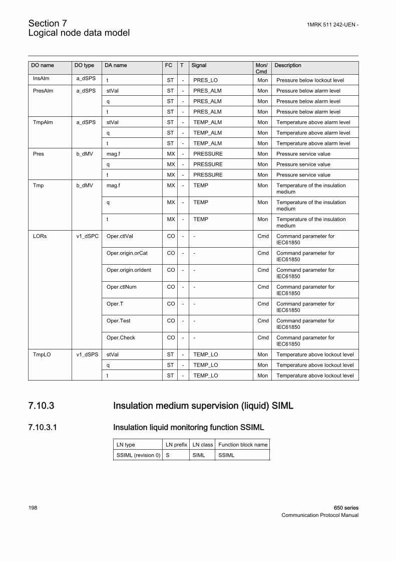
DO name DO type DA name FC T Signal Mon/Cmd
Description
InsAlm a_dSPS t ST - PRES_LO Mon Pressure below lockout level
PresAlm a_dSPS stVal ST - PRES_ALM Mon Pressure below alarm level
q ST - PRES_ALM Mon Pressure below alarm level
t ST - PRES_ALM Mon Pressure below alarm level
TmpAlm a_dSPS stVal ST - TEMP_ALM Mon Temperature above alarm level
q ST - TEMP_ALM Mon Temperature above alarm level
t ST - TEMP_ALM Mon Temperature above alarm level
Pres b_dMV mag.f MX - PRESSURE Mon Pressure service value
q MX - PRESSURE Mon Pressure service value
t MX - PRESSURE Mon Pressure service value
Tmp b_dMV mag.f MX - TEMP Mon Temperature of the insulationmedium
q MX - TEMP Mon Temperature of the insulationmedium
t MX - TEMP Mon Temperature of the insulationmedium
LORs v1_dSPC Oper.ctlVal CO - - Cmd Command parameter forIEC61850
Oper.origin.orCat CO - - Cmd Command parameter forIEC61850
Oper.origin.orIdent CO - - Cmd Command parameter forIEC61850
Oper.ctlNum CO - - Cmd Command parameter forIEC61850
Oper.T CO - - Cmd Command parameter forIEC61850
Oper.Test CO - - Cmd Command parameter forIEC61850
Oper.Check CO - - Cmd Command parameter forIEC61850
TmpLO v1_dSPS stVal ST - TEMP_LO Mon Temperature above lockout level
q ST - TEMP_LO Mon Temperature above lockout level
t ST - TEMP_LO Mon Temperature above lockout level
7.10.3 Insulation medium supervision (liquid) SIML
7.10.3.1 Insulation liquid monitoring function SSIML
LN type LN prefix LN class Function block name
SSIML (revision 0) S SIML SSIML
Section 7 1MRK 511 242-UEN -Logical node data model
198 650 seriesCommunication Protocol Manual

Table 144: SSIML Logical node data (instance 1)
DO name DO type DA name FC T Signal Mon/Cmd
Description
Mod a_dINC Oper.ctlVal CO - - Cmd Mode parameter for 61850
Oper.origin.orCat CO - - Cmd Mode parameter for 61850
Oper.origin.orIdent CO - - Cmd Mode parameter for 61850
Oper.ctlNum CO - - Cmd Mode parameter for 61850
Oper.T CO - - Cmd Mode parameter for 61850
Oper.Test CO - - Cmd Mode parameter for 61850
Oper.Check CO - - Cmd Mode parameter for 61850
stVal ST - - Mon Mode status parameter for 61850
q ST - - Mon Mode status parameter for 61850
t ST - - Mon Mode status parameter for 61850
Beh a_dINS stVal ST - Beh Mon Behaviour parameter for 61850
q ST - Beh Mon Behaviour parameter for 61850
t ST - Beh Mon Behaviour parameter for 61850
InsAlm a_dSPS stVal ST - LVL_LO Mon Level below lockout level
q ST - LVL_LO Mon Level below lockout level
t ST - LVL_LO Mon Level below lockout level
PresAlm a_dSPS stVal ST - LVL_ALM Mon Level below alarm level
q ST - LVL_ALM Mon Level below alarm level
t ST - LVL_ALM Mon Level below alarm level
TmpAlm a_dSPS stVal ST - TEMP_ALM Mon Temperature above alarm level
q ST - TEMP_ALM Mon Temperature above alarm level
t ST - TEMP_ALM Mon Temperature above alarm level
Pres b_dMV mag.f MX - LEVEL Mon Level service value
q MX - LEVEL Mon Level service value
t MX - LEVEL Mon Level service value
Tmp b_dMV mag.f MX - TEMP Mon Temperature of the insulationmedium
q MX - TEMP Mon Temperature of the insulationmedium
t MX - TEMP Mon Temperature of the insulationmedium
LORs v1_dSPC Oper.ctlVal CO - - Cmd Command parameter forIEC61850
Oper.origin.orCat CO - - Cmd Command parameter forIEC61850
Oper.origin.orIdent CO - - Cmd Command parameter forIEC61850
Oper.ctlNum CO - - Cmd Command parameter forIEC61850
Oper.T CO - - Cmd Command parameter forIEC61850
Table continues on next page
1MRK 511 242-UEN - Section 7Logical node data model
650 series 199Communication Protocol Manual

DO name DO type DA name FC T Signal Mon/Cmd
Description
LORs v1_dSPC Oper.Test CO - - Cmd Command parameter forIEC61850
Oper.Check CO - - Cmd Command parameter forIEC61850
TmpLo v1_dSPS stVal ST - TEMP_LO Mon Temperature above lockout level
q ST - TEMP_LO Mon Temperature above lockout level
t ST - TEMP_LO Mon Temperature above lockout level
7.11 Logical nodes for switchgear
7.11.1 Circuit breaker XCBR
7.11.1.1 Apparatus control SXCBR
LN type LN prefix LN class Function block name
SXCBR (revision 1) S XCBR SXCBR
Table 145: SXCBR Logical node data (instance 1)
DO name DO type DA name FC T Signal Mon/Cmd
Description
Mod a_dINC Oper.ctlVal CO - - Cmd Mode parameter for 61850
Oper.origin.orCat CO - - Cmd Mode parameter for 61850
Oper.origin.orIdent CO - - Cmd Mode parameter for 61850
Oper.ctlNum CO - - Cmd Mode parameter for 61850
Oper.T CO - - Cmd Mode parameter for 61850
Oper.Test CO - - Cmd Mode parameter for 61850
Oper.Check CO - - Cmd Mode parameter for 61850
stVal ST - - Mon Mode status value parameter for61850
q ST - - Mon Mode status value parameter for61850
t ST - - Mon Mode status value parameter for61850
Beh a_dINS stVal ST - Beh Mon Behaviour parameter for 61850
q ST - Beh Mon Behaviour parameter for 61850
t ST - Beh Mon Behaviour parameter for 61850
BlkCls a_dSPC Oper.ctlVal CO - - Cmd Special block command value
Oper.origin.orCat CO - - Cmd Special block command value
Oper.origin.orIdent CO - - Cmd Special block command value
Table continues on next page
Section 7 1MRK 511 242-UEN -Logical node data model
200 650 seriesCommunication Protocol Manual

DO name DO type DA name FC T Signal Mon/Cmd
Description
BlkCls a_dSPC Oper.ctlNum CO - - Cmd Special block command value
Oper.T CO - - Cmd Special block command value
Oper.Test CO - - Cmd Special block command value
Oper.Check CO - - Cmd Special block command value
stVal ST - CL_BLKD Mon Indication that the function isblocked for close commands
q ST - CL_BLKD Mon Indication that the function isblocked for close commands
t ST - CL_BLKD Mon Indication that the function isblocked for close commands
BlkOpn a_dSPC Oper.ctlVal CO - - Cmd Special block command value
Oper.origin.orCat CO - - Cmd Special block command value
Oper.origin.orIdent CO - - Cmd Special block command value
Oper.ctlNum CO - - Cmd Special block command value
Oper.T CO - - Cmd Special block command value
Oper.Test CO - - Cmd Special block command value
Oper.Check CO - - Cmd Special block command value
stVal ST - OP_BLKD Mon Indication that the function isblocked for open commands
q ST - OP_BLKD Mon Indication that the function isblocked for open commands
t ST - OP_BLKD Mon Indication that the function isblocked for open commands
Loc a_dSPS stVal ST - - Mon Indication that the function is inlocal mode (process level)
q ST - - Mon Indication that the function is inlocal mode (process level)
t ST - - Mon Indication that the function is inlocal mode (process level)
OpCnt b_dINS stVal ST - CNT_VAL Mon Operation counter value
q ST - CNT_VAL Mon Operation counter value
t ST - CNT_VAL Mon Operation counter value
Pos c_dDPC stVal ST - POSITION Mon Apparatus position indication
q ST - POSITION Mon Apparatus position indication
t ST - POSITION Mon Apparatus position indication
subEna SV - - - Substitute enable
subVal SV - - - Substituted double position value
CBOpCap h_dINS stVal ST - - Mon Breaker operating capability 1 =None, 2 = O, 3 = CO, 4 = OCO, 5= COCO, 6+ = More
q ST - - Mon Breaker operating capability 1 =None, 2 = O, 3 = CO, 4 = OCO, 5= COCO, 6+ = More
Table continues on next page
1MRK 511 242-UEN - Section 7Logical node data model
650 series 201Communication Protocol Manual
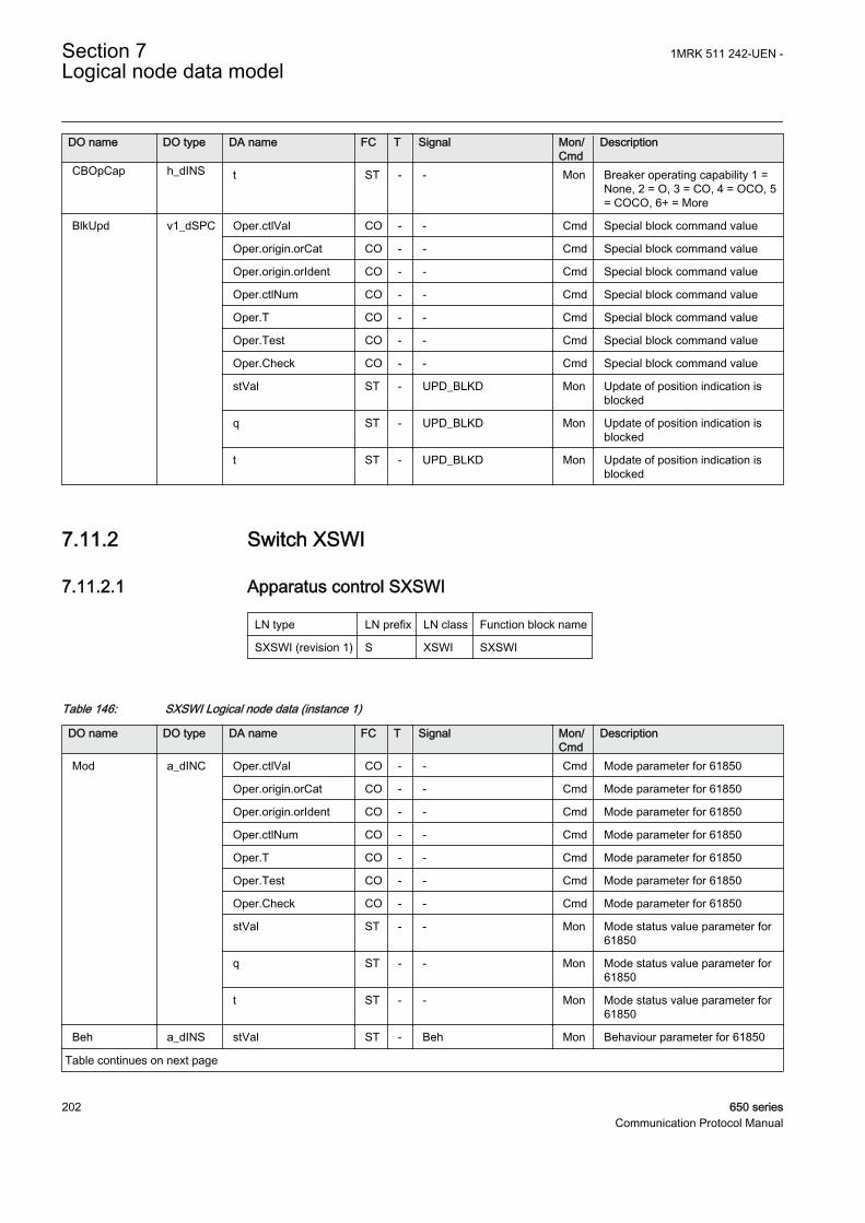
DO name DO type DA name FC T Signal Mon/Cmd
Description
CBOpCap h_dINS t ST - - Mon Breaker operating capability 1 =None, 2 = O, 3 = CO, 4 = OCO, 5= COCO, 6+ = More
BlkUpd v1_dSPC Oper.ctlVal CO - - Cmd Special block command value
Oper.origin.orCat CO - - Cmd Special block command value
Oper.origin.orIdent CO - - Cmd Special block command value
Oper.ctlNum CO - - Cmd Special block command value
Oper.T CO - - Cmd Special block command value
Oper.Test CO - - Cmd Special block command value
Oper.Check CO - - Cmd Special block command value
stVal ST - UPD_BLKD Mon Update of position indication isblocked
q ST - UPD_BLKD Mon Update of position indication isblocked
t ST - UPD_BLKD Mon Update of position indication isblocked
7.11.2 Switch XSWI
7.11.2.1 Apparatus control SXSWI
LN type LN prefix LN class Function block name
SXSWI (revision 1) S XSWI SXSWI
Table 146: SXSWI Logical node data (instance 1)
DO name DO type DA name FC T Signal Mon/Cmd
Description
Mod a_dINC Oper.ctlVal CO - - Cmd Mode parameter for 61850
Oper.origin.orCat CO - - Cmd Mode parameter for 61850
Oper.origin.orIdent CO - - Cmd Mode parameter for 61850
Oper.ctlNum CO - - Cmd Mode parameter for 61850
Oper.T CO - - Cmd Mode parameter for 61850
Oper.Test CO - - Cmd Mode parameter for 61850
Oper.Check CO - - Cmd Mode parameter for 61850
stVal ST - - Mon Mode status value parameter for61850
q ST - - Mon Mode status value parameter for61850
t ST - - Mon Mode status value parameter for61850
Beh a_dINS stVal ST - Beh Mon Behaviour parameter for 61850
Table continues on next page
Section 7 1MRK 511 242-UEN -Logical node data model
202 650 seriesCommunication Protocol Manual

DO name DO type DA name FC T Signal Mon/Cmd
Description
Beh a_dINS q ST - Beh Mon Behaviour parameter for 61850
t ST - Beh Mon Behaviour parameter for 61850
BlkCls a_dSPC Oper.ctlVal CO - - Cmd Special block command value
Oper.origin.orCat CO - - Cmd Special block command value
Oper.origin.orIdent CO - - Cmd Special block command value
Oper.ctlNum CO - - Cmd Special block command value
Oper.T CO - - Cmd Special block command value
Oper.Test CO - - Cmd Special block command value
Oper.Check CO - - Cmd Special block command value
stVal ST - CL_BLKD Mon Indication that the function isblocked for close commands
q ST - CL_BLKD Mon Indication that the function isblocked for close commands
t ST - CL_BLKD Mon Indication that the function isblocked for close commands
BlkOpn a_dSPC Oper.ctlVal CO - - Cmd Special block command value
Oper.origin.orCat CO - - Cmd Special block command value
Oper.origin.orIdent CO - - Cmd Special block command value
Oper.ctlNum CO - - Cmd Special block command value
Oper.T CO - - Cmd Special block command value
Oper.Test CO - - Cmd Special block command value
Oper.Check CO - - Cmd Special block command value
stVal ST - OP_BLKD Mon Indication that the function isblocked for open commands
q ST - OP_BLKD Mon Indication that the function isblocked for open commands
t ST - OP_BLKD Mon Indication that the function isblocked for open commands
Loc a_dSPS stVal ST - - Mon Indication that the function is inlocal mode (process level)
q ST - - Mon Indication that the function is inlocal mode (process level)
t ST - - Mon Indication that the function is inlocal mode (process level)
OpCnt b_dINS stVal ST - CNT_VAL Mon Operation counter value
q ST - CNT_VAL Mon Operation counter value
t ST - CNT_VAL Mon Operation counter value
Pos c_dDPC stVal ST - POSITION Mon Apparatus position indication
q ST - POSITION Mon Apparatus position indication
t ST - POSITION Mon Apparatus position indication
subEna SV - - - Substitute enable
subVal SV - - - Substituted double position value
Table continues on next page
1MRK 511 242-UEN - Section 7Logical node data model
650 series 203Communication Protocol Manual

DO name DO type DA name FC T Signal Mon/Cmd
Description
SwOpCap f_dINS stVal ST - - Mon Switch operating capability 1 =None, 2 = O, 3 = C, 4 = O & C
q ST - - Mon Switch operating capability 1 =None, 2 = O, 3 = C, 4 = O & C
t ST - - Mon Switch operating capability 1 =None, 2 = O, 3 = C, 4 = O & C
SwTyp g_dINS stVal ST - - Mon 1=LoadBreak,2=Disconnector,3=EarthSw,4=HighSpeedEarthSw
q ST - - Mon 1=LoadBreak,2=Disconnector,3=EarthSw,4=HighSpeedEarthSw
t ST - - Mon 1=LoadBreak,2=Disconnector,3=EarthSw,4=HighSpeedEarthSw
BlkUpd v1_dSPC Oper.ctlVal CO - - Cmd Special block command value
Oper.origin.orCat CO - - Cmd Special block command value
Oper.origin.orIdent CO - - Cmd Special block command value
Oper.ctlNum CO - - Cmd Special block command value
Oper.T CO - - Cmd Special block command value
Oper.Test CO - - Cmd Special block command value
Oper.Check CO - - Cmd Special block command value
stVal ST - UPD_BLKD Mon Update of position indication isblocked
q ST - UPD_BLKD Mon Update of position indication isblocked
t ST - UPD_BLKD Mon Update of position indication isblocked
7.12 Logical nodes for power transformers
7.12.1 Tap changer YLTC
7.12.1.1 Tap changer control and supervision, 6 binary inputs TCMYLTC
LN type LN prefix LN class Function block name
TCMYLTC (revision 1) TCM YLTC TCMYLTC
Section 7 1MRK 511 242-UEN -Logical node data model
204 650 seriesCommunication Protocol Manual

Table 147: TCMYLTC Logical node data (instance 1)
DO name DO type DA name FC T Signal Mon/Cmd
Description
Mod a_dINC Oper.ctlVal CO - - Cmd Mode parameter for 61850
Oper.origin.orCat CO - - Cmd Mode parameter for 61850
Oper.origin.orIdent CO - - Cmd Mode parameter for 61850
Oper.ctlNum CO - - Cmd Mode parameter for 61850
Oper.T CO - - Cmd Mode parameter for 61850
Oper.Test CO - - Cmd Mode parameter for 61850
Oper.Check CO - - Cmd Mode parameter for 61850
stVal ST - - Mon Mode status value parameter for61850
q ST - - Mon Mode status value parameter for61850
t ST - - Mon Mode status value parameter for61850
Beh a_dINS stVal ST - Beh Mon Behaviour parameter for 61850
q ST - Beh Mon Behaviour parameter for 61850
t ST - Beh Mon Behaviour parameter for 61850
EndPosR a_dSPS stVal ST - HIPOSAL Mon Alarm for tap in the highest voltposition
q ST - HIPOSAL Mon Alarm for tap in the highest voltposition
t ST - HIPOSAL Mon Alarm for tap in the highest voltposition
EndPosL a_dSPS stVal ST - LOPOSAL Mon Alarm for tap in the lowest voltposition
q ST - LOPOSAL Mon Alarm for tap in the lowest voltposition
t ST - LOPOSAL Mon Alarm for tap in the lowest voltposition
TapChg b_dBSC valWTr.posVal ST - TCPOS Mon Integer value corresponding toactual tap position
valWTr.transInd ST - - Mon Tap position change in progress
q ST - TCPOS Mon Integer value corresponding toactual tap position
t ST - TCPOS Mon Integer value corresponding toactual tap position
OpCnt b_dINS stVal ST - CNT_VAL Mon Number of operations on tapchanger
q ST - CNT_VAL Mon Number of operations on tapchanger
t ST - CNT_VAL Mon Number of operations on tapchanger
HiTapPos v1_dINS stVal ST - - Mon Tap position for the highestvoltage
Table continues on next page
1MRK 511 242-UEN - Section 7Logical node data model
650 series 205Communication Protocol Manual

DO name DO type DA name FC T Signal Mon/Cmd
Description
HiTapPos v1_dINS q ST - - Mon Tap position for the highestvoltage
t ST - - Mon Tap position for the highestvoltage
LoTapPos v1_dINS stVal ST - - Mon Tap position for the lowest voltage
q ST - - Mon Tap position for the lowest voltage
t ST - - Mon Tap position for the lowest voltage
OpRs v1_dSPC Oper.ctlVal CO - - Cmd Command parameter forIEC61850
Oper.origin.orCat CO - - Cmd Command parameter forIEC61850
Oper.origin.orIdent CO - - Cmd Command parameter forIEC61850
Oper.ctlNum CO - - Cmd Command parameter forIEC61850
Oper.T CO - - Cmd Command parameter forIEC61850
Oper.Test CO - - Cmd Command parameter forIEC61850
Oper.Check CO - - Cmd Command parameter forIEC61850
CLRs v1_dSPC Oper.ctlVal CO - - Cmd Command parameter forIEC61850
Oper.origin.orCat CO - - Cmd Command parameter forIEC61850
Oper.origin.orIdent CO - - Cmd Command parameter forIEC61850
Oper.ctlNum CO - - Cmd Command parameter forIEC61850
Oper.T CO - - Cmd Command parameter forIEC61850
Oper.Test CO - - Cmd Command parameter forIEC61850
Oper.Check CO - - Cmd Command parameter forIEC61850
CmdFlt v1_dSPS stVal ST - CMDERRAL Mon Alarm for a command without anexpected position change
q ST - CMDERRAL Mon Alarm for a command without anexpected position change
t ST - CMDERRAL Mon Alarm for a command without anexpected position change
ConvFlt v1_dSPS stVal ST - CONVERR Mon General tap position conversionerror
q ST - CONVERR Mon General tap position conversionerror
t ST - CONVERR Mon General tap position conversionerror
Table continues on next page
Section 7 1MRK 511 242-UEN -Logical node data model
206 650 seriesCommunication Protocol Manual

DO name DO type DA name FC T Signal Mon/Cmd
Description
InvPosChg v1_dSPS stVal ST - INVALPOS Mon Last position change was aninvalid change
q ST - INVALPOS Mon Last position change was aninvalid change
t ST - INVALPOS Mon Last position change was aninvalid change
TapChgFlt v1_dSPS stVal ST - TCERRAL Mon Alarm for none or illegal tapposition change
q ST - TCERRAL Mon Alarm for none or illegal tapposition change
t ST - TCERRAL Mon Alarm for none or illegal tapposition change
TapPosFlt v1_dSPS stVal ST - POSERRAL Mon Alarm that indicates a problemwith the position indication
q ST - POSERRAL Mon Alarm that indicates a problemwith the position indication
t ST - POSERRAL Mon Alarm that indicates a problemwith the position indication
CLCnt v2_dMV mag.f MX - CLCNT_VAL Mon Remaining number of operationsat rated load
q MX - CLCNT_VAL Mon Remaining number of operationsat rated load
t MX - CLCNT_VAL Mon Remaining number of operationsat rated load
7.13 Logical nodes for further power system equipment
7.13.1 Battery ZBAT
7.13.1.1 Station battery supervision SPVNZBAT
LN type LN prefix LN class Function block name
SPVNZBAT (revision 0) SPVN ZBAT SPVNZBAT
Table 148: SPVNZBAT Logical node data (instance 0)
DO name DO type DA name FC T Signal Mon/Cmd
Description
Mod a_dINC Oper.ctlVal CO - - Cmd Mode parameter for 61850
Oper.origin.orCat CO - - Cmd Mode parameter for 61850
Oper.origin.orIdent CO - - Cmd Mode parameter for 61850
Oper.ctlNum CO - - Cmd Mode parameter for 61850
Oper.T CO - - Cmd Mode parameter for 61850
Table continues on next page
1MRK 511 242-UEN - Section 7Logical node data model
650 series 207Communication Protocol Manual

DO name DO type DA name FC T Signal Mon/Cmd
Description
Mod a_dINC Oper.Test CO - - Cmd Mode parameter for 61850
Oper.Check CO - - Cmd Mode parameter for 61850
stVal ST - - Mon Mode status parameter for 61850
q ST - - Mon Mode status parameter for 61850
t ST - - Mon Mode status parameter for 61850
Beh a_dINS stVal ST - Beh Mon Behaviour parameter for 61850
q ST - Beh Mon Behaviour parameter for 61850
t ST - Beh Mon Behaviour parameter for 61850
BatHi a_dSPS stVal ST - ST_UHI Mon Start signal when battery voltageexceeds upper limit
q ST - ST_UHI Mon Start signal when battery voltageexceeds upper limit
t ST - ST_UHI Mon Start signal when battery voltageexceeds upper limit
BatLo a_dSPS stVal ST - ST_ULOW Mon Start signal when battery voltagedrops below lower limit
q ST - ST_ULOW Mon Start signal when battery voltagedrops below lower limit
t ST - ST_ULOW Mon Start signal when battery voltagedrops below lower limit
Vol b_dMV mag.f MX - BATTVOLT Mon Service value of the batteryterminal voltage
q MX - BATTVOLT Mon Service value of the batteryterminal voltage
t MX - BATTVOLT Mon Service value of the batteryterminal voltage
OpBatLo v1_dSPS stVal ST - AL_ULOW Mon Alarm when voltage has beenbelow low limit for a set time
q ST - AL_ULOW Mon Alarm when voltage has beenbelow low limit for a set time
t ST - AL_ULOW Mon Alarm when voltage has beenbelow low limit for a set time
OpBatHi v1_dSPS stVal ST - AL_UHI Mon Alarm when voltage hasexceeded high limit for a set time
q ST - AL_UHI Mon Alarm when voltage hasexceeded high limit for a set time
t ST - AL_UHI Mon Alarm when voltage hasexceeded high limit for a set time
Section 7 1MRK 511 242-UEN -Logical node data model
208 650 seriesCommunication Protocol Manual

7.14 Logical nodes for station communication
7.14.1 Interlock receive - INTLKRCV
7.14.1.1 Horizontal communication via GOOSE for interlockingGOOSEINTLKRCV
LN type LN prefix LN class Function block name
INTGREC instance 1 (revision 0) INT GREC GOOSEINTLKRCV
Table 149: INTGREC Logical node data (instance 1)
DO name DO type DA name FC T Signal Mon/Cmd
Description
TagApp1 a_dDPS stVal ST - - Mon Internal parameter tag to handle61850 mapping
q ST - - Mon Internal parameter tag to handle61850 mapping
TagApp2 a_dDPS stVal ST - - Mon Internal parameter tag to handle61850 mapping
TagApp3 a_dDPS stVal ST - - Mon Internal parameter tag to handle61850 mapping
TagApp4 a_dDPS stVal ST - - Mon Internal parameter tag to handle61850 mapping
TagApp5 a_dDPS stVal ST - - Mon Internal parameter tag to handle61850 mapping
TagApp6 a_dDPS stVal ST - - Mon Internal parameter tag to handle61850 mapping
TagApp7 a_dDPS stVal ST - - Mon Internal parameter tag to handle61850 mapping
TagApp8 a_dDPS stVal ST - - Mon Internal parameter tag to handle61850 mapping
TagApp9 a_dDPS stVal ST - - Mon Internal parameter tag to handle61850 mapping
TagApp10 a_dDPS stVal ST - - Mon Internal parameter tag to handle61850 mapping
TagApp11 a_dDPS stVal ST - - Mon Internal parameter tag to handle61850 mapping
TagApp12 a_dDPS stVal ST - - Mon Internal parameter tag to handle61850 mapping
TagApp13 a_dDPS stVal ST - - Mon Internal parameter tag to handle61850 mapping
TagApp14 a_dDPS stVal ST - - Mon Internal parameter tag to handle61850 mapping
Table continues on next page
1MRK 511 242-UEN - Section 7Logical node data model
650 series 209Communication Protocol Manual

DO name DO type DA name FC T Signal Mon/Cmd
Description
TagApp15 a_dDPS stVal ST - - Mon Internal parameter tag to handle61850 mapping
TagReservR a_dSPS stVal ST - - Mon Internal parameter tag to handle61850 mapping
TagReservG a_dSPS stVal ST - - Mon Internal parameter tag to handle61850 mapping
7.14.2 Binary Receive - BINRCV
7.14.2.1 Goose binary receive GOOSEBINRCV
LN type LN prefix LN class Function block name
BINGREC instance 1 (revision 0) BIN GREC GOOSEBINRCV
Table 150: BINGREC Logical node data (instance 1)
DO name DO type DA name FC T Signal Mon/Cmd
Description
TagBinOut1 a_dSPS stVal ST - - Mon Internal parameter tag to handle61850 mapping
q ST - - Mon Internal parameter tag to handle61850 mapping
TagBinOut2 a_dSPS stVal ST - - Mon Internal parameter tag to handle61850 mapping
q ST - - Mon Internal parameter tag to handle61850 mapping
TagBinOut3 a_dSPS stVal ST - - Mon Internal parameter tag to handle61850 mapping
TagBinOut4 a_dSPS stVal ST - - Mon Internal parameter tag to handle61850 mapping
TagBinOut5 a_dSPS stVal ST - - Mon Internal parameter tag to handle61850 mapping
TagBinOut6 a_dSPS stVal ST - - Mon Internal parameter tag to handle61850 mapping
TagBinOut7 a_dSPS stVal ST - - Mon Internal parameter tag to handle61850 mapping
TagBinOut8 a_dSPS stVal ST - - Mon Internal parameter tag to handle61850 mapping
TagBinOut9 a_dSPS stVal ST - - Mon Internal parameter tag to handle61850 mapping
TagBinOu10 a_dSPS stVal ST - - Mon Internal parameter tag to handle61850 mapping
TagBinOu11 a_dSPS stVal ST - - Mon Internal parameter tag to handle61850 mapping
TagBinOu12 a_dSPS stVal ST - - Mon Internal parameter tag to handle61850 mapping
Table continues on next page
Section 7 1MRK 511 242-UEN -Logical node data model
210 650 seriesCommunication Protocol Manual

DO name DO type DA name FC T Signal Mon/Cmd
Description
TagBinOu13 a_dSPS stVal ST - - Mon Internal parameter tag to handle61850 mapping
TagBinOu14 a_dSPS stVal ST - - Mon Internal parameter tag to handle61850 mapping
TagBinOu15 a_dSPS stVal ST - - Mon Internal parameter tag to handle61850 mapping
TagBinOu16 a_dSPS stVal ST - - Mon Internal parameter tag to handle61850 mapping
7.14.3 VCTR Receive - VCTRRCV
7.14.3.1 Voltage control receiving block for GOOSE GOOSEVCTRRCV
LN type LN prefix LN class Function block name
VCTRGREC instance 1 (revision 0) VCTR GREC GOOSEVCTRRCV
Table 151: VCTRGREC Logical node data (instance 1)
DO name DO type DA name FC T Signal Mon/Cmd
Description
In_LodAIm V10_dMV mag.f MX - - Mon Imaginary part of load current(horizontal communication)
q MX - - Mon Imaginary part of load current(horizontal communication)
t MX - - Mon Imaginary part of load current(horizontal communication)
In_LodARe V11_dMV mag.f MX - - Mon Real part of load current(horizontal communication)
q MX - - Mon Real part of load current(horizontal communication)
t MX - - Mon Real part of load current(horizontal communication)
In_BusV V12_dMV mag.f MX - - Mon Busbar voltage (horizontalcommunication)
q MX - - Mon Busbar voltage (horizontalcommunication)
t MX - - Mon Busbar voltage (horizontalcommunication)
In_SetV V13_dMV mag.f MX - - Mon Voltage setpoint (horizontalcommunication)
q MX - - Mon Voltage setpoint (horizontalcommunication)
t MX - - Mon Voltage setpoint (horizontalcommunication)
In_PosRel V14_dMV mag.f MX - - Mon Relative tap position (horizontalcommunication)
Table continues on next page
1MRK 511 242-UEN - Section 7Logical node data model
650 series 211Communication Protocol Manual

DO name DO type DA name FC T Signal Mon/Cmd
Description
In_PosRel V14_dMV q MX - - Mon Relative tap position (horizontalcommunication)
t MX - - Mon Relative tap position (horizontalcommunication)
In_X2 V15_dMV mag.f MX - - Mon Transformer reactance secondaryside (horizontal communication)
q MX - - Mon Transformer reactance secondaryside (horizontal communication)
t MX - - Mon Transformer reactance secondaryside (horizontal communication)
In_status V6_dINS stVal ST - - Mon VCTR Control word (horizontalcommunication)
q ST - - Mon VCTR Control word (horizontalcommunication)
t ST - - Mon VCTR Control word (horizontalcommunication)
7.14.4 Double point Receive (DP) - DPRCV
7.14.4.1 GOOSE function block to receive a double point value GOOSEDPRCV
LN type LN prefix LN class Function block name
DPGREC instance 1 (revision 0) DP GREC GOOSEDPRCV
Table 152: DPGREC Logical node data (instance 1)
DO name DO type DA name FC T Signal Mon/Cmd
Description
TagDPOut a_dDPS stVal ST - - Mon Internal parameter tag to handle61850 mapping
q ST - - Mon Internal parameter tag to handle61850 mapping
7.14.5 Integer Receive - INTRCV
7.14.5.1 GOOSE function block to receive an integer value GOOSEINTRCV
LN type LN prefix LN class Function block name
INTSGREC instance 1 (revision 0) INTS GREC GOOSEINTRCV
Section 7 1MRK 511 242-UEN -Logical node data model
212 650 seriesCommunication Protocol Manual
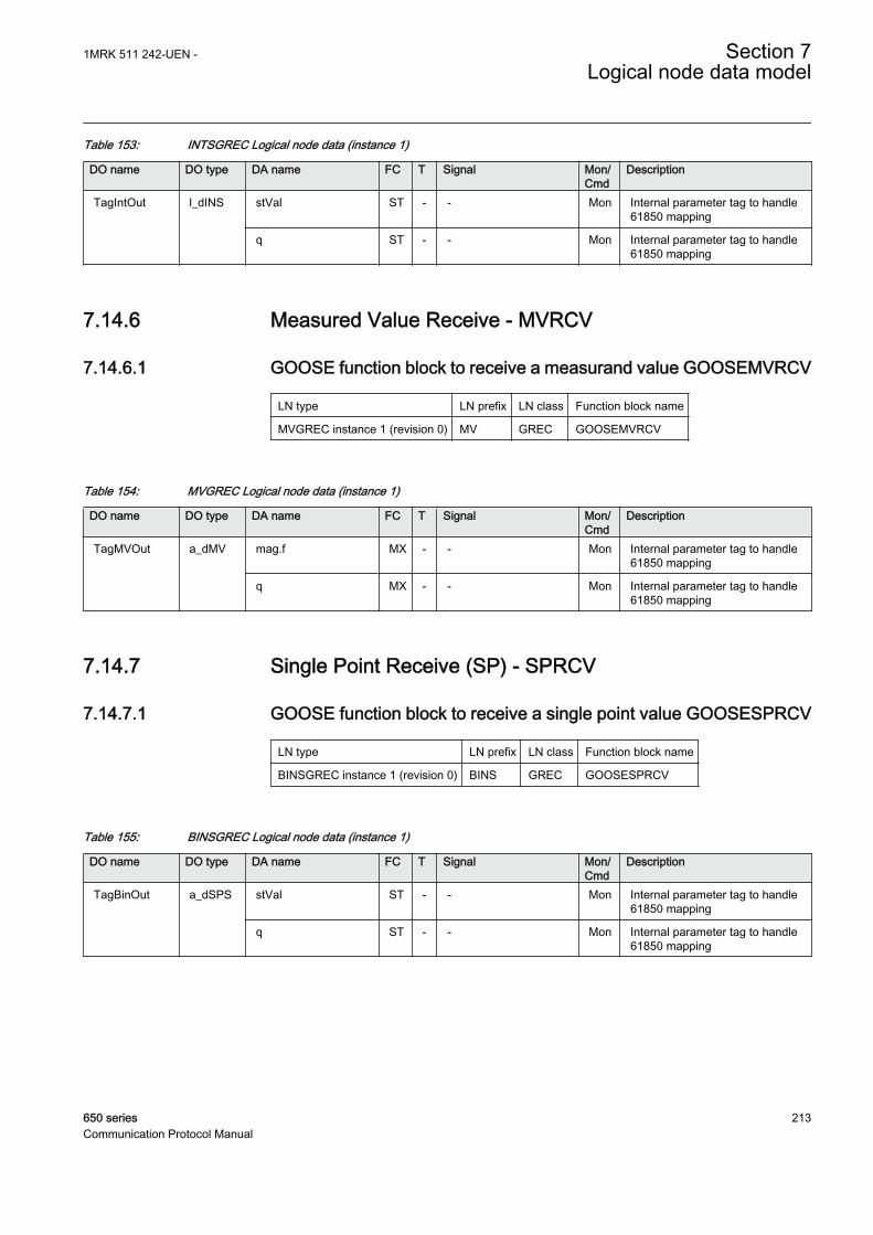
Table 153: INTSGREC Logical node data (instance 1)
DO name DO type DA name FC T Signal Mon/Cmd
Description
TagIntOut l_dINS stVal ST - - Mon Internal parameter tag to handle61850 mapping
q ST - - Mon Internal parameter tag to handle61850 mapping
7.14.6 Measured Value Receive - MVRCV
7.14.6.1 GOOSE function block to receive a measurand value GOOSEMVRCV
LN type LN prefix LN class Function block name
MVGREC instance 1 (revision 0) MV GREC GOOSEMVRCV
Table 154: MVGREC Logical node data (instance 1)
DO name DO type DA name FC T Signal Mon/Cmd
Description
TagMVOut a_dMV mag.f MX - - Mon Internal parameter tag to handle61850 mapping
q MX - - Mon Internal parameter tag to handle61850 mapping
7.14.7 Single Point Receive (SP) - SPRCV
7.14.7.1 GOOSE function block to receive a single point value GOOSESPRCV
LN type LN prefix LN class Function block name
BINSGREC instance 1 (revision 0) BINS GREC GOOSESPRCV
Table 155: BINSGREC Logical node data (instance 1)
DO name DO type DA name FC T Signal Mon/Cmd
Description
TagBinOut a_dSPS stVal ST - - Mon Internal parameter tag to handle61850 mapping
q ST - - Mon Internal parameter tag to handle61850 mapping
1MRK 511 242-UEN - Section 7Logical node data model
650 series 213Communication Protocol Manual

214

Section 8 Glossary
AC Alternating current
ACT Application configuration tool within PCM600
A/D converter Analog-to-digital converter
ADBS Amplitude deadband supervision
AI Analog input
ANSI American National Standards Institute
AR Autoreclosing
ASCT Auxiliary summation current transformer
ASD Adaptive signal detection
AWG American Wire Gauge standard
BI Binary input
BOS Binary outputs status
BR External bistable relay
BS British Standards
CAN Controller Area Network. ISO standard (ISO 11898) forserial communication
CB Circuit breaker
CCITT Consultative Committee for International Telegraph andTelephony. A United Nations-sponsored standards bodywithin the International Telecommunications Union.
CCVT Capacitive Coupled Voltage Transformer
Class C Protection Current Transformer class as per IEEE/ ANSI
CMPPS Combined megapulses per second
CMT Communication Management tool in PCM600
CO cycle Close-open cycle
Codirectional Way of transmitting G.703 over a balanced line. Involvestwo twisted pairs making it possible to transmit informationin both directions
COMTRADE Standard format according to IEC 60255-24
Contra-directional Way of transmitting G.703 over a balanced line. Involvesfour twisted pairs, two of which are used for transmittingdata in both directions and two for transmitting clock signals
1MRK 511 242-UEN - Section 8Glossary
650 series 215Communication Protocol Manual

CPU Central processor unit
CR Carrier receive
CRC Cyclic redundancy check
CROB Control relay output block
CS Carrier send
CT Current transformer
CVT Capacitive voltage transformer
DAR Delayed autoreclosing
DARPA Defense Advanced Research Projects Agency (The USdeveloper of the TCP/IP protocol etc.)
DBDL Dead bus dead line
DBLL Dead bus live line
DC Direct current
DFC Data flow control
DFT Discrete Fourier transform
DHCP Dynamic Host Configuration Protocol
DIP-switch Small switch mounted on a printed circuit board
DI Digital input
DLLB Dead line live bus
DNP Distributed Network Protocol as per IEEE/ANSI Std.1379-2000
DR Disturbance recorder
DRAM Dynamic random access memory
DRH Disturbance report handler
DSP Digital signal processor
DTT Direct transfer trip scheme
EHV network Extra high voltage network
EIA Electronic Industries Association
EMC Electromagnetic compatibility
EMF (Electric Motive Force)
EMI Electromagnetic interference
EnFP End fault protection
EPA Enhanced performance architecture
ESD Electrostatic discharge
FCB Flow control bit; Frame count bit
Section 8 1MRK 511 242-UEN -Glossary
216 650 seriesCommunication Protocol Manual
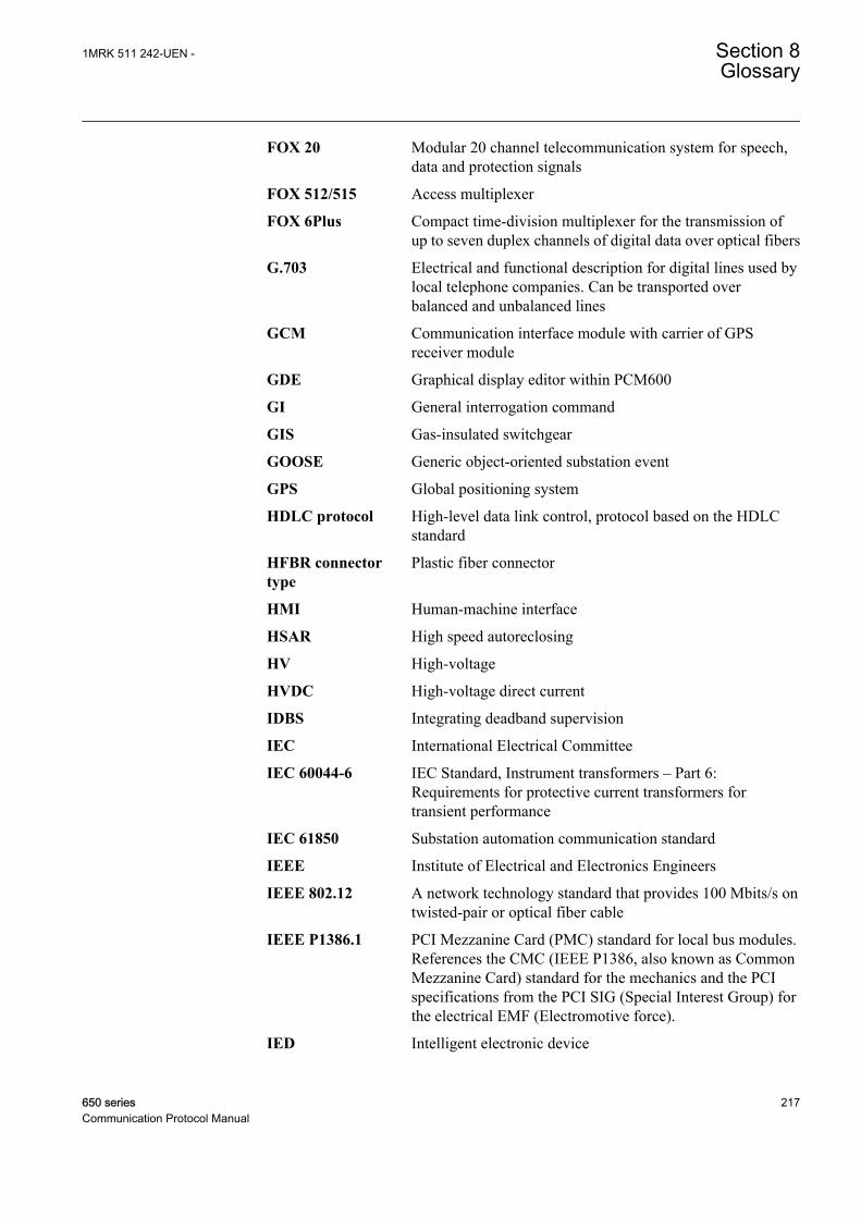
FOX 20 Modular 20 channel telecommunication system for speech,data and protection signals
FOX 512/515 Access multiplexer
FOX 6Plus Compact time-division multiplexer for the transmission ofup to seven duplex channels of digital data over optical fibers
G.703 Electrical and functional description for digital lines used bylocal telephone companies. Can be transported overbalanced and unbalanced lines
GCM Communication interface module with carrier of GPSreceiver module
GDE Graphical display editor within PCM600
GI General interrogation command
GIS Gas-insulated switchgear
GOOSE Generic object-oriented substation event
GPS Global positioning system
HDLC protocol High-level data link control, protocol based on the HDLCstandard
HFBR connectortype
Plastic fiber connector
HMI Human-machine interface
HSAR High speed autoreclosing
HV High-voltage
HVDC High-voltage direct current
IDBS Integrating deadband supervision
IEC International Electrical Committee
IEC 60044-6 IEC Standard, Instrument transformers – Part 6:Requirements for protective current transformers fortransient performance
IEC 61850 Substation automation communication standard
IEEE Institute of Electrical and Electronics Engineers
IEEE 802.12 A network technology standard that provides 100 Mbits/s ontwisted-pair or optical fiber cable
IEEE P1386.1 PCI Mezzanine Card (PMC) standard for local bus modules.References the CMC (IEEE P1386, also known as CommonMezzanine Card) standard for the mechanics and the PCIspecifications from the PCI SIG (Special Interest Group) forthe electrical EMF (Electromotive force).
IED Intelligent electronic device
1MRK 511 242-UEN - Section 8Glossary
650 series 217Communication Protocol Manual

I-GIS Intelligent gas-insulated switchgear
Instance When several occurrences of the same function are availablein the IED, they are referred to as instances of that function.One instance of a function is identical to another of the samekind but has a different number in the IED user interfaces.The word "instance" is sometimes defined as an item ofinformation that is representative of a type. In the same wayan instance of a function in the IED is representative of atype of function.
IP 1. Internet protocol. The network layer for the TCP/IPprotocol suite widely used on Ethernet networks. IP is aconnectionless, best-effort packet-switching protocol. Itprovides packet routing, fragmentation and reassemblythrough the data link layer.2. Ingression protection, according to IEC standard
IP 20 Ingression protection, according to IEC standard, level 20
IP 40 Ingression protection, according to IEC standard, level 40
IP 54 Ingression protection, according to IEC standard, level 54
IRF Internal failure signal
IRIG-B: InterRange Instrumentation Group Time code format B,standard 200
ITU International Telecommunications Union
LAN Local area network
LIB 520 High-voltage software module
LCD Liquid crystal display
LDD Local detection device
LED Light-emitting diode
MCB Miniature circuit breaker
MCM Mezzanine carrier module
MVB Multifunction vehicle bus. Standardized serial bus originallydeveloped for use in trains.
NCC National Control Centre
OCO cycle Open-close-open cycle
OCP Overcurrent protection
OLTC On-load tap changer
OV Over-voltage
Overreach A term used to describe how the relay behaves during a faultcondition. For example, a distance relay is overreachingwhen the impedance presented to it is smaller than the
Section 8 1MRK 511 242-UEN -Glossary
218 650 seriesCommunication Protocol Manual

apparent impedance to the fault applied to the balance point,that is, the set reach. The relay “sees” the fault but perhaps itshould not have seen it.
PCI Peripheral component interconnect, a local data bus
PCM Pulse code modulation
PCM600 Protection and control IED manager
PC-MIP Mezzanine card standard
PISA Process interface for sensors & actuators
PMC PCI Mezzanine card
POR Permissive overreach
POTT Permissive overreach transfer trip
Process bus Bus or LAN used at the process level, that is, in nearproximity to the measured and/or controlled components
PSM Power supply module
PST Parameter setting tool within PCM600
PT ratio Potential transformer or voltage transformer ratio
PUTT Permissive underreach transfer trip
RASC Synchrocheck relay, COMBIFLEX
RCA Relay characteristic angle
RFPP Resistance for phase-to-phase faults
RFPE Resistance for phase-to-earth faults
RISC Reduced instruction set computer
RMS value Root mean square value
RS422 A balanced serial interface for the transmission of digitaldata in point-to-point connections
RS485 Serial link according to EIA standard RS485
RTC Real-time clock
RTU Remote terminal unit
SA Substation Automation
SBO Select-before-operate
SC Switch or push button to close
SCS Station control system
SCADA Supervision, control and data acquisition
SCT System configuration tool according to standard IEC 61850
SDU Service data unit
1MRK 511 242-UEN - Section 8Glossary
650 series 219Communication Protocol Manual

SMA connector Subminiature version A, A threaded connector with constantimpedance.
SMT Signal matrix tool within PCM600
SMS Station monitoring system
SNTP Simple network time protocol – is used to synchronizecomputer clocks on local area networks. This reduces therequirement to have accurate hardware clocks in everyembedded system in a network. Each embedded node caninstead synchronize with a remote clock, providing therequired accuracy.
SRY Switch for CB ready condition
ST Switch or push button to trip
Starpoint Neutral point of transformer or generator
SVC Static VAr compensation
TC Trip coil
TCS Trip circuit supervision
TCP Transmission control protocol. The most common transportlayer protocol used on Ethernet and the Internet.
TCP/IP Transmission control protocol over Internet Protocol. The defacto standard Ethernet protocols incorporated into 4.2BSDUnix. TCP/IP was developed by DARPA for Internetworking and encompasses both network layer and transportlayer protocols. While TCP and IP specify two protocols atspecific protocol layers, TCP/IP is often used to refer to theentire US Department of Defense protocol suite based uponthese, including Telnet, FTP, UDP and RDP.
TNC connector Threaded Neill-Concelman, a threaded constant impedanceversion of a BNC connector
TPZ, TPY, TPX,TPS
Current transformer class according to IEC
UMT User management tool
Underreach A term used to describe how the relay behaves during a faultcondition. For example, a distance relay is underreachingwhen the impedance presented to it is greater than theapparent impedance to the fault applied to the balance point,that is, the set reach. The relay does not “see” the fault butperhaps it should have seen it. See also Overreach.
U/I-PISA Process interface components that deliver measured voltageand current values
UTC Coordinated Universal Time. A coordinated time scale,maintained by the Bureau International des Poids et Mesures(BIPM), which forms the basis of a coordinated
Section 8 1MRK 511 242-UEN -Glossary
220 650 seriesCommunication Protocol Manual

dissemination of standard frequencies and time signals. UTCis derived from International Atomic Time (TAI) by theaddition of a whole number of "leap seconds" to synchronizeit with Universal Time 1 (UT1), thus allowing for theeccentricity of the Earth's orbit, the rotational axis tilt (23.5degrees), but still showing the Earth's irregular rotation, onwhich UT1 is based. The Coordinated Universal Time isexpressed using a 24-hour clock, and uses the Gregoriancalendar. It is used for aeroplane and ship navigation, whereit is also sometimes known by the military name, "Zulutime." "Zulu" in the phonetic alphabet stands for "Z", whichstands for longitude zero.
UV Undervoltage
WEI Weak end infeed logic
VT Voltage transformer
X.21 A digital signalling interface primarily used for telecomequipment
3IO Three times zero-sequence current. Often referred to as theresidual or the earth-fault current
3UO Three times the zero sequence voltage. Often referred to asthe residual voltage or the neutral point voltage
1MRK 511 242-UEN - Section 8Glossary
650 series 221Communication Protocol Manual

222

223

Contact us
ABB ABSubstation Automation ProductsSE-721 59 Västerås, SwedenPhone +46 (0) 21 32 50 00Fax +46 (0) 21 14 69 18
www.abb.com/substationautomation
1MR
K 5
11 2
42-U
EN
-©
Cop
yrig
ht 2
011
AB
B. A
ll rig
hts
rese
rved
.
Recommended