AUTODESK LABS
ICOPY ADD-IN FOR INVENTOR TUTORIAL
iCopy for Inventor® Tutorial
Introduction
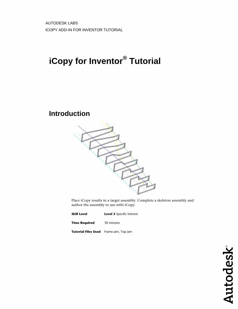
Place iCopy results in a target assembly. Complete a skeleton assembly andauthor the assembly to use with iCopy.
Skill Level Level 3 Specific Interest
Time Required 30 minutes
Tutorial Files Used Frame.iam, Top.iam
ICOPY ADD-IN FOR INVENTOR TUTORIAL
Learn how to
Place iCopy results■
Complete a skeleton assembly■
Prepare an assembly for the iCopy Author■
Author an iCopy template■
Prerequisites
Know how to navigate the model space with the various view tools, and ■perform common modeling functions, such as sketching and selectinggeometry.
Have a basic understanding of adaptivity and how it affects parts and■assemblies.
Understand the basics of skeleton modeling.■
The iCopy command automates the process of copying and positioning similarcomponents in the main assembly. iCopy combines skeletal modeling and adaptivity to allow the subassembly to change shape to fit its position in the model. The iCopy Author command creates an iCopy template from an adaptive skeleton assembly. The iCopy command creates one or multiple copies of the iCopy template and adds each copy to the target assembly. Each assembly (iCopy result) can vary slightly from other iCopy results in thepattern depending on the adaptivity that was used in the iCopy template.
Navigation Tips
Use the Show button in the upper-left corner to display the table of■contents for this tutorial with navigation links to each page.
Use the Forward button in the upper-right corner to advance to the next ■page.
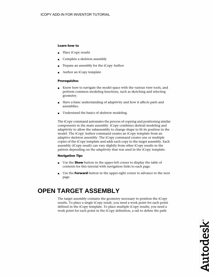
OPEN TARGET ASSEMBLYThe target assembly contains the geometry necessary to position the iCopy results. To place a single iCopy result, you need a work point for each point defined in the iCopy template. To place multiple iCopy results, you need a work point for each point in the iCopy definition, a rail to define the path
ICOPY ADD-IN FOR INVENTOR TUTORIAL
for each work point, a work plane to define the position of the iCopy results,and a path for the pattern.
1 Open Target.iam.
2 The assembly contains a single part. The part contains sketch geometryand work points. You use the work points to position iCopy results.
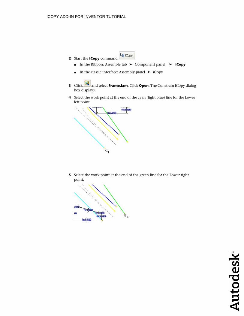
ICOPYUse the iCopy command to position iCopy results. First, select the iCopy template to use. Then select geometry to position, size and pattern the iCopyresults, and control the copy or reuse of components.
1 Start the iCopy command.
In the Ribbon: Assemble tab ➤ Component panel ➤ iCopy■
In the classic interface: Assembly panel ➤ iCopy■
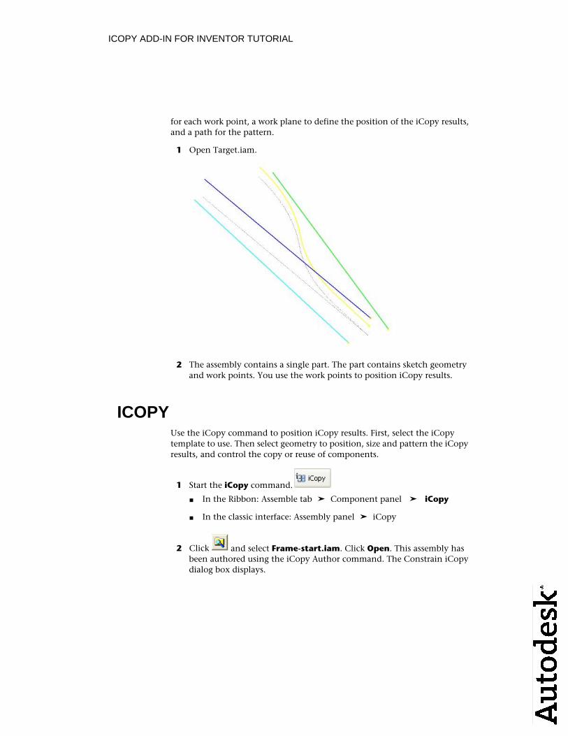
2 Click and select Frame-start.iam. Click Open. This assembly hasbeen authored using the iCopy Author command. The Constrain iCopydialog box displays.
ICOPY ADD-IN FOR INVENTOR TUTORIAL
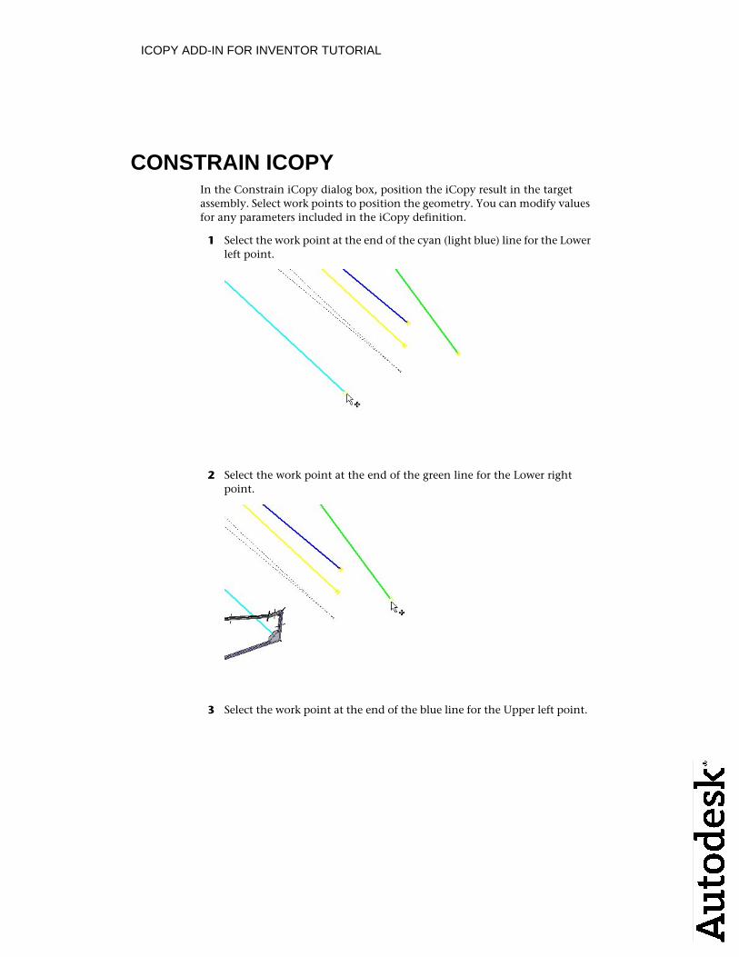
CONSTRAIN ICOPYIn the Constrain iCopy dialog box, position the iCopy result in the targetassembly. Select work points to position the geometry. You can modify values for any parameters included in the iCopy definition.
1 Select the work point at the end of the cyan (light blue) line for the Lower left point.
2 Select the work point at the end of the green line for the Lower right point.
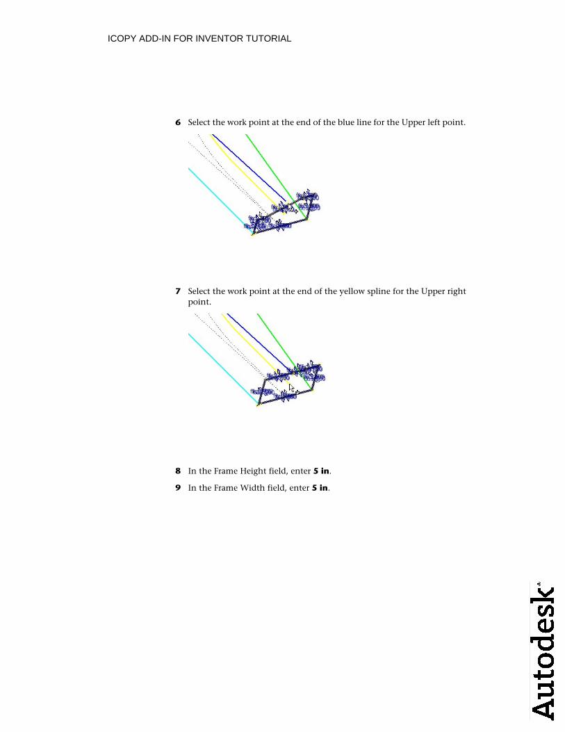
3 Select the work point at the end of the blue line for the Upper left point.
ICOPY ADD-IN FOR INVENTOR TUTORIAL
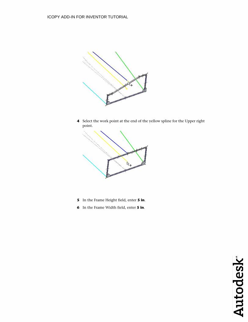
4 Select the work point at the end of the yellow spline for the Upper rightpoint.
5 In the Frame Height field, enter 5 in.
6 In the Frame Width field, enter 5 in.

ICOPY ADD-IN FOR INVENTOR TUTORIAL
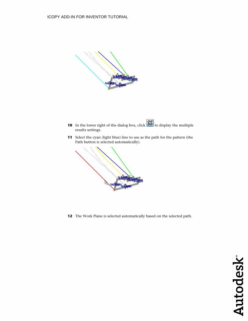
7 In the lower right of the dialog box, click in the lower right of thedialog box to display the multiple results settings.
CONSTRAIN ICOPY - PATTERNIn the Constrain iCopy dialog box, in the multiple mode, pattern the iCopyresults in the target assembly. Rails are automatically selected based on thework points used to position the iCopy. The rails control the positioning of work points for additional iCopy results. You select a path to determine the direction of the iCopy results pattern. A work plane is used to determine the position of the iCopy results. This work plane is selected automatically.
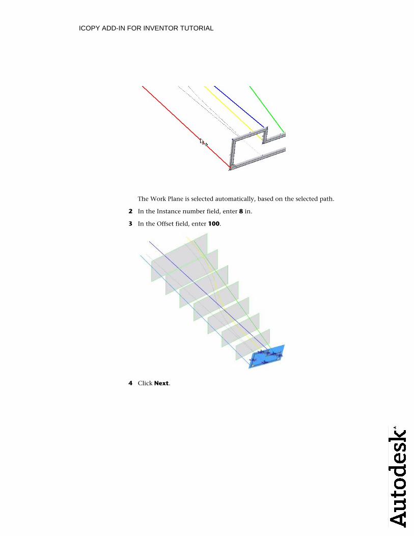
1 Select the cyan (light blue) line to use as the path for the pattern (the Path button is selected automatically).
ICOPY ADD-IN FOR INVENTOR TUTORIAL
The Work Plane is selected automatically, based on the selected path.
2 In the Instance number field, enter 8 in.
3 In the Offset field, enter 100.
4 Click Next.
ICOPY ADD-IN FOR INVENTOR TUTORIAL
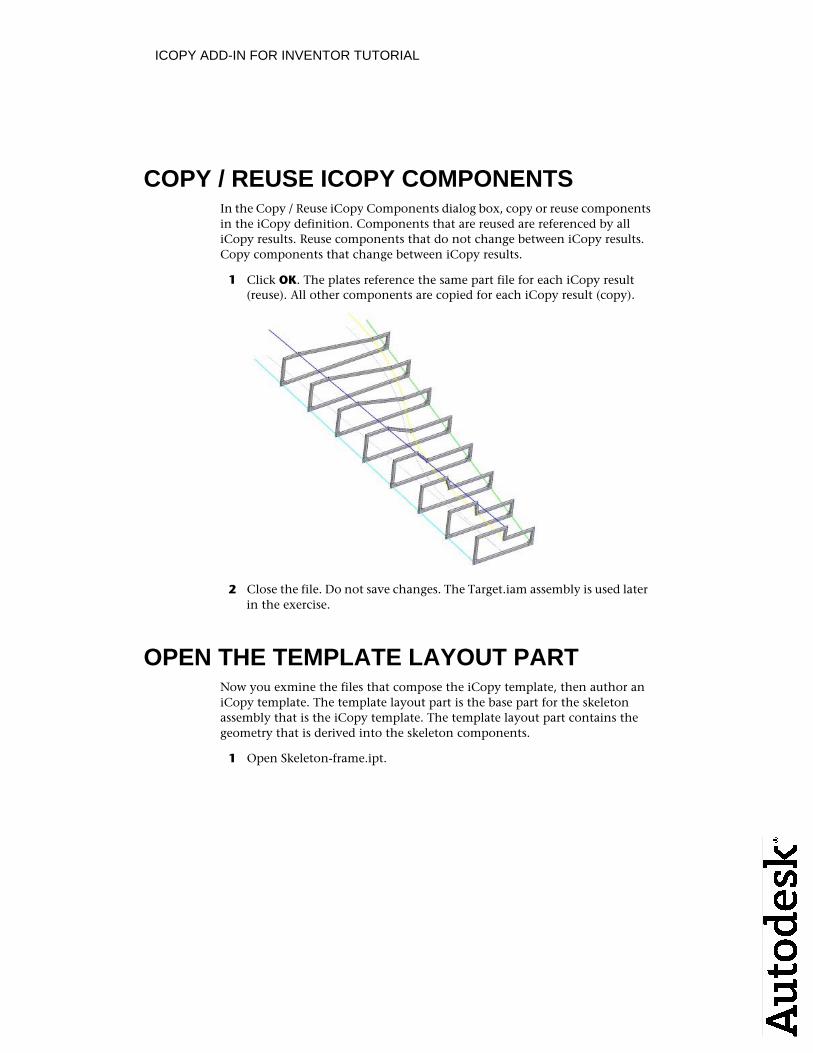
COPY / REUSE ICOPY COMPONENTS In the Copy / Reuse iCopy Components dialog box, copy or reuse componentsin the iCopy definition. Components that are reused are referenced by all iCopy results. Reuse components that do not change between iCopy results.Copy components that change between iCopy results.
1 Click OK. The plates reference the same part file for each iCopy result (reuse). All other components are copied for each iCopy result (copy).
2 Close the file. Do not save changes. The Target.iam assembly is used later in the exercise.
OPEN THE TEMPLATE LAYOUT PARTNow you exmine the files that compose the iCopy template, then author aniCopy template. The template layout part is the base part for the skeleton assembly that is the iCopy template. The template layout part contains thegeometry that is derived into the skeleton components.
1 Open Skeleton-frame.ipt.
ICOPY ADD-IN FOR INVENTOR TUTORIAL
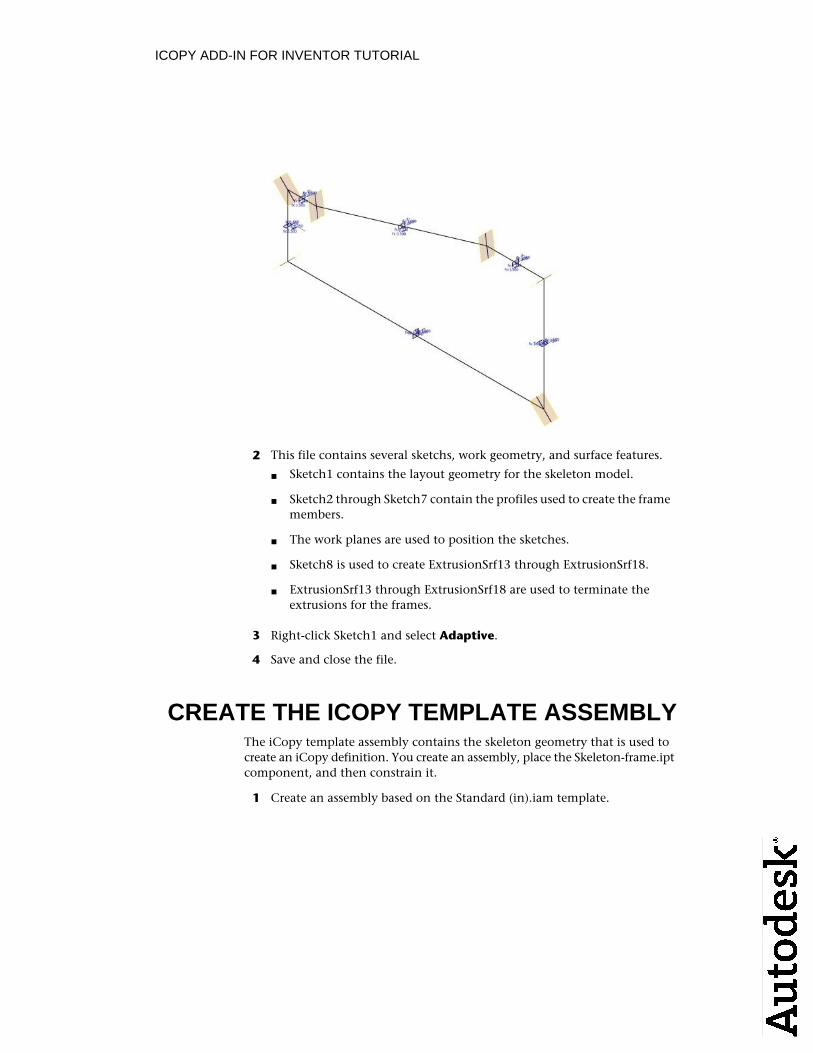
2 This file contains several sketchs, work geometry, and surface features.
Sketch1 contains the layout geometry for the skeleton model.■
Sketch2 through Sketch7 contain the profiles used to create the frame■members.
The work planes are used to position the sketches.■
Sketch8 is used to create ExtrusionSrf13 through ExtrusionSrf18.■
ExtrusionSrf13 through ExtrusionSrf18 are used to terminate the■extrusions for the frames.
3 Right-click Sketch1 and select Adaptive.
4 Save and close the file.
CREATE THE ICOPY TEMPLATE ASSEMBLYThe iCopy template assembly contains the skeleton geometry that is used tocreate an iCopy definition. You create an assembly, place the Skeleton-frame.iptcomponent, and then constrain it.
1 Create an assembly based on the Standard (in).iam template.
ICOPY ADD-IN FOR INVENTOR TUTORIAL
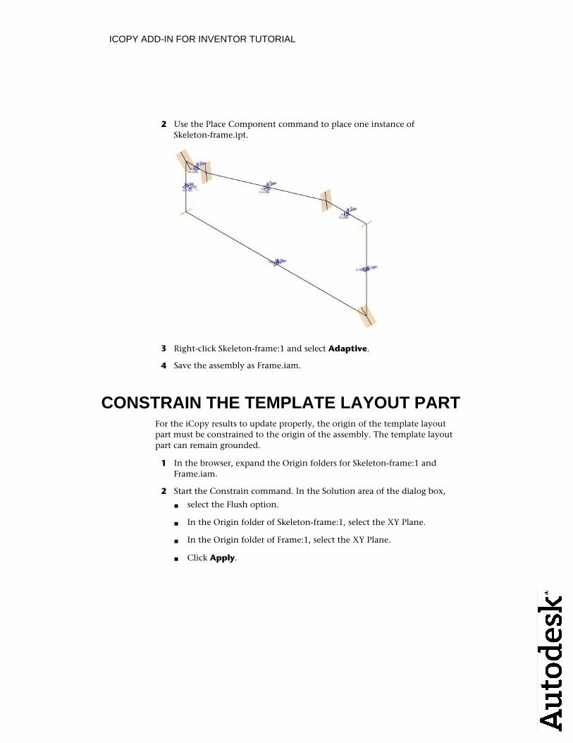
2 Use the Place Component command to place one instance ofSkeleton-frame.ipt.
3 Right-click Skeleton-frame:1 and select Adaptive.
4 Save the assembly as Frame.iam.
CONSTRAIN THE TEMPLATE LAYOUT PART For the iCopy results to update properly, the origin of the template layout part must be constrained to the origin of the assembly. The template layoutpart can remain grounded.
1 In the browser, expand the Origin folders for Skeleton-frame:1 and Frame.iam.
2 Start the Constrain command. In the Solution area of the dialog box,
select the Flush option.■
In the Origin folder of Skeleton-frame:1, select the XY Plane. ■
In the Origin folder of Frame:1, select the XY Plane.■
Click Apply.■
ICOPY ADD-IN FOR INVENTOR TUTORIAL
3 Repeat to create flush constraints between XZ/XZ planes and YZ/YZ planes.
ICOPY AUTHOR - LAYOUT TABThe iCopy Author prepares an assembly for the iCopy command. To use anassembly as an iCopy template, the assembly must contain a skeleton partthat drives the other parts in the assembly. The skeleton part must containan adaptive sketch. You select points in the sketch to use as the control pointsfor placing the iCopy. The parameters in the skeleton part can be added tothe iCopy template. These parameters give greater control over the size andshape of the assembly and its components.
1 Start the iCopy Author command.
In the Ribbon: Manage tab ➤ Author panel ➤ iCopy Author ■
In the classic interface: Assembly panel ➤ iCopy Author ■
2 In the browser, select Skeleton-frame:1. After the layout part is selected,the Geometry and Parameter tabs become available.
ICOPY AUTHOR - GEOMETRY TABOn the Geometry tab, select and name the control points in the layout part.The control points are used to position the iCopy result when it is placed inan assembly. These points must be geometry points (end points of lines, centerpoints of circles, but not sketch points).
1 Select the Geometry tab.
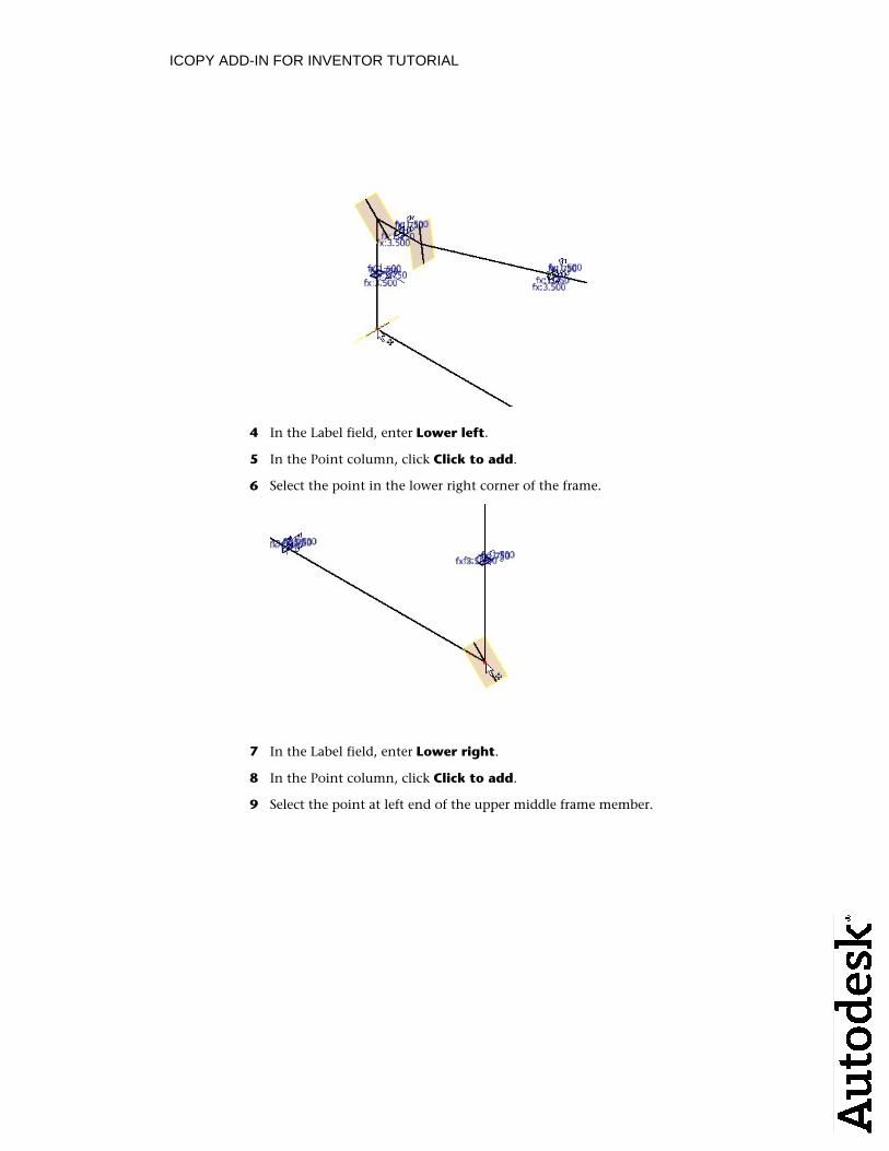
2 In the Point column, click Click to add.
3 Select the point in the lower left corner of the frame.
ICOPY ADD-IN FOR INVENTOR TUTORIAL
4 In the Label field, enter Lower left.
5 In the Point column, click Click to add.
6 Select the point in the lower right corner of the frame.
7 In the Label field, enter Lower right.
8 In the Point column, click Click to add.
9 Select the point at left end of the upper middle frame member.
ICOPY ADD-IN FOR INVENTOR TUTORIAL
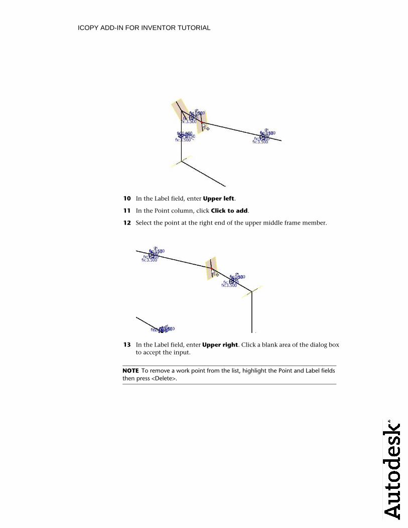
10 In the Label field, enter Upper left.
11 In the Point column, click Click to add.
12 Select the point at the right end of the upper middle frame member.
13 In the Label field, enter Upper right. Click a blank area of the dialog boxto accept the input.
NOTE To remove a work point from the list, highlight the Point and Label fieldsthen press <Delete>.
ICOPY ADD-IN FOR INVENTOR TUTORIAL
ICOPY AUTHOR - PARAMETER TABOn the Parameter tab, include parameters from the layout part in the iCopy template. You can modify the parameter values when placing the iCopy inthe target assembly.
1 Select the Parameter tab. There are two parameters in the list on the right.These parameters are user parameters defined in Skeleton-frame.
2 Select the Label field for FrameH and enter Frame Height.
3 Select the Label field for FrameW and enter Frame Width. Click a blank area of the dialog box to accept the value.
4 Click OK.
5 Save the file. Click Yes to all if prompted.
6 Close Frame.iam.
TEST THE ICOPY DEFINITIONWhen creating an iCopy definition, test the iCopy with just the skeleton. Test again after you create all the derived parts. Then finally test after placing anyother components. You test the iCopy definition by using it with the iCopy command to verify it updates as expected.
1 Open Target.iam.
ICOPY ADD-IN FOR INVENTOR TUTORIAL
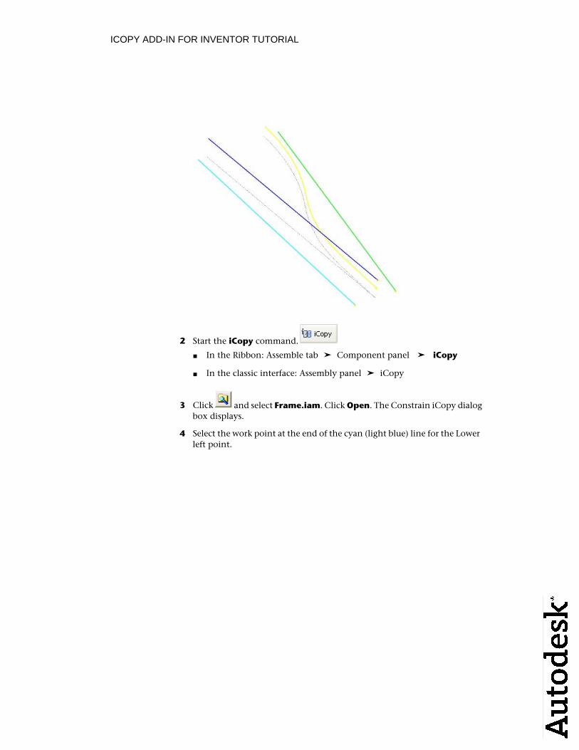
2 Start the iCopy command.
In the Ribbon: Assemble tab ➤ Component panel ➤ iCopy■
In the classic interface: Assembly panel ➤ iCopy■
3 Click and select Frame.iam. Click Open. The Constrain iCopy dialogbox displays.
4 Select the work point at the end of the cyan (light blue) line for the Lowerleft point.
ICOPY ADD-IN FOR INVENTOR TUTORIAL
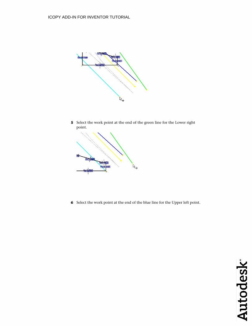
5 Select the work point at the end of the green line for the Lower right point.
6 Select the work point at the end of the blue line for the Upper left point.
ICOPY ADD-IN FOR INVENTOR TUTORIAL
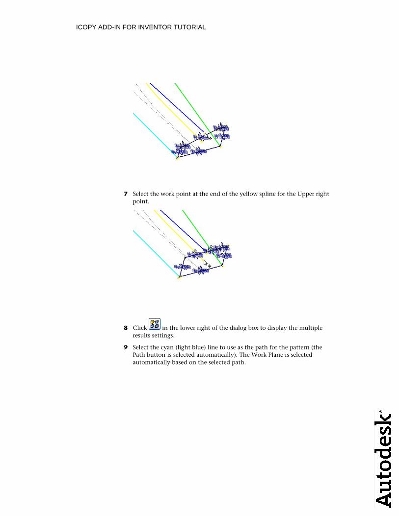
7 Select the work point at the end of the yellow spline for the Upper rightpoint.
8 Click in the lower right of the dialog box to display the multipleresults settings.
9 Select the cyan (light blue) line to use as the path for the pattern (thePath button is selected automatically). The Work Plane is selected automatically based on the selected path.
ICOPY ADD-IN FOR INVENTOR TUTORIAL
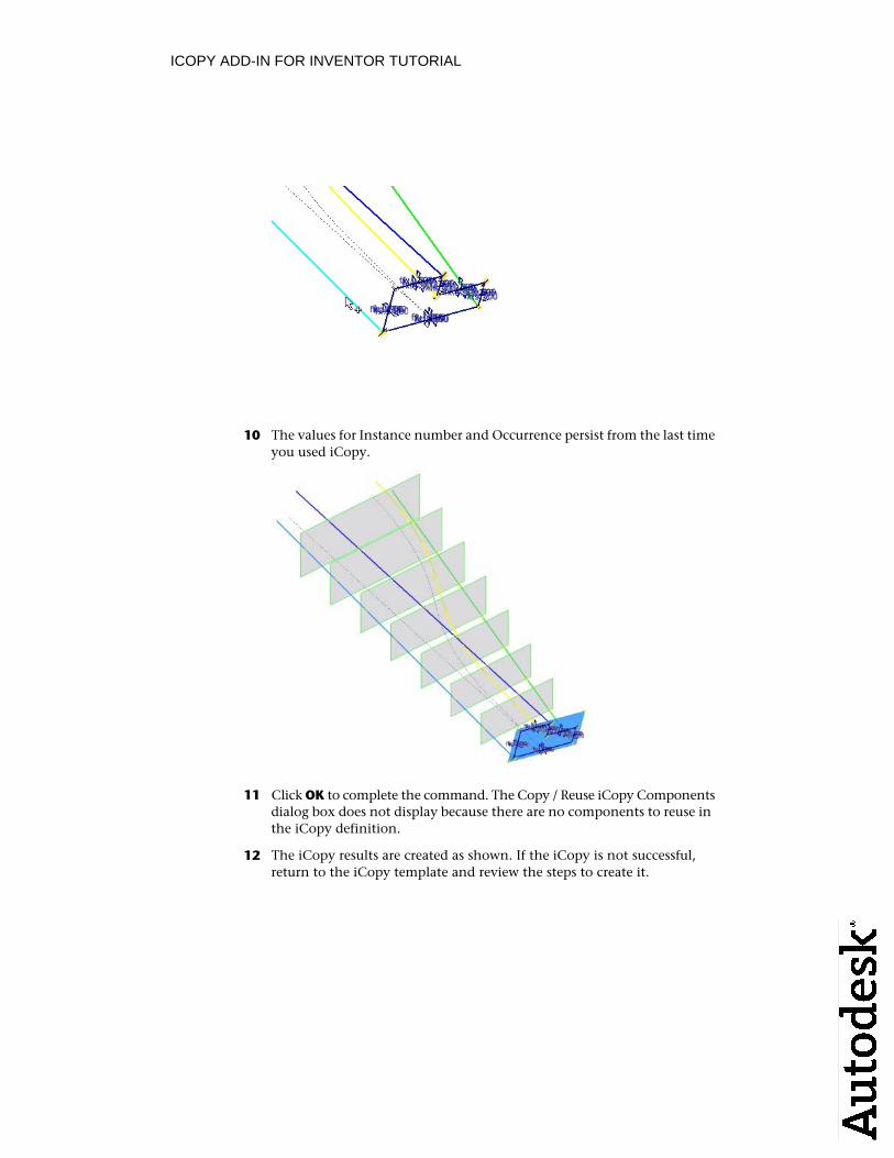
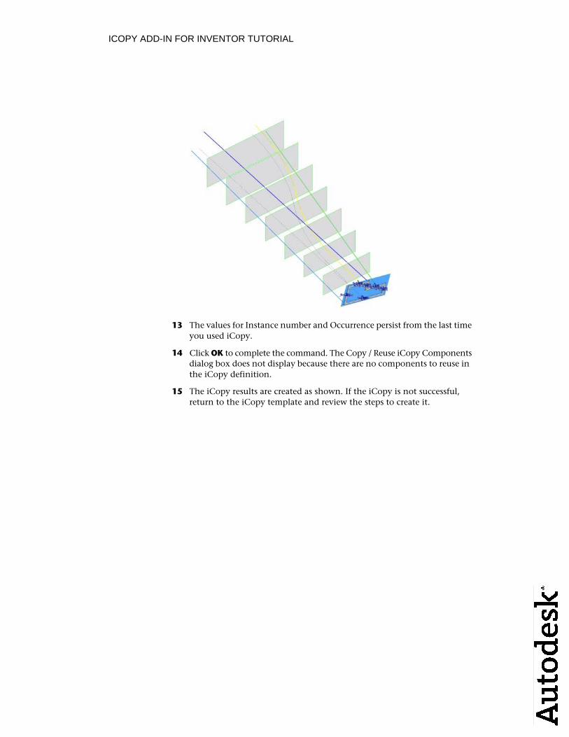
10 The values for Instance number and Occurrence persist from the last timeyou used iCopy.
11 Click OK to complete the command. The Copy / Reuse iCopy Components dialog box does not display because there are no components to reuse inthe iCopy definition.
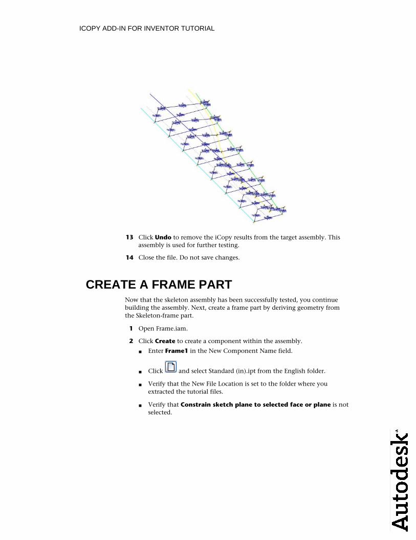
12 The iCopy results are created as shown. If the iCopy is not successful,return to the iCopy template and review the steps to create it.
ICOPY ADD-IN FOR INVENTOR TUTORIAL
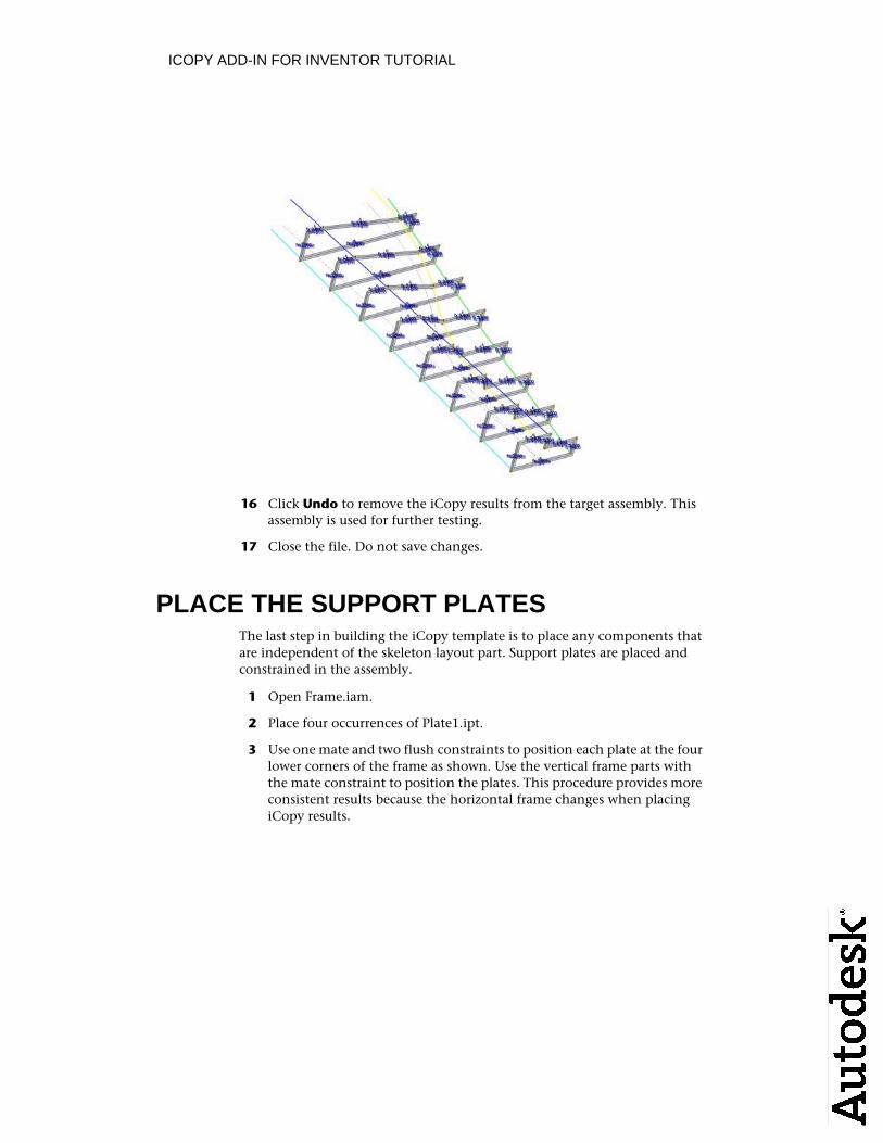
13 Click Undo to remove the iCopy results from the target assembly. Thisassembly is used for further testing.
14 Close the file. Do not save changes.
CREATE A FRAME PARTNow that the skeleton assembly has been successfully tested, you continuebuilding the assembly. Next, create a frame part by deriving geometry fromthe Skeleton-frame part.
1 Open Frame.iam.
2 Click Create to create a component within the assembly.
Enter Frame1 in the New Component Name field.■
Click and select Standard (in).ipt from the English folder. ■
Verify that the New File Location is set to the folder where you■extracted the tutorial files.
Verify that Constrain sketch plane to selected face or plane is not■selected.
ICOPY ADD-IN FOR INVENTOR TUTORIAL
Click OK. ■
3 In the browser, expand the Origin folder and select the XY Plane.
4 Exit the sketch and delete Sketch1. It is not needed for this component.
5 Start the Derive command.
6 In the Open dialog box, select Skeleton-frame.ipt and click Open.
7 Expand the Surface Bodies node. Set Srf1 and Srf6 to and all other
surfaces to .
8 Expand the Sketches node. Set Sketch2 to and all other sketches to
.
9 Expand the Work Geometry node. Set Work Plane5 to and all other
work planes to .
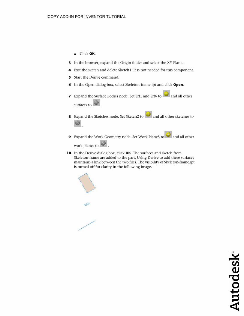
10 In the Derive dialog box, click OK. The surfaces and sketch from Skeleton-frame are added to the part. Using Derive to add these surfacesmaintains a link between the two files. The visibility of Skeleton-frame.ipt is turned off for clarity in the following image.
ICOPY ADD-IN FOR INVENTOR TUTORIAL
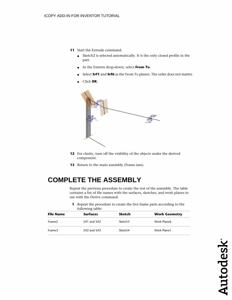
11 Start the Extrude command.
Sketch2 is selected automatically. It is the only closed profile in the■part.
In the Extents drop-down, select From To.■
Select Srf1 and Srf6 as the From To planes. The order does not matter.■
Click OK.■
12 For clarity, turn off the visibility of the objects under the derived component.
13 Return to the main assembly (Frame.iam).
COMPLETE THE ASSEMBLYRepeat the previous procedure to create the rest of the assembly. The tablecontains a list of file names with the surfaces, sketches, and work planes touse with the Derive command.
1 Repeat the procedure to create the five frame parts according to the following table:
File Name Surfaces Sketch Work Geometry
Frame2 Srf1 and Srf2 Sketch3 Work Plane6
Frame3 Srf2 and Srf3 Sketch4 Work Plane1
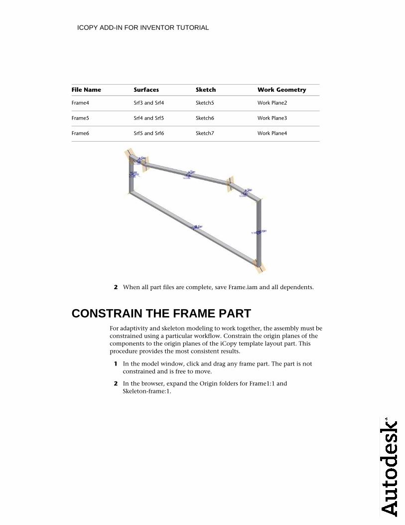
ICOPY ADD-IN FOR INVENTOR TUTORIAL
File Name Surfaces Sketch Work Geometry
Frame4 Srf3 and Srf4 Sketch5 Work Plane2
Frame5 Srf4 and Srf5 Sketch6 Work Plane3
Frame6 Srf5 and Srf6 Sketch7 Work Plane4
2 When all part files are complete, save Frame.iam and all dependents.
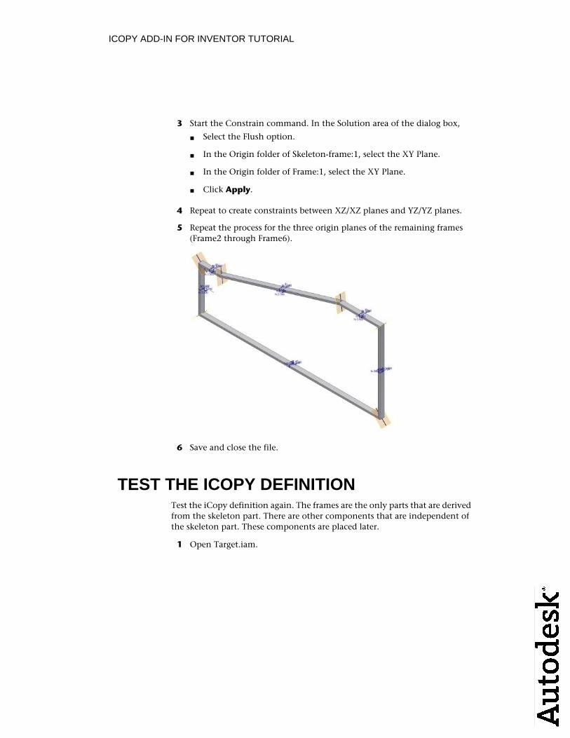
CONSTRAIN THE FRAME PARTFor adaptivity and skeleton modeling to work together, the assembly must beconstrained using a particular workflow. Constrain the origin planes of thecomponents to the origin planes of the iCopy template layout part. Thisprocedure provides the most consistent results.
1 In the model window, click and drag any frame part. The part is not constrained and is free to move.
2 In the browser, expand the Origin folders for Frame1:1 and Skeleton-frame:1.
ICOPY ADD-IN FOR INVENTOR TUTORIAL
3 Start the Constrain command. In the Solution area of the dialog box,
Select the Flush option.■
In the Origin folder of Skeleton-frame:1, select the XY Plane. ■
In the Origin folder of Frame:1, select the XY Plane.■
Click Apply.■
4 Repeat to create constraints between XZ/XZ planes and YZ/YZ planes.
5 Repeat the process for the three origin planes of the remaining frames(Frame2 through Frame6).
6 Save and close the file.
TEST THE ICOPY DEFINITIONTest the iCopy definition again. The frames are the only parts that are derivedfrom the skeleton part. There are other components that are independent ofthe skeleton part. These components are placed later.
1 Open Target.iam.
ICOPY ADD-IN FOR INVENTOR TUTORIAL
2 Start the iCopy command.
In the Ribbon: Assemble tab ➤ Component panel ➤ iCopy■
In the classic interface: Assembly panel ➤ iCopy■
3 Click and select Frame.iam. Click Open. The Constrain iCopy dialogbox displays.
4 Select the work point at the end of the cyan (light blue) line for the Lower left point.
5 Select the work point at the end of the green line for the Lower right point.
ICOPY ADD-IN FOR INVENTOR TUTORIAL
6 Select the work point at the end of the blue line for the Upper left point.
7 Select the work point at the end of the yellow spline for the Upper rightpoint.
8 In the Frame Height field, enter 5 in.
9 In the Frame Width field, enter 5 in.
ICOPY ADD-IN FOR INVENTOR TUTORIAL
10 In the lower right of the dialog box, click to display the multipleresults settings.
11 Select the cyan (light blue) line to use as the path for the pattern (the Path button is selected automatically).
12 The Work Plane is selected automatically based on the selected path.
ICOPY ADD-IN FOR INVENTOR TUTORIAL
13 The values for Instance number and Occurrence persist from the last timeyou used iCopy.
14 Click OK to complete the command. The Copy / Reuse iCopy Componentsdialog box does not display because there are no components to reuse inthe iCopy definition.
15 The iCopy results are created as shown. If the iCopy is not successful,return to the iCopy template and review the steps to create it.
ICOPY ADD-IN FOR INVENTOR TUTORIAL
16 Click Undo to remove the iCopy results from the target assembly. This assembly is used for further testing.
17 Close the file. Do not save changes.
PLACE THE SUPPORT PLATESThe last step in building the iCopy template is to place any components that are independent of the skeleton layout part. Support plates are placed and constrained in the assembly.
1 Open Frame.iam.
2 Place four occurrences of Plate1.ipt.
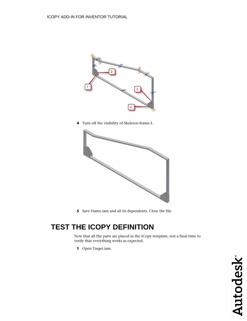
3 Use one mate and two flush constraints to position each plate at the four lower corners of the frame as shown. Use the vertical frame parts with the mate constraint to position the plates. This procedure provides more consistent results because the horizontal frame changes when placingiCopy results.
ICOPY ADD-IN FOR INVENTOR TUTORIAL
4 Turn off the visibility of Skeleton-frame:1.
5 Save Frame.iam and all its dependents. Close the file.
TEST THE ICOPY DEFINITIONNow that all the parts are placed in the iCopy template, test a final time toverify that everything works as expected.
1 Open Target.iam.
ICOPY ADD-IN FOR INVENTOR TUTORIAL
2 Start the iCopy command.
In the Ribbon: Assemble tab ➤ Component panel ➤ iCopy■
In the classic interface: Assembly panel ➤ iCopy■
3 Click and select Frame.iam. Click Open. The Constrain iCopy dialogbox displays.
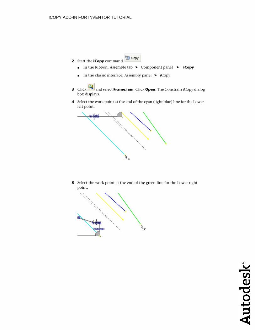
4 Select the work point at the end of the cyan (light blue) line for the Lower left point.
5 Select the work point at the end of the green line for the Lower right point.
ICOPY ADD-IN FOR INVENTOR TUTORIAL
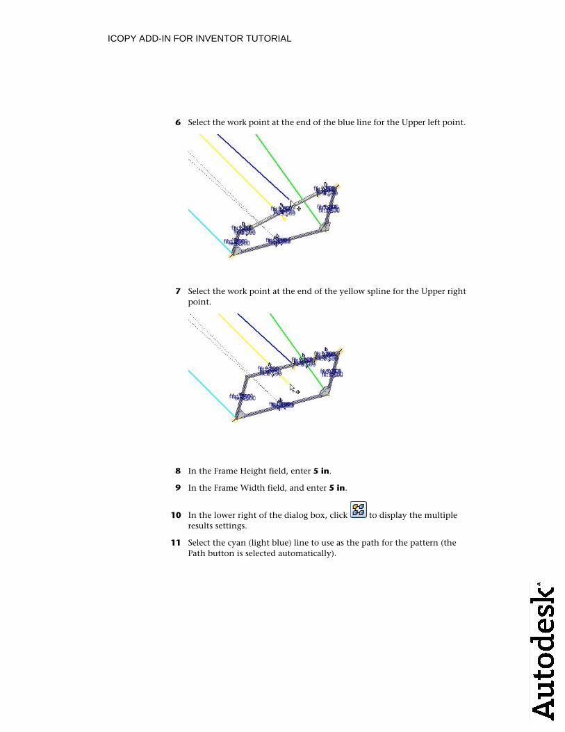
6 Select the work point at the end of the blue line for the Upper left point.
7 Select the work point at the end of the yellow spline for the Upper rightpoint.
8 In the Frame Height field, enter 5 in.
9 In the Frame Width field, and enter 5 in.
10 In the lower right of the dialog box, click to display the multipleresults settings.
11 Select the cyan (light blue) line to use as the path for the pattern (thePath button is selected automatically).
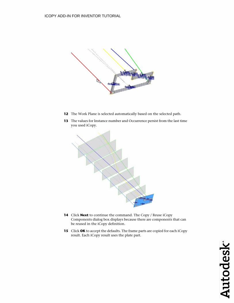
ICOPY ADD-IN FOR INVENTOR TUTORIAL
12 The Work Plane is selected automatically based on the selected path.
13 The values for Instance number and Occurrence persist from the last timeyou used iCopy.
14 Click Next to continue the command. The Copy / Reuse iCopyComponents dialog box displays because there are components that can be reused in the iCopy definition.
15 Click OK to accept the defaults. The frame parts are copied for each iCopy result. Each iCopy result uses the plate part.
ICOPY ADD-IN FOR INVENTOR TUTORIAL
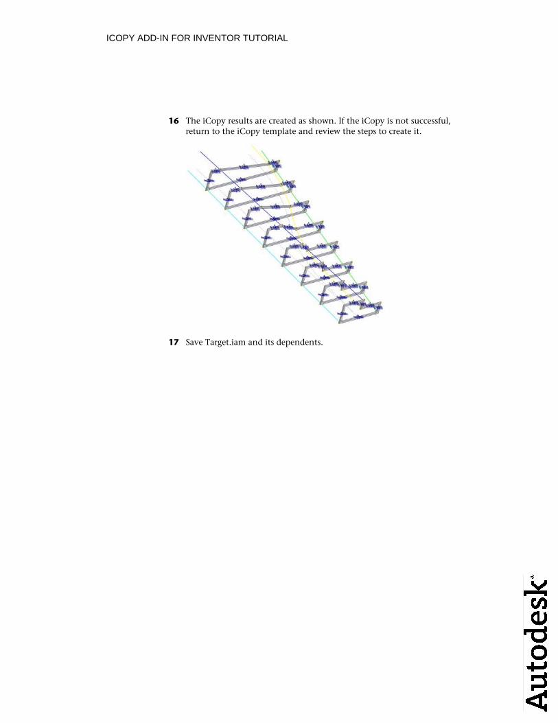
16 The iCopy results are created as shown. If the iCopy is not successful,return to the iCopy template and review the steps to create it.
17 Save Target.iam and its dependents.
ICOPY ADD-IN FOR INVENTOR TUTORIAL
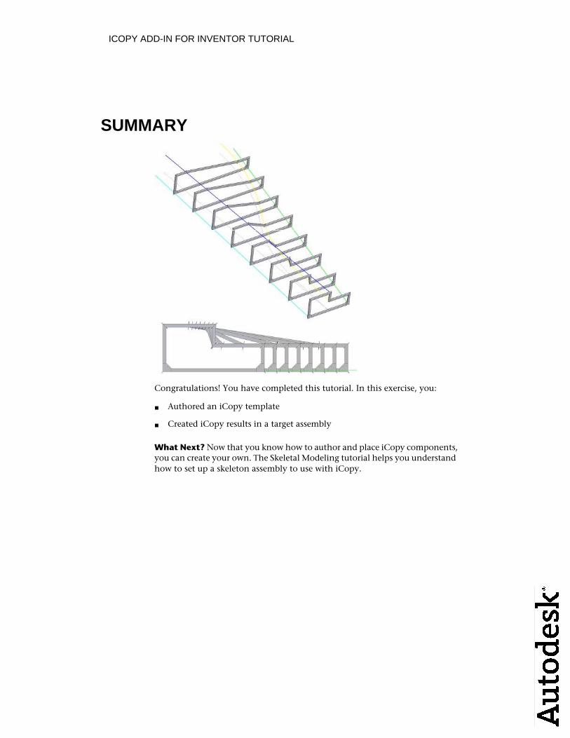
SUMMARY
Congratulations! You have completed this tutorial. In this exercise, you:
Authored an iCopy template■
Created iCopy results in a target assembly■
What Next? Now that you know how to author and place iCopy components, you can create your own. The Skeletal Modeling tutorial helps you understand how to set up a skeleton assembly to use with iCopy.

Recommended