1
HVAC, Water, and Other
Critical Utility Qualifications
IVT Validation Week
San Diego, CA
October 20th , 2016
Impact Assessment and Critical
Component Analysis

2
CONTACT INFORMATION
for Course Leader
Matthew Granger
Validation Technologies, Inc.
San Diego, CA
Office: 800-930-9222
Fax: 858-676-3677
Website: http://www.validation.org
3
PRESENTATION OVERVIEW
SUPPORT DOCUMENTATION
CONSTRUCTION QUALIFCATION
QUALIFICATION OF CRITICAL SYSTEMS
ESTABLISHING A ROUTINE
ENVIRONMENTAL PROGRAM
TRENDING AND DATA SUMMARY
“PROBLEM AREAS” - UTILITY SYSTEMS
REVALIDATION
4
PRESENTATION OVERVIEW –
Utility Systems
Purified Water Systems
Clean Steam
Compress Gases
HVAC Systems

5
Part 1
Documents to Support
Equipment Qualification
IQ/OQ Documentation
IQPQ
OQ
DQ
OQ
CQ
VC
PV
PQ
IQ
6
Support Documents
• The User Requirements Specification (URS)
• Design Specifications
• Functional Specifications
• Purchases Requisitions
• Turn-Over- Packages
• Vendor Manuals
• P&IDs
• Manuals
• Commissioning
• FAT/SAT
• Change Management

7
Part 2
Critical Utility Project
Strategy
Plan the Work and Work the Plan
8
PROGRAMS REQUIRED FOR FACILITY & CRITICAL
UTILITIES QUALIFICATIONS
• PROJECT DESIGN SPECIFICATION
• VALIDATION MASTER PLAN
• PROJECT SCHEDULE
• CONSTRUCTION QUALIFICATION PACKAGES
• INSTALLATION QUALIFICATION PROTOCOLS
• FACILITY STARTUP/COMMISSIONING
• STANDARD OPERATING PROCEDURES
• CALIBRATION PROGRAM
• OPERATIONAL QUALIFICATION PROTOCOLS
• ANALYTICAL METHODS VALIDATED
• PERFORMANCE QUALIFICATION
9
PROJECT SCHEDULE
• DEFINED CRITICAL PATHS
• CONSTRUCTION ACTIVITIES
• COLLECTION OF CONSTURCTION QUALIFCATION CQ
DATA
• DEVELOPMENT OF PROTOCOL FORMAT
• WRITE IQ & OQ PROTOCOLS
• EQUIPMENT INSTALLATION ACTIVITIES
• EXECUTION OF IQ PROTOCOLS
• COMMISSION OF SYSTEM
• EXECUTION OF OQ PROTOCOLS
• ANALYTICAL METHODS VALIDATED
• WRITE & EXECUTE PERFORMANCE QUALIFICATIONS

10
Part 3
Commissioning and
Construction
Program
11
Good Engineering Practice (GEP)
• GEP project scope
– Documentation
– Organization and Communication
– Requirements Phase
– Design Phase
– Construction Phase
– Project Controls
– Commissioning and Qualification
– Project Closeout and Turnover
12
Commissioning Plan
• Commissioning Plan should contain the following deliverables: (Direct Impact Systems)
– Commissioning Plan
– Commissioning Schedule
– Commissioning Budget
– Overall Test Plan
– Factory Acceptance Test/Report
– Site Acceptance Test/Report
– Inspection Plan/Report
– Functional Test/Report
– System Test Summary Reports
– Commissioning Summary Reports
13
System Impact and Component
Criticality
• Indirect Impact or No Impact system are comprised of non-critical components only
• Direct Impact system have both critical and non-critical components. (Components deemed non-critical may be managed within Good Engineering Practices (GEP) alone)
• Design for Impact reduces the scope of the system and components to Qualification Practices allowing appropriate focus on the components presenting a risk to product quality
• Should an Indirect Impact or No Impact system incorporate one or more critical components, either the system has been mis-classified or the component was wrongly assessed.
14
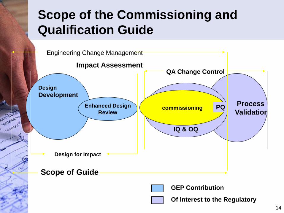
Scope of the Commissioning and
Qualification Guide
Design
Development
Engineering Change Management
Enhanced Design
Review
Scope of Guide
Process
Validation
IQ & OQ
commissioning PQ
Design for Impact
Impact AssessmentQA Change Control
GEP Contribution
Of Interest to the Regulatory
15
Impact Assessment
• “Direct Impact” Systems are expected to have an impact on product quality
• Indirect Impact systems are not expect to have an impact on product.
– Both types of systems will require commissioning; however, the “Direct Impact” system will be subject to qualification practices to meet additional regulatory requirements of the FDA and other regulatory authorities
– System Impact Assessment Form Direct HVAC System Template Part 1.doc
16
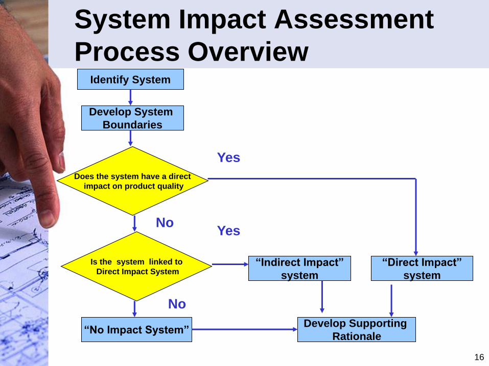
System Impact Assessment
Process OverviewIdentify System
Develop System
Boundaries
Does the system have a direct
impact on product quality
Is the system linked to
Direct Impact System
“No Impact System”
“Indirect Impact”
system
“Direct Impact”
system
Develop Supporting
Rationale
Yes
YesNo
No
17
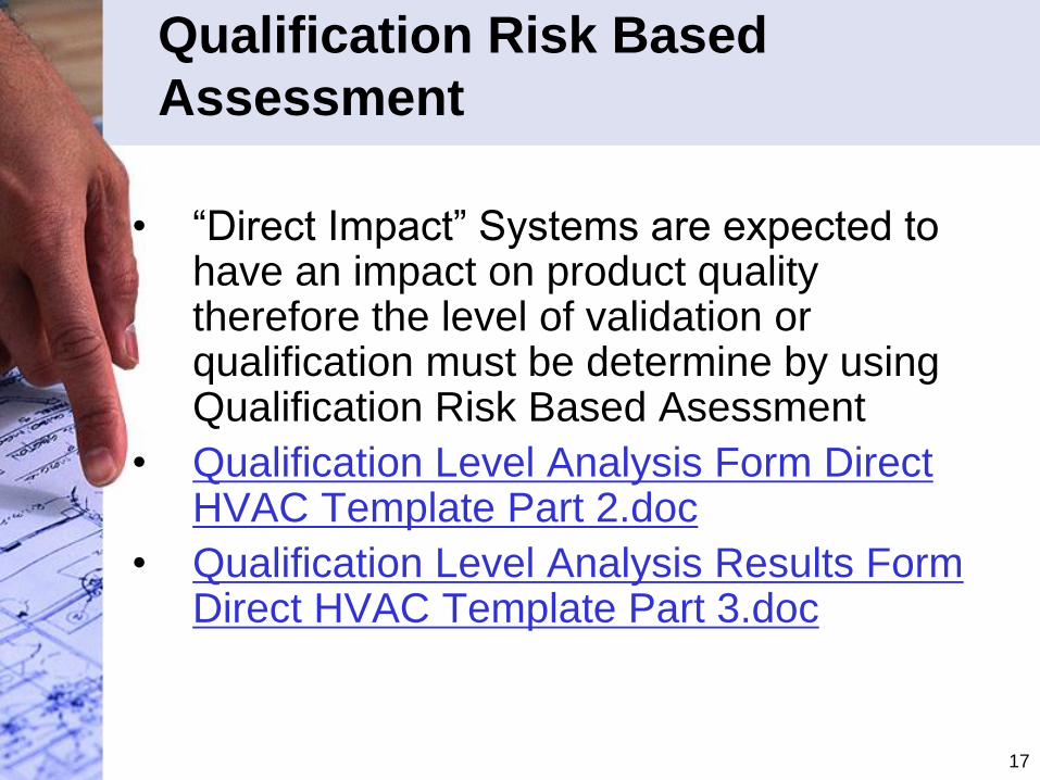
Qualification Risk Based
Assessment
• “Direct Impact” Systems are expected to have an impact on product quality therefore the level of validation or qualification must be determine by using Qualification Risk Based Asessment
• Qualification Level Analysis Form Direct HVAC Template Part 2.doc
• Qualification Level Analysis Results Form Direct HVAC Template Part 3.doc
18
Component Criticality
Assessment Process
• The components within “Direct Impact”,
Indirect Impact” and in some cases “No
Impact” systems should be assessed for
criticality.
• Must have updated Piping and Instrument
Drawings (P&IDs)
19
System Impact and Component
Criticality• Indirect Impact or No Impact system are comprised
of non-critical components only
• Direct Impact system have both critical and non-critical components. (Components deemed non-critical may be managed within Good Engineering Practices (GEP) alone)
• Design for Impact reduces the scope of the system and components to Qualification Practices allowing appropriate focus on the components presenting a risk to product quality
• Should an Indirect Impact or No Impact system incorporate one or more critical components, either the system has been mis-classified or the component was wrongly assessed.
• Critical Component Analysis Form Direct HVAC Template 4.doc
20
Part 4
Qualification of
Critical Utilities
Systems
Design, Construct, Commission then
Qualify
21
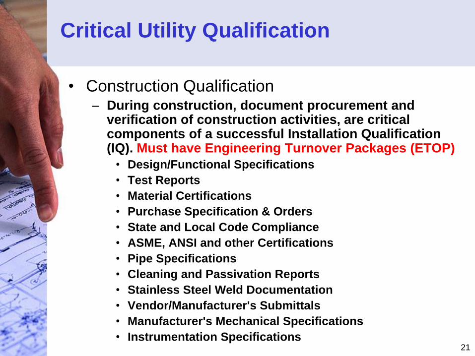
Critical Utility Qualification
• Construction Qualification– During construction, document procurement and
verification of construction activities, are critical components of a successful Installation Qualification (IQ). Must have Engineering Turnover Packages (ETOP)
• Design/Functional Specifications
• Test Reports
• Material Certifications
• Purchase Specification & Orders
• State and Local Code Compliance
• ASME, ANSI and other Certifications
• Pipe Specifications
• Cleaning and Passivation Reports
• Stainless Steel Weld Documentation
• Vendor/Manufacturer's Submittals
• Manufacturer's Mechanical Specifications
• Instrumentation Specifications
22
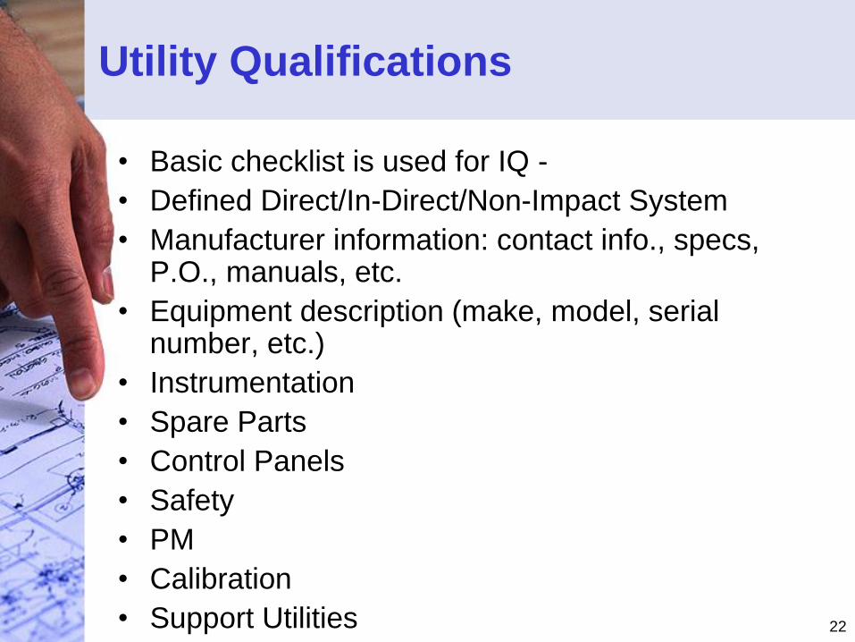
Utility Qualifications
• Basic checklist is used for IQ -
• Defined Direct/In-Direct/Non-Impact System
• Manufacturer information: contact info., specs, P.O., manuals, etc.
• Equipment description (make, model, serial number, etc.)
• Instrumentation
• Spare Parts
• Control Panels
• Safety
• PM
• Calibration
• Support Utilities
23
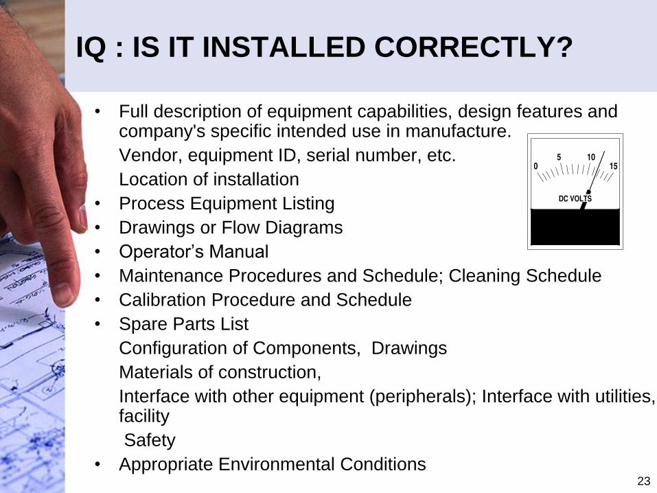
IQ : IS IT INSTALLED CORRECTLY?
• Full description of equipment capabilities, design features and company's specific intended use in manufacture.
• Vendor, equipment ID, serial number, etc.
• Location of installation
• Process Equipment Listing
• Drawings or Flow Diagrams
• Operator’s Manual
• Maintenance Procedures and Schedule; Cleaning Schedule
• Calibration Procedure and Schedule
• Spare Parts List
• Configuration of Components, Drawings
• Materials of construction,
• Interface with other equipment (peripherals); Interface with utilities, facility
• Safety
• Appropriate Environmental Conditions
24
Critical Utility Qualification
• Installation Qualification - is a documented plan
for the performance of inspections and the
collection of documentation to verify static
attributes of a system. – System Location
– System Description
– Major Components Identification Summary
– Field Inspection Report- Comparison of Actual to
Specified
– Instrumentation List
– Spare Parts List
– Documentation/Drawings List
25
Utility Qualifications
• Operational Qualification - Does the
equipment function as intended?
• Challenge the process (equipment)
parameters under worst case testing. This
is where you determine the degree of
“robustness” with the equipment.
• Objective, Scope, Description, etc.
• Operational testing
• Acceptance criteria
• Deviations (Excursions, etc.)
• Approvals
26
Critical Utility Qualification
• Operational Qualification (OQ) - is a documented plan for the
performance of inspections and tests to verify specified
dynamic attributes of a system.
– SOP Review
– Calibration Review
– Test of Alarms
– Test of Controls
– Test of Interlocks
– Start Up/Shutdown Sequence Verifications
– Normal Run Mode Verification - Monitoring Applicable
Indications:
• Pressure
• Temperature
• Time
• Resistivity/Conductivity
• Flow
• pH
27
PERFORMANCE QUALIFICATION
PROTOCOL FOR CRITICAL UTILITIES
• OBJECTIVE
• IDENTIFICATION
• SYSTEM PERFORMANCE DESCRIPTION
• REFERENCES
• RESPONSIBILITIES
• PROCEDURE
• ACCEPTANCE CRITERIA
• PERFORMANCE QUALIFICATION TEST
• COMMENTS
• DEVIATION/EXCEPTIONAL CONDITION
• ATTACHMENTS
28
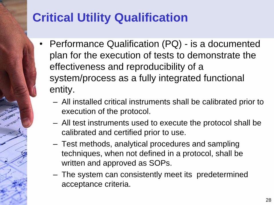
Critical Utility Qualification
• Performance Qualification (PQ) - is a documented
plan for the execution of tests to demonstrate the
effectiveness and reproducibility of a
system/process as a fully integrated functional
entity.
– All installed critical instruments shall be calibrated prior to
execution of the protocol.
– All test instruments used to execute the protocol shall be
calibrated and certified prior to use.
– Test methods, analytical procedures and sampling
techniques, when not defined in a protocol, shall be
written and approved as SOPs.
– The system can consistently meet its predetermined
acceptance criteria.
29
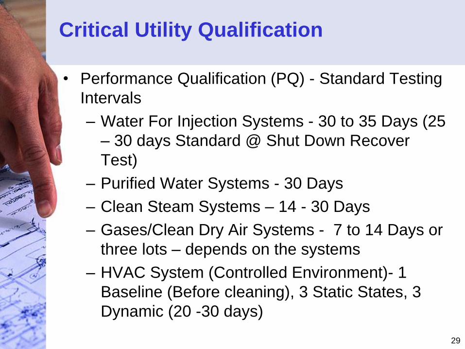
Critical Utility Qualification
• Performance Qualification (PQ) - Standard Testing
Intervals
– Water For Injection Systems - 30 to 35 Days (25
– 30 days Standard @ Shut Down Recover
Test)
– Purified Water Systems - 30 Days
– Clean Steam Systems – 14 - 30 Days
– Gases/Clean Dry Air Systems - 7 to 14 Days or
three lots – depends on the systems
– HVAC System (Controlled Environment)- 1
Baseline (Before cleaning), 3 Static States, 3
Dynamic (20 -30 days)
30
Part 5
Validation of Purified
Water Systems
Purified Water is used in Aspect of GMP
Manufacturing Operations
31
Water Usage in
Pharmaceutical Production
• Water Requirements
– Potable - EPA
– USP Purified – different types
– USP Water For Injection
32
Validation of Critical Water Systems
• FDA Requirements: Phase 1
• All water systems should have
documentation containing a system
description and accurate drawing.
• The drawing needs to show all equipment in
the systems from water input to points of
use. It should also show all sampling points
and their designations.
33
Validation of Critical Water Systems
• FDA Requirements: Phase 1
• After all the equipment and piping has
been verified as installed correctly and
working as specified, the initial phase of
the water system validation can begin.
34
Validation of Critical Water Systems
• FDA Requirements: Phase 1
• During the initial phase the operational
parameters and cleaning/sanitation
procedures and frequencies will be
developed. Sampling should be daily after
each step in the purification process and at
each point of use for two to four weeks.
35
Validation of Critical Water Systems
• FDA Requirements: Phase 1
– The sampling procedures for point of use should
reflect how they are taken, e.g. use of hose, and
time for flushing. At the end of the two (2) or
four (4) weeks the firm should have developed
its SOPs for operation and maintenance of the
water system.
36
Validation of Critical Water Systems
• FDA Requirements: Phase 2
• The second phase of the water system
validation is to demonstrate that the system
will consistently produce the desired water
quality when operated in conformance with
SOPs.
37
Validation of Critical Water Systems
• FDA Requirements: Phase 2
• The sampling is performed as in the initial
phase and for the same period . At the end
of this phase the data should demonstrate
that the system will consistently produce the
desired quality of water.
38
Validation of Critical Water Systems
• FDA Requirements: Phase 3
• The third phase of validation is designed to
demonstrate that when the water system is
operated, in accordance with the SOPs,
over a long period of time it will consistently
produce water of desired quality.
39
Validation of Critical Water Systems
• FDA Requirements: Phase 3
• Any variations in quality of the feedwater,
that could affect the operation and ultimately
the water quality, will be noticed during this
phase of the validation.
40
Validation of Critical Water Systems
• FDA Requirements: Phase 3
• Sampling is performed according to routine
procedures and frequencies.
• For Water for Injection systems samples
should be taken daily from a minimum of
one point of use, with all points of use
tested weekly.
41
Validation of Critical Water Systems
• FDA Requirements: Phase 3
• The validation of the water system is
completed when the firm has collected data
for a full year.
• The FDA states that “while the above
validation scheme is not the only way a
system can be validated, it contains the
necessary elements for validation of a water
system.”
42
Validation of Critical Water Systems
• FDA Requirements: Phase 3
• First, there must be data to support the
SOPs.
• Second, there must be data demonstrating
that the SOPs are valid and that the system
is capable of consistently producing water
that meets the desired specifications.
43
Validation of Critical Water Systems
• FDA Requirements: Phase 3
• Finally, there must be data to demonstrate
that seasonal variations in the feedwater do
not adversely affect the operation of the
system or the water quality. This last part of
the validation is the compilation of the data,
with any conclusions into the final report.
44
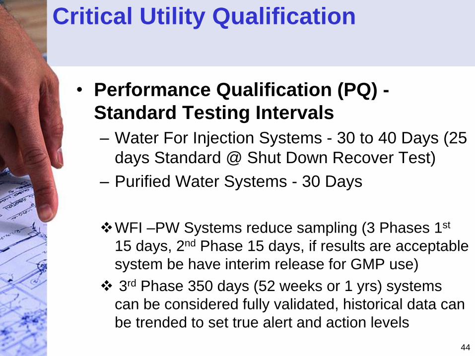
Critical Utility Qualification
• Performance Qualification (PQ) -
Standard Testing Intervals
– Water For Injection Systems - 30 to 40 Days (25
days Standard @ Shut Down Recover Test)
– Purified Water Systems - 30 Days
WFI –PW Systems reduce sampling (3 Phases 1st
15 days, 2nd Phase 15 days, if results are acceptable
system be have interim release for GMP use)
3rd Phase 350 days (52 weeks or 1 yrs) systems
can be considered fully validated, historical data can
be trended to set true alert and action levels
45
ESTABLISHING ENVIRONMENTAL
MONITORING PROGRAM
• When establishing a routine
environmental monitoring program, the
PQ study data should be the starting point
for determining the sampling sites and
testing frequencies.

46
PURIFIED WATER SYSTEMS
ENVIRONMENTAL MONITORING PROGRAM
• Sample Site and Frequencies Determination
– For Water for Injection systems samples
should be taken daily from all point of use.
– For Purified Water systems samples should
be taken daily from a minimum of one point
of use, with all points of use tested within a
week.
47
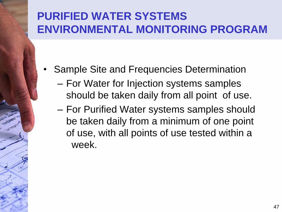
PURIFIED WATER SYSTEMS
ENVIRONMENTAL MONITORING PROGRAM
• Sample Site and Frequencies Determination
– For Water for Injection systems samples
should be taken daily from all point of use.
– For Purified Water systems samples should
be taken daily from a minimum of one point
of use, with all points of use tested within a
week.
48
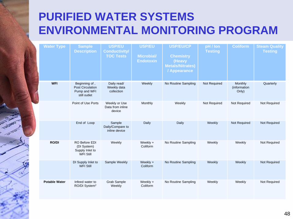
PURIFIED WATER SYSTEMS
ENVIRONMENTAL MONITORING PROGRAM
Water Type Sample
Description
USP/EU
Conductivity/
TOC Tests
USP/EU
Microbial/
Endotoxin
USP/EU/CP
Chemistry
(Heavy
Metals/Nitrates)
/ Appearance
pH / Ion
Testing
Coliform Steam Quality
Testing
WFI Beginning of ,
Post Circulation
Pump and WFI
still outlet
Daily read/
Weekly data
collection
Weekly No Routine Sampling Not Required Monthly
(information
Only)
Quarterly
Point of Use Ports Weekly or Use
Data from inline
device
Monthly Weekly Not Required Not Required Not Required
End of Loop Sample
Daily/Compare to
inline device
Daily Daily Weekly Not Required Not Required
RO/DI RO Before EDI
(DI System)
Supply Inlet to
WFI Still
Weekly Weekly +
Coliform
No Routine Sampling Weekly Weekly Not Required
DI Supply Inlet to
WFI Still
Sample Weekly Weekly +
Coliform
No Routine Sampling Weekly Weekly Not Required
Potable Water Infeed water to
RO/DI System2
Grab Sample
Weekly
Weekly +
Coliform
No Routine Sampling Weekly Weekly Not Required
49
Part 5
Validation of Clean
System Systems
Clean Steam is used in certain aspects of
GMP Manufacturing Operations
50
Clean Steam Usage in
Pharmaceutical Production
• Clean Steam Requirements
– Steam-In-Place (SIP) – tanks, transfer
lines, bioreactors, etc.
– Sterilization Process - autoclaves
51
Clean Steam Usage in
Pharmaceutical Production
• Clean Steam Validation
Requirements
– URS
– DQ
– IQ, OQ & PQ

52
Clean Steam Usage in
Pharmaceutical Production
• Clean Steam Design
– Skid includes Clean Steam Generator
– Distribution System
– Points of Use (Traps) – Autoclave,
Reactors, etc.
53
Clean Steam Usage in
Pharmaceutical Production
• PQ Requirements
– Typically 7 – 14 days depending on
the complexity of the system
54
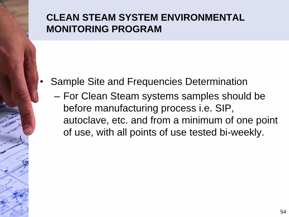
CLEAN STEAM SYSTEM ENVIRONMENTAL
MONITORING PROGRAM
• Sample Site and Frequencies Determination
– For Clean Steam systems samples should be
before manufacturing process i.e. SIP,
autoclave, etc. and from a minimum of one point
of use, with all points of use tested bi-weekly.
55
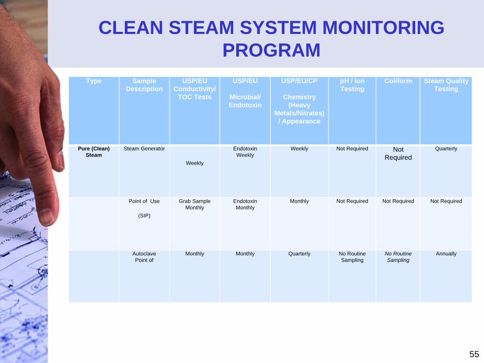
CLEAN STEAM SYSTEM MONITORING
PROGRAM
Type Sample
Description
USP/EU
Conductivity/
TOC Tests
USP/EU
Microbial/
Endotoxin
USP/EU/CP
Chemistry
(Heavy
Metals/Nitrates)
/ Appearance
pH / Ion
Testing
Coliform Steam Quality
Testing
Pure (Clean)
Steam
Steam Generator
Weekly
Endotoxin
Weekly
Weekly Not Required Not
Required
Quarterly
Point of Use
(SIP)
Grab Sample
Monthly
Endotoxin
Monthly
Monthly Not Required Not Required Not Required
Autoclave
Point of
Monthly Monthly Quarterly No Routine
Sampling
No Routine
Sampling
Annually
56
Part 5
Validation of
Compress Gas
Systems
There are many different types of gases
used in a GMP manufacturing operation
57
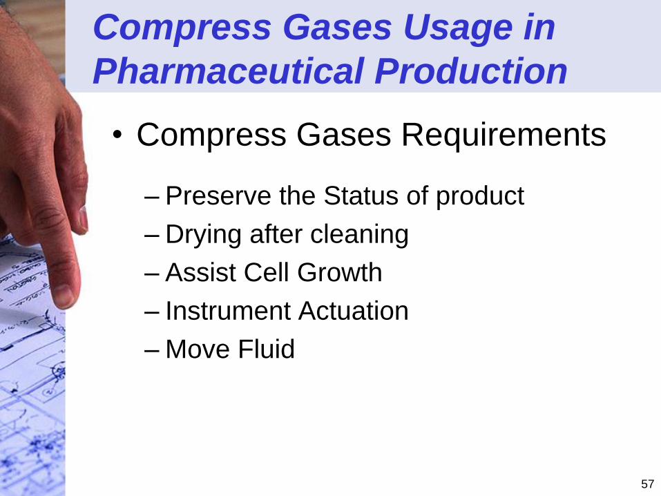
Compress Gases Usage in
Pharmaceutical Production
• Compress Gases Requirements
– Preserve the Status of product
– Drying after cleaning
– Assist Cell Growth
– Instrument Actuation
– Move Fluid
58
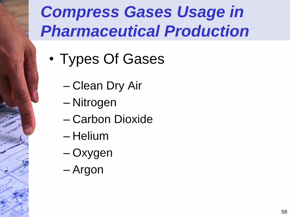
Compress Gases Usage in
Pharmaceutical Production
• Types Of Gases
– Clean Dry Air
– Nitrogen
– Carbon Dioxide
– Helium
– Oxygen
– Argon
59
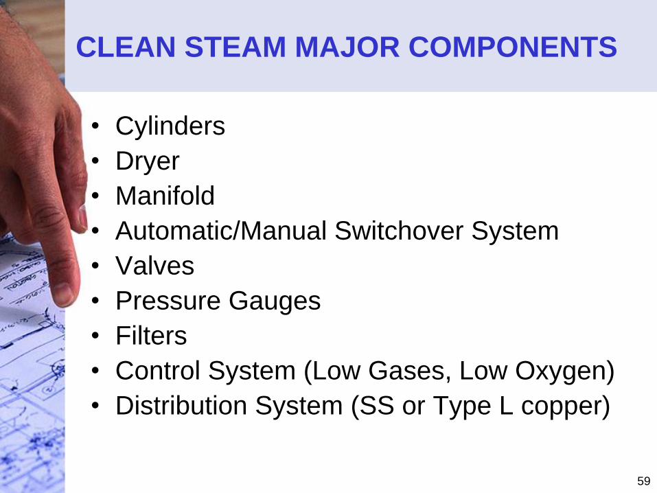
CLEAN STEAM MAJOR COMPONENTS
• Cylinders
• Dryer
• Manifold
• Automatic/Manual Switchover System
• Valves
• Pressure Gauges
• Filters
• Control System (Low Gases, Low Oxygen)
• Distribution System (SS or Type L copper)
60
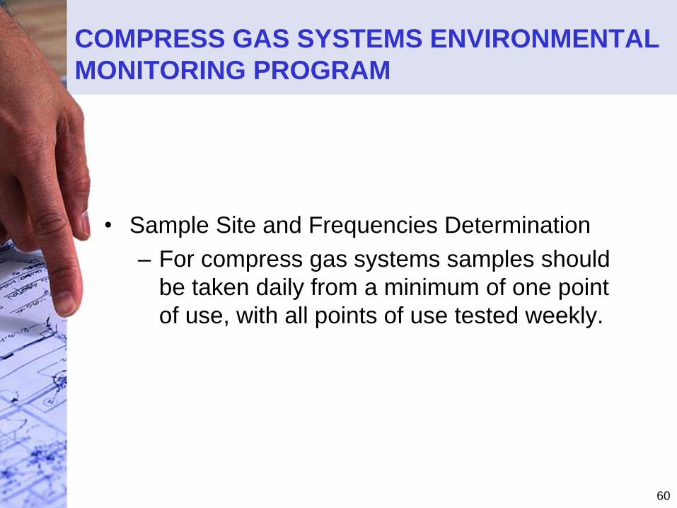
COMPRESS GAS SYSTEMS ENVIRONMENTAL
MONITORING PROGRAM
• Sample Site and Frequencies Determination
– For compress gas systems samples should
be taken daily from a minimum of one point
of use, with all points of use tested weekly.
61
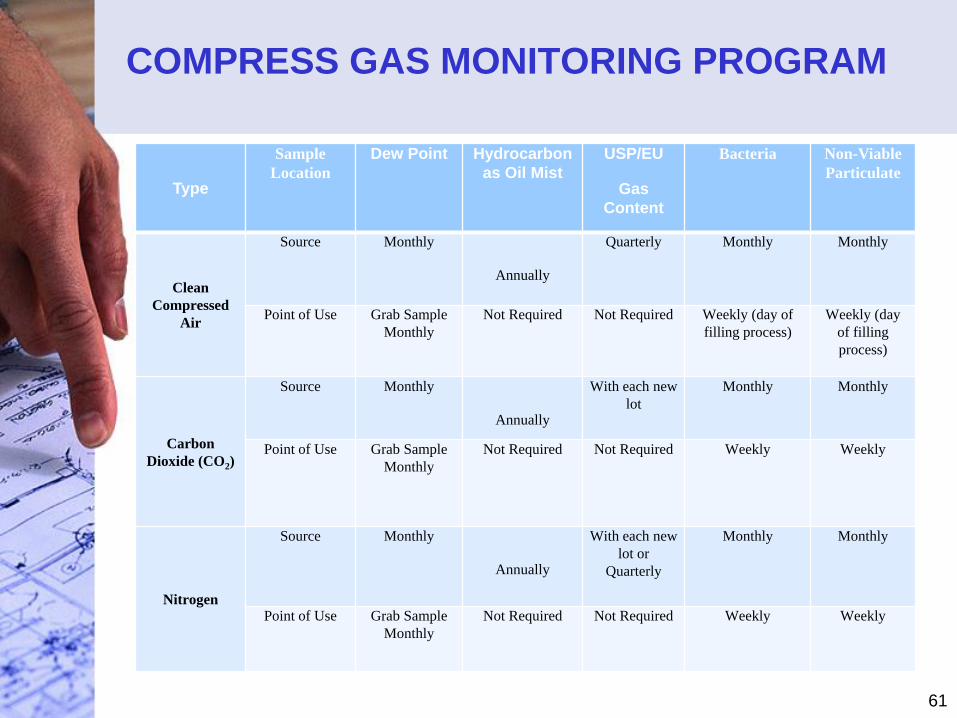
COMPRESS GAS MONITORING PROGRAM
Type
Sample
Location
Dew Point Hydrocarbon
as Oil Mist
USP/EU
Gas
Content
Bacteria Non-Viable
Particulate
Clean
Compressed
Air
Source Monthly
Annually
Quarterly Monthly Monthly
Point of Use Grab Sample
Monthly
Not Required Not Required Weekly (day of
filling process)
Weekly (day
of filling
process)
Carbon
Dioxide (CO2)
Source Monthly
Annually
With each new
lot
Monthly Monthly
Point of Use Grab Sample
Monthly
Not Required Not Required Weekly Weekly
Nitrogen
Source Monthly
Annually
With each new
lot or
Quarterly
Monthly Monthly
Point of Use Grab Sample
Monthly
Not Required Not Required Weekly Weekly
62
Part 6
Validation of HVAC
Systems
HVAC is used in Aspect of GMP
Manufacturing Operations
63
Clean Room Standards
• This ISO committee will produce 10 new standards documents that relate to cleanrooms or clean zones (described below). The nine standards have been published: ISO 14644-1 and -9.
– The first document, ISO 14644-1, Cleanrooms and associated controlled environments Part 1: Classification of airborne particulates has been released as a final document.
– The second document, ISO 14644-2, Cleanrooms and associated controlled environments Part 2: Testing and monitoring to prove continued compliance with ISO 14644-1; has been released as a final document.
64
Clean Room Certification
• Clean Room Certification Testing– Differential Air Flow
– Humidity/Temperature
– Supply Air Volume/Room Air Change Rate
– Room Differential Pressures
– DOP Test of HEPA Filters
– Room Non-Viable Particulate Counts
– Light Levels
– Noise Levels
– Recovery Time
– Unidirectional and Parallelism
– Enclosure Induction
65
Clean Room Certification
• Clean Room Certification Testing– Establishing of Sampling location (ISO 14644-1
Annex B)
• Derive the minimum number of sampling point
locations from equation:
– New ISO 14644-1 have been updated are in draft includes
table.
66
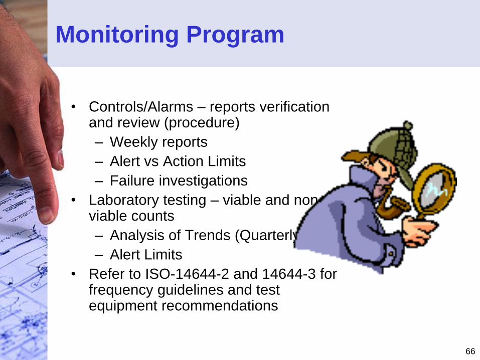
Monitoring Program
• Controls/Alarms – reports verification and review (procedure)
– Weekly reports
– Alert vs Action Limits
– Failure investigations
• Laboratory testing – viable and non-viable counts
– Analysis of Trends (Quarterly)
– Alert Limits
• Refer to ISO-14644-2 and 14644-3 for frequency guidelines and test equipment recommendations
67
HVAC SYSTEMS ENVIRONMENTAL
MONITORING PROGRAM
• Sample Site and Frequencies Determination– Would the act of sampling at a given site disturb the
environment sufficiently to cause erroneous data or possibly cause the product to be contaminated?
– At which site would the potential of microbial contamination most likely affect product quality adversely?
– During the PQ study which sites were highest in microbial contaminates.
– What sites would be the most difficult to clean?
– Should site selection involve statistical design or should it be based on a grid profile?
– How often is a particular area or process used?
68
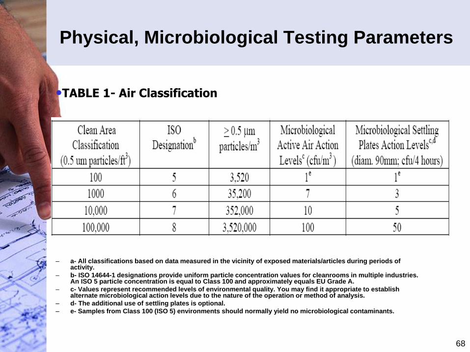
Physical, Microbiological Testing Parameters
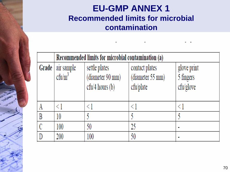
– a- All classifications based on data measured in the vicinity of exposed materials/articles during periods of activity.
– b- ISO 14644-1 designations provide uniform particle concentration values for cleanrooms in multiple industries. An ISO 5 particle concentration is equal to Class 100 and approximately equals EU Grade A.
– c- Values represent recommended levels of environmental quality. You may find it appropriate to establish alternate microbiological action levels due to the nature of the operation or method of analysis.
– d- The additional use of settling plates is optional.
– e- Samples from Class 100 (ISO 5) environments should normally yield no microbiological contaminants.
•TABLE 1- Air Classification
69
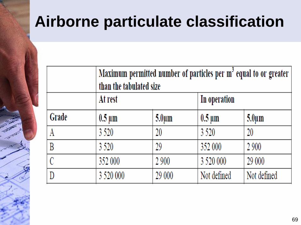
Airborne particulate classification
70
EU-GMP ANNEX 1Recommended limits for microbial
contamination
71
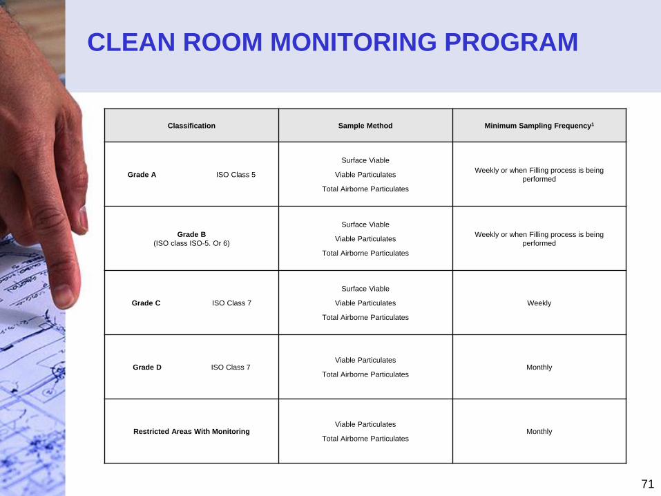
CLEAN ROOM MONITORING PROGRAM
Classification Sample Method Minimum Sampling Frequency1
Grade A ISO Class 5
Surface Viable
Viable Particulates
Total Airborne Particulates
Weekly or when Filling process is being
performed
Grade B
(ISO class ISO-5. Or 6)
Surface Viable
Viable Particulates
Total Airborne Particulates
Weekly or when Filling process is being
performed
Grade C ISO Class 7
Surface Viable
Viable Particulates
Total Airborne Particulates
Weekly
Grade D ISO Class 7Viable Particulates
Total Airborne ParticulatesMonthly
Restricted Areas With Monitoring Viable Particulates
Total Airborne ParticulatesMonthly
72
Part 7
Maintenance
Program for Critical
Utility Systems
Maintenance of Critical Utility Systems
insure the life cycle approach to validation
73
CHANGE CONTROL PROGRAM
• Change Control Program (CCP) Maintains Utility Systems Life Cycle Approach To Validations
• Supports Revalidation Activities.
• Should have established Change Control Program which includes critical review process when changes are made to any critical utility system.
• CCP should include changes made and extent of validation required.
74
REVALIDATION PROGRAM
• Annual review of change control forms for each
critical utility system.
• Annual review of the maintenance and cleaning
logs associated with each critical utility system.
• Annual review of routine environmental monitoring data.
• Annual abbreviated PQ study may be required under certain conditions.
75
VALIDATION MAINTENANCE PROGRAM
(CONT.)
• Validation Maintenance Requirements:
1. System Specific Operation, Maintenance, Cleaning Procedures
2. System Specific Routine Monitoring Programs
3. Trend Analysis
4. Calibration Program
5. Preventive Maintenance Program
6. Change Control Program
7. QA Auditing
8. Deviation /Investigation Reporting
9. Revalidation Program
76
“PROBLEM AREAS” - UTILITY SYSTEMS
• No diagrams provided, no narratives
• Diagrams not detailed
• Validation data summaries insufficient
– monitoring too infrequent
– sampling plan inadequate
– monitoring not performed during production
– inappropriate parameter tested
– validation period too short
– inadequate alert and action limits and specs

Thank You
Question and Answers
Validation Technologies Inc. 77
Recommended