Tower UPS 10kVA~40kVA User Manual I
Preface
Preface Usage The manual contains information on installing, using, operation and maintenance of the Tower UPS. Please carefully read this manual prior to installation. Users Technical Support Engineer Maintenance Engineer Note Our company is providing a full range of technical support and services. Customer can contact our local office or customer service center for help. The manual will update irregularly, due to the product upgrading or other reasons. Unless otherwise agreed,the manual is only used as guide for users and any statements or information contained in this manual make no warranty expressed or implied.
II Tower UPS 10kVA~40kVA User Manual
Contents
Contents 1. Safety Precautions ......................................................................................................................... 1
Safety Message Definition ........................................................................................................ 1 Warning Label ........................................................................................................................... 1 Safety Instruction ...................................................................................................................... 1 Move & Install .......................................................................................................................... 1 Debug & Operate ...................................................................................................................... 2 Maintenance & Replacement .................................................................................................... 2 Battery Safety ........................................................................................................................... 3 Disposal .................................................................................................................................... 4
2. Product Introduction ..................................................................................................................... 5 2.1 System Configuration ......................................................................................................... 5 2.3 Operation Mode .................................................................................................................. 5
2.3.1 Normal Mode ........................................................................................................... 5
2.3.2 Battery Mode ........................................................................................................... 6
2.3.3 Bypass Mode ............................................................................................................ 6
2.3.4 Maintenance Mode (Manual Bypass) ...................................................................... 7
2.3.5 ECO Mode ............................................................................................................... 7
2.3.6 Auto-restart Mode .................................................................................................... 8
2.3.7 Frequency Converter Mode ..................................................................................... 8
2.4 UPS Structure...................................................................................................................... 8 2.4.1 UPS Configuration ................................................................................................... 8
2.4.2 UPS Outlook ............................................................................................................ 8
3. Installation Instruction ................................................................................................................ 14 3.1 Location ............................................................................................................................ 14
3.1.1 Installation Environment ........................................................................................ 14
3.1.2 Site Selection ......................................................................................................... 14
3.1.3 Size and Weight ..................................................................................................... 14
3.2 Unloading and Unpacking ................................................................................................ 18 3.2.1 Moving and Unpacking of the Cabinet .................................................................. 18
3.3 Positioning ........................................................................................................................ 20 3.3.1 Positioning Cabinet ................................................................................................ 20
3.4 Battery ............................................................................................................................... 21 3.5 Cable Entry ....................................................................................................................... 22 3.6 Power Cables .................................................................................................................... 23
3.6.1 Specifications ......................................................................................................... 23
3.6.2 Specifications for Power Cables Terminal ............................................................. 23
3.6.3 Circuit Breaker ....................................................................................................... 24
3.6.4 Connecting Power Cables ...................................................................................... 24
3.7 Control and Communication Cables ................................................................................. 25 3.7.1 Dry Contact Interface ............................................................................................. 26

Tower UPS 10kVA~40kVA User Manual III
Contents
3.7.2 Communication Interface ....................................................................................... 31
4. LCD Panel .................................................................................................................................. 32 4.1 Introduction ....................................................................................................................... 32 4.2 LCD panel for Cabinet ...................................................................................................... 32
4.2.1 LED Indicator ........................................................................................................ 32
4.2.2 Control and Operation Keys .................................................................................. 33
4.2.3 LCD Screen ............................................................................................................ 34
4.3 System Information Window ............................................................................................ 36 4.4 Menu Window ................................................................................................................... 36 4.5 Event List .......................................................................................................................... 37
5. Operations ................................................................................................................................... 41 5.1 UPS Start-up ..................................................................................................................... 41
5.1.1 Start from Normal Mode ........................................................................................ 41
5.1.2 Start from Battery................................................................................................... 42
5.2 Procedure for Switching between Operation Modes ........................................................ 42 5.2.1 Switching the UPS into Battery Mode from Normal Mode ................................... 42
5.2.2 Switching the UPS into Bypass Mode from Normal Mode ................................... 42
5.2.3 Switching the UPS into Normal Mode from Bypass Mode ................................... 43
5.2.4 Switching the UPS into Maintenance Bypass Mode from Normal Mode.............. 43
5.2.5 Switching the UPS into Normal Mode from Maintenance Bypass Mode ............. 44
5.3 Battery Maintenance ......................................................................................................... 44 5.4 EPO ................................................................................................................................... 44 5.5 Installation of Parallel Operation System ......................................................................... 45
5.5.1 Parallel system diagram ......................................................................................... 45
5.5.2 Parallel system setting ............................................................................................ 48
6. Maintenance ................................................................................................................................ 51 6.1 Precautions ........................................................................................................................ 51 6.2 Instruction for Maintaining UPS ....................................................................................... 51 6.3 Instruction for Maintaining Battery string ........................................................................ 51
6.2.4 Installation of internal battery ................................................................................ 52
7. Product Specification .................................................................................................................. 59 7.1 Applicable Standards ........................................................................................................ 59 7.2 Environmental Characteristics .......................................................................................... 59 7.3 Mechanical Characteristic ................................................................................................. 59 7.4 Electrical Characteristics .................................................................................................. 60
7.4.1 Electrical Characteristics (Input Rectifier) ............................................................. 60
7.4.2 Electrical Characteristics (Intermediate DC Link) ................................................. 61
7.4.3 Electrical Characteristics (Inverter Output) ........................................................... 61
7.4.4 Electrical Characteristics (Bypass Mains Input) .................................................... 62
7.5 Efficiency .......................................................................................................................... 62 7.6 Display and Interface ........................................................................................................ 62


Tower UPS 10kVA~40kVA User Manual 1
Safety Precautions
1. Safety Precautions This manual contains information concerning the installation and operation of Tower UPS. Please carefully read this manual prior to installation. The Tower UPS cannot be put into operation until it is commissioned by engineers approved by the manufacturer (or its agent). Not doing so could result in personnel safety risk, equipment malfunction and invalidation of warranty.
Safety Message Definition Danger: Serious human injury or even death may be caused, if this requirement is ignored. Warning: Human injury or equipment damage may be caused, if this requirement is ignored. Attention: Equipment damage, loss of data or poor performance may be caused, if this requirement is ignored. Commissioning Engineer: The engineer who installs or operates the equipment should be well trained in electricity and safety and familiar with the operation, debug, and maintenance of the equipment.
Warning Label The warning label indicates the possibility of human injury or equipment damage, and advises the proper step to avoid the danger. In this manual, there are three types of warning labels as below.
Labels Description
Danger
Serious human injury or even death may be caused, if this requirement is ignored.
Warning
Human injury or equipment damage may be caused, if this requirement is ignored.
Attention
Equipment damage, loss of data or poor performance may be caused, if this requirement is ignored.
Safety Instruction
Danger
² Performed only by commissioning engineers. ² This UPS is designed for commercial and industrial
applications only, and is not intended for any use in life-support devices or system.
Warning ² Read all the warning labels carefully before operation, and
follow the instructions.
² When the system is running, do not touch the surface with this
label, to avoid any hurt of scald.
² ESD sensitive components inside the UPS, anti-ESD measure should be taken before handling.
Move & Install
Danger
² Keep the equipment away from heat source or air outlets. ² In case of fire, use dry powder extinguisher only, any liquid

Safety Precautions
2 Tower UPS 10kVA~40kVA User Manual
extinguisher can result in electric shock.
Warning
² Do not start the system if any damage or abnormal parts founded.
² Contacting the UPS with wet material or hands may be subject to electric shock.
Attention
² Use proper facilities to handle and install the UPS. Shielding shoes, protective clothes and other protective facilities are necessary to avoid injury.
² During positioning, keep the UPS way from shock or vibration. ² Install the UPS in proper environment, more detail in section
3.3.
Debug & Operate
Danger
² Make sure the grounding cable is well connected before connecting the power cables, the grounding cable and neutral cable must be in accordance with the local and national codes practice.
² Before moving or re-connecting the cables, make sure to cut off all the input power sources, and wait for at least 10 minutes for internal discharge. Use a multi-meter to measure the voltage on terminals and ensure the voltage is lower than 36V before operation.
Attention
² The earth leakage current of load will be carried by RCCB or RCD.
² Initial check and inspection should be performed after long time storing of UPS.
Maintenance & Replacement
Danger
² All the equipment maintenance and servicing procedures involving internal access need special tools and should be carried out only by trained personnel. The components that can only be accessed by opening the protective cover with tools cannot be maintained by user.
² This UPS full complies with “IEC62040-1-1-General and safety requirements for use in operator access area UPS”. Dangerous voltages are present within the battery box. However, the risk of contact with these high voltages is minimized for non-service personnel. Since the component with dangerous voltage can only be touched by opening the protective cover with a tool, the possibility of touching high voltage component is minimized. No risk exists to any personnel when operating the equipment in the normal manner, following the recommended operating procedures in this manual.

Tower UPS 10kVA~40kVA User Manual 3
Safety Precautions
Battery Safety
Danger
² All the battery maintenance and servicing procedures involving internal access need special tools or keys and should be carried out only by trained personnel.
² WHEN CONNECTED TOGETHER, THE BATTERY TERMINAL VOLTAGE WILL EXCEED 400Vdc AND IS POTENTIALLY LEATHAL.
² Battery manufacturers supply details of the necessary precautions to be observed when working on, or in the vicinity of, a large bank of battery cells. These precautions should be followed implicitly at all times. Particular attention should be paid to the recommendations concerning local environmental conditions and the provision of protective clothing, first aid and fire-fighting facilities.
² Ambient temperature is a major factor in determining the battery capacity and life. The nominal operating temperature of battery is 20°C. Operating above this temperature will reduce the battery life. Periodically charge the battery according to the battery user manuals to ensure the back-up time of UPS.
² Replace the batteries only with the same type and the same number, or it may cause explosion or poor performance.
² When connecting the battery, follow the precautions for high-voltage operation before accepting and using the battery, check the appearance the battery. If the package is damaged, or the battery terminal is dirty, corroded or rusted or the shell is broken, deformed or has leakage, replace it with new product. Otherwise, battery capacity reduction, electric leakage or fire may be caused. l Before operating the battery, remove the finger ring, watch,
necklace, bracelet and any other metal jewelry l Wear rubber gloves. l Eye protection should be worn to prevent injury from
accidental electrical arcs. l Only use tools (e.g. wrench) with insulated handles. l The batteries are very heavy. Please handle and lift the
battery with proper method to prevent any human injury or damage to the battery terminal.
l Do not decompose, modify or damage the battery. Otherwise, battery short circuit, leakage or even human injury may be caused.
l The battery contains sulfuric acid. In normal operation, all the sulfuric acid is attached to the separation board and plate in the battery. However, when the battery case is broken, the acid will leak from the battery. Therefore, be sure to wear a pair of protective glasses, rubber gloves and skirt when operating the battery. Otherwise, you may become blind if acid enters your eyes and your skin may be damaged by the acid.
l At the end of battery life, the battery may have internal short circuit, drain of electrolytic and erosion of positive/negative plates. If this condition continues, the

Safety Precautions
4 Tower UPS 10kVA~40kVA User Manual
battery may have temperature out of control, swell or leak. Be sure to replace the battery before these phenomena happen.
l If a battery leaks electrolyte, or is otherwise physically damaged, it must be replaced, stored in a container resistant to sulfuric acid and disposed of in accordance with local regulations.
l If electrolyte comes into contact with the skin, the affected area should be washed immediately with water.
Disposal
Warning
² Dispose of used battery according to the local instructions

Tower UPS 10kVA~40kVA User Manual 5
Installation Instruction
2. Product Introduction
2.1 System Configuration The Tower UPS is configured by the following part: Rectifier, Charger, Inverter, Static Switch and Manual Bypass Switch. One or several battery strings should be installed to provide backup energy once the utility fails. The UPS structure is shown in Fig. 2-1.
Fig. 2-1 UPS Configuration
2.3 Operation Mode The Modular UPS is an on-line, double-conversion UPS that permits operation in the following modes: l Normal mode l Battery mode l Bypass mode l Maintenance mode (manual bypass) l ECO mode l Auto-restart mode l Frequency Converter mode 2.3.1 Normal Mode The inverter of power modules continuously supply the critical AC load. The rectifier/charger derives power from the AC mains input source and supplies DC power to the inverter while simultaneously FLOAT or BOOST charging its associated backup battery.
Installation Instruction
6 Tower UPS 10kVA~40kVA User Manual
Fig 2-2 Normal mode operation diagram
2.3.2 Battery Mode Upon failure of the AC mains input power, the inverter of power modules, which obtain power from the battery, supply the critical AC load. There is no interruption in power to the critical load upon failure. After restoration of the AC mains input power, the” Normal mode” operation will continue automatically without the necessity of user intervention.
Rectifier/Discharger
Main Input
Static Switch
Manual Bypass
InverterLoad
Battery
Bypass Input
Output Switch
Fig 2-3 Battery mode operation diagram
Note
With the function of Battery cold start, the UPS may start without utility. See more detail in section 5.1.2.
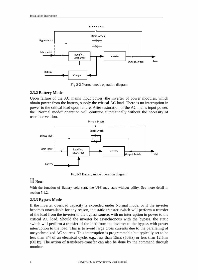
2.3.3 Bypass Mode If the inverter overload capacity is exceeded under Normal mode, or if the inverter becomes unavailable for any reason, the static transfer switch will perform a transfer of the load from the inverter to the bypass source, with no interruption in power to the critical AC load. Should the inverter be asynchronous with the bypass, the static switch will perform a transfer of the load from the inverter to the bypass with power interruption to the load. This is to avoid large cross currents due to the paralleling of unsynchronized AC sources. This interruption is programmable but typically set to be less than 3/4 of an electrical cycle, e.g., less than 15ms (50Hz) or less than 12.5ms (60Hz). The action of transfer/re-transfer can also be done by the command through monitor.
Tower UPS 10kVA~40kVA User Manual 7
Installation Instruction
Rectifier/Discharger
Main Input
Static Switch
Manual Bypass
Inverter
Charger
Load
Battery
Bypass Input
Output Switch
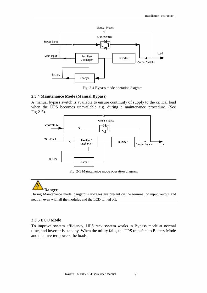
Fig. 2-4 Bypass mode operation diagram
2.3.4 Maintenance Mode (Manual Bypass) A manual bypass switch is available to ensure continuity of supply to the critical load when the UPS becomes unavailable e.g. during a maintenance procedure. (See Fig.2-5).
Fig .2-5 Maintenance mode operation diagram
Danger During Maintenance mode, dangerous voltages are present on the terminal of input, output and neutral, even with all the modules and the LCD turned off.
2.3.5 ECO Mode To improve system efficiency, UPS rack system works in Bypass mode at normal time, and inverter is standby. When the utility fails, the UPS transfers to Battery Mode and the inverter powers the loads.
Installation Instruction
8 Tower UPS 10kVA~40kVA User Manual
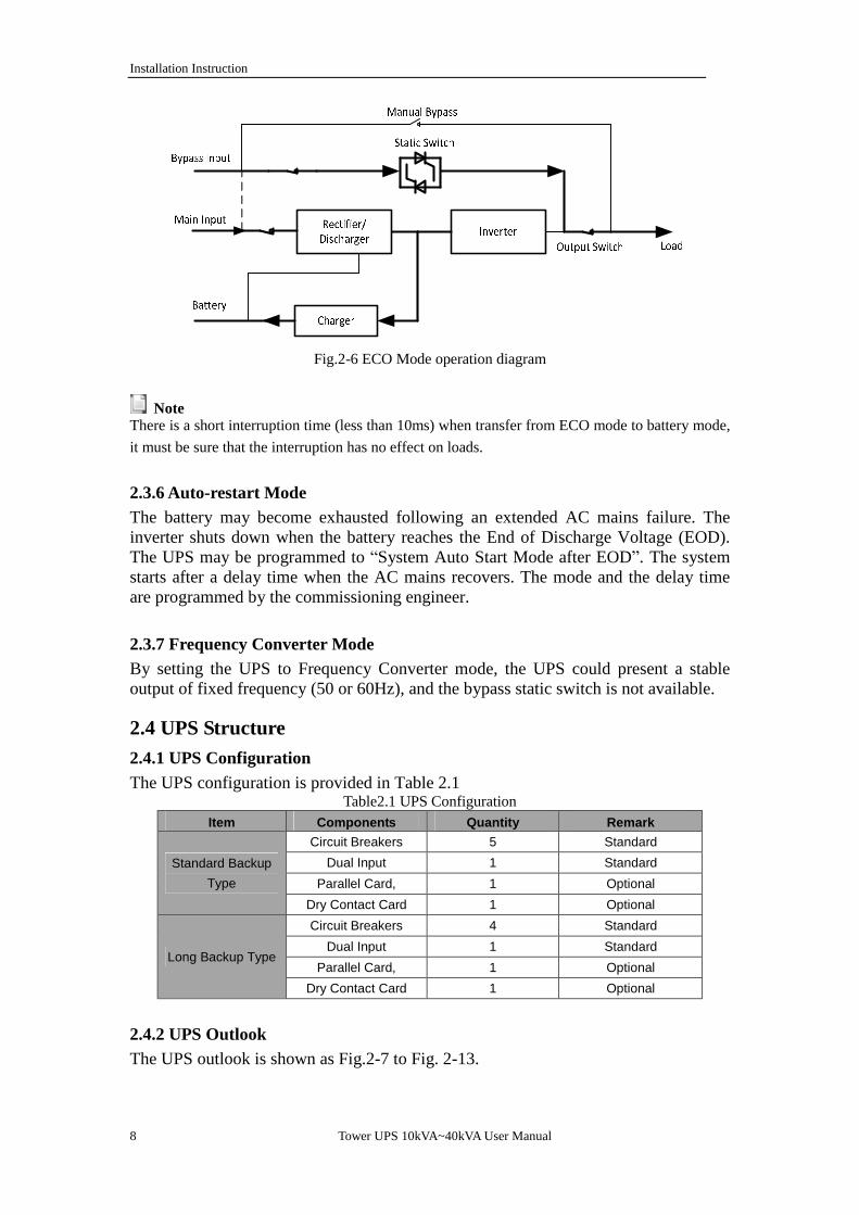
Fig.2-6 ECO Mode operation diagram
Note
There is a short interruption time (less than 10ms) when transfer from ECO mode to battery mode, it must be sure that the interruption has no effect on loads.
2.3.6 Auto-restart Mode The battery may become exhausted following an extended AC mains failure. The inverter shuts down when the battery reaches the End of Discharge Voltage (EOD). The UPS may be programmed to “System Auto Start Mode after EOD”. The system starts after a delay time when the AC mains recovers. The mode and the delay time are programmed by the commissioning engineer.
2.3.7 Frequency Converter Mode By setting the UPS to Frequency Converter mode, the UPS could present a stable output of fixed frequency (50 or 60Hz), and the bypass static switch is not available.
2.4 UPS Structure 2.4.1 UPS Configuration The UPS configuration is provided in Table 2.1
Table2.1 UPS Configuration Item Components Quantity Remark
Standard Backup Type
Circuit Breakers 5 Standard Dual Input 1 Standard
Parallel Card, 1 Optional Dry Contact Card 1 Optional
Long Backup Type
Circuit Breakers 4 Standard Dual Input 1 Standard
Parallel Card, 1 Optional Dry Contact Card 1 Optional
2.4.2 UPS Outlook The UPS outlook is shown as Fig.2-7 to Fig. 2-13.

Tower UPS 10kVA~40kVA User Manual 9
Installation Instruction
Fig.2-7 10/15kVA System outlook (Long backup type)
Fig.2-8 20/30kVA System outlook (Long backup type)

Installation Instruction
10 Tower UPS 10kVA~40kVA User Manual
Fig. 2-9 20/30kVA System outlook (Standard backup type)

Tower UPS 10kVA~40kVA User Manual 11
Installation Instruction
LEDLCD
Operational Button
Buzzer
Ventilationpanel
Fig. 2-10 10-30kVA front appearance
Protective Cover
DryContact
Parallel Board
USB
RS485
RS232
Connection terminal
Output CB
Main input CB
Bypass Input CB
Maintenance CB
Battery Cold Start
SNMP
Fig. 2-11 10/15 kVA back appearance

Installation Instruction
12 Tower UPS 10kVA~40kVA User Manual
SNMPDry Contact
Parallel board
Main input CB
Connection terminals
232
Cold startbutton
485
Bypass Input CB
Maintenance switch
Output CB
Protective cover
Air vent
USB
Fig. 2-12 20/30kVA back appearance
Parallel boardDry contact
Bypass Input CB
Input CB
Air vent
Connection terminals
Cold start
Output CB
Maintenance switch
Fig. 2-13 40kVA long type back appearance

Tower UPS 10kVA~40kVA User Manual 13
Installation Instruction
Fig.2-14 40kVA standard type front appearance
Note The Standard product is configured with single input; the dual-input option is available, with an additional breaker for the main input.

Installation Instruction
14 Tower UPS 10kVA~40kVA User Manual
3. Installation Instruction
3.1 Location As each site has its requirements, the installation instructions in this section are to act as a guide for the general procedures and practices that should be observed by the installing engineer. 3.1.1 Installation Environment The UPS is intended for indoor installation and uses forced convection cooling by internal fans. Please make sure there is enough space for the UPS ventilation and cooling. Keep the UPS far away from water,heat and inflammable and explosive, corrosive material. Avoid installing the UPS in the environment with direct sunlight, dust, volatile gases, corrosive material and high salinity. Avoid installing the UPS in the environment with conductive dirt. The operating environment temperature for battery is 20℃-25℃. Operating above 25℃ will reduce the battery life, and operation below 20℃ will reduce the battery capacity. The battery will generate a little amount of hydrogen and oxygen at the end of charging; ensure the fresh air volume of the battery installation environment must meet EN50272-2001 requirements. If external batteries are to be used, the battery circuit breakers (or fuses) must be mounted as close as possible to the batteries, and the connecting cables should be as short as possible. 3.1.2 Site Selection Ensure the ground or installation platform can bear the weight of the UPS cabinet ,batteries and battery rack. No vibration and less than 5 degree inclination horizontally. The equipment should be stored in a room so as to protect it against excessive humidity and heat sources. The battery needs to be stored in dry and cool place with good ventilation. The most suitable storage temperature is 20 ºC to 25ºC. 3.1.3 Size and Weight The size of three dimensions for the UPS cabinet is shown in Fig.3-1.
Attention Ensure there is at least 0.8m before the front of the cabinet so as to easily maintain the power module and at least 0.5m behind for ventilation and cooling. The room reserved for the cabinet is shown in Fig.3-3.
Tower UPS 10kVA~40kVA User Manual 15
Installation Instruction
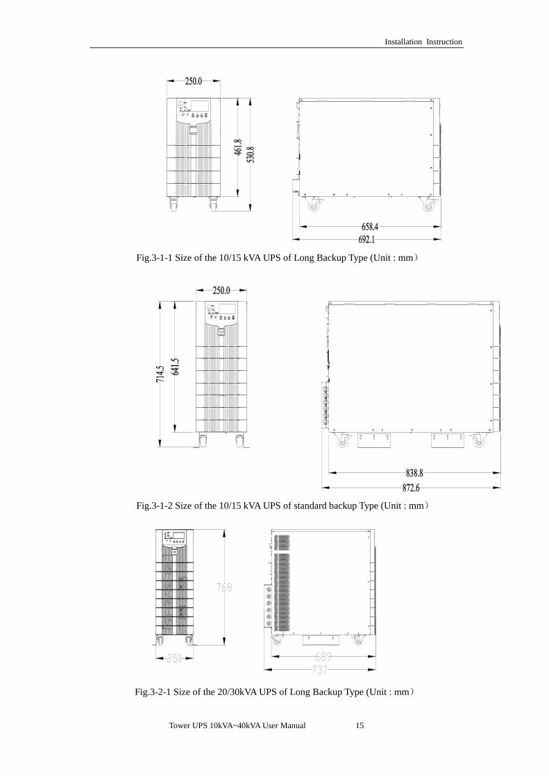
Fig.3-1-1 Size of the 10/15 kVA UPS of Long Backup Type (Unit : mm)
Fig.3-1-2 Size of the 10/15 kVA UPS of standard backup Type (Unit : mm)
Fig.3-2-1 Size of the 20/30kVA UPS of Long Backup Type (Unit : mm)

Installation Instruction
16 Tower UPS 10kVA~40kVA User Manual
Fig.3-2-2 Size of the 20/30 kVA UPS of Standard Backup Type (Unit : mm)
Fig.3-3-1 Size of the 40kVA UPS Long Backup Type (Unit : mm)(Unit : mm)

Tower UPS 10kVA~40kVA User Manual 17
Installation Instruction
Fig.3-3-2 Size of the 40kVA UPS Standard Type (Unit: mm)

Installation Instruction
18 Tower UPS 10kVA~40kVA User Manual
500
500
800
Fig.3-4 Room reserved for the cabinet(Unit:mm)
The weight for the UPS cabinet is shown in Table 1.1
Table 1.1Weight for the cabinet
Configuration Weight 10kVA/15kVA Standard Backup Type 50kg(No Batteries Included)
10kVA/15kVA Long Backup Type 28kg 20kVA/30kVA Standard Backup Type 88kg(No Batteries Included)
20kVA/30kVA Long Backup Type 50kg 40kVA Long Backup Type 61kg
40kVA standard Type 140kg
3.2 Unloading and Unpacking 3.2.1 Moving and Unpacking of the Cabinet The steps to move and unpack the cabinet are as follows: 1. Check if any damages to the packing. (If any, contact to the carrier) 2. Transport the equipment to the designated site by forklift, as shown in Fig.3-5.

Tower UPS 10kVA~40kVA User Manual 19
Installation Instruction
Fig.3-5 Transport to the designated site
3. Unpack the package (see Fig.3-6).
Fig.3-6 Disassemble the case
4. Remove the protective foam around the cabinet.

Installation Instruction
20 Tower UPS 10kVA~40kVA User Manual
Fig.3-7 Remove the protective foam
5. Check the UPS. (a) Visually examine if there are any damages to UPS during transportation. If any, contact to the carrier.
(b) Check the UPS with the list of the goods. If any items are not included in the list, contact to our company or the local office.
6. Dismantle the bolt that connects the cabinet and wooden pallet after disassembly. 7. Move the cabinet to the installation position.
Attention Be careful while removing to avoid scratching the equipment.
Attention The waste materials of unpacking should be disposed to meet the demand for environmental protection.
3.3 Positioning 3.3.1 Positioning Cabinet The UPS cabinet has two way of supporting itself: One is to support itself temporarily by the four wheels at the bottom,making it convenient to adjust the position of the cabinet;The other is by anchor bolts to support the cabinet permanently after adjusting the position of the cabinet. The supporting structure is shown in Fig. 3-8.

Tower UPS 10kVA~40kVA User Manual 21
Installation Instruction
nchor bolt
Wheels
Bracket
Fig.3-8 Supporting structure(Bottom view)
The steps to position the cabinet are as follows: 1. Ensure the supporting structure is in good condition and the mounting floor is
smooth and strong. 2. Retract the anchor bolts by turning them counterclockwise using wrench, the
cabinet is then supported by the four wheels. 3. Adjust the cabinet to the right position by the supporting wheels. 4. Put down the anchor bolts by turning them clockwise using wrench, the cabinet is
then supported by the four anchor bolts. 5. Ensure the four anchor bolts are in the same height and the cabinet is fixed and
immovable. 6. Positioning done.
Attention Auxiliary equipment is needed when the mounting floor is not solid enough to support the cabinet, which helps distribute the weight over a larger area. For instance, cover the floor with iron plate or increase the supporting area of the anchor bolts.
3.4 Battery Three terminals(positive,neutral,negative )are drawn from the battery unit and connected to UPS system. The neutral line is drawn from the middle of the batteries in series (See Fig.3-9).

Installation Instruction
22 Tower UPS 10kVA~40kVA User Manual
Fig 3-9 Battery string wiring diagram
Danger The battery terminal voltage is of more than 200Vdc, please follow the safety instructions to avoid electric shock hazard. Ensure the positive, negative, neutral electrode is correctly connected from the battery unit terminals to the breaker and from the breaker to the UPS system.
3.5 Cable Entry Cables can enter the UPS cabinet from the side or from the bottom. Cable entry is made possible through a blanking plate fitted at the bottom of the equipment. The cable entry is shown in Fig.3-11.
Cable connection
Cable connection Fig.3-10 Cable entry

Tower UPS 10kVA~40kVA User Manual 23
Installation Instruction
3.6 Power Cables
3.6.1 Specifications The UPS power cables are recommended in Table 3.2.
Table 3.2 Recommended cables for power cables
Contents 10/15kVA 20/30kVA 40kVA
Main Input
Main Input Current(A) 18/28A 35/55A 70A
Cable Section (mm²)
A 6 10 16
B 6 10 16
C 6 10 16
N 6 10 16
Main Output
Main Output Current(A) 15/23A 30/45A 60A
Cable Section (mm²)
A 6 10 16
B 6 10 16
C 6 10 16
N 6 10 16
Bypass Input (Optional)
Bypass Input Current(A) 15/23A 30/45A 60A
Cable Section (mm²)
A 6 10 16
B 6 10 16
C 6 10 16
N 6 10 16
Battery Input
Battery Input current(A) 20/30A 40/60A 80A
Cable Section (mm²)
+ 8 16 25
- 8 16 25
N 8 16 25
PE Cable Section (mm²)
PE 6 10 16
Note
The recommended cable section for power cables are only for situations described below: l Ambient temperature:30℃. l AC loss less than 3%,DC loss less than 1%,The length of the AC power cables are no longer
than 50 m and the length of the DC power cables are no longer than 30 m. l Currents listed in the table are based on the 208V system (Line-to-line voltage). l The size of neutral lines should be 1.5~1.7 times the value listed above when the predominant
load is non-linear.
3.6.2 Specifications for Power Cables Terminal Specifications for power cables connector are listed as Table 3.3.
Table 3.3 Requirements for power module terminal
Port Connection Bolt Bolt Aperture Torque Moment
Mains input Cables crimped OT terminal M6 7mm 4.9Nm

Installation Instruction
24 Tower UPS 10kVA~40kVA User Manual
Bypass Input Cables crimped OT terminal
M6 7mm 4.9Nm
Battery Input Cables crimped OT terminal
M6 7mm 4.9Nm
Output Cables crimped OT terminal
M6 7mm 4.9Nm
PE Cables crimped OT terminal
M6 7mm 4.9Nm
3.6.3 Circuit Breaker The circuit breakers (CB) for the system are recommended in Table 3.4.
Table 3.4 Recommended CB Installed position 10/15kVA 20kVA 30kVA 40kVA
Battery CB 32A,250Vdc 50A,250Vdc 63A,250Vdc 100A,250Vdc
Attention The CB with RCD (Residual Current Device) is not suggested for the system.
3.6.4 Connecting Power Cables The steps of connecting power cables are as follows: 1. Verify that all the switches of the UPS are completely open and the UPS internal
maintenance bypass switch is open. Attach necessary warning signs to these switches to prevent unauthorized operation.
2. Open the back door of the cabinet, remove the plastic cover. The input and output terminal, battery terminal and protective earth terminal are shown in Fig.3-11 &Fig 3.13.
Fig.3-11 connections terminals for 10/15kVA
Fig.3-12 connections terminals for 20/30kVA

Tower UPS 10kVA~40kVA User Manual 25
Installation Instruction
Fig.3-13 connections terminals for 40kVA
3. Connect the protective earth wire to protective earth terminal (PE). 4. Connect the AC input supply cables to the Input terminal and AC output supply
cables to the Output terminal. 5. Connect the Battery cables to the Battery terminal. 6. Check to make sure there is no mistake and re-install all the protective covers. Note: mA, mB, mC standard for Main input phase A,B and C; bA, bB, bC standard for Bypass Input phase A,B and C.
Attention The operations described in this section must be performed by authorized electricians or qualified technical personnel. If you have any difficulties, contact the manufacturer or agency.
Warning l Tighten the connections terminals to enough torque moment, refer to Table 3.3, and please
ensure correct phase rotation. l The grounding cable and neutral cable must be connected in accordance with local and national
codes. l When the cable holes does not goes through by cables, it should be filled by the hole stopper
3.7 Control and Communication Cables The front panel of the bypass module provides dry contact interface (J2-J11) and communication interface (RS232,RS485,SNMP ,Intelligent card interface and USB port),as it is shown in Fig.3-13.

Installation Instruction
26 Tower UPS 10kVA~40kVA User Manual
Intelligent card slot
Cold start
232 USBParallel board
Dry Contact485
Fig.3-13 Dry contact &communication interface
3.7.1 Dry Contact Interface Dry contact interface includes port J2-J11 and the functions of the dry contact are shown in Table 3.5.
Table 3.5 Functions of the port Port Name Function
J2-1 TEMP_BAT Detection of battery temperature J2-2 TEMP_COM Common terminal for temperature detection J3-1 ENV_TEMP Detection of environmental temperature J3-2 TEMP_COM Common terminal for temperature detection J4-1 REMOTE_EPO_NC Trigger EPO when disconnect with J4-2 J4-2 +24V_DRY +24V J4-3 +24V_DRY +24V J4-4 REMOTE_EPO_NO Trigger EPO when shorted with J4-3 J5-1 +24V_DRY +24V
J5-2 GEN_CONNECTED Input dry contact , function is settable , Default: interface for generator
J5-3 GND_DRY Ground for +24V
J6-1 BCB Drive Output dry contact, function is settable. Default: Battery trip signal
J6-2 BCB_Status Input dry contact, function is settable. Default: BCB Status and BCB Online, (Alert no battery when BCB Status is invalid).
J7-1 GND_DRY Ground for +24V
J7-2 BCB_Online Input dry contact, function is settable. Default: BCB Status and BCB Online (Alert no battery when BCB Status is invalid).
J8-1 BAT_LOW_ALARM_NC Output dry contact (Normally closed), function is settable. Default: Low battery alarming
J8-2 BAT_LOW_ALARM_NO Output dry contact (Normally open), function is settable.
Tower UPS 10kVA~40kVA User Manual 27
Installation Instruction
Default: Low battery alarming J8-3 BAT_LOW_ALARM_GND Common terminal for J8-1 and J8-2
J9-1 GENERAL_ALARM_NC Output dry contact, (Normally closed) function is settable. Default: Fault alarming
J9-2 GENERAL_ALARM_NO Output dry contact, (Normally open) function is settable. Default: Fault alarming
J9-3 GENERAL_ALARM_GND Common terminal for J9-1 and J9-2
J10-1 UTILITY_FAIL_NC Output dry contact, (Normally closed) function is settable. Default: Utility abnormal alarming
J10-2 UTILITY_FAIL_NO Output dry contact, (Normally open) function is settable. Default: Utility abnormal alarming
J10-3 UTILITY_FAIL_GND Common terminal for J10-1 and J10-2
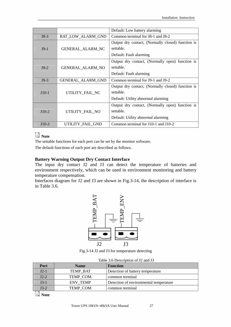
Note The settable functions for each port can be set by the monitor software. The default functions of each port are described as follows. Battery Warning Output Dry Contact Interface The input dry contact J2 and J3 can detect the temperature of batteries and environment respectively, which can be used in environment monitoring and battery temperature compensation. Interfaces diagram for J2 and J3 are shown in Fig.3-14, the description of interface is in Table 3.6.
J2 J3
TEM
P_B
AT
TEM
P_EN
V
Fig.3-14 J2 and J3 for temperature detecting
Table 3.6 Description of J2 and J3
Port Name Function J2-1 TEMP_BAT Detection of battery temperature J2-2 TEMP_COM common terminal J3-1 ENV_TEMP Detection of environmental temperature J3-2 TEMP_COM common terminal
Note

Installation Instruction
28 Tower UPS 10kVA~40kVA User Manual
Specified temperature sensor is required for temperature detection (R25=5Kohm, B25/50=3275), please confirm with the manufacturer, or contact the local maintenance engineers when placing an order. Remote EPO Input Port J4 is the input port for remote EPO. It requires shorting NC and +24V and disconnecting NO and +24V during normal operation, and the EPO is triggered when opening NC and +24V or shorting the NO and +24V. The port diagram is shown in Fig.3-15, and port description is shown in Table 3.7.
EPO
_NC
+24V
+24V
Fig.3-15 Diagram of input port for remote EPO
Table 3.7 Description of input port for remote EPO Port Name Function J4-1 REMOTE_EPO_NC Trigger EPO when disconnect with J4-2 J4-2 +24V_DRY +24V J4-3 +24V_DRY +24V
J4-4 REMOTE_EPO_NO Trigger EPO when connect with J4-3
Generator Input Dry Contact The default function of J5 is the interface for generator J5 Connect pin 2 of J5 with +24V power supply; it indicates that the generator has been connected with the system. The interface diagram is shown in Fig.3-16, and interface description is shown in Table 3.8.
J5
GEN
+24V
AUX-N.O.
AUX-N.O.
Generator
Fig. 3-16 Diagram of status interface and connection of generator

Tower UPS 10kVA~40kVA User Manual 29
Installation Instruction
Table 3.8 Description of status interface and connection of generator Port Name Function J5-1 +24V_DRY +24V J5-2 GEN_CONNECTED Connection status of generator J5-3 GND_DRY Power ground for +24V
BCB Input Port The default function of J6 and J7 are the ports of BCB. The port diagram is shown in Fig.3-17, and description is shown in Table 3.9.
BCB
_DRV
BCB
_CO
NT
BCB
_ON
L
Fig.3-17 BCB Port
Table 3.9 Description of BCB port Port Name Function
J6-1 BCB_DRIV BCB contact drive, provides +24V voltage,20mA drive signal
J6-2 BCB_Status BCB contact status, connect with the normally open signal of BCB
J7-1 GND_DRY Power ground for +24V
J7-2 BCB_Online BCB on-line input (normally open) , BCB is on-line when the signal is connecting with J7-1
Battery Warning Output Dry Contact Interface
The default function of J8 is the output dry contact interface, which presents the battery warnings of low or excessive voltage, when the battery voltage is lower than set value, an auxiliary dry contact signal will be activated via the isolation of a relay. The interface diagram is shown in Fig.3-17, and description is shown in Table 3.10.

Installation Instruction
30 Tower UPS 10kVA~40kVA User Manual
Fig.3-18 Battery warning dry contact interface diagram
Table3.10 Battery warning dry contact interface description Port Name Function
J8-1 BAT_LOW_ALARM_NC Battery warning relay (normally closed) will be open during warning
J8-2 BAT_LOW_ALARM_NO Battery warning relay (normally open) will be closed during warning
J8-3 BAT_LOW_ALARM_GND Common terminal
General Alarm Output Dry Contact Interface The default function of J9 is the general alarm output dry contact interface. When one or more warnings are triggered, an auxiliary dry contact signal will be active via the isolation of a relay. The interface diagram is shown in Fig.3-19, and description is shown in Table 3.11.
Fig.3-19 Integrated warning dry contact interface diagram Table3.11 General alarm dry contact interface description
Port Name Function
J9-1 GENERAL_ALARM_NC Integrated warning relay (normally closed) will be open during warning
J9-2 GENERAL_ALARM_NO Integrated warning relay (normally open) will be closed during warning
J9-3 GENERAL_ALARM_GND Common terminal
Utility Fail Warning Output Dry Contact Interface The default function of J10 is the output dry contact interface for utility failure warning, when the utility fails, the system will send a utility failure warning information, and provide an auxiliary dry contact signal via the isolation of a relay. The interface diagram is shown in Fig.3-20, and description is shown in Table 3.12.

Tower UPS 10kVA~40kVA User Manual 31
Installation Instruction
Fig.3-20 utility failure warning dry contact interface diagram
Table 3.12 Utility failure warning dry contact interface description
Port Name Function
J10-1 UTILITY_FAIL_NC Mains failure warning relay(normally closed) will be open during warning
J10-2 UTILITY_FAIL_NO Mains failure warning relay (normally open) will be closed during warning
J10-3 UTILITY_FAIL_GND Common terminal
3.7.2 Communication Interface RS232、RS485 and USB port: Provide serial data which can be used for commissioning and maintenance by authorized engineers or can be used for networking or integrated monitoring system in the service room. SNMP: Used on site installation for communication (Optional). Intelligent card interface:Extension dry contact interface (Optional).

Operations
32 Tower UPS 10kVA~40kVA User Manual
4. LCD Panel
4.1 Introduction This chapter introduces the functions and operator instructions of the operator control and display panel in detail, and provides LCD display information, including LCD display types, detailed menu information, prompt window information and UPS alarm information.
4.2 LCD panel for Cabinet The structure of operator control and display panel for cabinet is shown in Fig.4-1.
Fig.4-1 Control and display panel for cabinet
The LCD panel for cabinet is divided into three functional areas:LED indicator,control and operation keys and LCD screen.
4.2.1 LED Indicator There are 6 LEDs on the panel to indicate the operating status and fault. (See Fig.4-1).The description of indicators is shown in Table 4.1
Table 4.1 Status description of indicators
Indicators State Description
Rectifier indicator
Steady green Rectifier normal for all modules Flashing
green Rectifier normal for at least one module, mains normal
Steady red Rectifier fault Flashing red Mains abnormal for at least one module
Off Rectifier not operating
Battery indicator
Steady green Battery charging Flashing
green Battery discharging
Steady red Battery abnormal (battery failure, no battery or battery reversed) or battery converter abnormal (failure, over current or over temperature) , EOD
Flashing red Battery low voltage Off Battery and battery converter normal, battery not charging

Tower UPS 10kVA~40kVA User Manual 33
Operations
Indicators State Description
Bypass indicator
Steady green Load supplied by bypass
Steady red Bypass abnormal or out of normal range, or static bypass switch fault
Flashing red Bypass voltage abnormal Off Bypass normal
Inverter indicator
Steady green Load supplied by inverter Flashing
green Inverter on, start, synchronization or standby (ECO mode) for at least one module
Steady red System output not supplied by inverter, inverter fault for at least one module.
Flashing red System output supplied by inverter, inverter fault for at least one module.
Off Inverter not operating for all modules
Load indicator
Steady green UPS output ON and normal
Steady red UPS overload time is out, or output short, or output no power supply
Flashing red Overload output of UPS Off No output of UPS
Status indicator
Steady green Normal operation Steady red Failure
There are two different types of audible alarm during UPS operation, as shown in Table 4.2.
Table 4.2 Description of audible alarm Alarm Description
Two short alarm with a long one
when system has general alarm (for example: AC fault),
Continuous alarm When system has serious faults (for example: fuse or hardware fault)
4.2.2 Control and Operation Keys Control and operation keys include four keys, which are used together with LCD screen. The functions description is shown in Table 4.3.
Table 4.3 Functions of Control and operation keys
Function Key Description
EPO Long press,cut off the load power (shut down the rectifier, inverter, static bypass and battery)
TAB Transfer ENTER Confirm
ESC Quit
Attention When bypass frequency is over track, there is interruption time(less than 10ms) for transferring from bypass to inverter.

Operations
34 Tower UPS 10kVA~40kVA User Manual
4.2.3 LCD Screen After the monitoring system starts self-test, the system enters the home page, following the welcome window. The home page is shown in Fig.4-2. Home page consists of System Information Window, Menu Window and Current Command and Record Menu.
Fig.4-2 Home page
The description of LCD icons is shown in Table 4.4. Table 4.4 Description of LCD Icons
Icon Description
Power On/Off button
Parameters of Main & Bypass Input
History log
Function set(Fault Clear, Battery Test, Battery Maintenance, language set, Manual Transfer, etc.), System Configuration(For Service Engineer Only)
Parameters of Battery, DC bus information, Temperature etc.
Parameters of Output & Load
Warning, S-code and System Information(Rated parameters, Version Information)
Mute on/off
Page Up & Down
Select the icon, system enters the corresponding page; take the icon (Main Input) for example, as shown in Fig.4-3.

Tower UPS 10kVA~40kVA User Manual 35
Operations
BA CI/P MAIN
220.1 V45.0 A50.01 Hz 0.99 PF
HOME NEXT
220.1 V45.0 A50.01 Hz 0.99 PF
220.1 V45.0 A50.01 Hz 0.99 PF
Fig.4-3 Main input page
Select the icon of ; it will display the information of battery, as shown in Fig.4-4.
BATTERY P.1
Batt BoostDischag Times 10
40
NEXTHOME
Batt Number
Status
Batt Volt5.0 ABatt Curr
240.0 V240.0 V5.0 A
Fig 4-4 Battery Information
Select ,to view the current status of the UPS ;
Select ,to turn off the buzzer raising from general alarms; Select ,to view the system information and maintenance code;
Note
The LCD will go to sleep in 2 minutes during which time if there are no warnings or faults. Press any button to wake the screen up

Operations
36 Tower UPS 10kVA~40kVA User Manual
4.3 System Information Window System Information Window displays the current time and UPS model, as is shown in the following Table 4.5.
Table 4.5 Description of System Information Window
Content Description
3320S UPS mode:3-phase in 3-phase out 20kVA,standard backup type
16:30 Current time
4.4 Menu Window The Menu Window displays the menu name of data window, while the data window displays the related contents of selected menu in menu window. Select UPS menu and data window to browse related parameters of UPS and set related functions. The details are given in Table 4.6.
Table.4.6 Description of UPS Menu Menu name Menu item Meaning
Main input
V phase(V) Voltage I phase(A) Current Freq.(Hz) Frequency PF Power factor
Bypass input
V phase(V) Voltage Freq. (Hz) Frequency I phase(A) Current PF Power factor
Output
V phase(V) Voltage I phase(A) Current Freq. (Hz) Frequency PF Power factor
This UPS module’s load
Sout (kVA) Apparent Power Pout (kW) Active Power Qout (kVAR) Reactive Power Load (%) Load percent
Battery data
Environmental Temp Environmental Temp Battery voltage(V) Positive and negative battery voltage Battery current A) Positive and negative battery current Battery Temp( ) ℃ Battery Temperature Remaining Time (Min.)
Remained battery backup time
Battery capacity (%) Remained battery capacity battery boost charging
Battery is working in boost charging mode
battery float charging Battery is working in float charging mode Battery disconnected Battery is not connected

Tower UPS 10kVA~40kVA User Manual 37
Operations
Menu name Menu item Meaning Current alarm
Display all current alarm. The alarms are displayed on LCD
History log Display all history logs.
Function Settings
Display calibration Adjust the accuracy of LCD display
Date format set MONTH-DATE-YEAR and YEAR-MONTH-DATE formats can be selected
Date & Time Date/Time set Language set User can set the language Communication set / Control password 1 set
User can modify control password 1
Command
Battery maintenance test
This test will lead to the battery being partly discharged to activate battery until battery voltage is low. Bypass must be in normal condition, the battery capacity should be above 25%.
Battery self-check test
UPS transfer to battery discharge mode to test if the battery is normal. Bypass must be in normal condition, the battery capacity should be above 25%.
Stop testing Manually Stop the test including maintenance test, capacity test
UPS system information
Monitoring software version
Monitoring software version
Rectified software version
Rectifier software version
Inverted software version
Inverter software version
Serial No. The serial NO set when delivered from the factory Rated information System rated information Module model Module model
4.5 Event List The following Table4.7 gives events of UPS History Log
Table 4.7 List of History Log String
Sequence LCD Display Explanation
1 Load On UPS-Set Load On UPS 2 Load On Bypass-Set Load On Bypass 3 No Load-Set No Load (Output Power Lost) 4 Battery Boost-Set Charger is Boosting Battery Voltage
5 Battery Float-Set Charger is Floating Battery Voltage
6 Battery Discharge-Set Battery is Discharging 7 Battery Connected-Set Battery cables Connected

Operations
38 Tower UPS 10kVA~40kVA User Manual
8 Battery Not Connected-Set Battery cables Disconnected.
9 Maintenance CB Closed-Set
Maintenance CB is Closed
10 Maintenance CB Open-Set Maintenance CB is Open 11 EPO-Set Emergency Power Off
12 Module On Less-Set Valid Inverter capacity is less than the load capacity
13 Module On Less-Clear Incident above disappears 14 Generator Input-Set Generator as the Ac Input Source 15 Generator Input-Clear Incident above disappears 16 Utility Abnormal-Set Utility (Grid) Abnormal 17 Utility Abnormal-Clear Incident above disappears
18 Bypass Sequence Error-Set
Bypass voltage Sequence is reverse
19 Bypass Sequence Error-Clear
Incident above disappears
20 Bypass Volt Abnormal-Set Bypass Voltage Abnormal
21 Bypass Volt Abnormal-Clear
Incident above disappears
22 Bypass Module Fail-Set Bypass Module Fail 23 Bypass Module Fail-Clear Incident above disappears 24 Bypass Overload-Set Bypass Over load 25 Bypass Overload-Clear Incident above disappears 26 Bypass Overload Tout-Set Bypass Over Load Timeout 27 Byp Overload Tout-Clear Incident above disappears 28 Byp Freq Over Track-Set Bypass Frequency Over Track Range
29 Byp Freq Over Track-Clear
Incident above disappears
30 Exceed Tx Times Lmt-Set Transfer times (from inverter to bypass) in 1 hour exceed the limit.
31 Exceed Tx Times Lmt-Clear
Incident above disappears
32 Output Short Circuit-Set Output shorted Circuit 33 Output Short Circuit-Clear Incident above disappears 34 Battery EOD-Set Battery End Of Discharge 35 Battery EOD-Clear Incident above disappears 36 Battery Test-Set Battery Test Starts 37 Battery Test OK-Set Battery Test OK 38 Battery Test Fail-Set Battery Test fails 39 Battery Maintenance-Set Battery Maintenance Starts 40 Batt Maintenance OK-Set Battery maintenance succeeds 41 Batt Maintenance Fail-Set Battery maintenance fails
42 Module Inserted-Set N# Power Module joins the system
43 Module Exit-Set N# Power Module quits the system.

Tower UPS 10kVA~40kVA User Manual 39
Operations
44 Rectifier Fail-Set N# Power Module Rectifier Fails 45 Rectifier Fail-Clear Incident above disappears 46 Inverter Fail-Set N# Power Module Inverter Fail 47 Inverter Fail-Clear Incident above disappears 48 Rectifier Over Temp.-Set N# Power Module Rectifier Over Temperature
49 Rectifier Over Temp.-Clear
Incident above disappears
50 Fan Fail-Set N# Power Module Fan Fail 51 Fan Fail-Clear Incident above disappears 52 Output Overload-Set N# Power Module Output Over Load 53 Output Overload-Clear Incident above disappears
54 Inverter Overload Tout-Set
N# Power Module Inverter Over Load Timeout
55 INV Overload Tout-Clear Incident above disappears
56 Inverter Over Temp.-Set N# Power Module Inverter Over Temperature 57 Inverter Over Temp.-Clear Incident above disappears
58 On UPS Inhibited-Set Inhibit system transfer from bypass to UPS (inverter)
59 On UPS Inhibited-Clear Incident above disappears 60 Manual Transfer Byp-Set Transfer to bypass manually 61 Manual Transfer Byp-Set Cancel to bypass manually 62 Esc Manual Bypass-Set Escape transfer to bypass manually command 63 Battery Volt Low-Set Battery Voltage Low 64 Battery Volt Low-Clear Incident above disappears 65 Battery Reverse-Set Battery pole (positive and negative are reverse) 66 Battery Reverse-Clear Incident above disappears
67 Inverter Protect-Set N# Power Module Inverter Protect ( Inverter Voltage Abnormal or Power Back feed to DC Bus)
68 Inverter Protect-Clear Incident above disappears
69 Input Neutral Lost-Set Input Grid Neutral Lost 70 Bypass Fan Fail-Set Bypass Module Fan Fail 71 Bypass Fan Fail-Clear Incident above disappears 72 Manual Shutdown-Set N# Power Module Manually Shutdown 73 Manual Boost Charge-Set Manually Battery Boost Charge 74 Manual Float Charge-Set Manually Battery Float Charge 75 UPS Locked-Set Inhibit to shut down the UPS
76 Parallel Cable Error-Set Parallel cable in error
77 Parallel Cable Error-Clear Incident above disappears
78 Lost N+X Redundant Lost N+X Redundant
79 N+X Redundant Lost-Clear
Incident above disappears

Operations
40 Tower UPS 10kVA~40kVA User Manual
80 EOD Sys Inhibited System is inhibited to supply after the battery is EOD (end of discharging)
81 Power Share Fail-Set Power share is not in balance 82 Power Share Fail-Clear Incident above disappears 83 Input Volt Detect Fail-Set Input Voltage is abnormal
84 Input Volt Detect Fail-Clear
Incident above disappears
85 Battery Volt Detect Fail-Set
Battery Voltage is abnormal
86 Batt Volt Detect Fail-Clear Incident above disappears 87 Output Volt Fail-Set Output Voltage is abnormal 88 Output Volt Fail-Clear Incident above disappears 89 Outlet Temp. Error-Set Outlet Temperature is abnormal 90 Outlet Temp. Error-Clear Incident above disappears 91 Input Curr Unbalance-Set Input current is not balance
92 Input Curr Unbalance-Clear
Incident above disappears
93 DC Bus Over Volt-Set DC bus over Voltage 94 DC Bus Over Volt-Clear Incident above disappears 95 REC Soft Start Fail-Set Rectifier soft start fails 96 REC Soft Start Fail-Clear Incident above disappears 97 Relay Connect Fail-Set Relay in open circuit 98 Relay Connect Fail-Clear Incident above disappears 99 Relay Short Circuit-Set Relay shorted 100 Relay Short Circuit-Clear Incident above disappears
101 No Inlet Temp. Sensor-Set The inlet temperature sensor is not connected or abnormal
102 No Inlet Temp Sensor-Clear
Incident above disappears
103 No Outlet Temp. Sensor-Set
The Outlet temperature sensor is not connected or abnormal
104 No Outlet TmpSensor-Clear
Incident above disappears
105 Inlet Over Temp.-Set Inlet over temperature 106 Inlet Over Temp.-Clear Incident above disappears

Tower UPS 10kVA~40kVA User Manual 41
Operations
5. Operations 5.1 UPS Start-up 5.1.1 Start from Normal Mode The UPS must be started up by commissioning engineer after the completeness of installation. The steps below must be followed: 1. Ensure all the circuit breakers are open. 2. Close the output circuit breaker (CB) and then the input CB and the system starts
initializing. If the system has dual inputs, close both of the breakers. 3. The LCD in front of the cabinet is lit up. The system enters the home page, as
shown in Fig.4-2. 4. Notice the energy bar in the home page, and pay attention to the LED indicators.
The rectifier flashes indicating the rectifier is starting up. The LED indicators are listed below in Table 5.1.
Table 5.1 Rectifier starting up Indicator Status Indicator Status Rectifier green flashing Inverter off Battery red Load off Bypass off Status red
5. After 30S, the rectifier indicator goes steady green, presenting the finishing of
rectification and bypass static switch closes then the inverter is starting up. The LED indicators are listed below in Table.5.2.
Table 5.2 Inverter starting up Indicator Status Indicator Status Rectifier green Inverter green flashing Battery red Load green Bypass green Status red
6. The UPS transfers from the bypass to inverter after the inverter goes normal. The
LED indicators are listed below in Table 5.3. Table 5.3 Supplying the load
Indicator Status Indicator Status Rectifier green Inverter green Battery red Load green Bypass off Status red
7. The UPS is in Normal Mode. Close the battery circuit breakers and the UPS starts
charging the battery. The LED indicators are listed below in Table 5.4. Table 5.4 Normal mode
Indicator Status Indicator Status Rectifier green Inverter green Battery green Load green Bypass off Status green
8. The starting up done.

Operations
42 Tower UPS 10kVA~40kVA User Manual
Note l When the system starts, the stored setting will be loaded. l Users can browse all incidents during the process of the starting up by checking the menu Log.
5.1.2 Start from Battery The start for battery model is referring to battery cold start. The steps for the start-up are as follows: 1. Confirm the battery is correctly connected; close the external battery circuit
breakers. 2. Press the red button for the battery cold start(See Fig.5-1).The system is than
powered by the battery.
Fig.5-1 the position of the battery cold start button
3. After that, the system is starting up following steps 3 in section 5.1.1 and the system transfers to battery mode in 30S.
4. Close the external output power supply isolation to supply the load, and the system is working on battery model.
5.2 Procedure for Switching between Operation Modes 5.2.1 Switching the UPS into Battery Mode from Normal Mode The UPS transfers to Battery model immediately after input circuit breaker disconnects from the utility. 5.2.2 Switching the UPS into Bypass Mode from Normal Mode
Follow the path by selecting the icon of and then select to transfer the system to Bypass Mode.
Warning Ensure the bypass is working normally before transferring to bypass mode. Or it may cause failure.

Tower UPS 10kVA~40kVA User Manual 43
Operations
5.2.3 Switching the UPS into Normal Mode from Bypass Mode
Follow the path by selecting the icon of and then s , the system transfer to Normal Mode
Note Normally, the system will transfer to the Normal mode automatically. This function is used when the frequency of the bypass is over track and when the system needs to transfer to Normal mode by manual.
5.2.4 Switching the UPS into Maintenance Bypass Mode from Normal Mode These following procedures can transfer the load from the UPS inverter output to the maintenance bypass supply, which is used for maintaining the bypass module. 1. Transfer the UPS into Bypass mode following section 5.2.2. 2. Open the battery breaker and close the maintenance bypass breaker. And the load
is powered through maintenance bypass and static bypass. 3. The load is powered through maintenance bypass.
Protective cover Maintenance switch
Maintenance switch
Screw for protective cover
Fig.5-2 the cover of maintenance bypass breaker
Waring Once the cover on the maintenance bypass breaker is removed, the system will transfer to bypass mode automatically.
Waring Before making this operation, confirm the messages on LCD display to be sure that bypass supply is regular and the inverter is synchronous with it, so as not to risk a short interruption in powering the load.
Danger Even with the LCD turned off, the terminals of input and output may be still energized . If you need to maintain the power module, wait for 10 minutes to let the DC bus capacitor fully discharge before removing the cover.
Operations
44 Tower UPS 10kVA~40kVA User Manual
5.2.5 Switching the UPS into Normal Mode from Maintenance Bypass Mode These following procedures can transfer the load from the Maintenance Bypass mode to inverter output. 1. After finish of maintenance, close the bypass breaker and the bypass static switch
will be turned on in 30S after the LED screen goes on, the bypass indicator goes green and the load is powered through maintenance bypass and static bypass.
2. Turn off the maintenance bypass switch and fix the protection cover, and then the load is powered through bypass. The rectifier starts followed by the inverter.
3. After 60S, the system transfers to Normal mode.
Waring The system will stay on bypass mode until the cover of maintenance bypass breaker is fix.
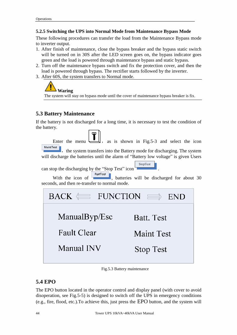
5.3 Battery Maintenance If the battery is not discharged for a long time, it is necessary to test the condition of the battery.
Enter the menu , as is shown in Fig.5-3 and select the icon
,the system transfers into the Battery mode for discharging. The system will discharge the batteries until the alarm of “Battery low voltage” is given Users
can stop the discharging by the “Stop Test” icon .
With the icon of , batteries will be discharged for about 30 seconds, and then re-transfer to normal mode.
Fig.5.3 Battery maintenance
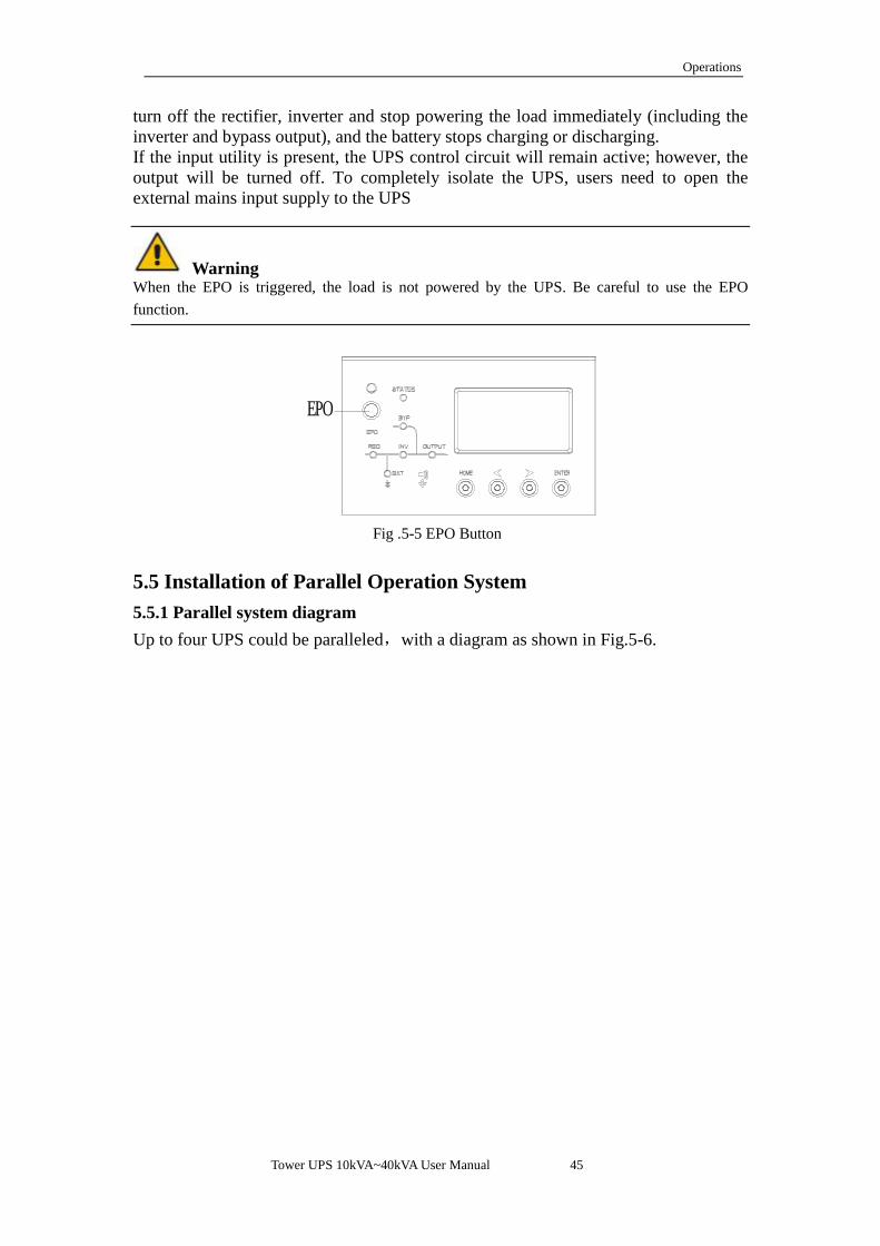
5.4 EPO The EPO button located in the operator control and display panel (with cover to avoid disoperation, see Fig.5-5) is designed to switch off the UPS in emergency conditions (e.g., fire, flood, etc.).To achieve this, just press the EPO button, and the system will
Tower UPS 10kVA~40kVA User Manual 45
Operations
turn off the rectifier, inverter and stop powering the load immediately (including the inverter and bypass output), and the battery stops charging or discharging. If the input utility is present, the UPS control circuit will remain active; however, the output will be turned off. To completely isolate the UPS, users need to open the external mains input supply to the UPS
Warning When the EPO is triggered, the load is not powered by the UPS. Be careful to use the EPO function.
EPO
Fig .5-5 EPO Button
5.5 Installation of Parallel Operation System 5.5.1 Parallel system diagram
Up to four UPS could be paralleled,with a diagram as shown in Fig.5-6.

Operations
46 Tower UPS 10kVA~40kVA User Manual
UPS1
Load Connected
Output Power Supply
Power Supply
UPS2 UPS3 UPS4
Fig. 5-6 Parallel diagram
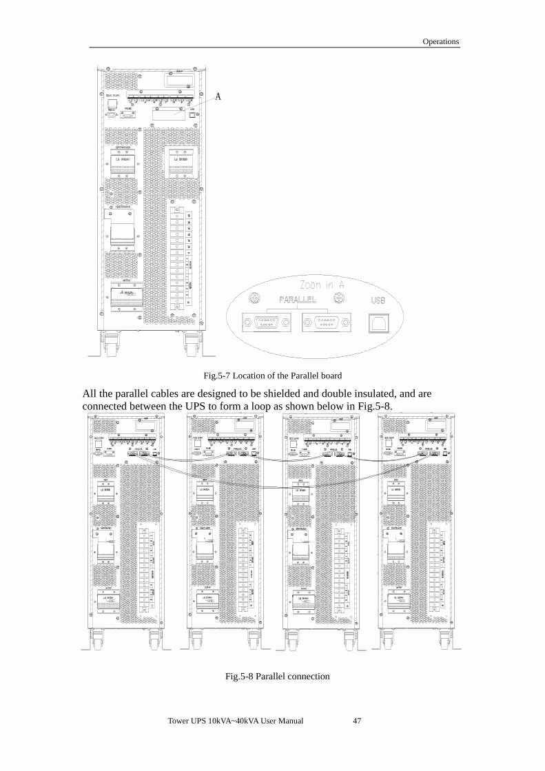
The parallel board is located at the back of the UPS cabinet, as is shown in Fig.5-7.
Tower UPS 10kVA~40kVA User Manual 47
Operations
A
Fig.5-7 Location of the Parallel board
All the parallel cables are designed to be shielded and double insulated, and are connected between the UPS to form a loop as shown below in Fig.5-8.
Fig.5-8 Parallel connection

Operations
48 Tower UPS 10kVA~40kVA User Manual
5.5.2 Parallel system setting Parallel system connection
For field installation, please connect the cables according to Fig.5-6 and Fig.5-8. In order to assure that all units are equally utilized and to comply with relevant
wiring rules, the following requirements apply: 1. All units shall be of the same rating and must be connected to the same bypass source. 2. The bypass and the main input sources must be referenced to the same neutral potential. 3. Any RCD (Residual Current detecting device), if installed, must be of an appropriate setting and located upstream of the common neutral bonding point. Alternatively, the device must monitor the protective earth currents of the system. Refer to the High Leakage Current Warning in the first part of this manual. 4. The outputs of all UPS must be connected to a common output bus.
Parallel system software setting To change the parallel system setting, please follow the steps below. 1. With the monitoring software from manufacturer, select the page of “Service
Setting” as below,
Set “System Mode” to “Parallel”, and set the “United Number” to the number of units in parallel. For the setting of system ID with a system of 3 units in parallel, for example, set the number from 0 to 2 for these 3 units accordingly. Restart the UPS when finish the setting and press the button of “Set”. Here the software setting is done. Ensure all the output parameters must be set the same.
Parallel system jumper setting There are different setting of the jumpers on the parallel board and control board
for different parallel system. The location of connectors on parallel board is shown in Fig.5-11 and control board in Fig.5-12.

Tower UPS 10kVA~40kVA User Manual 49
Operations
Fig.5-11 Connectors on Parallel board (PS1409_TF1)
INVREC
INVREC
21
2625
21 25
2619202
1
12
3334
1920 2
1
1512
16
19202
1
Zoom in jumper connnectors
Fig.5-12 Connectors on Control board (PS1203_CT1)

Operations
50 Tower UPS 10kVA~40kVA User Manual
1. Parallel boards settings A. For single UPS, no need parallel board. When a parallel board is installed, connectors of J33 to J42 should be shorted by the jumpers. B. For 2 UPS in parallel, short the connectors of J33/J35/J37/J39/J41 by jumpers on each board, keep connectors of J34/J36/J38/J39/J42 open C. For 3 or 4 UPS in parallel, keep connectors of J33-J42 open. 2. Control boards settings The control board is named as PS1203_CT1. For single UPS, keep the J21-J25 shorted by jumpers For parallel, keep all the connectors J21-J25 open. As shown in Fig.5-12. Note: The connectors not mentioned keep them untouched. When all the connection and settings are finished, follow the steps below for the operation of parallel system setup.
1. Close the output and input breaker of the first unit. Wait for the startup of bypass static switch and rectifier, about 90 seconds later; the system will transfer to normal mode. Check if there is any alarm on LCD and verify the output voltage is correct or not.
2. Turn on the second unit as the same operation with the first one; the unit will join the parallel system automatically.
3. Turn on the rest units one by one, and check the information on LCD. 4. Verify the load sharing with a certain load applied.

Tower UPS 10kVA~40kVA User Manual 51
Safety Precautions
6. Maintenance This chapter introduces UPS maintenance, including the maintenance instructions of power module and monitoring bypass module and the replacement method of dust filter.
6.1 Precautions 1. Only certified engineers are authorized to maintain the UPS. 2. The components or PCBs should be disassembled from top to bottom, so as to
prevent any inclination from high gravity center of the cabinet. 3. To ensure the safety before maintaining, measure the voltage between operating
parts and the earth with multimeter to ensure the voltage is lower than hazardous voltage, i.e. DC voltage is lower than 60Vdc, and AC maximum voltage is lower than 42.4Vac.
4. Wait 10 minutes before opening the cover of the power module or the bypass after pulling out from the Cabinet.
6.2 Instruction for Maintaining UPS For the maintenance of the UPS, please refer to chapter 5.2.4 for the instruction to
transfer to maintenance bypass mode. After maintenance, re-transfer to normal mode according to chapter 5.2.5.
6.3 Instruction for Maintaining Battery string For the Lead-Acid maintenance free battery, when maintenance the battery according to requirements, battery life can be prolonged. The battery life is mainly determined by the following factors: 1. Installation. The battery should be placed in dry and cool place with good
ventilation. Avoid direct sunlight and keep away from heat source. When installing, ensure the correct connection to the batteries with same specification.
2. Temperature. The most suitable storage temperature is 20 ºC to 25ºC. The battery life will be shortened if the battery is used under high temperature or in deep discharging status. Refer to product manual for details.
3. Charging/discharging current. The best charging current for the lead-acid battery is 0.1C .The maximum current for the battery can be 0.3C.The suggested discharging current is 0.05C-3C.
4. Charging voltage. In most of the time, the battery is in standby state. When the utility is normal, the system will charge the battery in boost mode (Constant voltage with maximum limited) to full and then transfers to the state of float charge.
5. Discharge depth. Avoid deep discharging; which will greatly reduce the life time of the battery. When the UPS runs in battery mode with light load or no load for a long time, it will cause the battery to deep discharge.
6. Check periodically. Observe if any abnormality of the battery ,measure if the voltage of each battery are in balance. Discharge the battery periodically.

Product Specification
52 Tower UPS 10kVA~40kVA User Manual
Warning Daily inspection is very important! Check and confirm the battery connection is tightened regularly, and make sure there is no abnormal heat generated from the battery.
Warning If a battery has leakage or is damaged, it must be replaced, stored in a container resistant to sulfuric acid and disposed of in accordance with local regulations. The waste lead-acid battery is a kind of hazardous waste and is one of the major contaminants controlled by government. Therefore, its storage, transportation, use and disposal must comply with the national or local regulations and laws about the disposal of hazardous waste and waste batteries or other standards. According to the national laws, the waste lead-acid battery should be recycled and reused, and it is prohibited to dispose of the batteries in other ways except recycling. Throwing away the waste lead-acid batteries at will or other improper disposal methods will cause severe environment pollution, and the person who does this will bear the corresponding legal responsibilities. 6.2.4 Installation of internal battery For 10kVA to 40kVA standard UPS, internal battery and the cables within the battery string are not provided as standard; if required, please contact your local agency. For 10-15kVA UPS, 40 pieces of 7AH/9AH batteries can be installed. For 20-30kVA UPS, 40 pieces of 12AH battery can be installed. For 40kVA UPS, 80 pieces of 12Ah batteries can be installed. For 10-15kVA UPS, there are 40 batteries of to be installed, which are divided into 4 layers.Fig.6-1 shows the installation of battery of the 10-15kVA standard UPS.
1.Dismantle the covers and crossbeams 2.Install battery and fix the crossbeams

Tower UPS 10kVA~40kVA User Manual 53
Safety Precautions
3.Connect the battery cable according to the series number 4.Recover the cover
Fig.6-1 Installation of inner battery for10, 15K standard UPS
Fig.6-2 shows the installation of batteries for 20,30K standard UPS. There are 8 groups of batteries in series, with 5 cells for each group. The interconnection among groups is via cable with Anderson Socket.
1
2
3
4
5
7
8
9
10
11
12
13
14
15
16
17
18
19
20
21
22
23
24
25
26
27
28
29
30
31
32
33
34
35
36
37
38
39
40
6
L1
L4L4
L4 L4
L4
L4
L5
Fig.6-2-1 Cable interconnection of the battery string
Layer 1. The positive of the battery 1# is connected to battery breaker CB4-2, via

Product Specification
54 Tower UPS 10kVA~40kVA User Manual
the cable labeled L1, and the negative of battery 40# is connected to CB4-6, via the cable labeled L2, as shown in Fig.6-2.
L4L4
12
34
4039
3837
36
L1
5
Fig.6-2-2 Cable connection of Lay 1
Layer 2. The positive of the battery 6# is connected to the negative of battery 5#,
via the cable labeled L4, and the negative of battery 35# is connected to the positive of battery 36#, via the cable labeled L4, as shown in Fig.6-3.
L4L4
L4
L4
67
89
10
3132
3334
35
Fig.6-2-3 Cable connection of Lay 2
Layer 3. The positive of the battery 11# is connected to the negative of battery
10#, via the cable labeled L4, and the negative of battery 30# is connected to the positive of battery 31#, via the cable labeled L4, as shown in Fig.6-4.

Tower UPS 10kVA~40kVA User Manual 55
Safety Precautions
L4L4
11
3029
2827
26
1213
1415
L4
L4
Fig.6-2-4 Cable connection of Lay 3
Layer 4. The positive of the battery 16# is connected to the negative of battery 15#, via the cable labeled L4, and the negative of battery 25# is connected to the positive of battery 26#, via the cable labeled L4. The negative of 20# and the positive of 21#, which are defined as the battery neutral, are connected to CB4-4, as shown in Fig.6-5.
L4L4
1621
2223
2425
1718
1920
Fig.6-2-5 Cable connection of Lay 4
Fig.6-2 Installation of inner battery for20, 30K standard UPS
For40kVA the battery bank has four layers. Each lay has four packages with 5 batteries contained in one package.Fig6-3 shows the connection of each layer.

Product Specification
56 Tower UPS 10kVA~40kVA User Manual
L1_N
L1_+
L2_-
L2_N
L3_N
L3_+
L4_-
L4_N
Lay1
Lay2
Lay3
Lay4
Figure 6-3 battery connection of each layer
Fig 6-3 Connection between layers (Connect according to the serial number)

Tower UPS 10kVA~40kVA User Manual 57
Safety Precautions
After the connected as shown in Fig 6-3, connect the connectors as following as zoomed in figure 6-4 Terminal+: L1_+ and L3_+ Terminal N: L1_N, L2_N, L3_N, L4_N, Terminal-: L2_- and L4_-
+
N
-
Figure 6-4 Battery terminal connection
After connect the terminal, recover the cover as shown in the following figure 6-5
Fig 6-5,Recover the cover

Product Specification
58 Tower UPS 10kVA~40kVA User Manual
Warning Make sure the polarity of the battery is correct according to the diagrams above. Test and confirm the battery voltage before connectting to the main circuit.
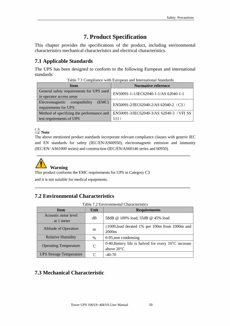
Tower UPS 10kVA~40kVA User Manual 59
Safety Precautions
7. Product Specification
This chapter provides the specifications of the product, including environmental characteristics mechanical characteristics and electrical characteristics.
7.1 Applicable Standards The UPS has been designed to conform to the following European and international standards:
Table 7.1 Compliance with European and International Standards Item Normative reference
General safety requirements for UPS used in operator access areas
EN50091-1-1/IEC62040-1-1/AS 62040-1-1
Electromagnetic compatibility (EMC) requirements for UPS
EN50091-2/IEC62040-2/AS 62040-2(C3)
Method of specifying the performance and test requirements of UPS
EN50091-3/IEC62040-3/AS 62040-3(VFI SS 111)
Note The above mentioned product standards incorporate relevant compliance clauses with generic IEC and EN standards for safety (IEC/EN/AS60950), electromagnetic emission and immunity (IEC/EN/ AS61000 series) and construction (IEC/EN/AS60146 series and 60950).
Warning
This product conforms the EMC requirements for UPS in Category C3
and it is not suitable for medical equipments.
7.2 Environmental Characteristics Table 7.2 Environmental Characteristics
Item Unit Requirements Acoustic noise level
at 1 meter dB 58dB @ 100% load, 55dB @ 45% load
Altitude of Operation m ≤1000,load derated 1% per 100m from 1000m and 2000m
Relative Humidity % 0-95,non condensing
Operating Temperature ℃ 0-40,Battery life is halved for every 10°C increase above 20°C
UPS Storage Temperature ℃ -40-70
7.3 Mechanical Characteristic

Product Specification
60 Tower UPS 10kVA~40kVA User Manual
Table 7.3 Mechanical Characteristics for Cabinet
Model Unit 10kL/15kL 10kS/15kS 20S/30S 20L/30L 40L 40S
Dimension W×D×H
mm 250*660*530 250*840*715 350*738*1335 250*680*770 250*836*770 500*840*1400
Weight kg 28 50 88 50 61 140
Color N/A BLACK,RAL 7021 Protection
Level IEC(60529)
N/A IP20
7.4 Electrical Characteristics 7.4.1 Electrical Characteristics (Input Rectifier)
Table 7.5 Rectifier AC input Mains) Item Unit Parameter
Grid System \ 3 Phases + Neutral + Ground
Rated AC Input Voltage Vac 380/400/415 (three-phase and sharing neutral with
the bypass input) Rated Frequency Vac 50/60Hz
Input voltage range Vac 304~478Vac (Line-Line),full load
228V~304Vac (Line-Line),load decrease linearly according to the min phase voltage
Input Frequency range Hz 40~70 Input Power factor PF >0.99
THDI THDI% <3% (full Linear Load)
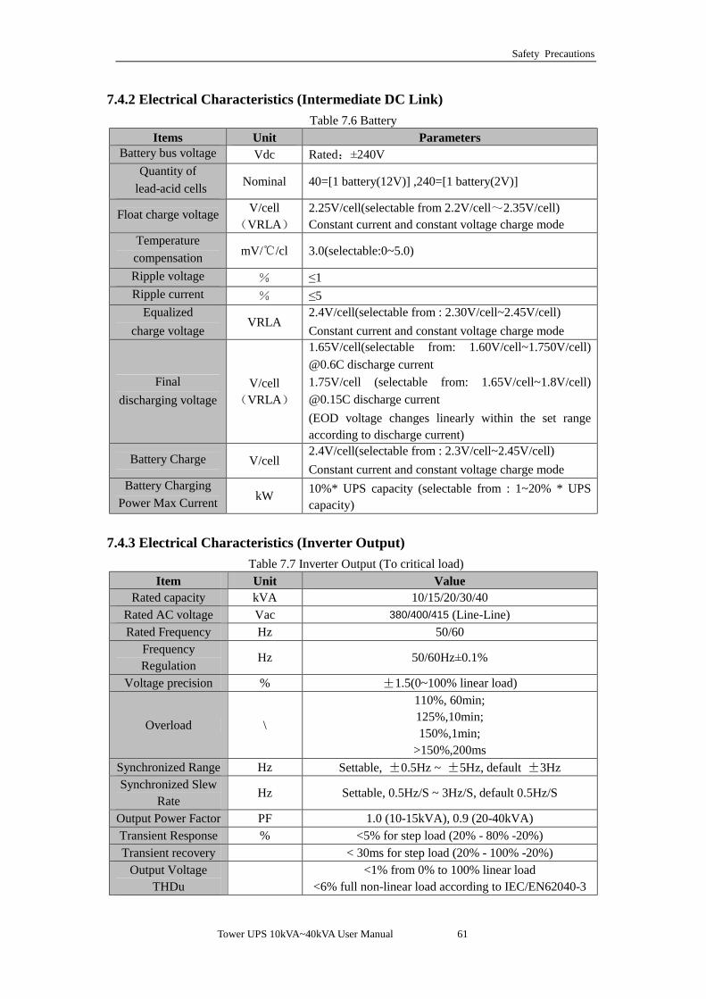
Tower UPS 10kVA~40kVA User Manual 61
Safety Precautions
7.4.2 Electrical Characteristics (Intermediate DC Link) Table 7.6 Battery
Items Unit Parameters Battery bus voltage Vdc Rated:±240V
Quantity of lead-acid cells Nominal 40=[1 battery(12V)] ,240=[1 battery(2V)]
Float charge voltage V/cell(VRLA)
2.25V/cell(selectable from 2.2V/cell~2.35V/cell) Constant current and constant voltage charge mode
Temperature compensation mV/ /cl℃ 3.0(selectable:0~5.0)
Ripple voltage % ≤1 Ripple current % ≤5
Equalized charge voltage
VRLA 2.4V/cell(selectable from : 2.30V/cell~2.45V/cell) Constant current and constant voltage charge mode
Final discharging voltage
V/cell(VRLA)
1.65V/cell(selectable from: 1.60V/cell~1.750V/cell) @0.6C discharge current 1.75V/cell (selectable from: 1.65V/cell~1.8V/cell) @0.15C discharge current (EOD voltage changes linearly within the set range according to discharge current)
Battery Charge V/cell 2.4V/cell(selectable from : 2.3V/cell~2.45V/cell) Constant current and constant voltage charge mode
Battery Charging Power Max Current kW 10%* UPS capacity (selectable from : 1~20% * UPS
capacity)
7.4.3 Electrical Characteristics (Inverter Output) Table 7.7 Inverter Output (To critical load)
Item Unit Value Rated capacity kVA 10/15/20/30/40
Rated AC voltage Vac 380/400/415 (Line-Line) Rated Frequency Hz 50/60
Frequency Regulation
Hz 50/60Hz±0.1%
Voltage precision % ±1.5(0~100% linear load)
Overload \
110%, 60min; 125%,10min; 150%,1min;
>150%,200ms Synchronized Range Hz Settable, ±0.5Hz ~ ±5Hz, default ±3Hz Synchronized Slew
Rate Hz Settable, 0.5Hz/S ~ 3Hz/S, default 0.5Hz/S
Output Power Factor PF 1.0 (10-15kVA), 0.9 (20-40kVA) Transient Response % <5% for step load (20% - 80% -20%) Transient recovery < 30ms for step load (20% - 100% -20%)
Output Voltage THDu
<1% from 0% to 100% linear load
<6% full non-linear load according to IEC/EN62040-3

Product Specification
62 Tower UPS 10kVA~40kVA User Manual
7.4.4 Electrical Characteristics (Bypass Mains Input) Table 7.8 Bypass Mains Input
Item Unit Value
Rated AC voltage Vac 380/400/415
(three-phase four-wire and sharing neutral with the bypass)
Overload %
125% Long term operation; 125%~130% for 10min; 130%~150% for 1min;
150%~400% for 1s; >400% ,less than 200ms
Current rating of neutral cable A 1.7×In
Rated frequency Hz 50/60 Switch time
(between bypass and inverter)
ms Synchronized transfer: 0ms
Bypass voltage range %
Settable, default -20%~+15% Upper limit: +10%, +15%, +20%, +25%
Lower limit: -10%, -15%, -20%, -30%, -40% Bypass
frequency range %Hz Settable, ±1Hz, ±3Hz, ±5Hz
Synchronized Range Hz Settable ±0.5Hz~±5Hz, default ±3Hz
7.5 Efficiency Table 7.9 Efficiency
Rated power(kVA) Unit 10/15kVA 20/30kVA 40kVA Overall efficiency
Normal mode(dual conversion) % >95 >95 >96 Battery discharging efficiency (battery at nominal voltage 480Vdc and full-rated linear load) Battery mode % >94.5 >95 >96
7.6 Display and Interface Table 7.10 Display and Interface
Display LED + LCD
Interface Standard:RS232, RS485 Option: SNMP ,Dry Contact
Recommended