HT850HT850HT850HT850
INTEGRATION GUIDEINTEGRATION GUIDEINTEGRATION GUIDEINTEGRATION GUIDE


DBDBDBDB50505050
INTEGRATION GUIDEINTEGRATION GUIDEINTEGRATION GUIDEINTEGRATION GUIDE
Revision.13
07.2016


© 2015 I Lab. All rights reserved.
No part of this publication may be reproduced or used in any form, or by any electrical or mechanical means, without permission in writing from I Lab. This includes electronic or mechanical means, such as photocopying, recording, or information storage and retrieval systems. The material in this manual is subject to change without notice.
The software is provided strictly on an “as is” basis. All software, including firmware, furnished to the user is on a licensed basis. I Lab grants to the user a non-transferable and non-exclusive license to use each software or firmware program delivered hereunder (licensed program). Except as noted below, such license may not be assigned, sublicensed, or otherwise transferred by the user without prior written consent of I Lab. No right to copy a licensed program in whole or in part is granted, except as permitted under copyright law. The user shall not modify, merge, or incorporate any form or portion of a licensed program with other program material, create a derivative work from a licensed program, or use a licensed program in a network without written permission from I Lab. The user agrees to maintain I Lab’s copyright notice on the licensed programs delivered hereunder, and to include the same on any authorized copies it makes, in whole or in part. The user agrees not to decompile, disassemble, decode, or reverse engineer any licensed program delivered to the user or any portion thereof.
I Lab reserves the right to make changes to any software or product to improve reliability, function, or design.
I Lab does not assume any product liability arising out of, or in connection with, the application or use of any product, circuit, or application described herein.
No license is granted, either expressly or by implication, estoppels, or otherwise under any I Lab, intellectual property rights. An implied license only exists for equipment, circuits, and subsystems contained in I Lab products.
I Lab, IA and the Stylized IA Logo are trademarks or registered trademarks of I Lab Trademark Holdings, LLC and are used under license. All other trademarks are the property of their respective owners.
I Lab.

Revision History
Changes to the original guide are listed below:
ChangeChangeChangeChange DataDataDataData DescriptioDescriptioDescriptioDescriptionnnn
Rev10 12/2015 Initial Release
Rev11 01/2016 RS232 changes to TTL with DB50
Rev12 02/2016 Add typical circuit
Rev13 07/2016 Add setting and saving custom defaults


I
Contents
ABOUT THIS GUIDE.......................................................................................................................................................1
Introduction..........................................................................................................................................................1
Notational Conventions ........................................................................................................................................1
Service Information ..............................................................................................................................................2
CHAPTER 1 GETTING STARTED......................................................................................................................................3
Introduction..........................................................................................................................................................3
Theory of Operation .............................................................................................................................................4
DB50 Decoder .......................................................................................................................................................4
Power Management .............................................................................................................................................4
Interfaces ..............................................................................................................................................................5
Indicators ..............................................................................................................................................................5
Supported Symbologies ........................................................................................................................................6
1D Symbologies.............................................................................................................................................6
2 D Symbologies............................................................................................................................................6
Postal Code Symbologies ..............................................................................................................................7
CHAPTER 2 INSTALLATION AND SPECIFICATION ...........................................................................................................8
Introduction..........................................................................................................................................................8
General Information .............................................................................................................................................8
Grounding .....................................................................................................................................................8
Electrical Isolation.........................................................................................................................................8
Electrostatic Discharge (ESD) ........................................................................................................................8
Environment .................................................................................................................................................8
Power Supply Noise ......................................................................................................................................8
Thermal Considerations ................................................................................................................................9
DB50 Decoder Board.....................................................................................................................................9
DB50 Electrical Information................................................................................................................................10

II
Power Supply Requirements.......................................................................................................................10
DC Characteristics .......................................................................................................................................10
Electrical Interface ......................................................................................................................................11
Technical Specifications ......................................................................................................................................14
Typical Interface Board Circuit ............................................................................................................................14
CHAPTER 3 ACCESSORIES............................................................................................................................................16
CHAPTER 4 USER PREFERENCES & MISCELLANEOUS OPTIONS ..................................................................................21
Introduction........................................................................................................................................................21
Resetting the Custom Defaults ...........................................................................................................................21
Setting Custom Defaults .....................................................................................................................................21
Resetting the Factory Defaults............................................................................................................................21
Suppress Power-up Beeps...................................................................................................................................22
Beep on <BEL> ....................................................................................................................................................22
Trigger Click.........................................................................................................................................................23
Good Read and Error Indicators..........................................................................................................................23
Beeper – Good Read ...................................................................................................................................23
Beeper Tone-Good Read .............................................................................................................................23
Beeper Tone-User Specified Setting............................................................................................................24
Beeper Volume-Good Read ........................................................................................................................24
Beeper Duration-Good Read.......................................................................................................................25
Number of Good Decode Beeps- Good Read..............................................................................................25
LED – Good Read.................................................................................................................................................26
Good Read Delay.........................................................................................................................................26
Manual Trigger Mode .........................................................................................................................................27
LED Illumination - Manual Trigger ......................................................................................................................27
Aim Mode ...........................................................................................................................................................28
Presentation Mode .............................................................................................................................................28
Idle Illumination - Presentation Mode................................................................................................................29
Presentation Sensitivity ......................................................................................................................................29
III
Presentation Centering .......................................................................................................................................30
Mobile Phone/Display Mode..............................................................................................................................31
Hands Free Time-Out..........................................................................................................................................32
Reread Delay.......................................................................................................................................................32
User-Specified Reread Delay ...............................................................................................................................33
Manual Trigger Centering ...................................................................................................................................33
Video Reverse.....................................................................................................................................................34
Working Orientation ...........................................................................................................................................35
Show Revision .....................................................................................................................................................36
Resetting the Factory Defaults............................................................................................................................36
CHAPTER 5 USB INTERFACE ........................................................................................................................................37
USB Serial............................................................................................................................................................37
ACK/NAK Mode...........................................................................................................................................37
USB PC or Macintosh Keyboard ..........................................................................................................................37
Keyboard Country Layout ...................................................................................................................................38
Keyboard Style ....................................................................................................................................................46
Keyboard Conversion ..........................................................................................................................................47
Control Character Output ...................................................................................................................................48
Keyboard Modifiers ............................................................................................................................................48
CHAPTER 6 SERIAL INTERFACE ....................................................................................................................................50
Introduction........................................................................................................................................................50
RS232 Serial Port.................................................................................................................................................50
Baud Rate............................................................................................................................................................50
RS232 Receiver Time-Out ...................................................................................................................................52
CHAPTER 7 SYMBOLOGIES ..........................................................................................................................................53
Introduction........................................................................................................................................................53
All Symbologies...................................................................................................................................................53
UPC/EAN .............................................................................................................................................................53
Default All UPC-A Settings...........................................................................................................................53
IV
Default All UPC-A Settings...........................................................................................................................53
Enable/Disable UPC-A.................................................................................................................................54
UPC-A Check Digit .......................................................................................................................................54
UPC-A Number System ...............................................................................................................................54
UPC-A Addenda...........................................................................................................................................55
UPC-A Addenda Required ...........................................................................................................................55
UPC-A Addenda Separator ..........................................................................................................................56
UPC-A/EAN-13 with Extended Coupon Code..............................................................................................56
Coupon GS1 DataBar Output ......................................................................................................................57
Default All UPC-E0 Settings.........................................................................................................................57
Enable/Disable UPC-E0 ...............................................................................................................................58
UPC-E0 Expand............................................................................................................................................58
UPC-E0 Number System..............................................................................................................................59
UPC-E0 Addenda.........................................................................................................................................59
UPC-E0 Addenda Required .........................................................................................................................60
UPC-E0 Addenda Separator ........................................................................................................................60
Transmit UPC-E0 Check Digit ......................................................................................................................60
Enable/Disable UPC-E1 ...............................................................................................................................61
Default All EAN/JAN-8 Settings ...................................................................................................................61
Enable/Disable EAN/JAN-8 .........................................................................................................................61
EAN/JAN-8 Check Digit................................................................................................................................62
EAN/JAN-8 Addenda ...................................................................................................................................62
EAN/JAN-8 Addenda Required....................................................................................................................63
EAN/JAN-8 Addenda Separator...................................................................................................................63
Default All EAN/JAN-13 Settings .................................................................................................................64
Enable/Disable EAN/JAN-13 .......................................................................................................................64
EAN/JAN-13 Check Digit..............................................................................................................................65
EAN/JAN-13 Addenda .................................................................................................................................65
EAN/JAN-13 Addenda Required..................................................................................................................66
V
EAN/JAN-13 Addenda Separator.................................................................................................................66
ISBN Translate .............................................................................................................................................66
Code 128.............................................................................................................................................................67
Default All Code 128 Settings......................................................................................................................67
Enable/Disable Code 128............................................................................................................................67
ISBT 128 Concatenation ..............................................................................................................................68
Code 128 Message Length ..........................................................................................................................68
Code 128 Append .......................................................................................................................................69
Code 128 Code Page32 ...............................................................................................................................69
Default All GS1-128 Settings .......................................................................................................................69
Enable/Disable GS1-128 .............................................................................................................................70
GS1-128 Message Length............................................................................................................................70
Telepen ...............................................................................................................................................................71
Default All Telepen Settings ........................................................................................................................71
Enable/Disable Telepen ..............................................................................................................................71
Telepen Output ...........................................................................................................................................71
Telepen Message Length.............................................................................................................................72
Code 39...............................................................................................................................................................72
Default All Code 39 Settings........................................................................................................................72
Enable/Disable Code 39..............................................................................................................................73
Code 39 Start/Stop Characters ...................................................................................................................73
Code 39 Check Character............................................................................................................................73
Code 39 Message Length ............................................................................................................................74
Code 39 Append .........................................................................................................................................74
Convert Code 39 to Code 32 .......................................................................................................................75
Full ASCII .....................................................................................................................................................75
Code 39 Code Page .....................................................................................................................................76
Code 93...............................................................................................................................................................76
Default All Code 93 Settings........................................................................................................................76

VI
Enable/Disable Code 93..............................................................................................................................77
Code 93 Message Length ............................................................................................................................77
Code 93 Append .........................................................................................................................................77
Code 93 Code Page .....................................................................................................................................78
Code 11...............................................................................................................................................................78
Default All Code 11 Settings........................................................................................................................78
Enable/Disable Code 11..............................................................................................................................79
Code 11 Check Digits Required ...................................................................................................................79
Code 11 Message Length ............................................................................................................................79
Interleaved 2 of 5 (ITF)........................................................................................................................................80
Default All Interleaved 2 of 5 Settings.........................................................................................................80
Enable/Disable Interleaved 2 of 5...............................................................................................................80
Interleaved 2 of 5Check Digit ......................................................................................................................81
Interleaved 2 of 5 Message Length .............................................................................................................81
NEC 2 of 5 ...........................................................................................................................................................82
Default All NEC 2 of 5 Settings ....................................................................................................................82
Enable/Disable NEC 2 of 5 ..........................................................................................................................82
Check Digit ..................................................................................................................................................82
NEC 2 of 5 Message Length.........................................................................................................................83
Straight 2 of 5 Industrial (three-bar start/stop) ..................................................................................................83
Default All Straight 2 of 5 Industrial Settings ..............................................................................................83
Default All Straight 2 of 5 Industrial Settings ..............................................................................................84
Enable/Disable Straight 2 of 5 Industrial ....................................................................................................84
Straight 2 of 5 Industrial Message Length...................................................................................................84
Straight 2 of 5 IATA (two-bar start/stop).............................................................................................................85
Default All Straight 2 of 5 IATA Settings ......................................................................................................85
Default All Straight 2 of 5 IATA Settings ......................................................................................................85
Enable/Disable Straight 2 of 5 IATA.............................................................................................................85
Straight 2 of 5 IATA Message Length...........................................................................................................85
VII
Codablock A ........................................................................................................................................................86
Default All Codablock A Settings.................................................................................................................86
Default All Codablock A Settings.................................................................................................................86
Enable/Disable Codablock A .......................................................................................................................86
Codablock A Message Length .....................................................................................................................87
Codablock F.........................................................................................................................................................87
Default All Codablock F Settings .................................................................................................................87
Default All Codablock F Settings .................................................................................................................87
Enable/Disable Codablock F........................................................................................................................87
Codablock F Message Length......................................................................................................................88
Codabar (NW - 7) ................................................................................................................................................88
Default All Codabar Settings .......................................................................................................................88
Enable/Disable Codabar .............................................................................................................................89
Codabar Start/Stop Characters ...................................................................................................................89
Codabar Check Character ...........................................................................................................................89
Codabar Concatenation ..............................................................................................................................90
Codabar Message Length............................................................................................................................91
MSI......................................................................................................................................................................91
Default All MSI Settings...............................................................................................................................91
Enable/Disable MSI.....................................................................................................................................91
MSI Check Character...................................................................................................................................92
MSI Message Length ...................................................................................................................................93
Matrix 2 of 5 .......................................................................................................................................................93
Default All Matrix 2 of 5 Settings ................................................................................................................93
Enable/Disable Matrix 2 of 5 ......................................................................................................................94
Matrix 2 of 5 Message Length.....................................................................................................................94
GS1 DataBar........................................................................................................................................................94
GS1 DataBar Omnidirectional .....................................................................................................................94
Default All GS1 DataBar Omnidirectional Settings..............................................................................94
VIII
Enable/Disable GS1 DataBar Omnidirectional ....................................................................................95
GS1 DataBar Limited ...................................................................................................................................95
Default All GS1 DataBar Limited Settings............................................................................................95
Enable/Disable GS1 DataBar Limited ..................................................................................................95
GS1 DataBar Expanded ...............................................................................................................................96
Default All GS1 DataBar Expanded Settings ........................................................................................96
Enable/Disable GS1 DataBar Expanded ..............................................................................................96
GS1 DataBar Expanded Message Length ............................................................................................96
GS1 Composite Codes.........................................................................................................................................97
UPC/EAN Version ........................................................................................................................................97
GS1 Composite Code Message Length................................................................................................98
GS1 Emulation ....................................................................................................................................................98
TCIF Linked Code 39 (TLC39)...............................................................................................................................99
PDF417................................................................................................................................................................99
Default All PDF417 Settings ........................................................................................................................99
Enable/Disable PDF417.............................................................................................................................100
PDF417 Message Length...........................................................................................................................100
Enable/Disable MacroPDF417 ..................................................................................................................100
Default All MicroPDF417 Settings .............................................................................................................101
Enable/Disable MicroPDF417 ...................................................................................................................101
MicroPDF417 Message Length..................................................................................................................102
Data Matrix .......................................................................................................................................................102
Default All Data Matrix Settings................................................................................................................102
Enable/Disable Data Matrix ......................................................................................................................102
Data Matrix Message Length ....................................................................................................................103
Maxicode ..........................................................................................................................................................103
Default All MaxiCode Settings...................................................................................................................103
Enable/Disable MaxiCode.........................................................................................................................103
MaxiCode Message Length .......................................................................................................................104

IX
QR Code ............................................................................................................................................................104
Default All QR Code Settings.....................................................................................................................104
Enable/Disable QR Code ...........................................................................................................................105
QR Code Message Length .........................................................................................................................105
Aztec Code ........................................................................................................................................................105
Default All Aztec Settings ..........................................................................................................................105
Default All Aztec Settings ..........................................................................................................................106
Enable/Disable Aztec ................................................................................................................................106
Aztec Code Message Length .....................................................................................................................106
Aztec Append............................................................................................................................................106
Aztec Code Page........................................................................................................................................107
Chinese Sensible (Han Xin) Code ......................................................................................................................107
Default All Chinese Sensible (Han Xin) Code Settings ...............................................................................107
Enable/Disable Chinese Sensible (Han Xin) Code .....................................................................................108
Han Xin Code Message Length..................................................................................................................108
Postal Codes – Linear ........................................................................................................................................108
China Post (Hong Kong 2 of 5) ..................................................................................................................108
Default All China Post Settings ..........................................................................................................108
Enable/Disable China Post ................................................................................................................109
China Post (Hong Kong 2 of 5) Message Length................................................................................109
Korea Post .................................................................................................................................................109
Default All Korea Post Settings..........................................................................................................109
Enable/Disable Korea Post ................................................................................................................110
Korea Post Message Length ..............................................................................................................110
Korea Post Check Digit ......................................................................................................................110
Postal Codes - 2D ..............................................................................................................................................111
Single 2D Postal Codes ..............................................................................................................................111
Combination 2D Postal Codes...................................................................................................................113
Planet Code Check Digit............................................................................................................................115

X
Postnet Check Digit ...................................................................................................................................115
Australian Post Interpretation...................................................................................................................116
CHAPTER 8 PREFIX AND SUFFIX ................................................................................................................................117
Add a Prefix or Suffix: .......................................................................................................................................117
Clear One or All Prefixes or Suffixes..................................................................................................................118
Add a Carriage Return Suffix to All Symbologies ..............................................................................................118
Prefix Selections................................................................................................................................................119
Suffix Selections................................................................................................................................................119
Function Code Transmit ....................................................................................................................................119
Intercharacter, Interfunction, and Intermessage Delays...................................................................................120
Intercharacter Delay .................................................................................................................................120
Interfunction Delay ...................................................................................................................................120
Intermessage Delay...................................................................................................................................121
CHAPTER 9 SERIAL PROGRAMMING COMMANDS ...................................................................................................122
Function Commands.........................................................................................................................................122
Menu Commands .............................................................................................................................................122
Resetting the Custom Defaults .........................................................................................................................123
DB50 Menu Commands....................................................................................................................................123
APPENDIX A Interface Keys .......................................................................................................................................145
Keyboard Function Relationships .....................................................................................................................145
Supported Interface Keys..................................................................................................................................147
APPENDIX B Programming Number..........................................................................................................................149
APPENDIX C Symbology Charts-AIM ID.....................................................................................................................151
1D Symbologies ................................................................................................................................................151
2D Symbologies ................................................................................................................................................153
Postal Symbologies ...........................................................................................................................................154
APPENDIX D ASCII Conversion Chart.........................................................................................................................155

XI

1
ABOUT THIS GUIDE
Introduction
The HT850 Decoder Integration Guide provides general instructions for mounting, setting up and programming the
HT850 decoder.
Notational Conventions
The following conventions are used in this document:
• Italics are used to highlight the following:
• Chapters and sections in this and related documents
• Dialog box, window and screen names
• Drop-down list and list box names
• Check box and radio button names
• Bold text is used to highlight the following:
• Key names on a keypad
• Button names on a screen
• Bullets (•) indicate:
• Action items
• Lists of alternatives
• Lists of required steps that are not necessarily sequential
• Sequential lists (e.g., those that describe step-by-step procedures) appear as numbered lists.
• Throughout the programming bar code menus, asterisks (*) are used to denote default parameter
settings.

2
Service Information
If you have a problem with your equipment, contact I Lab support for your region.
When contacting I Lab support, please have the following information available:
• Serial number of the DB50
• Model number or product name
• Software type and version number
I Lab responds to calls by e-mail, telephone or fax within the time limits set forth in service agreements.
If your problem cannot be solved by I Lab support, you may need to return your equipment for servicing and will
be given specific directions. I Lab is not responsible for any damages incurred during shipment if the approved
shipping container is not used. Shipping the units improperly can possibly void the warranty.
If you purchased your business product from an I Lab business partner, please contact that business partner for
support.
3
CHAPTER 1 GETTING STARTED
Introduction
The HT850 is a companion decoder module, which controls the imager, acquires images, and decodes 1D and 2D
symbologies.
The HT850 is a multi-chip processing system, composed of an ARM core and related subsystems. The DB50
includes a variety of USB and single RS-232 interfaces.
DB50 architecture includes:
• Atmel AT91SAM9 processor core, 400 MHz
• 32 MB LPSDRAM
• 8 MB SPI flash
• Image Sensor Interface (ISI) port
• Host communication port.
System peripherals include:
• One UART (RS-232) channel
• I2C bus used for camera control
• USB 1.1 High Speed port for image and bar code data transfers.
This integration guide describes the decoder theory of operation, installation, specifications, and configuration.

4
Theory of Operation
During image capture:
1. The image sensor array in the camera board captures an image of the bar code through the engine’s optical
lens. If necessary, the DB50 automatically adjusts illumination, exposure, and other parameters to obtain the
best quality image.
2. The camera board sends the image to the HT850 decoder board.
3. The HT850 processes the image to identify the target bar code(s), decodes them, and transmits the decoded
data to the host.
Set various parameters provided in this guide to adjust the performance of the camera board and DB50 to match
the application or desired usage profile.
HT850 Decoder
Figure 1-1 provides a block diagram for the decoder.
Application¼
Processor¼
32MB¼LPDDRAM
8MB¼Flash
12MHz
XTAL
On-Board¼
Regulation¼and¼
Supply¼Control
Camera¼InterfaceHost¼Interface
USB
RS232
Miscellaneous
Signaling
Power Power
Miscellaneous
Signaling
Camera¼Port
IIC
Figure 1-1 DB50 Decoder Block Diagram
Power Management
USB

5
The HT850 does not exceed the USB limit of 500mA when drawing power from the USB bus.
RS232
When using RS232 host interface, HT850 works in one of the following power mode:
• Normal mode The HT850 is fully awake and running, even when not in a decode session.
• Power down mode: The HT850 can enter into power down mode.
Method of waking up the HT850:
• Set the pin nTRIGGER_UP to low.
Interfaces
The DB50's host interface can be configured by scanning specific bar code or sending serial commands.
Table 1-1 Host Interface Configuration
Interfaces Configuration Options
USB Keyboard(Default) See section of USB Keyboard(PC)
RS232 See section of USB Serial Bar Code
USB Serial See section of TTL Interface
USB Keyboard(Default)
RS232 Serial
Command
USB Serial
See section of DB50 Menu Commands
Indicators
The pin BEEPER_PWM and LED output lines provide user feedback but do not provide enough current for the
actual beeper and led device. Additional buffering is required.

6
Supported Symbologies
The following symbologies are supported and can be individually enabled or disabled:
1D Symbologies
EAN-8 EAN-13
UPC-A UPC-A with Coupon Code
UPC-E0 UPC-E1
Code 39 Code 93
Codabar Code 128
GS1-128 Code 32
Interleaved 2 of 5 Matrix 2 of 5
Straight 2 of 5 IATA(two-bar start/stop) Straight 2 of 5 Industrial (three-bar start/stop)
Codablock A Codablock F
GS1 DataBar Expanded GS1 DataBar Limited
GS1 DataBar Omnidirectional MSI
Telepen Code 11
2 D Symbologies
QR Code PDF417
MicroPDF417 Data Matrix
Aztec Code Han Xin Code

7
Maxicode TCIF Linked Code 39 (TLC39)
Postal Code Symbologies
Korea Post China Post(Hong Kong 2 of 5)
Australia Post British Post
Canadian Post Intelligent Mail/USPS 4-State
Japanese Post KIX Post
Planet Postnet
InfoMail

8
CHAPTER 2 INSTALLATION AND SPECIFICATION
Introduction
This chapter provides information for connecting and mounting the DB50 decoder.
General Information
Grounding
The mounting holes for the HT850 include exposed copper that may, if necessary, be used to electrically ground
the decoder to the host using metal screws. If installing the HT850 in a host where there is a potential to inject
ground noise, use nylon or other non-conductive hardware. In this case the HT850 ground is provided through the
host connector.
Electrical Isolation
Both sides of the HT850 decoder board include components and electrical conductors that must be isolated from
contact with components on the host device.
Electrostatic Discharge (ESD)
The HT850 decoder is protected from ESD events that can occur in an uncontrolled environment, however, use
care when handling the module and apply standard ESD precautions such as using grounding wrist straps and
handling only in a properly grounded work area.
Environment
Enclose the HT850 decoder sufficiently to prevent dust from gathering on the printed circuit board and
components. Dust and other contaminants can eventually degrade performance. IA does not guarantee
performance of the decoder when used in an exposed application.
Power Supply Noise
For reliable operation a low-noise power supply is required. Pay close attention to power supply quality and
testing to ensure the best performance from the HT850 and imager engine components.
VCC_5V: For a host that supplies 5 VDC to the decoder, the decoder maintains proper regulation and supply

9
quality.
Thermal Considerations
The HT850 decoder module includes several high-power components that dissipate heat during operation. These
components can exhibit high temperatures when the HT850 /imager engine pair is running at 30 frames per
second with full illumination. Use care when integrating the HT850 /imager engine pair into the target application.
Protective measures that reduce power consumption and/or facilitate heat removal within a target system include
but are not limited to:
• Reducing illumination intensity on the camera board
• Mounting the HT850 to a solid metallic surface using metal screws
• Selecting a housing design that allows for natural or forced convection.
Note that running the HT850 /imager engine pair in continuous 30 fps with both aiming and illumination enabled
full time is highly uncommon. Typical decoding and image capture applications are low duty cycle operations and
internal temperature rise due to the HT850 /imager engine pair should be minimal.
HT850 Decoder Board
There are two mounting holes (1.8 mm) on the decoder board.
The following figure provides an outline drawing for the HT850 decoder board. Position the board in the host
equipment so that the connecting interface cable reaches the engine.
The HT850 boards contain components and circuitry on both sides.
10
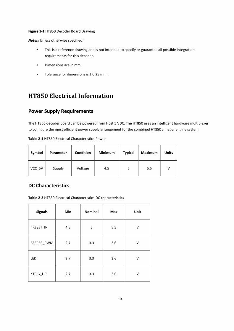
Figure 2-1 HT850 Decoder Board Drawing
Notes: Unless otherwise specified:
• This is a reference drawing and is not intended to specify or guarantee all possible integration
requirements for this decoder.
• Dimensions are in mm.
• Tolerance for dimensions is ± 0.25 mm.
HT850 Electrical Information
Power Supply Requirements
The HT850 decoder board can be powered from Host 5 VDC. The HT850 uses an intelligent hardware multiplexer
to configure the most efficient power supply arrangement for the combined HT850 /imager engine system
Table 2-1 HT850 Electrical Characteristics-Power
Symbol Parameter Condition Minimum Typical Maximum Units
VCC_5V Supply Voltage 4.5 5 5.5 V
DC Characteristics
Table 2-2 HT850 Electrical Characteristics-DC characteristics
Signals Min Nominal Max Unit
nRESET_IN 4.5 5 5.5 V
BEEPER_PWM 2.7 3.3 3.6 V
LED 2.7 3.3 3.6 V
nTRIG_UP 2.7 3.3 3.6 V
11
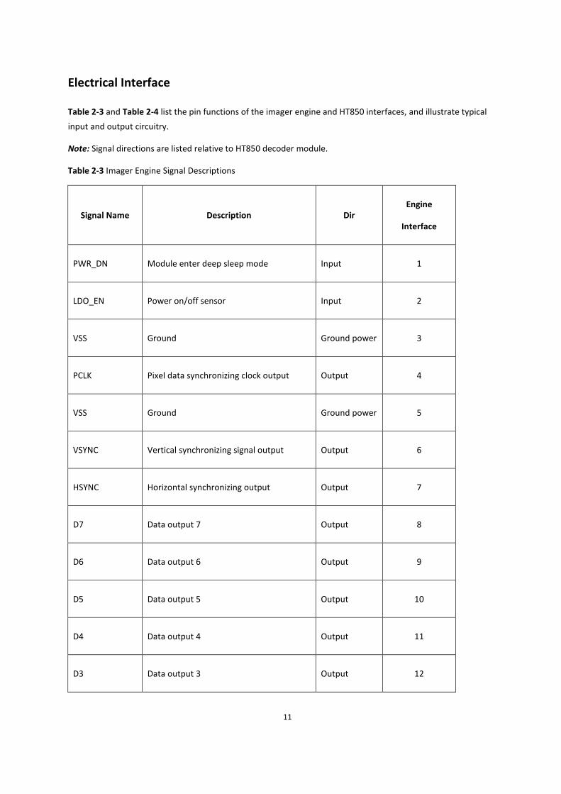
Electrical Interface
Table 2-3 and Table 2-4 list the pin functions of the imager engine and HT850 interfaces, and illustrate typical
input and output circuitry.
Note: Signal directions are listed relative to HT850 decoder module.
Table 2-3 Imager Engine Signal Descriptions
Signal Name Description Dir
Engine
Interface
PWR_DN Module enter deep sleep mode Input 1
LDO_EN Power on/off sensor Input 2
VSS Ground Ground power 3
PCLK Pixel data synchronizing clock output Output 4
VSS Ground Ground power 5
VSYNC Vertical synchronizing signal output Output 6
HSYNC Horizontal synchronizing output Output 7
D7 Data output 7 Output 8
D6 Data output 6 Output 9
D5 Data output 5 Output 10
D4 Data output 4 Output 11
D3 Data output 3 Output 12

12
D2 Data output 2 Output 13
D1 Data output 1 Output 14
D0 Data output 0 Output 15
VSS Ground Ground power 16
MCLK Main clock input Input 17
VSS Ground Ground power 18
I2C_SCL I2C serial bus clock Input 19
I2C_SDA I2C serial bus data Bi-directional 20
LED_PWR_EN1 Flash LED control 1 Input 21
LED_PWR_EN0 Flash LED control 0 Input 22
AIM_PWR_EN Aimer LED control Input 23
NC NC NC 24
VCC_SENSOR_IO Sensor IO power 1.8V or 2.8V 25
VCC_SENSOR Sensor analog power 2.8V or 3.3V 26
VCC_SENSOR Sensor analog power 2.8V or 3.3V 27
VSS Ground Ground power 28
VSS Ground Ground power 29
13
VCC_ILLUM Flash & Aimer LED power 3.3V 30
VCC_ILLUM Flash & Aimer LED power 3.3V 31
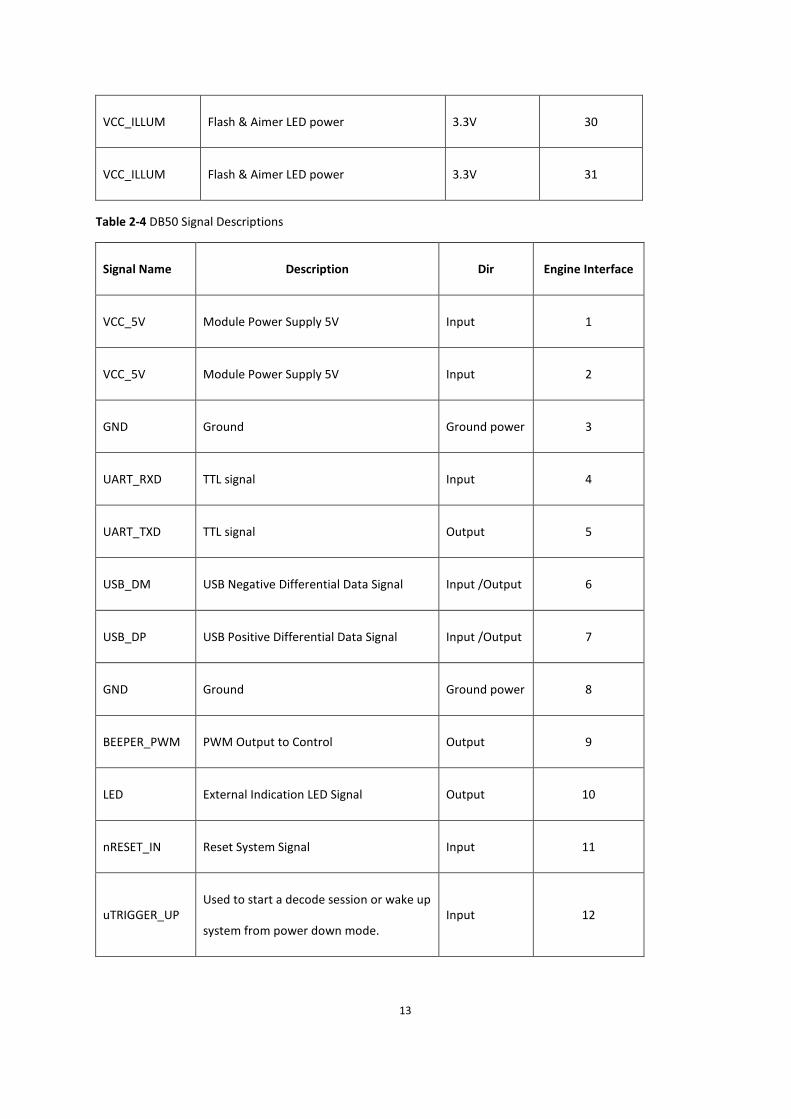
Table 2-4 DB50 Signal Descriptions
Signal Name Description Dir Engine Interface
VCC_5V Module Power Supply 5V Input 1
VCC_5V Module Power Supply 5V Input 2
GND Ground Ground power 3
UART_RXD TTL signal Input 4
UART_TXD TTL signal Output 5
USB_DM USB Negative Differential Data Signal Input /Output 6
USB_DP USB Positive Differential Data Signal Input /Output 7
GND Ground Ground power 8
BEEPER_PWM PWM Output to Control Output 9
LED External Indication LED Signal Output 10
nRESET_IN Reset System Signal Input 11
uTRIGGER_UP Used to start a decode session or wake up
system from power down mode. Input 12

14
Technical Specifications
Table 2-5 provides the technical specifications for the HT850 decoder. Note that current draw figures are valid for
a HT850 with an attached IA200 imager engine.
Table 2-5 HT850 Decoder Technical Specifications at 23°C
Item Description
Power Requirements: Supply currents listed below are typical values in mA, RMS, at
nominal supply voltage unless otherwise specified.
Host Supply 5V:
Supply Voltage 5 V +/- 0.5 V
Idle Current 25.6 mA
Operating Current 80.0 mA
Peak Current 190.0 mA
Maximum Power Supply Noise 100 mVp-p - bar code and image capture applications,
Start Up Time
From Power On
TTL: 1052 ms
USB : Host dependent
Baud Rate 300,600,1200,2400,4800,9600, 19200, 38400, 57600, 115200
Dimensions 39.0 mm x 20.0 mm x 4.1 mm
Typical Interface Board Circuit
Figure 2-2 shows the typical circuit for signal of LED. Figure 2-3 shows the typical circuit for signal of
BEEPER_PWM. Figure 2-4 shows the typical circuit for signal of nRESET_IN. Figure 2-5 shows the typical circuit for
signal of uTRIG_UP.

15
Figure 2-2 The typical circuit for signal of LED Figure 2-3 The typical circuit for signal of BEEPER_PWM
S1
11
22 3
3
44
Q2
D
G
S
GND
Q1
D
G
S
GND
nRESET_IN
R1100KR0402
R2100KR0402
GND
C20.1UC0402
GND
VDD_5V
Figure 2-4 The typical circuit for signal of nRESET_IN
C50.1UC0402
VDD_3V3
GND
R9100KR0402
GND
uTRIG_UPS2
11
22 3
3
44
Figure 2-5 The typical circuit for signal of uTRIG_UP

16
CHAPTER 3 ACCESSORIES
The accessories of HT850 are listed below:
1. 12 Pin Connector for connecting HT850 to a host,
2. 31 Pin Connector for connecting HT850 to imager engine(e.g. IA200).
The drawings of the two connectors is shown by the following figures: Figure 3-1, Figure 3-2, Figure 3-3 and Figure
3-4.

17
¼
Figure 3-1 12-Pin connector(TXGA)
¼

18
Figure 3-2 12-Pin connector(TXGA),Continued¼

19
Figure 3.3 31-Pin connector(Molex)
¼
¼

20
¼
Figure 3-4 31-Pin connector(Molex), continued
¼
¼
¼
21
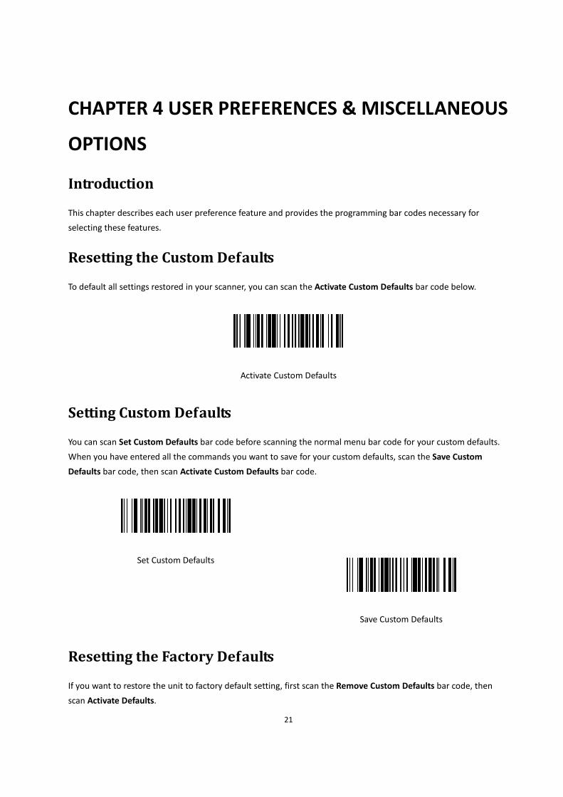
CHAPTER 4 USER PREFERENCES & MISCELLANEOUS
OPTIONS
Introduction
This chapter describes each user preference feature and provides the programming bar codes necessary for
selecting these features.
Resetting the Custom Defaults
To default all settings restored in your scanner, you can scan the Activate Custom Defaults bar code below.
Activate Custom Defaults
Setting Custom Defaults
You can scan Set Custom Defaults bar code before scanning the normal menu bar code for your custom defaults.
When you have entered all the commands you want to save for your custom defaults, scan the Save Custom
Defaults bar code, then scan Activate Custom Defaults bar code.
Set Custom Defaults
Save Custom Defaults
Resetting the Factory Defaults
If you want to restore the unit to factory default setting, first scan the Remove Custom Defaults bar code, then
scan Activate Defaults.

22
Remove Custom Defaults
Activate Defaults
Suppress Power-up Beeps
To select whether or not to suppress the decoder’s power-up beeps, you can scan a bar code below.
Default =Power Up Beeper On Scanner.
Power Up Beeper Off
*Power Up Beeper On
Beep on <BEL>
When this function is enabled, the decoder issues a beep when it detects a <BEL> character on the serial line.
<BEL> gains a user's attention to an illegal entry or other important event.
Default=Beep On BEL Off
*Beep on BEL Off
Beep on BEL On
23
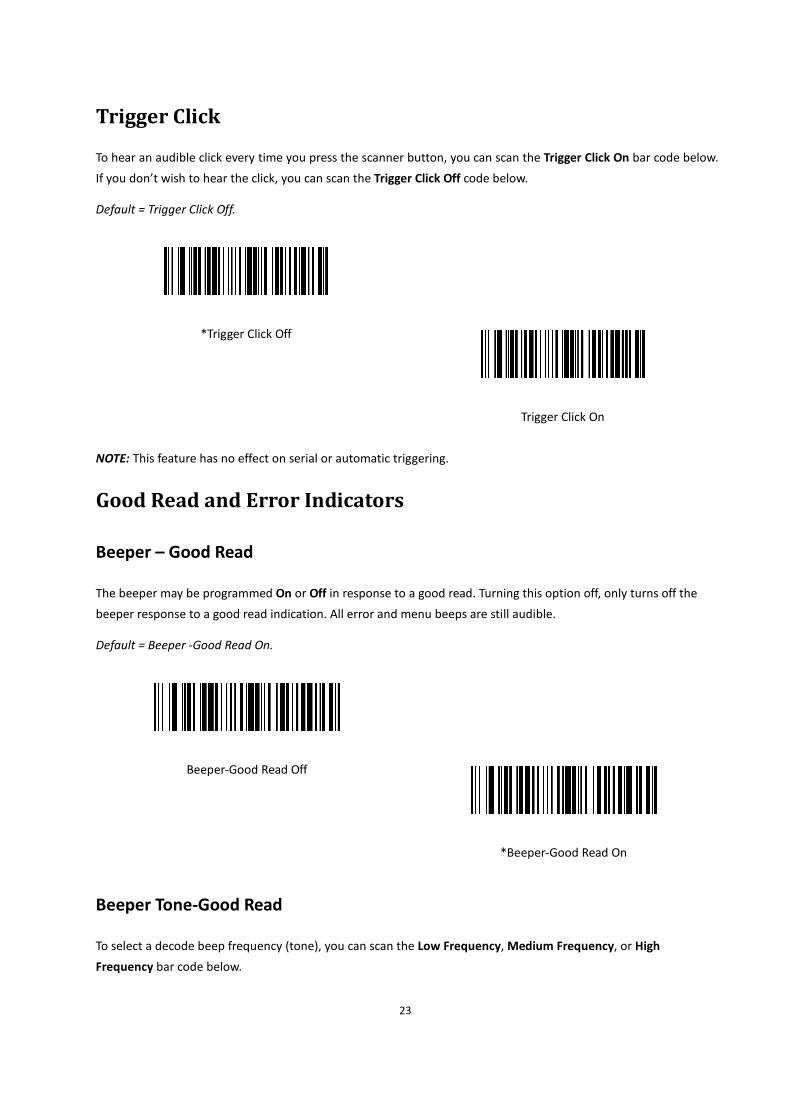
Trigger Click
To hear an audible click every time you press the scanner button, you can scan the Trigger Click On bar code below.
If you don’t wish to hear the click, you can scan the Trigger Click Off code below.
Default = Trigger Click Off.
*Trigger Click Off
Trigger Click On
NOTE: This feature has no effect on serial or automatic triggering.
Good Read and Error Indicators
Beeper – Good Read
The beeper may be programmed On or Off in response to a good read. Turning this option off, only turns off the
beeper response to a good read indication. All error and menu beeps are still audible.
Default = Beeper -Good Read On.
Beeper-Good Read Off
*Beeper-Good Read On
Beeper Tone-Good Read
To select a decode beep frequency (tone), you can scan the Low Frequency, Medium Frequency, or High
Frequency bar code below.

24
Default =Low Frequency (800 Hz).
*Low Frequency(800 Hz)
Medium Frequency(1600 Hz)
High Frequency(3200 Hz)
Beeper Tone-User Specified Setting
If you want to set your specified beep frequency (tone), scan the bar code below, then set the frequency (from
400-9,000 Hz) by scanning digits from the APPENDIX B Programming Number, then scanning Save.
Beeper Tone- User Specified Setting
Beeper Volume-Good Read
To select a beeper volume, you can scan the Low Volume, Medium Volume, or High Volume bar code below.
Default =High Volume.

25
Off
Low Volume
Medium Volume
*High Volume
Beeper Duration-Good Read
To select the duration for the beeper, you can scan one of the following bar codes.
Default =Normal Beep.
* Normal Beep
Short Beep
Number of Good Decode Beeps- Good Read
The number of beeps in response to a good decode can be programmed from bar codes as below .The same
number of beeps will be applied to both the beeper and LED in response to a good decode.
For example: if you select 2 beeps, there will be 2 beeps and 2 LED flashes in response to a good decode. The
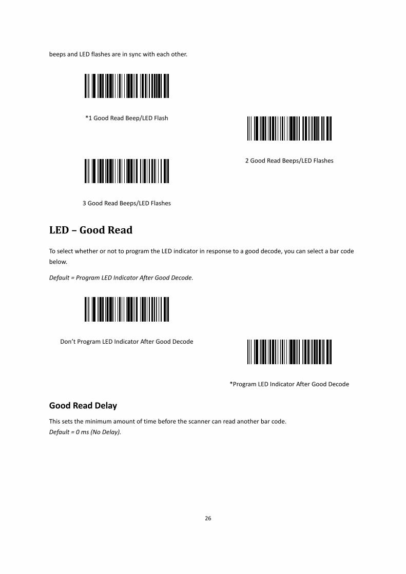
26
beeps and LED flashes are in sync with each other.
*1 Good Read Beep/LED Flash
2 Good Read Beeps/LED Flashes
3 Good Read Beeps/LED Flashes
LED – Good Read
To select whether or not to program the LED indicator in response to a good decode, you can select a bar code
below.
Default = Program LED Indicator After Good Decode.
Don’t Program LED Indicator After Good Decode
*Program LED Indicator After Good Decode
Good Read Delay
This sets the minimum amount of time before the scanner can read another bar code.
Default = 0 ms (No Delay).

27
*No Delay
Short Delay(500 ms)
Medium Delay(1000 ms)
Long Delay(1500 ms)
Manual Trigger Mode
When in manual trigger mode, the scanner scans until a bar code is read, or until the button is released.
Default = Manual Trigger-Normal.
*Manual Trigger - Normal
LED Illumination - Manual Trigger
If you wish to set the illumination LED brightness, scan one of the barcodes below. This sets the LED illumination
for the scanner when the trigger is pressed. Default = High.
Note: The LEDs are like a flash on a camera. The lower the ambient light in the room, the brighter the LEDs need to
be so the scanner can “see” the bar codes.

28
Low
*High
Aim Mode
It sets the aim illumination for the scanner when the trigger is pressed.
Default = Aim Mode On.
Aim Mode Off
*Aim Mode On
Presentation Mode
Presentation Mode uses ambient light to detect bar codes. When no bar code is presented to the scanner, the LED
dims. When a bar code is presented to the scanner, the LED brightens to read the code.
Note: If the light level in the room is not high enough, Presentation Mode may not work properly.
Presentation Mode
29
Idle Illumination - Presentation Mode
Scan one of the bar codes below to set the LED illumination for the scanner when it is in an idle state in
Presentation Mode.
Default = Low.
Note: If you use one of the lower Idle Illumination settings, and there is not enough ambient light, the scanner may
have difficulty detecting when a bar code is presented to it. If the scanner has difficulty “waking up” to read bar
codes, you may need to set the Idle Illumination to a brighter setting.
*Low
High
Presentation Sensitivity
Presentation Sensitivity is a numeric range that increases or decreases the scanner's reaction time to bar code
presentation. To set the sensitivity, scan the Sensitivity bar code, then scan the degree of sensitivity (from 0-20)
from the inside back cover, and Save. 0 is the most sensitive setting, and 20 is the least sensitive.
Default = 4.
Sensitivity

30
Presentation Centering
Use Presentation Centering to narrow the scanner’s field of view when it is in the stand to make sure the scanner
reads only those bar codes intended by the user. For instance, if multiple codes are placed closely together,
Presentation Centering will insure that only the desired codes are read.
Note: To adjust centering when the scanner is hand-held, see Manual Trigger Centering . If a bar code is not
touched by a predefined window, it will not be decoded or output by the scanner. If Presentation Centering is
turned on by scanning Presentation Centering On, the scanner only reads codes that pass through the centering
window you specify using the Top of Presentation Centering Window, Bottom of Presentation Centering Window,
Left, and Right of Presentation Centering Window bar codes.
In the example below, the white box is the centering window. The centering window has been set to 20% left, 30%
right, 8% top, and 25% bottom. Since Bar Code 1 passes through the centering window, it will be read. Bar Code 2
does not pass through the centering window, so it will not be read.
Note: A bar code needs only to be touched by the centering window in order to be read. It does not need to pass
completely through the centering window.
Scan Presentation Centering On, then scan one of the following bar codes to change the top, bottom, left, or right
of the centering window. Then scan the percent you want to shift the centering window using digits on the inside
back cover of this manual. Scan Save.
Default Presentation Centering = 40% for Top and Left, 60% for Bottom and Right.

31
*Presentation Centering Off
Presentation Centering On
Top of Presentation Centering Window
Bottom of Presentation Centering Window
Left of Presentation Centering Window
Right of Presentation Centering Window
Mobile Phone/Display Mode
This mode improves bar code reading performance with target bar codes displayed on mobile phones and
electronic displays.
Hand Held Scanning - Mobile Phone
Presentation Scanning - Mobile Phone

32
Note: To turn off Mobil Phone Read Mode, scan the Manual Trigger Mode bar Code.
Hands Free Time-Out
The Scan Stand and Presentation Modes are referred to as “hands free” modes. If the scanner’s button is pressed
when using a hands free mode, the scanner changes to manual trigger mode. You can set the time the scanner
should remain in manual trigger mode by setting the Hands Free Time-Out. Once the time-out value is reached, (if
there have been no further button presses) the scanner reverts to the original hands free mode. Scan the Hands
Free Time-Out bar code, then scan the time-out duration (from 0-300,000 milliseconds) from the inside back cover,
and Save.
Default =5,000 ms.
Hands Free Time-Out
Reread Delay
Use this option in Presentation Mode to prevent multiple reads of a symbol left in the decoder’s field of view.
The timeout begins when you remove the symbol from the field of view.
Default = Medium(1000 ms).
No Delay
Short (500 ms)
* Medium (1000 ms)
Extra Long(2000 ms)

33
User-Specified Reread Delay
If you want to set your own length for the reread delay, scan the bar code below, then set the delay (from 0-30,000
milliseconds) by scanning digits from the inside back cover, then scanning Save.
User-Specified Reread Delay
Manual Trigger Centering
Use Centering to narrow the scanner’s field of view to make sure that when the scanner is hand-held, it reads only
those bar codes intended by the user. For instance, if multiple codes are placed closely together, centering will
insure that only the desired codes are read.
Note: To adjust centering when the scanner is in the stand, see Presentation Centering .
If a bar code is not touched by a predefined window, it will not be decoded or output by the scanner. If centering is
turned on by scanning Centering On, the scanner only reads codes that pass through the centering window you
specify using the Top of Centering Window, Bottom of Centering Window, Left, and Right of Centering Window
bar codes.
In the example below, the white box is the centering window. The centering window has been set to 20% left, 30%
right, 8% top, and 25% bottom. Since Bar Code 1 passes through the centering window, it will be read. Bar Code 2
does not pass through the centering window, so it will not be read.
Note: A bar code needs only to be touched by the centering window in order to be read. It does not need to pass
completely through the centering window.

34
Scan Centering On, then scan one of the following bar codes to change the top, bottom, left, or right of the
centering window. Then scan the percent you want to shift the centering window using digits on the inside back
cover of this manual. Scan Save.
Default Centering = 40% for Top and Left, 60% for Bottom and Right.
* Manual Trigger Centering Off
Manual Trigger Centering On
Top of Manual Trigger Centering Window
Bottom of Manual Trigger Centering Window
Left of Manual Trigger Centering Window
Right of Manual Trigger Centering Window
Video Reverse
Video Reverse Off :Disable Video Reverse.
Video Reverse Only: Read only inverted bar codes.
Video Reverse and Standard Bar Codes :Read both types of codes.
Note: After scanning Video Reverse Only, menu bar codes cannot be read. You must scan Video Reverse Off or
Video Reverse and Standard Bar Codes in order to read menu bar codes.
Note: Images downloaded from the unit are not reversed. This is a setting for decoding only.

35
* Video Reverse Off
Video Reverse and Standard Bar Codes
Video Reverse Only
Working Orientation
Some bar codes are direction-sensitive. For example, KIX codes and OCR can misread when scanned sideways or
upside down. Use the working orientation settings if your direction-sensitive codes will not usually be presented
upright to the scanner.
Default = Upright.

36
*Upright
Vertical, Bottom to Top
Upside Down
Vertical, Top to Bottom
Show Revision
Scan the bar code below to output the current software revision, serial number, and other product information.
Show Revision
Resetting the Factory Defaults
If you aren’t sure what programming options are in your scanner, or you’ve changed some options and want to
restore the scanner to factory default settings, first scan the Remove Custom Defaults bar code, then scan
Activate Custom Defaults. This resets the scanner to the factory default settings. NOTE: This selection erases all
your settings and resets to the original factory defaults and disables all plugins.
Remove Custom Defaults
Activate Custom Defaults

37
CHAPTER 5 USB INTERFACE
USB Serial
Scan the following code to program the scanner to emulate a regular RS232-based COM Port. If you are using a
Microsoft® Windows® PC, you will need to a driver from the IA Lab. The driver will use the next available COM Port
number.
USB Serial
Note: No extra configuration (e.g., baud rate) is necessary.
ACK/NAK Mode
*ACK/NAK Mode Off
ACK/NAK Mode On
USB PC or Macintosh Keyboard
Scan one of the following codes to program the scanner for USB PC Keyboard or USB Macintosh Keyboard.
Scanning these codes also adds a CR and LF.
USB Keyboard(PC)
USB Keyboard(Mac)
USB Japanese Keyboard(PC)
38
Keyboard Country Layout
Scan the appropriate country code below to program the keyboard layout for your country or language. As a
general rule, the following characters are supported, but need special care for countries other than the United
States: @ | $ # [ ] = / ‘ \ < > ~
*United States
United States(Dvorak)
United States(Dvorak left)
United States(Dvorak right)
United States(International)
Albania
Azeri(Cyrillic)
Azeri (Latin)

39
Belarus
Belgium
Bosnia
Brazil
Brazil (MS)
Bulgaria (Cyrillic)
Bulgaria (Latin)
Canada (French legacy)
Canada (French)
Canada (Multilingual)

40
Croatia
Czech
Czech (Programmers)
Czech (QWERTY)
Czech (QWERTZ)
Denmark
Dutch (Netherlands)
Estonia
Faeroese
Finland

41
France
Gaelic
Germany
Greek
Greek (220 Latin)
Greek (220)
Greek (319 Latin)
Greek (319)
Greek (Latin)
Greek (MS)

42
Greek (Polytonic)
Hebrew
Hungarian (101 key)
Hungary
Iceland
Irish
Italian (142)
Italy
Japan ASCII
Kazakh

43
Kyrgyz (Cyrillic)
Latin America
Latvia
Latvia (QWERTY)
Lithuania
Lithuania (IBM)
Macedonia
Malta
Mongolian (Cyrillic)
Norway

44
Poland
Polish (214)
Polish (Programmers)
Portugal
Romania
Russia
Russian (MS)
Russian (Typewriter)
SCS
Serbia (Cyrillic)

45
Serbia (Latin)
Slovakia
Slovakia (QWERTY)
Slovakia (QWERTZ)
Slovenia
Spain
Spanish variation
Sweden
Switzerland (French)
Switzerland (German)

46
Tatar
Turkey F
Turkey Q
Ukrainian
United Kingdom
Uzbek (Cyrillic)
Keyboard Style
This programs keyboard styles, such as Caps Lock and Shift Lock. If you have used Keyboard Conversion settings,
they will override any of the following Keyboard Style settings.
Default = Regular.
Regular is used when you normally have the Caps Lock key off.
* Regular
Caps Lock is used when you normally have the Caps Lock key on.

47
Caps Lock
Shift Lock is used when you normally have the Shift Lock key on (not common to U.S. keyboards).
Shift Lock
Automatic Caps Lock is used if you change the Caps Lock key on and off. The software tracks and reflects if you
have Caps Lock on or off . This selection can only be used with systems that have an LED that notes the Caps Lock
status .
Automatic Caps Lock
Autocaps via NumLock bar code should be scanned in countries (e.g., Germany, France) where the Caps Lock key
cannot be used to toggle Caps Lock. The NumLock option works similarly to the regular Autocaps, but uses the
NumLock key to retrieve the current state of the Caps Lock.
Autocaps via NumLock
Emulate External Keyboard should be scanned if you do not have an external keyboard (IBM AT or equivalent).
Emulate External Keyboard
Note: After scanning the Emulate External Keyboard bar code, you must power cycle your computer.
Keyboard Conversion
Alphabetic keyboard characters can be forced to be all upper case or all lowercase. So if you have the following bar
48
code: “1a2B3c4D5e,” you can make the output “1A2B3C4D5E” by scanning Convert All Characters to Upper Case,
or to “1a2b3c4d5e” by scanning Convert All Characters to Lower Case.
These settings override Keyboard Style selections.
Note: If your interface is a keyboard wedge, first scan the menu code for Automatic Caps Lock . Otherwise, your
output may not be as expected.
Default = Keyboard Conversion Off.
* Keyboard Conversion Off
Convert All Characters to Upper Case
Convert All Characters to Lower Case
Control Character Output
This selection sends a text string instead of a control character. For example, when the control character for a
carriage return is expected, the output would display [CR] instead of the ASCII code of 0D. Refer to APPENDIX D
ASCII Conversion Chart. Only codes 00 through 1F are converted (the first column of the chart).
Note: Control + ASCII Mode overrides this mode.
Default = Off.
* Control Character Output Off
Control Character Output On
Keyboard Modifiers
This modifies special keyboard features, such as CTRL+ ASCII codes and Turbo Mode.
49
Control + ASCII Mode On: The scanner sends key combinations for ASCII control characters for values 00-1F.
Windows is the preferred mode. All keyboard country codes are supported.
DOS mode is a legacy mode, and it does not support all keyboard country codes. New users should use the
Windows mode. Refer to APPENDIX A Interface Keys for CTRL+ ASCII Values.
Windows Mode Prefix/Suffix Off: The scanner sends key combinations for ASCII control characters for values
00-1F, but it does not translate any prefix or suffix information.
Default = Control + ASCII Mode Off.
* Control + ASCII Mode Off
DOS Mode Control + ASCII Mode On
Windows Mode Control + ASCII Mode On
Windows Mode Prefix/Suffix Off
50
CHAPTER 6 SERIAL INTERFACE
Introduction
This chapter describes how to set up the decoder with a serial host. The DB50 supports TTL signal. So the serial
interface which converts TTL signal to RS232 signal connects the decoder to point-of-sale devices, host computers,
or other devices with an available serial port (e.g., com port).
RS232 Serial Port
The RS232 Interface bar code is used when connecting to the serial port of a PC or terminal. The following RS232
Interface bar code also programs a carriage return (CR) and a line feed (LF) suffix, baud rate, and data format as
indicated below. It also changes the trigger mode to manual.
RS232 Interface
Parameter Factory Default
Serial Communication Standard RS232
Baud Rate 115200
Parity Check None
Data Bits 8
Stop Bits 1
Hardware Flow Control None
Baud Rate
Baud rate is the number of bits of data transmitted per second. Set the decoder's baud rate to match the baud rate
setting of the host device. Otherwise, data may not reach the host device or may reach it in distorted form.
Default=Band Rate 115200

51
Band Rate 300
Band Rate 600
Band Rate 1200
Band Rate 2400
Band Rate 4800
Band Rate 9600
Band Rate 19200
Band Rate 38400
Band Rate 57600
*Band Rate 115200

52
RS232 Receiver Time-Out
The DB50 runs normal until the RS232 Receiver Time-Out expires and the DB50 will enter in Power Down mode
which the DB50 power consumption is none . A manual trigger resets the time-out and wake up the DB50. The
receiver Change the RS232 receiver time-out by scanning the bar code below, then scanning digits from the inside
back cover of this manual, then scanning Save. The range is 0 to 300 seconds.
Default = 0 seconds (no time-out - always on).
RS232 Receiver Time-Out
53
CHAPTER 7 SYMBOLOGIES
Introduction
This chapter describes symbology features and provides the programming bar codes for selecting these features. If
the default values suit requirements, programming is not necessary.
All Symbologies
All Symbologies Off: To disable all symbologies, scan the All Symbologies Off bar code. This is useful when
enabling only a few code types.
All Symbologies On: To enable all symbologies, scan the All Symbologies On bar code.
All Symbologies Off
All Symbologies On
UPC/EAN
Default All UPC-A Settings
To default all UPC-A Settings, scan the bar code below.
Default All UPC-A Settings

54
Enable/Disable UPC-A
To enable or disable UPC-A, scan the appropriate bar code below.
Default =UPC-A On.
UPC-A Off
*UPC-A On
Note: When UPC-A Off is scanned, UPC-A bar codes are transmitted as EAN-13.
UPC-A Check Digit
The check digit is the last character of the symbol used to verify the integrity of the data. Scan the appropriate bar
code below to transmit the bar code data with or without the UPC-A check digit. It is always verified to guarantee
the integrity of the data.
Default= UPC-A check digit On.
UPC-A check digit Off
*UPC-A check digit On
UPC-A Number System
The numeric system digit of a U.P.C. symbol is normally transmitted at the beginning of the scanned data. To select
whether or not to transmit the number system, you can scan one of the bar codes below.

55
Default = UPC-A Number System On.
UPC-A Number System Off
*UPC-A Number System On
UPC-A Addenda
This selection adds 2 or 5 digits to the end of all scanned UPC-A data.
Default = Off for both 2 Digit and 5 Digit Addenda.
* 2 Digit Addenda Off
2 Digit Addenda On
* 5 Digit Addenda Off
5 Digit Addenda On
UPC-A Addenda Required
When UPC-A Addenda Required bar code is scanned, the scanner only can read UPC-A bar codes that have
addenda.
Default = UPC-A Addenda Not Required.

56
* UPC-A Addenda Not Required
UPC-A Addenda Required
UPC-A Addenda Separator
UPC-A Addenda Separator On: There is a space between the data from the bar code and the data from the
addenda.
UPC-A Addenda Separator Off: There is no space between the data from the bar code and the data from the
addenda.
Default = UPC-A Addenda Separator On.
UPC-A Addenda Separator Off
* UPC-A Addenda Separator On
UPC-A/EAN-13 with Extended Coupon Code
To enable or disable UPC-A and EAN-13 with Extended Coupon Code, you can scan the bar codes below.
Off: Treats Coupon Codes and Extended Coupon Codes as single bar codes.
Allow Concatenation: The scanner sees the coupon code and the extended coupon code in a single read, it
transmits both as separate symbologies. Otherwise, it transmits the first coupon code it reads.
Require Concatenation: The scanner must see and read the coupon code and extended coupon code in a single
read to transmit the data. No data is output unless both codes are read.
Default = Off.

57
* Off
Require Concatenation
Allow Concatenation
Coupon GS1 DataBar Output
If you scan coupons that have both UPC and GS1 DataBar codes, you may wish to scan and output only the data
from the GS1 DataBar code.
To scan and output only the GS1 DataBar code data, you can scan the GS1 Output On code below.
Default = GS1 Output Off.
*GS1 Output Off
GS1 Output On
Default All UPC-E0 Settings
Most U.P.C. bar codes lead with the 0 number system. To read these codes, use the UPC-E0 On selection.
To default all UPC-E0 Settings, scan the bar code below.

58
Default all UPC-E0 Settings
Enable/Disable UPC-E0
To enable or disable UPC-E, scan the appropriate bar code below.
Default =UPC-E0 On.
UPC-E0 Off
* UPC-E0 On
UPC-E0 Expand
UPC-E Expand expands the UPC-E code to the 12 digit, UPC-A format.
Default = UPC-E0 Expand Off.
*UPC-E0 Expand Off
UPC-E0 Expand On

59
UPC-E0 Number System
The numeric system digit of a U.P.C. symbol is normally transmitted at the beginning of the scanned data. To select
whether or not to transmit the number system, you can scan one of the bar codes below.
Default = UPC-E0 Number System On.
UPC-E0 Number System Off
*UPC-E0 Number System On
UPC-E0 Addenda
This selection adds 2 or 5 digits to the end of all scanned UPC-E data.
Default = Off for both 2 Digit and 5 Digit Addenda.
* 2 Digit Addenda Off
2 Digit Addenda On
* 5 Digit Addenda Off
5 Digit Addenda On
60
UPC-E0 Addenda Required
When UPC-E0 Addenda Required bar code is scanned, the scanner only can read UPC-E0 bar codes that have
addenda.
Default =UPC-E0 Addenda Not Required.
* UPC-E0 Addenda Not Required
UPC-E0 Addenda Required
UPC-E0 Addenda Separator
UPC-E0 Addenda Separator On: There is a space between the data from the bar code and the data from the
addenda.
UPC-E0 Addenda Separator Off: There is no space between the data from the bar code and the data from the
addenda.
Default =UPC-E0 Addenda Separator On.
UPC-E0 Addenda Separator Off
*UPC-E0 Addenda Separator On
Transmit UPC-E0 Check Digit
The check digit is the last character of the symbol used to verify the integrity of the data. Scan the appropriate bar
code below to transmit the bar code data with or without the UPC-E0 check digit. It is always verified to guarantee
the integrity of the data.

61
Default= UPC-E0 Check Digit On.
UPC-E0 Check Digit Off
*UPC-E0 Check Digit On
Enable/Disable UPC-E1
To enable or disable UPC-E1, scan the appropriate bar code below. Default= UPC-E1 Off.
NOTE: UPC-E1 is not a UCC (Uniform Code Council) approved symbology.
* UPC-E1 Off
UPC-E1 On
Default All EAN/JAN-8 Settings
To default all EAN/JAN-8 Settings, scan the bar code below.
Default all EAN/JAN-8 Settings
Enable/Disable EAN/JAN-8
To enable or disable EAN-8/JAN-8, scan the appropriate bar code below.
62
Default =EAN/JAN-8 On.
EAN/JAN-8 Off
*EAN/JAN-8 On
EAN/JAN-8 Check Digit
The check digit is the last character of the symbol used to verify the integrity of the data.
Scan the appropriate bar code below to transmit the bar code data with or without the EAN/JAN-8 check digit. It is
always verified to guarantee the integrity of the data.
Default = EAN/JAN-8 Check Digit On.
EAN/JAN-8 Check Digit Off
*EAN/JAN-8 Check Digit On
EAN/JAN-8 Addenda
This selection adds 2 or 5 digits to the end of all scanned EAN/JAN-8 data.
Default = Off for both 2 Digit and 5 Digit Addenda.

63
* 2 Digit Addenda Off
2 Digit Addenda On
* 5 Digit Addenda Off
5 Digit Addenda On
EAN/JAN-8 Addenda Required
When EAN/JAN-8 Addenda Required bar code is scanned, the scanner only can read EAN/JAN-8 bar codes that
have addenda.
Default =EAN/JAN-8 Addenda Not Required.
* EAN/JAN-8 Addenda Not Required
EAN/JAN-8 Addenda Required
EAN/JAN-8 Addenda Separator
EAN/JAN-8 Addenda Separator On: There is a space between the data from the bar code and the data from the
addenda.

64
EAN/JAN-8 Addenda Separator Off: There is no space between the data from the bar code and the data from the
addenda.
Default =EAN/JAN-8 Addenda Separator On.
EAN/JAN-8 Addenda Separator Off
* EAN/JAN-8 Addenda Separator On
Default All EAN/JAN-13 Settings
To default all EAN/JAN-13 Settings, scan the bar code below.
Default all EAN/JAN-13 Settings
Enable/Disable EAN/JAN-13
To enable or disable EAN-13/JAN-13, scan the appropriate bar code below.
Default =EAN/JAN-13 Off.
*EAN/JAN-13 Off
EAN/JAN-13 On
Note: If you want to convert UPC-A bar codes to EAN-13 format, scan the UPC-A Off bar code.

65
EAN/JAN-13 Check Digit
The check digit is the last character of the symbol used to verify the integrity of the data. Scan the appropriate bar
code below to transmit the bar code data with or without the EAN/JAN-13 check digit. It is always verified to
guarantee the integrity of the data.
Default = EAN/JAN-13 Check Digit On.
EAN/JAN-13 Check Digit Off
*EAN/JAN-13 Check Digit On
EAN/JAN-13 Addenda
This selection adds 2 or 5 digits to the end of all scanned EAN/JAN-13 data.
Default = Off for both 2 Digit and 5 Digit Addenda.
* 2 Digit Addenda Off
2 Digit Addenda On
* 5 Digit Addenda Off
5 Digit Addenda On

66
EAN/JAN-13 Addenda Required
When EAN/JAN-13 Addenda Required bar code is scanned, the scanner only can read EAN/JAN-13 bar codes that
have addenda.
Default =EAN/JAN-13 Addenda Not Required.
* EAN/JAN-13 Addenda Not Required
EAN/JAN-13 Addenda Required
EAN/JAN-13 Addenda Separator
EAN/JAN-13 Addenda Separator On: There is a space between the data from the bar code and the data from the
addenda.
EAN/JAN-13 Addenda Separator Off: There is no space between the data from the bar code and the data from the
addenda.
Default = EAN/JAN-13 Addenda Separator On.
EAN/JAN-13 Addenda Separator Off
* EAN/JAN-13 Addenda Separator On
Note: If you want to enable or disable EAN13 with Extended Coupon Code, refer to UPC-A/EAN-13 with Extended
Coupon Code.
ISBN Translate
ISBN Translate Off: The decoder reports Bookland data (starting with either 978 or 979) as EAN-13 in 13-digit
67
format to meet the 2007 ISBN-13 protocol.
ISBN Translate On: EAN-13 Bookland symbols are translated into their equivalent ISBN number format.
Default=ISBN Translate Off.
* ISBN Translate Off
ISBN Translate On
Code 128
Default All Code 128 Settings
To default all Code 128 Settings, scan the bar code below.
Default all Code 128 Settings
Enable/Disable Code 128
To enable or disable Code 128, scan the appropriate bar code below.
Default =Code 128 On.
Code 128 Off
*Code 128 On
68
ISBT 128 Concatenation
ISBT Concatenation Off: The decoder does not concatenate pairs of ISBT codes it encounters.
ISBT Concatenation On: There must be two ISBT codes in order for the decoder to decode and perform
concatenation. The decoder does not decode single ISBT symbols.
The use of ISBT formats requires a paid license. The ISBT 128 Application Specification describes 1) the critical data
elements for labeling blood products, 2) the current recommendation to use Code 128 due to its high degree of
security and its space-efficient design, 3) a variation of Code 128 that supports concatenation of neighboring
symbols, and 4) the standard layout for bar codes on a blood product label. Use the bar codes below to turn
concatenation on or off.
Default =ISBT 128 Off.
* ISBT 128 Off
ISBT 128 On
Code 128 Message Length
To change the message length of Code 128, you can scan the bar codes below.
Minimum and Maximum lengths = 0-80.
Minimum Default = 0, Maximum Default = 80.
Minimum Message Length
Maximum Message Length
69
Code 128 Append
This function allows the scanner to append the data from several Code 128 bar codes together before transmitting
them to the host computer. When the scanner encounters a Code 128 bar code with the append trigger
character(s), it buffers Code 128 bar codes until it reads a Code 128 bar code that does not have the append trigger.
The data is then transmitted in the order in which the bar codes were read (FIFO).
Default =Code 128 Append Off.
* Code 128 Append Off
Code 128 Append On
Code 128 Code Page32
Code pages define the mapping of character codes to characters. If the data received does not display with the
proper characters, it may be because the bar code being scanned was created using a code page that is different
from the one the host program is expecting. If this is the case, scan the bar code below, select the code page with
which the bar codes were created, and scan the value and the Save bar code from the APPENDIX B Programming
Number on the inside the back cover of this manual. The data characters should then appear properly.
Code 128 Code Page
Default All GS1-128 Settings
To default all GS1-128 Settings, scan the bar code below.

70
Default all GS1-128 Settings
Enable/Disable GS1-128
To enable or disable GS1-128, scan the appropriate bar code below.
Default =GS1-128 On.
GS1-128 Off
*GS1-128 On
GS1-128 Message Length
To change the message length of GS1-128, you can scan the bar codes below. Minimum and Maximum lengths =
1-80.
Minimum Default = 1, Maximum Default = 80.
Minimum Message Length
Maximum Message Length

71
Telepen
Default All Telepen Settings
To default all Telepen Settings, scan the bar code below.
Default All Telepen Settings
Enable/Disable Telepen
To enable or disable Telepen, scan the appropriate bar code below.
Default =Telepen Off.
*Telepen Off
Telepen On
Telepen Output
AIM Telepen Output: The scanner reads symbols with start/stop pattern 1 and decodes them as standard full
ASCII.
Original Telepen Output: The scanner reads symbols with start/stop pattern 1 and decodes them as compressed
numeric with optional full ASCII.
Default = AIM Telepen Output.

72
* AIM Telepen Output
Original Telepen Output
Telepen Message Length
To change the message length of Telepen, you can scan the bar codes below. Minimum and Maximum lengths =
1-60.
Minimum Default = 1, Maximum Default = 60.
Minimum Message Length
Maximum Message Length
Code 39
Default All Code 39 Settings
To default all Code 39 Settings, scan the bar code below.
Default all Code 39 Settings

73
Enable/Disable Code 39
To enable or disable Code 39, scan the appropriate bar code below.
Default =Code 39 On.
Code 39 Off
*Code 39 On
Code 39 Start/Stop Characters
Start/Stop characters identify the leading and trailing ends of the bar code. You may either transmit, or not
transmit Start/Stop characters.
Default = Don’t Transmit Start/Stop Characters.
* Don’t Transmit Start/Stop Characters
Transmit Start/Stop Characters
Code 39 Check Character
No Check Character: The scanner reads and transmits bar code data with or without a check character.
Validate, but Don’t Transmit: The unit only reads Code 39 bar codes printed with a check character, but will not
transmit the check character with the scanned data.
Validate and Transmit: The scanner only reads Code 39 bar codes printed with a check character, and will transmit
this character at the end of the scanned data.
Default = No Check Character.

74
* No Check Character
Validate and Transmit
Validate, but Don’t Transmit
Code 39 Message Length
To change the message length of Code 39, you can scan the bar codes below.
Minimum and Maximum lengths = 0-48.
Minimum Default = 0, Maximum Default = 48.
Minimum Message Length
Maximum Message Length
Code 39 Append
This function allows the scanner to append the data from several Code 39 bar codes together before transmitting
them to the host computer. When the scanner encounters a Code 39 bar code with the append trigger character(s),
it buffers Code 39 bar codes until it reads a Code 39 bar code that does not have the append trigger. The data is
then transmitted in the order in which the bar codes were read (FIFO).
Default = Code 39 Append Off.

75
* Code 39 Append Off
Code 39 Append On
Convert Code 39 to Code 32
Code 32 is a variant of Code 39 used by the Italian pharmaceutical industry. Scan the appropriate bar code below
to enable or disable converting Code 39 to Code 32.
NOTE: Code 39 must be enabled for this parameter to function.
Default =Convert Code 39 to Code 32 Off.
* Convert Code 39 to Code 32 Off
Convert Code 39 to Code 32 On
Full ASCII
Code 39 Full ASCII is a variant of Code 39 which pairs characters to encode the full ASCII character set. To enable or
disable Code 39 Full ASCII, scan the appropriate bar code below.
Default=Full ASCII Off.

76
* Full ASCII Off
Full ASCII On
Code 39 Code Page
Code pages define the mapping of character codes to characters. If the data received does not display with the
proper characters, it may be because the bar code being scanned was created using a code page that is different
from the one the host program is expecting. If this is the case, scan the bar code below, select the code page with
which the bar codes were created, and scan the value and the Save bar code from the APPENDIX B Programming
Number on the inside the back cover of this manual. The data characters should then appear properly.
Code 39 Code Page
Code 93
Default All Code 93 Settings
To default all Code 93 Settings, scan the bar code below.

77
Default all Code 93 Settings
Enable/Disable Code 93
To enable or disable Code 93, scan the appropriate bar code below.
Default =Code 93 On.
Code 93 Off
*Code 93 On
Code 93 Message Length
To change the message length of Code 93, you can scan the bar codes below. Minimum and Maximum lengths =
0-80.
Minimum Default = 0, Maximum Default = 80.
Minimum Message Length
Maximum Message Length
Code 93 Append
This function allows the scanner to append the data from several Code 93 bar codes together before transmitting

78
them to the host computer. When this function is enabled, the scanner stores those Code 93 bar codes that start
with a space (excluding the start and stop symbols), and does not immediately transmit the data. The scanner
stores the data in the order in which the bar codes are read, deleting the first space from each. The scanner
transmits the appended data when it reads a Code 93 bar code that starts with a character other than a space.
Default = Code 39 Append Off.
* Code 93 Append Off
Code 39 Append On
Code 93 Code Page
Code pages define the mapping of character codes to characters. If the data received does not display with the
proper characters, it may be because the bar code being scanned was created using a code page that is different
from the one the host program is expecting. If this is the case, scan the bar code below, select the code page with
which the bar codes were created, and scan the value and the Save bar code from the APPENDIX B Programming
Number on the inside the back cover of this manual. The data characters should then appear properly.
Code 93 Code Page
Code 11
Default All Code 11 Settings
To default all Code 11 Settings, scan the bar code below.

79
Default all Code 11 Settings
Enable/Disable Code 11
To enable or disable Code 11, scan the appropriate bar code below.
Default =Code 11 Off
*Code 11 Off
Code 11 On
Code 11 Check Digits Required
This option sets whether 1 or 2 check digits are required with Code 11 bar codes.
Default = Two Check Digits.
One Check Digit
* Two Check Digits
Code 11 Message Length
To change the message length of Code 11, you can scan the bar codes below. Mini-mum and Maximum lengths =

80
1-80.
Minimum Default = 4, Maximum Default = 80.
Minimum Message Length
Maximum Message Length
Interleaved 2 of 5 (ITF)
Default All Interleaved 2 of 5 Settings
To default all Interleaved2 of 5 Settings, scan the bar code below.
Default all Interleaved2 of 5 Settings
Enable/Disable Interleaved 2 of 5
To enable or disable Interleaved 2 of 5, scan the appropriate bar code below, and select an Interleaved 2 of 5
length from the following pages.
Default =Interleaved 2 of 5 On.
Interleaved 2 of 5 Off
*Interleaved 2 of 5 On
81
Interleaved 2 of 5Check Digit
No Check Digit: The scanner reads and transmits bar code data with or without a check digit.
Validate, but Don’t Transmit: The unit only reads Interleaved 2 of 5 bar codes printed with a check digit, but will
not transmit the check digit with the scanned data.
Validate and Transmit: The scanner only reads Interleaved 2 of 5 bar codes printed with a check digit, and will
transmit this digit at the end of the scanned data.
Default = No Check Digit.
* No Check Digit
Validate and Transmit
Validate, but Don’t Transmit
Interleaved 2 of 5 Message Length
To change the message length of Interleaved 2 of 5, you can scan the bar codes below. Mini-mum and Maximum
lengths = 2-80.
Minimum Default = 4, Maximum Default = 80.
Minimum Message Length
Maximum Message Length

82
NEC 2 of 5
Default All NEC 2 of 5 Settings
To default all NEC 2 of 5 Settings, scan the bar code.
Default all NEC 2 of 5 Settings
Enable/Disable NEC 2 of 5
To enable or disable NEC 2 of 5, scan the appropriate bar code below.
Default =NEC 2 of 5 On.
NEC 2 of 5 Off
*NEC 2 of 5 On
Check Digit
No Check Digit: The scanner reads and transmits bar code data with or without a check digit.
Validate, but Don’t Transmit: The unit only reads NEC 2 of 5 bar codes printed with a check digit, but will not
transmit the check digit with the scanned data.
Validate and Transmit: The scanner only reads NEC 2 of 5 bar codes printed with a check digit, and will transmit
this digit at the end of the scanned data.
Default = No Check Digit.
83
* No Check Digit
Validate and Transmit
Validate, but Don’t Transmit
NEC 2 of 5 Message Length
To change the message length of NEC 2 of 5, you can scan the bar codes below. Minimum and Maximum lengths =
2-80.
Minimum Default = 4, Maximum Default = 80.
Minimum Message Length
Maximum Message Length
Straight 2 of 5 Industrial (three-bar start/stop)
Default All Straight 2 of 5 Industrial Settings
To default all Straight 2 of 5 Industrial Settings, scan the bar code below.

84
Default All Straight 2 of 5 Industrial Settings
Enable/Disable Straight 2 of 5 Industrial
To enable or disable Straight 2 of 5 Industrial, scan the appropriate bar code below.
Default =Straight 2 of 5 Industrial Off.
*Straight 2 of 5 Industrial Off
Straight 2 of 5 Industrial On
Straight 2 of 5 Industrial Message Length
To change the message length of Straight 2 of 5 Industrial, you can scan the bar codes below. Minimum and
Maximum lengths = 1-48.
Minimum Default = 4, Maximum Default = 48.
Minimum Message Length
Maximum Message Length
85
Straight 2 of 5 IATA (two-bar start/stop)
Default All Straight 2 of 5 IATA Settings
To default all Straight 2 of 5 IATA Settings, scan the bar code below.
Default All Straight 2 of 5 IATA Settings
Enable/Disable Straight 2 of 5 IATA
To enable or disable Straight 2 of 5 IATA, scan the appropriate bar code below.
Default =Straight 2 of 5 IATA Off.
*Straight 2 of 5 IATA Off
Straight 2 of 5 IATA On
Straight 2 of 5 IATA Message Length
To change the message length of Straight 2 of 5 IATA, you can scan the bar codes below. Minimum and Maximum
lengths = 1-48.
Minimum Default = 4, Maximum Default = 48.

86
Minimum Message Length
Maximum Message Length
Codablock A
Default All Codablock A Settings
To default all Codablock A Settings, scan the bar code below.
Default All Codablock A Settings
Enable/Disable Codablock A
To enable or disable Codablock A, scan the appropriate bar code below.
Default =Codablock A Off
*Codablock A Off
Codablock A On

87
Codablock A Message Length
To change the message length of Codablock A, you can scan the bar codes below. Minimum and Maximum lengths
= 1-600.
Minimum Default = 1, Maximum Default = 600.
Minimum Message Length
Maximum Message Length
Codablock F
Default All Codablock F Settings
To default all Codablock F Settings, scan the bar code below.
Default All Codablock F Settings
Enable/Disable Codablock F
To enable or disable Codablock F, scan the appropriate bar code below.
Default =Codablock F Off.

88
*Codablock F Off
Codablock F On
Codablock F Message Length
To change the message length of Codablock F, you can scan the bar codes below. Minimum and Maximum lengths
= 1-2048.
Minimum Default = 1, Maximum Default = 2048.
Minimum Message Length
Maximum Message Length
Codabar (NW - 7)
Default All Codabar Settings
To default all Codabar Settings, scan the bar code below.
Default all Codabar Settings

89
Enable/Disable Codabar
To enable or disable Codabar, scan the appropriate bar code below.
Default= Codabar On.
Codabar Off
*Codabar On
Codabar Start/Stop Characters
Start/Stop characters identify the leading and trailing ends of the bar code. To choose whether or not to transmit
Start/Stop characters, you can scan the bar codes below.
Default = Don’t Transmit Codabar Start/Stop Characters.
* Don’t Transmit Codabar Start/Stop Characters
Transmit Codabar Start/Stop Characters
Codabar Check Character
Codabar check characters are created using different “modulos.” You can program the scanner to read only
Codabar bar codes with Modulo 16 check characters. Default = No Check Character.
No Check Character: The scanner reads and transmits bar code data with or without a check character.
Validate and Transmit: The scanner will only read Codabar bar codes printed with a check character, and will
transmit this character at the end of the scanned data.
Validate, but Don’t Transmit: The unit will only read Codabar bar codes printed with a check character, but will not
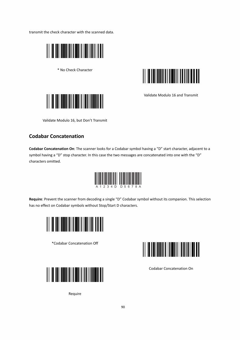
90
transmit the check character with the scanned data.
* No Check Character
Validate Modulo 16 and Transmit
Validate Modulo 16, but Don’t Transmit
Codabar Concatenation
Codabar Concatenation On: The scanner looks for a Codabar symbol having a “D” start character, adjacent to a
symbol having a “D” stop character. In this case the two messages are concatenated into one with the “D”
characters omitted.
Require: Prevent the scanner from decoding a single “D” Codabar symbol without its companion. This selection
has no effect on Codabar symbols without Stop/Start D characters.
*Codabar Concatenation Off
Codabar Concatenation On
Require
91
Codabar Message Length
To change the message length of Codabar, you can scan the bar codes below. Minimum and Maximum lengths =
2-60.
Minimum Default = 4, Maximum Default = 60.
Minimum Message Length
Maximum Message Length
MSI
Default All MSI Settings
To default all MSI Settings, scan the bar code below.
Default all MSI Settings
Enable/Disable MSI
To enable or disable MSI, scan the appropriate bar code below.
Default =MSI Off.

92
* MSI Off
MSI On
MSI Check Character
Different types of check characters are used with MSI bar codes. Default = Validate Type 10, but Don’t Transmit.
Validate Type 10/11 and Transmit: The scanner will only read MSI bar codes printed with the specified type check
character(s), and will transmit the character(s) at the end of the scanned data.
Validate Type 10/11, but Don’t Transmit: The unit will only read MSI bar codes printed with the specified type
check character(s), but will not transmit the check character(s) with the scanned data.
* Validate Type 10, but Don’t Transmit
Validate Type 10 and Transmit
Validate 2 Type 10 Characters, but Don’t Transmit
Validate 2 Type 10 Characters
and Transmit
Validate Type 11 then Type 10 Character, but Don’t
93
Transmit
Validate Type 11 then Type 10 Character and Transmit
Disable MSI Check Characters
MSI Message Length
To change the message length of MSI, you can scan the bar codes below. Minimum and Maximum lengths = 4-48.
Minimum Default = 4, Maximum Default = 48.
Minimum Message Length
Maximum Message Length
Matrix 2 of 5
Default All Matrix 2 of 5 Settings
To default all Matrix 2 of 5 Settings, scan the Bar code.
Default all Matrix 2 of 5 Settings

94
Enable/Disable Matrix 2 of 5
To enable or disable Matrix 2 of 5, scan the appropriate bar code below.
Default =Matrix 2 of 5 Off.
*Matrix 2 of 5 Off
Matrix 2 of 5 On
Matrix 2 of 5 Message Length
To change the message length of Matrix 2 of 5, you can scan the bar codes below. Minimum and Maximum lengths
= 1-80.
Minimum Default = 4, Maximum Default = 80.
Minimum Message Length
Maximum Message Length
GS1 DataBar
GS1 DataBar Omnidirectional
Default All GS1 DataBar Omnidirectional Settings
To default all GS1 DataBar Omnidirectional Settings, scan the bar code below.

95
Default all GS1 DataBar Omnidirectional Settings
Enable/Disable GS1 DataBar Omnidirectional
To enable or disable GS1 DataBar Omnidirectional, scan the appropriate bar code below.
Default =GS1 DataBar Omnidirectional On.
GS1 DataBar Omnidirectional Off
*GS1 DataBar Omnidirectional On
GS1 DataBar Limited
Default All GS1 DataBar Limited Settings
To default all GS1 DataBar Limited Settings, scan the bar code below.
Default all GS1 DataBar Limited Settings
Enable/Disable GS1 DataBar Limited
To enable or disable GS1 DataBar Limited, scan the appropriate bar code below.
Default =GS1 DataBar Limited On.

96
GS1 DataBar Limited Off
*GS1 DataBar Limited On
GS1 DataBar Expanded
Default All GS1 DataBar Expanded Settings
To default all GS1 DataBar Expanded Settings, scan the bar code below.
Default All GS1 DataBar Expanded Settings
Enable/Disable GS1 DataBar Expanded
To enable or disable GS1 DataBar Expanded, scan the appropriate bar code below.
Default =GS1 DataBar Expanded On.
GS1 DataBar Expanded Off
*GS1 DataBar Expanded On
GS1 DataBar Expanded Message Length
To change the message length of GS1 DataBar Expanded, you can scan the bar codes below. Minimum and
Maximum lengths = 4-74.
Minimum Default = 4, Maximum Default = 74.

97
Minimum Message Length
Maximum Message Length
GS1 Composite Codes
GS1 Composite symbology: A new class combined linear codes with a unique 2D composite component. GS1
Composite symbologies allow for the co-existence of symbologies already in use.
Default = GS1 Composite Codes Off.
* GS1 Composite Codes Off
GS1 Composite Codes On
UPC/EAN Version
UPC/EAN Version On: Decode GS1 Composite symbols that have a U.P.C. or an EAN linear component. (This does
not affect GS1 Composite symbols with a GS1-128 or GS1 linear component.)
Default = UPC/EAN Version Off.
* UPC/EAN Version Off
UPC/EAN Version On
Note: If you scan coupons that have both UPC and GS1 DataBar codes, you may wish to scan and output only the
data from the GS1 DataBar code. See Coupon GS1 DataBar Output for further information.

98
GS1 Composite Code Message Length
To change the message length of GS1 Composite Code, you can scan the bar codes below. Mini-mum and
Maximum lengths = 1-2435.
Minimum Default = 1, Maximum Default = 2435.
Minimum Message Length
Maximum Message Length
GS1 Emulation
The scanner can automatically format the output from any GS1 data carrier to emulate what would be encoded in
an equivalent GS1-128 or GS1 DataBar symbol. GS1 data carriers include UPC-A and UPC-E, EAN-13 and EAN-8,
ITF-14, GS1-128, and GS1-128 DataBar and GS1 Composites. (Any application that accepts GS1 data can be
simplified since it only needs to recognize one data carrier type.)
GS1-128 Emulation: All retail codes (U.P.C., UPC-E, EAN8, EAN13) are expanded out to 16 digits. If the AIM ID is
enabled, the value will be the GS1-128 AIM ID, ] C1 .
GS1 DataBar Emulation: All retail codes (U.P.C., UPC-E, EAN8, EAN13) are expanded out to 16 digits. If the AIM ID
is enabled, the value will be the GS1-DataBar AIM ID, ] em .
GS1 Code Expansion Off: Retail code expansion is disabled, and UPC-E expansion is controlled by the UPC-E0
Expand setting. If the AIM ID is enabled, the value will be the GS1-128 AIM ID, ] C1.
EAN8 to EAN13 Conversion: All EAN8 bar codes are converted to EAN13 format.
Default = GS1 Emulation Off.
* GS1 Emulation Off
99
GS1 DataBar Emulation
GS1-128 Emulation
EAN8 to EAN13 Conversion
GS1 Code Expansion Off
TCIF Linked Code 39 (TLC39)
To enable or disable Composite bar codes of TLC39, you can scan the bar codes below.
Default =TCIF Linked Code 39 Off.
NOTE: The MicroPDF417 component can only be decoded if TLC39 is on. The linear component may be decoded as
Code 39 even if TLC39 is off.
* TCIF Linked Code 39 Off
TCIF Linked Code 39 On
PDF417
Default All PDF417 Settings
To default all PDF417 Settings, scan the bar code below.
100
Default all PDF417 Settings
Enable/Disable PDF417
To enable or disable PDF417, scan the appropriate bar code below.
Default =PDF417 On.
PDF417 Off
* PDF417 On
PDF417 Message Length
To change the message length of PDF417, you can scan the bar codes below. Mini-mum and Maximum lengths =
1-2750.
Minimum Default = 1, Maximum Default = 2750.
Minimum Message Length
Maximum Message Length
Enable/Disable MacroPDF417
MacroPDF417 is an implementation of PDF417 capable of encoding very large amounts of data into multiple

101
PDF417 bar codes.
MacroPDF417 On: These multiple bar codes are assembled into a single data string.
Default = MacroPDF417 On.
To enable or disable MacroPDF417, scan the appropriate bar code below.
MacroPDF417 Off
* MacroPDF417 On
Default All MicroPDF417 Settings
To default all MicroPDF417 Settings, scan the bar code below.
Default all MicroPDF417 Settings
Enable/Disable MicroPDF417
To enable or disable MicroPDF417, scan the appropriate bar code below.
Default =MicroPDF417 Off.
* MicroPDF417 Off
MicroPDF417 On

102
MicroPDF417 Message Length
To change the message length of MicroPDF417, you can scan the bar codes below. Minimum and Maximum
lengths = 1-366.
Minimum Default = 1, Maximum Default = 366.
Minimum Message Length
Maximum Message Length
Data Matrix
Default All Data Matrix Settings
To default all Data Matrix Settings, scan the bar code below.
Default All Data Matrix Settings
Enable/Disable Data Matrix
To enable or disable Data Matrix, scan the appropriate bar code below.
Default =Data Matrix On.
103
Data Matrix Off
*Data Matrix On
Data Matrix Message Length
To change the message length of Data Matrix, you can scan the bar codes below. Minimum and Maximum lengths
= 1-3116.
Minimum Default = 1, Maximum Default = 3116.
Minimum Message Length
Maximum Message Length
Maxicode
Default All MaxiCode Settings
To default all Maxicode Settings, scan the bar code below.
Default all Maxicode Settings
Enable/Disable MaxiCode
To enable or disable Maxicode, scan the appropriate bar code below.
Default =MaxiCode Off.

104
* MaxiCode Off
MaxiCode On
MaxiCode Message Length
To change the message length of MaxiCode, you can scan the bar codes below. Minimum and Maximum lengths =
1-150.
Minimum Default = 1, Maximum Default = 150.
Minimum Message Length
Maximum Message Length
QR Code
Default All QR Code Settings
To default all QR Code Settings, scan the bar code below.
Default all QR Code Settings

105
Enable/Disable QR Code
To enable or disable QR Code, scan the appropriate bar code below.
Notes: This selection below applies to both QR Code and Micro QR Code.
Default =QR Code On.
QR Code Off
*QR Code On
QR Code Message Length
To change the message length of QR Code, you can scan the bar codes below. Minimum and Maximum lengths =
1-7089.
Minimum Default = 1, Maximum Default = 7089.
Minimum Message Length
Maximum Message Length
Aztec Code
Default All Aztec Settings
To default all Aztec Settings, scan the bar code below.

106
Default All Aztec Settings
Enable/Disable Aztec
To enable or disable Aztec, scan the appropriate bar code below.
Default =Aztec On.
Aztec Off
*Aztec On
Aztec Code Message Length
To change the message length of Aztec Code, you can scan the bar codes below. Minimum and Maximum lengths =
1-3832.
Minimum Default = 1, Maximum Default = 3832.
Minimum Message Length
Maximum Message Length
Aztec Append
This function allows the scanner to append the data from several Aztec bar codes together before transmitting

107
them to the host computer. When the scanner encounters an Aztec bar code with the append trigger character(s),
it buffers the number of Aztec bar codes determined by information encoded in those bar codes. Once the proper
number of codes is reached, the data is output in the order specified in the bar codes.
Default =Aztec Append Off.
*Aztec Append Off
Aztec Append On
Aztec Code Page
Aztec Code pages define the mapping of character codes to characters. If the data received does not display with
the proper characters, it may be because the bar code being scanned was created using a code page that is
different from the one the host program is expecting. If this is the case, scan the bar code below, select the code
page with which the bar codes were created, and scan the value and the Save bar code from the APPENDIX B
Programming Number. The data characters should then appear properly.
Aztec Code Page
Chinese Sensible (Han Xin) Code
Default All Chinese Sensible (Han Xin) Code Settings
To default all Chinese Sensible (Han Xin) Code Settings, scan the bar code below.
Default all Chinese Sensible (Han Xin) Code Settings

108
Enable/Disable Chinese Sensible (Han Xin) Code
To enable or disable Chinese Sensible (Han Xin) Code, scan the appropriate bar code below.
Default =Chinese Sensible (Han Xin) Code Off.
*Chinese Sensible (Han Xin) Code Off
Chinese Sensible (Han Xin) Code On
Han Xin Code Message Length
To change the message length of Han Xin Code, you can scan the bar codes below. Minimum and Maximum
lengths = 1-7833.
Minimum Default = 1, Maximum Default = 7833.
Minimum Message Length
Maximum Message Length
Postal Codes – Linear
The following lists linear postal codes. Any combination of linear postal code selections can be active at a time.
China Post (Hong Kong 2 of 5)
Default All China Post Settings
To default all China Post Settings, scan the bar code below.

109
Default All China Post Settings
Enable/Disable China Post
To enable or disable China Post, scan the appropriate bar code below.
Default =China Post Off.
*China Post Off
China Post On
China Post (Hong Kong 2 of 5) Message Length
To change the message length of China Post (Hong Kong 2 of 5), you can scan the bar codes below. Minimum and
Maximum lengths = 2-80.
Minimum Default = 4, Maximum Default = 80.
Minimum Message Length
Maximum Message Length
Korea Post
Default All Korea Post Settings
To default all Korea Post Settings, scan the bar code below.

110
Default All Korea Post Settings
Enable/Disable Korea Post
To enable or disable Korea Post, scan the appropriate bar code below.
Default =Korea Post Off.
*Korea Post Off
Korea Post On
Korea Post Message Length
To change the message length of Korea Post, you can scan the bar codes below. Minimum and Maximum lengths =
2-80.
Minimum Default = 4, Maximum Default = 48.
Minimum Message Length
Maximum Message Length
Korea Post Check Digit
The check digit is the last character of the symbol used to verify the integrity of the data. Scan the appropriate bar
code below to transmit the bar code data with or without the Korea Post check digit. It is always verified to
guarantee the integrity of the data.

111
Default = Don’t Transmit Check Digit.
* Don’t Transmit Check Digit
Transmit Check Digit
Postal Codes - 2D
The following lists the possible 2D postal codes, and 2D postal code combinations that are allowed. Only one 2D
postal code selection can be active at a time. If you scan a second 2D postal code selection, the first selection is
overwritten.
Default = 2D Postal Codes Off.
* 2D Postal Codes Off
Single 2D Postal Codes
Australian Post On
British Post On
Canadian Post On
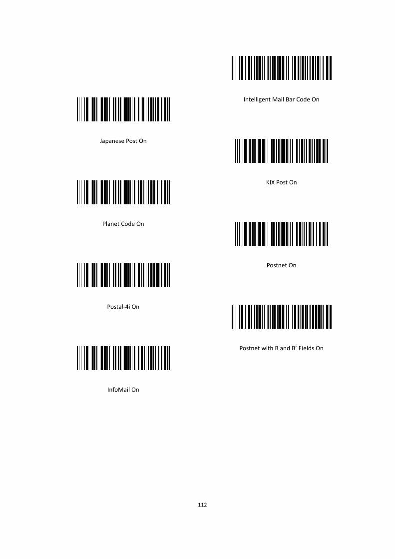
112
Intelligent Mail Bar Code On
Japanese Post On
KIX Post On
Planet Code On
Postnet On
Postal-4i On
Postnet with B and B’ Fields On
InfoMail On
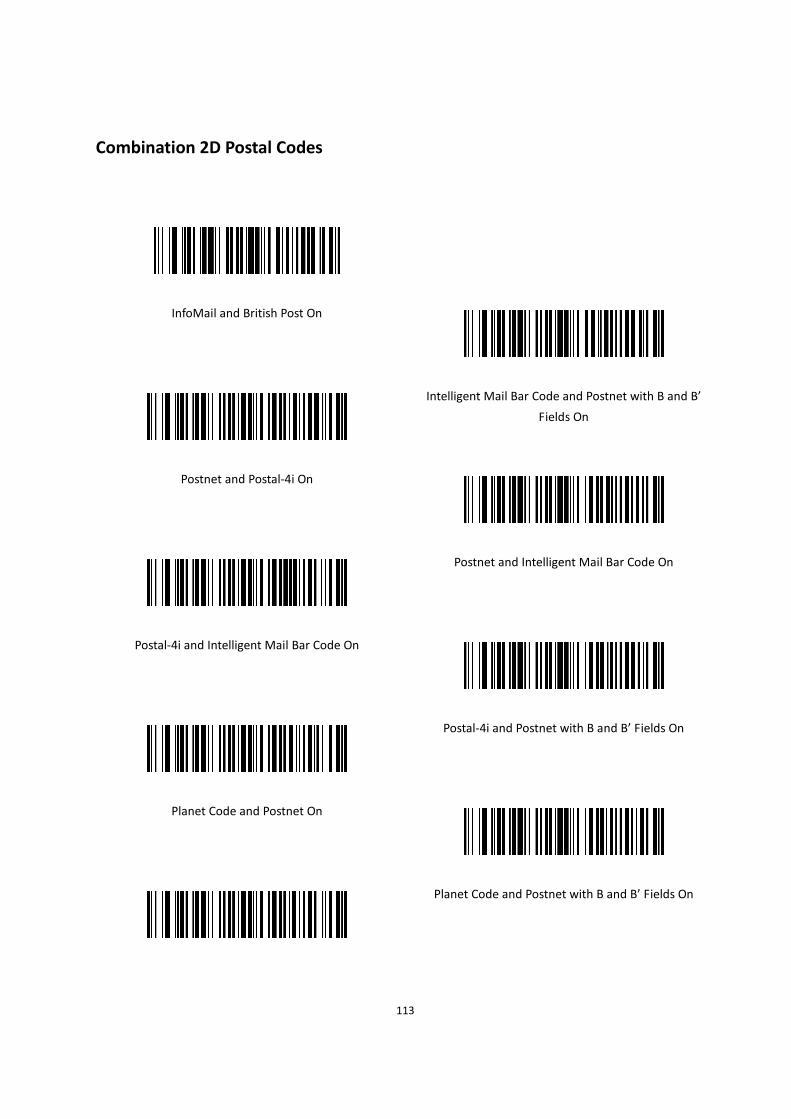
113
Combination 2D Postal Codes
InfoMail and British Post On
Intelligent Mail Bar Code and Postnet with B and B’
Fields On
Postnet and Postal-4i On
Postnet and Intelligent Mail Bar Code On
Postal-4i and Intelligent Mail Bar Code On
Postal-4i and Postnet with B and B’ Fields On
Planet Code and Postnet On
Planet Code and Postnet with B and B’ Fields On
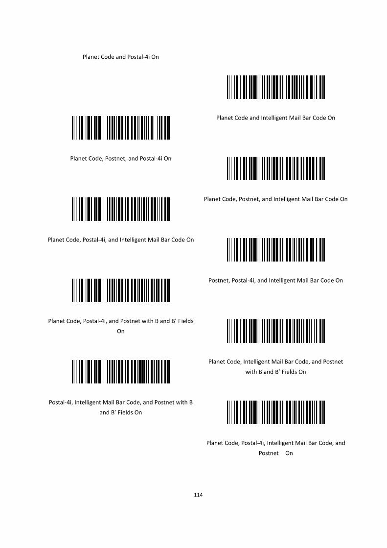
114
Planet Code and Postal-4i On
Planet Code and Intelligent Mail Bar Code On
Planet Code, Postnet, and Postal-4i On
Planet Code, Postnet, and Intelligent Mail Bar Code On
Planet Code, Postal-4i, and Intelligent Mail Bar Code On
Postnet, Postal-4i, and Intelligent Mail Bar Code On
Planet Code, Postal-4i, and Postnet with B and B’ Fields
On
Planet Code, Intelligent Mail Bar Code, and Postnet
with B and B’ Fields On
Postal-4i, Intelligent Mail Bar Code, and Postnet with B
and B’ Fields On
Planet Code, Postal-4i, Intelligent Mail Bar Code, and
Postnet On

115
Planet Code, Postal-4i, Intelligent Mail Bar Code, and
Postnet with B and B’ Fields On
Planet Code Check Digit
The check digit is the last character of the symbol used to verify the integrity of the data. Scan the appropriate bar
code below to transmit the bar code data with or without the Planet Code check digit. It is always verified to
guarantee the integrity of the data.
Default = Don’t Transmit Check Digit .
* Don’t Transmit Check Digit
Transmit Check Digit
Postnet Check Digit
The check digit is the last character of the symbol used to verify the integrity of the data. Scan the appropriate bar
code below to transmit the bar code data with or without the Postnet check digit. It is always verified to guarantee
the integrity of the data.
Default = Don’t Transmit Check Digit.
* Don’t Transmit Check Digit
Transmit Check Digit

116
Australian Post Interpretation
This option controls what interpretation is applied to customer fields in Australian 4-State symbols.
Bar Output: It lists the bar patterns in “0123” format.
Numeric N Table: It causes that field to be interpreted as numeric data using the N Table.
Alphanumeric C Table: It causes the field to be interpreted as alphanumeric data using the C Table. Refer to the
Australian Post Specification Tables.
Combination C and N Tables: It causes the field to be interpreted using either the C or N Tables.
Default =Bar Output.
* Bar Output
Numeric N Table
Alphanumeric C Table
Combination C and N Tables

117
CHAPTER 8 PREFIX AND SUFFIX
When a bar code is scanned, additional information is sent to the host computer along with the bar code data. This
group of bar code data and additional, user-defined data is called a “message string.” The selections in this section
are used to build the user-defined data into the message string. Prefix and Suffix characters are data characters
that can be sent before and after scanned data. You can specify if they should be sent with all symbologies, or only
with specific symbologies. The following illustration shows the breakdown of a message string:
Prefix Scanned Data Suffix
• The selections in this chapter are only used if you wish to alter the default settings.
Default prefix = None. Default suffix = None.
• A prefix or suffix may be added or cleared from one symbology or all symbologies.
• You can add any prefix or suffix from the APPENDIX D ASCII Conversion Chart.
• You can string together several entries for several symbologies at one time.
• Enter prefixes and suffixes in the order in which you want them to appear on the output.
• When setting up for specific symbologies (as opposed to all symbologies), the specific symbology ID value counts
as an added prefix or suffix character.
• The maximum size of a prefix or suffix configuration is 200 characters, which includes header information.
Add a Prefix or Suffix:
1. Scan the Add Prefix or Add Suffix symbol .
2. Determine the 2 digit Hex value from the Symbology Chart (included in the APPENDIX C Symbology
Charts - AIM ID) for the symbology to which you want to apply the prefix or suffix. For example, for Code
128, Hex ID is “6A”.
3. Scan the 2 hex digits from the APPENDIX B Programming Number inside the back cover of this manual or
scan 9, 9 for all symbologies.
4. Determine the hex value from the APPENDIX D ASCII Conversion Chart, for the prefix or suffix you wish to
enter.
5. Scan the 2 digit hex value from the APPENDIX B Programming Number inside the back cover of this
manual.
6. Repeat Steps 4 and 5 for every prefix or suffix character.
7. To add AIM I.D., scan 5, C, 8, 1.
To add a backslash (\), scan 5, C, 5, C.
Note: To add a backslash (\) as in Step 7, you must scan 5C twice – once to create the leading backslash

118
and then to create the backslash itself.
8. Scan Save to exit and save, or scan Discard to exit without saving. Repeat Steps 1-6 to add a prefix or
suffix for another symbology.
Example: Add a Suffix to a specific symbology
To send a CR (carriage return)Suffix for U.P.C. only:
1. Scan Add Suffix.
2. Determine the 2 digit hex value from the Symbology Chart (included in the APPENDIX C Symbology
Charts - AIM ID)for U.P.C..
3. Scan 6, 3 from the APPENDIX B Programming Number inside the back cover of this manual.
4. Determine the hex value from the APPENDIX D ASCII Conversion Chart, for the CR (carriage return).
5. Scan 0, D from the APPENDIX B Programming Number inside the back cover of this manual.
6. Scan Save, or scan Discard to exit without saving.
Clear One or All Prefixes or Suffixes
You can clear a single prefix or suffix, or clear all prefixes/suffixes for a symbology. If you have been entering
prefixes and suffixes for single symbologies, you can use Clear One Prefix (Suffix) to delete a specific character
from a symbology. When you Clear All Prefixes (Suffixes), all the prefixes or suffixes for a symbology are deleted.
1. Scan the Clear One Prefix or Clear One Suffix symbol.
2. Determine the 2 digit Hex value from the Symbology Chart (included in the APPENDIX C Symbology
Charts - AIM ID) for the symbology from which you want to clear the prefix or suffix.
3. Scan the 2 digit hex value from the APPENDIX B Programming Number inside the back cover of this
manual or scan 9, 9 for all symbologies. Your change is automatically saved.
Add a Carriage Return Suffix to All Symbologies
Scan the following bar code if you wish to add a carriage return suffix to all symbologies at once. This action first
clears all current suffixes, then programs a carriage return suffix for all symbologies.
Add CR Suffix All Symbologies

119
Prefix Selections
Add Prefix
Clear One Prefix
Clear All Prefixes
Suffix Selections
Add Suffix
Clear One Suffix
Clear All Suffixes
Function Code Transmit
When this selection is enabled and function codes are contained within the scanned data, the scanner transmits
the function code to the terminal. Charts of these function codes are provided in Supported Interface Keys starting
on APPENDIX A Interface Keys. When the scanner is in keyboard wedge mode, the scan code is converted to a key
code before it is transmitted.
Default = Enable.

120
*Enable Function Code Transmit
Disable Function Code Transmit
Intercharacter, Interfunction, and Intermessage Delays
Some terminals drop information (characters) if data comes through too quickly. Intercharacter, interfunction, and
intermessage delays slow the transmission of data, increasing data integrity.
Intercharacter Delay
An intercharacter delay of up to 5000 milliseconds (in 5ms increments) may be placed between the transmission of
each character of scanned data. Scan the Intercharacter Delay bar code below, then scan the number of 5ms
delays, and the Save bar code using the APPENDIX B Programming Number inside the back cover of this manual.
Intercharacter Delay
To remove this delay, scan the Intercharacter Delay bar code, then set the number of delays to 0. Scan the Save
bar code using the APPENDIX B Programming Number inside the back cover of this manual.
Note: Intercharacter delays are not supported in USB serial emulation.
Interfunction Delay
An interfunction delay of up to 5000 milliseconds (in 5ms increments) may be placed between the transmission of
each segment of the message string. Scan the Interfunction Delay bar code below, then scan the number of 5ms
delays, and the Save bar code using the Programming Chart inside the back cover of this manual.

121
Interfunction Delay
To remove this delay, scan the Interfunction Delay bar code, then set the number of delays to 0. Scan the Save bar
code using the APPENDIX B Programming Number inside the back cover of this manual.
Intermessage Delay
An intermessage delay of up to 5000 milliseconds (in 5ms increments) may be placed between each scan
transmission. Scan the Intermessage Delay bar code below, then scan the number of 5ms delays, and the Save
bar code using the APPENDIX B Programming Number inside the back cover of this manual.
Intermessage Delay
To remove this delay, scan the Intermessage Delay bar code, then set thenumber of delays to 0. Scan the Save bar
code using the APPENDIX B Programming Number inside the back cover of this manual.

122
CHAPTER 9 SERIAL PROGRAMMING COMMANDS
The serial programming commands can be used in place of the programming bar codes. Both the serial commands
and the programming bar codes will program the scanner. For complete descriptions and examples of each serial
programming command, refer to the corresponding programming bar code in this manual.
The device must be set to an RS232 interface . The following commands can be sent via a PC COM port using
terminal emulation software.
Function Commands
The serial function commands have the following formation:
STX + CMD(see table 11-1) + EXT
Table 9-1 Function Commands
Function Command Formation
Beeper Bell \x07 \x02\x07\x03
Trigger T \x02T\x03
Untrigger U \x02U\x03
Menu Commands
The menu commands have the following syntax:
Header + Group + Item + .
Header consists of three characters. The details refer to Table 9-2 .
Table 9-2 Header
Command Function
First Character(Menu type) M Normal type menu
R Store in RAM
N Store in ROM
Second Character(Storage type)
C Store in customer setting place
S Setting Third Character(Action)
Q Query the current setting

123
R Return the valid setting range
Note: As the default action is setting and default storage is in ROM, the 'MNS' can be simplified to be 'M'.
The serial menu commands which sets the DB50 have the following formation:
STX + @ + MENU(see table 11-2) + EXT
For example:
• Set the DB50 default: \x02@M0401.\x03
• Query the current interface: \x02@MRQ0201.\x03
• Query the range value of reread delay : \x02@MRR1102.\x03
Resetting the Custom Defaults
If you want the custom default settings restored to your scanner, scan the Activate Custom Defaults bar code
below. This resets the scanner to the custom default settings. If there are no custom defaults, it will reset the
scanner to the factory default settings. Any settings that have not been specified through the custom defaults will
be defaulted to the factory default settings.
Activate Custom Defaults
The charts on the following pages list the factory default settings for each of the commands (indicated by an
asterisk (*) on the programming pages).
DB50 Menu Commands
Resetting the Factory
Defaults Activate Defaults M0401.
RS232 Serial Port M0501.
USB Keyboard (PC) M0502.
USB Keyboard (Mac) M0503.
USB Japanese Keyboard (PC) M0201_134.
Interfaces
USB Serial M0201_130.

124
CTS/RTS Emulation Off M0701_0.
CTS/RTS Emulation On M0701_1.
ACK/NAK Mode Off M0702_0. USB
ACK/NAK Mode On M0702_1.
U.S.A. M0801_0.
Albania M0801_35.
Azeri (Cyrillic) M0801_81.
Azeri (Latin) M0801_80.
Belarus M0801_82.
Belgium M0801_1.
Bosnia M0801_33.
Brazil M0801_16.
Brazil (MS) M0801_59.
Bulgaria (Cyrillic) M0801_52.
Bulgaria (Latin) M0801_53.
Canada (French legacy) M0801_54.
Canada (French) M0801_18.
Canada (Multilingual) M0801_55.
Croatia M0801_32.
Czech M0801_15.
Czech (Programmers) M0801_40
Czech (QWERTY) M0801_39.
Czech (QWERTZ) M0801_38.
Denmark M0801_8.
Dutch (Netherlands) M0801_11.
Estonia M0801_41.
Faeroese M0801_83.
Keyboard Country
Finland M0801_2.

125
France M0801_3.
Gaelic M0801_84.
Germany M0801_4.
Greek M0801_17.
Greek (220 Latin) M0801_64.
Greek (220) M0801_61.
Greek (319 Latin) M0801_65.
Greek (319) M0801_62.
Greek (Latin) M0801_63.
Greek (MS) M0801_66.
Greek (Polytonic) M0801_60.
Hebrew M0801_12.
Hungarian (101 key) M0801_50.
Hungary M0801_19.
Iceland M0801_75.
Irish M0801_73.
Italian (142) M0801_56.
Italy M0801_5.
Japan ASCII M0801_28.
Kazakh M0801_78.
Kyrgyz (Cyrillic) M0801_79.
Latin America M0801_14.
Latvia M0801_42.
Latvia (QWERTY) M0801_43.
Lithuania M0801_44.
Lithuania (IBM) M0801_45.
Macedonia M0801_34.
Malta M0801_74.

126
Mongolian (Cyrillic) M0801_86.
Norway M0801_9.
Poland M0801_20.
Polish (214) M0801_57.
Polish (Programmers) M0801_58.
Portugal M0801_13.
Romania M0801_25.
Russia M0801_26.
Russian (MS) M0801_67.
Russian (Typewriter) M0801_68.
SCS M0801_21.
Serbia (Cyrillic) M0801_37.
Serbia (Latin) M0801_36.
Slovakia M0801_22.
Slovakia (QWERTY) M0801_49.
Slovakia (QWERTZ) M0801_48.
Slovenia M0801_31.
Spain M0801_10.
Spanish variation M0801_51.
Sweden M0801_23.
Switzerland (French) M0801_29.
Switzerland (German) M0801_6.
Tatar M0801_85.
Turkey F M0801_27.
Turkey Q M0801_24.
Ukrainian M0801_76.
United Kingdom M0801_7.
United States (Dvorak right) M0801_89.

127
United States (Dvorak left) M0801_88
United States (Dvorak) M0801_87.
United States (International) M0801_30.
Uzbek (Cyrillic) M0801_77.
Regular M0802_0.
Caps Lock M0802_1.
Shift Lock M0802_2.
Automatic Caps Lock M0802_6.
Emulate External Keyboard M0802_5.
Keyboard Style
Autocaps via NumLock M0802_7.
Keyboard Conversion Off M0803_0.
Convert all Characters to Upper Case M0803_1. Keyboard Conversion
Convert all Characters to Lower Case M0803_3.
Control Character Output Off M0804_0. Keyboard Control
Character Output Control Character Output On M0804_1.
Control + ASCII Off M0805_0.
DOS Mode Control+ ASCII M0805_1.
Windows Mode Control + ASCII M0805_2.
Windows Mode Prefix/Suffix Off M0805_3.
Turbo Mode Off M0806_0.
Turbo Mode On M0806_1.
Numeric Keypad Off M0807_0.
Keyboard Modifiers
Numeric Keypad On M0807_1.
300 BPS M0901_0.
600 BPS M0901_1.
1200 BPS M0901_2.
2400 BPS M0901_3.
RS232 Baud Rate
4800 BPS M0901_4.

128
9600 BPS M0901_5.
19200 BPS M0901_6.
38400 BPS M0901_7.
57600 BPS M0901_8.
115200 BPS M0901_9.
RS232 Receiver TimeOut RS232 receiver time-out M0903.
Power Up Beeper Off M1001_0. Suppress Power-up
Beeps Power Up Beeper On M1001_1.
Beep on BEL Off M1002_0. Beeper on BEL
Beep on BEL On M1002_1.
Trigger Click Off M1003_0. Trigger Click
Trigger Click On M1003_1.
Beeper-Good Read Off M1004_0. Beeper – Good Read
Beeper-Good Read On M1004_1.
Off M1005_0.
Low Volume M1005_1.
Medium Volume M1005_2.
Beeper Volume-Good
Read
High Volume M1005_3.
Low Frequency(800 Hz) M1006_800.
Medium Frequency (1600 Hz) M1006_1600. Beeper Tone-Good Read
High Frequency (3200 Hz) M1006_3200.
Beeper Tone- User
Specified Setting User specified setting of beeper tone M1006.
Razz(250 Hz) M1007_250.
Medium(3250 Hz) M1007_3250. Beeper Pitch – Error
High(4200 Hz) M1007_4200.
Beeper Duration-Good
Normal Beep M1008_0.

129
Read Short Beep M1008_1.
LED-Good Read Off M1009_0. LED – Good Read
LED-Good Read On M1009_1.
1 Good Read Beep/LED Flash M1010_1.
2 Good Read Beeps/LED Flashes M1010_2.
Number of Good
Decode Beeps- Good
Read 3 Good Read Beeps/LED Flashes M1010_3.
Number of Beeps – Error Number of Error Beeps/LED Flashes M1011.
No Delay M1101_0.
Short Delay(500 ms) M1101_500.
Medium Delay(1000 ms) M1101_1000. Good Read Delay
Long Delay(1500 ms) M1101_1500.
No Delay M1102_0.
Short (500 ms) M1102_500.
Medium (1000 ms) M1102_1000. Reread Delay
Extra Long (2000 ms) M1102_2000.
User-Specified Reread
Delay User-Specified Reread Delay M1102.
Intercharacter Delay Intercharacter Delay M1103.
Delay Length M1104. User Specified
Intercharacter Delay Character to Trigger Delay M1105.
Interfunction Delay Interfunction Delay M1106.
Intermessage Delay Intermessage Delay M1107.
Low M1201_50. LED Illumination -
Manual Trigger High M1201_80.
Low M1202_50. Idle Illumination -
Presentation Mode High M1202_80.

130
Manual Trigger Mode Manual Trigger - Normal M1301.
Presentation Mode Presentation Mode M1302.
Hand Held Scanning - Mobile Phone M1303. Mobile Phone/Display
Mode Presentation Scanning - Mobile Phone M1304.
Presentation Sensitivity High Sensitivity M1402.
Hands Free Time-Out Hands Free Time-Out M1403.
Presentation Centering Off M1501_0.
Presentation Centering On M1501_1.
Top of Presentation Centering Window M1502.
Bottom of Presentation Centering
Window M1503.
Left of Presentation Centering Window M1504.
Presentation Centering
Right of Presentation Centering Window M1505.
Manual Trigger Centering Off M1701_0.
Manual Trigger Centering On M1701_1.
Top of Manual Trigger Centering Window M1702.
Bottom of Manual Trigger Centering
Window M1703.
Left of Manual Trigger Centering Window M1704.
Manual Trigger
Centering
Right of Manual Trigger Centering
Window M1705.
Video Reverse Off M1603_0.
Video Reverse Only M1603_1. Video Reverse
Video Reverse and Standard Bar Codes M1603_2.
Upright M1604_0. Working Orientation
Vertical, Bottom to Top M1604_1.

131
Upside Down M1604_2.
Vertical, Top to Bottom M1604_3.
Enable M1605_0. Function Code Transmit
Disable M1605_1.
To Add a Carriage
Return Suffix to All
Symbologies
Add CR Suffix All Symbologies M1801.
Add Prefix M1802.
Clear One Prefix M1803. Prefix
Clear All Prefixes M1804.
Add Suffix M1805.
Clear One Suffix M1806. Suffix
Clear All Suffixes M1807.
Default Data Format M1901.
Enter Data Format M1903.
Clear One Data Format M1904. Data Format Editor
Clear All Data Formats M1905.
Data Formatter Off M1902_0.
Data Formatter On, Not Required, Keep
Prefix/Suffix M1902_1. Data Formatter
Data Format Required, Keep Prefix/Suffix M1902_2.
Primary Data Format M1906_0.
Data Format 1 M1906_1.
Data Format 2 M1906_2.
Primary/Alternate Data
Formats
Data Format 3 M1906_3.
Show Software Revision Show Revision M2003.
Aim Mode Off M2101_0. Aim Mode
Aim Mode On M2101_3.

132
All Symbologies Off M3001_0. All Symbologies
All Symbologies On M3001_1.
Default All Codabar
Settings M3101.
Off M3102_0. Codabar
On M3102_1.
Don’t Transmit M3103_0. Codabar Start/Stop Char
Transmit M3103_1.
No Check Char. M3104_0.
Validate, But Don’t Transmit M3104_1. Codabar Check Char
Validate, and Transmit M3104_2.
Off M3105_0.
On M3105_1. Codabar Concatenation
Require M3105_2.
Minimum (2 - 60) M3106. Codabar Message
Length Maximum (2 - 60) M3107.
Default All Code 39 Settings M3201.
Off M3202_0. Code 39
On M3202_1.
Don’t Transmit M3203_0. Code 39 Start/Stop
Char Transmit M3203_1.
No Check Char. M3204_0.
Validate, But Don’t Transmit M3204_1. Code 39 Check Char
Validate, and Transmit M3204_2.
Minimum (0 - 48) M3205. Code 39 Message
Length Maximum (0 - 48) M3206.
Code 39 Append
Off M3207_0.
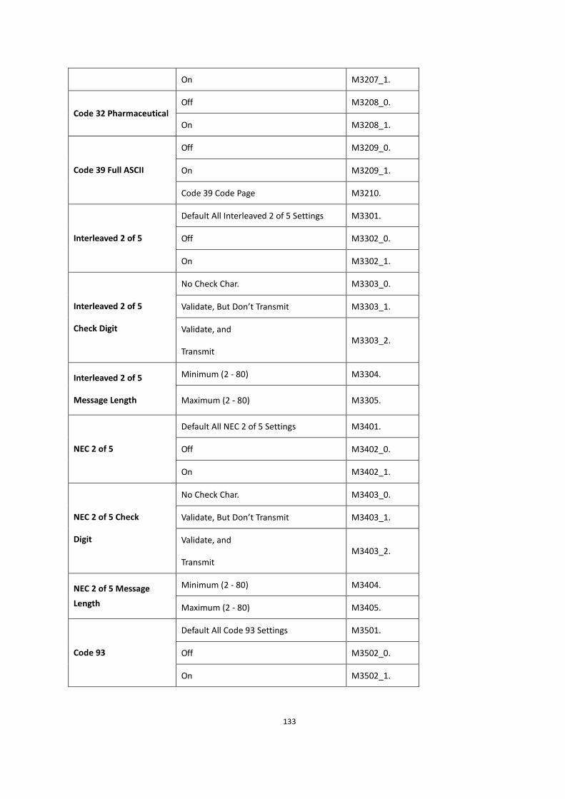
133
On M3207_1.
Off M3208_0. Code 32 Pharmaceutical
On M3208_1.
Off M3209_0.
On M3209_1. Code 39 Full ASCII
Code 39 Code Page M3210.
Default All Interleaved 2 of 5 Settings M3301.
Off M3302_0. Interleaved 2 of 5
On M3302_1.
No Check Char. M3303_0.
Validate, But Don’t Transmit M3303_1. Interleaved 2 of 5
Check Digit Validate, and
Transmit M3303_2.
Minimum (2 - 80) M3304. Interleaved 2 of 5
Message Length Maximum (2 - 80) M3305.
Default All NEC 2 of 5 Settings M3401.
Off M3402_0. NEC 2 of 5
On M3402_1.
No Check Char. M3403_0.
Validate, But Don’t Transmit M3403_1. NEC 2 of 5 Check
Digit Validate, and
Transmit M3403_2.
Minimum (2 - 80) M3404. NEC 2 of 5 Message
Length Maximum (2 - 80) M3405.
Default All Code 93 Settings M3501.
Off M3502_0. Code 93
On M3502_1.
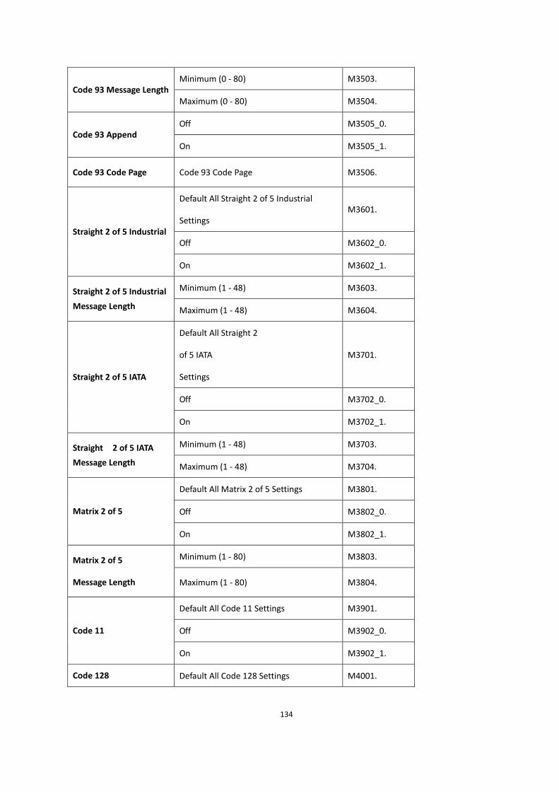
134
Minimum (0 - 80) M3503. Code 93 Message Length
Maximum (0 - 80) M3504.
Off M3505_0. Code 93 Append
On M3505_1.
Code 93 Code Page Code 93 Code Page M3506.
Default All Straight 2 of 5 Industrial
Settings M3601.
Off M3602_0. Straight 2 of 5 Industrial
On M3602_1.
Minimum (1 - 48) M3603. Straight 2 of 5 Industrial
Message Length Maximum (1 - 48) M3604.
Default All Straight 2
of 5 IATA
Settings
M3701.
Off M3702_0.
Straight 2 of 5 IATA
On M3702_1.
Minimum (1 - 48) M3703. Straight 2 of 5 IATA
Message Length Maximum (1 - 48) M3704.
Default All Matrix 2 of 5 Settings M3801.
Off M3802_0. Matrix 2 of 5
On M3802_1.
Minimum (1 - 80) M3803. Matrix 2 of 5
Message Length Maximum (1 - 80) M3804.
Default All Code 11 Settings M3901.
Off M3902_0. Code 11
On M3902_1.
Code 128 Default All Code 128 Settings M4001.

135
Off M4002_0.
On M4002_1.
Off M4003_0. ISBT Concatenation
On M4003_1.
Minimum (0 - 80) M4004. Code 128 Message
Length Maximum (0 - 80) M4005.
Off M4006_0. Code 128 Append
On M4006_1.
Code 128 Code Page
Code 128 Code
Page M4007.
Default All GS1-128
Settings M4101.
Off M4102_0. GS1-128
On M4102_1.
Minimum (1 - 80) M4103. GS1-128 Message
Length Maximum (0 - 80) M4104.
Default All Telepen Settings M4201.
Off M4202_0. Telepen
On M4202_1.
AIM Telepen Output M4203_0. Telepen Output
Original Telepen Output M4203_1.
Default All UPC-A Settings M4301.
Off M4302_0. UPC-A
On M4302_1.
Off M4303_0. UPC-A Check Digit
On M4303_1.
Off M4304_0. UPC-A Number System
On M4304_1.
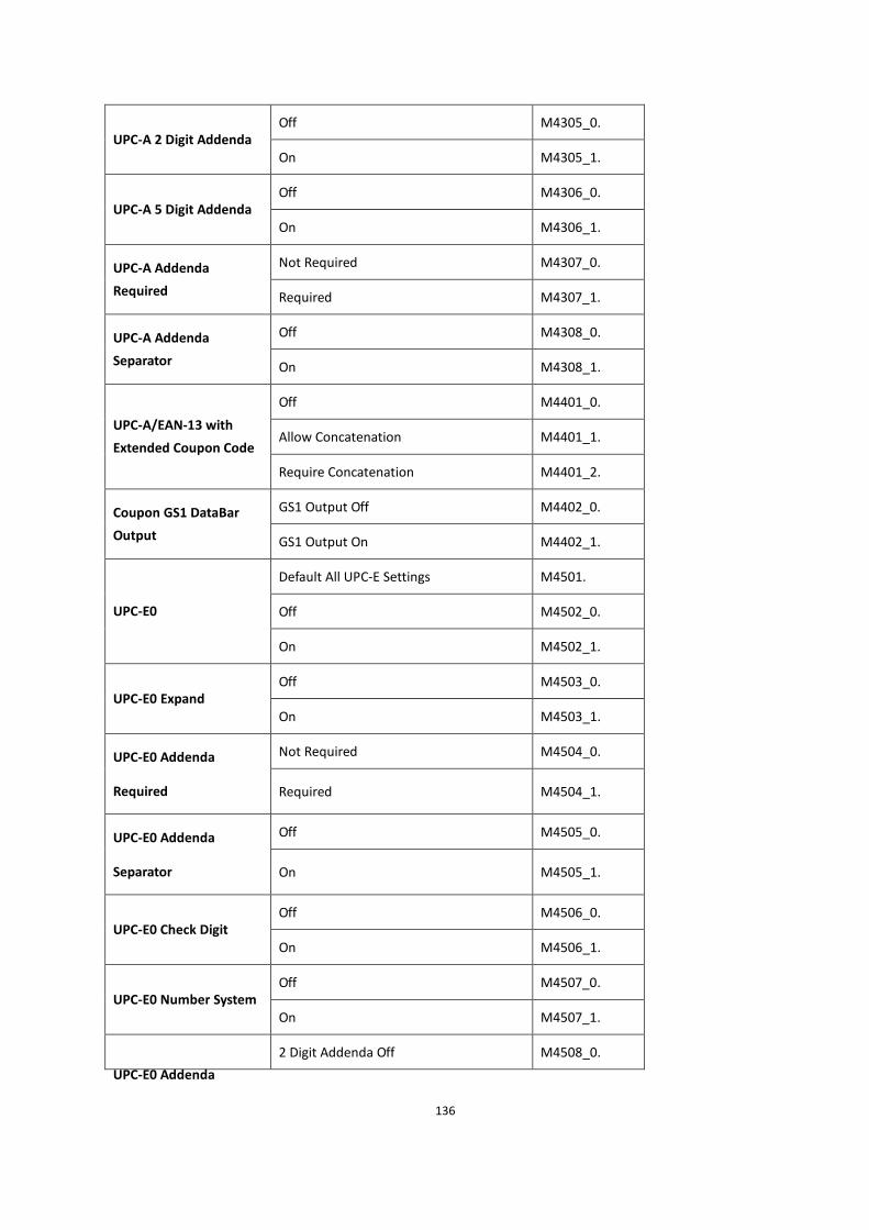
136
Off M4305_0. UPC-A 2 Digit Addenda
On M4305_1.
Off M4306_0. UPC-A 5 Digit Addenda
On M4306_1.
Not Required M4307_0. UPC-A Addenda
Required Required M4307_1.
Off M4308_0. UPC-A Addenda
Separator On M4308_1.
Off M4401_0.
Allow Concatenation M4401_1. UPC-A/EAN-13 with
Extended Coupon Code
Require Concatenation M4401_2.
GS1 Output Off M4402_0. Coupon GS1 DataBar
Output GS1 Output On M4402_1.
Default All UPC-E Settings M4501.
Off M4502_0. UPC-E0
On M4502_1.
Off M4503_0. UPC-E0 Expand
On M4503_1.
Not Required M4504_0. UPC-E0 Addenda
Required Required M4504_1.
Off M4505_0. UPC-E0 Addenda
Separator On M4505_1.
Off M4506_0. UPC-E0 Check Digit
On M4506_1.
Off M4507_0. UPC-E0 Number System
On M4507_1.
UPC-E0 Addenda
2 Digit Addenda Off M4508_0.

137
2 Digit Addenda On M4508_1.
5 Digit Addenda Off M4509_0.
5 Digit Addenda On M4509_1.
Off M4510_0. UPC-E1
On M4510_1.
Default All EAN/JAN Settings M4601.
Off M4602_0. EAN/JAN-13
On M4602_1.
Off M4603_0. EAN/JAN-13 Check Digit
On M4603_1.
2 Digit Addenda Off M4604_0.
2 Digit Addenda On M4604_1.
5 Digit Addenda Off M4605_0.
EAN/JAN-13 2 Digit
Addenda
5 Digit Addenda On M4605_1.
Not Required M4606_0. EAN/JAN-13 Addenda
Required Required M4606_1.
Off M4607_0. EAN/JAN-13
Addenda Separator On M4607_1.
Off M4608_0. ISBN Translate
On M4608_1.
Default All EAN/JAN 8 Settings M4701.
Off M4702_0. EAN/JAN-8
On M4702_1.
Off M4703_0. EAN/JAN-8 Check Digit
On M4703_1.
2 Digit Addenda Off M4704_0. EAN/JAN-8 Addenda
2 Digit Addenda On M4704_1.

138
5 Digit Addenda Off M4705_0.
5 Digit Addenda On M4705_1.
Not Required M4706_0. EAN/JAN-8 Addenda
Required Required M4706_1.
Off M4707_0. EAN/JAN-8 Addenda
Separator On M4707_1.
Default All MSI Settings M4801.
Off M4802_0. MSI
On M4802_1.
Validate Type 10, but Don’t Transmit M4803_0.
Validate Type 10 and Transmit M4803_1.
Validate 2 Type 10 Chars, but Don’t
Transmit M4803_2.
Validate 2 Type 10 Chars and Transmit M4803_3.
Validate Type 10 then Type 11 Char, but
Don’t Transmit M4803_4.
Validate Type 10 then Type 11 Char and
Transmit M4803_5.
MSI Check Character
Disable MSI Check Characters M4803_6.
Minimum (4 - 48) M4804. MSI Message Length
Maximum (4 - 48) M4805.
Default All GS1 DataBar Omnidirectionl
Settings M4901.
Off M4902_0.
GS1 DataBar
Omnidirectional
On M4902_1.
Default All GS1 DataBarLimited Settings M5001.
Off M5002_0. GS1 DataBar Limited
On M5002_1.

139
Default All GS1 DataBar Expanded
Settings M5101.
Off M5102_0. GS1 DataBar Expanded
On M5102_1.
Minimum (4 - 74) M5103. GS1 DataBar Expanded
Msg. Length Maximum (4 - 74) M5104.
Default All Codablock A Settings M5001.
Off M5002_0. Codablock A
On M5002_1.
Minimum (1 - 600) M5003. Codablock A Message
Length Maximum (1 - 600) M5004.
Default All Codablock F Settings M5301.
Off M5302_0. Codablock F
On M5302_1.
Minimum (1 - 2048) M5303. Codablock F Msg.
Length Maximum (1 - 2048) M5304.
Default All PDF417 Settings M5401.
Off M5402_0. PDF417
On M5402_1.
Minimum (1-2750) M5403. PDF417 Msg. Length
Maximum (1-2750) M5404.
Off M5405_0. MacroPDF417
On M5405_1.
Default All MicroPDF417 Settings M5501.
Off M5502_0. MicroPDF417
On M5502_1.
Minimum (1-366) M5503. MicroPDF417 Msg.
Length Maximum (1-366) M5504.

140
Off M5601_0. GS1 Composite Codes
On M5601_1.
Off M5602_0. UPC/EAN Version
On M5602_1.
Minimum (1-2435) M5603. GS1 Composite Codes
Msg.Length Maximum (1-2435) M5604.
GS1-128 Emulation M5701_1.
GS1 DataBar Emulation M5701_2.
GS1 Code Expansion Off M5701_3.
EAN8 to EAN13 Conversion M5701_4.
GS1 Emulation
GS1Emulation Off M5701_0.
Off M5801_0. TCIF Linked Code 39
On M5801_1.
Default All QR Code Settings M5901.
Off M5902_0. QR Code
On M5902_1.
Minimum (1-7089) M5903. QR Code Msg.
Length Maximum (1-7089) M5904.
Off M5905_0. QR Code Append
On M5905_1.
QR Code Page QR Code Page M5906.
Default All Data
Matrix Settings M6001.
Off M6002_0. Data Matrix
On M6002_1.
Minimum (1-3116) M6003. Data Matrix Msg. Length
Maximum (1-3116) M6004.

141
Off M6005_0. Data Matrix Append
On M6005_1.
Data Matrix Code Page Data Matrix Code Page M6006.
Default All MaxiCode Settings M6101.
Off M6102_0. MaxiCode
On M6102_1.
Minimum (1-150) M6103. MaxiCode Msg. Length
Maximum (1-150) M6104.
Default All Aztec Code Settings M6201.
Off M6202_0. Aztec Code
On M6202_1.
Minimum (1-3832) M6203. Aztec Code Msg. Length
Maximum (1-3832) M6204.
Off M6205_0. Aztec Append
On M6205_1.
Aztec Code Page Aztec Code Page M6206.
Default All Han Xin Code Settings M6301.
Off M6302_0. Chinese Sensible (Han
Xin) Code
On M6302_1.
Minimum (1-7833) M6303. Chinese Sensible (Han
Xin) Code Msg. Length Maximum (1-7833) M6304.
Default All China Post (Hong Kong 2
of 5) Settings M6401.
Off M6402_0.
China Post (Hong Kong 2
of 5)
On M6402_1.
Minimum (2 - 80) M6403. China Post (Hong Kong 2
of 5) Msg. Length Maximum (2 - 80) M6404.

142
Default All Korea Post Settings M6501.
Off M6502_0. Korea Post
On M6502_1.
Minimum (2 - 80) M6503. Korea Post Msg. Length
Maximum (2 - 80) M6504.
Transmit Check Digit M6505_0. Korea Post Check Digit
Don’t Transmit Check Digit M6505_1.
2D Postal Codes Off M6601_0.
Australian Post On M6601_1.
British Post On M6601_7.
Canadian Post On M6601_30.
Intelligent Mail Bar Code On M6601_10.
Japanese Post On M6601_3.
KIX Post On M6601_4.
Planet Code On M6601_5.
Postal-4i On M6601_9.
Postnet On M6601_6.
Postnet with B and B’ Fields On M6601_11.
Single 2D Postal Codes
InfoMail On M6601_2.
InfoMail and British Post On M6601_8.
Intelligent Mail Bar Code and Postnet
with B and B’ Fields On M6601_20.
Postnet and Postal-4i On M6601_14.
Postnet and
Intelligent Mail Bar Code On M6601_16.
Combination 2D Postal
Codes
Postal-4i and Intelligent Mail Bar Code
On M6601_17.

143
Postal-4i and
Postnet with B and B’ Fields On M6601_19.
Planet and Postnet On M6601_12.
Planet and Postnet with B and B’ Fields
On M6601_18.
Planet and Postal-4i On M6601_13.
Planet and Intelligent Mail Bar Code On M6601_15.
Planet, Postnet, and Postal-4i On M6601_21.
Planet, Postnet, and Intelligent Mail Bar
Code On M6601_22.
Planet,Postal-4i, and Intelligent Mail Bar
Code On M6601_23.
Postnet, Postal-4i, and Intelligent Mail
Bar Code On M6601_24.
Planet,Postal-4i, and Postnet with B and
B’ Fields On M6601_25.
Planet, Intelligent Mail Bar Code, and
Postnet with B and B’ Fields On M6601_26.
Postal-4i, Intelligent Mail Bar Code, and
Postnet with B and B’ Fields On M6601_27.
Planet, Postal-4i, Intelligent Mail Bar
Code, and Postnet On M6601_28.
Planet, Postal-4i,Intelligent Mail Bar
Code, and Postnet with B and B’ Fields
On
M6601_29.
Don’t Transmit M6602_0. Planet Code Check Digit
Transmit M6602_1.
Postnet Check Digit
Don’t Transmit M6603_0.

144
Transmit M6603_1.
Bar Output M6604_0.
Numeric N Table M6604_1.
Alphanumeric C Table M6604_2.
Australian Post
Interpretation
Combination N and C Tables M6604_4.

145
APPENDIX A Interface Keys
Keyboard Function Relationships
The following Keyboard Function Code, Hex/ASCII Value, and Full ASCII CTRL”+ relationships apply to all
terminals that can be used with the scanner.
Function Code HEX/ASCII Value Full ASCII “CTRL” +
NUL 00 @
SOH 01 A
STX 02 B
ETX 03 C
EOT 04 D
ENQ 05 E
ACK 06 F
BEL 07 G
BS 08 H
HT 09 I
LF 0A J
VT 0B K
FF 0C L
CR 0D M
SO 0E N
SI 0F O
DLE 10 P
DC1 11 Q
DC2 12 R
DC3 13 S

146
DC4 14 T
NAK 15 U
SYN 16 V
ETB 17 W
CAN 18 X
EM 19 Y
SUB 1A Z
ESC 1B [
FS 1C \
GS 1D ]
RS 1E ^
US 1F _
The last five characters in the Full ASCII “CTRL”+ column ( [ \ ] 6 - ), apply to US only. The following chart indicates
the equivalents of these five characters for different countries.
Country Codes
United States [ \ ] 6 -
Belgium [ < ] 6 -
Scandinavia 8 < 9 6 -
France ^ 8 $ 6 =
Germany à + 6 -
Italy \ + 6 -
Switzerland < . . 6 -
United Kingdom [ ¢ ] 6 -
Denmark 8 \ 9 6 -
Norway 8 \ 9 6 -
Spain [ \ ] 6 -

147
Supported Interface Keys
ASCII HEX IBM PC/AT and
Compatibles,
USB PC Keyboard
Apple Mac/iMac
Supported Keys
NUL 00 Reserved Reserved
SOH 01 Enter (KP) Enter/Numpad Enter
STX 02 Cap Lock CAPS
ETX 03 ALT make ALT make
EOT 04 ALT break ALT break
ENQ 05 CTRL make CNTRL make
ACK 06 CTRL break CNTRL break
BEL 07 CR/Enter RETURN
BS 08 Reserved APPLE make
HT 09 Tab TAB
LF 0A Reserved APPLE break
VT 0B Tab TAB
FF 0C Delete Del
CR 0D CR/Enter RETURN
SO 0E Insert Ins Help
SI 0F Escape ESC
DLE 10 F11 F11
DC1 11 Home Home
DC2 12 Print Prnt Scrn
DC3 13 Back Space BACKSPACE
DC4 14 Back Tab LSHIFT TAB
NAK 15 F12 F12

148
SYN 16 F1 F1
ETB 17 F2 F2
CAN 18 F3 F3
EM 19 F4 F4
SUB 1A F5 F5
ESC 1B F6 F6
FS 1C F7 F7
GS 1D F8 F8
RS 1E F9 F9
US 1F F10 F10
DEL 7F BACKSPACE

149
APPENDIX B Programming Number
0
1
2
3
4
5
6
7
8
9
A
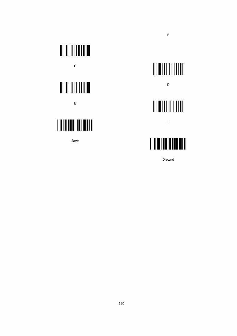
150
B
C
D
E
F
Save
Discard

151
APPENDIX C Symbology Charts-AIM ID
1D Symbologies
AIM
Symbology ID Possible
modifiers(m) Hex
All Symbologies 99
UPC 0,1,2,3,8,9,A,B,C
UPC-A ]E0 63
UPC-A with Add-On ]E3 63
UPC-A with Extended
Coupon Code ]E3 63
UPC-E ]E0 45
UPC-E with Add-On ]E3 45
UPC-E1 ]X0 45
EAN ]Em 0, 1, 3, 4 64
EAN-13 (including
Bookland EAN) ]E0 64
EAN-13 with Add-On ]E3 64
EAN-13 with Extended
Coupon Code ]E3 64
EAN-8 ]E4 44
EAN-8 with Add-On ]E3 44
Code 128 ]Cm 0, 1, 2, 4 6A
Telepen ]Bm 74

152
Code 39 (supports Full ASCII
mode) ]Am 0, 1, 3, 4, 5, 7 62
TCIF Linked Code 39
(TLC39) ]L2 54
Code 32 Pharmaceutical
(PARAF) ]X0 3C
Code 93 and 93i ]Gm 0-9, A-Z, a-m 69
Code 11 ]H3 68
2 of 5
China Post (Hong Kong 2
of 5) ]X0 51
Interleaved 2 of 5 ]Im 0, 1, 3 65
Matrix 2 of 5 ]X0 6D
NEC 2 of 5 ]X0 59
Straight 2 of 5 IATA ]Rm 0, 1, 3 66
Straight 2 of 5 Industrial ]S0 66
Codabar ]Fm 0-1 61
MSI ]Mm 0,1 67
GS1
GS1 DataBar ]em 0 79
GS1 DataBar Limited ]em 7B
GS1 DataBar Expanded ]em 7D
GS1-128 ]C1 49
Add AIM Code ID 5C81
Add Backslash 5C5C
Batch mode quantity 35

153
2D Symbologies
AIM
Symbology ID Possible modifiers (m) Hex
All Symbologies 99
Aztec Code ]zm 0-9, A-C 7A
Chinese Sensible Code (Han
Xin Code) ]X0 48
Codablock A ]O6 0, 1, 4, 5, 6 56
Codablock F ]Om 0, 1, 4, 5, 6 71
Code 49 ]Tm 0, 1, 2, 4 6C
GS1 ]em 0-3 79
GS1 Composite ]em 0-3 79
GS1 DataBar
Omnidirectional ]em 0-3 79
PDF417 ]Lm 0-2 72
MicroPDF417 ]Lm 0-5 52
MaxiCode ]Um 0-3 78
Data Matrix ]dm 0-6 77
QR Code ]Qm 0-6 73
Micro QR Code ]Qm 73

154
Postal Symbologies
AIM
Symbology ID Possible modifiers (m) Hex
All Symbologies 99
Australian Post ]X0 41
British Post ]X0 42
Canadian Post ]X0 43
China Post ]X0 51
InfoMail ]X0 2c
Intelligent Mail Bar Code ]X0 4D
Japanese Post ]X0 4A
KIX (Netherlands) Post ]X0 4B
Korea Post ]X0 3F
Planet Code ]X0 4C
Postal-4i ]X0 4E
Postnet ]X0 50
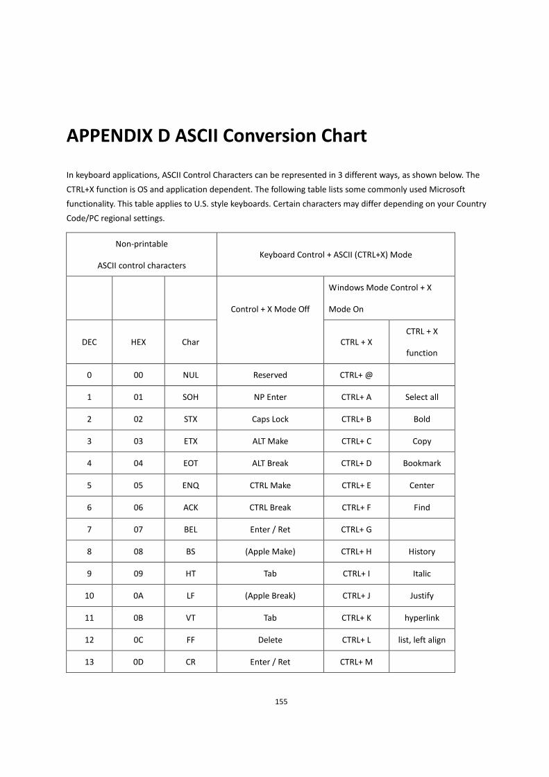
155
APPENDIX D ASCII Conversion Chart
In keyboard applications, ASCII Control Characters can be represented in 3 different ways, as shown below. The
CTRL+X function is OS and application dependent. The following table lists some commonly used Microsoft
functionality. This table applies to U.S. style keyboards. Certain characters may differ depending on your Country
Code/PC regional settings.
Non-printable
ASCII control characters Keyboard Control + ASCII (CTRL+X) Mode
Windows Mode Control + X
Mode On
DEC HEX Char
Control + X Mode Off
CTRL + X
CTRL + X
function
0 00 NUL Reserved CTRL+ @
1 01 SOH NP Enter CTRL+ A Select all
2 02 STX Caps Lock CTRL+ B Bold
3 03 ETX ALT Make CTRL+ C Copy
4 04 EOT ALT Break CTRL+ D Bookmark
5 05 ENQ CTRL Make CTRL+ E Center
6 06 ACK CTRL Break CTRL+ F Find
7 07 BEL Enter / Ret CTRL+ G
8 08 BS (Apple Make) CTRL+ H History
9 09 HT Tab CTRL+ I Italic
10 0A LF (Apple Break) CTRL+ J Justify
11 0B VT Tab CTRL+ K hyperlink
12 0C FF Delete CTRL+ L list, left align
13 0D CR Enter / Ret CTRL+ M
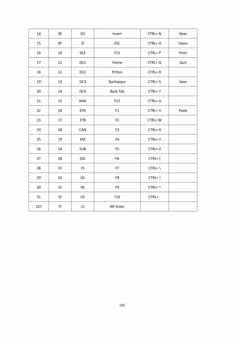
156
14 0E SO Insert CTRL+ N New
15 0F SI ESC CTRL+ O Open
16 10 DLE F11 CTRL+ P Print
17 11 DC1 Home CTRL+ Q Quit
18 12 DC2 PrtScn CTRL+ R
19 13 DC3 Backspace CTRL+ S Save
20 14 DC4 Back Tab CTRL+ T
21 15 NAK F12 CTRL+ U
22 16 SYN F1 CTRL+ V Paste
23 17 ETB F2 CTRL+ W
24 18 CAN F3 CTRL+ X
25 19 EM F4 CTRL+ Y
26 1A SUB F5 CTRL+ Z
27 1B ESC F6 CTRL+ [
28 1C FS F7 CTRL+ \
29 1D GS F8 CTRL+ ]
30 1E RS F9 CTRL+ ^
31 1F US F10 CTRL+ -
127 7F NP Enter

157
Lower ASCII Reference Table
Note: Windows Code page 1252 and lower ASCII use the same characters.
Printable Characters
DEC HEX Character DEC HEX Character DEC HEX Character
32 20 <SPACE> 64 40 @ 96 60 `
33 21 ! 65 41 A 97 61 a
34 22 ” 66 42 B 98 62 b
35 23 # 67 43 C 99 63 c
36 24 $ 68 44 D 100 64 d
37 25 % 69 45 E 101 65 e
38 26 & 70 46 F 102 66 f
39 27 ’ 71 47 G 103 67 g
40 28 ( 72 48 H 104 68 h
41 29 ) 73 49 I 105 69 i
42 2A * 74 4A J 106 6A j
43 2B + 75 4B K 107 6B k
44 2C , 76 4C L 108 6C l
45 2D - 77 4D M 109 6D m
46 2E . 78 4E N 110 6E n
47 2F / 79 4F O 111 6F o
48 30 0 80 50 P 112 70 p
49 31 1 81 51 Q 113 71 q
50 32 2 82 52 R 114 72 r
51 33 3 83 53 S 115 73 s
52 34 4 84 54 T 116 74 t
53 35 5 85 55 U 117 75 u
54 36 6 86 56 V 118 76 v

158
55 37 7 87 57 W 119 77 w
56 38 8 88 58 X 120 78 x
57 39 9 89 59 Y 121 79 y
58 3A : 90 5A Z 122 7A z
59 3B ; 91 5B [ 123 7B
60 3C < 92 5C \ 124 7C |
61 3D = 93 5D ] 125 7D
62 3E > 94 5E ^ 126 7E ~
63 3F ? 95 5F _ 127 7F

159
Extended ASCII Characters
DEC HEX CP 1252 ASCII Alternate Extended PS2 Scan
Code
128 80 € Ç up arrow 0x48
129 81 ü down arrow 0x50
130 82 é right arrow 0x4B
131 83 â left arrow 0x4D
132 84 ä Insert 0x52
133 85 à Delete 0x53
134 86 å Home 0x47
135 87 ç End 0x4F
136 88 ê Page Up 0x49
137 89 ë Page Down 0x51
138 8A è Right ALT 0x38
139 8B ï Right CTRL 0x1D
140 8C î Reserved n/a
141 8D ì Reserved n/a
142 8E Ž Ä Numeric Keypad Enter 0x1C
143 8F Å Numeric Keypad / 0x35
144 90 É F1 0x3B
145 91 ‘ æ F2 0x3C
146 92 ’ Æ F3 0x3D
147 93 ô F4 0x3E
148 94 ö F5 0x3F
149 95 • ò F6 0x40
150 96 – û F7 0x41
151 97 — ù F8 0x42

160
152 98 ÿ F9 0x43
153 99 Ö F10 0x44
154 9A Ü F11 0x57
155 9B ¢ F12 0x58
156 9C £ Numeric Keypad + 0x4E
157 9D ¥ Numeric Keypad - 0x4A
158 9E ž ₧ Numeric Keypad * 0x37
159 9F Caps Lock 0x3A
160 A0 á Num Lock 0x45
161 A1 í Left Alt 0x38
162 A2 ¢ ó Left Ctrl 0x1D
163 A3 £ ú Left Shift 0x2A
164 A4 ¤ ñ Right Shift 0x36
165 A5 ¥ Ñ Print Screen n/a
166 A6 ¦ Tab 0x0F
167 A7 § Shift Tab 0x8F
168 A8 ¨ Enter 0x1C
169 A9 © Esc 0x01
170 AA ¬ Alt Make 0x36
171 AB « Alt Break 0xB6
172 AC ¬ Control Make 0x1D
173 AD Control Break 0x9D
174 AE ® « Alt Sequence with 1 Character 0x36
175 AF » Ctrl Sequence with 1 Character 0x1D
176 B0 °
177 B1 ±
178 B2
179 B3

161
180 B4
181 B5 µ
182 B6
183 B7 ·
184 B8
185 B9
186 BA
187 BB »
188 BC
189 BD
190 BE
191 BF
192 C0 À
193 C1 Á
194 C2 Â
195 C3 Ã
196 C4 Ä
197 C5 Å í
198 C6 Æ
199 C7 Ç
200 C8 È
201 C9 É
202 CA Ê
203 CB Ë
204 CC Ì
205 CD Í
206 CE Î
207 CF Ï
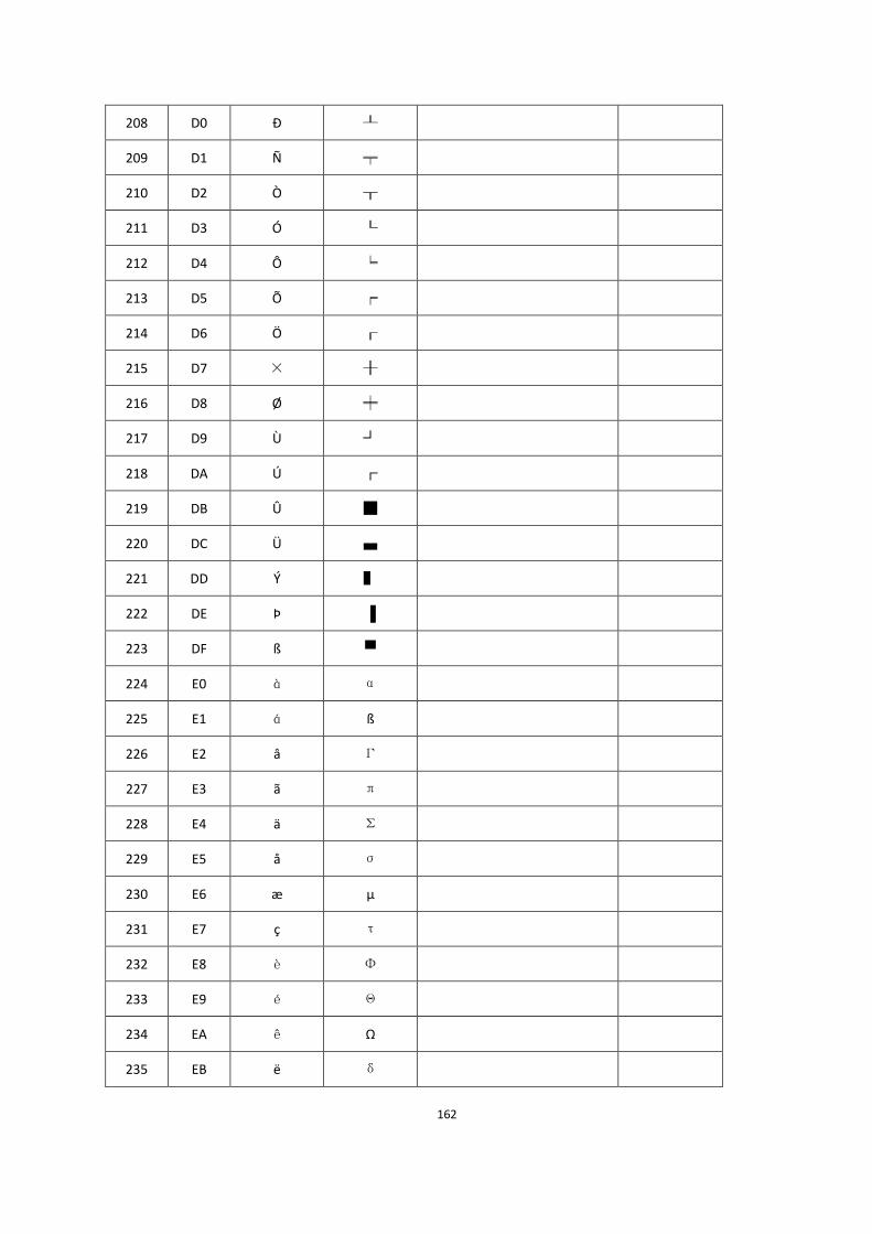
162
208 D0 Ð
209 D1 Ñ
210 D2 Ò
211 D3 Ó
212 D4 Ô
213 D5 Õ
214 D6 Ö
215 D7 ×
216 D8 Ø
217 D9 Ù
218 DA Ú
219 DB Û
220 DC Ü
221 DD Ý
222 DE Þ
223 DF ß
224 E0 à α
225 E1 á ß
226 E2 â Γ
227 E3 ã π
228 E4 ä Σ
229 E5 å σ
230 E6 æ µ
231 E7 ç τ
232 E8 è Φ
233 E9 é Θ
234 EA ê Ω
235 EB ë δ

163
236 EC ì
237 ED í φ
238 EE î ε
239 EF ï
240 F0 ð
241 F1 ñ ±
242 F2 ò
243 F3 ó
244 F4 ô ⌠
245 F5 õ ⌡
246 F6 ö ÷
247 F7 ÷
248 F8 ø °
249 F9 ù ·
250 FA ú ·
251 FB û
252 FC ü ⁿ
253 FD ý
254 FE þ
255 FF ÿ
Recommended