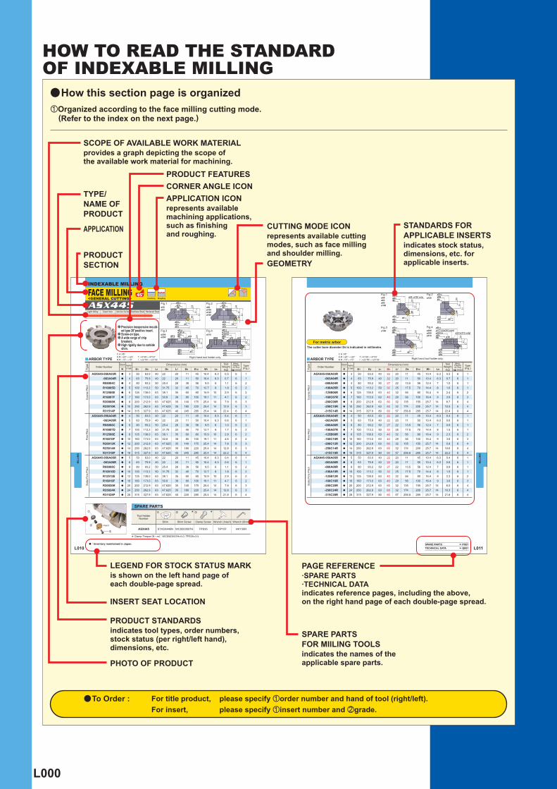
L000
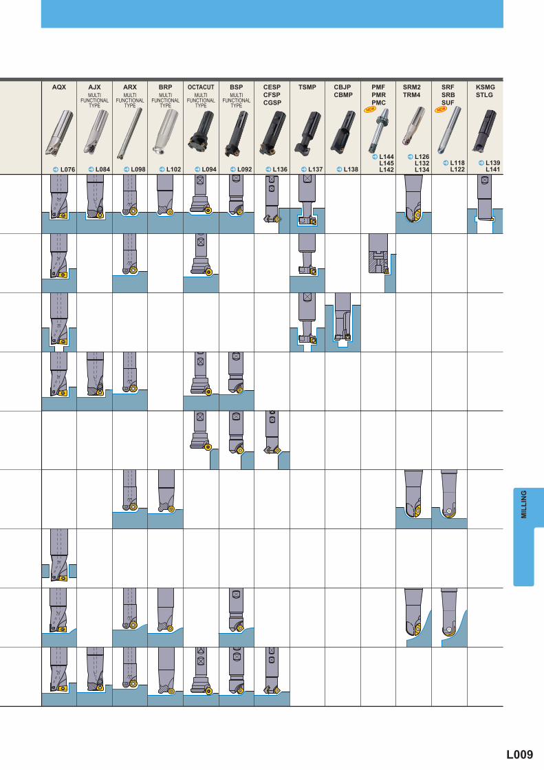
aHow this section page is organizedzOrganized according to the face milling cutting mode.
(Refer to the index on the next page.)
SCOPE OF AVAILABLE WORK MATERIALprovides a graph depicting the scope of the available work material for machining.
APPLICATION ICONrepresents available machining applications, such as fi nishing and roughing.
LEGEND FOR STOCK STATUS MARKis shown on the left hand page of each double-page spread.
PAGE REFERENCE·SPARE PARTS·TECHNICAL DATAindicates reference pages, including the above, on the right hand page of each double-page spread.
SPARE PARTS FOR MIILING TOOLSindicates the names of the applicable spare parts.
PRODUCT STANDARDSindicates tool types, order numbers, stock status (per right/left hand), dimensions, etc.
APPLICATION
TYPE/NAME OF PRODUCT
PRODUCT FEATURESCORNER ANGLE ICON
PRODUCT SECTION
CUTTING MODE ICONrepresents available cutting modes, such as face milling and shoulder milling.
STANDARDS FOR APPLICABLE INSERTSindicates stock status, dimensions, etc. for applicable inserts.GEOMETRY
INSERT SEAT LOCATION
PHOTO OF PRODUCT
HOW TO READ THE STANDARD OF INDEXABLE MILLING
a To Order : For title product, please specify zorder number and hand of tool (right/left). For insert, please specify zinsert number and xgrade.
L010
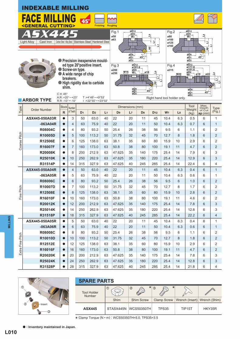
Light Alloy Cast Iron Carbon Steel · Alloy Steel Stainless Steel Hardened Steel ASX445
Type
Order Number Stock Number
of Teeth Dimensions (mm) Tool
Weight(kg)
Max. Depthof Cut
ap (mm) Type
(Fig.) R D1 D2 L1 D9 L7 D8 D12 W1 L8
Coa
rse
Pitc
h
ASX445-050A03R a 3 50 63.0 40 22 20 11 45 10.4 6.3 0.5 6 1-063A04R a 4 63 75.9 40 22 20 11 50 10.4 6.3 0.7 6 1
R08004C a 4 80 93.2 50 25.4 26 38 56 9.5 6 1.1 6 2
R10005D a 5 100 113.2 50 31.75 32 45 70 12.7 8 1.8 6 2
R12506E a 6 125 138.0 63 38.1 35 60 80 15.9 10 2.9 6 2
R16007F a 7 160 173.0 63 50.8 38 80 100 19.1 11 4.7 6 2
R20008K a 8 200 212.9 63 47.625 35 140 175 25.4 14 7.9 6 3
R25010K a 10 250 262.9 63 47.625 35 180 220 25.4 14 12.9 6 3R31514P a 14 315 327.9 63 47.625 40 245 285 25.4 14 22.4 6 4
Fine
Pitc
h
ASX445-050A04R a 4 50 63.0 40 22 20 11 45 10.4 6.3 0.4 6 1-063A05R a 5 63 75.9 40 22 20 11 50 10.4 6.3 0.6 6 1
R08006C a 6 80 93.2 50 25.4 26 38 56 9.5 6 1.0 6 2
R10007D a 7 100 113.2 50 31.75 32 45 70 12.7 8 1.7 6 2
R12508E a 8 125 138.0 63 38.1 35 60 80 15.9 10 2.8 6 2
R16010F a 10 160 173.0 63 50.8 38 80 100 19.1 11 4.6 6 2
R20012K a 12 200 212.9 63 47.625 35 140 175 25.4 14 7.8 6 3
R25014K a 14 250 262.9 63 47.625 35 180 220 25.4 14 12.8 6 3R31518P a 18 315 327.9 63 47.625 40 245 285 25.4 14 22.2 6 4
Ext
ra F
ine
Pitc
h
ASX445-050A05R a 5 50 63.0 40 22 20 11 45 10.4 6.3 0.4 6 1-063A06R a 6 63 75.9 40 22 20 11 50 10.4 6.3 0.6 6 1
R08008C a 8 80 93.2 50 25.4 26 38 56 9.5 6 1.1 6 2
R10010D a 10 100 113.2 50 31.75 32 45 70 12.7 8 1.8 6 2
R12512E a 12 125 138.0 63 38.1 35 60 80 15.9 10 2.9 6 2
R16016F a 16 160 173.0 63 50.8 38 80 100 19.1 11 4.7 6 2
R20020K a 20 200 212.9 63 47.625 35 140 175 25.4 14 7.8 6 3
R25024K a 24 250 262.9 63 47.625 35 180 220 25.4 14 12.8 6 3R31528P a 28 315 327.9 63 47.625 40 245 285 25.4 14 21.8 6 4
y
C H :45°A.R :+20°─+23°R.R :-13°─-10°
T :+4°49′─+9°53′I :+22°55′─+23°02′
Tool HolderNumber
* *
Shim Shim Screw Clamp Screw Wrench (Insert) Wrench (Shim)
ASX445 STASX445N WCS503507H TPS35 TIP15T HKY35R
z x c
x
z
c
øD8øD1øD2
45°
L7L1
L8ap
øD9øD12 øD12
W1øD9
L8L7
L1ap
45°øD8øD1øD2
W1
M16
L1L7
apL8
øD8øD1øD2
45°
øD9W1
L1L7
apL8
øD8øD1øD2
45°
øD9M20
ø177.8øD12
ø101.6
W1 ø18
ø101.6øD12
ø18ø22
ø50ø63
ø200ø250
ø80ø100ø125ø160
ø315
MIL
LIN
G
INDEXABLE MILLING
<GENERAL CUTTING>FACE MILLING
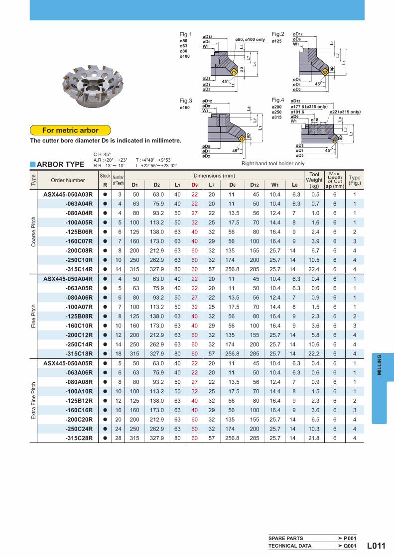
Right hand tool holder only. ARBOR TYPE
* Clamp Torque (N • m) : WCS503507H=5.0, TPS35=3.5
Fig.1
RoughingFinishing
Insert
SPARE PARTS
Fig.2
Fig.3 Fig.4Precision inexpensive mould- ed type 20°positive insert.Screw-on type.A wide range of chip breakers.High rigidity due to carbide shim.
a
aa
a
a : Inventory maintained in Japan.
L011
Type
Order Number Stock Number
of Teeth Dimensions (mm) Tool
Weight(kg)
Max. Depthof Cut
ap (mm) Type
(Fig.) R D1 D2 L1 D9 L7 D8 D12 W1 L8
Coa
rse
Pitc
h
ASX445-050A03R a 3 50 63.0 40 22 20 11 45 10.4 6.3 0.5 6 1-063A04R a 4 63 75.9 40 22 20 11 50 10.4 6.3 0.7 6 1
-080A04R a 4 80 93.2 50 27 22 13.5 56 12.4 7 1.0 6 1
-100A05R a 5 100 113.2 50 32 25 17.5 70 14.4 8 1.6 6 1
-125B06R a 6 125 138.0 63 40 32 56 80 16.4 9 2.4 6 2
-160C07R a 7 160 173.0 63 40 29 56 100 16.4 9 3.9 6 3
-200C08R a 8 200 212.9 63 60 32 135 155 25.7 14 6.7 6 4
-250C10R a 10 250 262.9 63 60 32 174 200 25.7 14 10.5 6 4-315C14R a 14 315 327.9 80 60 57 256.8 285 25.7 14 22.4 6 4
Fine
Pitc
h
ASX445-050A04R a 4 50 63.0 40 22 20 11 45 10.4 6.3 0.4 6 1-063A05R a 5 63 75.9 40 22 20 11 50 10.4 6.3 0.6 6 1
-080A06R a 6 80 93.2 50 27 22 13.5 56 12.4 7 0.9 6 1
-100A07R a 7 100 113.2 50 32 25 17.5 70 14.4 8 1.5 6 1
-125B08R a 8 125 138.0 63 40 32 56 80 16.4 9 2.3 6 2
-160C10R a 10 160 173.0 63 40 29 56 100 16.4 9 3.6 6 3
-200C12R a 12 200 212.9 63 60 32 135 155 25.7 14 5.8 6 4
-250C14R a 14 250 262.9 63 60 32 174 200 25.7 14 10.6 6 4-315C18R a 18 315 327.9 80 60 57 256.8 285 25.7 14 22.2 6 4
Ext
ra F
ine
Pitc
h
ASX445-050A05R a 5 50 63.0 40 22 20 11 45 10.4 6.3 0.4 6 1-063A06R a 6 63 75.9 40 22 20 11 50 10.4 6.3 0.6 6 1
-080A08R a 8 80 93.2 50 27 22 13.5 56 12.4 7 0.9 6 1
-100A10R a 10 100 113.2 50 32 25 17.5 70 14.4 8 1.5 6 1
-125B12R a 12 125 138.0 63 40 32 56 80 16.4 9 2.3 6 2
-160C16R a 16 160 173.0 63 40 29 56 100 16.4 9 3.6 6 3
-200C20R a 20 200 212.9 63 60 32 135 155 25.7 14 6.5 6 4
-250C24R a 24 250 262.9 63 60 32 174 200 25.7 14 10.3 6 4-315C28R a 28 315 327.9 80 60 57 256.8 285 25.7 14 21.8 6 4
C H :45°A.R :+20°─+23°R.R :-13°─-10°
T :+4°49′─+9°53′I :+22°55′─+23°02′y
SPARE PARTS P001 TECHNICAL DATA Q001
L1L7
apL8
øD8øD1øD2
45°
øD9ø101.6
W1 ø18
L7 L7
øD9W1
øD9øD12
W1
L7
øD9øD12
W1
L1
ap ap
45°
øD2øD1
øD845°
øD2øD1øD8
L1
øD12
L8
L8
ap
L1
45°øD1øD8
øD2
L8 ø22ø177.8øD12
ø50ø63ø80ø100
ø125
ø160 ø200ø250ø315
MIL
LIN
G
(ø315 only)
For metric arborThe cutter bore diameter D9 is indicated in millimetre.
ARBOR TYPE Right hand tool holder only.
Fig.1 Fig.2
Fig.3 Fig.4(ø315 only)
ø80, ø100 only
L001
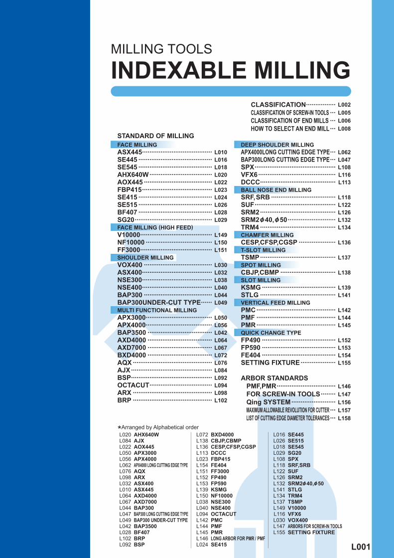
L010L016L018L020L022L023L024L026L028L029
L149L150L151
L030L032L038L040L044L049
L050L056L042L064L067L072L076L084L092L094L098L102
L002L005L006L008
L062L047L108L116L113
L118L122L126L132L134
L136
L137
L138
L139L141
L142L144L145
L152L153L154L155
L146L147L156L157L158
L020L084L022L050L056L062L076L098L032L010L064L067L044L047L049L042L028L102L092
L072L138L136L113L023L154L151L152L153L139L150L038L040L094L142L144L145L146L024
L016L026L018L029L108L118L122L126L132L141L134L137L149L116L030L147L155
AHX640WAJXAOX445APX3000APX4000 APX4000 LONG CUTTING EDGE TYPE AQXARXASX400ASX445AXD4000AXD7000BAP300 BAP300 LONG CUTTING EDGE TYPE BAP300 UNDER-CUT TYPE BAP3500BF407BRPBSP
BXD4000CBJP,CBMPCESP,CFSP,CGSPDCCCFBP415FE404FF3000FP490FP590KSMGNF10000NSE300NSE400OCTACUTPMCPMFPMR LONG ARBOR FOR PMR / PMF SE415
SE445SE515SE545SG20SPXSRF,SRBSUFSRM2SRM2&40,&50STLGTRM4TSMPV10000VFX6VOX400 ARBORS FOR SCREW-IN TOOLS SETTING FIXTURE
FACE MILLING ASX445 ...................................... SE445 ........................................ SE545 ........................................ AHX640W .................................. AOX445 ..................................... FBP415 ...................................... SE415 ........................................ SE515 ........................................ BF407 ........................................ SG20 .......................................... FACE MILLING (HIGH FEED) V10000 ....................................... NF10000 .................................... FF3000 ....................................... SHOULDER MILLING VOX400 ..................................... ASX400 ...................................... NSE300 ...................................... NSE400 ...................................... BAP300 ..................................... BAP300UNDER-CUT TYPE ...... MULTI FUNCTIONAL MILLING APX3000 .................................... APX4000 .................................... BAP3500 ................................... AXD4000 ................................... AXD7000 ................................... BXD4000 ................................... AQX ........................................... AJX ............................................ BSP ............................................ OCTACUT .................................. ARX ........................................... BRP ...........................................
DEEP SHOULDER MILLING APX4000LONG CUTTING EDGE TYPE ... BAP300LONG CUTTING EDGE TYPE ... SPX ............................................ VFX6 .......................................... DCCC ......................................... BALL NOSE END MILLING SRF,SRB ................................... SUF ............................................ SRM2 ......................................... SRM2&40,&50 .......................... TRM4 ......................................... CHAMFER MILLING CESP,CFSP,CGSP .................... T-SLOT MILLING TSMP ......................................... SPOT MILLING CBJP,CBMP .............................. SLOT MILLING KSMG ........................................ STLG ......................................... VERTICAL FEED MILLING PMC ........................................... PMF ........................................... PMR ........................................... QUICK CHANGE TYPE FP490 ........................................ FP590 ........................................ FE404 ........................................ SETTING FIXTURE ...................
CLASSIFICATION ................CLASSIFICATION OF SCREW-IN TOOLS ...CLASSIFICATION OF END MILLS ...HOW TO SELECT AN END MILL ...
STANDARD OF MILLING
MILLING TOOLS
INDEXABLE MILLING
*Arranged by Alphabetical order
ARBOR STANDARDS PMF,PMR ................................ FOR SCREW-IN TOOLS ........ Qing SYSTEM ........................ MAXIMUM ALLOWABLE REVOLUTION FOR CUTTER ... LIST OF CUTTING EDGE DIAMETER TOLERANCES ...
L002
MIL
LIN
GINDEXABLE MILLING
9
7°
11.5
15°
8.5
15°
8.5
7.5
5.5
6
15°
6
40°
8
45°
45°
45°
45°
45°
45°
45°
15°
15°
15°
7°
·Ø50·Ø63·Ø80·Ø100·Ø125·Ø160·Ø200·Ø250·Ø315
ASX445
·Ø80·Ø100·Ø125·Ø160·Ø200·Ø250·Ø315
FBP415
AHX640W
·Ø80·Ø100·Ø125·Ø160·Ø200·Ø250·Ø315
BF407
·Ø80·Ø100·Ø125·Ø160·Ø200·Ø250·Ø315
·Ø100·Ø125·Ø160·Ø200·Ø250
·Ø80·Ø100·Ø125·Ø160
·Ø100·Ø125·Ø160
ASX445@
SE445@
FBP415@
SE415@
SE515@
BF407@
SE545@
^
^
^
^
^
^
^
L010
L016
L024
L026
L028
L018
L023
40°
·Ø80·Ø100·Ø125·Ø160·Ø200·Ø250·Ø315
AHX640W^ L020
AOX445
45°
·Ø63·Ø80·Ø100·Ø125·Ø160·Ø200
AOX445^ L022
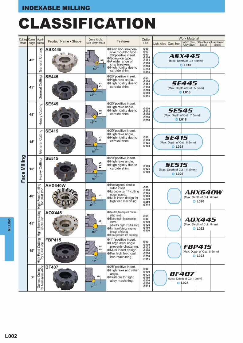
CLASSIFICATIONHardened
SteelStainless
SteelCast IronLight AlloyFeatures Cutter
Dia.Corner Angle,
Max. Depth of CutProduct Name • ShapeCornerAngle
CuttingMode
Appli-cation
Work MaterialG
ener
al C
uttin
gHi
gh F
eed
Cutti
ngfo
r Cas
t Iro
nG
ener
al C
uttin
gH
eavy
Cut
ting
Gen
eral
Cut
ting
Hea
vy C
uttin
gGe
nera
l Cut
ting
for A
lumini
um A
lloy
Face
Mill
ing
(Max. Depth of Cut : 6mm)
(Max. Depth of Cut : 5.5mm)
(Max. Depth of Cut : 8.5mm)
(Max. Depth of Cut : 8.5mm)
(Max. Depth of Cut : 11.5mm)
(Max. Depth of Cut : 9mm)
(Max. Depth of Cut : 7.5mm)
SE445
SE545
SE415
SE515
a
aa
a
a
a
a
a
a
a
a
a
a
a
a
a
a
a
a
a
a
a
a
Precision inexpen-sive moulded type 20°positive insert.Screw-on type.A wide range of chip breakers.High rigidity due to carbide shim.
11°positive insert.Large axial angle prevents chattering.Multi insert design.For high feed cast iron machining.
High
Fee
d Cu
tting
for C
ast I
ron
(Max. Depth of Cut : 6mm)
(Max. Depth of Cut : 8mm)
25°positive insert.High rake and relief angle.Suitable for light alloy machining.
20°positive insert.High rake angle.High rigidity due to carbide shim.
20°positive insert.High rake angle.High rigidity due to carbide shim.
20°positive insert.High rake angle.High rigidity due to carbide shim.
20°positive insert.High rake angle.High rigidity due to carbide shim.
Carbon Steel, Alloy Steel
High
effic
iency
cuttin
gfor
cast
iron
a
a
a
Heptagonal doublesided insert.Economical 14 cutting edge inserts.Multi insert design forhigh feed machining.
a
a
a
a
Solid CBN octagonal doublesided insert.Economical 16 cutting edgeinserts.(when the depth of cut is 3mm)For high efficiency roughingthrough to finishing. Easy operation and cleansing.
L003
MIL
LIN
G
82
9
4°
0.5
90°
0.5
90°
1.5
60.
3
90°
9
3°
8
0°
0°
0°
0°
0°
0°
4°
─
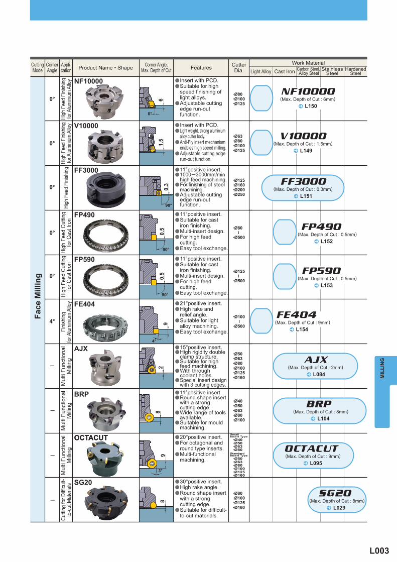
·Ø125·Ø160·Ø200·Ø250
FF3000
·Ø80
·Ø500
–
·Ø125
·Ø500
–
·Ø100
·Ø500
–
FP490
FP590
FE404
·Ø50·Ø63·Ø80·Ø100·Ø125·Ø160
AJX
NF10000
V10000
·Ø80·Ø100·Ø125
·Ø63·Ø80·Ø100·Ø125
^
FF3000@
AJX
^
V10000
^
NF10000@
^
FE404@
^
FP490@
^
L151
L149
L150
L154
L152
L153
FP590@
─·Ø40·Ø50·Ø63·Ø80·Ø100
BRP@
^ L084
^ L104
─
·Ø40·Ø50·Ø63·Ø80
·Ø50·Ø63·Ø80·Ø100·Ø125·Ø160
OCTACUT@OCTACUT
^ L095
OCTACUT
SG20·Ø80·Ø100·Ø125·Ø160
SG20@─
^ L029
High
Fee
d Cu
tting
for C
ast I
ron
Fini
shin
gfo
r Alu
min
ium
Allo
yHi
gh F
eed
Finis
hing
High
Fee
d Fi
nishin
gfo
r Alum
inium
Allo
yHi
gh F
eed
Finis
hing
for A
lumini
um A
lloy
High
Fee
d Cu
tting
for C
ast I
ron
Mul
ti Fu
nctio
nal
Milli
ngM
ulti
Func
tiona
lM
illing
Mul
ti Fu
nctio
nal
Milli
ng
Face
Mill
ing
(Max. Depth of Cut : 0.3mm)
(Max. Depth of Cut : 2mm)
(Max. Depth of Cut : 1.5mm)
(Max. Depth of Cut : 6mm)
(Max. Depth of Cut : 9mm)
(Max. Depth of Cut : 0.5mm)
(Max. Depth of Cut : 0.5mm)
(Max. Depth of Cut : 8mm)
StainlessSteelCast IronLight Alloy
Features CutterDia.
Corner Angle,Max. Depth of CutProduct Name • ShapeCorner
AngleCuttingMode
Appli-cation
Work Material
BRP
aa
a
a
a
a
a
a
a
a
a
a
a
a
aa
a
a
a
a
a
a
a
a
a
a
a
a
a
a
11°positive insert.1000─3000mm/min high feed machining.For finishing of steel machining.Adjustable cutting edge run-out function.
11°positive insert.Suitable for cast iron finishing.Multi-insert design.For high feed cutting.Easy tool exchange.
11°positive insert.Suitable for cast iron finishing.Multi-insert design.For high feed cutting.Easy tool exchange.
15°positive insert.High rigidity double clamp structure.Suitable for high feed machining.With through coolant holes.Special insert design with 3 cutting edges.
Insert with PCD.Suitable for high speed finishing of light alloys.Adjustable cutting edge run-out function.
Insert with PCD.Light weight, strong aluminium alloy cutter body.Anti-Fly insert mechanism enables high speed milling. Adjustable cutting edge run-out function.
21°positive insert.High rake and relief angle.Suitable for light alloy machining.Easy tool exchange.
aa
a
a
11°positive insert.Round shape insert with a strong cutting edge.Wide range of tools available.Suitable for mould machining.
HardenedSteel
Carbon Steel, Alloy Steel
(Max. Depth of Cut : 9mm)
Small Insert Type
StandardInsert Type
a
a
a
20°positive insert.For octagonal andround type inserts.Multi-functionalmachining.
Cutti
ng fo
r Diffi
cult-
to-c
ut M
ater
ials
(Max. Depth of Cut : 8mm)
a
a
a
a
30°positive insert.High rake angle.Round shape insert with a strong cutting edge. Suitable for difficult-to-cut materials.
L004
MIL
LIN
GINDEXABLE MILLING
15
90°
1090°
12.5
90°
17
90°
10
90°
15
90°
21
90°
15.5
90°
10
90°
0°
0°
0°
0°
0°
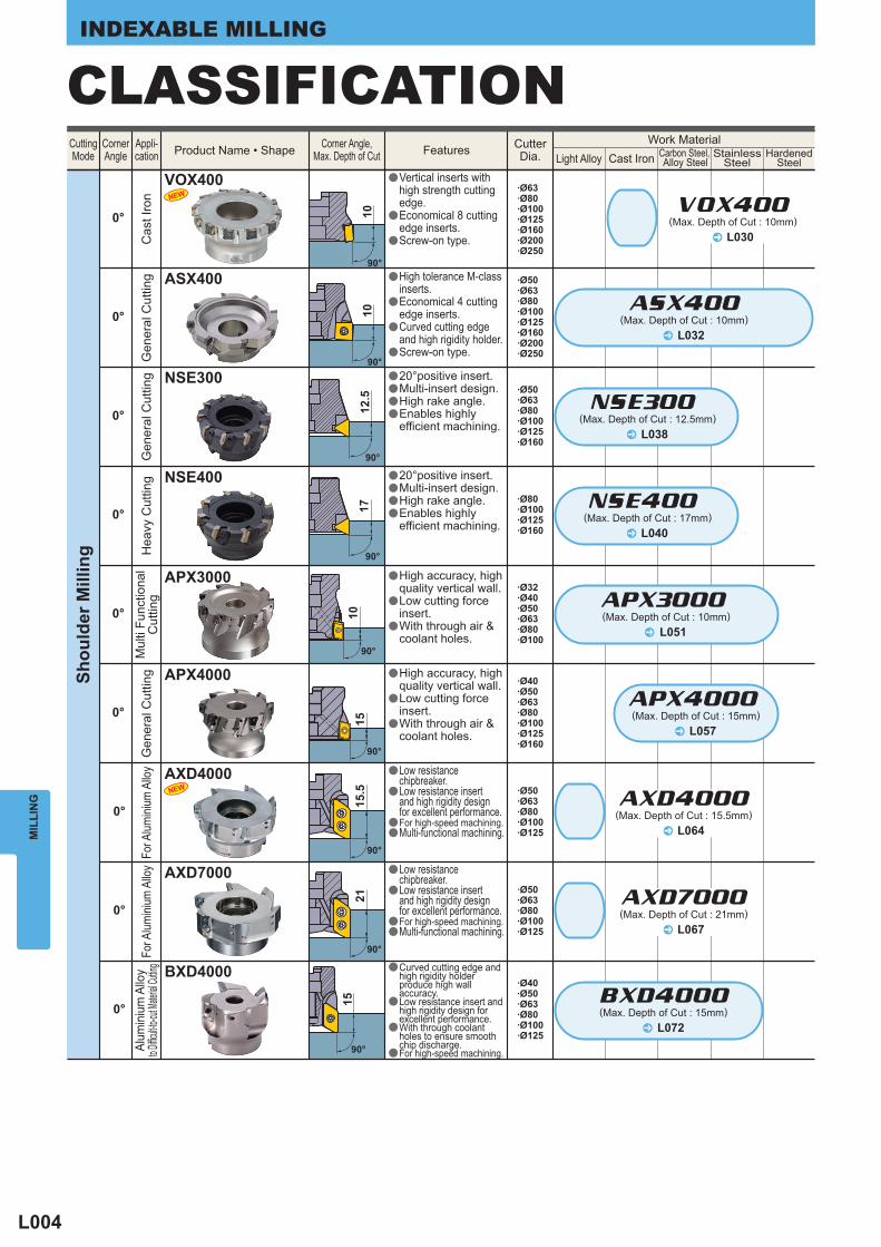
ASX400
VOX400
·Ø50·Ø63·Ø80·Ø100·Ø125·Ø160
·Ø80·Ø100·Ø125·Ø160
·Ø40·Ø50·Ø63·Ø80·Ø100·Ø125·Ø160
·Ø32·Ø40·Ø50·Ø63·Ø80·Ø100
·Ø50·Ø63·Ø80·Ø100·Ø125·Ø160·Ø200·Ø250
·Ø63·Ø80·Ø100·Ø125·Ø160·Ø200·Ø250
0°
ASX400
NSE400@
NSE300@
APX3000@
APX4000@
APX3000
APX4000
^
^
L032
L040
^ L051
^ L057
L038^
0°
0°
0°
BXD4000
AXD7000
·Ø40·Ø50·Ø63·Ø80·Ø100·Ø125
·Ø50·Ø63·Ø80·Ø100·Ø125
·Ø50·Ø63·Ø80·Ø100·Ø125
^
BXD4000L072
^ L067
AXD7000
^ L064
AXD4000
^ L030
VOX400
AXD4000NEW
NEW
CLASSIFICATIONSh
ould
er M
illin
g
Gen
eral
Cut
ting
Hea
vy C
uttin
gG
ener
al C
uttin
gC
ast I
ron
Mul
ti Fu
nctio
nal
Cut
ting
Gen
eral
Cut
ting
(Max. Depth of Cut : 10mm)
(Max. Depth of Cut : 17mm)
(Max. Depth of Cut : 10mm)
(Max. Depth of Cut : 15mm)
(Max. Depth of Cut : 12.5mm)
For A
lumini
um A
lloy
For A
lumini
um A
lloy
StainlessSteelCast IronLight Alloy
Features CutterDia.
Corner Angle,Max. Depth of CutProduct Name • ShapeCorner
AngleCuttingMode
Appli-cation
Work Material
NSE300
NSE400
a
a
a
a
a
a
a
a
a
a
a
a
20°positive insert.Multi-insert design.High rake angle.Enables highly efficient machining.
20°positive insert.Multi-insert design.High rake angle.Enables highly efficient machining.
a
a
a
High accuracy, high quality vertical wall.Low cutting forceinsert.With through air & coolant holes.
a
a
a
High accuracy, high quality vertical wall.Low cutting forceinsert.With through air & coolant holes.
High tolerance M-class inserts.Economical 4 cutting edge inserts.Curved cutting edge and high rigidity holder.Screw-on type.
a
a
a
Vertical inserts with high strength cutting edge.Economical 8 cutting edge inserts.Screw-on type.
HardenedSteel
Carbon Steel, Alloy Steel
Alum
iniu
m A
lloy
to Diffic
ult-to-c
ut Mate
rial Cu
tting
(Max. Depth of Cut : 15mm)
a
a
a
a
Curved cutting edge and high rigidity holder produce high wall accuracy.Low resistance insert and high rigidity design for excellent performance.With through coolant holes to ensure smooth chip discharge.For high-speed machining.
a
a
aa
Low resistance chipbreaker.Low resistance insert and high rigidity design for excellent performance.For high-speed machining.Multi-functional machining.
a
a
aa
Low resistance chipbreaker.Low resistance insert and high rigidity design for excellent performance.For high-speed machining.Multi-functional machining.
(Max. Depth of Cut : 21mm)
(Max. Depth of Cut : 15.5mm)
(Max. Depth of Cut : 10mm)
L005
MIL
LIN
G
10
90°
10
90°
15
90°
27.
4─18
ASX400
APX3000
AQX
APX4000
L034^
L052^
L058^
L078^
AJX
NEW
NEW
NEW
ARX
SRM2
SUF
SRF
PMC
L088^
L099^
L128^
L142^
L123^
L119^
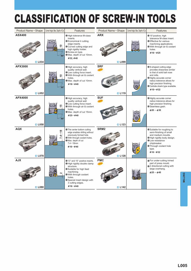
CLASSIFICATION OF SCREW-IN TOOLSFeatures Features
a
a
a
a
a
High tolerance M-class inserts.Economical 4 cutting edge inserts.Curved cutting edge and high rigidity holder.Screw-on type.Max. depth of cut 10mm.&32, &40
a
a
a
a
High accuracy, highquality vertical wall.Low cutting force insert.With through air & coolant holes.Max. depth of cut 10mm.&16─&40
a
a
a
a
High accuracy, highquality vertical wall.Low cutting force insert.With through air & coolant holes.Max. depth of cut 15mm.&25─&40
a
a
a
The center bottom cuttingedge enables drilling without previously formed hole.With through coolant holes.Max. depth of cut 7.4─18mm&16─&40
a
a
a
a
a
13° and 15° positive inserts.High rigidity double clamp structure.Suitable for high feed machining.With through coolant holes.Special insert design with 3 cutting edges.&16─&40
a
a
a
15°positive, high tolerance M-class insert.Effective for various machining applications.With through air & coolant holes.&16─&25
a
a
a
a
Suitable for roughing to semi-finishing of small and medium moulds.High rigidity body design.Low resistance chipbreaker.Through coolant hole type.&16─&32
a
a
For under-cutting trimedpart of press mould.2 directional cutting with large overhang.&25 ─ &40
Corner Angle, Max. Depth of Cut Corner Angle, Max. Depth of CutProduct Name • Shape Product Name • Shape
a
a
a
S-shaped cutting edge provides sharpness similar to that of solid ball nose end mills.Highly accurate corner radius tolerance allows for high precision finishing.Carbide shank type available.&10─&32
a
a
Highly accurate corner radius tolerance allows for high precision finishing.Seamless gash.&20 ─ &30
L006
MIL
LIN
GINDEXABLE MILLING
10
90°12
.5( N
SE
300)
17
( NS
E40
0)9
90°
21
90°
15
90°
10
90°
15
90°
11
90°
90°
58─
261
90°
27─
93
90°
6
45°
5.5
45°
17.6─
557.4
─ 23
28
45°
31─
90
90°
L034
L038L040
L074
L042
L047
^
^^
^
L050^
^L056L062
^
^
^L044^
L012
L017
L076
L086
^
^
^
^
ASX400
NSE300 NSE400
APX3000
ASX445
SE445
AJX
AQX
BXD4000
BAP3500
BAP300BAP300
APX4000APX4000
L108^
SPX
L064L067
^^
AXD4000AXD7000
NEW
L113^
L116^
DCCC
VFX6
L022^
AOX445
NEW
CLASSIFICATION
Long Cutting Edge
Corner Angle, Max. Depth of Cut Features Features
a
a
a
a
a
a
aa
a
a
a
a
a
a
a
a
a
a
a
a
a
a
a
a
a
a
a
a
a
a
a
aa
a
a
a
a
a
a
a
a
aa
High tolerance M-class inserts.Economical 4 cutting edge inserts.Curved cutting edge and high rigidity holder.Screw-on type.Max. depth of cut 10mm.&40─&80
Precision inexpensive moulded type 20°positive insert.Screw-on type.A wide range of chip breakers.High rigidity due to carbide shim.Max. depth of cut 6mm.&50─&80
a
a
Low cutting resistance due to the use of wavy inserts.Suitable for heavy cutting due to holder rigidity.&50
20°positive insert.High rake angle.High rigidity due to carbide shim.Max. depth of cut 5.5mm.&50─&80
13° and 15° positive inserts.High rigidity double clamp structure.Suitable for high feed machining.With through coolant holes.Special insert design with 3 cutting edges.&16─&63
The center bottom cuttingedge enables drilling without previously formed hole.With through coolant holes.Max. depth of cut Standard Edge Type=55mm Short Edge Type=23mm&16─&50
20°positive insert.Multi-insert design.High rake angle.Enables highly efficient machining.Max. depth of cutNSE300=12.5mmNSE400=17mm&50, &63
Curved cutting edge and high rigidity holder produce high wall accuracy.Low resistance insert and high rigidity design for excellent performance.With through coolant holes to ensure smooth chip discharge.For high-speed machining.Max. depth of cut 15mm &20─&40
High rake angle.Contour machining is possible.Through coolant type.Max. depth of cut 11mm.&16─&40
High accuracy, highquality vertical wall.Low cutting force insert.With through air & coolant holes.Max. depth of cut 10mm.&12─&63
a
a
a
a
High accuracy, highquality vertical wall.Low cutting force insert.With through air & coolant holes.Max. depth of cut 15mm.&25─&63
11° positive insert.Inserts with wiper edges produce optimal finished surface. Multi insert design for high feed machining.BAP300 &10─&63BAP300 Long Cutting Edge&20─&40
a
a
a
a
a
Low resistance chipbreaker.Low resistance insert and high rigidity design for excellent performance.For high-speed machining.Multi-functional machining.Max. depth of cut 21mm &32, &40
a
a
Different helical flute angles prevents chattering.Suitable for heavy cutting due to holder rigidity.&25─&50
a
a
a
Vertical inserts with high strength cutting edge.Screw-on type.High efficiency milling titanium alloys.&63─&100
Corner Angle, Max. Depth of Cut
( Standa
rd Edge
Type)
( Short
Edge
Type)
a
a
a
a
Solid CBN octagonaldouble sided insert.Economical 16 cuttingedge inserts.(when the depth of cut is 3mm)For high efficiencyroughing through tofinishing. Easy operation andcleansing.
Product Name • ShapeProduct Name • Shape
L007
MIL
LIN
G
9
3°
7
45°
10.2
( 30°
)8.
3(45
°)5.
9(60
°)
30°45°60°
11 14 18
17
L136
L137
L138
^
^
^
L126
L134
L141
L139
^
^
^
^
SRM2
TRM4
STLG
KSMG
L132^
SRM2&40/&50
L118^
SRF•SRBCESP•CFSP•CGSP
TSMP
CBJP•CBMP
L092^
BSPL094^
OCTACUT
L144^
PMF
L102^
BRPL098^
ARX
L145^
PMR
L122^
SUFNEW
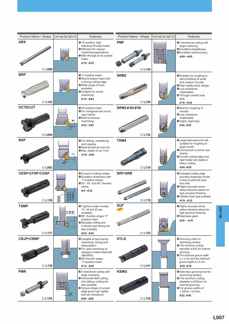
Features Corner Angle, Max. Depth of Cut Features
a
a
a
a
a
a
a
a
a
a
a
a
a
a
a
a
a
a
a
a
a
a
Grooving cutter for machining centers.The minimum cutting diameter is &22 for internal grooving.The minimum groove width is 1.2 mm and the maximum groove depth is 4.5 mm.&22, &38
Side face grooving tool for machining centers.The minimum cutting diameter is &25mm for internal grooving.For groove widths of 1.25mm─6.3mm.&25, &40
a
a
a
Best for roughing of moulds.Low resistance chipbreaker.Highly rigid body.&40, &50
a
a
a
a
a
S-shaped cutting edge provides sharpness similar to that of solid ball nose end mills.Highly accurate corner radius tolerance allows for high precision finishing.Carbide shank type available.&10─&32
Covers 5 cutting modes.Excellent sharpness with 11°positive inserts.30°, 45° and 60° chamfer series.&4─&32
T-groove order number 14, 18 and 22 are available.86° rhombic shape 11° positive insert.Shoulder milling and inversed spot facing are also possible.&25─&40
Capable of spot facing machining, boring and interpolation.For seat machining of hexagon socket head bolt (M8-M30).86°rhombic shape 11°positive insert.&14─&48
Suitable for roughing to semi-finishing of small and medium moulds.High rigidity body design.Low resistance chipbreaker.Through coolant hole type.&16─&30
Large ball-nose end mill suitable for roughing of large mould.Economical 3-corner-use inserts.Curved cutting edge and rigid holder are stable in heavy cutting.&40, &50
a
a
a
For drilling, chamfering and copying.Multi-functional end millMax. depth of cut 7mm.&10─&40
a
a
a
20°positive insert.For octagonal and round type inserts.Multi-functional machining.&32─&63
a
a
a
2 directional cutting with large overhang.Excellent straightness.Excellent wall accuracy.&50─&80
Corner Angle, Max. Depth of Cut
a
a
a
a
11°positive insert.Round shape insert with a strong cutting edge.Wide range of tools available.Suitable for mould machining.&12─&63
Product Name • Shape Product Name • Shape
a
a
a
15°positive, high tolerance M-class insert.Effective for various machining applications.With through air & coolant holes.&10─&25
a
a
a
2 directional cutting with large overhang.Horizontal feed cutting and oblique cutting are also possible.Unique shape of curved edge gives high rigidity and low resistance.&50─&80
Highly accurate corner radius tolerance allows for high precision finishing.Seamless gash.&20 ─ &30
L008
MIL
LIN
GINDEXABLE MILLING
ASX445 SE445 AOX445ASX400 NSE300NSE400
BAP300 BAP3500 BXD4000
^ L034^ L038
L040 ^ L044^ L062
APX3000APX4000
^ L050L056 ^ L042 ^ L074^ L047
^ L064L067
SPXDCCCVFX6
^ L108L113L116 ^ L012 ^ L022^ L017
AXD4000AXD7000
NEW
NEW
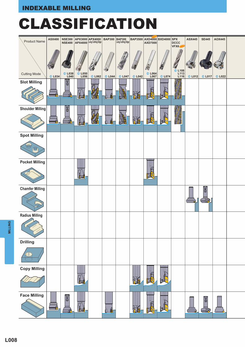
CLASSIFICATIONProduct Name
Cutting Mode
Slot Milling
Shoulder Milling
Spot Milling
Pocket Milling
Chamfer Milling
Radius Milling
Drilling
Copy Milling
Face Milling
BAP300Long Cutting Edge
APX4000Long Cutting Edge
L009
MIL
LIN
G
AJX BRP BSP CESPCFSPCGSP
TSMP CBJPCBMP
PMFPMRPMC
SRFSRBSUF
KSMGSTLG
SRM2TRM4
^ L084 ^ L102
ARX
^ L098 ^ L094 ^ L092 ^ L136 ^ L137 ^ L138
^ L144L145L142
^ L126L132L134
^ L118L122
^ L139L141
OCTACUTAQX
^ L076
NEW NEW
MULTIFUNCTIONAL
TYPE
MULTIFUNCTIONAL
TYPE
MULTIFUNCTIONAL
TYPE
MULTIFUNCTIONAL
TYPE
MULTIFUNCTIONAL
TYPE
L010
Light Alloy Cast Iron Carbon Steel · Alloy Steel Stainless Steel Hardened Steel ASX445
Type
Order Number Stock Number
of Teeth Dimensions (mm) Tool
Weight(kg)
Max. Depthof Cut
ap (mm) Type
(Fig.) R D1 D2 L1 D9 L7 D8 D12 W1 L8
Coa
rse
Pitc
h
ASX445-050A03R a 3 50 63.0 40 22 20 11 45 10.4 6.3 0.5 6 1-063A04R a 4 63 75.9 40 22 20 11 50 10.4 6.3 0.7 6 1
R08004C a 4 80 93.2 50 25.4 26 38 56 9.5 6 1.1 6 2
R10005D a 5 100 113.2 50 31.75 32 45 70 12.7 8 1.8 6 2
R12506E a 6 125 138.0 63 38.1 35 60 80 15.9 10 2.9 6 2
R16007F a 7 160 173.0 63 50.8 38 80 100 19.1 11 4.7 6 2
R20008K a 8 200 212.9 63 47.625 35 140 175 25.4 14 7.9 6 3
R25010K a 10 250 262.9 63 47.625 35 180 220 25.4 14 12.9 6 3R31514P a 14 315 327.9 63 47.625 40 245 285 25.4 14 22.4 6 4
Fine
Pitc
h
ASX445-050A04R a 4 50 63.0 40 22 20 11 45 10.4 6.3 0.4 6 1-063A05R a 5 63 75.9 40 22 20 11 50 10.4 6.3 0.6 6 1
R08006C a 6 80 93.2 50 25.4 26 38 56 9.5 6 1.0 6 2
R10007D a 7 100 113.2 50 31.75 32 45 70 12.7 8 1.7 6 2
R12508E a 8 125 138.0 63 38.1 35 60 80 15.9 10 2.8 6 2
R16010F a 10 160 173.0 63 50.8 38 80 100 19.1 11 4.6 6 2
R20012K a 12 200 212.9 63 47.625 35 140 175 25.4 14 7.8 6 3
R25014K a 14 250 262.9 63 47.625 35 180 220 25.4 14 12.8 6 3R31518P a 18 315 327.9 63 47.625 40 245 285 25.4 14 22.2 6 4
Ext
ra F
ine
Pitc
h
ASX445-050A05R a 5 50 63.0 40 22 20 11 45 10.4 6.3 0.4 6 1
-063A06R a 6 63 75.9 40 22 20 11 50 10.4 6.3 0.6 6 1
R08008C a 8 80 93.2 50 25.4 26 38 56 9.5 6 1.1 6 2
R10010D a 10 100 113.2 50 31.75 32 45 70 12.7 8 1.8 6 2
R12512E a 12 125 138.0 63 38.1 35 60 80 15.9 10 2.9 6 2
R16016F a 16 160 173.0 63 50.8 38 80 100 19.1 11 4.7 6 2
R20020K a 20 200 212.9 63 47.625 35 140 175 25.4 14 7.8 6 3
R25024K a 24 250 262.9 63 47.625 35 180 220 25.4 14 12.8 6 3R31528P a 28 315 327.9 63 47.625 40 245 285 25.4 14 21.8 6 4
y
C H :45°A.R :+20°─+23°R.R :-13°─ -10°
T :+4°49′─+9°53′I :+22°55′─+23°02′
Tool HolderNumber
* *
Shim Shim Screw Clamp Screw Wrench (Insert) Wrench (Shim)
ASX445 STASX445N WCS503507H TPS35 TIP15T HKY35R
z x c
x
z
c
øD8øD1øD2
45°
L7L1
L8ap
øD9øD12 øD12
W1øD9
L8L7
L1ap
45°øD8øD1øD2
W1
M16
L1L7
apL8
øD8øD1øD2
45°
øD9W1
L1L7
apL8
øD8øD1øD2
45°
øD9M20
ø177.8øD12
ø101.6
W1 ø18
ø101.6øD12
ø18ø22
ø50ø63
ø200ø250
ø80ø100ø125ø160
ø315
MIL
LIN
GINDEXABLE MILLING
<GENERAL CUTTING>FACE MILLING
Right hand tool holder only. ARBOR TYPE
* Clamp Torque (N • m) : WCS503507H=5.0, TPS35=3.5
Fig.1
RoughingFinishing
Insert
SPARE PARTS
Fig.2
Fig.3 Fig.4Precision inexpensive mould- ed type 20°positive insert.Screw-on type.A wide range of chip breakers.High rigidity due to carbide shim.
a
aa
a
a : Inventory maintained in Japan.
L011
Type
Order Number Stock Number
of Teeth Dimensions (mm) Tool
Weight(kg)
Max. Depthof Cut
ap (mm) Type
(Fig.) R D1 D2 L1 D9 L7 D8 D12 W1 L8
Coa
rse
Pitc
h
ASX445-050A03R a 3 50 63.0 40 22 20 11 45 10.4 6.3 0.5 6 1-063A04R a 4 63 75.9 40 22 20 11 50 10.4 6.3 0.7 6 1
-080A04R a 4 80 93.2 50 27 22 13.5 56 12.4 7 1.0 6 1
-100A05R a 5 100 113.2 50 32 25 17.5 70 14.4 8 1.6 6 1
-125B06R a 6 125 138.0 63 40 32 56 80 16.4 9 2.4 6 2
-160C07R a 7 160 173.0 63 40 29 56 100 16.4 9 3.9 6 3
-200C08R a 8 200 212.9 63 60 32 135 155 25.7 14 6.7 6 4
-250C10R a 10 250 262.9 63 60 32 174 200 25.7 14 10.5 6 4-315C14R a 14 315 327.9 80 60 57 256.8 285 25.7 14 22.4 6 4
Fine
Pitc
h
ASX445-050A04R a 4 50 63.0 40 22 20 11 45 10.4 6.3 0.4 6 1-063A05R a 5 63 75.9 40 22 20 11 50 10.4 6.3 0.6 6 1
-080A06R a 6 80 93.2 50 27 22 13.5 56 12.4 7 0.9 6 1
-100A07R a 7 100 113.2 50 32 25 17.5 70 14.4 8 1.5 6 1
-125B08R a 8 125 138.0 63 40 32 56 80 16.4 9 2.3 6 2
-160C10R a 10 160 173.0 63 40 29 56 100 16.4 9 3.6 6 3
-200C12R a 12 200 212.9 63 60 32 135 155 25.7 14 5.8 6 4
-250C14R a 14 250 262.9 63 60 32 174 200 25.7 14 10.6 6 4-315C18R a 18 315 327.9 80 60 57 256.8 285 25.7 14 22.2 6 4
Ext
ra F
ine
Pitc
h
ASX445-050A05R a 5 50 63.0 40 22 20 11 45 10.4 6.3 0.4 6 1
-063A06R a 6 63 75.9 40 22 20 11 50 10.4 6.3 0.6 6 1
-080A08R a 8 80 93.2 50 27 22 13.5 56 12.4 7 0.9 6 1
-100A10R a 10 100 113.2 50 32 25 17.5 70 14.4 8 1.5 6 1
-125B12R a 12 125 138.0 63 40 32 56 80 16.4 9 2.3 6 2
-160C16R a 16 160 173.0 63 40 29 56 100 16.4 9 3.6 6 3
-200C20R a 20 200 212.9 63 60 32 135 155 25.7 14 6.5 6 4
-250C24R a 24 250 262.9 63 60 32 174 200 25.7 14 10.3 6 4-315C28R a 28 315 327.9 80 60 57 256.8 285 25.7 14 21.8 6 4
C H :45°A.R :+20°─+23°R.R :-13°─ -10°
T :+4°49′─+9°53′I :+22°55′─+23°02′y
SPARE PARTS P001 TECHNICAL DATA Q001
L1L7
apL8
øD8øD1øD2
45°
øD9ø101.6
W1 ø18
L7 L7
øD9W1
øD9øD12
W1
L7
øD9øD12
W1
L1
ap ap
45°
øD2øD1
øD845°
øD2øD1øD8
L1
øD12
L8
L8
ap
L1
45°øD1øD8
øD2
L8 ø22ø177.8øD12
ø50ø63ø80ø100
ø125
ø160 ø200ø250ø315
MIL
LIN
G
(ø315 only)
For metric arborThe cutter bore diameter D9 is indicated in millimetre.
ARBOR TYPE Right hand tool holder only.
Fig.1 Fig.2
Fig.3 Fig.4(ø315 only)
ø80, ø100 only
L012
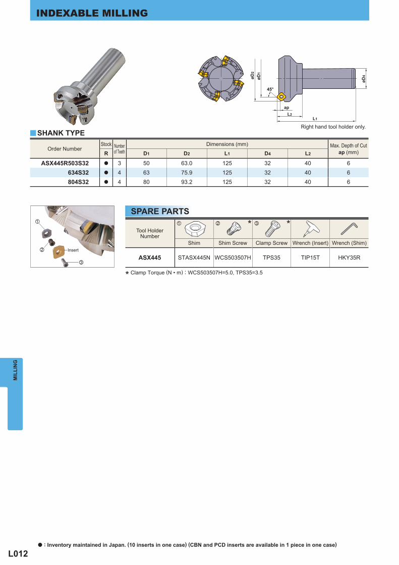
Order Number Stock Number
of Teeth Dimensions (mm) Max. Depth of Cut
ap (mm) R D1 D2 L1 D4 L2
ASX445R503S32 a 3 50 63.0 125 32 40 6634S32 a 4 63 75.9 125 32 40 6804S32 a 4 80 93.2 125 32 40 6
y
Tool HolderNumber
* *
Shim Shim Screw Clamp Screw Wrench (Insert) Wrench (Shim)
ASX445 STASX445N WCS503507H TPS35 TIP15T HKY35R
z x c
x
z
c
øD4
L2L1
øD2
øD1
45°
ap
MIL
LIN
GINDEXABLE MILLING
* Clamp Torque (N • m) : WCS503507H=5.0, TPS35=3.5
SPARE PARTS
SHANK TYPERight hand tool holder only.
Insert
a : Inventory maintained in Japan. (10 inserts in one case) (CBN and PCD inserts are available in 1 piece in one case)
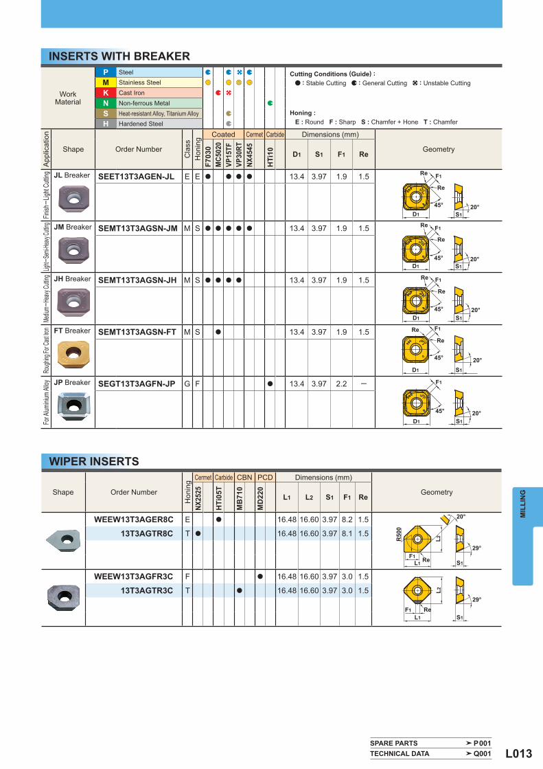
L013
WorkMaterial
P Steel
M Stainless Steel
K Cast Iron
N Non-ferrous Metal
S Heat-resistant Alloy, Titanium Alloy H Hardened Steel
App
licat
ion
Shape Order Number
Cla
ss
Hon
ing
Coated Cermet Carbide Dimensions (mm)
Geometry
F703
0M
C502
0VP
15TF
VP30
RTNX
4545
HTi
10 D1 S1 F1 Re
Finish
─ Ligh
t Cutt
ing
JL Breaker SEET13T3AGEN-JL E E a a a a 13.4 3.97 1.9 1.5
Light─
Semi-
Heavy
Cuttin
g
JM Breaker SEMT13T3AGSN-JM M S a a a a a 13.4 3.97 1.9 1.5
Mediu
m─He
avy Cu
tting
JH Breaker SEMT13T3AGSN-JH M S a a a a 13.4 3.97 1.9 1.5
Roug
hing F
or Ca
st Iron
FT Breaker SEMT13T3AGSN-FT M S a 13.4 3.97 1.9 1.5
For A
lumini
um Al
loy
JP Breaker SEGT13T3AGFN-JP G F a 13.4 3.97 2.2 -
Shape Order Number
Hon
ing
Cermet Carbide CBN PCD Dimensions (mm)
Geometry
NX25
25
HTi
05T
MB
710
MD
220
L1 L2 S1 F1 Re
WEEW13T3AGER8C E a 16.48 16.60 3.97 8.2 1.5
13T3AGTR8C T a 16.48 16.60 3.97 8.1 1.5
WEEW13T3AGFR3C F a 16.48 16.60 3.97 3.0 1.5
13T3AGTR3C T a 16.48 16.60 3.97 3.0 1.5
SPARE PARTS P001 TECHNICAL DATA Q001
D1
45°
Re
F1Re
S120°
F1
F1
Re
45°
Re
D1 S1
S1
20°
F1
D1
45° 20°S1
S120°
D1
F1
45°
Re
Re
D1
45°
Re
Re
20°
20°
L2R50
0
L1F1
S1
29°
Re
S1L1F1
L2
Re29°
MIL
LIN
G
WIPER INSERTS
INSERTS WITH BREAKERCutting Conditions (Guide) : : Stable Cutting : General Cutting : Unstable Cutting
Honing : E : Round F : Sharp S : Chamfer + Hone T : Chamfer
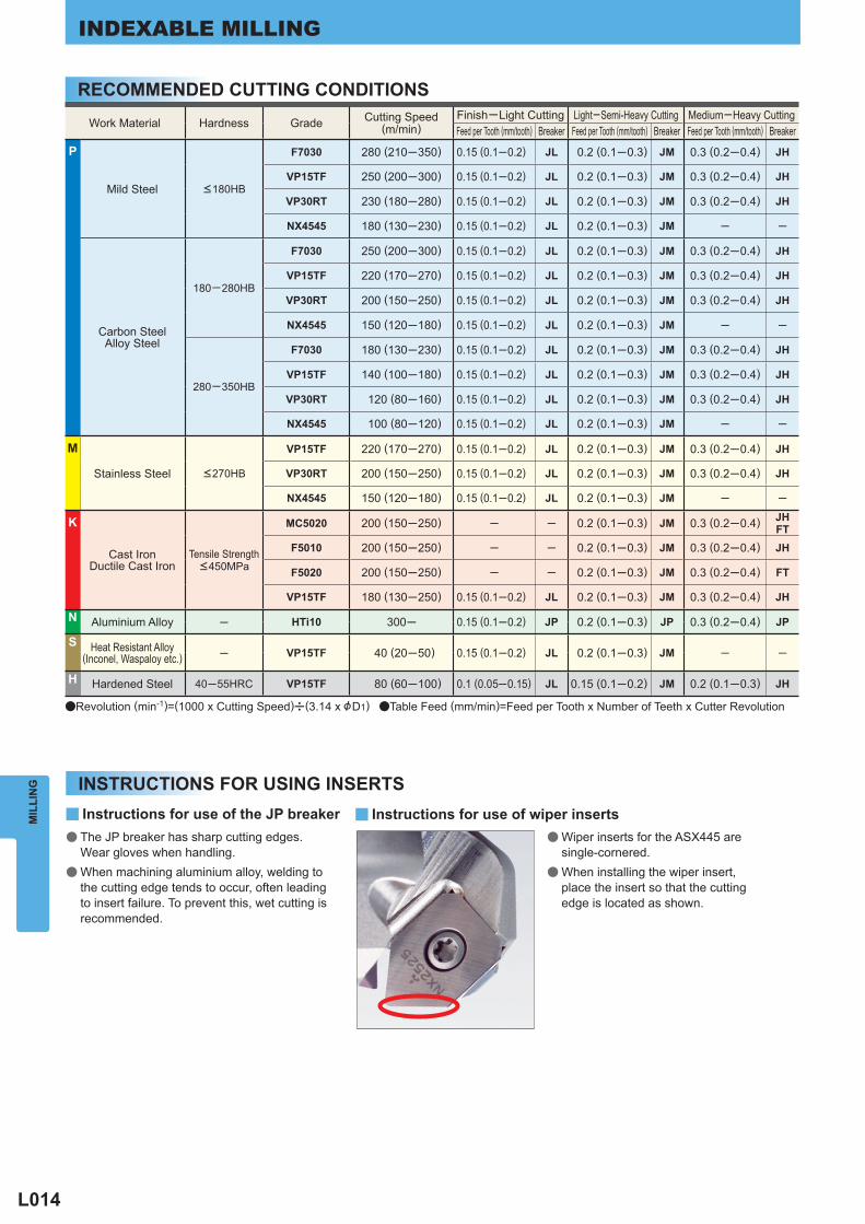
L014
Work Material Hardness Grade Cutting Speed(m/min)
Finish─Light Cutting Light─Semi-Heavy Cutting Medium─Heavy Cutting Feed per Tooth (mm/tooth) Breaker Feed per Tooth (mm/tooth) Breaker Feed per Tooth (mm/tooth) Breaker
P
Mild Steel <180HB
F7030 280 (210─350) 0.15 (0.1─0.2) JL 0.2 (0.1─0.3) JM 0.3 (0.2─0.4) JH
VP15TF 250 (200─300) 0.15 (0.1─0.2) JL 0.2 (0.1─0.3) JM 0.3 (0.2─0.4) JH
VP30RT 230 (180─280) 0.15 (0.1─0.2) JL 0.2 (0.1─0.3) JM 0.3 (0.2─0.4) JH
NX4545 180 (130─230) 0.15 (0.1─0.2) JL 0.2 (0.1─0.3) JM ─ ─
Carbon SteelAlloy Steel
180─280HB
F7030 250 (200─300) 0.15 (0.1─0.2) JL 0.2 (0.1─0.3) JM 0.3 (0.2─0.4) JH
VP15TF 220 (170─270) 0.15 (0.1─0.2) JL 0.2 (0.1─0.3) JM 0.3 (0.2─0.4) JH
VP30RT 200 (150─250) 0.15 (0.1─0.2) JL 0.2 (0.1─0.3) JM 0.3 (0.2─0.4) JH
NX4545 150 (120─180) 0.15 (0.1─0.2) JL 0.2 (0.1─0.3) JM ─ ─
280─350HB
F7030 180 (130─230) 0.15 (0.1─0.2) JL 0.2 (0.1─0.3) JM 0.3 (0.2─0.4) JH
VP15TF 140 (100─180) 0.15 (0.1─0.2) JL 0.2 (0.1─0.3) JM 0.3 (0.2─0.4) JH
VP30RT 120 (80─160) 0.15 (0.1─0.2) JL 0.2 (0.1─0.3) JM 0.3 (0.2─0.4) JH
NX4545 100 (80─120) 0.15 (0.1─0.2) JL 0.2 (0.1─0.3) JM ─ ─
M
Stainless Steel <270HB
VP15TF 220 (170─270) 0.15 (0.1─0.2) JL 0.2 (0.1─0.3) JM 0.3 (0.2─0.4) JH
VP30RT 200 (150─250) 0.15 (0.1─0.2) JL 0.2 (0.1─0.3) JM 0.3 (0.2─0.4) JH
NX4545 150 (120─180) 0.15 (0.1─0.2) JL 0.2 (0.1─0.3) JM ─ ─
K
Cast IronDuctile Cast Iron
Tensile Strength <450MPa
MC5020 200 (150─250) ─ ─ 0.2 (0.1─0.3) JM 0.3 (0.2─0.4) JHFT
F5010 200 (150─250) ─ ─ 0.2 (0.1─0.3) JM 0.3 (0.2─0.4) JH
F5020 200 (150─250) ─ ─ 0.2 (0.1─0.3) JM 0.3 (0.2─0.4) FT
VP15TF 180 (130─250) 0.15 (0.1─0.2) JL 0.2 (0.1─0.3) JM 0.3 (0.2─0.4) JH
N Aluminium Alloy ─ HTi10 300─ 0.15 (0.1─0.2) JP 0.2 (0.1─0.3) JP 0.3 (0.2─0.4) JP
S Heat Resistant Alloy(Inconel, Waspaloy etc.) ─ VP15TF 40 (20─50) 0.15 (0.1─0.2) JL 0.2 (0.1─0.3) JM ─ ─
H Hardened Steel 40─55HRC VP15TF 80 (60─100) 0.1 (0.05─0.15) JL 0.15 (0.1─0.2) JM 0.2 (0.1─0.3) JH
y yMIL
LIN
GINDEXABLE MILLING
RECOMMENDED CUTTING CONDITIONS
INSTRUCTIONS FOR USING INSERTS
aRevolution (min-1)=(1000 x Cutting Speed)u(3.14 x &D1) aTable Feed (mm/min)=Feed per Tooth x Number of Teeth x Cutter Revolution
The JP breaker has sharp cutting edges. Wear gloves when handling.When machining aluminium alloy, welding to the cutting edge tends to occur, often leading to insert failure. To prevent this, wet cutting is recommended.
Wiper inserts for the ASX445 are single-cornered.When installing the wiper insert, place the insert so that the cutting edge is located as shown.
Instructions for use of the JP breaker Instructions for use of wiper inserts●
●
●
●
L015
MIL
LIN
GP M HSNK
y
y
y
a a a
y
HTi10
VP15TF VP15TFVP30RT
VP15TF
F7030F7030
VP30RT
VP15TF
VP15TF
MC5020
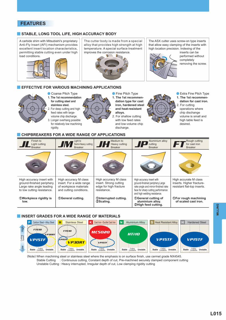
1. The 1st recommen-dation for cast iron.
2. For cutting operations where chip dischange volume is small and high table feed is desired.
1. The 1st recommen-dation type for cast iron, hardened steel and heat-resistant alloys.
2. For shallow cutting with low feed rates and low-volume chip discharge.
Coarse Pitch Type1. The 1st recommendation
for cutting steel and stainless steel.
2. For deep cutting and high feed rates with large-volume chip discharge.
3. Longer overhang possible for relatively low machining rigidity.
The ASX cutter uses screw-on type inserts that allow easy clamping of the inserts with high location precision. Indexing of the
inserts can be performed without completely removing the screw.
A carbide shim with Mitsubishi's proprietary Anti-Fly Insert (AFI) mechanism provides excellent insert location characteristics, permitting stable cutting even under high load conditions.
The cutter body is made from a special alloy that provides high strength at high temperature. A special surface treatment improves the corrosion resistance.
Stainless Steel Aluminium Alloy Heat Resistant Alloy Hardened SteelCarbon Steel • Alloy Steel
High accuracy insert with ground-finished periphery.Large rake angle leading to low cutting resistance.
High accurate M class inserts. Higher fracture-resistant flat-top inserts.
zFor rough machining of scaled cast iron.
zWorkpiece rigidity is low.
High accuracy M class insert. For a wide range of workpiece materials and cutting conditions.
zGeneral cutting.
High accuracy M class insert. Strong cutting edge for high fracture resistance.
zInterrupted cutting.xScaling.
High accuracy insert with ground-finished periphery.Large rake angle and mirror-finished rake face for sharp cutting performance and high welding resistance.zGeneral cutting of aluminium alloy.xHigh feed cutting.
Low
Hig
hC
uttin
gS
peed
(Note) When machining steel or stainless steel where the emphasis is on surface finish, use cermet grade NX4545. Stable Cutting : Continuous cutting, Constant depth of cut, Pre-machined securely clamped component cutting Unstable Cutting : Heavy interrupted, Irregular depth of cut, Low clamping rigidity cutting
FEATURES
STABLE, LONG TOOL LIFE, HIGH ACCURACY BODY
EFFECTIVE FOR VARIOUS MACHINING APPLICATIONS
CHIPBREAKERS FOR A WIDE RANGE OF APPLICATIONS
INSERT GRADES FOR A WIDE RANGE OF MATERIALS
Fine Pitch Type Extra Fine Pitch Type
JL JM FTJPJHRough cutting for cast ironBreaker
Finish to Light cuttingBreaker
Light to Semi-Heavy cuttingBreaker
Medium to Heavy cuttingBreaker
Aluminium alloy cuttingBreaker
Cast Iron • Ductile Cast Iron
UnstableStable CuttingConditions UnstableStable Cutting
ConditionsUnstableStable CuttingConditionsUnstableStable Cutting
Conditions UnstableStable CuttingConditionsUnstableStable Cutting
Conditions
L016
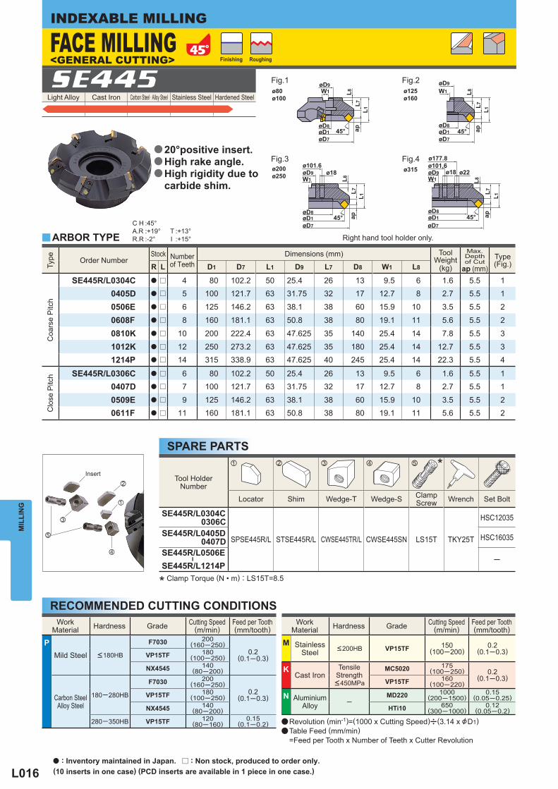
Light Alloy Cast Iron Carbon Steel · Alloy Steel Stainless Steel Hardened Steel SE445
Type
Order Number Stock Number
of Teeth Dimensions (mm) Tool
Weight (kg)
Max. Depthof Cut
ap (mm) Type
(Fig.) R L D1 D7 L1 D9 L7 D8 W1 L8
Coa
rse
Pitc
h
SE445R/L0304C a r 4 80 102.2 50 25.4 26 13 9.5 6 1.6 5.5 10405D a r 5 100 121.7 63 31.75 32 17 12.7 8 2.7 5.5 1
0506E a r 6 125 146.2 63 38.1 38 60 15.9 10 3.5 5.5 2
0608F a r 8 160 181.1 63 50.8 38 80 19.1 11 5.6 5.5 2
0810K a r 10 200 222.4 63 47.625 35 140 25.4 14 7.8 5.5 3
1012K a r 12 250 273.2 63 47.625 35 180 25.4 14 12.7 5.5 31214P a r 14 315 338.9 63 47.625 40 245 25.4 14 22.3 5.5 4
Clo
se P
itch
SE445R/L0306C a r 6 80 102.2 50 25.4 26 13 9.5 6 1.6 5.5 10407D a r 7 100 121.7 63 31.75 32 17 12.7 8 2.7 5.5 1
0509E a r 9 125 146.2 63 38.1 38 60 15.9 10 3.5 5.5 20611F a r 11 160 181.1 63 50.8 38 80 19.1 11 5.6 5.5 2
Tool HolderNumber
*
Locator Shim Wedge-T Wedge-S ClampScrew Wrench Set Bolt
SE445R/L0304C 0306C
SPSE445R/L STSE445R/L CWSE445TR/L CWSE445SN LS15T TKY25T
HSC12035
SE445R/L0405D 0407D HSC16035
SE445R/L0506E
―
SE445R/L1214P─
z x c v b
C H :45°A.R :+19°R.R :-2°
T :+13°I :+15°y
c
v
b
z
x
WorkMaterial Hardness Grade Cutting Speed
(m/min) Feed per Tooth(mm/tooth)
P Mild Steel <180HB
F7030 200(160─250)
0.2(0.1─0.3)VP15TF 180
(100─250)
NX4545 140(80─200)
Carbon SteelAlloy Steel
180─280HB
F7030 200(160─250)
0.2(0.1─0.3)VP15TF 180
(100─250)
NX4545 140(80─200)
280─350HB VP15TF 120(80─160)
0.15(0.1─0.2)
WorkMaterial Hardness Grade Cutting Speed
(m/min) Feed per Tooth(mm/tooth)
M StainlessSteel <200HB VP15TF 150
(100─200)0.2
(0.1─0.3)
K Cast Iron
Tensile Strength <450MPa
MC5020 175(100─250) 0.2
(0.1─0.3)VP15TF 160(100─220)
N AluminiumAlloy ─
MD220 1000(200─1500)
0.15(0.05─0.25)
HTi10 650(300─1000)
0.12(0.05─0.2)
øD7
øD8
øD9W1
45°øD1
L8L7
apL1
ø101.6ø18
øD7
øD9W1 L8
L7L1
45°øD8øD1 ap
øD7
ø177.8ø101.6
ø18øD9W1
ø22
L8
L7L1
45°øD8øD1 ap
øD7
øD9W1 L8
45°øD8øD1
L7ap
L1
ø80ø100
ø200ø250
ø125ø160
ø315
MIL
LIN
GINDEXABLE MILLING
* Clamp Torque (N • m) : LS15T=8.5
SPARE PARTS
RECOMMENDED CUTTING CONDITIONS
ARBOR TYPE
a Revolution (min-1)=(1000 x Cutting Speed)u(3.14 x &D1)a Table Feed (mm/min) =Feed per Tooth x Number of Teeth x Cutter Revolution
FACE MILLING<GENERAL CUTTING>
Fig.1 Fig.2
Fig.3 Fig.4
Finishing Roughing
Insert
Right hand tool holder only.
20°positive insert.High rake angle.High rigidity due to carbide shim.
a
a
a
a : Inventory maintained in Japan. r : Non stock, produced to order only.(10 inserts in one case) (PCD inserts are available in 1 piece in one case.)
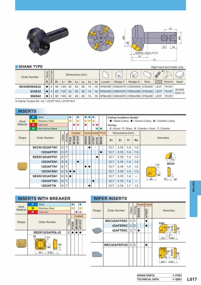
L017
Order Number
Sto
ck
Numb
er of
Teeth
Dimensions (mm) *
R D1 L1 D4 L2 L4 L5 L6 Locator Wedge-T Wedge-S Shim ClampScrew Wrench Insert
SE445R504S32 a 4 50 125 32 45 36 14 19 SPSE445R CWSE445TR CWSE445SN STSE445R LS10T TKY25TSEC/E/KN
1203AFoN1634S32 a 4 63 125 32 45 36 14 19 SPSE445R CWSE445TR CWSE445SN STSE445R LS10T TKY25T
804S42 a 4 80 145 42 45 40 14 19 SPSE445R CWSE445TR CWSE445SN STSE445R LS15T TKY25T
WorkMaterial
P Steel M Stainless Steel K Cast Iron
Shape Order Number
Cla
ss
Coated
F703
0M
C50
20VP
15TF
SEER1203AFEN-JS E a a a
WorkMaterial
P Steel M Stainless Steel
K Cast Iron N Non-ferrous Metal
Shape Order Number
Cla
ss
Hon
ing
Coated Cermet Carbide PCD Dimensions (mm)
Geometry
F703
0M
C502
0VP
15TF
NX25
25NX
4545
UTi2
0TH
Ti10
MD2
20 D1 S1 F1 Re
SECN1203AFTN1 C T a 12.7 3.18 1.4 1.01203AFFR1 C F a 12.7 3.18 1.4 1.0
SEEN1203AFFN1 E F a 12.7 3.18 1.4 1.0
1203AFEN1 E E a 12.7 3.18 1.4 1.0
1203AFTN1 E T a a 12.7 3.18 1.4 1.0
1203AFSN1 E S a a 12.7 3.18 1.4 1.0
SEKN1203AFSN1 K S a 12.7 3.18 1.4 ─
1203AFTN1 K T a 12.7 3.18 1.4 ─1203AFTN K T a 12.7 3.18 1.7 1.0
Shape Order Number
Cla
ss
Hon
ing
Cermet Carbide
Geometry
NX2
525
HTI
05T
WEC42AFFR5C C F a
42AFER5C C E a
42AFTR5C C T a
WEC42AFER10C C E a
y
SPARE PARTS P001 TECHNICAL DATA Q001
ø
L5 L6
L1
5.5L2
L4
øD1
45°
D4
3.18
20°
12.7
18.8
1645°
R1
R1R500
10
12.7
1.4
45°
R1
3.18
20°
S1 20°
F1
D1
45°Re
F1
MD220
20°
3.18
45°
512.7
R500
R1R1
15.3
3
MIL
LIN
G
WIPER INSERTS
(Max. Depth of Cut)
INSERTS
INSERTS WITH BREAKER
SHANK TYPE
* Clamp Torque (N • m) : LS10T=8.5, LS15T=8.5
Right hand tool holder only.
Cutting Conditions (Guide) : : Stable Cutting : General Cutting : Unstable Cutting
Honing : E : Round F : Sharp S : Chamfer + Hone T : Chamfer
L018
Light Alloy Cast Iron Carbon Steel · Alloy Steel Stainless Steel Hardened Steel SE545
Tool HolderNumber
*
Locator Shim Wedge-T Wedge-S ClampScrew Wrench Set Bolt
SE545R0405D
SPSE545R STSE545R CWSE545TR CWSE545SN LS15T TKY25T
HSC16035
SE545R0506E
―
SE545R1012K─
Type
Order Number Stock Number
of Teeth Dimensions (mm) Tool
Weight (kg)
Max. Depthof Cut
ap (mm) Type
(Fig.) R D1 D7 L1 D9 L7 D8 W1 L8
Coa
rse
Pitc
h
SE545R0405D a 5 100 124.9 63 31.75 32 17 12.7 8 2.9 7.5 1
0506E a 6 125 149.8 63 38.1 38 60 15.9 10 3.7 7.5 2
0608F a 8 160 184.7 63 50.8 38 80 19.1 11 5.9 7.5 2
0810K a 10 200 225.7 63 47.625 35 140 25.4 14 8.2 7.5 3
1012K a 12 250 276.3 63 47.625 35 180 25.4 14 13.4 7.5 3
C H :45°A.R :+19°R.R :-2°
T :+13°I :+15°
z x c v b
c
v
b
z
x
WorkMaterial Hardness Grade Cutting Speed
(m/min) Feed per Tooth(mm/tooth)
P Mild Steel <180HB
F7030 200(160─250)
0.2(0.1─0.3)VP15TF 180
(100─250)
NX4545 140(80─200)
Carbon SteelAlloy Steel
180─280HB
F7030 200(160─250)
0.2(0.1─0.3)VP15TF 180
(100─250)
NX4545 140(80─200)
280─350HB VP15TF 120(80─160)
0.15(0.1─0.2)
WorkMaterial Hardness Grade Cutting Speed
(m/min) Feed per Tooth(mm/tooth)
M StainlessSteel <200HB VP15TF 150
(100─200)0.2
(0.1─0.3)
K Cast Iron
Tensile Strength <450MPa
MC5020 175(100─250) 0.2
(0.1─0.3)VP15TF 160(100─220)
N AluminiumAlloy ─
MD220 1000(200─1500)
0.15(0.05─0.25)
HTi10 650(300─1000)
0.12(0.05─0.2)
45°øD7
øD9W1 L8
L7ap
L1
øD8øD1
øD7
øD9W1
apL8
L7 L1
45°øD8øD1
45°øD8øD1
L7ap
L1
ø101.6
øD7
øD9 ø18W1 L8
ø100 ø125ø160
ø200ø250
MIL
LIN
GINDEXABLE MILLING
* Clamp Torque (N • m) : LS15T=8.5
a Revolution (min-1)=(1000 x Cutting Speed)u(3.14 x &D1)a Table Feed (mm/min) =Feed per Tooth x Number of Teeth x Cutter Revolution
SPARE PARTS
RECOMMENDED CUTTING CONDITIONS
Right hand tool holder only.
FACE MILLING<HEAVY CUTTING>
Fig.1 Fig.2
Fig.3
Finishing Roughing
Insert
20°positive insert.High rake angle.High rigidity due to carbide shim.
a
a
a
a : Inventory maintained in Japan. (10 inserts in one case)
L019
WorkMaterial
P Steel M Stainless Steel
K Cast Iron N Non-ferrous Metal
Shape Order Number
Cla
ss
Hon
ing
Coated Cermet Carbide Dimensions (mm)
Geometry
F703
0M
C50
20VP
15TF
NX2
525
NX4
545
UTi
20T
HTi
10 D1 S1 F1 Re
SECN1504AFTN1 C T a 15.875 4.76 1.4 1.0
SEEN1504AFFN1 E F a 15.875 4.76 1.4 1.0
1504AFEN1 E E a 15.875 4.76 1.4 1.0
1504AFTN1 E T a a 15.875 4.76 1.4 1.0
1504AFSN1 E S a a 15.875 4.76 1.4 1.0
SEKN1504AFTN1 K T a 15.875 4.76 1.4 ─
1504AFSN1 K S a 15.875 4.76 1.4 ─
1504AFTN K T a 15.875 4.76 1.7 1.0
WorkMaterial
P Steel M Stainless Steel
K Cast Iron N Non-ferrous Metal
Shape Order Number
Cla
ss
Hon
ing
Coated Dimensions (mm)
Geometry
F703
0M
C50
20 D1 S1 F1 Re
SEER1504AFEN-JS E E a a 15.875 4.76 1.4 1.0
Shape Order Number
Cla
ss
Hon
ing
Cermet Carbide Dimensions (mm)
Geometry
NX2
525
HTi
05T L1 L2 S1 Re
WEC53AFER5C C E a 15.875 18.505 4.76 1.0
53AFTR5C C T a 15.875 18.505 4.76 1.0
SPARE PARTS P001 TECHNICAL DATA Q001
L2
S1
20°
L1
ReRe
R500
5
45°
S1
20°
F1
D1
45°Re
D1
45°
F1Re
S1
20°
MIL
LIN
GWIPER INSERTS
INSERTS WITH BREAKER
INSERTSCutting Conditions (Guide) : : Stable Cutting : General Cutting : Unstable Cutting
Honing : E : Round F : Sharp S : Chamfer + Hone T : Chamfer
Cutting Conditions (Guide) : : Stable Cutting : General Cutting : Unstable Cutting
Honing : E : Round
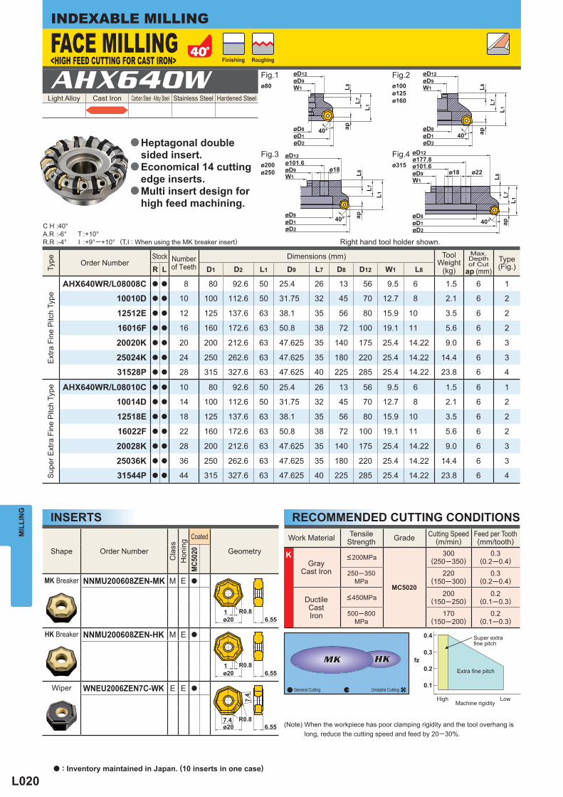
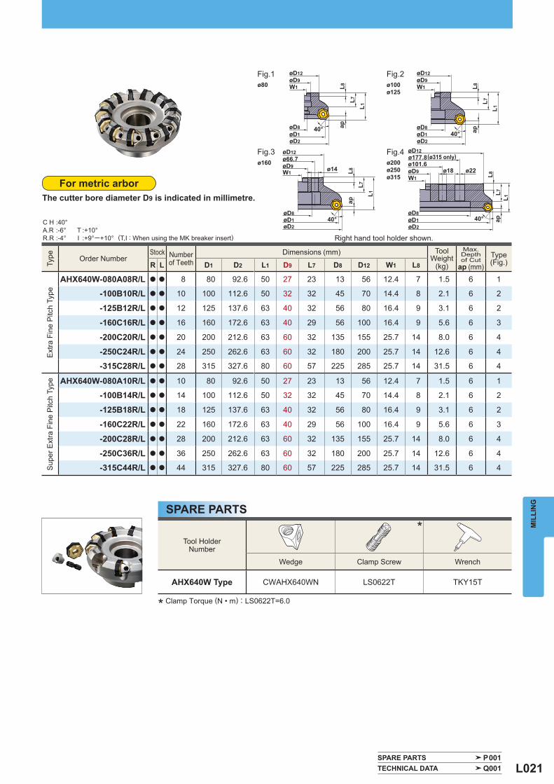
L020
Light Alloy Cast Iron Carbon Steel · Alloy Steel Stainless Steel Hardened Steel AHX640W
Type
Order Number Stock Number
of Teeth Dimensions (mm) Tool
Weight (kg)
Max. Depthof Cut
ap (mm) Type
(Fig.) R L D1 D2 L1 D9 L7 D8 D12 W1 L8
Ext
ra F
ine
Pitc
h Ty
pe
AHX640WR/L08008C a a 8 80 92.6 50 25.4 26 13 56 9.5 6 1.5 6 1
10010D a a 10 100 112.6 50 31.75 32 45 70 12.7 8 2.1 6 2
12512E a a 12 125 137.6 63 38.1 35 56 80 15.9 10 3.5 6 2
16016F a a 16 160 172.6 63 50.8 38 72 100 19.1 11 5.6 6 2
20020K a a 20 200 212.6 63 47.625 35 140 175 25.4 14.22 9.0 6 3
25024K a a 24 250 262.6 63 47.625 35 180 220 25.4 14.22 14.4 6 3
31528P a a 28 315 327.6 63 47.625 40 225 285 25.4 14.22 23.8 6 4
Sup
er E
xtra
Fin
e P
itch
Type
AHX640WR/L08010C a a 10 80 92.6 50 25.4 26 13 56 9.5 6 1.5 6 1
10014D a a 14 100 112.6 50 31.75 32 45 70 12.7 8 2.1 6 2
12518E a a 18 125 137.6 63 38.1 35 56 80 15.9 10 3.5 6 2
16022F a a 22 160 172.6 63 50.8 38 72 100 19.1 11 5.6 6 2
20028K a a 28 200 212.6 63 47.625 35 140 175 25.4 14.22 9.0 6 3
25036K a a 36 250 262.6 63 47.625 35 180 220 25.4 14.22 14.4 6 3
31544P a a 44 315 327.6 63 47.625 40 225 285 25.4 14.22 23.8 6 4
Shape Order Number
Cla
ss
Hon
ing
Coated
Geometry
MC5
020
MK Breaker NNMU200608ZEN-MK M E a
HK Breaker NNMU200608ZEN-HK M E a
Wiper WNEU2006ZEN7C-WK E E a
C H :40°A.R :-6°R.R :-4°
T :+10°I :+9°─+10°
Work Material TensileStrength Grade Cutting Speed
(m/min) Feed per Tooth(mm/tooth)
K Gray
Cast Iron
<200MPa
MC5020
300(250─350)
0.3(0.2─0.4)
250─350MPa
220(150─300)
0.3(0.2─0.4)
DuctileCastIron
<450MPa 200(150─250)
0.2(0.1─0.3)
500─800MPa
170(150─200)
0.2(0.1─0.3)ø20
16.55
R0.8
ø201
6.55R0.8
ø207.4
6.55R0.8
7.4
40°
L7L1
L8ap40°
L7L1
L8ap
40°
L7L1
L8ap
øD8øD1øD2
øD8øD1øD2
ø101.6øD9W1
øD12ø177.8
øD8øD1øD2
øD12øD9W1
W1
øD8øD1øD2
øD12øD9W1
40°
L7L1
L8ap
øD9
øD12ø101.6
ø18 ø22ø18
ø80
ø200ø250
ø100ø125ø160
ø315
MIL
LIN
GINDEXABLE MILLING
(T,I : When using the MK breaker insert)
(Note) When the workpiece has poor clamping rigidity and the tool overhang is long, reduce the cutting speed and feed by 20─30%.
General Cutting Unstable Cutting
High
Extra fi ne pitch
Machine rigidity
Super extra fi ne pitch
Low
RECOMMENDED CUTTING CONDITIONSINSERTS
FACE MILLING<HIGH FEED CUTTING FOR CAST IRON>
Fig.1 Fig.2
Fig.3 Fig.4
Finishing Roughing
Right hand tool holder shown.
Heptagonal doublesided insert.Economical 14 cutting edge inserts.Multi insert design forhigh feed machining.
a
a
a
a : Inventory maintained in Japan. (10 inserts in one case)
L021
Type
Order Number Stock Number
of Teeth Dimensions (mm) Tool
Weight (kg)
Max. Depthof Cut
ap (mm) Type
(Fig.) R L D1 D2 L1 D9 L7 D8 D12 W1 L8
Ext
ra F
ine
Pitc
h Ty
pe
AHX640W-080A08R/L a a 8 80 92.6 50 27 23 13 56 12.4 7 1.5 6 1
-100B10R/L a a 10 100 112.6 50 32 32 45 70 14.4 8 2.1 6 2
-125B12R/L a a 12 125 137.6 63 40 32 56 80 16.4 9 3.1 6 2
-160C16R/L a a 16 160 172.6 63 40 29 56 100 16.4 9 5.6 6 3
-200C20R/L a a 20 200 212.6 63 60 32 135 155 25.7 14 8.0 6 4
-250C24R/L a a 24 250 262.6 63 60 32 180 200 25.7 14 12.6 6 4
-315C28R/L a a 28 315 327.6 80 60 57 225 285 25.7 14 31.5 6 4
Sup
er E
xtra
Fin
e P
itch
Type
AHX640W-080A10R/L a a 10 80 92.6 50 27 23 13 56 12.4 7 1.5 6 1
-100B14R/L a a 14 100 112.6 50 32 32 45 70 14.4 8 2.1 6 2
-125B18R/L a a 18 125 137.6 63 40 32 56 80 16.4 9 3.1 6 2
-160C22R/L a a 22 160 172.6 63 40 29 56 100 16.4 9 5.6 6 3
-200C28R/L a a 28 200 212.6 63 60 32 135 155 25.7 14 8.0 6 4
-250C36R/L a a 36 250 262.6 63 60 32 180 200 25.7 14 12.6 6 4
-315C44R/L a a 44 315 327.6 80 60 57 225 285 25.7 14 31.5 6 4
Tool HolderNumber
*
Wedge Clamp Screw Wrench
AHX640W Type CWAHX640WN LS0622T TKY15T
C H :40°A.R :-6°R.R :-4°
T :+10°I :+9°─+10°
SPARE PARTS P001 TECHNICAL DATA Q001
øD8øD1øD2
40°
L7L1
L8ap
ø22ø18ø14W1øD9
øD12ø66.7
40°
L7L1
L8ap
øD8øD1øD2
ø101.6øD9W1
øD12ø177.8
40°
L7L1
L8ap40°
L7L1
L8apøD8
øD1øD2
øD12øD9W1
øD8øD1øD2
øD12øD9W1ø80
ø160
ø100ø125
ø200ø250ø315
MIL
LIN
G
* Clamp Torque (N • m) : LS0622T=6.0
The cutter bore diameter D9 is indicated in millimetre.
SPARE PARTS
For metric arbor
Fig.1 Fig.2
Fig.3 Fig.4
Right hand tool holder shown. (T,I : When using the MK breaker insert)
(ø315 only)
L022
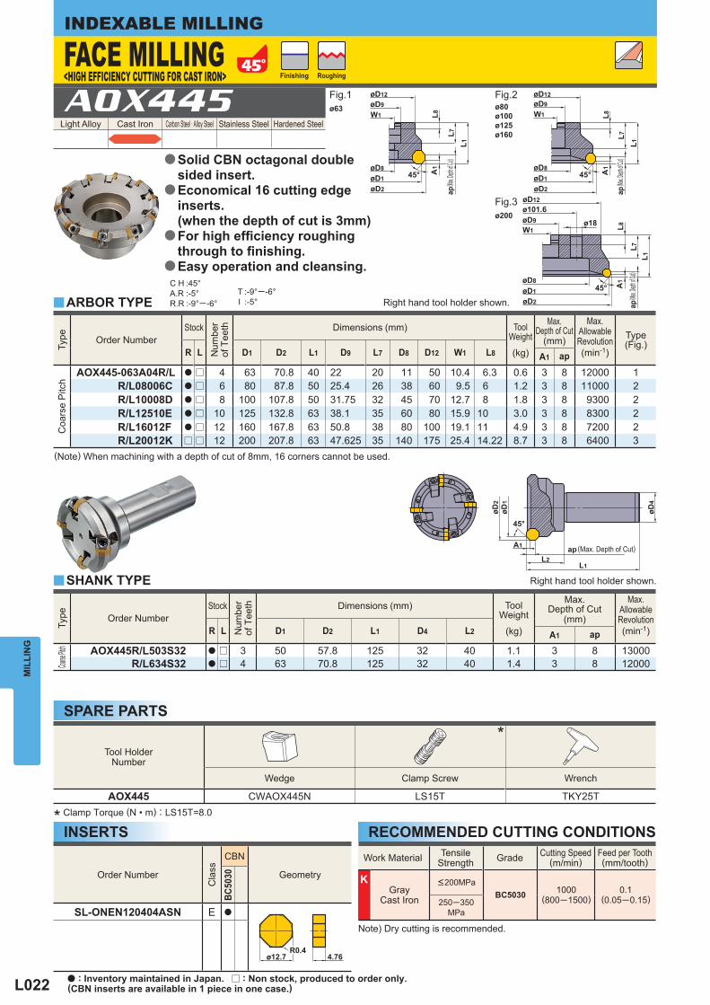
Light Alloy Cast Iron Carbon Steel · Alloy Steel Stainless Steel Hardened Steel AOX445
Type
Order Number Stock
Num
ber
of T
eeth
Dimensions (mm)
ToolWeight
(kg)
Max.
Depth of Cut(mm)
Max.AllowableRevolution(min-1)
R L D1 D2 L1 D4 L2 A1 ap
Coarse
Pitch
AOX445R/L503S32 a r 3 50 57.8 125 32 40 1.1 3 8 13000
R/L634S32 a r 4 63 70.8 125 32 40 1.4 3 8 12000
Work Material TensileStrength Grade Cutting Speed
(m/min) Feed per Tooth(mm/tooth)
K Gray
Cast Iron
<200MPaBC5030 1000
(800─1500)0.1
(0.05─0.15)250─350MPa
Order Number
Cla
ss
CBN
Geometry
BC50
30
SL-ONEN120404ASN E a
Type
Order Number Stock
Num
ber
of T
eeth
Dimensions (mm)
ToolWeight
(kg)
Max.Depth of Cut
(mm)
Max.AllowableRevolution(min-1)
Type(Fig.)
R L D1 D2 L1 D9 L7 D8 D12 W1 L8 A1 ap
Coa
rse
Pitc
h
AOX445-063A04R/L a r 4 63 70.8 40 22 20 11 50 10.4 6.3 0.6 3 8 12000 1R/L08006C a r 6 80 87.8 50 25.4 26 38 60 9.5 6 1.2 3 8 11000 2R/L10008D a r 8 100 107.8 50 31.75 32 45 70 12.7 8 1.8 3 8 9300 2R/L12510E a r 10 125 132.8 63 38.1 35 60 80 15.9 10 3.0 3 8 8300 2R/L16012F a r 12 160 167.8 63 50.8 38 80 100 19.1 11 4.9 3 8 7200 2R/L20012K r r 12 200 207.8 63 47.625 35 140 175 25.4 14.22 8.7 3 8 6400 3
Tool HolderNumber
*
Wedge Clamp Screw Wrench
AOX445 CWAOX445N LS15T TKY25T
C H :45°A.R :-5°R.R :-9°─ -6°
T :-9°─ -6°I :-5°y
y
ø63 ø80ø100ø125ø160
ø200
øD9
MIL
LIN
GINDEXABLE MILLING
INSERTS* Clamp Torque (N • m) : LS15T=8.0
(Note) When machining with a depth of cut of 8mm, 16 corners cannot be used.
Note) Dry cutting is recommended.
SPARE PARTS
RECOMMENDED CUTTING CONDITIONS
ARBOR TYPE
SHANK TYPE
FACE MILLINGFig.1 Fig.2
Fig.3
Finishing Roughing
( Max. D
epth of C
ut)( Ma
x. Depth
of Cut)
Right hand tool holder shown.
Right hand tool holder shown.
Solid CBN octagonal doublesided insert.Economical 16 cutting edgeinserts.(when the depth of cut is 3mm)For high effi ciency roughingthrough to fi nishing. Easy operation and cleansing.
a
a
a
a
( Max. D
epth of C
ut)
<HIGH EFFICIENCY CUTTING FOR CAST IRON>
a : Inventory maintained in Japan. r : Non stock, produced to order only.(CBN inserts are available in 1 piece in one case.)
(Max. Depth of Cut)
L023
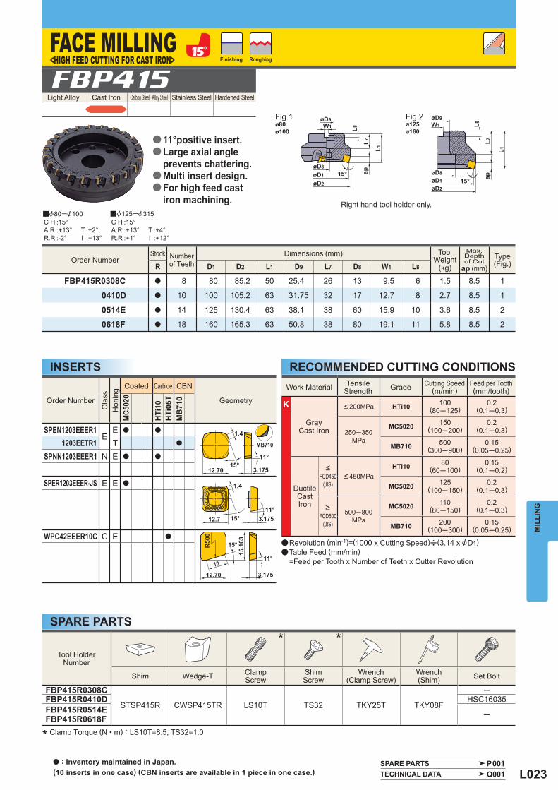
Light Alloy Cast Iron Carbon Steel · Alloy Steel Stainless Steel Hardened Steel FBP415
y&80─&100 y&125─&315
Order Number
Cla
ss
Hon
ing
Coated Carbide CBN
Geometry
MC5
020
HTi
10H
Ti05
TM
B71
0
SPEN1203EEER1E
E a a
1203EETR1 T a
SPNN1203EEER1 N E a a
SPER1203EEER-JS E E a
WPC42EEER10C C E a
Work Material TensileStrength Grade Cutting Speed
(m/min) Feed per Tooth(mm/tooth)
K
GrayCast Iron
<200MPa HTi10 100(80─125)
0.2(0.1─0.3)
250─350MPa
MC5020 150(100─200)
0.2(0.1─0.3)
MB710 500(300─900)
0.15(0.05─0.25)
DuctileCastIron
<
FCD450(JIS)
<450MPaHTi10 80
(60─100)0.15
(0.1─0.2)
MC5020 125(100─150)
0.2(0.1─0.3)
>
FCD500(JIS)
500─800MPa
MC5020 110(80─150)
0.2(0.1─0.3)
MB710 200(100─300)
0.15(0.05─0.25)
Order Number Stock Number
of Teeth Dimensions (mm) Tool
Weight (kg)
Max. Depthof Cut
ap (mm) Type
(Fig.) R D1 D2 L1 D9 L7 D8 W1 L8
FBP415R0308C a 8 80 85.2 50 25.4 26 13 9.5 6 1.5 8.5 1
0410D a 10 100 105.2 63 31.75 32 17 12.7 8 2.7 8.5 1
0514E a 14 125 130.4 63 38.1 38 60 15.9 10 3.6 8.5 2
0618F a 18 160 165.3 63 50.8 38 80 19.1 11 5.8 8.5 2
Tool HolderNumber
* *
Shim Wedge-T ClampScrew
ShimScrew
Wrench(Clamp Screw)
Wrench(Shim) Set Bolt
FBP415R0308C
STSP415R CWSP415TR LS10T TS32 TKY25T TKY08F
─FBP415R0410D HSC16035FBP415R0514EFBP415R0618F ─
C H :15°A.R :+13°R.R :-2°
C H :15°A.R :+13°R.R :+1°
T :+2°I :+13°
T :+4°I :+12°
SPARE PARTS P001 TECHNICAL DATA Q001
ø80ø100
ø125ø160
MIL
LIN
G
* Clamp Torque (N • m) : LS10T=8.5, TS32=1.0
SPARE PARTS
RECOMMENDED CUTTING CONDITIONSINSERTS
Right hand tool holder only.
a Revolution (min-1)=(1000 x Cutting Speed)u(3.14 x &D1)a Table Feed (mm/min) =Feed per Tooth x Number of Teeth x Cutter Revolution
Fig.1 Fig.2
Finishing Roughing
11°positive insert.Large axial angle prevents chattering.Multi insert design.For high feed cast iron machining.
a
a
a
a
a : Inventory maintained in Japan. (10 inserts in one case) (CBN inserts are available in 1 piece in one case.)
FACE MILLING<HIGH FEED CUTTING FOR CAST IRON>
L024
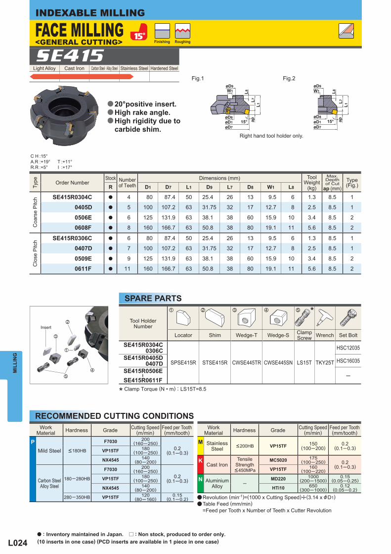
Light Alloy Cast Iron Carbon Steel · Alloy Steel Stainless Steel Hardened Steel SE415
Type
Order Number Stock Number
of Teeth Dimensions (mm) Tool
Weight (kg)
Max. Depthof Cut
ap (mm) Type
(Fig.) R D1 D7 L1 D9 L7 D8 W1 L8
Coa
rse
Pitc
h
SE415R0304C a 4 80 87.4 50 25.4 26 13 9.5 6 1.3 8.5 1
0405D a 5 100 107.2 63 31.75 32 17 12.7 8 2.5 8.5 1
0506E a 6 125 131.9 63 38.1 38 60 15.9 10 3.4 8.5 2
0608F a 8 160 166.7 63 50.8 38 80 19.1 11 5.6 8.5 2
Clo
se P
itch
SE415R0306C a 6 80 87.4 50 25.4 26 13 9.5 6 1.3 8.5 1
0407D a 7 100 107.2 63 31.75 32 17 12.7 8 2.5 8.5 1
0509E a 9 125 131.9 63 38.1 38 60 15.9 10 3.4 8.5 2
0611F a 11 160 166.7 63 50.8 38 80 19.1 11 5.6 8.5 2
C H :15°A.R :+19°R.R :+5°
T :+11°I :+17°
Tool HolderNumber
*
Locator Shim Wedge-T Wedge-S ClampScrew Wrench Set Bolt
SE415R0304C 0306C
SPSE415R STSE415R CWSE445TR CWSE445SN LS15T TKY25T
HSC12035
SE415R0405D 0407D HSC16035
SE415R0506E
―
SE415R0611F─
z x c v b
c
v
b
z
x
WorkMaterial Hardness Grade Cutting Speed
(m/min) Feed per Tooth(mm/tooth)
P Mild Steel <180HB
F7030 200(160─250)
0.2(0.1─0.3)VP15TF 180
(100─250)
NX4545 140(80─200)
Carbon SteelAlloy Steel
180─280HB
F7030 200(160─250)
0.2(0.1─0.3)VP15TF 180
(100─250)
NX4545 140(80─200)
280─350HB VP15TF 120(80─160)
0.15(0.1─0.2)
WorkMaterial Hardness Grade Cutting Speed
(m/min) Feed per Tooth(mm/tooth)
M StainlessSteel <200HB VP15TF 150
(100─200)0.2
(0.1─0.3)
K Cast Iron
Tensile Strength <450MPa
MC5020 175(100─250) 0.2
(0.1─0.3)VP15TF 160(100─220)
N AluminiumAlloy ─
MD220 1000(200─1500)
0.15(0.05─0.25)
HTi10 650(300─1000)
0.12(0.05─0.2)
øD7
øD9W1 L8
L7ap
L1
15°øD8øD1
øD9W1 L8
L7ap
L1
15°øD8øD1øD7
MIL
LIN
GINDEXABLE MILLING
* Clamp Torque (N • m) : LS15T=8.5
SPARE PARTS
RECOMMENDED CUTTING CONDITIONS
Right hand tool holder only.
FACE MILLING<GENERAL CUTTING>
Fig.1 Fig.2
Finishing Roughing
Insert
20°positive insert.High rake angle.High rigidity due to carbide shim.
a
a
a
a : Inventory maintained in Japan. r : Non stock, produced to order only.(10 inserts in one case) (PCD inserts are available in 1 piece in one case)
a Revolution (min-1)=(1000 x Cutting Speed)u(3.14 x &D1)a Table Feed (mm/min) =Feed per Tooth x Number of Teeth x Cutter Revolution
L025
WorkMaterial
P Steel M Stainless Steel K Cast Iron
Shape Order Number
Cla
ss
Hon
ing
Coated Dimensions (mm)
Geometry
F703
0M
C50
20
D1 S1 F1 Re
SEER1203EFER-JS E E a a 12.7 3.18 1.4 1.0
Shape Order Number
Cla
ss
Hon
ing
Cermet Carbide Dimensions (mm)
Geometry
NX2
525
HTi
05T
L1 L2 S1 F1 Re
WEC42EFFR5C C F r 12.7 13.728 3.18 5 1.0
42EFER5C C E a 12.7 13.728 3.18 5 1.0
42EFTR5C C T a 12.7 13.728 3.18 5 1.0
WEC42EFFR10C C F r 12.7 14.99 3.18 10 1.0
42EFER10C C E a 12.7 14.99 3.18 10 1.0
WorkMaterial
P Steel
M Stainless Steel
K Cast Iron N Non-ferrous Metal
Shape Order Number
Cla
ss
Hon
ing
Coated Cermet Carbide PCD Dimensions (mm)
Geometry
F703
0M
C50
20VP
15TF
NX2
525
NX4
545
UTi
20T
HTi
10M
D22
0
D1 S1 F1 Re
SECN1203EFFR1 C F a 12.7 3.18 1.4 1.0
1203EFTR1 C T a 12.7 3.18 1.4 1.0
SEEN1203EFFR1 E F a 12.7 3.18 1.4 1.0
1203EFER1 E E a 12.7 3.18 1.4 1.0
1203EFTR1 E T a a 12.7 3.18 1.4 1.0
1203EFSR1 E S a a 12.7 3.18 1.4 1.0
SEKN1203EFTR1 K T a 12.7 3.18 1.4 ─
1203EFSR1 K S a 12.7 3.18 1.4 ─
1203EFTR K T a 12.7 3.18 1.8 1.0
SPARE PARTS P001 TECHNICAL DATA Q001
MD220
S120°
F1
D115°
Re
F1
15°
F1
D1
Re
S1
20°L2
S1
20°
L1
Re
R500
F1
15°Re
L2
20°
L1
Re
R500
F115°
Re
S1
MIL
LIN
GWIPER INSERTS
INSERTS WITH BREAKER
INSERTSCutting Conditions (Guide) : : Stable Cutting : General Cutting : Unstable Cutting
Honing : E : Round F : Sharp S : Chamfer + Hone T : Chamfer
Cutting Conditions (Guide) : : Stable Cutting : General Cutting : Unstable Cutting
Honing : E : Round
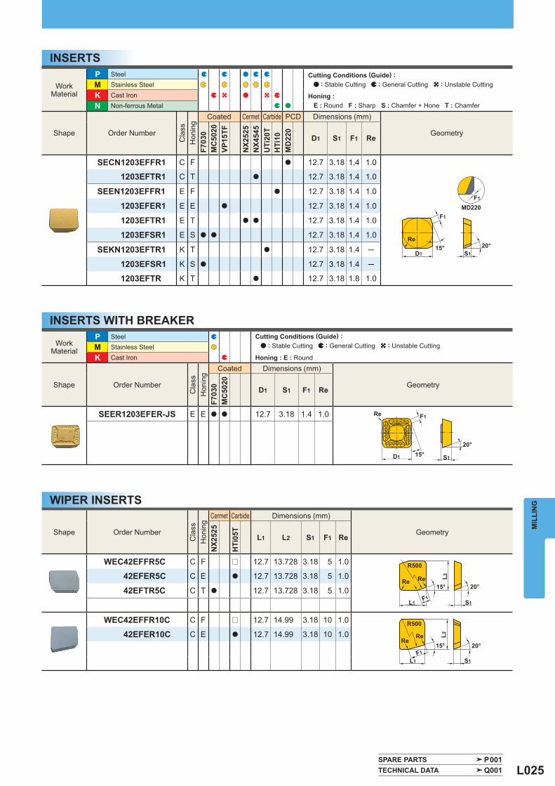
L026
Light Alloy Cast Iron Carbon Steel · Alloy Steel Stainless Steel Hardened Steel SE515
Type
Order Number Stock Number
of Teeth Dimensions (mm) Tool
Weight (kg)
Max. Depthof Cut
ap (mm) Type
(Fig.) R D1 D7 L1 D9 L7 D8 W1 L8
Coar
se P
itch
SE515R0405D [ 5 100 108.9 63 31.75 32 17 12.7 8 2.3 11.5 1
0506E [ 6 125 133.6 63 38.1 38 60 15.9 10 3.5 11.5 2
0608F [ 8 160 168.3 63 50.8 38 60 19.1 11 5.6 11.5 2
Clo
se P
itch
SE515R0407D [ 7 100 108.9 63 31.75 32 17 12.7 8 2.3 11.5 1
0509E [ 9 125 133.6 63 38.1 38 60 15.9 10 3.5 11.5 2
0611F [ 11 160 168.3 63 50.8 38 60 19.1 11 5.6 11.5 2
C H :15°A.R :+19°R.R :+5°
T :+11°I :+17°
Tool HolderNumber
*
Locator Shim Wedge-T Wedge-S ClampScrew Wrench Set Bolt
SE515R0405D 0407D
SPSE515R STSE515R CWSE545TR CWSE545SN LS15T TKY25THSC16035
SE515R0506E
―
SE515R0611F─
z x c v b
c
v
b
z
x
WorkMaterial Hardness Grade Cutting Speed
(m/min) Feed per Tooth(mm/tooth)
P Mild Steel <180HB
F7030 200(160─250)
0.2(0.1─0.3)VP15TF 180
(100─250)
NX4545 140(80─200)
Carbon SteelAlloy Steel
180─280HB
F7030 200(160─250)
0.2(0.1─0.3)VP15TF 180
(100─250)
NX4545 140(80─200)
280─350HB VP15TF 120(80─160)
0.15(0.1─0.2)
WorkMaterial Hardness Grade Cutting Speed
(m/min) Feed per Tooth(mm/tooth)
M StainlessSteel <200HB VP15TF 150
(100─200)0.2
(0.1─0.3)
K Cast Iron
Tensile Strength <450MPa
MC5020 175(100─250) 0.2
(0.1─0.3)VP15TF 160(100─220)
N AluminiumAlloy ─
MD220 1000(200─1500)
0.15(0.05─0.25)
HTi10 650(300─1000)
0.12(0.05─0.2)
øD9W1 L8
L7L1
15°øD8øD1øD7
ap
øD9W1 L8
L7ap
L1
15°øD8øD1øD7
ø100 ø125ø160
MIL
LIN
GINDEXABLE MILLING
* Clamp Torque (N • m) : LS15T=8.5
SPARE PARTS
RECOMMENDED CUTTING CONDITIONS
Right hand tool holder only.
a Revolution (min-1)=(1000 x Cutting Speed)u(3.14 x &D1)a Table Feed (mm/min) =Feed per Tooth x Number of Teeth x Cutter Revolution
FACE MILLING<HEAVY CUTTING>
Fig.1 Fig.2
Finishing Roughing
Insert
20°positive insert.High rake angle.High rigidity due to carbide shim.
a
a
a
a : Inventory maintained in Japan. [ : Inventory maintained in Japan. To be replaced by new products. (10 inserts in one case)
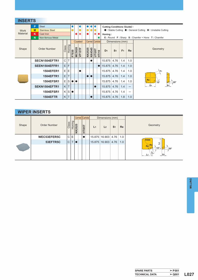
L027
WorkMaterial
P Steel M Stainless Steel
K Cast Iron N Non-ferrous Metal
Shape Order Number
Cla
ss
Hon
ing
Coated Cermet Carbide Dimensions (mm)
Geometry
F703
0M
C50
20VP
15TF
NX2
525
NX4
545
UTi
20T
HTi
10 D1 S1 F1 Re
SECN1504EFTR1 C T a 15.875 4.76 1.4 1.0
SEEN1504EFFR1 E F a 15.875 4.76 1.4 1.0
1504EFER1 E E a 15.875 4.76 1.4 1.0
1504EFTR1 E T a a 15.875 4.76 1.4 1.0
1504EFSR1 E S a a 15.875 4.76 1.4 1.0
SEKN1504EFTR1 K T a 15.875 4.76 1.4 ─
1504EFSR1 K S a 15.875 4.76 1.4 ─
1504EFTR K T a 15.875 4.76 1.8 1.0
Shape Order Number
Cla
ss
Hon
ing
Cermet Carbide Dimensions (mm)
Geometry
NX2
525
HTi
05T L1 L2 S1 Re
WEC53EFER5C C E a 15.875 16.903 4.76 1.0
53EFTR5C C T a 15.875 16.903 4.76 1.0
SPARE PARTS P001 TECHNICAL DATA Q001
20°
L2
S1L1
Re
R500
5
15°Re
20°S1
F1
D1
15°Re
MIL
LIN
G
WIPER INSERTS
INSERTSCutting Conditions (Guide) : : Stable Cutting : General Cutting : Unstable Cutting
Honing : E : Round F : Sharp S : Chamfer + Hone T : Chamfer
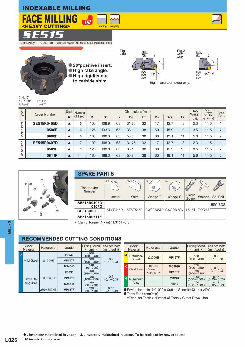
L028
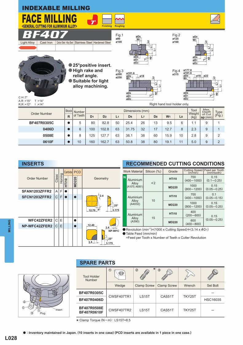
Light Alloy Cast Iron Carbon Steel · Alloy Steel Stainless Steel Hardened Steel BF407
Work Material Silicon (%) Grade Cutting Speed(m/min)
Feed per Tooth(mm/tooth)
N Aluminium
Alloy(A1070, A6061)
<2HTi10 700
(400─1000)0.15
(0.1─0.25)
MD220 1000(800─1200)
0.15(0.05─0.25)
AluminiumAlloy
(A4032) 10
HTi10 700(400─1000)
0.1(0.05─0.15)
MD220 1000(800─1200)
0.15(0.05─0.25)
AluminiumAlloy
(A390) 15
HTi10 400(200─600) 0.15
(0.05─0.25)MD220 600
(400─800)
Order Number Stock Number
of Teeth Dimensions (mm) Tool
Weight (kg)
Max. Depthof Cut
ap (mm) Type
(Fig.) R D1 D2 L1 D9 L7 D8 W1 L8
BF407R0305C a 5 80 82.8 50 25.4 26 13 9.5 6 1.1 9 1
0406D a 6 100 102.8 63 31.75 32 17 12.7 8 2.3 9 1
0508E a 8 125 127.7 63 38.1 38 60 15.9 10 2.8 9 2
0610F a 10 160 162.7 63 50.8 38 80 19.1 11 5.0 9 2
Tool HolderNumber
*
Wedge Clamp Screw Clamp Screw Wrench Set Bolt
BF407R0305CCWSF407TR1 LS15T CAS51T TKY25T
─
BF407R0406D HSC16035
BF407R0508EBF407R0610F CWSF407TR2 LS15T CAS51T TKY25T ─
Order Number
Cla
ss
Hon
ing
Carbide PCD
Geometry
HTi
10
MD
220
SFAN1203ZFFR2 A F a
SFCN1203ZFFR2 C F a a
WFC42ZFER2 C E a
NP-WFC42ZFER2 C E a
C H :7°A.R :+15°R.R :+12°
T :+14°I :+14°
z x c
ø315ø200ø250
ø80ø100
ø125ø160
MIL
LIN
GINDEXABLE MILLING
* Clamp Torque (N • m) : LS15T=8.5
SPARE PARTS
RECOMMENDED CUTTING CONDITIONSINSERTS
Right hand tool holder only.
a Revolution (min-1)=(1000 x Cutting Speed)u(3.14 x &D1)a Table Feed (mm/min) =Feed per Tooth x Number of Teeth x Cutter Revolution
FACE MILLING<GENERAL CUTTING FOR ALUMINIUM ALLOY>
Fig.1 Fig.2
Fig.3 Fig.4
Finishing Roughing
InsertPlug
25°positive insert.High rake andrelief angle.Suitable for light alloy machining.
a
a
a
a : Inventory maintained in Japan. (10 inserts in one case) (PCD inserts are available in 1 piece in one case.)
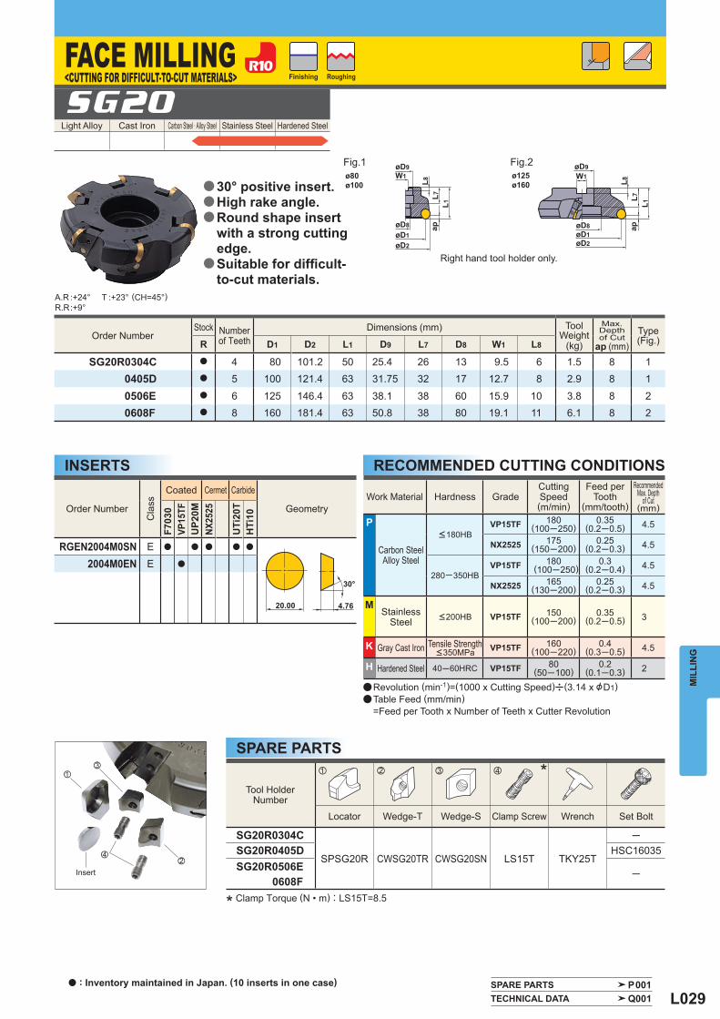
L029
Light Alloy Cast Iron Carbon Steel · Alloy Steel Stainless Steel Hardened Steel SG20
Order Number Stock Number
of Teeth Dimensions (mm) Tool
Weight (kg)
Max. Depthof Cut
ap (mm) Type
(Fig.) R D1 D2 L1 D9 L7 D8 W1 L8
SG20R0304C a 4 80 101.2 50 25.4 26 13 9.5 6 1.5 8 10405D a 5 100 121.4 63 31.75 32 17 12.7 8 2.9 8 1
0506E a 6 125 146.4 63 38.1 38 60 15.9 10 3.8 8 20608F a 8 160 181.4 63 50.8 38 80 19.1 11 6.1 8 2
Tool HolderNumber
*
Locator Wedge-T Wedge-S Clamp Screw Wrench Set Bolt
SG20R0304C
SPSG20R CWSG20TR CWSG20SN LS15T TKY25T
─SG20R0405D HSC16035SG20R0506E
0608F─
Work Material Hardness Grade Cutting Speed(m/min)
Feed per Tooth
(mm/tooth)
RecommendedMax. Depth
of Cut(mm)
P
Carbon SteelAlloy Steel
<180HBVP15TF 180
(100─250)0.35
(0.2─0.5) 4.5
NX2525 175(150─200)
0.25(0.2─0.3) 4.5
280─350HB VP15TF 180
(100─250)0.3
(0.2─0.4) 4.5
NX2525 165(130─200)
0.25(0.2─0.3) 4.5
M Stainless
Steel <200HB VP15TF 150(100─200)
0.35(0.2─0.5) 3
K Gray Cast Iron Tensile Strength <350MPa VP15TF 160
(100─220)0.4
(0.3─0.5) 4.5
H Hardened Steel 40─60HRC VP15TF 80(50─100)
0.2(0.1─0.3) 2
Order Number
Cla
ss
Coated Cermet Carbide
Geometry
F703
0VP
15TF
UP2
0MNX
2525
UTi
20T
HTi
10
RGEN2004M0SN E a a a a a
2004M0EN E a
A.R :+24°R.R :+9°
T :+23°
z x c v
SPARE PARTS P001 TECHNICAL DATA Q001
ø80ø100
ø125ø160
MIL
LIN
G
(CH=45°)
* Clamp Torque (N • m) : LS15T=8.5
SPARE PARTS
RECOMMENDED CUTTING CONDITIONSINSERTS
Right hand tool holder only.
a Revolution (min-1)=(1000 x Cutting Speed)u(3.14 x &D1)a Table Feed (mm/min) =Feed per Tooth x Number of Teeth x Cutter Revolution
FACE MILLING<CUTTING FOR DIFFICULT-TO-CUT MATERIALS>
Fig.1 Fig.2
Finishing Roughing
Insert
30° positive insert.High rake angle.Round shape insertwith a strong cuttingedge.Suitable for diffi cult-to-cut materials.
a
a
a
a
a : Inventory maintained in Japan. (10 inserts in one case)
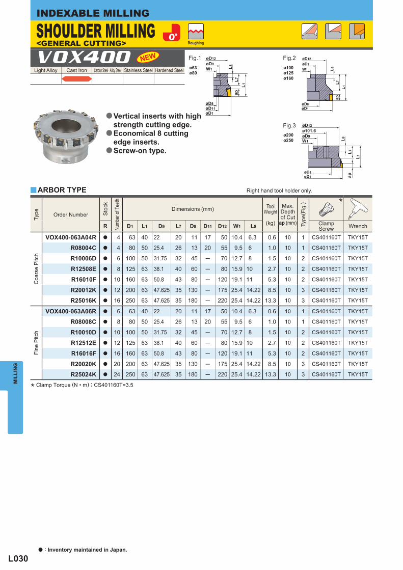
L030
Light Alloy Cast Iron Carbon Steel · Alloy Steel Stainless Steel Hardened Steel VOX400
y
Type
Order Number
Sto
ck
Numb
er of
Tee
th
Dimensions (mm) ToolWeight
(kg)
Max. Depthof Cut
ap (mm)
Type
( Fig
.)
*
R D1 L1 D9 L7 D8 D11 D12 W1 L8 Clamp Screw Wrench
Coa
rse
Pitc
h
VOX400-063A04R a 4 63 40 22 20 11 17 50 10.4 6.3 0.6 10 1 CS401160T TKY15T
R08004C a 4 80 50 25.4 26 13 20 55 9.5 6 1.0 10 1 CS401160T TKY15T
R10006D a 6 100 50 31.75 32 45 ─ 70 12.7 8 1.5 10 2 CS401160T TKY15T
R12508E a 8 125 63 38.1 40 60 ─ 80 15.9 10 2.7 10 2 CS401160T TKY15T
R16010F a 10 160 63 50.8 43 80 ─ 120 19.1 11 5.3 10 2 CS401160T TKY15T
R20012K a 12 200 63 47.625 35 130 ─ 175 25.4 14.22 8.5 10 3 CS401160T TKY15T
R25016K a 16 250 63 47.625 35 180 ─ 220 25.4 14.22 13.3 10 3 CS401160T TKY15T
Fine
Pitc
h
VOX400-063A06R a 6 63 40 22 20 11 17 50 10.4 6.3 0.6 10 1 CS401160T TKY15T
R08008C a 8 80 50 25.4 26 13 20 55 9.5 6 1.0 10 1 CS401160T TKY15T
R10010D a 10 100 50 31.75 32 45 ─ 70 12.7 8 1.5 10 2 CS401160T TKY15T
R12512E a 12 125 63 38.1 40 60 ─ 80 15.9 10 2.7 10 2 CS401160T TKY15T
R16016F a 16 160 63 50.8 43 80 ─ 120 19.1 11 5.3 10 2 CS401160T TKY15T
R20020K a 20 200 63 47.625 35 130 ─ 175 25.4 14.22 8.5 10 3 CS401160T TKY15T
R25024K a 24 250 63 47.625 35 180 ─ 220 25.4 14.22 13.3 10 3 CS401160T TKY15T
W1 L8
øD8øD11øD1
øD9øD12
L7L1
ap
øD1øD8
W1øD9øD12
L8L7
L1ap
øD1øD8
W1øD9ø101.6øD12
L8L7
L1
ap
ø200ø250
ø63ø80
ø100ø125ø160
MIL
LIN
GINDEXABLE MILLING
* Clamp Torque (N • m) : CS401160T=3.5
Vertical inserts with high strength cutting edge.Economical 8 cutting edge inserts.Screw-on type.
a
a
a
ARBOR TYPE Right hand tool holder only.
SHOULDER MILLING<GENERAL CUTTING>
Fig.1 Fig.2
Fig.3
Roughing
a : Inventory maintained in Japan.
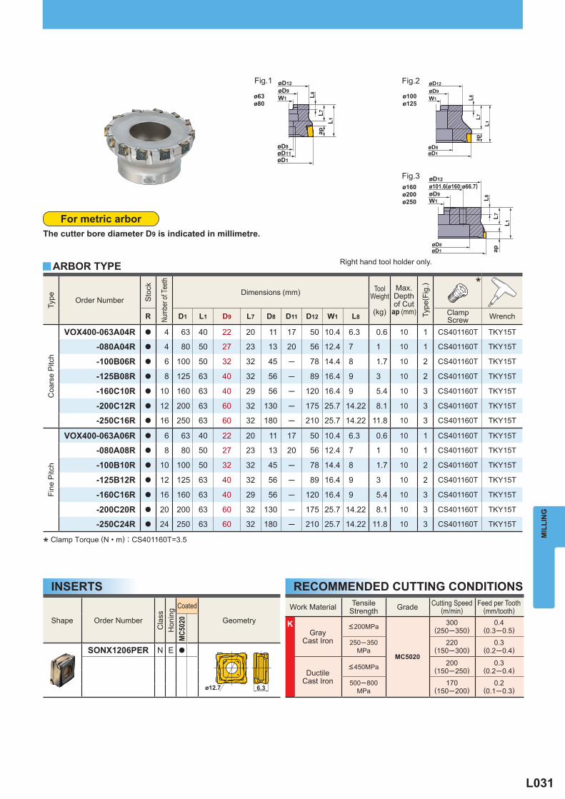
L031
y
Type
Order Number
Sto
ck
Numb
er of
Tee
th
Dimensions (mm) ToolWeight
(kg)
Max. Depthof Cut
ap (mm)
Type
( Fig
.)
*
R D1 L1 D9 L7 D8 D11 D12 W1 L8 Clamp Screw Wrench
Coa
rse
Pitc
h
VOX400-063A04R a 4 63 40 22 20 11 17 50 10.4 6.3 0.6 10 1 CS401160T TKY15T
-080A04R a 4 80 50 27 23 13 20 56 12.4 7 1 10 1 CS401160T TKY15T
-100B06R a 6 100 50 32 32 45 ─ 78 14.4 8 1.7 10 2 CS401160T TKY15T
-125B08R a 8 125 63 40 32 56 ─ 89 16.4 9 3 10 2 CS401160T TKY15T
-160C10R a 10 160 63 40 29 56 ─ 120 16.4 9 5.4 10 3 CS401160T TKY15T
-200C12R a 12 200 63 60 32 130 ─ 175 25.7 14.22 8.1 10 3 CS401160T TKY15T
-250C16R a 16 250 63 60 32 180 ─ 210 25.7 14.22 11.8 10 3 CS401160T TKY15T
Fine
Pitc
h
VOX400-063A06R a 6 63 40 22 20 11 17 50 10.4 6.3 0.6 10 1 CS401160T TKY15T
-080A08R a 8 80 50 27 23 13 20 56 12.4 7 1 10 1 CS401160T TKY15T
-100B10R a 10 100 50 32 32 45 ─ 78 14.4 8 1.7 10 2 CS401160T TKY15T
-125B12R a 12 125 63 40 32 56 ─ 89 16.4 9 3 10 2 CS401160T TKY15T
-160C16R a 16 160 63 40 29 56 ─ 120 16.4 9 5.4 10 3 CS401160T TKY15T
-200C20R a 20 200 63 60 32 130 ─ 175 25.7 14.22 8.1 10 3 CS401160T TKY15T
-250C24R a 24 250 63 60 32 180 ─ 210 25.7 14.22 11.8 10 3 CS401160T TKY15T
Work Material Tensile Strength Grade Cutting Speed
(m/min) Feed per Tooth
(mm/tooth)
K Gray
Cast Iron
<200MPa
MC5020
300(250─350)
0.4(0.3─0.5)
250─350MPa
220(150─300)
0.3(0.2─0.4)
DuctileCast Iron
<450MPa 200(150─250)
0.3(0.2─0.4)
500─800MPa
170(150─200)
0.2(0.1─0.3)
Shape Order Number
Cla
ss
Hon
ing
Coated
Geometry
MC5
020
SONX1206PER N E a
W1 L8
øD8øD11øD1
øD9øD12
L7L1
ap
øD1øD8
W1øD9øD12
L8L7
L1ap
øD1øD8
W1øD9ø101.6(ø160:ø66.7)øD12
L8L7
L1
ap
ø160ø200ø250
ø63ø80
ø100ø125
ø12.7 6.3
MIL
LIN
G* Clamp Torque (N • m) : CS401160T=3.5
ARBOR TYPE Right hand tool holder only.
Fig.1 Fig.2
Fig.3
For metric arborThe cutter bore diameter D9 is indicated in millimetre.
INSERTS RECOMMENDED CUTTING CONDITIONS
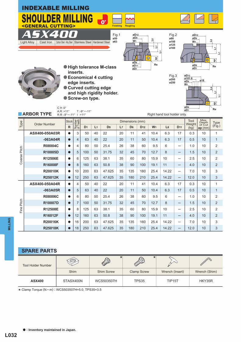
L032
Light Alloy Cast Iron Carbon Steel · Alloy Steel Stainless Steel Hardened Steel ASX400
Tool Holder Number
* *
Shim Shim Screw Clamp Screw Wrench (Insert) Wrench (Shim)
ASX400 STASX400N WCS503507H TPS35 TIP15T HKY35R
Type
Order Number Stock
Num
ber
of T
eeth
Dimensions (mm) ToolWeight
(kg)
Max. Depthof Cut
ap (mm) Type
(Fig.) R D1 L1 D9 L7 D8 D12 W1 L8 D11
Coa
rse
Pitc
h
ASX400-050A03R a 3 50 40 22 20 11 41 10.4 6.3 17 0.3 10 1
-063A04R a 4 63 40 22 20 11 50 10.4 6.3 17 0.5 10 1
R08004C a 4 80 50 25.4 26 38 60 9.5 6 ─ 1.0 10 2
R10005D a 5 100 50 31.75 32 45 70 12.7 8 ─ 1.5 10 2
R12506E a 6 125 63 38.1 35 60 80 15.9 10 ─ 2.5 10 2
R16008F a 8 160 63 50.8 38 90 100 19.1 11 ─ 4.0 10 2
R20010K a 10 200 63 47.625 35 135 160 25.4 14.22 ─ 7.0 10 3
R25012K a 12 250 63 47.625 35 180 210 25.4 14.22 ─ 12.0 10 3
Fine
Pitc
h
ASX400-050A04R a 4 50 40 22 20 11 41 10.4 6.3 17 0.3 10 1
-063A05R a 5 63 40 22 20 11 50 10.4 6.3 17 0.5 10 1
R08006C a 6 80 50 25.4 26 38 60 9.5 6 ─ 1.0 10 2
R10007D a 7 100 50 31.75 32 45 70 12.7 8 ─ 1.5 10 2
R12508E a 8 125 63 38.1 35 60 80 15.9 10 ─ 2.5 10 2
R16012F a 12 160 63 50.8 38 90 100 19.1 11 ─ 4.0 10 2
R20016K a 16 200 63 47.625 35 135 160 25.4 14.22 ─ 7.0 10 3
R25018K a 18 250 63 47.625 35 180 210 25.4 14.22 ─ 12.0 10 3
y
C H :0°A.R :+11°R.R :-9°─ -11°
T :-9°─ -11°I :+11°
ø50ø63
ø200ø250
ø80ø100ø125ø160
MIL
LIN
GINDEXABLE MILLING
* Clamp Torque (N • m) : WCS503507H=5.0, TPS35=3.5
High tolerance M-class inserts.Economical 4 cutting edge inserts.Curved cutting edge and high rigidity holder.Screw-on type.
a
a
a
a
SPARE PARTS
ARBOR TYPE Right hand tool holder only.
SHOULDER MILLING<GENERAL CUTTING>
Fig.1 Fig.2
Fig.3
Finishing Roughing
a : Inventory maintained in Japan.
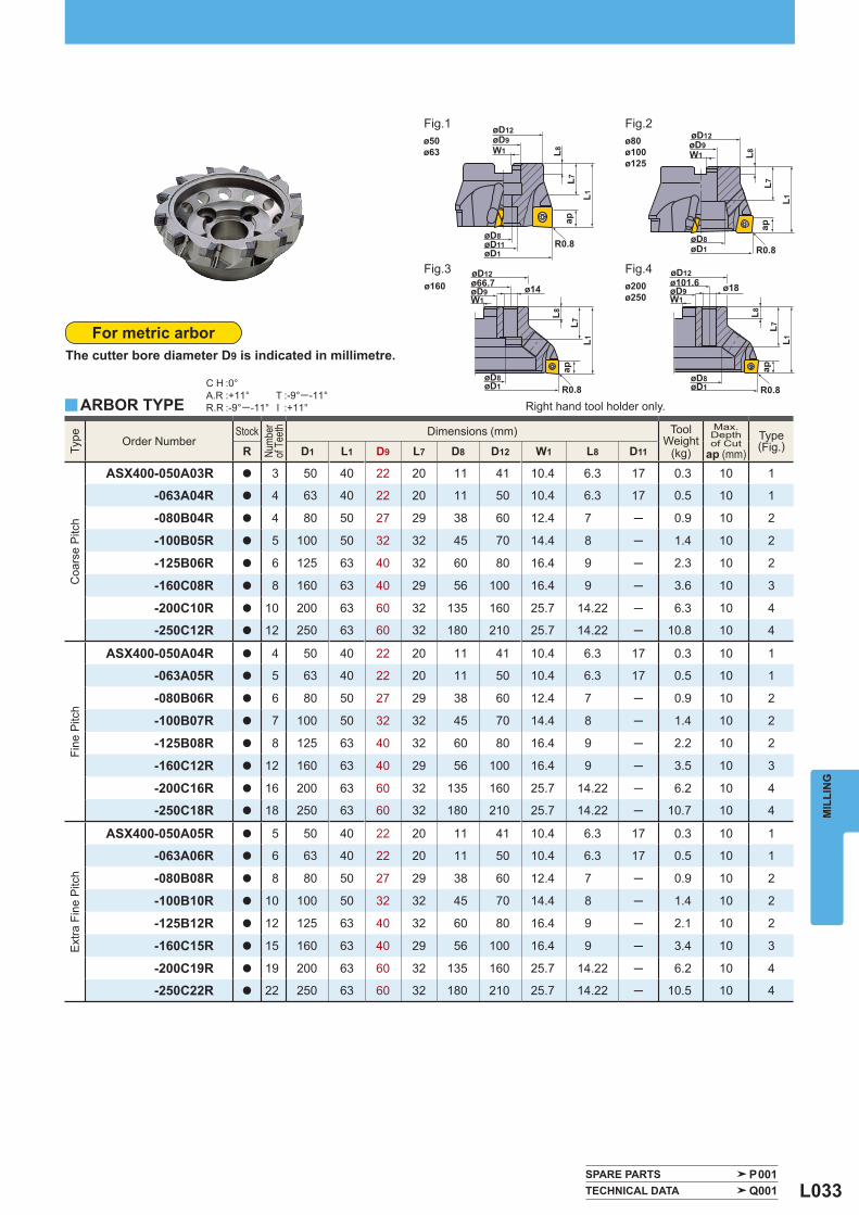
L033
Type
Order Number Stock
Num
ber
of T
eeth
Dimensions (mm) ToolWeight
(kg)
Max. Depthof Cut
ap (mm) Type
(Fig.) R D1 L1 D9 L7 D8 D12 W1 L8 D11
Coa
rse
Pitc
h
ASX400-050A03R a 3 50 40 22 20 11 41 10.4 6.3 17 0.3 10 1
-063A04R a 4 63 40 22 20 11 50 10.4 6.3 17 0.5 10 1
-080B04R a 4 80 50 27 29 38 60 12.4 7 ─ 0.9 10 2
-100B05R a 5 100 50 32 32 45 70 14.4 8 ─ 1.4 10 2
-125B06R a 6 125 63 40 32 60 80 16.4 9 ─ 2.3 10 2
-160C08R a 8 160 63 40 29 56 100 16.4 9 ─ 3.6 10 3
-200C10R a 10 200 63 60 32 135 160 25.7 14.22 ─ 6.3 10 4
-250C12R a 12 250 63 60 32 180 210 25.7 14.22 ─ 10.8 10 4
Fine
Pitc
h
ASX400-050A04R a 4 50 40 22 20 11 41 10.4 6.3 17 0.3 10 1
-063A05R a 5 63 40 22 20 11 50 10.4 6.3 17 0.5 10 1
-080B06R a 6 80 50 27 29 38 60 12.4 7 ─ 0.9 10 2
-100B07R a 7 100 50 32 32 45 70 14.4 8 ─ 1.4 10 2
-125B08R a 8 125 63 40 32 60 80 16.4 9 ─ 2.2 10 2
-160C12R a 12 160 63 40 29 56 100 16.4 9 ─ 3.5 10 3
-200C16R a 16 200 63 60 32 135 160 25.7 14.22 ─ 6.2 10 4
-250C18R a 18 250 63 60 32 180 210 25.7 14.22 ─ 10.7 10 4
Ext
ra F
ine
Pitc
h
ASX400-050A05R a 5 50 40 22 20 11 41 10.4 6.3 17 0.3 10 1
-063A06R a 6 63 40 22 20 11 50 10.4 6.3 17 0.5 10 1
-080B08R a 8 80 50 27 29 38 60 12.4 7 ─ 0.9 10 2
-100B10R a 10 100 50 32 32 45 70 14.4 8 ─ 1.4 10 2
-125B12R a 12 125 63 40 32 60 80 16.4 9 ─ 2.1 10 2
-160C15R a 15 160 63 40 29 56 100 16.4 9 ─ 3.4 10 3
-200C19R a 19 200 63 60 32 135 160 25.7 14.22 ─ 6.2 10 4
-250C22R a 22 250 63 60 32 180 210 25.7 14.22 ─ 10.5 10 4
y
C H :0°A.R :+11°R.R :-9°─ -11°
T :-9°─ -11°I :+11°
SPARE PARTS P001 TECHNICAL DATA Q001
ø50ø63
ø200ø250
ø160
ø80ø100ø125
MIL
LIN
G
For metric arborThe cutter bore diameter D9 is indicated in millimetre.
ARBOR TYPE Right hand tool holder only.
Fig.1 Fig.2
Fig.3 Fig.4
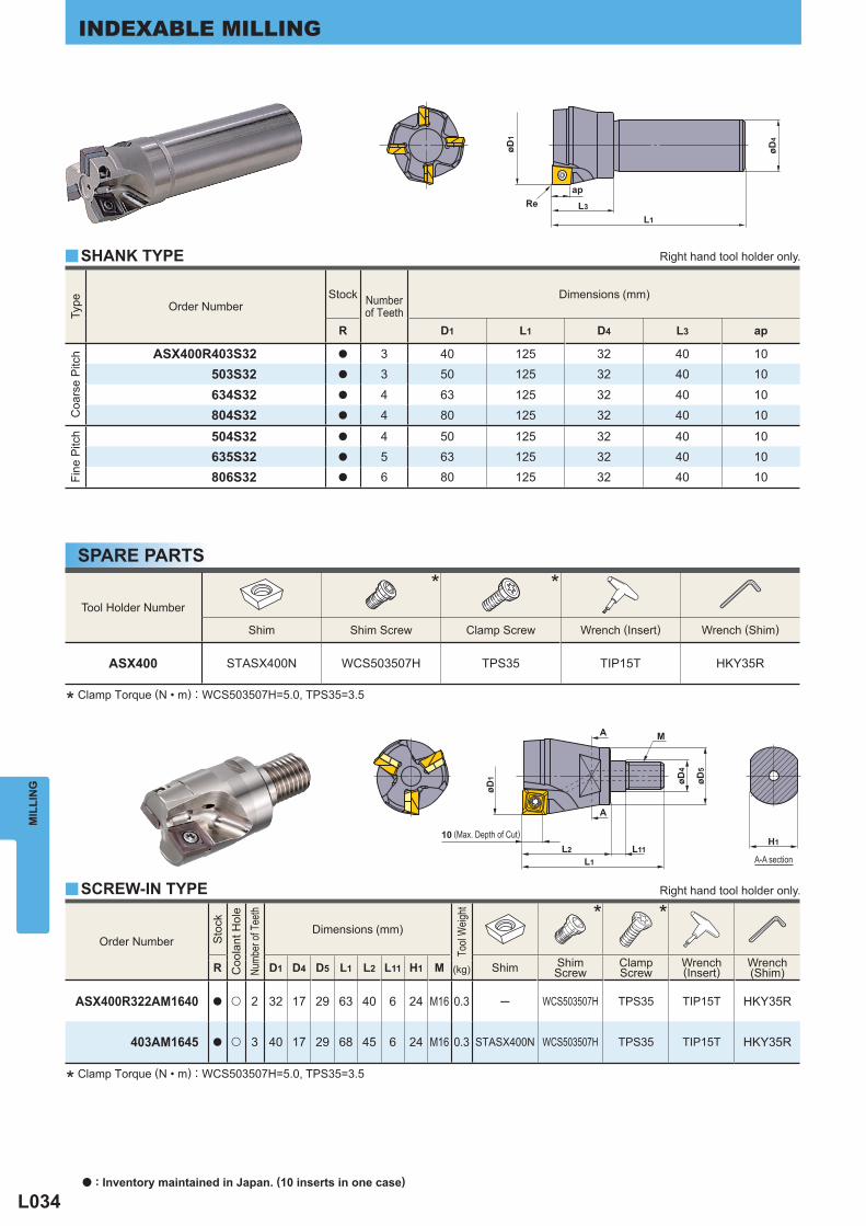
L034
Type
Order Number Stock Number
of Teeth Dimensions (mm)
R D1 L1 D4 L3 ap
Coa
rse
Pitc
h
ASX400R403S32 a 3 40 125 32 40 10503S32 a 3 50 125 32 40 10
634S32 a 4 63 125 32 40 10804S32 a 4 80 125 32 40 10
Fine
Pitc
h
504S32 a 4 50 125 32 40 10635S32 a 5 63 125 32 40 10806S32 a 6 80 125 32 40 10
Tool Holder Number
* *
Shim Shim Screw Clamp Screw Wrench (Insert) Wrench (Shim)
ASX400 STASX400N WCS503507H TPS35 TIP15T HKY35R
Order Number
Sto
ck
Coo
lant
Hol
e
Numb
er of
Tee
th
Dimensions (mm)
Tool
Weig
ht
* *
R D1 D4 D5 L1 L2 L11 H1 M Shim ShimScrew
ClampScrew
Wrench(Insert)
Wrench(Shim) (kg)
ASX400R322AM1640 a u 2 32 17 29 63 40 6 24 M16 0.3 ─ WCS503507H TPS35 TIP15T HKY35R
403AM1645 a u 3 40 17 29 68 45 6 24 M16 0.3 STASX400N WCS503507H TPS35 TIP15T HKY35R
y
y
MIL
LIN
GINDEXABLE MILLING
* Clamp Torque (N • m) : WCS503507H=5.0, TPS35=3.5
* Clamp Torque (N • m) : WCS503507H=5.0, TPS35=3.5
A-A section
SPARE PARTS
SHANK TYPE Right hand tool holder only.
Right hand tool holder only.
(Max. Depth of Cut)
SCREW-IN TYPE
a : Inventory maintained in Japan. (10 inserts in one case)
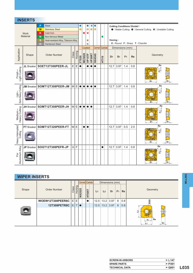
L035
WorkMaterial
P Steel
M Stainless Steel
K Cast Iron
N Non-ferrous Metal
S Heat-resistant Alloy, Titanium Alloy H Hardened Steel
App
licat
ion
Shape Order Number
Cla
ss
Hon
ing
Coated Cermet Carbide Dimensions (mm)
Geometry
F703
0M
C50
20VP
15TF
VP30
RT
NX4
545
HTi
10 D1 S1 F1 Re
Fini
sh─
Ligh
t Cut
ting
JL Breaker SOET12T308PEER-JL E E a a a a 12.7 3.97 1.4 0.8
Light─
Semi
-Hea
vy C
utting
JM Breaker SOMT12T308PEER-JM M E a a a a a 12.7 3.97 1.4 0.8
Med
ium─
Hea
vy C
uttin
g
JH Breaker SOMT12T308PEER-JH M E a a a a 12.7 3.97 1.4 0.8
Heav
y In
terru
pted
Cutti
ng
FT Breaker SOMT12T320PEER-FT M E a a 12.7 3.97 0.5 2.0
For
Alu
min
ium
Allo
y
JP Breaker SOGT12T308PEFR-JP G F a 12.7 3.97 1.4 0.8
Shape Order Number
Cla
ss
Hon
ing
Cermet Carbide Dimensions (mm)
Geometry
NX2
525
HTi
05T L1 L2 S1 F1 Re
WOEW12T308PEER8C E E a 12.5 13.2 3.97 8 0.812T308PETR8C E T a 12.5 13.2 3.97 8 0.8
SCREW-IN ARBORS L147 SPARE PARTS P001 TECHNICAL DATA Q001
MIL
LIN
G
INSERTS
WIPER INSERTS
Cutting Conditions (Guide) : : Stable Cutting : General Cutting : Unstable Cutting
Honing : E : Round F : Sharp T : Chamfer
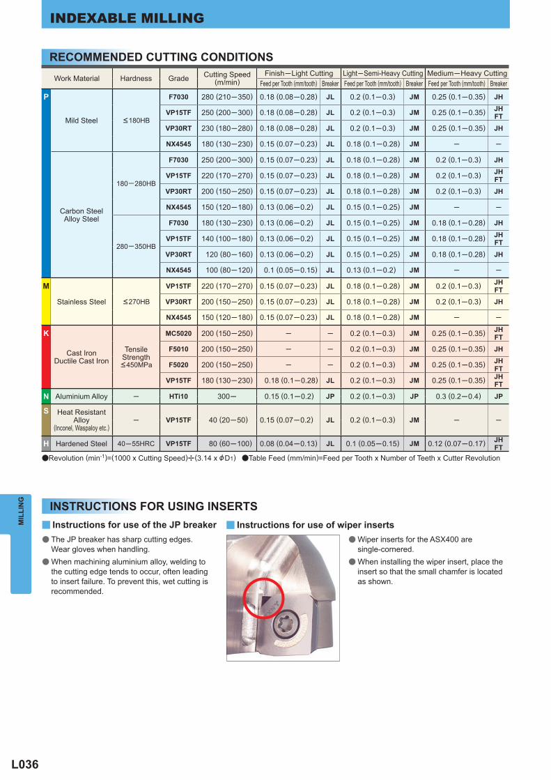
L036
Work Material Hardness Grade Cutting Speed(m/min)
Finish─Light Cutting Light─Semi-Heavy Cutting Medium─Heavy Cutting Feed per Tooth (mm/tooth) Breaker Feed per Tooth (mm/tooth) Breaker Feed per Tooth (mm/tooth) Breaker
P
Mild Steel <180HB
F7030 280 (210─350) 0.18 (0.08─0.28) JL 0.2 (0.1─0.3) JM 0.25 (0.1─0.35) JH
VP15TF 250 (200─300) 0.18 (0.08─0.28) JL 0.2 (0.1─0.3) JM 0.25 (0.1─0.35) JHFT
VP30RT 230 (180─280) 0.18 (0.08─0.28) JL 0.2 (0.1─0.3) JM 0.25 (0.1─0.35) JH
NX4545 180 (130─230) 0.15 (0.07─0.23) JL 0.18 (0.1─0.28) JM ─ ─
Carbon SteelAlloy Steel
180─280HB
F7030 250 (200─300) 0.15 (0.07─0.23) JL 0.18 (0.1─0.28) JM 0.2 (0.1─0.3) JH
VP15TF 220 (170─270) 0.15 (0.07─0.23) JL 0.18 (0.1─0.28) JM 0.2 (0.1─0.3) JHFT
VP30RT 200 (150─250) 0.15 (0.07─0.23) JL 0.18 (0.1─0.28) JM 0.2 (0.1─0.3) JH
NX4545 150 (120─180) 0.13 (0.06─0.2) JL 0.15 (0.1─0.25) JM ─ ─
280─350HB
F7030 180 (130─230) 0.13 (0.06─0.2) JL 0.15 (0.1─0.25) JM 0.18 (0.1─0.28) JH
VP15TF 140 (100─180) 0.13 (0.06─0.2) JL 0.15 (0.1─0.25) JM 0.18 (0.1─0.28) JHFT
VP30RT 120 (80─160) 0.13 (0.06─0.2) JL 0.15 (0.1─0.25) JM 0.18 (0.1─0.28) JH
NX4545 100 (80─120) 0.1 (0.05─0.15) JL 0.13 (0.1─0.2) JM ─ ─
M
Stainless Steel <270HB
VP15TF 220 (170─270) 0.15 (0.07─0.23) JL 0.18 (0.1─0.28) JM 0.2 (0.1─0.3) JHFT
VP30RT 200 (150─250) 0.15 (0.07─0.23) JL 0.18 (0.1─0.28) JM 0.2 (0.1─0.3) JH
NX4545 150 (120─180) 0.15 (0.07─0.23) JL 0.18 (0.1─0.28) JM ─ ─
K
Cast IronDuctile Cast Iron
TensileStrength <450MPa
MC5020 200 (150─250) ─ ─ 0.2 (0.1─0.3) JM 0.25 (0.1─0.35) JHFT
F5010 200 (150─250) ─ ─ 0.2 (0.1─0.3) JM 0.25 (0.1─0.35) JH
F5020 200 (150─250) ─ ─ 0.2 (0.1─0.3) JM 0.25 (0.1─0.35) JHFT
VP15TF 180 (130─230) 0.18 (0.1─0.28) JL 0.2 (0.1─0.3) JM 0.25 (0.1─0.35) JHFT
N Aluminium Alloy ─ HTi10 300─ 0.15 (0.1─0.2) JP 0.2 (0.1─0.3) JP 0.3 (0.2─0.4) JP
S Heat ResistantAlloy
(Inconel, Waspaloy etc.) ─ VP15TF 40 (20─50) 0.15 (0.07─0.2) JL 0.2 (0.1─0.3) JM ─ ─
H Hardened Steel 40─55HRC VP15TF 80 (60─100) 0.08 (0.04─0.13) JL 0.1 (0.05─0.15) JM 0.12 (0.07─0.17) JHFT
y yMIL
LIN
GINDEXABLE MILLING
The JP breaker has sharp cutting edges. Wear gloves when handling.When machining aluminium alloy, welding to the cutting edge tends to occur, often leading to insert failure. To prevent this, wet cutting is recommended.
Wiper inserts for the ASX400 are single-cornered.When installing the wiper insert, place the insert so that the small chamfer is located as shown.
Instructions for use of the JP breaker Instructions for use of wiper inserts●
●
●
●
RECOMMENDED CUTTING CONDITIONS
INSTRUCTIONS FOR USING INSERTS
aRevolution (min-1)=(1000 x Cutting Speed)u(3.14 x &D1) aTable Feed (mm/min)=Feed per Tooth x Number of Teeth x Cutter Revolution
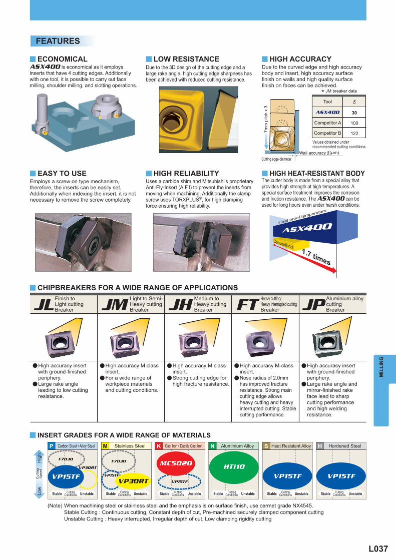
L037
MIL
LIN
G
P M HS N
ASX400 30
100
122
ASX400
y
y
y
y
y
y
y y
K
HTi10
VP15TF VP15TFVP30RT
VP15TF VP15TF
F7030 F7030
VP30RT
VP15TF
MC5020
(Note) When machining steel or stainless steel and the emphasis is on surface finish, use cermet grade NX4545. Stable Cutting : Continuous cutting, Constant depth of cut, Pre-machined securely clamped component cutting Unstable Cutting : Heavy interrupted, Irregular depth of cut, Low clamping rigidity cutting
FEATURES
ECONOMICAL
CHIPBREAKERS FOR A WIDE RANGE OF APPLICATIONS
LOW RESISTANCE
JL JM JPFTJH
ASX400 is economical as it employs inserts that have 4 cutting edges. Additionally with one tool, it is possible to carry out face milling, shoulder milling, and slotting operations.
EASY TO USEEmploys a screw on type mechanism, therefore, the inserts can be easily set. Additionally when indexing the insert, it is not necessary to remove the screw completely.
Due to the 3D design of the cutting edge and a large rake angle, high cutting edge sharpness has been achieved with reduced cutting resistance.
HIGH ACCURACYDue to the curved edge and high accuracy body and insert, high accuracy surface finish on walls and high quality surface finish on faces can be achieved.
Tool
Competitor A
Competitor B
a
a
High accuracy insert with ground-finished periphery.Large rake angle leading to low cutting resistance.
a
a
High accuracy M class insert.For a wide range of workpiece materials and cutting conditions.
a
a
High accuracy M class insert.Strong cutting edge for high fracture resistance.
a
a
High accuracy M-class insert.Nose radius of 2.0mm has improved fracture resistance. Strong main cutting edge allows heavy cutting and heavy interrupted cutting. Stable cutting performance.
a
a
High accuracy insert with ground-finished periphery.Large rake angle and mirror-finished rake face lead to sharp cutting performance and high welding resistance.
Uses a carbide shim and Mitsubishi's proprietary Anti-Fly-Insert (A.F.I) to prevent the inserts from moving when machining. Additionally the clamp screw uses TORXPLUS®, for high clamping force ensuring high reliability.
HIGH RELIABILITYThe cutter body is made from a special alloy that provides high strength at high temperatures. A special surface treatment improves the corrosion and friction resistance. The ASX400 can be used for long hours even under harsh conditions.
HIGH HEAT-RESISTANT BODY
Conventional
Heat proof temperature
1.7 times
(!m)
7mm
pitc
h x
3
Wall accuracyCutting edge diameter
Aluminium alloy cuttingBreaker
Finish to Light cuttingBreaker
Light to Semi-Heavy cuttingBreaker
Medium to Heavy cuttingBreaker
Heavy cutting/Heavy interrupted cuttingBreaker
* JM breaker data
Values obtained under recommended cutting conditions.
Stainless Steel Aluminium Alloy Heat Resistant Alloy Hardened SteelCarbon Steel • Alloy Steel
Low
Hig
hC
uttin
gS
peed
INSERT GRADES FOR A WIDE RANGE OF MATERIALS
UnstableStable CuttingConditionsUnstableStable Cutting
ConditionsUnstableStable CuttingConditions UnstableStable Cutting
ConditionsUnstableStable CuttingConditions
Cast Iron • Ductile Cast Iron
UnstableStable CuttingConditions
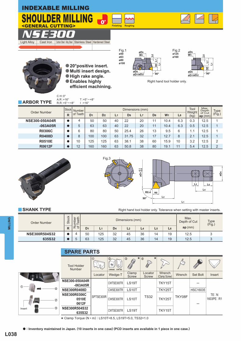
L038
Light Alloy Cast Iron Carbon Steel · Alloy Steel Stainless Steel Hardened Steel NSE300
Order Number Stock Number
of Teeth Dimensions (mm) Tool
Weight (kg)
Max. Depthof Cut
ap (mm) Type
(Fig.) R D1 D2 L1 D9 L7 D8 W1 L8
NSE300-050A04R a 4 50 50 40 22 20 11 10.4 6.3 0.3 12.5 1-063A05R a 5 63 63 40 22 20 11 10.4 6.3 0.5 12.5 1R0306C a 6 80 80 50 25.4 26 13 9.5 6 1.1 12.5 1R0408D a 8 100 100 63 31.75 32 17 12.7 8 2.1 12.5 1R0510E a 10 125 125 63 38.1 38 60 15.9 10 3.2 12.5 2R0612F a 12 160 160 63 50.8 38 80 19.1 11 5.4 12.5 2
Tool HolderNumber
* *
Locator Wedge-T ClampScrew
LocatorScrew
Wrench(Clamp Screw) Wrench Set Bolt Insert
NSE300-050A04R-063A05R
SPTSE300R
CWTSE300TR LS19T
TS32
TKY15T
TKY08F
─
TEpN1603PEpR1
NSE300R0408D CWSE300TR LS10T TKY25T HSC16035NSE300R0306C
0510E0612F
CWSE300TR LS10T TKY25T─
NSE300R504S32635S32 CWTSE300TR LS19T TKY15T
Order Number
Sto
ck
Num
ber
of T
eeth
Dimensions (mm) Max. Depth of Cut
ap (mm) Type
(Fig.) R D1 L1 D4 L2 L4 L5 L6
NSE300R504S32 a 4 50 125 32 45 36 14 19 12.5 3635S32 a 5 63 125 32 45 36 14 19 12.5 3
y
y
C H :0°A.R :+16°R.R :+5°─+8°
T :+5°─+8°I :+16°
z x c v
ø50ø63ø80ø100
ø125ø160
MIL
LIN
GINDEXABLE MILLING
* Clamp Torque (N • m) : LS10T=8.5, LS19T=5.0, TS32=1.0
SPARE PARTS
ARBOR TYPE
SHANK TYPE
Right hand tool holder only.
SHOULDER MILLING<GENERAL CUTTING>
Fig.1 Fig.2
Fig.3
Finishing Roughing
Insert
20°positive insert.Multi insert design.High rake angle.Enables highly effi cient machining.
a
a
a
a
Right hand tool holder only. Tolerance when setting with master inserts.
a : Inventory maintained in Japan. (10 inserts in one case) (PCD inserts are available in 1 piece in one case.)
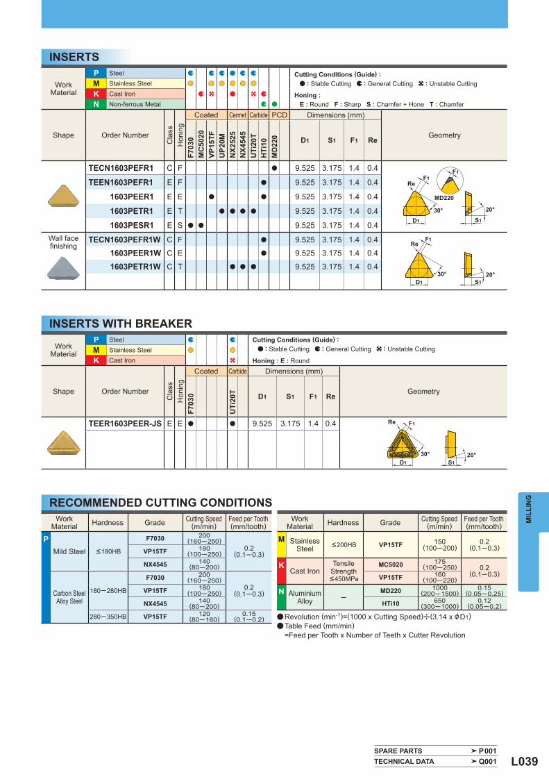
L039
WorkMaterial
P Steel M Stainless Steel K Cast Iron
Shape Order Number
Cla
ss
Hon
ing
Coated Carbide Dimensions (mm)
Geometry
F703
0
UTi
20T D1 S1 F1 Re
TEER1603PEER-JS E E a a 9.525 3.175 1.4 0.4
WorkMaterial
P Steel M Stainless Steel
K Cast Iron N Non-ferrous Metal
Shape Order Number
Cla
ss
Hon
ing
Coated Cermet Carbide PCD Dimensions (mm)
Geometry
F703
0M
C50
20VP
15TF
UP2
0MN
X252
5N
X454
5U
Ti20
TH
Ti10
MD
220 D1 S1 F1 Re
TECN1603PEFR1 C F a 9.525 3.175 1.4 0.4
TEEN1603PEFR1 E F a 9.525 3.175 1.4 0.4
1603PEER1 E E a a 9.525 3.175 1.4 0.4
1603PETR1 E T a a a a 9.525 3.175 1.4 0.4
1603PESR1 E S a a 9.525 3.175 1.4 0.4 Wall facefi nishing
TECN1603PEFR1W C F a 9.525 3.175 1.4 0.4
1603PEER1W C E a 9.525 3.175 1.4 0.4
1603PETR1W C T a a a 9.525 3.175 1.4 0.4
SPARE PARTS P001 TECHNICAL DATA Q001
WorkMaterial Hardness Grade Cutting Speed
(m/min) Feed per Tooth(mm/tooth)
P Mild Steel <180HB
F7030 200(160─250)
0.2(0.1─0.3)VP15TF 180
(100─250)
NX4545 140(80─200)
Carbon SteelAlloy Steel
180─280HB
F7030 200(160─250)
0.2(0.1─0.3)VP15TF 180
(100─250)
NX4545 140(80─200)
280─350HB VP15TF 120(80─160)
0.15(0.1─0.2)
WorkMaterial Hardness Grade Cutting Speed
(m/min) Feed per Tooth(mm/tooth)
M StainlessSteel <200HB VP15TF 150
(100─200)0.2
(0.1─0.3)
K Cast Iron
Tensile Strength <450MPa
MC5020 175(100─250) 0.2
(0.1─0.3)VP15TF 160(100─220)
N AluminiumAlloy ─
MD220 1000(200─1500)
0.15(0.05─0.25)
HTi10 650(300─1000)
0.12(0.05─0.2)
MIL
LIN
G
INSERTS
INSERTS WITH BREAKER
RECOMMENDED CUTTING CONDITIONS
a Revolution (min-1)=(1000 x Cutting Speed)u(3.14 x &D1)a Table Feed (mm/min) =Feed per Tooth x Number of Teeth x Cutter Revolution
Cutting Conditions (Guide) : : Stable Cutting : General Cutting : Unstable Cutting
Honing : E : Round
Cutting Conditions (Guide) : : Stable Cutting : General Cutting : Unstable Cutting
Honing : E : Round F : Sharp S : Chamfer + Hone T : Chamfer
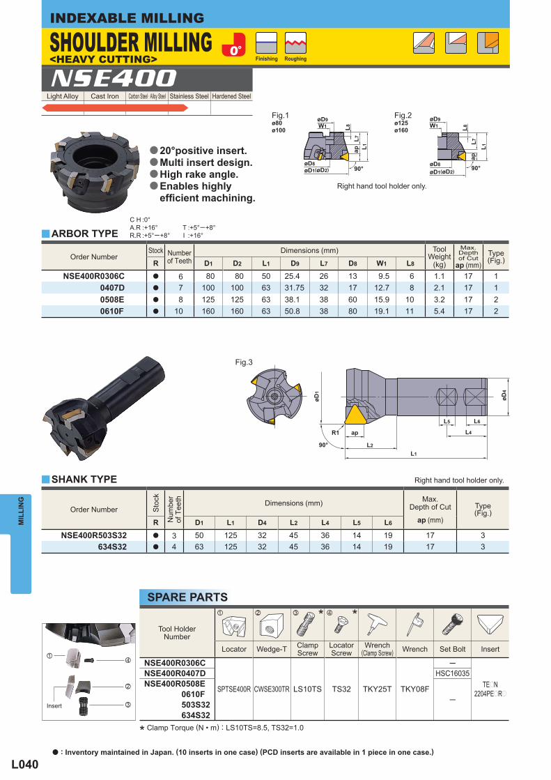
L040
Light Alloy Cast Iron Carbon Steel · Alloy Steel Stainless Steel Hardened Steel NSE400
Tool HolderNumber
* *
Locator Wedge-T ClampScrew
LocatorScrew
Wrench(Clamp Screw) Wrench Set Bolt Insert
NSE400R0306C
SPTSE400R CWSE300TR LS10TS TS32 TKY25T TKY08F
─
TEpN2204PEpRp
NSE400R0407D HSC16035NSE400R0508E
0610F503S32634S32
─
Order Number Stock Number
of Teeth Dimensions (mm) Tool
Weight (kg)
Max. Depthof Cut
ap (mm) Type
(Fig.) R D1 D2 L1 D9 L7 D8 W1 L8
NSE400R0306C a 6 80 80 50 25.4 26 13 9.5 6 1.1 17 10407D a 7 100 100 63 31.75 32 17 12.7 8 2.1 17 10508E a 8 125 125 63 38.1 38 60 15.9 10 3.2 17 20610F a 10 160 160 63 50.8 38 80 19.1 11 5.4 17 2
Order Number
Sto
ck
Num
ber
of T
eeth
Dimensions (mm) Max. Depth of Cut
ap (mm) Type
(Fig.) R D1 L1 D4 L2 L4 L5 L6
NSE400R503S32 a 3 50 125 32 45 36 14 19 17 3634S32 a 4 63 125 32 45 36 14 19 17 3
y
y
C H :0°A.R :+16°R.R :+5°─+8°
T :+5°─+8°I :+16°
z x c v
ø80ø100
ø125ø160
MIL
LIN
GINDEXABLE MILLING
* Clamp Torque (N • m) : LS10TS=8.5, TS32=1.0
SPARE PARTS
ARBOR TYPE
SHANK TYPE
Right hand tool holder only.
Right hand tool holder only.
SHOULDER MILLING<HEAVY CUTTING>
Fig.1 Fig.2
Fig.3
Finishing Roughing
Insert
20°positive insert.Multi insert design.High rake angle.Enables highly effi cient machining.
a
a
a
a
a : Inventory maintained in Japan. (10 inserts in one case) (PCD inserts are available in 1 piece in one case.)
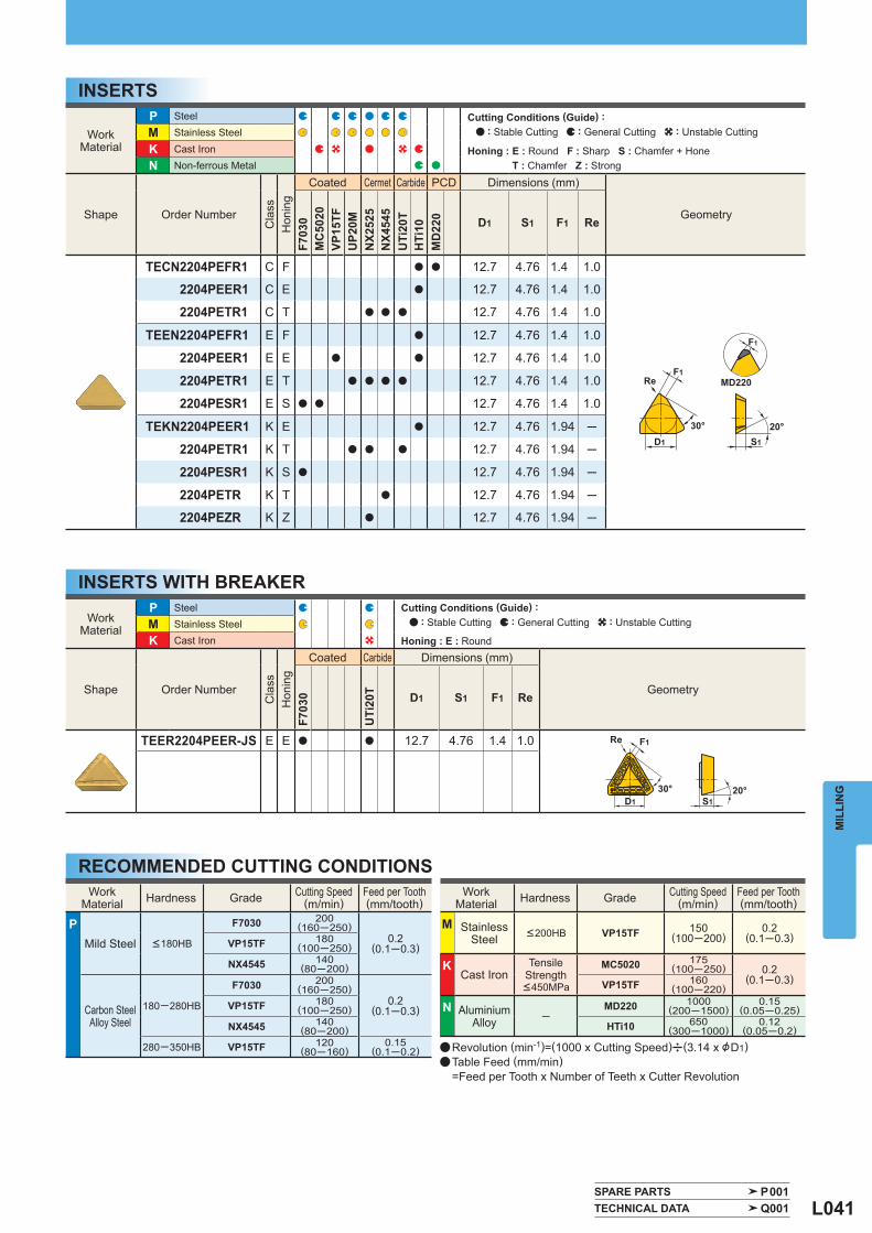
L041
WorkMaterial
P Steel
M Stainless Steel
K Cast Iron N Non-ferrous Metal
Shape Order Number
Cla
ss
Hon
ing
Coated Cermet Carbide PCD Dimensions (mm)
Geometry
F703
0M
C50
20VP
15TF
UP2
0MN
X252
5N
X454
5U
Ti20
TH
Ti10
MD
220 D1 S1 F1 Re
TECN2204PEFR1 C F a a 12.7 4.76 1.4 1.0
2204PEER1 C E a 12.7 4.76 1.4 1.0
2204PETR1 C T a a a 12.7 4.76 1.4 1.0
TEEN2204PEFR1 E F a 12.7 4.76 1.4 1.0
2204PEER1 E E a a 12.7 4.76 1.4 1.0
2204PETR1 E T a a a a 12.7 4.76 1.4 1.0
2204PESR1 E S a a 12.7 4.76 1.4 1.0
TEKN2204PEER1 K E a 12.7 4.76 1.94 ─
2204PETR1 K T a a a 12.7 4.76 1.94 ─
2204PESR1 K S a 12.7 4.76 1.94 ─
2204PETR K T a 12.7 4.76 1.94 ─
2204PEZR K Z a 12.7 4.76 1.94 ─
WorkMaterial
P Steel
M Stainless Steel K Cast Iron
Shape Order Number
Cla
ss
Hon
ing
Coated Carbide Dimensions (mm)
Geometry
F703
0
UTi
20T D1 S1 F1 Re
TEER2204PEER-JS E E a a 12.7 4.76 1.4 1.0
SPARE PARTS P001 TECHNICAL DATA Q001
WorkMaterial Hardness Grade Cutting Speed
(m/min) Feed per Tooth(mm/tooth)
P Mild Steel <180HB
F7030 200(160─250)
0.2(0.1─0.3)VP15TF 180
(100─250)
NX4545 140(80─200)
Carbon SteelAlloy Steel
180─280HB
F7030 200(160─250)
0.2(0.1─0.3)VP15TF 180
(100─250)
NX4545 140(80─200)
280─350HB VP15TF 120(80─160)
0.15(0.1─0.2)
WorkMaterial Hardness Grade Cutting Speed
(m/min) Feed per Tooth(mm/tooth)
M StainlessSteel <200HB VP15TF 150
(100─200)0.2
(0.1─0.3)
K Cast Iron
Tensile Strength <450MPa
MC5020 175(100─250) 0.2
(0.1─0.3)VP15TF 160(100─220)
N AluminiumAlloy ─
MD220 1000(200─1500)
0.15(0.05─0.25)
HTi10 650(300─1000)
0.12(0.05─0.2)
MIL
LIN
G
INSERTS
INSERTS WITH BREAKER
RECOMMENDED CUTTING CONDITIONS
a Revolution (min-1)=(1000 x Cutting Speed)u(3.14 x &D1)a Table Feed (mm/min) =Feed per Tooth x Number of Teeth x Cutter Revolution
Cutting Conditions (Guide) : : Stable Cutting : General Cutting : Unstable Cutting
Honing : E : Round
Cutting Conditions (Guide) : : Stable Cutting : General Cutting : Unstable Cutting
Honing : E : Round F : Sharp S : Chamfer + Hone T : Chamfer Z : Strong
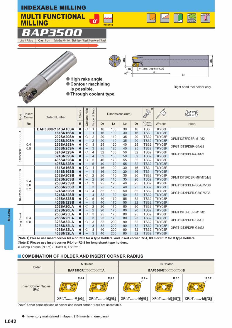
L042
Light Alloy Cast Iron Carbon Steel · Alloy Steel Stainless Steel Hardened Steel BAP3500
Holder A Holder B Holder
BAP3500RooooooooA BAP3500RooooooooB
Insert Corner Radius (Re)
XPoT........-M1/G1 XPoT........-M2/G2 XPoT........-M6/G6 XPoT........-M75/G75 XPoT........-M8/G8
Type
InsertCorner Order Number
Sto
ck
Coo
lant
Hol
e
Numb
er of
Tee
th
Dimensions (mm)*
Re R D1 L1 L2 D4 Clamp Screw Wrench Insert
BA
P35
00Rpppppppp
A
0.40.8
BAP3500R161SA16SA a u 1 16 100 30 16 TS3 TKY08F
XPMT13T3PDER-M1/M2
XPGT13T3PDER-G1/G2
XPGT13T3PDFR-G1/G2
161SN16SA a ─ 1 16 100 30 16 TS3 TKY08F202SA20SA a u 2 20 110 35 20 TS32 TKY08F202SN20SA a ─ 2 20 110 35 20 TS32 TKY08F253SA25SA a u 3 25 120 40 25 TS32 TKY08F253SN25SA a ─ 3 25 120 40 25 TS32 TKY08F324SA32SA a u 4 32 130 50 32 TS32 TKY08F324SN32SA a ─ 4 32 130 50 32 TS32 TKY08F405SA32SA a u 5 40 170 55 32 TS32 TKY08F405SN32SA a ─ 5 40 170 55 32 TS32 TKY08F
BA
P35
00Rpppppppp
B
2.43.03.2
161SA16SB a u 1 16 100 30 16 TS3 TKY08F
XPMT13T3PDER-M6/M75/M8
XPGT13T3PDER-G6/G75/G8
XPGT13T3PDFR-G6/G75/G8
161SN16SB a ─ 1 16 100 30 16 TS3 TKY08F202SA20SB a u 2 20 110 35 20 TS32 TKY08F202SN20SB a ─ 2 20 110 35 20 TS32 TKY08F253SA25SB a u 3 25 120 40 25 TS32 TKY08F253SN25SB a ─ 3 25 120 40 25 TS32 TKY08F324SA32SB a u 4 32 130 50 32 TS32 TKY08F324SN32SB a ─ 4 32 130 50 32 TS32 TKY08F405SA32SB a u 5 40 170 55 32 TS32 TKY08F405SN32SB a ─ 5 40 170 55 32 TS32 TKY08F
Long
Sha
nk
0.40.8
202SA20LA a u 2 20 170 80 20 TS32 TKY08F
XPMT13T3PDER-M1/M2
XPGT13T3PDER-G1/G2
XPGT13T3PDFR-G1/G2
202SN20LA a ─ 2 20 170 80 20 TS32 TKY08F253SA25LA a u 3 25 170 80 25 TS32 TKY08F253SN25LA a ─ 3 25 170 80 25 TS32 TKY08F323SA32LA a u 3 32 200 90 32 TS32 TKY08F323SN32LA a ─ 3 32 200 90 32 TS32 TKY08F403SA32LA a u 3 40 200 90 32 TS32 TKY08F403SN32LA a ─ 3 40 200 90 32 TS32 TKY08F
y
MIL
LIN
GINDEXABLE MILLINGMULTI FUNCTIONAL MILLING
(Note 1) Please use insert corner R0.4 or R0.8 for A type holders, and insert corner R2.4, R3.0 or R3.2 for B type holders.(Note 2) Please use insert corner R0.4 or R0.8 for long shank type holders.
(Note) Other combinations of holder and insert corner R are not acceptable.
COMBINATION OF HOLDER AND INSERT CORNER RADIUS* Clamp Torque (N • m) : TS3=1.0, TS32=1.0
Including Flat faces
Right hand tool holder only.
Roughing
(Max. Depth of Cut)
High rake angle.Contour machining is possible. Through coolant type.
a
a
a
a : Inventory maintained in Japan. (10 inserts in one case)
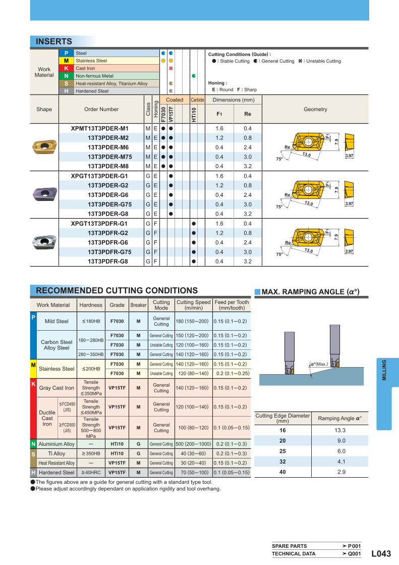
L043
WorkMaterial
P Steel
M Stainless Steel
K Cast Iron
N Non-ferrous Metal
S Heat-resistant Alloy, Titanium Alloy H Hardened Steel
Shape Order Number
Cla
ss
Hon
ing
Coated Carbide Dimensions (mm)
Geometry
F703
0VP
15TF
HTi
10 F1 Re
XPMT13T3PDER-M1 M E a a 1.6 0.413T3PDER-M2 M E a a 1.2 0.8
13T3PDER-M6 M E a a 0.4 2.4
13T3PDER-M75 M E a a 0.4 3.013T3PDER-M8 M E a a 0.4 3.2
XPGT13T3PDER-G1 G E a 1.6 0.413T3PDER-G2 G E a 1.2 0.8
13T3PDER-G6 G E a 0.4 2.4
13T3PDER-G75 G E a 0.4 3.013T3PDER-G8 G E a 0.4 3.2
XPGT13T3PDFR-G1 G F a 1.6 0.413T3PDFR-G2 G F a 1.2 0.8
13T3PDFR-G6 G F a 0.4 2.4
13T3PDFR-G75 G F a 0.4 3.013T3PDFR-G8 G F a 0.4 3.2
Cutting Edge Diameter(mm) Ramping Angle %°
16 13.3
20 9.0
25 6.0
32 4.1
40 2.9
Work Material Hardness Grade Breaker CuttingMode
Cutting Speed(m/min)
Feed per Tooth(mm/tooth)
P Mild Steel <180HB F7030 M General
Cutting 180 (150─200) 0.15 (0.1─0.2)
Carbon SteelAlloy Steel
180─280HB F7030 M General Cutting 150 (120─200) 0.15 (0.1─0.2)
F7030 M Unstable Cutting 120 (100─160) 0.15 (0.1─0.2)
280─350HB F7030 M General Cutting 140 (120─160) 0.15 (0.1─0.2)
M Stainless Steel <200HB
F7030 M General Cutting 140 (120─160) 0.15 (0.1─0.2)
F7030 M Unstable Cutting 120 (80─140) 0.2 (0.1─0.25)
K Gray Cast Iron
TensileStrength<350MPa
VP15TF M GeneralCutting 140 (120─160) 0.15 (0.1─0.2)
DuctileCastIron
<FCD450(JIS)
TensileStrength<450MPa
VP15TF M GeneralCutting 120 (100─140) 0.15 (0.1─0.2)
>FCD500(JIS)
TensileStrength500─800
MPa
VP15TF M GeneralCutting 100 (80─120) 0.1 (0.05─0.15)
N Aluminium Alloy ─ HTi10 G General Cutting 500 (200─1000) 0.2 (0.1─0.3)
S Ti Alloy >350HB HTi10 G General Cutting 40 (30─60) 0.2 (0.1─0.3)
Heat Resistant Alloy ─ VP15TF M General Cutting 30 (20─40) 0.15 (0.1─0.2)
H Hardened Steel >40HRC VP15TF M General Cutting 70 (50─100) 0.1 (0.05─0.15)
y
SPARE PARTS P001 TECHNICAL DATA Q001
MIL
LIN
G
INSERTS
MAX. RAMPING ANGLE (%°)
(Max.)
RECOMMENDED CUTTING CONDITIONS
a The fi gures above are a guide for general cutting with a standard type tool.a Please adjust accordingly dependant on application rigidity and tool overhang.
Cutting Conditions (Guide) : : Stable Cutting : General Cutting : Unstable Cutting
Honing : E : Round F : Sharp
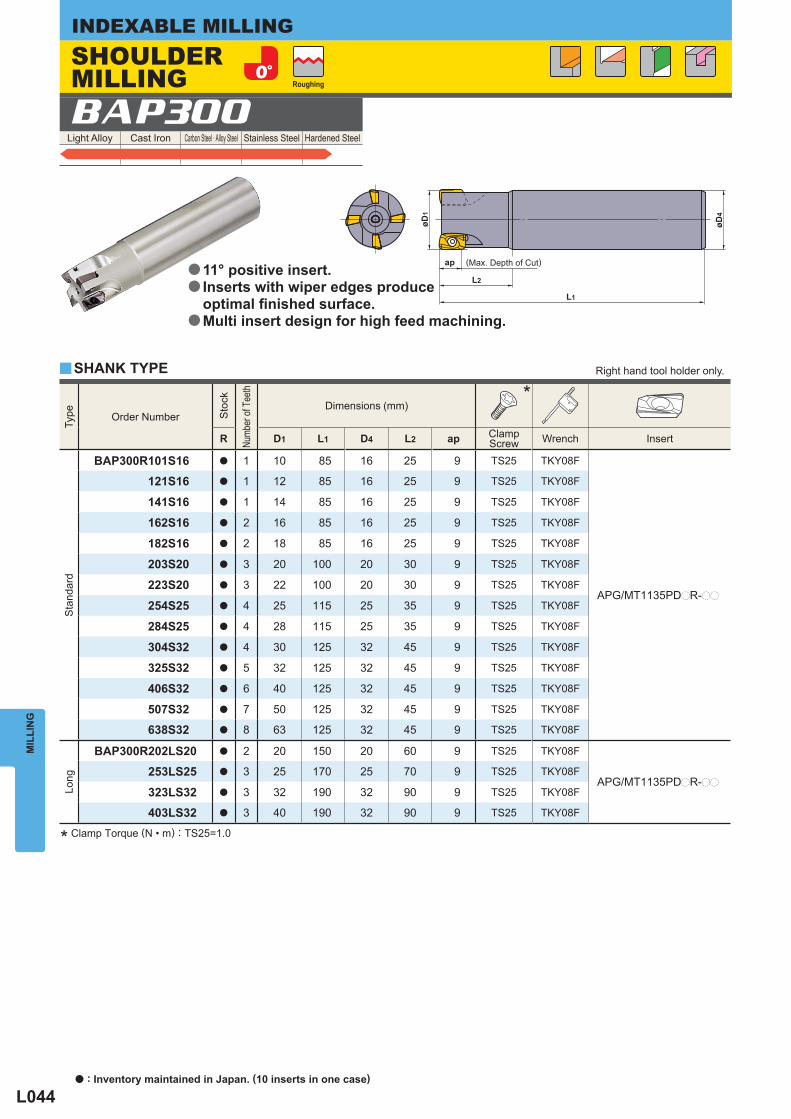
L044
Light Alloy Cast Iron Carbon Steel · Alloy Steel Stainless Steel Hardened Steel
Type
Order Number
Sto
ck
Numb
er of
Tee
th
Dimensions (mm)*
R D1 L1 D4 L2 ap Clamp Screw Wrench Insert
Sta
ndar
d
BAP300R101S16 a 1 10 85 16 25 9 TS25 TKY08F
APG/MT1135PDpR-pp
121S16 a 1 12 85 16 25 9 TS25 TKY08F
141S16 a 1 14 85 16 25 9 TS25 TKY08F
162S16 a 2 16 85 16 25 9 TS25 TKY08F
182S16 a 2 18 85 16 25 9 TS25 TKY08F
203S20 a 3 20 100 20 30 9 TS25 TKY08F
223S20 a 3 22 100 20 30 9 TS25 TKY08F
254S25 a 4 25 115 25 35 9 TS25 TKY08F
284S25 a 4 28 115 25 35 9 TS25 TKY08F
304S32 a 4 30 125 32 45 9 TS25 TKY08F
325S32 a 5 32 125 32 45 9 TS25 TKY08F
406S32 a 6 40 125 32 45 9 TS25 TKY08F
507S32 a 7 50 125 32 45 9 TS25 TKY08F
638S32 a 8 63 125 32 45 9 TS25 TKY08F
Long
BAP300R202LS20 a 2 20 150 20 60 9 TS25 TKY08F
APG/MT1135PDpR-pp253LS25 a 3 25 170 25 70 9 TS25 TKY08F
323LS32 a 3 32 190 32 90 9 TS25 TKY08F
403LS32 a 3 40 190 32 90 9 TS25 TKY08F
BAP300
y
L2
øD4
L1
ap
øD1
MIL
LIN
GINDEXABLE MILLING
* Clamp Torque (N • m) : TS25=1.0
SHANK TYPE Right hand tool holder only.
SHOULDER MILLING Roughing
(Max. Depth of Cut)11° positive insert.Inserts with wiper edges produce optimal fi nished surface. Multi insert design for high feed machining.
a
a
a
a : Inventory maintained in Japan. (10 inserts in one case)
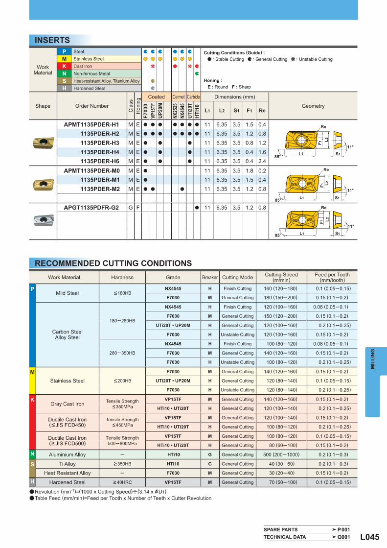
L045
WorkMaterial
P Steel M Stainless Steel
K Cast Iron
N Non-ferrous Metal
S Heat-resistant Alloy, Titanium Alloy H Hardened Steel
Shape Order Number
Cla
ss
Hon
ing
Coated Cermet Carbide Dimensions (mm)
Geometry
F703
0VP
15TF
UP20
M
NX25
25NX
4545
UTi2
0TH
Ti10 L1 L2 S1 F1 Re
APMT1135PDER-H1 M E a a a a a a a 11 6.35 3.5 1.5 0.41135PDER-H2 M E a a a a a a a 11 6.35 3.5 1.2 0.8
1135PDER-H3 M E a a a 11 6.35 3.5 0.8 1.2
1135PDER-H4 M E a a a 11 6.35 3.5 0.4 1.61135PDER-H6 M E a a a 11 6.35 3.5 0.4 2.4
APMT1135PDER-M0 M E a 11 6.35 3.5 1.8 0.21135PDER-M1 M E a 11 6.35 3.5 1.5 0.4
1135PDER-M2 M E a a a 11 6.35 3.5 1.2 0.8
APGT1135PDFR-G2 G F a 11 6.35 3.5 1.2 0.8
Work Material Hardness Grade Breaker Cutting Mode Cutting Speed(m/min)
Feed per Tooth(mm/tooth)
P Mild Steel <180HB
NX4545 H Finish Cutting 160 (120─180) 0.1 (0.05─0.15)
F7030 M General Cutting 180 (150─200) 0.15 (0.1─0.2)
Carbon SteelAlloy Steel
180─280HB
NX4545 H Finish Cutting 120 (100─160) 0.08 (0.05─0.1)
F7030 M General Cutting 150 (120─200) 0.15 (0.1─0.2)
UTi20T • UP20M H General Cutting 120 (100─160) 0.2 (0.1─0.25)
F7030 H Unstable Cutting 120 (100─160) 0.15 (0.1─0.2)
280─350HB
NX4545 H Finish Cutting 100 (80─120) 0.08 (0.05─0.1)
F7030 M General Cutting 140 (120─160) 0.15 (0.1─0.2)
F7030 H Unstable Cutting 100 (80─120) 0.2 (0.1─0.25)
M Stainless Steel <200HB
F7030 M General Cutting 140 (120─160) 0.15 (0.1─0.2)
UTi20T • UP20M H General Cutting 120 (80─140) 0.1 (0.05─0.15)
F7030 H Unstable Cutting 120 (80─140) 0.2 (0.1─0.25)
K Gray Cast Iron Tensile Strength
<350MPa VP15TF M General Cutting 140 (120─160) 0.15 (0.1─0.2)
HTi10 • UTi20T H General Cutting 120 (100─140) 0.2 (0.1─0.25)
Ductile Cast Iron(<JIS FCD450)
Tensile Strength<450MPa
VP15TF M General Cutting 120 (100─140) 0.15 (0.1─0.2)
HTi10 • UTi20T H General Cutting 100 (80─120) 0.2 (0.1─0.25)
Ductile Cast Iron(>JIS FCD500)
Tensile Strength500─800MPa
VP15TF M General Cutting 100 (80─120) 0.1 (0.05─0.15)
HTi10 • UTi20T H General Cutting 80 (60─100) 0.15 (0.1─0.2)
N Aluminium Alloy ─ HTi10 G General Cutting 500 (200─1000) 0.2 (0.1─0.3)
S Ti Alloy >350HB HTi10 G General Cutting 40 (30─60) 0.2 (0.1─0.3)
Heat Resistant Alloy ─ F7030 M General Cutting 30 (20─40) 0.15 (0.1─0.2)
H Hardened Steel >40HRC VP15TF M General Cutting 70 (50─100) 0.1 (0.05─0.15)
SPARE PARTS P001 TECHNICAL DATA Q001
MIL
LIN
G
INSERTS
RECOMMENDED CUTTING CONDITIONS
a Revolution (min-1)=(1000 x Cutting Speed)u(3.14 x &D1)a Table Feed (mm/min)=Feed per Tooth x Number of Teeth x Cutter Revolution
Cutting Conditions (Guide) : : Stable Cutting : General Cutting : Unstable Cutting
Honing : E : Round F : Sharp
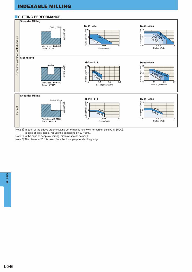
L046
MIL
LIN
GINDEXABLE MILLING
10
5 fz=0.1fz=0.150 0.5D1 D1
a
fz=0.1fz=0.15
fz=0.2fz=0.25
10
5
0 0.5D1 D1
a
D1
fz=0.15
10
5
0 0.5D1 D1
a
fz=0.15
10
5
0 0.5D1 D1
a&10─&14 &16─&100
D1=ø12─ø14D1=ø10
10
5
0 0.1 0.2 0.3
a
D1=ø50─ø100
D1=ø25─ø40D1=ø16─ø22
10
5
0 0.1 0.2 0.3
a
&10─&14 &16─&100
&10─&14 &16─&100
fz=0.1fz=0.1
y
Cutting Width
Cut
ting
Dep
th ( m
m)
Cut
ting
Dep
th ( m
m)
Cut
ting
Dep
th ( m
m)
Cut
ting
Dep
th ( m
m)
Cutting Width
Shoulder Milling
Slot Milling
Workpiece : JIS S50CGrade : UTi20T
Cutting Width
Cut
ting
Dep
thC
uttin
g D
epth
Workpiece : JIS S50CGrade : UTi20T
Cem
ente
d ca
rbid
e/C
oate
d ca
rbid
e
Feed fz (mm/tooth) Feed fz (mm/tooth)C
uttin
g D
epth
( mm
)
Cut
ting
Dep
th ( m
m)
Cut
ting
Dep
th
Cutting Width Cutting Width
Shoulder MillingCutting Width
Workpiece : JIS S50CGrade : NX2525
Cer
met
(Note 1) In each of the adove graphs cutting performance is shown for carbon steel (JIS S50C). In case of alloy steels, reduce the conditions by 20─30%.(Note 2) In the case of deep slot milling, air blow should be used.(Note 3) The diameter "D1" is taken from the tools peripheral cutting edge.
CUTTING PERFORMANCE
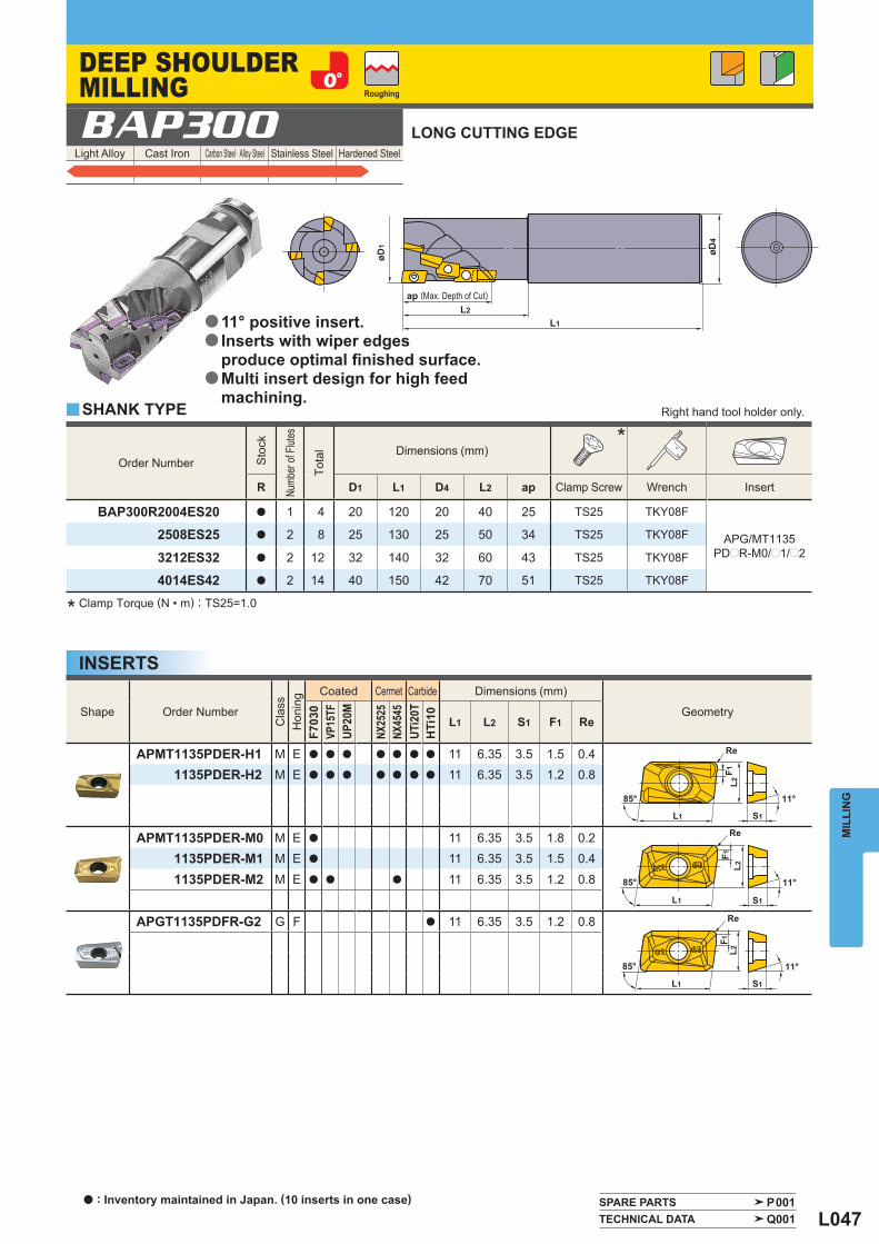
L047
Light Alloy Cast Iron Carbon Steel · Alloy Steel Stainless Steel Hardened Steel
SPARE PARTS P001 TECHNICAL DATA Q001
Order Number
Sto
ck
Numb
er of
Flut
es
Tota
l
Dimensions (mm)*
R D1 L1 D4 L2 ap Clamp Screw Wrench Insert
BAP300R2004ES20 a 1 4 20 120 20 40 25 TS25 TKY08F
APG/MT1135PDpR-M0/p1/p2
2508ES25 a 2 8 25 130 25 50 34 TS25 TKY08F
3212ES32 a 2 12 32 140 32 60 43 TS25 TKY08F
4014ES42 a 2 14 40 150 42 70 51 TS25 TKY08F
BAP300
y
Shape Order Number
Cla
ss
Hon
ing
Coated Cermet Carbide Dimensions (mm)
Geometry
F703
0VP
15TF
UP20
M
NX25
25NX
4545
UTi2
0TH
Ti10 L1 L2 S1 F1 Re
APMT1135PDER-H1 M E a a a a a a a 11 6.35 3.5 1.5 0.41135PDER-H2 M E a a a a a a a 11 6.35 3.5 1.2 0.8
APMT1135PDER-M0 M E a 11 6.35 3.5 1.8 0.21135PDER-M1 M E a 11 6.35 3.5 1.5 0.4
1135PDER-M2 M E a a a 11 6.35 3.5 1.2 0.8
APGT1135PDFR-G2 G F a 11 6.35 3.5 1.2 0.8
MIL
LIN
G
LONG CUTTING EDGE
* Clamp Torque (N • m) : TS25=1.0
SHANK TYPE Right hand tool holder only.
DEEP SHOULDER MILLING Roughing
ap (Max. Depth of Cut)
11° positive insert.Inserts with wiper edges produce optimal fi nished surface. Multi insert design for high feed machining.
a
a
a
INSERTS
a : Inventory maintained in Japan. (10 inserts in one case)
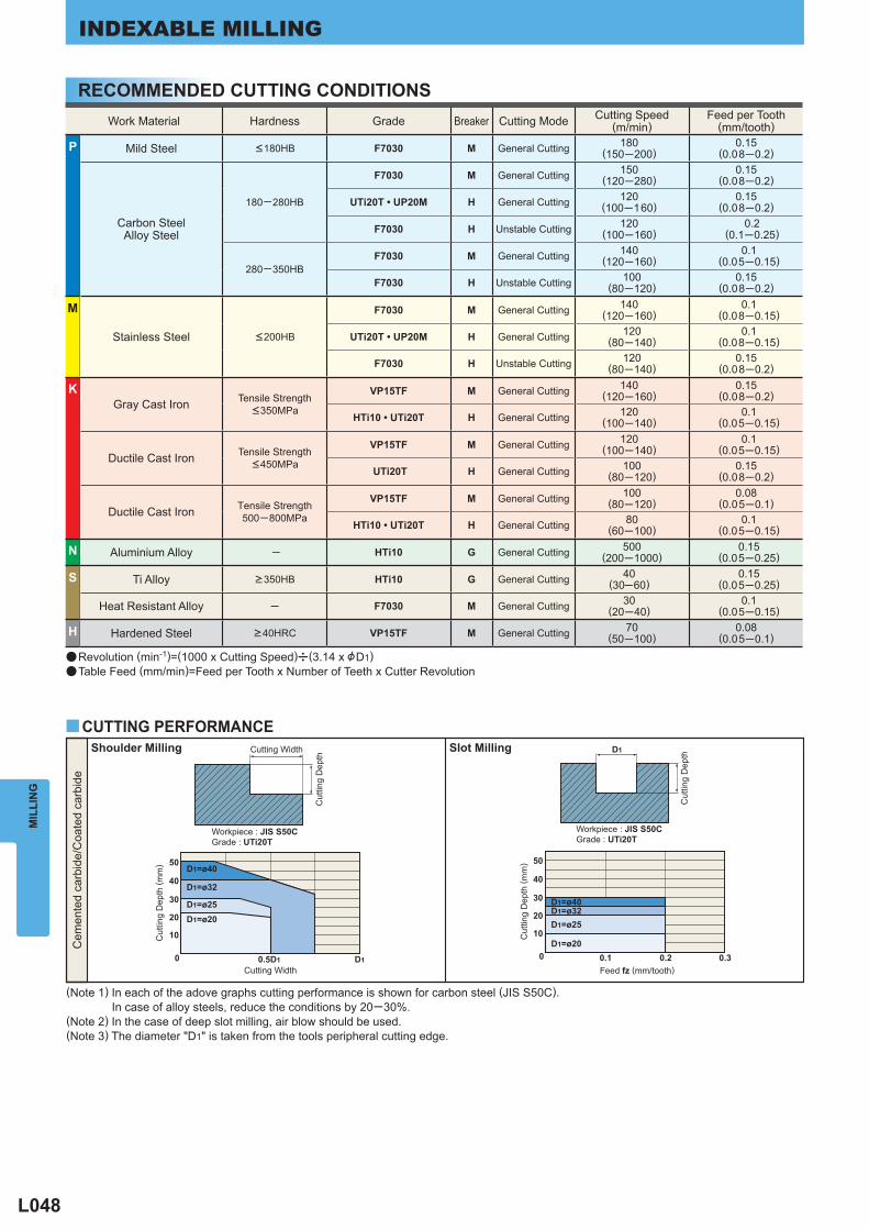
L048
Work Material Hardness Grade Breaker Cutting Mode Cutting Speed(m/min)
Feed per Tooth(mm/tooth)
P Mild Steel <180HB F7030 M General Cutting 180(150─200)
0.15(0.08─0.2)
Carbon SteelAlloy Steel
180─280HB
F7030 M General Cutting 150(120─280)
0.15(0.08─0.2)
UTi20T • UP20M H General Cutting 120(100─160)
0.15(0.08─0.2)
F7030 H Unstable Cutting 120(100─160)
0.2(0.1─0.25)
280─350HB F7030 M General Cutting 140
(120─160)0.1
(0.05─0.15)
F7030 H Unstable Cutting 100(80─120)
0.15(0.08─0.2)
M
Stainless Steel <200HB
F7030 M General Cutting 140(120─160)
0.1(0.08─0.15)
UTi20T • UP20M H General Cutting 120(80─140)
0.1(0.08─0.15)
F7030 H Unstable Cutting 120(80─140)
0.15(0.08─0.2)
K Gray Cast Iron Tensile Strength
<350MPa
VP15TF M General Cutting 140(120─160)
0.15(0.08─0.2)
HTi10 • UTi20T H General Cutting 120(100─140)
0.1(0.05─0.15)
Ductile Cast Iron Tensile Strength<450MPa
VP15TF M General Cutting 120(100─140)
0.1(0.05─0.15)
UTi20T H General Cutting 100(80─120)
0.15(0.08─0.2)
Ductile Cast Iron Tensile Strength500─800MPa
VP15TF M General Cutting 100(80─120)
0.08(0.05─0.1)
HTi10 • UTi20T H General Cutting 80(60─100)
0.1(0.05─0.15)
N Aluminium Alloy ─ HTi10 G General Cutting 500(200─1000)
0.15(0.05─0.25)
S Ti Alloy >350HB HTi10 G General Cutting 40(30─60)
0.15(0.05─0.25)
Heat Resistant Alloy ─ F7030 M General Cutting 30(20─40)
0.1(0.05─0.15)
H Hardened Steel >40HRC VP15TF M General Cutting 70(50─100)
0.08(0.05─0.1)
MIL
LIN
GINDEXABLE MILLING
RECOMMENDED CUTTING CONDITIONS
a Revolution (min-1)=(1000 x Cutting Speed)u(3.14 x &D1)a Table Feed (mm/min)=Feed per Tooth x Number of Teeth x Cutter Revolution
50
40
30
20
10
0
D1=ø40
D1=ø32
D1=ø25D1=ø20
0.5D1 D1
50
40
30
20
10
0
D1
D1=ø40D1=ø32D1=ø25
D1=ø200.1 0.2 0.3
yCUTTING PERFORMANCECutting Width
Cut
ting
Dep
th
Cut
ting
Dep
th ( m
m)
Shoulder Milling
Workpiece : JIS S50CGrade : UTi20T
Cutting Width
Slot Milling
Cut
ting
Dep
th
Cut
ting
Dep
th ( m
m)
Cem
ente
d ca
rbid
e/C
oate
d ca
rbid
e
(Note 1) In each of the adove graphs cutting performance is shown for carbon steel (JIS S50C). In case of alloy steels, reduce the conditions by 20─30%.(Note 2) In the case of deep slot milling, air blow should be used.(Note 3) The diameter "D1" is taken from the tools peripheral cutting edge.
Workpiece : JIS S50CGrade : UTi20T
Feed fz (mm/tooth)
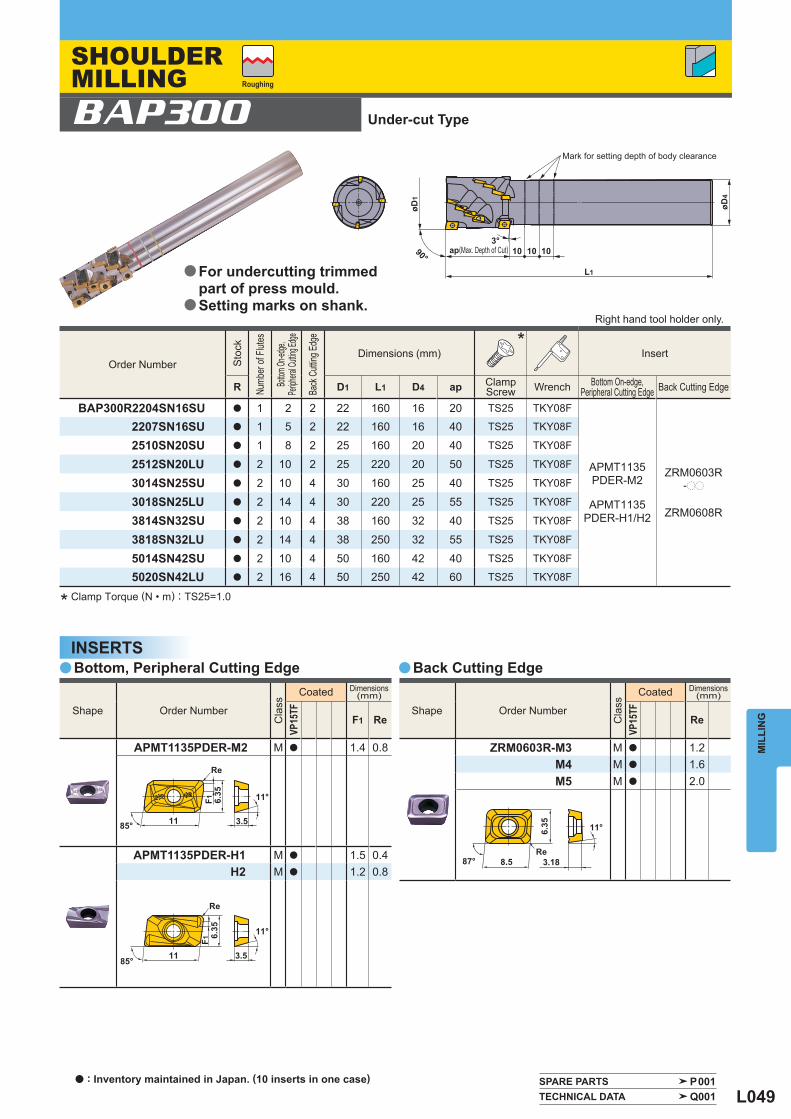
L049
Order Number
Sto
ck
Numb
er of
Flut
es
Bottom
On-ed
ge,
Periph
eral C
utting
Edge
Back
Cutt
ing Ed
ge
Dimensions (mm)*
Insert
R D1 L1 D4 ap Clamp Screw Wrench Bottom On-edge,
Peripheral Cutting Edge Back Cutting Edge
BAP300R2204SN16SU a 1 2 2 22 160 16 20 TS25 TKY08F
2207SN16SU a 1 5 2 22 160 16 40 TS25 TKY08F
2510SN20SU a 1 8 2 25 160 20 40 TS25 TKY08F
2512SN20LU a 2 10 2 25 220 20 50 TS25 TKY08F APMT1135PDER-M2
ZRM0603R-pp3014SN25SU a 2 10 4 30 160 25 40 TS25 TKY08F
3018SN25LU a 2 14 4 30 220 25 55 TS25 TKY08F APMT1135PDER-H1/H2 ZRM0608R
3814SN32SU a 2 10 4 38 160 32 40 TS25 TKY08F
3818SN32LU a 2 14 4 38 250 32 55 TS25 TKY08F
5014SN42SU a 2 10 4 50 160 42 40 TS25 TKY08F
5020SN42LU a 2 16 4 50 250 42 60 TS25 TKY08F
Shape Order Number
Cla
ss
Coated Dimensions(mm)
VP15
TF
F1 Re
APMT1135PDER-M2 M a 1.4 0.8
APMT1135PDER-H1 M a 1.5 0.4H2 M a 1.2 0.8
Shape Order Number
Cla
ss
Coated Dimensions(mm)
VP15
TF
Re
ZRM0603R-M3 M a 1.2M4 M a 1.6M5 M a 2.0
BAP300
a a
SPARE PARTS P001 TECHNICAL DATA Q001
MIL
LIN
G
Bottom, Peripheral Cutting Edge Back Cutting Edge
* Clamp Torque (N • m) : TS25=1.0
Mark for setting depth of body clearance
INSERTS
Right hand tool holder only.
SHOULDER MILLING Roughing
(Max. Depth of Cut)
Under-cut Type
For undercutting trimmed part of press mould.Setting marks on shank.
a
a
a : Inventory maintained in Japan. (10 inserts in one case)
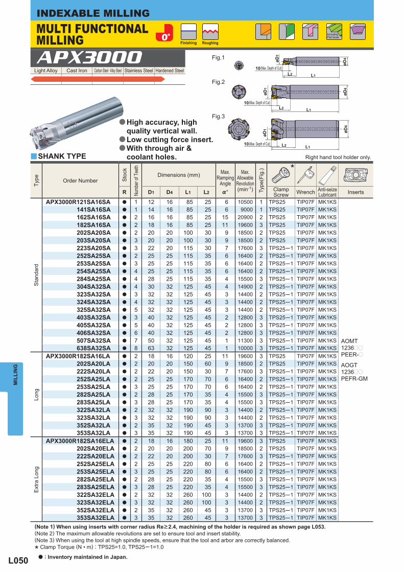
L050
Light Alloy Cast Iron Carbon Steel · Alloy Steel Stainless Steel Hardened Steel APX3000
Type
Order Number
Sto
ck
Numb
er of
Tee
th
Dimensions (mm) Max.
RampingAngle
Max.
AllowableRevolution(min-1)
Type
(Fig
.)
*
R D1 D4 L1 L2 %° ClampScrew Wrench Anti-seize
Lubricant Inserts
Sta
ndar
d
APX3000R121SA16SA a 1 12 16 85 25 6 10500 1 TPS25 TIP07F MK1KS
AOMT1236pp
PEER-p
AOGT1236pp
PEFR-GM
141SA16SA a 1 14 16 85 25 6 9000 1 TPS25 TIP07F MK1KS 162SA16SA a 2 16 16 85 25 15 20900 2 TPS25 TIP07F MK1KS 182SA16SA a 2 18 16 85 25 11 19600 3 TPS25 TIP07F MK1KS 202SA20SA a 2 20 20 100 30 9 18500 2 TPS25 TIP07F MK1KS 203SA20SA a 3 20 20 100 30 9 18500 2 TPS25 TIP07F MK1KS 223SA20SA a 3 22 20 115 30 7 17600 3 TPS25─1 TIP07F MK1KS 252SA25SA a 2 25 25 115 35 6 16400 2 TPS25─1 TIP07F MK1KS 253SA25SA a 3 25 25 115 35 6 16400 2 TPS25─1 TIP07F MK1KS 254SA25SA a 4 25 25 115 35 6 16400 2 TPS25─1 TIP07F MK1KS 284SA25SA a 4 28 25 115 35 4 15500 3 TPS25─1 TIP07F MK1KS 304SA32SA a 4 30 32 125 45 4 14900 2 TPS25─1 TIP07F MK1KS 323SA32SA a 3 32 32 125 45 3 14400 2 TPS25─1 TIP07F MK1KS 324SA32SA a 4 32 32 125 45 3 14400 2 TPS25─1 TIP07F MK1KS 325SA32SA a 5 32 32 125 45 3 14400 2 TPS25─1 TIP07F MK1KS 403SA32SA a 3 40 32 125 45 2 12800 3 TPS25─1 TIP07F MK1KS 405SA32SA a 5 40 32 125 45 2 12800 3 TPS25─1 TIP07F MK1KS 406SA32SA a 6 40 32 125 45 2 12800 3 TPS25─1 TIP07F MK1KS 507SA32SA a 7 50 32 125 45 1 11300 3 TPS25─1 TIP07F MK1KS 638SA32SA a 8 63 32 125 45 1 10000 3 TPS25─1 TIP07F MK1KS
Long
APX3000R182SA16LA a 2 18 16 120 25 11 19600 3 TPS25 TIP07F MK1KS 202SA20LA a 2 20 20 150 60 9 18500 2 TPS25 TIP07F MK1KS 222SA20LA a 2 22 20 150 30 7 17600 3 TPS25─1 TIP07F MK1KS 252SA25LA a 2 25 25 170 70 6 16400 2 TPS25─1 TIP07F MK1KS 253SA25LA a 3 25 25 170 70 6 16400 2 TPS25─1 TIP07F MK1KS 282SA25LA a 2 28 25 170 35 4 15500 3 TPS25─1 TIP07F MK1KS 283SA25LA a 3 28 25 170 35 4 15500 3 TPS25─1 TIP07F MK1KS 322SA32LA a 2 32 32 190 90 3 14400 2 TPS25─1 TIP07F MK1KS 323SA32LA a 3 32 32 190 90 3 14400 2 TPS25─1 TIP07F MK1KS 352SA32LA a 2 35 32 190 45 3 13700 3 TPS25─1 TIP07F MK1KS 353SA32LA a 3 35 32 190 45 3 13700 3 TPS25─1 TIP07F MK1KS
Ext
ra L
ong
APX3000R182SA16ELA a 2 18 16 180 25 11 19600 3 TPS25 TIP07F MK1KS 202SA20ELA a 2 20 20 200 70 9 18500 2 TPS25 TIP07F MK1KS 222SA20ELA a 2 22 20 200 30 7 17600 3 TPS25─1 TIP07F MK1KS 252SA25ELA a 2 25 25 220 80 6 16400 2 TPS25─1 TIP07F MK1KS 253SA25ELA a 3 25 25 220 80 6 16400 2 TPS25─1 TIP07F MK1KS 282SA25ELA a 2 28 25 220 35 4 15500 3 TPS25─1 TIP07F MK1KS 283SA25ELA a 3 28 25 220 35 4 15500 3 TPS25─1 TIP07F MK1KS 322SA32ELA a 2 32 32 260 100 3 14400 2 TPS25─1 TIP07F MK1KS 323SA32ELA a 3 32 32 260 100 3 14400 2 TPS25─1 TIP07F MK1KS 352SA32ELA a 2 35 32 260 45 3 13700 3 TPS25─1 TIP07F MK1KS 353SA32ELA a 3 35 32 260 45 3 13700 3 TPS25─1 TIP07F MK1KS
y
øD4
L1
øD1
øD4
L1
øD1
L2
L1
øD1 øD
4
L2
10
10
10
L2
MIL
LIN
GINDEXABLE MILLING
(Note 1) When using inserts with corner radius Re>2.4, machining of the holder is required as shown page L053.(Note 2) The maximum allowable revolutions are set to ensure tool and insert stability.(Note 3) When using the tool at high spindle speeds, ensure that the tool and arbor are correctly balanced.
* Clamp Torque (N • m) : TPS25=1.0, TPS25─1=1.0
SHANK TYPE Right hand tool holder only.
MULTI FUNCTIONAL MILLING Finishing Roughing
Including Flat faces
Fig.1
Fig.2
Fig.3
(Max. Depth of Cut)
(Max. Depth of Cut)
(Max. Depth of Cut)
High accuracy, high quality vertical wall.Low cutting force insert.With through air & coolant holes.
a
a
a
a : Inventory maintained in Japan.
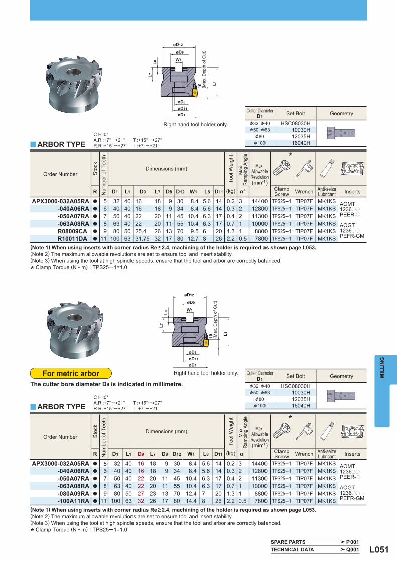
L051
Order Number
Sto
ck
Num
ber o
f Tee
th
Dimensions (mm)
Tool
Wei
ght
Max
.R
ampi
ng A
ngle
Max.
AllowableRevolution(min-1)
*
R D1 L1 D9 L7 D8 D12 W1 L8 D11 (kg) %° ClampScrew Wrench Anti-seize
Lubricant Inserts
APX3000-032A05RA a 5 32 40 16 18 9 30 8.4 5.6 14 0.2 3 14400 TPS25─1 TIP07F MK1KS AOMT1236pp
PEER-p
AOGT1236pp
PEFR-GM
-040A06RA a 6 40 40 16 18 9 34 8.4 5.6 14 0.3 2 12800 TPS25─1 TIP07F MK1KS -050A07RA a 7 50 40 22 20 11 45 10.4 6.3 17 0.4 2 11300 TPS25─1 TIP07F MK1KS -063A08RA a 8 63 40 22 20 11 55 10.4 6.3 17 0.7 1 10000 TPS25─1 TIP07F MK1KS R08009CA a 9 80 50 25.4 26 13 70 9.5 6 20 1.3 1 8800 TPS25─1 TIP07F MK1KS R10011DA a 11 100 63 31.75 32 17 80 12.7 8 26 2.2 0.5 7800 TPS25─1 TIP07F MK1KS
Cutter Diameter D1 Set Bolt Geometry
&32, &40 HSC08030H&50, &63 10030H
&80 12035H&100 16040H
Order Number
Sto
ck
Num
ber o
f Tee
th
Dimensions (mm)
Tool
Wei
ght
Max
.R
ampi
ng A
ngle
Max.
AllowableRevolution(min-1)
*
R D1 L1 D9 L7 D8 D12 W1 L8 D11 (kg) %° ClampScrew Wrench Anti-seize
Lubricant Inserts
APX3000-032A05RA a 5 32 40 16 18 9 30 8.4 5.6 14 0.2 3 14400 TPS25─1 TIP07F MK1KS AOMT1236pp
PEER-p
AOGT1236pp
PEFR-GM
-040A06RA a 6 40 40 16 18 9 34 8.4 5.6 14 0.3 2 12800 TPS25─1 TIP07F MK1KS -050A07RA a 7 50 40 22 20 11 45 10.4 6.3 17 0.4 2 11300 TPS25─1 TIP07F MK1KS -063A08RA a 8 63 40 22 20 11 55 10.4 6.3 17 0.7 1 10000 TPS25─1 TIP07F MK1KS -080A09RA a 9 80 50 27 23 13 70 12.4 7 20 1.3 1 8800 TPS25─1 TIP07F MK1KS -100A11RA a 11 100 63 32 26 17 80 14.4 8 26 2.2 0.5 7800 TPS25─1 TIP07F MK1KS
Cutter Diameter D1 Set Bolt Geometry
&32, &40 HSC08030H&50, &63 10030H
&80 12035H&100 16040H
y
y
C H :0°A.R :+7°─+21°R.R :+15°─+27°
T :+15°─+27°I :+7°─+21°
C H :0°A.R :+7°─+21°R.R :+15°─+27°
T :+15°─+27°I :+7°─+21°
SPARE PARTS P001 TECHNICAL DATA Q001
øD8
øD11
øD12
øD9
W1
øD1
L1
L8L7
10
øD8
øD11
øD12
øD9
W1
øD1
L1
L8L7
10
MIL
LIN
G
(Note 1) When using inserts with corner radius Re>2.4, machining of the holder is required as shown page L053.(Note 2) The maximum allowable revolutions are set to ensure tool and insert stability.(Note 3) When using the tool at high spindle speeds, ensure that the tool and arbor are correctly balanced.
* Clamp Torque (N • m) : TPS25─1=1.0
For metric arborThe cutter bore diameter D9 is indicated in millimetre.
ARBOR TYPE
ARBOR TYPE
Right hand tool holder only.
Right hand tool holder only.
( Max
. Dep
th o
f Cut
)
( Max
. Dep
th o
f Cut
)
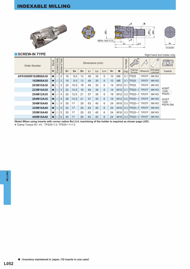
L052
y
Order Number
Sto
ck
Coo
lant
Hol
e
Numb
er of
Tee
th
Dimensions (mm)
Tool
Weig
ht
*
R D1 D4 D5 L1 L2 L11 H1 M ClampScrew Wrench Anti-seize
Lubricant Inserts (kg)
APX3000R162M08A30 a u 2 16 8.5 13 48 30 6 10 M8 0.1 TPS25 TIP07F MK1KS
AOMT1236pp
PEER-p
AOGT1236pp
PEFR-GM
182M08A30 a u 2 18 8.5 13 48 30 6 10 M8 0.1 TPS25 TIP07F MK1KS
203M10A30 a u 3 20 10.5 18 49 30 6 14 M10 0.1 TPS25 TIP07F MK1KS
223M10A30 a u 3 22 10.5 18 49 30 6 14 M10 0.1 TPS25─1 TIP07F MK1KS
254M12A35 a u 4 25 12.5 21 57 35 6 19 M12 0.2 TPS25─1 TIP07F MK1KS
284M12A35 a u 4 28 12.5 21 57 35 6 19 M12 0.2 TPS25─1 TIP07F MK1KS
304M16A40 a u 4 30 17 29 63 40 6 24 M16 0.3 TPS25─1 TIP07F MK1KS
325M16A40 a u 5 32 17 29 63 40 6 24 M16 0.3 TPS25─1 TIP07F MK1KS
355M16A40 a u 5 35 17 29 63 40 6 24 M16 0.3 TPS25─1 TIP07F MK1KS
406M16A40 a u 6 40 17 29 63 40 6 24 M16 0.3 TPS25─1 TIP07F MK1KS
L2 L11L1
10
øD4
øD5
MA
A
øD1
H1
MIL
LIN
GINDEXABLE MILLING
(Note) When using inserts with corner radius Re>2.4, machining of the holder is required as shown page L053.
* Clamp Torque (N • m) : TPS25=1.0, TPS25─1=1.0
SCREW-IN TYPE Right hand tool holder only.
A-A section
(Max. Depth of Cut)
a : Inventory maintained in Japan. (10 inserts in one case)
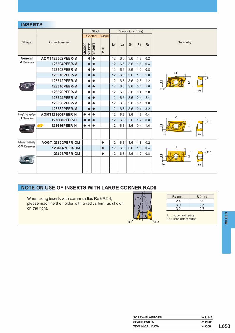
L053
Shape Order Number
Stock Dimensions (mm)
Geometry
Coated Carbide
L1 L2 S1 F1 Re
MC
5020
VP15
TFVP
20R
T
TF15
GeneralM Breaker
AOMT123602PEER-M a a 12 6.6 3.6 1.8 0.2123604PEER-M a a 12 6.6 3.6 1.6 0.4
123608PEER-M a a 12 6.6 3.6 1.2 0.8
123610PEER-M a a 12 6.6 3.6 1.0 1.0
123612PEER-M a a 12 6.6 3.6 0.8 1.2
123616PEER-M a a 12 6.6 3.6 0.4 1.6
123620PEER-M a a 12 6.6 3.6 0.4 2.0
123624PEER-M a a 12 6.6 3.6 0.4 2.4
123630PEER-M a a 12 6.6 3.6 0.4 3.0123632PEER-M a a 12 6.6 3.6 0.4 3.2
Strong Cutting Edge TypeH Breaker
AOMT123604PEER-H a a a 12 6.6 3.6 1.6 0.4123608PEER-H a a a 12 6.6 3.6 1.2 0.8
123616PEER-H a a a 12 6.6 3.6 0.4 1.6
For Machining of Aluminium AlloysGM Breaker
AOGT123602PEFR-GM a 12 6.6 3.6 1.8 0.2123604PEFR-GM a 12 6.6 3.6 1.6 0.4
123608PEFR-GM a 12 6.6 3.6 1.2 0.8
SCREW-IN ARBORS L147 SPARE PARTS P001 TECHNICAL DATA Q001
Re (mm) R (mm)2.4 1.93.0 2.53.2 2.7
ReR
S1
11°
F1 L2
Re
L1
S1
11°
F1 L2
Re
L1
11°
S1
F1 L2
Re
L1
MIL
LIN
G
INSERTS
NOTE ON USE OF INSERTS WITH LARGE CORNER RADII
When using inserts with corner radius Re>R2.4, please machine the holder with a radius form as shown on the right.
R : Holder end radiusRe : Insert corner radius
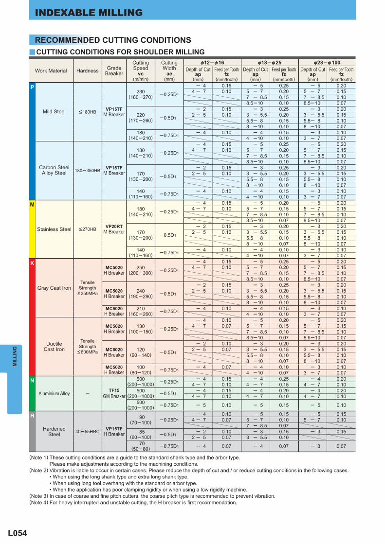
L054
y
Work Material Hardness GradeBreaker
CuttingSpeed
vc(m/min)
CuttingWidth
ae(mm)
&12─&16 &18─&25 &28─&100 Depth of Cut
ap(mm)
Feed per Tooth fz
(mm/tooth)
Depth of Cut ap
(mm)
Feed per Tooth fz
(mm/tooth)
Depth of Cut ap
(mm)
Feed per Tooth fz
(mm/tooth)
P
Mild Steel <180HB VP15TF M Breaker
230(180─270) ─0.25D1
─ 4 0.15 ─ 5 0.25 ─ 5 0.204 ─ 7 0.10 5 ─ 7 0.20 5 ─ 7 0.15
7 ─ 8.5 0.15 7 ─ 8.5 0.108.5─10 0.10 8.5─10 0.07
220(170─260) ─0.5D1
─ 2 0.15 ─ 3 0.25 ─ 3 0.202 ─ 5 0.10 3 ─ 5.5 0.20 3 ─ 5.5 0.15
5.5─ 8 0.15 5.5─ 8 0.108 ─10 0.10 8 ─10 0.07
180(140─210) ─0.75D1
─ 4 0.10 ─ 4 0.15 ─ 3 0.104 ─10 0.10 3 ─ 7 0.07
Carbon SteelAlloy Steel 180─350HB VP15TF
M Breaker
180(140─210) ─0.25D1
─ 4 0.15 ─ 5 0.25 ─ 5 0.204 ─ 7 0.10 5 ─ 7 0.20 5 ─ 7 0.15
7 ─ 8.5 0.15 7 ─ 8.5 0.108.5─10 0.10 8.5─10 0.07
170(130─200) ─0.5D1
─ 2 0.15 ─ 3 0.25 ─ 3 0.202 ─ 5 0.10 3 ─ 5.5 0.20 3 ─ 5.5 0.15
5.5─ 8 0.15 5.5─ 8 0.108 ─10 0.10 8 ─10 0.07
140(110─160) ─0.75D1
─ 4 0.10 ─ 4 0.15 ─ 3 0.104 ─10 0.10 3 ─ 7 0.07
M
Stainless Steel <270HB VP20RT M Breaker
180(140─210) ─0.25D1
─ 4 0.15 ─ 5 0.20 ─ 5 0.204 ─ 7 0.10 5 ─ 7 0.15 5 ─ 7 0.15
7 ─ 8.5 0.10 7 ─ 8.5 0.108.5─10 0.07 8.5─10 0.07
170(130─200) ─0.5D1
─ 2 0.15 ─ 3 0.20 ─ 3 0.202 ─ 5 0.10 3 ─ 5.5 0.15 3 ─ 5.5 0.15
5.5─ 8 0.10 5.5─ 8 0.108 ─10 0.07 8 ─10 0.07
140(110─160) ─0.75D1
─ 4 0.10 ─ 4 0.10 ─ 3 0.104 ─10 0.07 3 ─ 7 0.07
K
Gray Cast Iron Tensile
Strength <350MPa
MC5020 H Breaker
250(200─300) ─0.25D1
─ 4 0.15 ─ 5 0.25 ─ 5 0.204 ─ 7 0.10 5 ─ 7 0.20 5 ─ 7 0.15
7 ─ 8.5 0.15 7 ─ 8.5 0.10 8.5─10 0.10 8.5─10 0.07
MC5020 H Breaker
240(190─290) ─0.5D1
─ 2 0.15 ─ 3 0.25 ─ 3 0.202 ─ 5 0.10 3 ─ 5.5 0.20 3 ─ 5.5 0.15
5.5─ 8 0.15 5.5─ 8 0.108 ─10 0.10 8 ─10 0.07
MC5020 H Breaker
210(160─260) ─0.75D1
─ 4 0.10 ─ 4 0.15 ─ 3 0.104 ─10 0.10 3 ─ 7 0.07
DuctileCast Iron
TensileStrength <800MPa
MC5020 H Breaker
130(100─150) ─0.25D1
─ 4 0.10 ─ 5 0.20 ─ 5 0.204 ─ 7 0.07 5 ─ 7 0.15 5 ─ 7 0.15
7 ─ 8.5 0.10 7 ─ 8.5 0.108.5─10 0.07 8.5─10 0.07
MC5020 H Breaker
120(90─140) ─0.5D1
─ 2 0.10 ─ 3 0.20 ─ 3 0.202 ─ 5 0.07 3 ─ 5.5 0.15 3 ─ 5.5 0.15
5.5─ 8 0.10 5.5─ 8 0.108 ─10 0.07 8 ─10 0.07
MC5020 H Breaker
100(80─120) ─0.75D1
─ 4 0.07 ─ 4 0.10 ─ 3 0.104 ─10 0.07 3 ─ 7 0.07
N
Aluminium Alloy ─ TF15 GM Breaker
500(200─1000) ─0.25D1
─ 4 0.15 ─ 4 0.25 ─ 4 0.204 ─ 7 0.10 4 ─ 7 0.15 4 ─ 7 0.10
500(200─1000) ─0.5D1 ─ 4 0.15 ─ 4 0.20 ─ 4 0.20
4 ─ 7 0.10 4 ─ 7 0.10 4 ─ 7 0.10500
(200─1000) ─0.75D1 ─ 5 0.10 ─ 5 0.15 ─ 5 0.10
H
HardenedSteel 40─55HRC VP15TF
H Breaker
90(70─100) ─0.25D1
─ 4 0.10 ─ 5 0.15 ─ 5 0.154 ─ 7 0.07 5 ─ 7 0.10 5 ─ 7 0.10
7 ─ 8.5 0.07 85
(60─100) ─0.5D1─ 2 0.10 ─ 3 0.15 ─ 3 0.15
2 ─ 5 0.07 3 ─ 5.5 0.10 70
(50─80) ─0.75D1 ─ 4 0.07 ─ 4 0.07 ─ 3 0.07
MIL
LIN
GINDEXABLE MILLING
(Note 1) These cutting conditions are a guide to the standard shank type and the arbor type. Please make adjustments according to the machining conditions.(Note 2) Vibration is liable to occur in certain cases. Please reduce the depth of cut and / or reduce cutting conditions in the following cases. • When using the long shank type and extra long shank type. • When using long tool overhang with the standard or arbor type. • When the application has poor clamping rigidity or when using a low rigidity machine.(Note 3) In case of coarse and fi ne pitch cutters, the coarse pitch type is recommended to prevent vibration.(Note 4) For heavy interrupted and unstable cutting, the H breaker is fi rst recommendation.
RECOMMENDED CUTTING CONDITIONSCUTTING CONDITIONS FOR SHOULDER MILLING
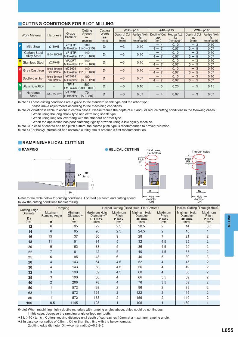
L055
Work Material Hardness GradeBreaker
CuttingSpeed
vc(m/min)
CuttingWidth
ae(mm)
&12─&16 &18─&25 &28─&100 Depth of Cut
ap(mm)
Feed per Tooth fz
(mm/tooth)
Depth of Cut ap
(mm)
Feed per Tooth fz
(mm/tooth)
Depth of Cut ap
(mm)
Feed per Tooth fz
(mm/tooth)
P Mild Steel <180HB VP15TF
M Breaker 180
(140─210) D1 ─3 0.10 ─ 4 0.10 ─ 3 0.10 4 ─ 7 0.07 3 ─ 5 0.07
Carbon SteelAlloy Steel 180─350HB
VP15TF M Breaker
140(110─160) D1 ─3 0.10 ─ 4 0.10 ─ 3 0.10
4 ─ 7 0.07 3 ─ 5 0.07M Stainless Steel <270HB
VP20RT M Breaker
140(110─160) D1 ─3 0.10 ─ 4 0.10 ─ 3 0.10
4 ─ 7 0.07 3 ─ 5 0.07K Gray Cast Iron Tensile Strength
<350MPaMC5020
M Breaker 140
(110─160) D1 ─3 0.10 ─ 4 0.10 ─ 3 0.10 4 ─ 7 0.07 3 ─ 5 0.07
Ductile Cast Iron Tensile Strength <800MPa
MC5020 M Breaker
100 (80─120) D1 ─3 0.07 ─ 4 0.10 ─ 3 0.10
4 ─ 7 0.07 3 ─ 5 0.07N Aluminium Alloy ─ TF15
GM Breaker 500
(200─1000) D1 ─5 0.10 ─ 5 0.20 ─ 5 0.15
H HardenedSteel 40─55HRC
VP15TF H Breaker
70(50─80) D1 ─3 0.07 ─ 4 0.07 ─ 3 0.07
a a
y
y
Cutting EdgeDiameter
D1(mm)
Ramping Helical Cutting (Blind Hole, Flat Bottom) Helical Cutting (Through Hole)
Maximum
Ramping Angle
%°
MinimumDistance
L(mm)
Maximum Hole
DiameterDH max.
(mm)
MaximumPitch
P max.(mm)
Minimum Hole
DiameterDH min.
(mm)
MaximumPitch
P max.(mm)
Minimum Hole
DiameterDH min.
(mm)
MaximumPitch
P max.(mm)
12 6 95 22 2.5 20.5 2 14 0.514 6 95 26 2.5 24.5 2 18 116 15 37 30 9 28 7 21 218 11 51 34 5 32 4.5 25 220 9 63 38 5 36 4.5 29 222 7 81 42 5 40 4.5 33 225 6 95 48 6 46 5 39 328 4 143 54 4.5 52 4 45 230 4 143 58 4.5 56 4 49 232 3 190 62 4.5 60 4 53 235 3 190 68 4 66 3.5 59 240 2 286 78 4 76 3.5 69 250 1 572 98 2 96 2 89 263 1 572 124 2 122 2 115 280 1 572 158 2 156 2 149 2
100 0.5 1145 198 1 196 1 189 1
%°
D1
ap
D1 D1
L
tan%
apL=
MIL
LIN
G
Blind holes,Flat bottom Through holes
Refer to the table below for cutting conditions. For feed per tooth and cutting speed, follow the cutting conditions for slot milling.
(Note) When machining highly ductile materials with ramping angles above, chips could be continuous. In this case, decrease the ramping angle or feed per tooth.
*1 L (=10 / tan %). Cutters' moving distance until depth of cut reaches 10mm at a maximum ramping angle.
*2 In case corner radius of 0.8mm. Other than that, fi nd with the below formula. {(cutting edge diameter D1)─ (corner radius)─0.2)}×2
Pitch(P)
Holediameter
(DH)
CUTTING CONDITIONS FOR SLOT MILLING
(Note 1) These cutting conditions are a guide to the standard shank type and the arbor type. Please make adjustments according to the machining conditions.(Note 2) Vibration is liable to occur in certain cases. Please reduce the depth of cut and / or reduce cutting conditions in the following cases. • When using the long shank type and extra long shank type. • When using long tool overhang with the standard or arbor type. • When the application has poor clamping rigidity or when using a low rigidity machine.(Note 3) In case of coarse and fi ne pitch cutters, the coarse pitch type is recommended to prevent vibration.(Note 4) For heavy interrupted and unstable cutting, the H breaker is fi rst recommendation.
RAMPING/HELICAL CUTTINGRAMPING HELICAL CUTTING
Pitch(P)
Holediameter
(DH)
*1 *2
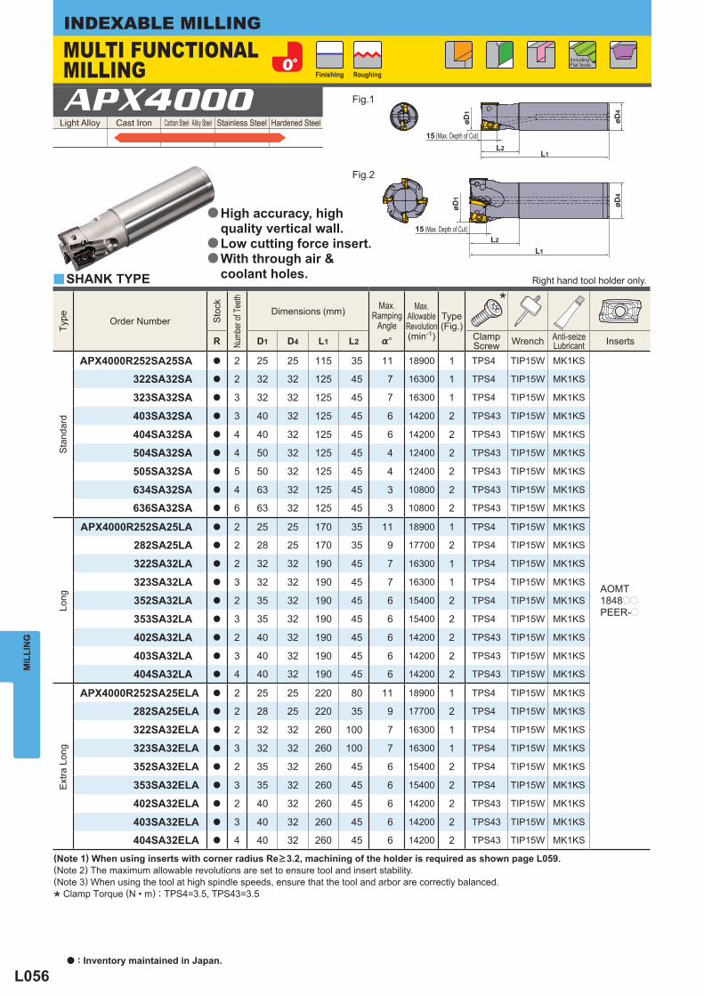
L056
Light Alloy Cast Iron Carbon Steel · Alloy Steel Stainless Steel Hardened Steel APX4000
Type
Order Number
Sto
ck
Numb
er of
Tee
th
Dimensions (mm) Max.
RampingAngle
Max.
AllowableRevolution(min-1)
Type(Fig.)
*
R D1 D4 L1 L2 %° ClampScrew Wrench Anti-seize
Lubricant Inserts
Sta
ndar
d
APX4000R252SA25SA a 2 25 25 115 35 11 18900 1 TPS4 TIP15W MK1KS
AOMT1848pp
PEER-p
322SA32SA a 2 32 32 125 45 7 16300 1 TPS4 TIP15W MK1KS
323SA32SA a 3 32 32 125 45 7 16300 1 TPS4 TIP15W MK1KS
403SA32SA a 3 40 32 125 45 6 14200 2 TPS43 TIP15W MK1KS
404SA32SA a 4 40 32 125 45 6 14200 2 TPS43 TIP15W MK1KS
504SA32SA a 4 50 32 125 45 4 12400 2 TPS43 TIP15W MK1KS
505SA32SA a 5 50 32 125 45 4 12400 2 TPS43 TIP15W MK1KS
634SA32SA a 4 63 32 125 45 3 10800 2 TPS43 TIP15W MK1KS
636SA32SA a 6 63 32 125 45 3 10800 2 TPS43 TIP15W MK1KS
Long
APX4000R252SA25LA a 2 25 25 170 35 11 18900 1 TPS4 TIP15W MK1KS
282SA25LA a 2 28 25 170 35 9 17700 2 TPS4 TIP15W MK1KS
322SA32LA a 2 32 32 190 45 7 16300 1 TPS4 TIP15W MK1KS
323SA32LA a 3 32 32 190 45 7 16300 1 TPS4 TIP15W MK1KS
352SA32LA a 2 35 32 190 45 6 15400 2 TPS4 TIP15W MK1KS
353SA32LA a 3 35 32 190 45 6 15400 2 TPS4 TIP15W MK1KS
402SA32LA a 2 40 32 190 45 6 14200 2 TPS43 TIP15W MK1KS
403SA32LA a 3 40 32 190 45 6 14200 2 TPS43 TIP15W MK1KS
404SA32LA a 4 40 32 190 45 6 14200 2 TPS43 TIP15W MK1KS
Ext
ra L
ong
APX4000R252SA25ELA a 2 25 25 220 80 11 18900 1 TPS4 TIP15W MK1KS
282SA25ELA a 2 28 25 220 35 9 17700 2 TPS4 TIP15W MK1KS
322SA32ELA a 2 32 32 260 100 7 16300 1 TPS4 TIP15W MK1KS
323SA32ELA a 3 32 32 260 100 7 16300 1 TPS4 TIP15W MK1KS
352SA32ELA a 2 35 32 260 45 6 15400 2 TPS4 TIP15W MK1KS
353SA32ELA a 3 35 32 260 45 6 15400 2 TPS4 TIP15W MK1KS
402SA32ELA a 2 40 32 260 45 6 14200 2 TPS43 TIP15W MK1KS
403SA32ELA a 3 40 32 260 45 6 14200 2 TPS43 TIP15W MK1KS
404SA32ELA a 4 40 32 260 45 6 14200 2 TPS43 TIP15W MK1KS
y
øD4
øD4
øD1
øD1
L1
L1
L2
L2
15
15
MIL
LIN
GINDEXABLE MILLING
(Note 1) When using inserts with corner radius Re>3.2, machining of the holder is required as shown page L059.(Note 2) The maximum allowable revolutions are set to ensure tool and insert stability.(Note 3) When using the tool at high spindle speeds, ensure that the tool and arbor are correctly balanced.
* Clamp Torque (N • m) : TPS4=3.5, TPS43=3.5
SHANK TYPE Right hand tool holder only.
MULTI FUNCTIONAL MILLING Finishing Roughing
Including Flat faces
Fig.1
Fig.2
(Max. Depth of Cut)
(Max. Depth of Cut)
High accuracy, high quality vertical wall.Low cutting force insert.With through air & coolant holes.
a
a
a
a : Inventory maintained in Japan.
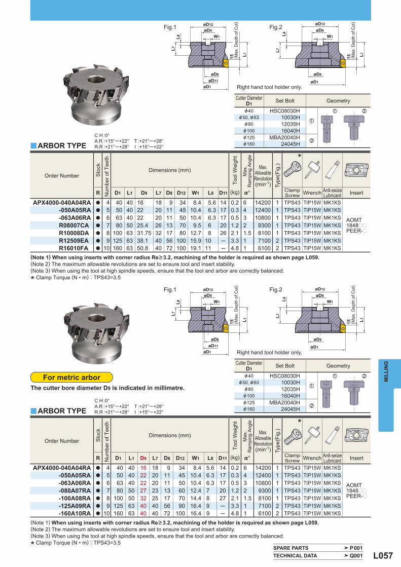
L057
Order Number
Sto
ck
Num
ber o
f Tee
th
Dimensions (mm)
Tool
Wei
ght
Max
.R
ampi
ng A
ngle
Max.
AllowableRevolution(min-1)
Type
(Fig
.)
*
R D1 L1 D9 L7 D8 D12 W1 L8 D11 (kg) %° ClampScrew Wrench Anti-seize
Lubricant Insert
APX4000-040A04RA a 4 40 40 16 18 9 34 8.4 5.6 14 0.2 6 14200 1 TPS43 TIP15W MK1KS
AOMT1848pp
PEER-p
-050A05RA a 5 50 40 22 20 11 45 10.4 6.3 17 0.3 4 12400 1 TPS43 TIP15W MK1KS-063A06RA a 6 63 40 22 20 11 50 10.4 6.3 17 0.5 3 10800 1 TPS43 TIP15W MK1KSR08007CA a 7 80 50 25.4 26 13 70 9.5 6 20 1.2 2 9300 1 TPS43 TIP15W MK1KSR10008DA a 8 100 63 31.75 32 17 80 12.7 8 26 2.1 1.5 8100 1 TPS43 TIP15W MK1KSR12509EA a 9 125 63 38.1 40 56 100 15.9 10 ─ 3.3 1 7100 2 TPS43 TIP15W MK1KSR16010FA a 10 160 63 50.8 40 72 100 19.1 11 ─ 4.8 1 6100 2 TPS43 TIP15W MK1KS
Order Number
Sto
ck
Num
ber o
f Tee
th
Dimensions (mm)
Tool
Wei
ght
Max
.R
ampi
ng A
ngle
Max.
AllowableRevolution(min-1)
Type
(Fig
.)
*
R D1 L1 D9 L7 D8 D12 W1 L8 D11 (kg) %° ClampScrew Wrench Anti-seize
Lubricant Insert
APX4000-040A04RA a 4 40 40 16 18 9 34 8.4 5.6 14 0.2 6 14200 1 TPS43 TIP15W MK1KS
AOMT1848pp
PEER-p
-050A05RA a 5 50 40 22 20 11 45 10.4 6.3 17 0.3 4 12400 1 TPS43 TIP15W MK1KS -063A06RA a 6 63 40 22 20 11 50 10.4 6.3 17 0.5 3 10800 1 TPS43 TIP15W MK1KS -080A07RA a 7 80 50 27 23 13 60 12.4 7 20 1.2 2 9300 1 TPS43 TIP15W MK1KS -100A08RA a 8 100 50 32 25 17 70 14.4 8 27 2.1 1.5 8100 1 TPS43 TIP15W MK1KS -125A09RA a 9 125 63 40 40 56 90 16.4 9 ─ 3.3 1 7100 2 TPS43 TIP15W MK1KS -160A10RA a 10 160 63 40 40 72 100 16.4 9 ─ 4.8 1 6100 2 TPS43 TIP15W MK1KS
Cutter Diameter D1 Set Bolt Geometry
&40 HSC08030H
z
z x&50, &63 10030H
&80 12035H&100 16040H&125 MBA20040H
x&160 24045H
Cutter Diameter D1 Set Bolt Geometry
&40 HSC08030H
z
z x&50, &63 10030H
&80 12035H&100 16040H&125 MBA20040H
x&160 24045H
y
y
C H :0°A.R :+15°─+22°R.R :+21°─+28°
T :+21°─+28°I :+15°─+22°
C H :0°A.R :+15°─+22°R.R :+21°─+28°
T :+21°─+28°I :+15°─+22°
SPARE PARTS P001 TECHNICAL DATA Q001
15
øD12
øD1øD1
øD12øD9
øD8øD8
øD11
øD9
W1W1
L1
L8L7L7
15 L1
L8
15
øD12
øD1øD1
øD12øD9
øD8øD8
øD11
øD9
W1W1
L1
L8L7L7
15 L1
L8
MIL
LIN
G
(Note 1) When using inserts with corner radius Re>3.2, machining of the holder is required as shown page L059.(Note 2) The maximum allowable revolutions are set to ensure tool and insert stability.(Note 3) When using the tool at high spindle speeds, ensure that the tool and arbor are correctly balanced.
* Clamp Torque (N • m) : TPS43=3.5
For metric arborThe cutter bore diameter D9 is indicated in millimetre.
ARBOR TYPE
ARBOR TYPE
Right hand tool holder only.
Right hand tool holder only.
Fig.1 Fig.2
Fig.1 Fig.2
( Max
. Dep
th o
f Cut
)
( Max
. Dep
th o
f Cut
)
( Max
. Dep
th o
f Cut
)
( Max
. Dep
th o
f Cut
)
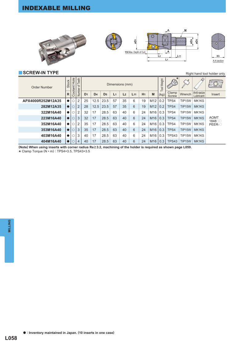
L058
Order Number
Sto
ck
Coo
lant
Hol
e
Numb
er of
Tee
th
Dimensions (mm)
Tool
Weig
ht
*
R D1 D4 D5 L1 L2 L11 H1 M ClampScrew Wrench Anti-seize
Lubricant Insert (kg)
APX4000R252M12A35 a u 2 25 12.5 23.5 57 35 6 19 M12 0.2 TPS4 TIP15W MK1KS
AOMT1848pp
PEER-p
282M12A35 a u 2 28 12.5 23.5 57 35 6 19 M12 0.2 TPS4 TIP15W MK1KS
322M16A40 a u 2 32 17 28.5 63 40 6 24 M16 0.3 TPS4 TIP15W MK1KS
223M16A40 a u 3 32 17 28.5 63 40 6 24 M16 0.3 TPS4 TIP15W MK1KS
352M16A40 a u 2 35 17 28.5 63 40 6 24 M16 0.3 TPS4 TIP15W MK1KS
353M16A40 a u 3 35 17 28.5 63 40 6 24 M16 0.3 TPS4 TIP15W MK1KS
403M16A40 a u 3 40 17 28.5 63 40 6 24 M16 0.3 TPS43 TIP15W MK1KS
404M16A40 a u 4 40 17 28.5 63 40 6 24 M16 0.3 TPS43 TIP15W MK1KS
y
øD4
øD5
M
L2 L11L1
A
A15
øD1
H1
MIL
LIN
GINDEXABLE MILLING
(Note) When using inserts with corner radius Re>3.2, machining of the holder is required as shown page L059.
* Clamp Torque (N • m) : TPS4=3.5, TPS43=3.5
SCREW-IN TYPE Right hand tool holder only.
A-A section
(Max. Depth of Cut)
a : Inventory maintained in Japan. (10 inserts in one case)
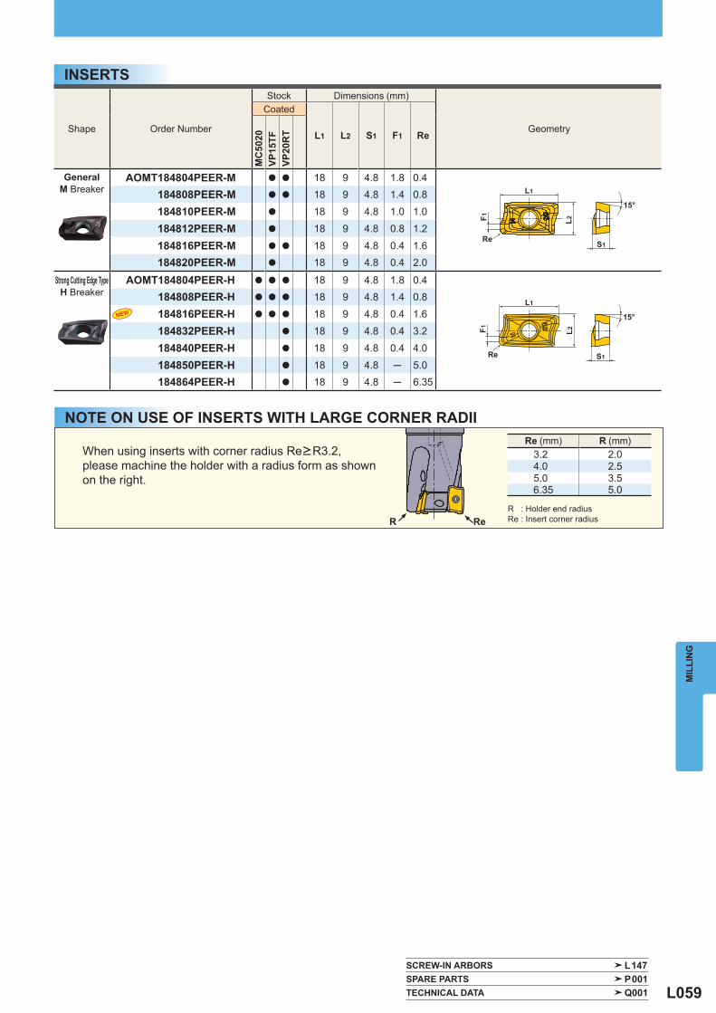
L059
Shape Order Number
Stock Dimensions (mm)
Geometry
Coated
L1 L2 S1 F1 Re
MC
5020
VP15
TFVP
20R
T
GeneralM Breaker
AOMT184804PEER-M a a 18 9 4.8 1.8 0.4184808PEER-M a a 18 9 4.8 1.4 0.8
184810PEER-M a 18 9 4.8 1.0 1.0
184812PEER-M a 18 9 4.8 0.8 1.2
184816PEER-M a a 18 9 4.8 0.4 1.6184820PEER-M a 18 9 4.8 0.4 2.0
Strong Cutting Edge TypeH Breaker
AOMT184804PEER-H a a a 18 9 4.8 1.8 0.4184808PEER-H a a a 18 9 4.8 1.4 0.8
184816PEER-H a a a 18 9 4.8 0.4 1.6
184832PEER-H a 18 9 4.8 0.4 3.2
184840PEER-H a 18 9 4.8 0.4 4.0
184850PEER-H a 18 9 4.8 ─ 5.0184864PEER-H a 18 9 4.8 ─ 6.35
SCREW-IN ARBORS L147 SPARE PARTS P001 TECHNICAL DATA Q001
Re (mm) R (mm)3.2 2.04.0 2.55.0 3.56.35 5.0
S1
15°
F1 L2
Re
L1
S1
15°
F1 L2
Re
L1
ReR
MIL
LIN
G
INSERTS
NOTE ON USE OF INSERTS WITH LARGE CORNER RADII
When using inserts with corner radius Re>R3.2, please machine the holder with a radius form as shown on the right.
R : Holder end radiusRe : Insert corner radius
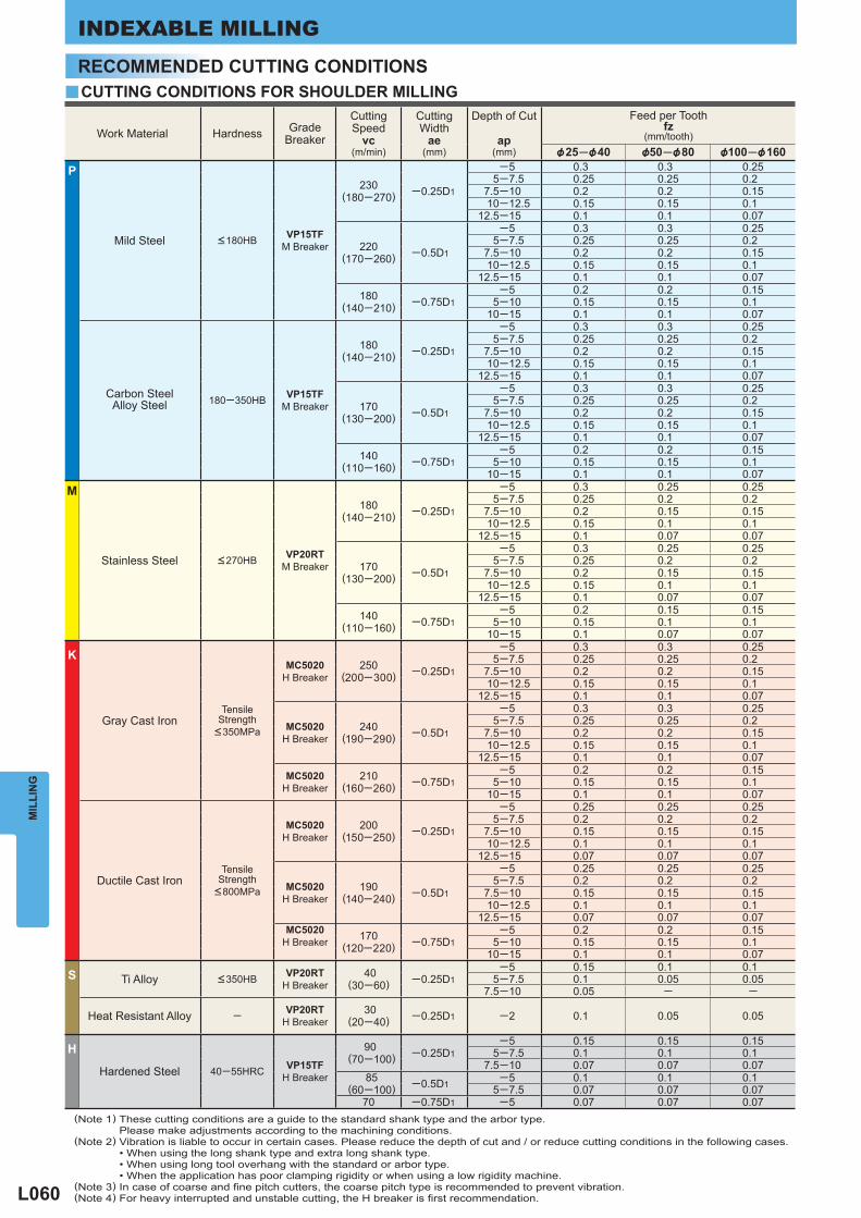
L060
y
Work Material Hardness GradeBreaker
CuttingSpeed
vc(m/min)
CuttingWidth
ae(mm)
Depth of Cut
ap(mm)
Feed per Tooth fz
(mm/tooth) &25─&40 &50─&80 &100─&160
P
Mild Steel <180HB VP15TF M Breaker
230(180─270) ─0.25D1
─5 0.3 0.3 0.255─7.5 0.25 0.25 0.2
7.5─10 0.2 0.2 0.1510─12.5 0.15 0.15 0.1
12.5─15 0.1 0.1 0.07
220(170─260) ─0.5D1
─5 0.3 0.3 0.255─7.5 0.25 0.25 0.2
7.5─10 0.2 0.2 0.1510─12.5 0.15 0.15 0.1
12.5─15 0.1 0.1 0.07
180(140─210) ─0.75D1
─5 0.2 0.2 0.155─10 0.15 0.15 0.1
10─15 0.1 0.1 0.07
Carbon SteelAlloy Steel 180─350HB VP15TF
M Breaker
180(140─210) ─0.25D1
─5 0.3 0.3 0.255─7.5 0.25 0.25 0.2
7.5─10 0.2 0.2 0.1510─12.5 0.15 0.15 0.1
12.5─15 0.1 0.1 0.07
170(130─200) ─0.5D1
─5 0.3 0.3 0.255─7.5 0.25 0.25 0.2
7.5─10 0.2 0.2 0.1510─12.5 0.15 0.15 0.1
12.5─15 0.1 0.1 0.07
140(110─160) ─0.75D1
─5 0.2 0.2 0.155─10 0.15 0.15 0.1
10─15 0.1 0.1 0.07M
Stainless Steel <270HB VP20RT M Breaker
180(140─210) ─0.25D1
─5 0.3 0.25 0.255─7.5 0.25 0.2 0.2
7.5─10 0.2 0.15 0.1510─12.5 0.15 0.1 0.1
12.5─15 0.1 0.07 0.07
170(130─200) ─0.5D1
─5 0.3 0.25 0.255─7.5 0.25 0.2 0.2
7.5─10 0.2 0.15 0.1510─12.5 0.15 0.1 0.1
12.5─15 0.1 0.07 0.07
140(110─160) ─0.75D1
─5 0.2 0.15 0.155─10 0.15 0.1 0.1
10─15 0.1 0.07 0.07
K
Gray Cast Iron Tensile
Strength <350MPa
MC5020 H Breaker
250(200─300) ─0.25D1
─5 0.3 0.3 0.255─7.5 0.25 0.25 0.2
7.5─10 0.2 0.2 0.1510─12.5 0.15 0.15 0.1
12.5─15 0.1 0.1 0.07
MC5020 H Breaker
240(190─290) ─0.5D1
─5 0.3 0.3 0.255─7.5 0.25 0.25 0.2
7.5─10 0.2 0.2 0.1510─12.5 0.15 0.15 0.1
12.5─15 0.1 0.1 0.07
MC5020 H Breaker
210(160─260) ─0.75D1
─5 0.2 0.2 0.155─10 0.15 0.15 0.1
10─15 0.1 0.1 0.07
Ductile Cast Iron Tensile
Strength <800MPa
MC5020 H Breaker
200(150─250) ─0.25D1
─5 0.25 0.25 0.255─7.5 0.2 0.2 0.2
7.5─10 0.15 0.15 0.1510─12.5 0.1 0.1 0.1
12.5─15 0.07 0.07 0.07
MC5020 H Breaker
190(140─240) ─0.5D1
─5 0.25 0.25 0.255─7.5 0.2 0.2 0.2
7.5─10 0.15 0.15 0.1510─12.5 0.1 0.1 0.1
12.5─15 0.07 0.07 0.07MC5020
H Breaker
170(120─220) ─0.75D1
─5 0.2 0.2 0.155─10 0.15 0.15 0.1
10─15 0.1 0.1 0.07
S Ti Alloy <350HB VP20RT H Breaker
40(30─60) ─0.25D1
─5 0.15 0.1 0.15─7.5 0.1 0.05 0.05
7.5─10 0.05 ─ ─
Heat Resistant Alloy ─ VP20RT H Breaker
30(20─40) ─0.25D1 ─2 0.1 0.05 0.05
H
Hardened Steel 40─55HRC VP15TF H Breaker
90 (70─100) ─0.25D1
─5 0.15 0.15 0.155─7.5 0.1 0.1 0.1
7.5─10 0.07 0.07 0.07 85
(60─100) ─0.5D1 ─5 0.1 0.1 0.15─7.5 0.07 0.07 0.07
70 ─0.75D1 ─5 0.07 0.07 0.07
MIL
LIN
GINDEXABLE MILLING
RECOMMENDED CUTTING CONDITIONS
(Note 1) These cutting conditions are a guide to the standard shank type and the arbor type. Please make adjustments according to the machining conditions.(Note 2) Vibration is liable to occur in certain cases. Please reduce the depth of cut and / or reduce cutting conditions in the following cases. • When using the long shank type and extra long shank type. • When using long tool overhang with the standard or arbor type. • When the application has poor clamping rigidity or when using a low rigidity machine.(Note 3) In case of coarse and fi ne pitch cutters, the coarse pitch type is recommended to prevent vibration.(Note 4) For heavy interrupted and unstable cutting, the H breaker is fi rst recommendation.
CUTTING CONDITIONS FOR SHOULDER MILLING
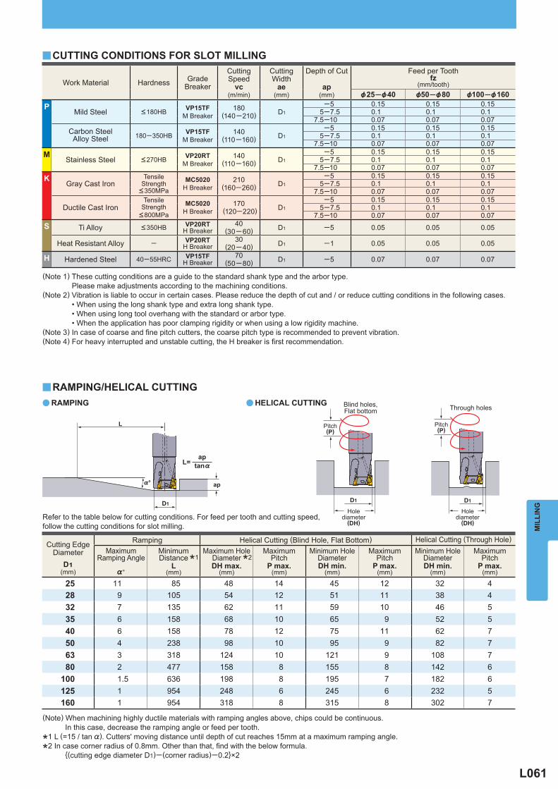
L061
Work Material Hardness GradeBreaker
CuttingSpeed
vc(m/min)
CuttingWidth
ae(mm)
Depth of Cut
ap(mm)
Feed per Tooth fz
(mm/tooth) &25─&40 &50─&80 &100─&160
P Mild Steel <180HB VP15TF
M Breaker 180
(140─210) D1
─5 0.15 0.15 0.155─7.5 0.1 0.1 0.1
7.5─10 0.07 0.07 0.07
Carbon SteelAlloy Steel 180─350HB VP15TF
M Breaker 140
(110─160) D1
─5 0.15 0.15 0.155─7.5 0.1 0.1 0.1
7.5─10 0.07 0.07 0.07M
Stainless Steel <270HB VP20RT M Breaker
140(110─160) D1
─5 0.15 0.15 0.155─7.5 0.1 0.1 0.1
7.5─10 0.07 0.07 0.07K
Gray Cast Iron Tensile
Strength <350MPa
MC5020 H Breaker
210(160─260) D1
─5 0.15 0.15 0.155─7.5 0.1 0.1 0.1
7.5─10 0.07 0.07 0.07
Ductile Cast Iron Tensile
Strength <800MPa
MC5020 H Breaker
170 (120─220) D1
─5 0.15 0.15 0.155─7.5 0.1 0.1 0.1
7.5─10 0.07 0.07 0.07S Ti Alloy <350HB VP20RT
H Breaker 40
(30─ 60) D1 ─5 0.05 0.05 0.05
Heat Resistant Alloy ─ VP20RT H Breaker
30(20─40) D1 ─1 0.05 0.05 0.05
H Hardened Steel 40─55HRC VP15TF H Breaker
70(50─80) D1 ─5 0.07 0.07 0.07
y
a a
y
Cutting EdgeDiameter
D1(mm)
Ramping Helical Cutting (Blind Hole, Flat Bottom) Helical Cutting (Through Hole)
Maximum
Ramping Angle
%°
MinimumDistance
L(mm)
Maximum Hole
DiameterDH max.
(mm)
MaximumPitch
P max.(mm)
Minimum Hole
DiameterDH min.
(mm)
MaximumPitch
P max.(mm)
Minimum Hole
DiameterDH min.
(mm)
MaximumPitch
P max.(mm)
25 11 85 48 14 45 12 32 428 9 105 54 12 51 11 38 432 7 135 62 11 59 10 46 535 6 158 68 10 65 9 52 540 6 158 78 12 75 11 62 750 4 238 98 10 95 9 82 763 3 318 124 10 121 9 108 780 2 477 158 8 155 8 142 6
100 1.5 636 198 8 195 7 182 6125 1 954 248 6 245 6 232 5160 1 954 318 8 315 8 302 7
*1
*2
%°
D1
ap
L
D1 D1
tan%
apL=
MIL
LIN
G
(Note 1) These cutting conditions are a guide to the standard shank type and the arbor type. Please make adjustments according to the machining conditions.(Note 2) Vibration is liable to occur in certain cases. Please reduce the depth of cut and / or reduce cutting conditions in the following cases. • When using the long shank type and extra long shank type. • When using long tool overhang with the standard or arbor type. • When the application has poor clamping rigidity or when using a low rigidity machine.(Note 3) In case of coarse and fi ne pitch cutters, the coarse pitch type is recommended to prevent vibration.(Note 4) For heavy interrupted and unstable cutting, the H breaker is fi rst recommendation.
RAMPING/HELICAL CUTTINGRAMPING HELICAL CUTTING
Pitch(P)
Pitch(P)
Holediameter
(DH)
Holediameter
(DH)
Through holesBlind holes,Flat bottom
Refer to the table below for cutting conditions. For feed per tooth and cutting speed, follow the cutting conditions for slot milling.
(Note) When machining highly ductile materials with ramping angles above, chips could be continuous. In this case, decrease the ramping angle or feed per tooth.
*1 L (=15 / tan %). Cutters' moving distance until depth of cut reaches 15mm at a maximum ramping angle.
*2 In case corner radius of 0.8mm. Other than that, fi nd with the below formula. {(cutting edge diameter D1)─ (corner radius)─0.2}×2
CUTTING CONDITIONS FOR SLOT MILLING
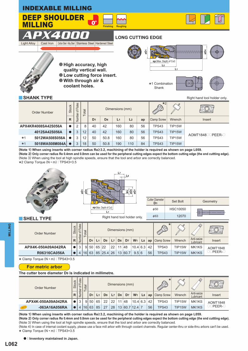
L062
Light Alloy Cast Iron Carbon Steel · Alloy Steel Stainless Steel Hardened Steel APX4000
Cutter Diameter D1 Set Bolt Geometry
&50 HSC10050
&63 12070
Order Number
Sto
ck
Numb
er of
Flutes
Tota
l
Dimensions (mm)* 2
R D1 D4 L1 L2 ap Clamp Screw Wrench Insert
APX4KR4008SA42S056A a 2 8 40 42 160 80 56 TPS43 TIP15W
AOMT1848ppPEER-p 4012SA42S056A a 3 12 40 42 160 80 56 TPS43 TIP15W
* 1 5012WA508S056A a 3 12 50 50.8 160 80 56 TPS43 TIP15W
* 1 5018WA508M084A a 3 18 50 50.8 190 110 84 TPS43 TIP15W
Order Number
Sto
ck
Numb
er of
Flutes
Tota
l
Dimensions (mm)*
R D1 L1 D9 L7 D8 D7 W1 L8 ap Clamp Screw Wrench Anti-seizeLubricant Insert
APX4K-050A09A042RA a 3 9 50 65 22 22 11 48 10.4 6.3 42 TPS43 TIP15W MK1KS AOMT1848ppPEER-pR06316CA056A a 4 16 63 85 25.4 26 13 60.7 9.5 6 56 TPS43 TIP15W MK1KS
y
y
Order Number
Sto
ck
Numb
er of
Flutes
Tota
l
Dimensions (mm)*
R D1 L1 D9 L7 D8 D7 W1 L8 ap Clamp Screw Wrench Anti-seizeLubricant Insert
APX4K-050A09A042RA a 3 9 50 65 22 22 11 48 10.4 6.3 42 TPS43 TIP15W MK1KS AOMT1848ppPEER-p -063A16A056RA a 4 16 63 85 27 28 13 60.7 12.4 7 56 TPS43 TIP15W MK1KS
L1
øD4
L2
øD1
ap
øD9
W1
øD8
L1
L7L8
øD1
ap
MIL
LIN
GINDEXABLE MILLING
(Note 1) When using inserts with corner radius Re>3.2, machining of the holder is required as shown on page L059.(Note 2) Only corner radius Re 0.4mm and 0.8mm can be used for the peripheral cutting edges expect the bottom cutting edge (the end cuttting edge).(Note 3) When using the tool at high spindle speeds, ensure that the tool and arbor are correctly balanced.(Note 4) In case of internal coolant supply, please use a face mill arbor with through coolant channels. Regular center-thru or side-thru arbors can't be used.
* Clamp Torque (N • m) : TPS43=3.5
(Note 1) When using inserts with corner radius Re>3.2, machining of the holder is required as shown on page L059.(Note 2) Only corner radius Re 0.4mm and 0.8mm can be used for the peripheral cutting edges expect the bottom cutting edge (the end cuttting edge).(Note 3) When using the tool at high spindle speeds, ensure that the tool and arbor are correctly balanced.
*2 Clamp Torque (N • m) : TPS43=3.5
SHANK TYPE Right hand tool holder only.
Right hand tool holder only.
Finishing Roughing
DEEP SHOULDER MILLING
(Max. Depth of Cut)
*1 Combination Shank
LONG CUTTING EDGE
High accuracy, high quality vertical wall.Low cutting force insert.With through air & coolant holes.
a
a
a
SHELL TYPE
(Max. Depth of Cut)
* Clamp Torque (N • m) : TPS43=3.5
a : Inventory maintained in Japan.
For metric arborThe cutter bore diameter D9 is indicated in millimetre.
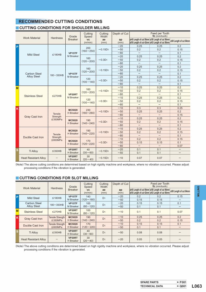
L063
Work Material Hardness GradeBreaker
CuttingSpeed
vc(m/min)
CuttingWidth
ae(mm)
Depth of Cut
ap(mm)
Feed per Tooth fz (mm/tooth)
&40 Length of cut 56mm&50 Length of cut 42mm
&50 Length of cut 56mm&63 Length of cut 56mm &50 Length of cut 84mm
P Mild Steel <180HB VP15TF M Breaker
140(120─160) D1
─20 0.2 0.2 0.15─50 0.15 0.15 ─
Carbon SteelAlloy Steel 180─350HB VP15TF
M Breaker 100
(80─120) D1─20 0.15 0.15 0.1─50 0.1 0.1 ─
M Stainless Steel <270HB VP20RT M Breaker
100 (80─120) D1 ─10 0.1 0.1 0.07
K Gray Cast Iron Tensile Strength <350MPa
MC5020 H Breaker
190(140─240) D1
─10 0.25 0.25 0.2─50 0.2 0.2 0.15
Ductile Cast Iron Tensile Strength <800MPa
MC5020 H Breaker
170 (120─220) D1
─10 0.15 0.15 0.1─50 0.1 0.1 ─
S Ti Alloy <350HB VP20RT H Breaker
40(30─60) D1 ─50 0.08 0.08 ─
Heat Resistant Alloy ─ VP20RT H Breaker
30(20─40) D1 ─20 0.05 0.05 ─
y
y
SPARE PARTS P001 TECHNICAL DATA Q001
Work Material Hardness GradeBreaker
CuttingSpeed
vc(m/min)
CuttingWidth
ae(mm)
Depth of Cut
ap(mm)
Feed per Tooth fz (mm/tooth)
&40 Length of cut 56mm&50 Length of cut 42mm
&50 Length of cut 56mm&63 Length of cut 56mm &50 Length of cut 84mm
P
Mild Steel <180HB VP15TF M Breaker
200(160─250) ─0.15D1
─20 0.25 0.25 0.2─50 0.2 0.2 0.15─80 ─ ─ 0.1
160(120─200) ─0.3D1
─20 0.25 0.25 0.2─50 0.2 0.2 0.15─80 ─ ─ 0.1
Carbon SteelAlloy Steel 180─350HB VP15TF
M Breaker
160(120─200) ─0.15D1
─20 0.25 0.25 0.2─50 0.2 0.2 0.15─80 ─ ─ 0.1
120(100─140) ─0.3D1
─20 0.25 0.25 0.2─50 0.2 0.2 0.15─80 ─ ─ 0.1
M
Stainless Steel <270HB VP20RT M Breaker
160(120─200) ─0.15D1
─10 0.25 0.25 0.2─50 0.2 0.2 0.15─80 ─ ─ 0.1
120(100─140) ─0.3D1
─10 0.25 0.25 0.2─50 0.2 0.2 0.15─80 ─ ─ 0.1
K
Gray Cast Iron Tensile
Strength <350MPa
MC5020 H Breaker
230(180─280) ─0.15D1
─10 0.3 0.3 0.25─50 0.25 0.25 0.2─80 ─ ─ 0.15
MC5020 H Breaker
190(140─240) ─0.3D1
─10 0.25 0.25 0.2─50 0.2 0.2 0.15─80 ─ ─ 0.1
Ductile Cast Iron Tensile
Strength <800MPa
MC5020 H Breaker
190(140─220) ─0.15D1
─10 0.25 0.25 0.2─50 0.2 0.2 0.15─80 ─ ─ 0.1
MC5020 H Breaker
170(120─220) ─0.3D1
─10 0.2 0.2 0.15─50 0.15 0.15 0.1─80 ─ ─ 0.07
S Ti Alloy <350HB VP20RT H Breaker
40(30─ 60) ─0.15D1
─20 0.1 0.1 ──50 0.1 0.1 ─
Heat Resistant Alloy ─ VP20RT H Breaker
30(20─40) ─0.15D1 ─10 0.07 0.07 ─
MIL
LIN
G
(Note) The above cutting conditons are determined based on high rigidity machine and workpiece, where no vibration occurred. Please adjust processing conditions if the vibration is generated.
(Note) The above cutting conditons are determined based on high rigidity machine and workpiece, where no vibration occurred. Please adjust processing conditions if the vibration is generated.
RECOMMENDED CUTTING CONDITIONSCUTTING CONDITIONS FOR SHOULDER MILLING
CUTTING CONDITIONS FOR SLOT MILLING
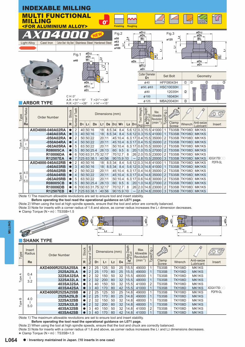
L064
Light Alloy Cast Iron Carbon Steel · Alloy Steel Stainless Steel Hardened Steel AXD4000
C H :0°A.R :+14°─15°R.R :+21°─+26°
T :+21°─+26°I :+14°─+15°
Cutter Diameter D1 Set Bolt Geometry
&40 HFF08043H z
&50, &63 HSC10030Hx&80 12035H
&100 16040H&125 MBA20040H c
z x c
Type
InsertRadius Order Number
Sto
ck
Numb
er of
Tee
th
Dimensions (mm)
Max
.Dep
thof
Cut
ap (mm)
Max.
AllowableRevolution
(min-1)
Type
(Fig
.)
Re R D1 L1 L2 D4 Clamp
Screw Wrench Anti-seizeLubricant Insert
Type
A
0.4
─
3.2
AXD4000R252SA25SA a 2 25 125 50 25 15.5 49000 1 TS3SB TKY08D MK1KS
XDGX1750pp
PDFR-GL
252SA25LA a 2 25 170 80 25 15.5 49000 1 TS3SB TKY08D MK1KS 322SA32SA a 2 32 150 50 32 15.5 48000 1 TS3SB TKY08D MK1KS 322SA32LA a 2 32 200 80 32 15.5 48000 1 TS3SB TKY08D MK1KS 403SA32SA a 3 40 150 50 32 15.5 41000 2 TS3SB TKY08D MK1KS 403SA42SA a 3 40 170 80 42 15.5 41000 1 TS3SB TKY08D MK1KS
Type
B
4.0
─
5.0
AXD4000R252SA25SB a 2 25 125 50 25 14.8 49000 1 TS3SB TKY08D MK1KS 252SA25LB a 2 25 170 80 25 14.8 49000 1 TS3SB TKY08D MK1KS 322SA32SB a 2 32 150 50 32 14.8 48000 1 TS3SB TKY08D MK1KS 322SA32LB a 2 32 200 80 32 14.8 48000 1 TS3SB TKY08D MK1KS 403SA32SB a 3 40 150 50 32 14.8 41000 2 TS3SB TKY08D MK1KS 403SA42SB a 3 40 170 80 42 14.8 41000 1 TS3SB TKY08D MK1KS
y
y
Type
Inser
t Rad
ius
Re
Order Number
Sto
ck
Numb
er of
Tee
th
Dimensions (mm)
Tool
Wei
ght
(kg)
Max
.Dep
thof
Cut
ap (mm)
Max.
AllowableRevolution(min-1)
Type
(Fig
.)
R D1 L1 D9 L7 D8 D12 W1 L8 D11 Clamp
Screw Wrench Anti-seizeLubricant Insert
Type
A
0.4
─
3.2
AXD4000-040A02RA a 2 40 50 16 18 8.5 34 8.4 5.6 12 0.3 15.5 41000 1 TS3SB TKY08D MK1KS
XDGX1750pp
PDFR-GL
-040A03RA a 3 40 50 16 18 8.5 34 8.4 5.6 12 0.3 15.5 41000 1 TS3SB TKY08D MK1KS -050A02RA a 2 50 50 22 20 11 45 10.4 6.3 17 0.4 15.5 35000 2 TS3SB TKY08D MK1KS -050A04RA a 4 50 50 22 20 11 45 10.4 6.3 17 0.4 15.5 35000 2 TS3SB TKY08D MK1KS -063A05RA a 5 63 50 22 20 11 50 10.4 6.3 17 0.6 15.5 30000 2 TS3SB TKY08D MK1KS R08005CA a 5 80 50 25.4 26 13 60 9.5 6 20 1.0 15.5 27000 2 TS3SB TKY08D MK1KS R10006DA a 6 100 63 31.75 32 17 70 12.7 8 26 2.0 15.5 23000 2 TS3SB TKY08D MK1KS R12507EA a 7 125 63 38.1 40 56 90 15.9 10 ─ 2.8 15.5 20000 3 TS3SB TKY08D MK1KS
Type
B
4.0
─
5.0
AXD4000-040A02RB a 2 40 50 16 18 8.5 34 8.4 5.6 12 0.3 14.8 41000 1 TS3SB TKY08D MK1KS -040A03RB a 3 40 50 16 18 8.5 34 8.4 5.6 12 0.3 14.8 41000 1 TS3SB TKY08D MK1KS -050A02RB a 2 50 50 22 20 11 45 10.4 6.3 17 0.4 14.8 35000 2 TS3SB TKY08D MK1KS -050A04RB a 4 50 50 22 20 11 45 10.4 6.3 17 0.4 14.8 35000 2 TS3SB TKY08D MK1KS -063A05RB a 5 63 50 22 20 11 50 10.4 6.3 17 0.6 14.8 30000 2 TS3SB TKY08D MK1KS R08005CB a 5 80 50 25.4 26 13 60 9.5 6 20 1.0 14.8 27000 2 TS3SB TKY08D MK1KS R10006DB a 6 100 63 31.75 32 17 70 12.7 8 26 2.0 14.8 23000 2 TS3SB TKY08D MK1KS R12507EB a 7 125 63 38.1 40 56 90 15.9 10 ─ 2.8 14.8 20000 3 TS3SB TKY08D MK1KS
*
*
øD1
øD4
apL2
L1
øD1
apL2
L1
øD4
L8L7
L1
ap
øD9øD12
W1
øD11
øD1
øD8
L8L7
L1
ap
øD9øD12
W1
øD8øD1
øD9øD12
øD8
øD1
L8L7
L1
ap
W1
øD11
ø125
ø40
ø50ø63ø80ø100
MIL
LIN
GINDEXABLE MILLING
Finishing Roughing
Including Flat faces
MULTI FUNCTIONAL MILLING<FOR ALUMINIUM ALLOY>
ARBOR TYPE
SHANK TYPE
(Note 1) The maximum allowable revolutions are set to ensure tool and insert stability. Before operating the tool read the operational guidance on L071 page.(Note 2) When using the tool at high spindle speeds, ensure that the tool and arbor are correctly balanced.(Note 3) Note for inserts with a corner radius of 1.6 and above, as corner radius increases the L1 dimension decreases.
* Clamp Torque (N • m) : TS3SB=1.5
(Note 1) The maximum allowable revolutions are set to ensure tool and insert stability. Before operating the tool read the operational guidance on L071 page.(Note 2) When using the tool at high spindle speeds, ensure that the tool and chuck are correctly balanced.(Note 3) Note for inserts with a corner radius of 1.6 and above, as corner radius increases the L1 and L2 dimensions decreases.
* Clamp Torque (N • m) : TS3SB=1.5
a : Inventory maintained in Japan. (10 inserts in one case)
Fig.1
Fig.2 Fig.3
L065
Work Material N Aluminium Alloy
Shape Order Number
Cla
ss
Hon
ing
Stock Dimensions (mm)
Geometry
Coated Carbide
L1 L4 S1 F1 Re
LC15
TF
TF15
XDGX175004PDFR-GL G F a a 23.0 17.5 5 1.7 0.4 175008PDFR-GL G F a a 23.0 17.5 5 1.3 0.8 175012PDFR-GL G F a a 23.0 17.5 5 0.9 1.2
175016PDFR-GL G F a a 22.0 17.5 5 1.4 1.6 175020PDFR-GL G F a a 22.0 17.5 5 1.0 2.0 175024PDFR-GL G F a a 22.0 17.5 5 0.6 2.4 175030PDFR-GL G F a a 21.1 17.5 5 0.8 3.0
175032PDFR-GL G F a a 21.1 17.5 5 0.6 3.2 175040PDFR-GL G F a a 20.0 17.5 5 0.8 4.0 175050PDFR-GL G F a a 19.4 17.5 5 0.4 5.0
Holder
A Holder B Holder
AXD4000–pppppppAAXD4000RppppppppA
AXD4000–pppppppBAXD4000RppppppppB
InsertCornerRadius
(Re) XDGX175004PDFR-GL
XDGX175008PDFR-GL
XDGX175012PDFR-GL
XDGX175016PDFR-GL
XDGX175020PDFR-GL
XDGX175024PDFR-GL
XDGX175030PDFR-GL
XDGX175032PDFR-GL
XDGX175040PDFR-GL
XDGX175050PDFR-GL
Work Material Grade
Cutting Speed vc
(m/min)
Cutting Width ae
(mm)
Depth of Cut ap
(mm)
Feed per Tooth (mm/tooth) Cutting Edge Diameter D1
&25 Cutting Edge Diameter D1
&32 Cutting Edge Diameter D1
&40 Cutting Edge Diameter D1
&50─&125
N
Aluminium Alloy LC15TFTF15
1000(200─3000) ─0.25 D1
─5 0.35 0.35 0.40 0.40 5─7.5 0.33 0.33 0.38 0.38
7.5─10 0.30 0.30 0.35 0.35 10─12.5 0.28 0.28 0.33 0.33
12.5─14.5 0.25 0.25 0.30 0.30
1000(200─3000) ─0.5 D1
─5 0.35 0.35 0.35 0.40 5─7.5 0.33 0.33 0.33 0.38
7.5─10 0.30 0.30 0.30 0.35 10─12.5 0.25 0.28 0.28 0.33
12.5─14.5 0.20 0.25 0.25 0.30
1000(200─3000) ─0.75 D1
─5 0.30 0.30 0.30 0.35 5─7.5 0.28 0.28 0.28 0.33
7.5─10 0.25 0.25 0.25 0.30 10─12.5 0.23 0.23 0.23 0.28
12.5─14.5 0.20 0.20 0.20 0.25
Work Material Grade
Cutting Speed vc
(m/min)
Cutting Width ae
(mm)
Depth of Cut ap
(mm)
Feed per Tooth (mm/tooth) Cutting Edge Diameter D1
&25 Cutting Edge Diameter D1
&32 Cutting Edge Diameter D1
&40 Cutting Edge Diameter D1
&50─&125
N
Aluminium Alloy LC15TFTF15
1000(200─3000) D1
─5 0.25 0.25 0.30 0.35 5─7.5 0.23 0.23 0.28 0.33
7.5─10 0.20 0.20 0.25 0.30 10─12.5 ─ 0.18 0.23 0.28
12.5─14.5 ─ 0.15 0.20 0.25
y
y
y
SPARE PARTS P001 TECHNICAL DATA Q001
S1
20°
F1
ReL1
30°L4
R0.8 R1.2 R1.6 R2.0 R2.4 R3.0R0.4 R3.2 R4.0 R5.0
MIL
LIN
G
INSERTSCutting Conditions (Guide) : : Stable Cutting : General Cutting : Unstable Cutting
Honing : F : Sharp
HOLDER AND INSERT CORNER RADIUS COMBINATION
RECOMMENDED CUTTING CONDITIONSCUTTING CONDITIONS FOR SHOULDER MILLING
CUTTING CONDITIONS FOR SLOT MILLING
(Note 1) The above cutting conditions are determined based on high workpiece and machine rigidity, where no vibration occurred. If vibrations occur make adjustments according to the machining conditions.(Note 2) Note, vibrations may occur in the following conditions. • When using long tool overhang. • When the workpiece has poor clamping rigidity or when the machine rigidity or workpiece rigidity is low,vibrations can occur easily, if so, reduce the cutting conditions. • When pocket machining corner radii.
(Note 1) The above cutting conditions are determined based on high workpiece and machine rigidity, where no vibration occurred. If vibrations occur make adjustments according to the machining conditions.(Note 2) Note, vibrations may occur in the following conditions. • When using long tool overhang. • When the workpiece has poor clamping rigidity or when the machine rigidity or workpiece rigidity is low,vibrations can occur easily, if so, reduce the cutting conditions. • When pocket machining corner radii.
L066
Type Insert
corner radiusRe
(mm)
Max. Drilling Depth (mm)
Cutting Edge Diameter D1 &25
Cutting Edge Diameter D1 &32
Cutting Edge Diameter D1 &40─&125
Type A 0.4─1.2 5.2 5.2 5.31.6─2.4 4.6 4.7 4.83.0─3.2 3.7 4.2 4.4
Type B 4.0 2.7 3.6 3.85.0 2.3 3.3 3.5
aa
y
y
Type Cutting Edge
DiameterD1
(mm)
Insertcorner radius
Re(mm)
Ramping Helical Cutting (Blind Hole, Flat Bottom) Helical Cutting (Through Hole) Maximum
Ramping Angle %°
Minimum Distance L
(mm)
Maximum Hole Diameter DH max.
(mm)
Maximum Pitch P max. (mm)
Minimum Hole Diameter DH min.
(mm)
Maximum Pitch P max. (mm)
Minimum Hole Diameter DH min.
(mm)
Maximum Pitch P max. (mm)
Type A
250.4─1.2 23.1 37 48.6 *2 29 45.7 27 31 71.6─2.4 22.0 39 46.2 *3 24 44.1 24 31 73.0─3.2 18.7 46 43.4 *4 19 42.6 18 32 6
320.4─1.2 15.4 57 62.6 *2 25 59.7 24 45 101.6─2.4 14.7 60 60.2 *3 21 58.0 21 45 103.0─3.2 13.8 64 57.4 *4 19 56.5 18 45 9
400.4─1.2 11.1 79 78.6 *2 22 75.7 22 61 121.6─2.4 10.4 85 76.2 *3 20 74.0 19 61 113.0─3.2 9.7 91 73.4 *4 17 72.4 17 61 11
500.4─1.2 8.2 108 98.6 *2 21 95.7 20 81 131.6─2.4 7.6 117 96.2 *3 18 93.9 18 81 123.0─3.2 6.9 129 93.4 *4 16 92.4 16 81 11
630.4─1.2 6.1 145 124.6 *2 20 121.6 19 107 141.6─2.4 5.6 159 122.2 *3 17 119.9 17 107 133.0─3.2 5.2 171 119.4 *4 16 118.3 15 107 12
800.4─1.2 4.6 193 158.6 *2 19 155.6 19 141 151.6─2.4 4.2 212 156.2 *3 17 153.9 17 141 133.0─3.2 3.8 234 153.4 *4 15 152.3 15 141 12
1000.4─1.2 3.5 254 198.6 *2 18 195.6 18 181 151.6─2.4 3.2 278 196.2 *3 16 193.9 16 181 143.0─3.2 2.9 306 193.4 *4 14 192.3 14 181 12
1250.4─1.2 2.7 329 248.6 *2 18 245.6 17 231 151.6─2.4 2.5 355 246.2 *3 16 243.9 16 231 143.0─3.2 2.3 386 243.4 *4 14 242.3 14 231 13
Type B
25 4.0 15.1 55 42.0 14 40.7 13 32 55.0 13.7 61 40.2 11 39.8 11 33 5
32 4.0 12.7 66 55.9 16 54.6 16 45 85.0 12.0 70 54.1 14 53.6 14 45 8
40 4.0 8.8 96 71.7 15 70.5 14 61 105.0 8.2 103 69.8 13 69.5 13 61 9
50 4.0 6.3 135 91.6 14 90.5 14 81 105.0 5.8 146 89.7 12 89.4 12 81 9
63 4.0 4.6 184 117.6 13 116.4 13 107 115.0 4.2 202 115.7 12 115.4 12 107 10
80 4.0 3.4 250 151.6 13 150.4 13 141 115.0 3.1 274 149.7 11 149.4 11 141 10
100 4.0 2.6 326 191.6 13 190.4 12 181 115.0 2.4 354 189.7 11 189.4 11 181 10
125 4.0 2.0 424 241.6 12 240.4 12 231 115.0 1.8 471 239.7 11 239.4 11 231 10
D1 D1 D1
L
%°
tan %
ap
apL=
MIL
LIN
GINDEXABLE MILLING
RAMPING/HELICAL CUTTINGRAMPING HELICAL
CUTTING Pitch(P)
Holediameter
(DH)
Holediameter
(DH)
Through holesBlind holes,Flat bottom
RAMPING/HELICAL CUTTING
*1
a : Inventory maintained in Japan.
Max. Drilling Depth
Note 1 The recommended ramping feed is 0.05mm/tooth or under.
*1 Using the maximum ramping angle, the distance to reach the maximum depth of cut is as follows:L= (maximum depth of cut ap/tan %). Maximum depth of cut A type is 15.5mm, B type is 14.8mm.
*2 Corner radius of 0.4mm. For other corner radii, use the following formula. {(cutting edge diameter D1)─ (corner radius Re)–0.3}×2
*3 Corner radius of 1.6mm. For other corner radii, use the following formula. {(cutting edge diameter D1)─ (corner radius Re)–0.3}×2
*4 Corner radius of 3.0mm. For other corner radii, use the following formula. {(cutting edge diameter D1)─ (corner radius Re)–0.3}×2
AXD4000 can be effectively used for pocket machining without the need for a prepared hole.
Pitch(P)
L067
Light Alloy Cast Iron Carbon Steel · Alloy Steel Stainless Steel Hardened Steel
Type
Inser
t Rad
ius
Order Number
Sto
ck
Numb
er of
Tee
th
Dimensions (mm)
Tool
Wei
ght
(kg)
Max
.Dep
thof
Cut
ap (mm)
Ramp
ing An
gle
%°
Max.
AllowableRevolution(min-1)
Type
(Fig
.)
*
R D1 L1 D9 L7 D8 D12 W1 L8 D11 ClampScrew Wrench Anti-seize
Lubricant Insert Re
Type
A
0.8
─
3.2
AXD7000-050A03RA a 3 50 50 22 20 11 45 10.4 6.3 17 0.4 21 9 30000 1 TS4SBL TKY15D MK1KS
XDGX2270pp
PDFR-GL
-063A03RA a 3 63 50 22 20 11 50 10.4 6.3 17 0.5 21 7 25000 1 TS4SBL TKY15D MK1KS
R08004CA a 4 80 63 25.4 26 13 63 9.5 6 20 1.2 21 5 23000 1 TS4SBL TKY15D MK1KS
R10005DA a 5 100 63 31.75 32 17 70 12.7 8 26 1.8 21 4 19000 1 TS4SBL TKY15D MK1KS
R12506EA a 6 125 63 38.1 40 56 90 15.9 10 ─ 2.7 21 3 16000 2 TS4SBL TKY15D MK1KS
Type
B
4.0
─
5.0
AXD7000-050A03RB a 3 50 50 22 20 11 45 10.4 6.3 17 0.4 20.4 8 30000 1 TS4SBL TKY15D MK1KS
-063A03RB a 3 63 50 22 20 11 50 10.4 6.3 17 0.5 20.4 6 25000 1 TS4SBL TKY15D MK1KS
R08004CB a 4 80 63 25.4 26 13 63 9.5 6 20 1.2 20.4 4 23000 1 TS4SBL TKY15D MK1KS
R10005DB a 5 100 63 31.75 32 17 70 12.7 8 26 1.8 20.4 3 19000 1 TS4SBL TKY15D MK1KS
R12506EB a 6 125 63 38.1 40 56 90 15.9 10 ─ 2.7 20.4 2 16000 2 TS4SBL TKY15D MK1KS
Cutter Diameter D1 Set Bolt Geometry
&50, &63 HSC10030Hz&80 12035H
&100 16040H&125 MBA20040H x
z x
Type
InsertRadius Order Number
Sto
ck
Numb
er of
Tee
th
Dimensions (mm)
M
ax.D
epth
of C
ut ap
(mm)
Ramp
ing An
gle
%°
Max.
AllowableRevolution
(min-1)
*
Re R D1 L1 L2 D4 ClampScrew Wrench Anti-seize
Lubricant Insert
Type
A
0.8
─
3.2
AXD7000R322SA32SA a 2 32 170 80 32 21 19 41000 TS4SB TKY15D MK1KS
XDGX2270pp
PDFR-GL402SA42SA a 2 40 170 80 42 21 13 36000 TS4SBL TKY15D MK1KS
Type
B
4.0
─
5.0
AXD7000R322SA32SB a 2 32 170 80 32 20.4 18 41000 TS4SB TKY15D MK1KS
402SA42SB a 2 40 170 80 42 20.4 11 36000 TS4SBL TKY15D MK1KS
AXD7000
y
y
C H :0°A.R :+11°R.R :+26°─+29°
T :+26°─+29°I :+11°
SPARE PARTS P001 TECHNICAL DATA Q001
L8L7
L1
ap
øD9øD12
W1
øD11
øD1
øD8
L8L7
L1
ap
øD9øD12
W1
øD8øD1
øD1
øD4
apL2
L1
ø50ø63ø80ø100
ø125
MIL
LIN
G
(Note 1) The maximum allowable revolutions are set to ensure tool and insert stability. Before operating the tool read the operational guidance on L071 page.(Note 2) When using the tool at high spindle speeds, ensure that the tool and arbor are correctly balanced.(Note 3) Note for inserts with a corner radius of 3.0 and above, as corner radius increases the L1 dimension decreases.
* Clamp Torque (N • m) : TS4SBL=3.5
(Note 1) The maximum allowable revolutions are set to ensure tool and insert stability. Before operating the tool read the operational guidance on L071 page.(Note 2) When using the tool at high spindle speeds, ensure that the tool and chuck are correctly balanced.(Note 3) Note for inserts with a corner radius of 3.0 and above, as corner radius increases the L1 and L2 dimensions decreases.
* Clamp Torque (N • m) : TS4SB=3.5, TS4SBL=3.5
ARBOR TYPE
SHANK TYPE Right hand tool holder only.
Right hand tool holder only.
Finishing Roughing
Including Flat faces
Fig.1 Fig.2
MULTI FUNCTIONAL MILLING<FOR ALUMINIUM ALLOY>
Low resistance chipbreaker.Low resistance insert and high rigidity design for excellent performance.For high-speed machining.Multi-functional machining.
a
a
a
a
L068
z x
Cutter Diameter D1 Set Bolt Geometry
&50, &63 HSC10030Hz&80 12035H
&100 16040H&125 MBA20040H x
Type
Inser
t Cor
ner
Re
Order Number
Sto
ck
Numb
er of
Tee
th
Dimensions (mm)
Tool
Wei
ght
(kg)
Max
.Dep
thof
Cut
ap (mm)
Ramp
ing An
gle
%°
Max.
AllowableRevolution(min-1)
Type
(Fig
.)
*
R D1 L1 D9 L7 D8 D12 W1 L8 D11 ClampScrew Wrench Anti-seize
Lubricant Insert
A ty
pe
0.8
─
3.2
AXD7000-050A03RA a 3 50 50 22 20 11 45 10.4 6.3 17 0.4 21 9 30000 1 TS4SBL TKY15D MK1KS
XDGX2270pp
PDFR-GL
-063A03RA a 3 63 50 22 20 11 45 10.4 6.3 17 0.5 21 7 25000 1 TS4SBL TKY15D MK1KS
-080A04RA a 4 80 63 27 23 13 63 12.4 7 20 1.2 21 5 23000 1 TS4SBL TKY15D MK1KS
-100A05RA a 5 100 63 32 26 17 70 14.4 8 26 1.8 21 4 19000 1 TS4SBL TKY15D MK1KS
-125B06RA a 6 125 63 40 40 56 90 16.4 9 ─ 2.7 21 3 16000 2 TS4SBL TKY15D MK1KS
B ty
pe
4.0
─
5.0
AXD7000-050A03RB a 3 50 50 22 20 11 45 10.4 6.3 17 0.4 20.4 8 30000 1 TS4SBL TKY15D MK1KS
-063A03RB a 3 63 50 22 20 11 45 10.4 6.3 17 0.5 20.4 6 25000 1 TS4SBL TKY15D MK1KS
-080A04RB a 4 80 63 27 23 13 63 12.4 7 20 1.2 20.4 4 23000 1 TS4SBL TKY15D MK1KS
-100A05RB a 5 100 63 32 26 17 70 14.4 8 26 1.8 20.4 3 19000 1 TS4SBL TKY15D MK1KS
-125B06RB a 6 125 63 40 40 56 90 16.4 9 ─ 2.7 20.4 2 16000 2 TS4SBL TKY15D MK1KS
Type
Inser
t Cor
ner
Re
Order Number
Sto
ck
Num
ber
of T
eeth
Dimensions (mm)
Max
.Dep
thof
Cut
ap (mm)
Ramp
ing An
gle
%°
Max.
AllowableRevolution(min-1)
*
R D1 L1 L2 ClampScrew Wrench Anti-seize
Lubricant Insert
A ty
pe
0.8
─
3.2
AXD7000R03202A-H63A a 2 32 127 80 21 19 41000 TS4SB TKY15D MK1KSXDGX2270pp
PDFR-GL04002A-H63A a 2 40 132 85 21 13 36000 TS4SBL TKY15D MK1KS
05003A-H63A a 3 50 137 90 21 9 30000 TS4SBL TKY15D MK1KS
y
y
C H :0°A.R :+11°R.R :+26°─+29°
T :+26°─+29°I :+11°
L8L7
L1
ap
øD9øD12
W1
øD11
øD1
øD8
L8L7
L1
ap
øD9øD12
W1
øD8øD1
ø63
L2L1
øD1
ap
HSK63A
ø50ø63ø80ø100
ø125
MIL
LIN
GINDEXABLE MILLING
(Note 1) The maximum allowable revolutions are set to ensure tool and insert stability. Before operating the tool read the operational guidance on L071 page.(Note 2) When using the tool at high spindle speeds, ensure that the tool and arbor are correctly balanced.(Note 3) Note for inserts with a corner radius of 3.0 and above, as corner radius increases the L1 dimension decreases.
* Clamp Torque (N • m) : TS4SBL=3.5
(Note 1) The maximum allowable revolutions are set to ensure tool and insert stability. Before operating the tool read the operational guidance on L071 page.(Note 2) When using the tool at high spindle speeds, ensure that the tool and chuck are correctly balanced.(Note 3) Note for inserts with a corner radius of 3.0 and above, as corner radius increases the L1 and L2 dimensions decreases.
* Clamp Torque (N • m) : TS4SB=3.5, TS4SBL=3.5
For metric arborThe cutter bore diameter D9 is indicated in millimetre.
ARBOR TYPE
HSK63A SHANK TYPE Right hand tool holder only.
Right hand tool holder only.
Fig.1 Fig.2
a : Inventory maintained in Japan. (10 inserts in one case)
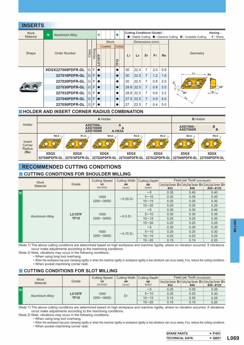
L069
Work Material N Aluminium Alloy
Shape Order Number
Cla
ss
Hon
ing
Stock Dimensions (mm)
Geometry
Coated Carbide
L1 L4 S1 F1 Re
LC15
TF
TF15
XDGX227008PDFR-GL G F a a 30 22.5 7 2.0 0.8227016PDFR-GL G F a a 30 22.5 7 1.2 1.6
227020PDFR-GL G F a a 30 22.5 7 0.8 2.0
227030PDFR-GL G F a a 28.8 22.5 7 0.8 3.0
227032PDFR-GL G F a a 28.8 22.5 7 0.6 3.2
227040PDFR-GL G F a a 27.5 22.5 7 0.9 4.0227050PDFR-GL G F a a 27 22.5 7 0.4 5.0
Holder
A Holder B Holder
AXD7000–pppppppAAXD7000RppppppppAAXD7000RppppA-H63A
AXD7000–pppppppBAXD7000RppppppppB
InsertCornerRadius
(Re) XDGX227008PDFR-GL
XDGX227016PDFR-GL
XDGX227020PDFR-GL
XDGX227030PDFR-GL
XDGX227032PDFR-GL
XDGX227040PDFR-GL
XDGX227050PDFR-GL
Work Material Grade
Cutting Speed vc
(m/min)
Cutting Width ae
(mm)
Cutting Depth ap
(mm)
Feed per Tooth (mm/tooth) Cutting Edge Diameter D1 Cutting Edge Diameter D1 Cutting Edge Diameter D1
&32 &40 &50–&125
N
Aluminium Alloy LC15TFTF15
1000(200─3000) ─0.25 D1
─5 0.35 0.40 0.40 5─10 0.30 0.35 0.3510─15 0.25 0.30 0.3015─20 0.20 0.25 0.25
1000(200─3000) ─0.5 D1
─5 0.35 0.35 0.40 5─10 0.30 0.30 0.3510─15 0.25 0.25 0.3015─20 0.20 0.20 0.25
1000(200─3000) ─0.75 D1
─5 0.30 0.30 0.35 5─10 0.25 0.25 0.3010─15 0.20 0.20 0.2515─20 0.15 0.15 0.20
Work Material Grade
Cutting Speed vc
(m/min)
Cutting Width ae
(mm)
Cutting Depth ap
(mm)
Feed per Tooth (mm/tooth) Cutting Edge Diameter D1 Cutting Edge Diameter D1 Cutting Edge Diameter D1
&32 &40 &50–&125
N Aluminium Alloy LC15TF
TF15 1000
(200─3000) D1
─5 0.25 0.30 0.35 5─10 0.20 0.25 0.3010─15 0.15 0.20 0.2515─20 0.10 0.15 0.20
y
y
y
SPARE PARTS P001 TECHNICAL DATA Q001
R0.8 R1.6 R2.0 R3.0 R3.2 R4.0 R5.0
S1
20°
F1
ReL1
30°L4
MIL
LIN
G
INSERTS
(Note 1) The above cutting conditions are determined based on high workpiece and machine rigidity, where no vibration occurred. If vibrations occur make adjustments according to the machining conditions.(Note 2) Note, vibrations may occur in the following conditions. • When using long tool overhang. • When the workpiece has poor clamping rigidity or when the machine rigidity or workpiece rigidity is low,vibrations can occur easily, if so, reduce the cutting conditions. • When pocket machining corner radii.
RECOMMENDED CUTTING CONDITIONSCUTTING CONDITIONS FOR SHOULDER MILLING
CUTTING CONDITIONS FOR SLOT MILLING
HOLDER AND INSERT CORNER RADIUS COMBINATION
(Note 1) The above cutting conditions are determined based on high workpiece and machine rigidity, where no vibration occurred. If vibrations occur make adjustments according to the machining conditions.(Note 2) Note, vibrations may occur in the following conditions. • When using long tool overhang. • When the workpiece has poor clamping rigidity or when the machine rigidity or workpiece rigidity is low,vibrations can occur easily, if so, reduce the cutting conditions. • When pocket machining corner radii.
Cutting Conditions (Guide) : : Stable Cutting : General Cutting : Unstable Cutting
Honing : F : Sharp
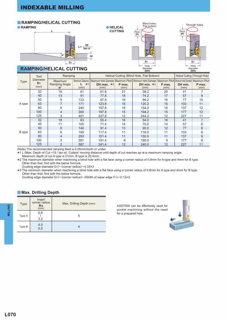
L070
a a
y
y
Type Insert
corner radiusRe
(mm) Max. Drilling Depth (mm)
Type A 0.8
─
3.25
Type B 4.05.0 4
Type
Tool Diameter
D1(mm)
Ramping Helical Cutting (Blind Hole, Flat Bottom) Helical Cutting (Through Hole)
MaximumRamping Angle
%°
Minimum Distance L
(mm)
Maximum Hole Diameter DH max.
(mm)
Maximum Pitch P max. (mm)
Minimum Hole Diameter DH min.
(mm)
Maximum Pitch P max. (mm)
Minimum Hole Diameter DH min.
(mm)
Maximum Pitch P max. (mm)
A type
32 19 61 61.8 21 58.2 20 41 740 13 91 77.8 18 74.2 17 57 950 9 133 97.8 16 94.2 16 77 1063 7 171 123.8 15 120.2 15 103 1180 5 240 157.8 16 154.2 15 137 12
100 4 300 197.8 15 194.2 15 177 12125 3 401 247.8 12 244.2 12 227 11
B type
32 18 63 55.4 16 54.0 16 41 740 11 105 71.4 14 70.0 14 57 850 8 146 91.4 13 90.0 12 77 863 6 195 117.4 11 116.0 11 103 880 4 293 151.4 11 150.0 11 137 9
100 3 391 191.4 9 190.0 9 177 8125 2 587 241.4 12 240.0 12 227 11
D1 D1 D1
L
%°
tan %
ap
apL=
MIL
LIN
GINDEXABLE MILLING
RAMPING/HELICAL CUTTING
(Note) The recommended ramping feed is 0.05mm/tooth or under.
*1 L (Max. Depth of Cut =15 / tan %). Cutters' moving distance until depth of cut reaches ap at a maximum ramping angle. Maximum depth of cut A type is 21mm, B type is 20.4mm.
*2 The maximum diameter when machining a blind hole with a fl at face using a corner radius of 0.8mm for A type and 4mm for B type. Other than that, fi nd with the below formula. {(cutting edge diameter D1)─ (corner radius)─0.3)}×2
*3 The minimum diameter when machining a blind hole with a fl at face using a corner radius of 0.8mm for A type and 4mm for B type. Other than that, fi nd with the below formula. {(cutting edge diameter D1)─ (corner radius)─ (Width of wiper edge F1)─0.1)}×2
RAMPING/HELICAL CUTTINGRAMPING HELICAL
CUTTING Pitch(P)
Pitch(P)
Holediameter
(DH)
Holediameter
(DH)
Through holesBlind holes,Flat bottom
*1 *2 *3
Max. Drilling Depth
AXD7000 can be effectively used for pocket machining without the need for a prepared hole.
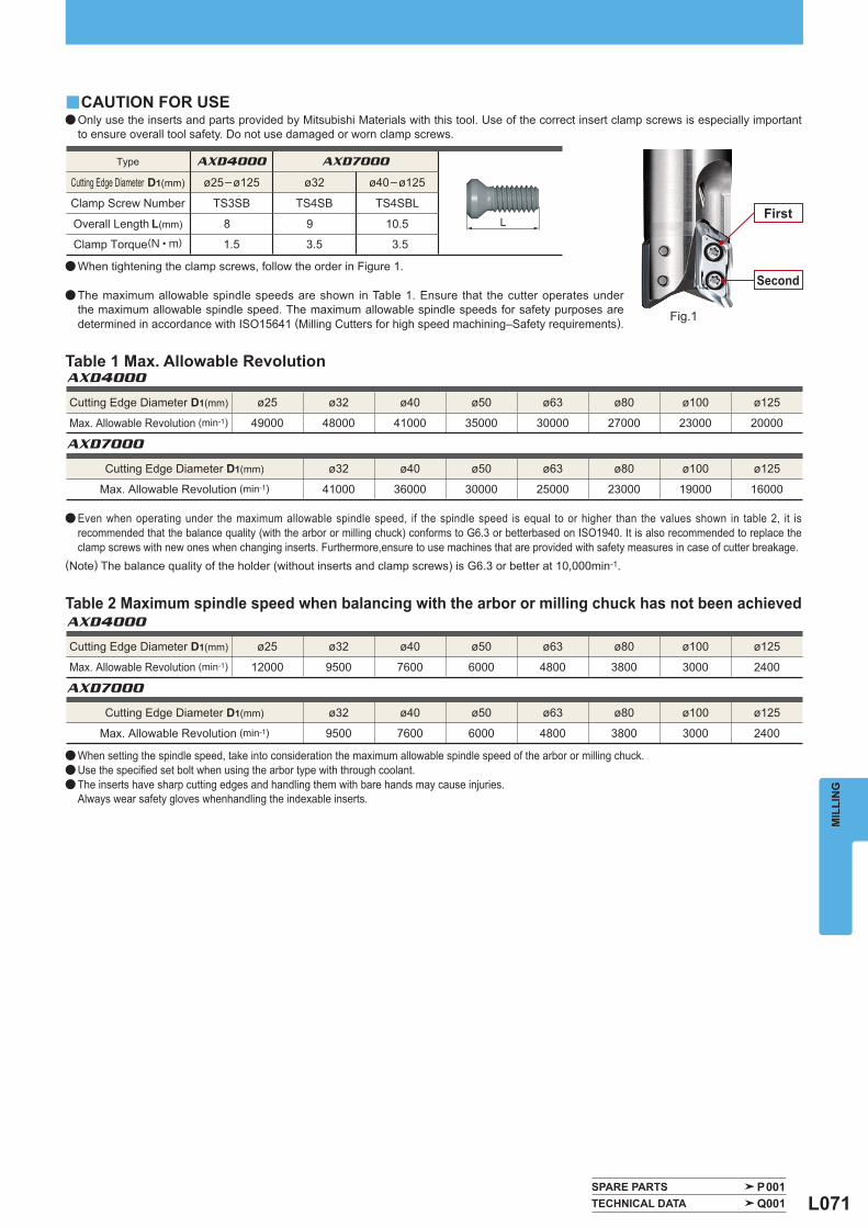
L071
AXD4000
AXD4000
AXD7000
AXD7000
Type AXD4000 AXD7000
Cutting Edge Diameter D1(mm) ø25–ø125 ø32 ø40–ø125
Clamp Screw Number TS3SB TS4SB TS4SBL
Overall Length L(mm) 8 9 10.5
Clamp Torque (N • m) 1.5 3.5 3.5
y
SPARE PARTS P001 TECHNICAL DATA Q001
Cutting Edge Diameter D1(mm) ø25 ø32 ø40 ø50 ø63 ø80 ø100 ø125
Max. Allowable Revolution (min-1) 49000 48000 41000 35000 30000 27000 23000 20000
Cutting Edge Diameter D1(mm) ø25 ø32 ø40 ø50 ø63 ø80 ø100 ø125
Max. Allowable Revolution (min-1) 12000 9500 7600 6000 4800 3800 3000 2400
Cutting Edge Diameter D1(mm) ø32 ø40 ø50 ø63 ø80 ø100 ø125
Max. Allowable Revolution (min-1) 41000 36000 30000 25000 23000 19000 16000
Cutting Edge Diameter D1(mm) ø32 ø40 ø50 ø63 ø80 ø100 ø125
Max. Allowable Revolution (min-1) 9500 7600 6000 4800 3800 3000 2400
L
MIL
LIN
G
Table 1 Max. Allowable Revolution
Table 2 Maximum spindle speed when balancing with the arbor or milling chuck has not been achieved
First
Second
Fig.1
CAUTION FOR USEa Only use the inserts and parts provided by Mitsubishi Materials with this tool. Use of the correct insert clamp screws is especially important
to ensure overall tool safety. Do not use damaged or worn clamp screws.
a When tightening the clamp screws, follow the order in Figure 1.
a The maximum allowable spindle speeds are shown in Table 1. Ensure that the cutter operates under the maximum allowable spindle speed. The maximum allowable spindle speeds for safety purposes are determined in accordance with ISO15641 (Milling Cutters for high speed machining–Safety requirements).
a Even when operating under the maximum allowable spindle speed, if the spindle speed is equal to or higher than the values shown in table 2, it is recommended that the balance quality (with the arbor or milling chuck) conforms to G6.3 or betterbased on ISO1940. It is also recommended to replace the clamp screws with new ones when changing inserts. Furthermore,ensure to use machines that are provided with safety measures in case of cutter breakage.
(Note) The balance quality of the holder (without inserts and clamp screws) is G6.3 or better at 10,000min-1.
a When setting the spindle speed, take into consideration the maximum allowable spindle speed of the arbor or milling chuck.a Use the specifi ed set bolt when using the arbor type with through coolant. a The inserts have sharp cutting edges and handling them with bare hands may cause injuries. Always wear safety gloves whenhandling the indexable inserts.
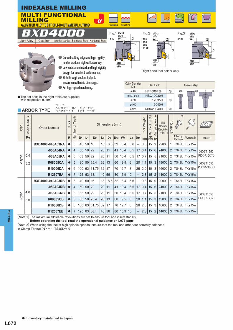
L072
Light Alloy Cast Iron Carbon Steel · Alloy Steel Stainless Steel Hardened Steel
Cutter Diameter D1 Set Bolt Geometry
&40 HFF08043H z
&50, &63 HSC10030Hx&80 12035H
&100 16040H&125 MBA20040H c
z x c
BXD4000
y
C H :0°A.R :+11°─+15°R.R :+8°─+16°
T :+8°─+16°I :+11°─+15°
Type
Inse
rt R
adiu
s
Re
Order Number
Sto
ck
Num
ber o
f Tee
th
Dimensions (mm)
Tool
Wei
ght
(kg)
Max
.Dep
th o
f Cut
ap (mm)
Ram
ping
Ang
le
%°
Max.
AllowableRevolution(min-1)
Type
(Fig
.)
*
R D1 L1 D9 L7 D8 D12 W1 L8 D11 ClampScrew Wrench Insert
A ty
pe
0.4
─
3.2
BXD4000 -040A03RA a 3 40 50 16 18 8.5 32 8.4 5.6 ─ 0.3 15 9 29000 1 TS4SL TKY15W
XDGT1550PDoR-Goo
XDGT1550PDoR-GLoo
-050A04RA a 4 50 50 22 20 11 41 10.4 6.5 17 0.4 15 6 24000 2 TS4SL TKY15W
-063A05RA a 5 63 50 22 20 11 50 10.4 6.5 17 0.7 15 5 21000 2 TS4SL TKY15W
R08005CA a 5 80 50 25.4 26 13 60 9.5 6 20 1.1 15 3 19000 2 TS4SL TKY15W
R10006DA a 6 100 63 31.75 32 17 70 12.7 8 26 2.0 15 3 16000 2 TS4SL TKY15W
R12507EA a 7 125 63 38.1 40 56 80 15.9 10 ─ 2.8 15 2 14000 3 TS4SL TKY15W
B ty
pe
4.0
─
5.0
BXD4000 -040A03RB a 3 40 50 16 18 8.5 32 8.4 5.6 ─ 0.3 15 9 29000 1 TS4SL TKY15W
XDGT1550PDoR-Goo
-050A04RB a 4 50 50 22 20 11 41 10.4 6.5 17 0.4 15 6 24000 2 TS4SL TKY15W
-063A05RB a 5 63 50 22 20 11 50 10.4 6.5 17 0.7 15 5 21000 2 TS4SL TKY15W
R08005CB a 5 80 50 25.4 26 13 60 9.5 6 20 1.1 15 3 19000 2 TS4SL TKY15W
R10006DB a 6 100 63 31.75 32 17 70 12.7 8 26 2.0 15 3 16000 2 TS4SL TKY15W
R12507EB a 7 125 63 38.1 40 56 80 15.9 10 ─ 2.8 15 2 14000 3 TS4SL TKY15W
øD8øD11øD1
L8L7
L1
ap
øD9øD12
W1 L8L7
L1ap
øD8øD1
øD9øD12
W1øD9øD12
øD8
øD1
L8L7
L1
ap
W1ø40 ø50ø63ø80ø100
ø125
MIL
LIN
GINDEXABLE MILLING
aThe set bolts in the right table are supplied with respective cutter.
ARBOR TYPE
Right hand tool holder only.
Finishing Roughing
Including Flat faces
Fig.1 Fig.2 Fig.3
MULTI FUNCTIONAL MILLING<ALUMINIUM ALLOY TO DIFFICULT-TO-CUT MATERIAL CUTTING>
Curved cutting edge and high rigidity holder produce high wall accuracy.Low resistance insert and high rigidity design for excellent performance.With through coolant holes to ensure smooth chip discharge.For high-speed machining.
a
a
a
a
a : Inventory maintained in Japan.
(Note 1) The maximum allowable revolutions are set to ensure tool and insert stability. Before operating the tool read the operational guidance on L073 page.(Note 2) When using the tool at high spindle speeds, ensure that the tool and arbor are correctly balanced.
* Clamp Torque (N • m) : TS4SL=4.0
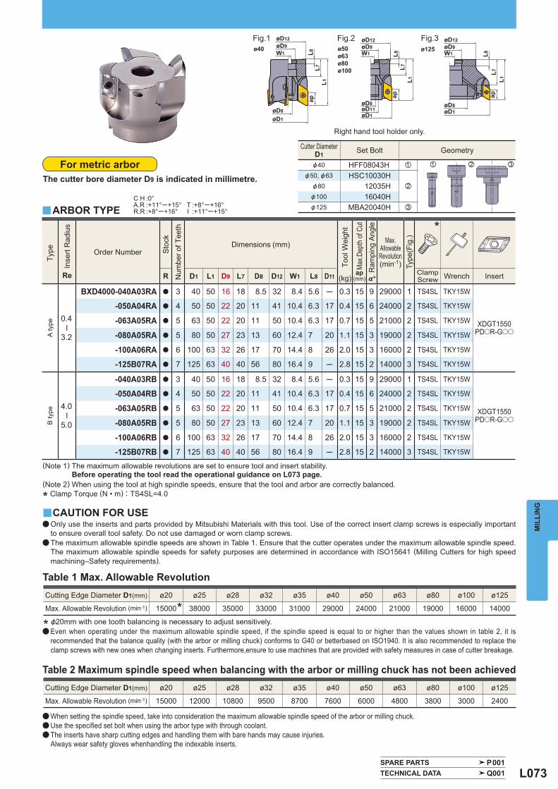
L073
Type
Inse
rt R
adiu
s
Re
Order Number
Sto
ck
Num
ber o
f Tee
th
Dimensions (mm)
Tool
Wei
ght
(kg)
Max
.Dep
th o
f Cut
ap (mm)
Ram
ping
Ang
le
%°
Max.
AllowableRevolution(min-1)
Type
(Fig
.)
*
R D1 L1 D9 L7 D8 D12 W1 L8 D11 ClampScrew Wrench Insert
A ty
pe
0.4
─
3.2
BXD4000-040A03RA a 3 40 50 16 18 8.5 32 8.4 5.6 ─ 0.3 15 9 29000 1 TS4SL TKY15W
XDGT1550PDoR-Goo
-050A04RA a 4 50 50 22 20 11 41 10.4 6.3 17 0.4 15 6 24000 2 TS4SL TKY15W
-063A05RA a 5 63 50 22 20 11 50 10.4 6.3 17 0.7 15 5 21000 2 TS4SL TKY15W
-080A05RA a 5 80 50 27 23 13 60 12.4 7 20 1.1 15 3 19000 2 TS4SL TKY15W
-100A06RA a 6 100 63 32 26 17 70 14.4 8 26 2.0 15 3 16000 2 TS4SL TKY15W
-125B07RA a 7 125 63 40 40 56 80 16.4 9 ─ 2.8 15 2 14000 3 TS4SL TKY15W
B ty
pe
4.0
─
5.0
-040A03RB a 3 40 50 16 18 8.5 32 8.4 5.6 ─ 0.3 15 9 29000 1 TS4SL TKY15W
XDGT1550PDoR-Goo
-050A04RB a 4 50 50 22 20 11 41 10.4 6.3 17 0.4 15 6 24000 2 TS4SL TKY15W
-063A05RB a 5 63 50 22 20 11 50 10.4 6.3 17 0.7 15 5 21000 2 TS4SL TKY15W
-080A05RB a 5 80 50 27 23 13 60 12.4 7 20 1.1 15 3 19000 2 TS4SL TKY15W
-100A06RB a 6 100 63 32 26 17 70 14.4 8 26 2.0 15 3 16000 2 TS4SL TKY15W
-125B07RB a 7 125 63 40 40 56 80 16.4 9 ─ 2.8 15 2 14000 3 TS4SL TKY15W
Cutter Diameter D1 Set Bolt Geometry
&40 HFF08043H z
&50, &63 HSC10030Hx&80 12035H
&100 16040H&125 MBA20040H c
z x c
y
C H :0°A.R :+11°─+15°R.R :+8°─+16°
T :+8°─+16°I :+11°─+15°
SPARE PARTS P001 TECHNICAL DATA Q001
y
Cutting Edge Diameter D1(mm) ø20 ø25 ø28 ø32 ø35 ø40 ø50 ø63 ø80 ø100 ø125
Max. Allowable Revolution (min-1) 15000 38000 35000 33000 31000 29000 24000 21000 19000 16000 14000*
Cutting Edge Diameter D1(mm) ø20 ø25 ø28 ø32 ø35 ø40 ø50 ø63 ø80 ø100 ø125
Max. Allowable Revolution (min-1) 15000 12000 10800 9500 8700 7600 6000 4800 3800 3000 2400
øD8øD11øD1
L8L7
L1
ap
øD9øD12
W1 L8L7
L1ap
øD8øD1
øD9øD12
W1øD9øD12
øD8
øD1
L8L7
L1
ap
W1ø40 ø50
ø63ø80ø100
ø125
MIL
LIN
G
For metric arborThe cutter bore diameter D9 is indicated in millimetre.
ARBOR TYPE
Right hand tool holder only.
Fig.1 Fig.2 Fig.3
(Note 1) The maximum allowable revolutions are set to ensure tool and insert stability. Before operating the tool read the operational guidance on L073 page.(Note 2) When using the tool at high spindle speeds, ensure that the tool and arbor are correctly balanced.
* Clamp Torque (N • m) : TS4SL=4.0
CAUTION FOR USEa Only use the inserts and parts provided by Mitsubishi Materials with this tool. Use of the correct insert clamp screws is especially important
to ensure overall tool safety. Do not use damaged or worn clamp screws.a The maximum allowable spindle speeds are shown in Table 1. Ensure that the cutter operates under the maximum allowable spindle speed.
The maximum allowable spindle speeds for safety purposes are determined in accordance with ISO15641 (Milling Cutters for high speed machining–Safety requirements).
Table 1 Max. Allowable Revolution
a Even when operating under the maximum allowable spindle speed, if the spindle speed is equal to or higher than the values shown in table 2, it is recommended that the balance quality (with the arbor or milling chuck) conforms to G40 or betterbased on ISO1940. It is also recommended to replace the clamp screws with new ones when changing inserts. Furthermore,ensure to use machines that are provided with safety measures in case of cutter breakage.
Table 2 Maximum spindle speed when balancing with the arbor or milling chuck has not been achieved
a When setting the spindle speed, take into consideration the maximum allowable spindle speed of the arbor or milling chuck.a Use the specifi ed set bolt when using the arbor type with through coolant. a The inserts have sharp cutting edges and handling them with bare hands may cause injuries. Always wear safety gloves whenhandling the indexable inserts.
* &20mm with one tooth balancing is necessary to adjust sensitively.
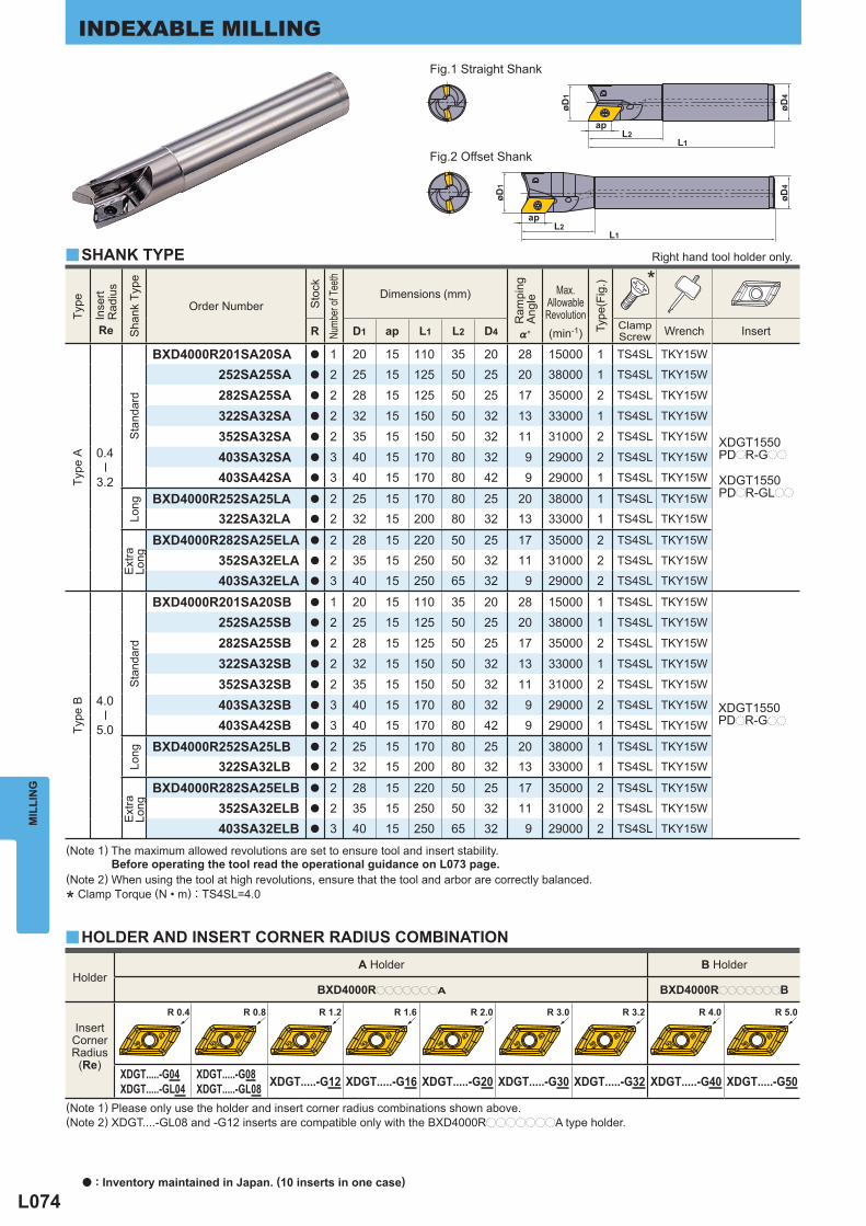
L074
Holder A Holder B Holder
BXD4000RpppppppA BXD4000RpppppppB
InsertCornerRadius
(Re) XDGT.....-G04XDGT.....-GL04
XDGT.....-G08XDGT.....-GL08 XDGT.....-G12 XDGT.....-G16 XDGT.....-G20 XDGT.....-G30 XDGT.....-G32 XDGT.....-G40 XDGT.....-G50
Type
Inse
rt R
adiu
s
Re
Sha
nk T
ype
Order Number
Sto
ck
Numb
er of
Tee
th
Dimensions (mm)
Ram
ping
Ang
le
%°
Max.
AllowableRevolution(min-1)
Type
(Fig
.)
*
R D1 ap L1 L2 D4 ClampScrew Wrench Insert
Type
A
0.4
─
3.2
Sta
ndar
d
BXD4000R201SA20SA a 1 20 15 110 35 20 28 15000 1 TS4SL TKY15W
XDGT1550PDpR-Gpp
XDGT1550PDpR-GLpp
252SA25SA a 2 25 15 125 50 25 20 38000 1 TS4SL TKY15W
282SA25SA a 2 28 15 125 50 25 17 35000 2 TS4SL TKY15W
322SA32SA a 2 32 15 150 50 32 13 33000 1 TS4SL TKY15W
352SA32SA a 2 35 15 150 50 32 11 31000 2 TS4SL TKY15W
403SA32SA a 3 40 15 170 80 32 9 29000 2 TS4SL TKY15W
403SA42SA a 3 40 15 170 80 42 9 29000 1 TS4SL TKY15W
Long
BXD4000R252SA25LA a 2 25 15 170 80 25 20 38000 1 TS4SL TKY15W
322SA32LA a 2 32 15 200 80 32 13 33000 1 TS4SL TKY15W
Ext
raLo
ng
BXD4000R282SA25ELA a 2 28 15 220 50 25 17 35000 2 TS4SL TKY15W
352SA32ELA a 2 35 15 250 50 32 11 31000 2 TS4SL TKY15W
403SA32ELA a 3 40 15 250 65 32 9 29000 2 TS4SL TKY15W
Type
B
4.0
─
5.0
Sta
ndar
d
BXD4000R201SA20SB a 1 20 15 110 35 20 28 15000 1 TS4SL TKY15W
252SA25SB a 2 25 15 125 50 25 20 38000 1 TS4SL TKY15W
282SA25SB a 2 28 15 125 50 25 17 35000 2 TS4SL TKY15W
322SA32SB a 2 32 15 150 50 32 13 33000 1 TS4SL TKY15W
352SA32SB a 2 35 15 150 50 32 11 31000 2 TS4SL TKY15W
403SA32SB a 3 40 15 170 80 32 9 29000 2 TS4SL TKY15W
403SA42SB a 3 40 15 170 80 42 9 29000 1 TS4SL TKY15W
Long
BXD4000R252SA25LB a 2 25 15 170 80 25 20 38000 1 TS4SL TKY15W
322SA32LB a 2 32 15 200 80 32 13 33000 1 TS4SL TKY15W
Ext
raLo
ng
BXD4000R282SA25ELB a 2 28 15 220 50 25 17 35000 2 TS4SL TKY15W
352SA32ELB a 2 35 15 250 50 32 11 31000 2 TS4SL TKY15W
403SA32ELB a 3 40 15 250 65 32 9 29000 2 TS4SL TKY15W
XDGT1550PDpR-Gpp
y
y
øD1
øD4
apL2
L1
øD1
øD4
apL2
L1
R 0.4 R 0.8 R 1.6R 1.2 R 2.0 R 3.0 R 3.2 R 4.0 R 5.0
MIL
LIN
GINDEXABLE MILLING
(Note 1) Please only use the holder and insert corner radius combinations shown above.(Note 2) XDGT....-GL08 and -G12 inserts are compatible only with the BXD4000RpppppppA type holder.
(Note 1) The maximum allowed revolutions are set to ensure tool and insert stability. Before operating the tool read the operational guidance on L073 page.(Note 2) When using the tool at high revolutions, ensure that the tool and arbor are correctly balanced.
* Clamp Torque (N • m) : TS4SL=4.0
SHANK TYPE Right hand tool holder only.
Fig.1 Straight Shank
Fig.2 Offset Shank
HOLDER AND INSERT CORNER RADIUS COMBINATION
a : Inventory maintained in Japan. (10 inserts in one case)
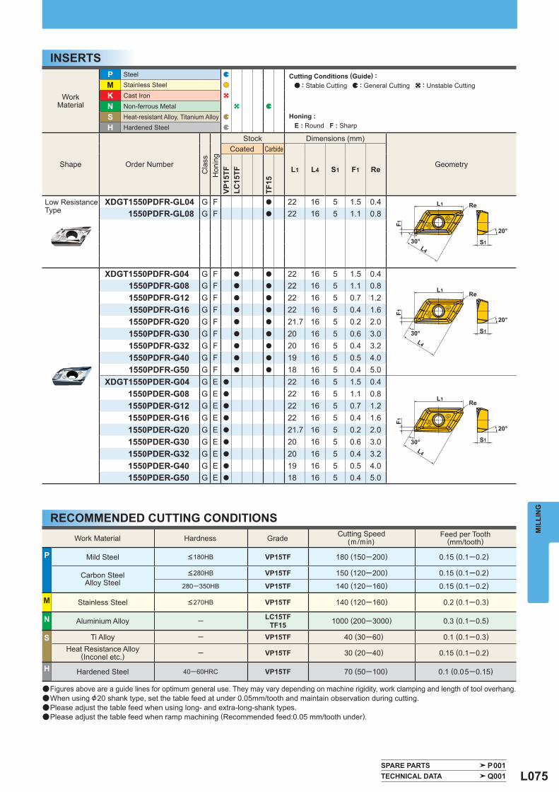
L075
Work Material Hardness Grade Cutting Speed (m/min)
Feed per Tooth (mm/tooth)
P Mild Steel <180HB VP15TF 180 (150─200) 0.15 (0.1─0.2)
Carbon SteelAlloy Steel
<280HB VP15TF 150 (120─200) 0.15 (0.1─0.2)
280─350HB VP15TF 140 (120─160) 0.15 (0.1─0.2)
M Stainless Steel <270HB VP15TF 140 (120─160) 0.2 (0.1─0.3)
N Aluminium Alloy ─ LC15TFTF15 1000 (200─3000) 0.3 (0.1─0.5)
S Ti Alloy ─ VP15TF 40 (30─60) 0.1 (0.1─0.3)
Heat Resistance Alloy(Inconel etc.) ─ VP15TF 30 (20─40) 0.15 (0.1─0.2)
H Hardened Steel 40─60HRC VP15TF 70 (50─100) 0.1 (0.05─0.15)
Work Material
P Steel
M Stainless Steel
K Cast Iron
N Non-ferrous Metal
S Heat-resistant Alloy, Titanium Alloy
H Hardened Steel
Shape Order Number
Cla
ss
Hon
ing
Stock Dimensions (mm)
Geometry
Coated Carbide
L1 L4 S1 F1 Re
VP15
TFLC
15TF
TF15
Low Resistance Type
XDGT1550PDFR-GL04 G F a 22 16 5 1.5 0.41550PDFR-GL08 G F a 22 16 5 1.1 0.8
XDGT1550PDFR-G04 G F a a 22 16 5 1.5 0.41550PDFR-G08 G F a a 22 16 5 1.1 0.81550PDFR-G12 G F a a 22 16 5 0.7 1.21550PDFR-G16 G F a a 22 16 5 0.4 1.61550PDFR-G20 G F a a 21.7 16 5 0.2 2.01550PDFR-G30 G F a a 20 16 5 0.6 3.01550PDFR-G32 G F a a 20 16 5 0.4 3.21550PDFR-G40 G F a a 19 16 5 0.5 4.01550PDFR-G50 G F a a 18 16 5 0.4 5.0
XDGT1550PDER-G04 G E a 22 16 5 1.5 0.41550PDER-G08 G E a 22 16 5 1.1 0.81550PDER-G12 G E a 22 16 5 0.7 1.21550PDER-G16 G E a 22 16 5 0.4 1.61550PDER-G20 G E a 21.7 16 5 0.2 2.01550PDER-G30 G E a 20 16 5 0.6 3.01550PDER-G32 G E a 20 16 5 0.4 3.21550PDER-G40 G E a 19 16 5 0.5 4.01550PDER-G50 G E a 18 16 5 0.4 5.0
SPARE PARTS P001 TECHNICAL DATA Q001
S1
L4
F1
ReL1
30°
20°
S1
L4
F1Re
L1
30°
20°
S1L4
F1
ReL1
30°20°
MIL
LIN
G
INSERTS
RECOMMENDED CUTTING CONDITIONS
Cutting Conditions (Guide) : : Stable Cutting : General Cutting : Unstable Cutting
Honing : E : Round F : Sharp
a Figures above are a guide lines for optimum general use. They may vary depending on machine rigidity, work clamping and length of tool overhang.a When using &20 shank type, set the table feed at under 0.05mm/tooth and maintain observation during cutting.a Please adjust the table feed when using long- and extra-long-shank types.a Please adjust the table feed when ramp machining (Recommended feed:0.05 mm/tooth under).
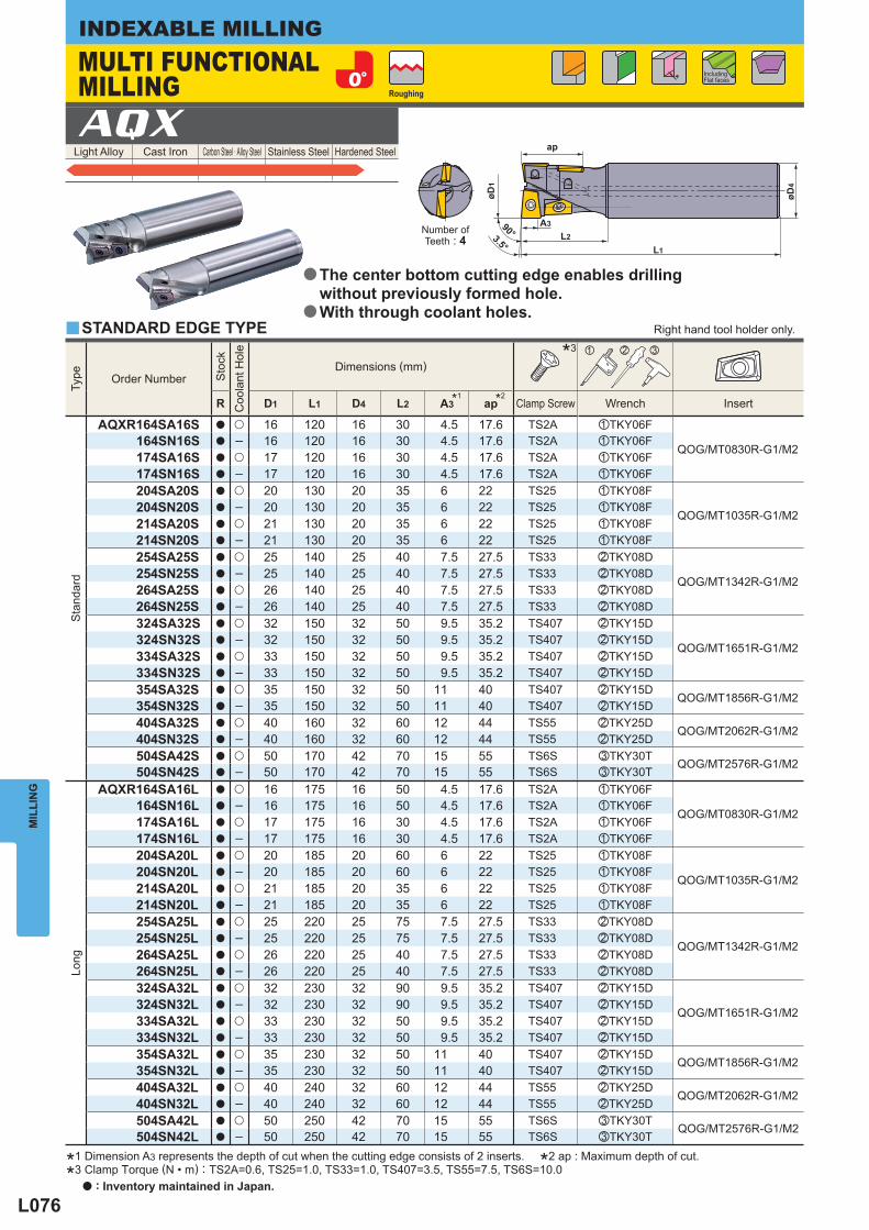
L076
Light Alloy Cast Iron Carbon Steel · Alloy Steel Stainless Steel Hardened Steel AQX
y
Type
Order Number
Sto
ck
Coo
lant
Hol
e
Dimensions (mm) * 3 z x c
R D1 L1 D4 L2 * 1A3 * 2ap Clamp Screw Wrench Insert
Sta
ndar
d
AQXR164SA16S a u 16 120 16 30 4.5 17.6 TS2A zTKY06F
QOG/MT0830R-G1/M2164SN16S a ─ 16 120 16 30 4.5 17.6 TS2A zTKY06F174SA16S a u 17 120 16 30 4.5 17.6 TS2A zTKY06F174SN16S a ─ 17 120 16 30 4.5 17.6 TS2A zTKY06F204SA20S a u 20 130 20 35 6 22 TS25 zTKY08F
QOG/MT1035R-G1/M2204SN20S a ─ 20 130 20 35 6 22 TS25 zTKY08F214SA20S a u 21 130 20 35 6 22 TS25 zTKY08F214SN20S a ─ 21 130 20 35 6 22 TS25 zTKY08F254SA25S a u 25 140 25 40 7.5 27.5 TS33 xTKY08D
QOG/MT1342R-G1/M2254SN25S a ─ 25 140 25 40 7.5 27.5 TS33 xTKY08D264SA25S a u 26 140 25 40 7.5 27.5 TS33 xTKY08D264SN25S a ─ 26 140 25 40 7.5 27.5 TS33 xTKY08D324SA32S a u 32 150 32 50 9.5 35.2 TS407 xTKY15D
QOG/MT1651R-G1/M2324SN32S a ─ 32 150 32 50 9.5 35.2 TS407 xTKY15D334SA32S a u 33 150 32 50 9.5 35.2 TS407 xTKY15D334SN32S a ─ 33 150 32 50 9.5 35.2 TS407 xTKY15D354SA32S a u 35 150 32 50 11 40 TS407 xTKY15D
QOG/MT1856R-G1/M2354SN32S a ─ 35 150 32 50 11 40 TS407 xTKY15D404SA32S a u 40 160 32 60 12 44 TS55 xTKY25D
QOG/MT2062R-G1/M2404SN32S a ─ 40 160 32 60 12 44 TS55 xTKY25D504SA42S a u 50 170 42 70 15 55 TS6S cTKY30T
QOG/MT2576R-G1/M2504SN42S a ─ 50 170 42 70 15 55 TS6S cTKY30T
Long
AQXR164SA16L a u 16 175 16 50 4.5 17.6 TS2A zTKY06F
QOG/MT0830R-G1/M2164SN16L a ─ 16 175 16 50 4.5 17.6 TS2A zTKY06F174SA16L a u 17 175 16 30 4.5 17.6 TS2A zTKY06F174SN16L a ─ 17 175 16 30 4.5 17.6 TS2A zTKY06F204SA20L a u 20 185 20 60 6 22 TS25 zTKY08F
QOG/MT1035R-G1/M2204SN20L a ─ 20 185 20 60 6 22 TS25 zTKY08F214SA20L a u 21 185 20 35 6 22 TS25 zTKY08F214SN20L a ─ 21 185 20 35 6 22 TS25 zTKY08F254SA25L a u 25 220 25 75 7.5 27.5 TS33 xTKY08D
QOG/MT1342R-G1/M2254SN25L a ─ 25 220 25 75 7.5 27.5 TS33 xTKY08D264SA25L a u 26 220 25 40 7.5 27.5 TS33 xTKY08D264SN25L a ─ 26 220 25 40 7.5 27.5 TS33 xTKY08D324SA32L a u 32 230 32 90 9.5 35.2 TS407 xTKY15D
QOG/MT1651R-G1/M2324SN32L a ─ 32 230 32 90 9.5 35.2 TS407 xTKY15D334SA32L a u 33 230 32 50 9.5 35.2 TS407 xTKY15D334SN32L a ─ 33 230 32 50 9.5 35.2 TS407 xTKY15D354SA32L a u 35 230 32 50 11 40 TS407 xTKY15D
QOG/MT1856R-G1/M2354SN32L a ─ 35 230 32 50 11 40 TS407 xTKY15D404SA32L a u 40 240 32 60 12 44 TS55 xTKY25D
QOG/MT2062R-G1/M2404SN32L a ─ 40 240 32 60 12 44 TS55 xTKY25D504SA42L a u 50 250 42 70 15 55 TS6S cTKY30T
QOG/MT2576R-G1/M2504SN42L a ─ 50 250 42 70 15 55 TS6S cTKY30T
90°3.5° L1
øD4
øD1
L2
A3
ap
MIL
LIN
GINDEXABLE MILLING
*1 Dimension A3 represents the depth of cut when the cutting edge consists of 2 inserts. *2 ap : Maximum depth of cut.
*3 Clamp Torque (N • m) : TS2A=0.6, TS25=1.0, TS33=1.0, TS407=3.5, TS55=7.5, TS6S=10.0
Number ofTeeth : 4
Right hand tool holder only.
MULTI FUNCTIONAL MILLING Roughing
Including Flat faces
STANDARD EDGE TYPE
The center bottom cutting edge enables drilling without previously formed hole.With through coolant holes.
a
a
a : Inventory maintained in Japan.
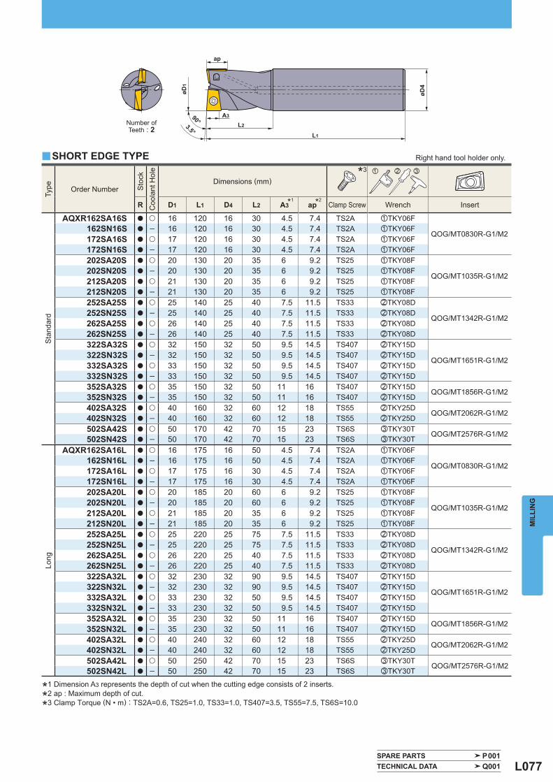
L077
Type
Order Number
Sto
ck
Coo
lant
Hol
e
Dimensions (mm) * 3 z x c
R D1 L1 D4 L2 * 1A3 * 2ap Clamp Screw Wrench Insert
Sta
ndar
d
AQXR162SA16S a u 16 120 16 30 4.5 7.4 TS2A zTKY06F
QOG/MT0830R-G1/M2162SN16S a ─ 16 120 16 30 4.5 7.4 TS2A zTKY06F172SA16S a u 17 120 16 30 4.5 7.4 TS2A zTKY06F172SN16S a ─ 17 120 16 30 4.5 7.4 TS2A zTKY06F202SA20S a u 20 130 20 35 6 9.2 TS25 zTKY08F
QOG/MT1035R-G1/M2202SN20S a ─ 20 130 20 35 6 9.2 TS25 zTKY08F212SA20S a u 21 130 20 35 6 9.2 TS25 zTKY08F212SN20S a ─ 21 130 20 35 6 9.2 TS25 zTKY08F252SA25S a u 25 140 25 40 7.5 11.5 TS33 xTKY08D
QOG/MT1342R-G1/M2252SN25S a ─ 25 140 25 40 7.5 11.5 TS33 xTKY08D262SA25S a u 26 140 25 40 7.5 11.5 TS33 xTKY08D262SN25S a ─ 26 140 25 40 7.5 11.5 TS33 xTKY08D322SA32S a u 32 150 32 50 9.5 14.5 TS407 xTKY15D
QOG/MT1651R-G1/M2322SN32S a ─ 32 150 32 50 9.5 14.5 TS407 xTKY15D332SA32S a u 33 150 32 50 9.5 14.5 TS407 xTKY15D332SN32S a ─ 33 150 32 50 9.5 14.5 TS407 xTKY15D352SA32S a u 35 150 32 50 11 16 TS407 xTKY15D
QOG/MT1856R-G1/M2352SN32S a ─ 35 150 32 50 11 16 TS407 xTKY15D402SA32S a u 40 160 32 60 12 18 TS55 xTKY25D
QOG/MT2062R-G1/M2402SN32S a ─ 40 160 32 60 12 18 TS55 xTKY25D502SA42S a u 50 170 42 70 15 23 TS6S cTKY30T
QOG/MT2576R-G1/M2502SN42S a ─ 50 170 42 70 15 23 TS6S cTKY30T
Long
AQXR162SA16L a u 16 175 16 50 4.5 7.4 TS2A zTKY06F
QOG/MT0830R-G1/M2162SN16L a ─ 16 175 16 50 4.5 7.4 TS2A zTKY06F172SA16L a u 17 175 16 30 4.5 7.4 TS2A zTKY06F172SN16L a ─ 17 175 16 30 4.5 7.4 TS2A zTKY06F202SA20L a u 20 185 20 60 6 9.2 TS25 zTKY08F
QOG/MT1035R-G1/M2202SN20L a ─ 20 185 20 60 6 9.2 TS25 zTKY08F212SA20L a u 21 185 20 35 6 9.2 TS25 zTKY08F212SN20L a ─ 21 185 20 35 6 9.2 TS25 zTKY08F252SA25L a u 25 220 25 75 7.5 11.5 TS33 xTKY08D
QOG/MT1342R-G1/M2252SN25L a ─ 25 220 25 75 7.5 11.5 TS33 xTKY08D262SA25L a u 26 220 25 40 7.5 11.5 TS33 xTKY08D262SN25L a ─ 26 220 25 40 7.5 11.5 TS33 xTKY08D322SA32L a u 32 230 32 90 9.5 14.5 TS407 xTKY15D
QOG/MT1651R-G1/M2322SN32L a ─ 32 230 32 90 9.5 14.5 TS407 xTKY15D332SA32L a u 33 230 32 50 9.5 14.5 TS407 xTKY15D332SN32L a ─ 33 230 32 50 9.5 14.5 TS407 xTKY15D352SA32L a u 35 230 32 50 11 16 TS407 xTKY15D
QOG/MT1856R-G1/M2352SN32L a ─ 35 230 32 50 11 16 TS407 xTKY15D402SA32L a u 40 240 32 60 12 18 TS55 xTKY25D
QOG/MT2062R-G1/M2402SN32L a ─ 40 240 32 60 12 18 TS55 xTKY25D502SA42L a u 50 250 42 70 15 23 TS6S cTKY30T
QOG/MT2576R-G1/M2502SN42L a ─ 50 250 42 70 15 23 TS6S cTKY30T
y
SPARE PARTS P001 TECHNICAL DATA Q001
L1
øD4
øD1
L2
A3
ap
90°3.5°
MIL
LIN
G
*1 Dimension A3 represents the depth of cut when the cutting edge consists of 2 inserts.
*2 ap : Maximum depth of cut.
*3 Clamp Torque (N • m) : TS2A=0.6, TS25=1.0, TS33=1.0, TS407=3.5, TS55=7.5, TS6S=10.0
Right hand tool holder only.
Number ofTeeth : 2
SHORT EDGE TYPE
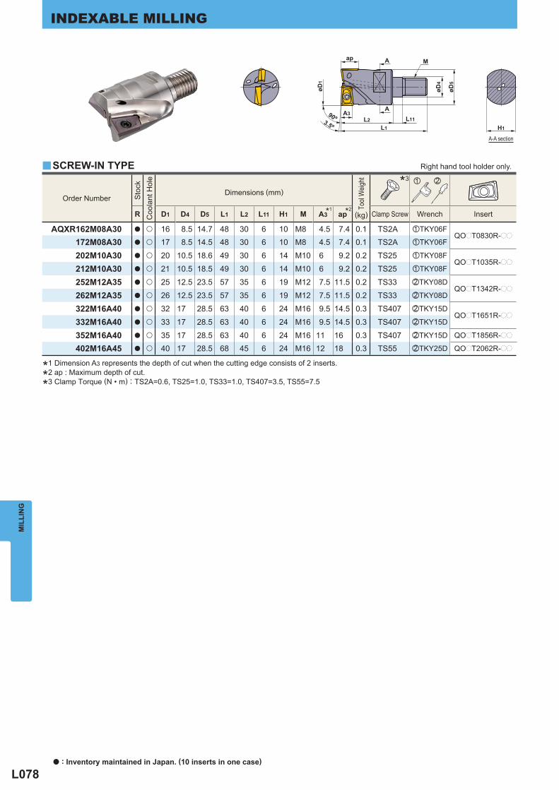
L078
Order Number
Sto
ck
Coo
lant
Hol
e
Dimensions (mm)
Tool
Weig
ht
* 3 z x
R D1 D4 D5 L1 L2 L11 H1 M * 1A3 * 2ap Clamp Screw Wrench Insert (kg)
AQXR162M08A30 a u 16 8.5 14.7 48 30 6 10 M8 4.5 7.4 0.1 TS2A zTKY06FQOpT0830R-pp
172M08A30 a u 17 8.5 14.5 48 30 6 10 M8 4.5 7.4 0.1 TS2A zTKY06F
202M10A30 a u 20 10.5 18.6 49 30 6 14 M10 6 9.2 0.2 TS25 zTKY08FQOpT1035R-pp
212M10A30 a u 21 10.5 18.5 49 30 6 14 M10 6 9.2 0.2 TS25 zTKY08F
252M12A35 a u 25 12.5 23.5 57 35 6 19 M12 7.5 11.5 0.2 TS33 xTKY08DQOpT1342R-pp
262M12A35 a u 26 12.5 23.5 57 35 6 19 M12 7.5 11.5 0.2 TS33 xTKY08D
322M16A40 a u 32 17 28.5 63 40 6 24 M16 9.5 14.5 0.3 TS407 xTKY15DQOpT1651R-pp
332M16A40 a u 33 17 28.5 63 40 6 24 M16 9.5 14.5 0.3 TS407 xTKY15D
352M16A40 a u 35 17 28.5 63 40 6 24 M16 11 16 0.3 TS407 xTKY15D QOpT1856R-pp
QOpT2062R-pp402M16A45 a u 40 17 28.5 68 45 6 24 M16 12 18 0.3 TS55 xTKY25D
y
90º3.5º
øD1
L2L1
A3L11
A
A
ap
øD4
øD5
M
H1
MIL
LIN
GINDEXABLE MILLING
SCREW-IN TYPE Right hand tool holder only.
A-A section
*1 Dimension A3 represents the depth of cut when the cutting edge consists of 2 inserts.
*2 ap : Maximum depth of cut.
*3 Clamp Torque (N • m) : TS2A=0.6, TS25=1.0, TS33=1.0, TS407=3.5, TS55=7.5
a : Inventory maintained in Japan. (10 inserts in one case)
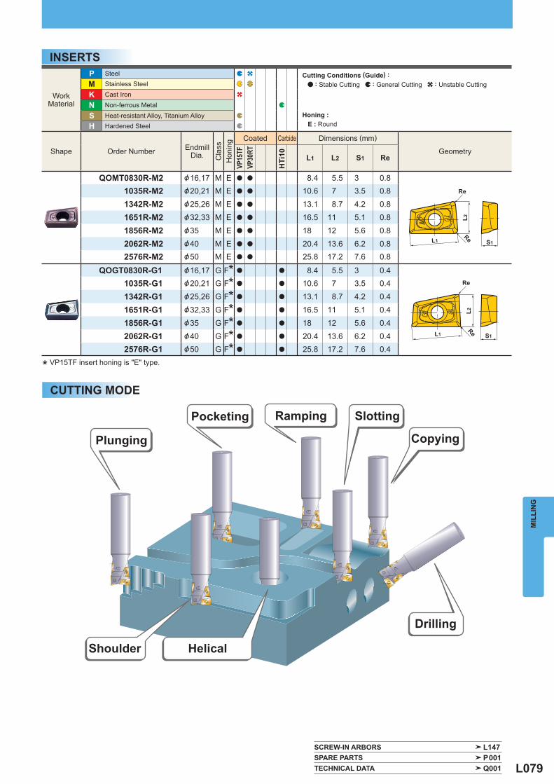
L079
WorkMaterial
P Steel M Stainless Steel
K Cast Iron
N Non-ferrous Metal
S Heat-resistant Alloy, Titanium Alloy H Hardened Steel
Shape Order Number EndmillDia.
Cla
ss
Hon
ing
Coated Carbide Dimensions (mm)
Geometry
VP15
TFVP
30RT
HTi
10 L1 L2 S1 Re
QOMT0830R-M2 &16,17 M E a a 8.4 5.5 3 0.81035R-M2 &20,21 M E a a 10.6 7 3.5 0.8
1342R-M2 &25,26 M E a a 13.1 8.7 4.2 0.8
1651R-M2 &32,33 M E a a 16.5 11 5.1 0.8
1856R-M2 &35 M E a a 18 12 5.6 0.8
2062R-M2 &40 M E a a 20.4 13.6 6.2 0.82576R-M2 &50 M E a a 25.8 17.2 7.6 0.8
QOGT0830R-G1 &16,17 G F* a a 8.4 5.5 3 0.41035R-G1 &20,21 G F* a a 10.6 7 3.5 0.4
1342R-G1 &25,26 G F* a a 13.1 8.7 4.2 0.4
1651R-G1 &32,33 G F* a a 16.5 11 5.1 0.4
1856R-G1 &35 G F* a a 18 12 5.6 0.4
2062R-G1 &40 G F* a a 20.4 13.6 6.2 0.42576R-G1 &50 G F* a a 25.8 17.2 7.6 0.4
SCREW-IN ARBORS L147 SPARE PARTS P001 TECHNICAL DATA Q001
Re S1L1
L2
Re
S1L1
Re
L2
Re
MIL
LIN
G
INSERTS
* VP15TF insert honing is "E" type.
Plunging
Pocketing Ramping Slotting
Copying
Drilling
HelicalShoulder
CUTTING MODE
Cutting Conditions (Guide) : : Stable Cutting : General Cutting : Unstable Cutting
Honing : E : Round
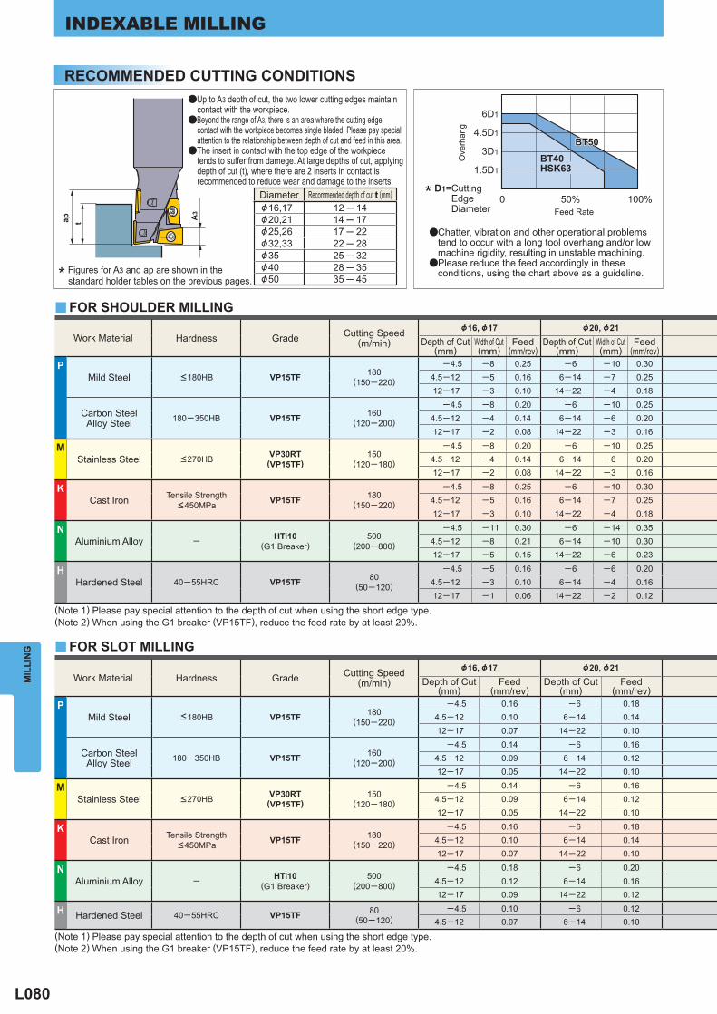
L080
Diameter Recommended depth of cut t (mm) &16,17 12 ─ 14&20,21 14 ─ 17&25,26 17 ─ 22&32,33 22 ─ 28&35 25 ─ 32&40 28 ─ 35&50 35 ─ 45
Work Material Hardness Grade Cutting Speed(m/min)
&16, &17 &20, &21 Depth of Cut
(mm) Width of Cut(mm)
Feed(mm/rev)
Depth of Cut(mm)
Width of Cut(mm)
Feed(mm/rev)
P Mild Steel <180HB VP15TF 180
(150─220)
─4.5 ─8 0.25 ─6 ─10 0.304.5─12 ─5 0.16 6─14 ─7 0.2512─17 ─3 0.10 14─22 ─4 0.18
Carbon SteelAlloy Steel 180─350HB VP15TF 160
(120─200)
─4.5 ─8 0.20 ─6 ─10 0.254.5─12 ─4 0.14 6─14 ─6 0.2012─17 ─2 0.08 14─22 ─3 0.16
M Stainless Steel <270HB VP30RT
(VP15TF)150
(120─180)
─4.5 ─8 0.20 ─6 ─10 0.254.5─12 ─4 0.14 6─14 ─6 0.2012─17 ─2 0.08 14─22 ─3 0.16
K Cast Iron Tensile Strength
<450MPa VP15TF 180(150─220)
─4.5 ─8 0.25 ─6 ─10 0.30 4.5─12 ─5 0.16 6─14 ─7 0.2512─17 ─3 0.10 14─22 ─4 0.18
N Aluminium Alloy ─ HTi10
(G1 Breaker) 500
(200─800)
─4.5 ─11 0.30 ─6 ─14 0.354.5─12 ─8 0.21 6─14 ─10 0.3012─17 ─5 0.15 14─22 ─6 0.23
H Hardened Steel 40─55HRC VP15TF 80
(50─120)
─4.5 ─5 0.16 ─6 ─6 0.204.5─12 ─3 0.10 6─14 ─4 0.1612─17 ─1 0.06 14─22 ─2 0.12
Work Material Hardness Grade Cutting Speed(m/min)
&16, &17 &20, &21 Depth of Cut
(mm) Feed
(mm/rev) Depth of Cut
(mm) Feed
(mm/rev) P
Mild Steel <180HB VP15TF 180(150─220)
─4.5 0.16 ─6 0.184.5─12 0.10 6─14 0.1412─17 0.07 14─22 0.10
Carbon SteelAlloy Steel 180─350HB VP15TF 160
(120─200)
─4.5 0.14 ─6 0.164.5─12 0.09 6─14 0.1212─17 0.05 14─22 0.10
M Stainless Steel <270HB VP30RT
(VP15TF)150
(120─180)
─4.5 0.14 ─6 0.164.5─12 0.09 6─14 0.1212─17 0.05 14─22 0.10
K Cast Iron Tensile Strength
<450MPa VP15TF 180(150─220)
─4.5 0.16 ─6 0.18 4.5─12 0.10 6─14 0.1412─17 0.07 14─22 0.10
N Aluminium Alloy ─ HTi10
(G1 Breaker) 500
(200─800)
─4.5 0.18 ─6 0.204.5─12 0.12 6─14 0.1612─17 0.09 14─22 0.12
H Hardened Steel 40─55HRC VP15TF 80(50─120)
─4.5 0.10 ─6 0.124.5─12 0.07 6─14 0.10
y
y
6D1
4.5D1
3D1
1.5D1
0 50% 100%
BT50BT50BT50
HSK63BT40
ap A3
t
MIL
LIN
GINDEXABLE MILLING
* Figures for A3 and ap are shown in the standard holder tables on the previous pages.
aChatter, vibration and other operational problems tend to occur with a long tool overhang and/or low machine rigidity, resulting in unstable machining.
aPlease reduce the feed accordingly in these conditions, using the chart above as a guideline.
(Note 1) Please pay special attention to the depth of cut when using the short edge type.(Note 2) When using the G1 breaker (VP15TF), reduce the feed rate by at least 20%.
Ove
rhan
g
* D1=Cutting Edge Diameter
RECOMMENDED CUTTING CONDITIONS
FOR SHOULDER MILLING
FOR SLOT MILLING
(Note 1) Please pay special attention to the depth of cut when using the short edge type.(Note 2) When using the G1 breaker (VP15TF), reduce the feed rate by at least 20%.
aUp to A3 depth of cut, the two lower cutting edges maintain contact with the workpiece.
aBeyond the range of A3, there is an area where the cutting edge contact with the workpiece becomes single bladed. Please pay special attention to the relationship between depth of cut and feed in this area.
aThe insert in contact with the top edge of the workpiece tends to suffer from damege. At large depths of cut, applying depth of cut (t), where there are 2 inserts in contact is recommended to reduce wear and damage to the inserts.
Feed Rate
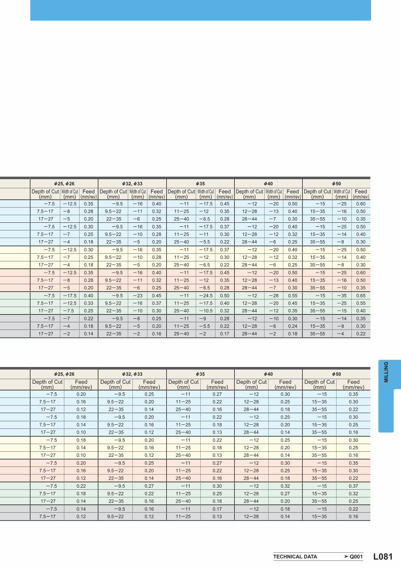
L081
&25, &26 &32, &33 &35 &40 &50 Depth of Cut
(mm) Width of Cut(mm)
Feed(mm/rev)
Depth of Cut(mm)
Width of Cut(mm)
Feed(mm/rev)
Depth of Cut(mm)
Width of Cut(mm)
Feed(mm/rev)
Depth of Cut(mm)
Width of Cut(mm)
Feed(mm/rev)
Depth of Cut(mm)
Width of Cut(mm)
Feed(mm/rev)
─7.5 ─12.5 0.35 ─9.5 ─16 0.40 ─11 ─17.5 0.45 ─12 ─20 0.50 ─15 ─25 0.607.5─17 ─8 0.28 9.5─22 ─11 0.32 11─25 ─12 0.35 12─28 ─13 0.40 15─35 ─16 0.5017─27 ─5 0.20 22─35 ─6 0.25 25─40 ─6.5 0.28 28─44 ─7 0.30 35─55 ─10 0.35
─7.5 ─12.5 0.30 ─9.5 ─16 0.35 ─11 ─17.5 0.37 ─12 ─20 0.40 ─15 ─25 0.507.5─17 ─7 0.25 9.5─22 ─10 0.28 11─25 ─11 0.30 12─28 ─12 0.32 15─35 ─14 0.4017─27 ─4 0.18 22─35 ─5 0.20 25─40 ─5.5 0.22 28─44 ─6 0.25 35─55 ─8 0.30
─7.5 ─12.5 0.30 ─9.5 ─16 0.35 ─11 ─17.5 0.37 ─12 ─20 0.40 ─15 ─25 0.507.5─17 ─7 0.25 9.5─22 ─10 0.28 11─25 ─12 0.30 12─28 ─12 0.32 15─35 ─14 0.4017─27 ─4 0.18 22─35 ─5 0.20 25─40 ─6.5 0.22 28─44 ─6 0.25 35─55 ─8 0.30
─7.5 ─12.5 0.35 ─9.5 ─16 0.40 ─11 ─17.5 0.45 ─12 ─20 0.50 ─15 ─25 0.607.5─17 ─8 0.28 9.5─22 ─11 0.32 11─25 ─12 0.35 12─28 ─13 0.40 15─35 ─16 0.5017─27 ─5 0.20 22─35 ─6 0.25 25─40 ─6.5 0.28 28─44 ─7 0.30 35─55 ─10 0.35
─7.5 ─17.5 0.40 ─9.5 ─23 0.45 ─11 ─24.5 0.50 ─12 ─28 0.55 ─15 ─35 0.657.5─17 ─12.5 0.33 9.5─22 ─16 0.37 11─25 ─17.5 0.40 12─28 ─20 0.45 15─35 ─25 0.5517─27 ─7.5 0.25 22─35 ─10 0.30 25─40 ─10.5 0.32 28─44 ─12 0.35 35─55 ─15 0.40
─7.5 ─7 0.22 ─9.5 ─8 0.25 ─11 ─9 0.28 ─12 ─10 0.30 ─15 ─14 0.357.5─17 ─4 0.18 9.5─22 ─5 0.20 11─25 ─5.5 0.22 12─28 ─6 0.24 15─35 ─8 0.3017─27 ─2 0.14 22─35 ─2 0.16 25─40 ─2 0.17 28─44 ─2 0.18 35─55 ─4 0.22
&25, &26 &32, &33 &35 &40 &50 Depth of Cut
(mm) Feed
(mm/rev) Depth of Cut
(mm) Feed
(mm/rev) Depth of Cut
(mm) Feed
(mm/rev) Depth of Cut
(mm) Feed
(mm/rev) Depth of Cut
(mm) Feed
(mm/rev) ─7.5 0.20 ─9.5 0.25 ─11 0.27 ─12 0.30 ─15 0.35
7.5─17 0.16 9.5─22 0.20 11─25 0.22 12─28 0.25 15─35 0.3017─27 0.12 22─35 0.14 25─40 0.16 28─44 0.18 35─55 0.22
─7.5 0.18 ─9.5 0.20 ─11 0.22 ─12 0.25 ─15 0.307.5─17 0.14 9.5─22 0.16 11─25 0.18 12─28 0.20 15─35 0.2517─27 0.10 22─35 0.12 25─40 0.13 28─44 0.14 35─55 0.16
─7.5 0.18 ─9.5 0.20 ─11 0.22 ─12 0.25 ─15 0.307.5─17 0.14 9.5─22 0.16 11─25 0.18 12─28 0.20 15─35 0.2517─27 0.10 22─35 0.12 25─40 0.13 28─44 0.14 35─55 0.16
─7.5 0.20 ─9.5 0.25 ─11 0.27 ─12 0.30 ─15 0.357.5─17 0.16 9.5─22 0.20 11─25 0.22 12─28 0.25 15─35 0.3017─27 0.12 22─35 0.14 25─40 0.16 28─44 0.18 35─55 0.22
─7.5 0.22 ─9.5 0.27 ─11 0.30 ─12 0.32 ─15 0.377.5─17 0.18 9.5─22 0.22 11─25 0.25 12─28 0.27 15─35 0.3217─27 0.14 22─35 0.16 25─40 0.18 28─44 0.20 35─55 0.25
─7.5 0.14 ─9.5 0.16 ─11 0.17 ─12 0.18 ─15 0.227.5─17 0.12 9.5─22 0.12 11─25 0.13 12─28 0.14 15─35 0.16
TECHNICAL DATA Q001
MIL
LIN
G
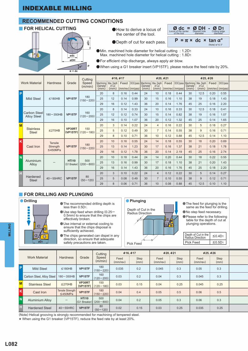
L082
Work Material Hardness Grade Cutting Speed(m/min)
&16, &17 &20, &21 &25, &26 MachiningDiameter(mm)
Max. Depthof Cut
(mm)
Feed
(mm/rev)
DOC/pass
(mm/pass)
MachiningDiameter(mm)
Max. Depthof Cut
(mm)
Feed
(mm/rev)
DOC/pass
(mm/pass)
MachiningDiameter(mm)
Max. Depthof Cut
(mm)
Feed
(mm/rev)
DOC/pass
(mm/pass)
P Mild Steel <180HB VP15TF 180
(150─220)
20 8 0.16 0.44 24 10 0.18 0.44 30 12.5 0.20 0.55
25 12 0.14 0.99 30 15 0.16 1.10 38 19 0.18 1.43
29 16 0.12 1.43 36 20 0.14 1.76 45 25 0.16 2.20
Carbon SteelAlloy Steel 180─350HB VP15TF 160
(120─200)
20 8 0.14 0.33 24 10 0.16 0.33 30 12.5 0.18 0.41
25 12 0.12 0.74 30 15 0.14 0.82 38 19 0.16 1.07
29 16 0.10 1.07 36 20 0.12 1.32 45 25 0.14 1.65
M Stainless
Steel <270HB VP30RT(VP15TF)
150(120─180)
20 3 0.14 0.22 24 4 0.16 0.22 30 5 0.18 0.27
25 5 0.12 0.49 30 7 0.14 0.55 38 9 0.16 0.71
29 8 0.10 0.71 36 10 0.12 0.88 45 12.5 0.14 1.10
K Cast Iron
Tensile Strength <450MPa
VP15TF 180(150─220)
20 10 0.16 0.55 24 14 0.18 0.55 30 18 0.20 0.69
25 13 0.14 1.23 30 17 0.16 1.37 38 21 0.18 1.78
29 16 0.12 1.78 36 20 0.14 2.19 45 25 0.16 2.74
N Aluminium
Alloy ─ HTi10 (G1 Breaker)
500(200─800)
20 10 0.18 0.44 24 14 0.20 0.44 30 18 0.22 0.55
25 13 0.16 0.99 30 17 0.18 1.10 38 21 0.20 1.43
29 16 0.14 1.43 36 20 0.16 1.76 45 25 0.18 2.20
H Hardened
Steel 40─55HRC VP15TF 80(50─120)
20 3 0.10 0.22 24 4 0.12 0.22 30 5 0.14 0.27
25 5 0.08 0.49 30 7 0.10 0.55 38 9 0.12 0.71
29 8 0.06 0.71 36 10 0.08 0.88 45 12.5 0.10 1.10
Work Material Hardness Grade Cutting Speed(m/min)
&16, &17 &20, &21 &25, &26
Feed(mm/rev)
Step(mm)
Feed(mm/rev)
Step(mm)
Feed(mm/rev)
Step(mm)
P Mild Steel <180HB VP15TF 180(150─220) 0.035 0.2 0.045 0.3 0.05 0.3
Carbon Steel, Alloy Steel 180─350HB VP15TF 160(120─200) 0.03 0.2 0.04 0.3 0.045 0.3
M Stainless Steel <270HB VP30RT(VP15TF)
150(120─180) 0.03 0.15 0.04 0.25 0.045 0.25
K Cast Iron Tensile Strength <450MPa VP15TF 180
(150─220) 0.04 0.4 0.05 0.5 0.06 0.5
N Aluminium Alloy ─ HTi10 (G1 Breaker)
500(200─800) 0.04 0.2 0.05 0.3 0.06 0.3
H Hardened Steel 40─55HRC VP15TF 80(50─120) 0.02 0.15 0.03 0.25 0.035 0.25
ø dc = ø DH - ø D1
P = ) × dc × tan %°
y
a
y
a
Depth of Cut in the Radius Direction <0.4D1
Pick Feed <0.5D1
øDH
øD1
ødc
P
) × dc%°
øD1
MIL
LIN
GINDEXABLE MILLING
aMin. machined hole diameter for helical cutting : 1.2D1 Max. machined hole diameter for helical cutting : 1.8D1
aFor effi cient chip discharge, always apply air blow.aWhen using a G1 breaker insert (VP15TF), please reduce the feed rate by 20%.
aHow to derive a locus of the center of the tool.
aDepth of cut for each pass.(Note) %°< 3°
Locus of the centerof the tool
Desired holediameter
Cutting edgediameter
aThe recommended drilling depth is less than 0.5D1.
aUse step feed when drilling (0.25─ 0.5mm) to ensure that the chips are effectively broken.
aUse internal or external cooling to ensure that the chips disposal is suffi ciently achieved.
aThe chips generated can dispel in any direction, so ensure that adequate safety precautions are taken.
aThe feed for plunging is the same as the feed for drilling.
aNo step feed necessary.aPlease refer to the following
table for the depth of cut at plunging operations.
Pick Feed
Depth of Cut in the Radius Direction
(Note) Helical grooving is strongly recommended for machining of tempered steel.
* When using the G1 breaker (VP15TF), reduce the feed rate by at least 20%.
RECOMMENDED CUTTING CONDITIONSFOR HELICAL CUTTING
FOR DRILLING AND PLUNGINGDrilling Plunging
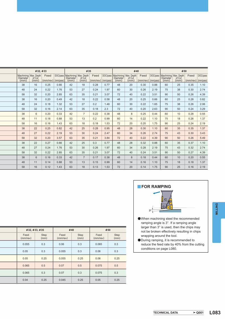
L083
&32, &33 &35 &40 &50 MachiningDiameter(mm)
Max. Depthof Cut(mm)
Feed
(mm/rev)
DOC/pass
(mm/pass)
MachiningDiameter(mm)
Max. Depthof Cut(mm)
Feed
(mm/rev)
DOC/pass
(mm/pass)
MachiningDiameter(mm)
Max. Depthof Cut(mm)
Feed
(mm/rev)
DOC/pass
(mm/pass)
MachiningDiameter(mm)
Max. Depthof Cut(mm)
Feed
(mm/rev)
DOC/pass
(mm/pass)
38 16 0.25 0.66 42 18 0.28 0.77 48 20 0.30 0.88 60 25 0.35 1.10
48 24 0.22 1.76 53 27 0.24 1.97 60 30 0.26 2.19 75 38 0.30 2.74
58 32 0.20 2.85 63 35 0.21 3.07 72 40 0.22 3.51 90 50 0.26 4.39
38 16 0.20 0.49 42 18 0.22 0.58 48 20 0.25 0.66 60 25 0.28 0.82
48 24 0.18 1.32 53 27 0.2 1.48 60 30 0.22 1.65 75 38 0.26 2.06
58 32 0.16 2.14 63 35 0.18 2.3 72 40 0.20 2.63 90 50 0.24 3.29
38 6 0.20 0.33 42 7 0.22 0.38 48 8 0.25 0.44 60 10 0.28 0.55
48 11 0.18 0.88 53 13 0.2 0.99 60 14 0.22 1.10 75 18 0.26 1.37
58 16 0.16 1.43 63 18 0.18 1.53 72 20 0.20 1.75 90 25 0.24 2.19
38 22 0.25 0.82 42 25 0.28 0.95 48 28 0.30 1.10 60 35 0.35 1.37
48 27 0.22 2.19 53 30 0.24 2.47 60 34 0.26 2.74 75 43 0.30 3.43
58 32 0.20 3.57 63 35 0.21 3.84 72 40 0.22 4.39 90 50 0.26 5.49
38 22 0.27 0.66 42 25 0.3 0.77 48 28 0.32 0.88 60 35 0.37 1.10
48 27 0.24 1.76 53 30 0.26 1.97 60 34 0.28 2.19 75 43 0.32 2.74
58 32 0.22 2.85 63 35 0.21 3.07 72 40 0.24 3.51 90 50 0.27 4.39
38 6 0.16 0.33 42 7 0.17 0.38 48 8 0.18 0.44 60 10 0.20 0.55
48 11 0.14 0.88 53 13 0.15 0.99 60 14 0.16 1.10 75 18 0.18 1.37
58 16 0.12 1.43 63 18 0.13 1.53 72 20 0.14 1.75 90 25 0.16 2.19
&32, &33, &35 &40 &50
Feed(mm/rev)
Step(mm)
Feed(mm/rev)
Step(mm)
Feed(mm/rev)
Step(mm)
0.055 0.3 0.06 0.3 0.065 0.3
0.05 0.3 0.055 0.3 0.06 0.3
0.05 0.25 0.055 0.25 0.06 0.25
0.065 0.5 0.07 0.5 0.075 0.5
0.065 0.3 0.07 0.3 0.075 0.3
0.04 0.25 0.045 0.25 0.05 0.25
y
TECHNICAL DATA Q001
3°
MIL
LIN
GaWhen machining steel the recommended
ramping angle is 3°. If a ramping angle larger than 3° is used, then the chips may not be broken effectively resulting in chips wrapping around the tool.
aDuring ramping, it is recommended to reduce the feed rate by 40% from the cutting conditions on page L080.
FOR RAMPING
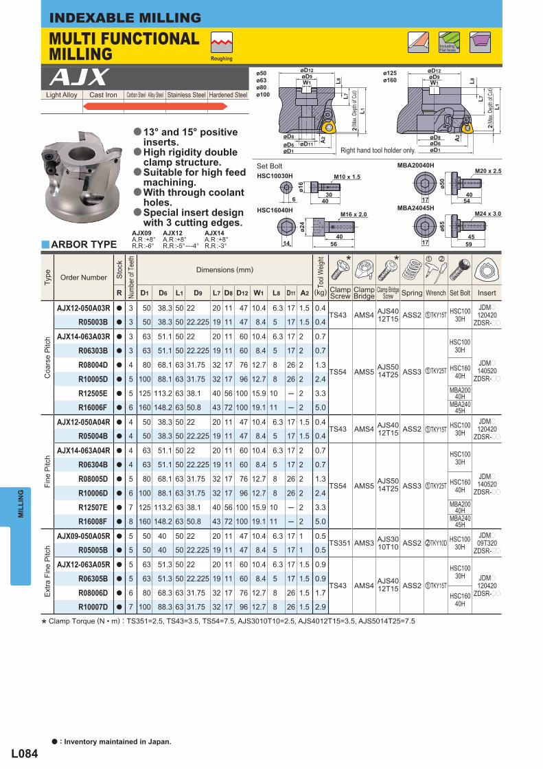
L084
Light Alloy Cast Iron Carbon Steel · Alloy Steel Stainless Steel Hardened Steel AJX
Type
Order Number
Sto
ck
Numb
er of
Tee
th
Dimensions (mm)
Tool
Weig
ht
* * z x
R D1 D6 L1 D9 L7 D8 D12 W1 L8 D11 A2 ClampScrew
ClampBridge
Clamp BridgeScrew Spring Wrench Set Bolt Insert (kg)
Coa
rse
Pitc
h
AJX12-050A03R a 3 50 38.3 50 22 20 11 47 10.4 6.3 17 1.5 0.4TS43 AMS4 AJS40
12T15 ASS2 zTKY15T HSC10030H
JDMp
120420ZDSR-ppR05003B a 3 50 38.3 50 22.225 19 11 47 8.4 5 17 1.5 0.4
AJX14-063A03R a 3 63 51.1 50 22 20 11 60 10.4 6.3 17 2 0.7
TS54 AMS5AJS5014T25 ASS3 zTKY25T
HSC10030H
JDMp
140520ZDSR-pp
R06303B a 3 63 51.1 50 22.225 19 11 60 8.4 5 17 2 0.7
R08004D a 4 80 68.1 63 31.75 32 17 76 12.7 8 26 2 1.3 HSC16040HR10005D a 5 100 88.1 63 31.75 32 17 96 12.7 8 26 2 2.4
R12505E a 5 125 113.2 63 38.1 40 56 100 15.9 10 ─ 2 3.3 MBA20040H
R16006F a 6 160 148.2 63 50.8 43 72 100 19.1 11 ─ 2 5.0 MBA24045H
Fine
Pitc
h
AJX12-050A04R a 4 50 38.3 50 22 20 11 47 10.4 6.3 17 1.5 0.4TS43 AMS4 AJS40
12T15 ASS2 zTKY15T HSC10030H
JDMp
120420ZDSR-ppR05004B a 4 50 38.3 50 22.225 19 11 47 8.4 5 17 1.5 0.4
AJX14-063A04R a 4 63 51.1 50 22 20 11 60 10.4 6.3 17 2 0.7
TS54 AMS5AJS5014T25 ASS3 zTKY25T
HSC10030H
JDMp
140520ZDSR-pp
R06304B a 4 63 51.1 50 22.225 19 11 60 8.4 5 17 2 0.7
R08005D a 5 80 68.1 63 31.75 32 17 76 12.7 8 26 2 1.3 HSC16040HR10006D a 6 100 88.1 63 31.75 32 17 96 12.7 8 26 2 2.4
R12507E a 7 125 113.2 63 38.1 40 56 100 15.9 10 ─ 2 3.3 MBA20040H
R16008F a 8 160 148.2 63 50.8 43 72 100 19.1 11 ─ 2 5.0 MBA24045H
Ext
ra F
ine
Pitc
h
AJX09-050A05R a 5 50 40 50 22 20 11 47 10.4 6.3 17 1 0.5TS351 AMS3 AJS30
10T10 ASS2 xTKY10D HSC10030H
JDMp
09T320ZDSR-ppR05005B a 5 50 40 50 22.225 19 11 47 8.4 5 17 1 0.5
AJX12-063A05R a 5 63 51.3 50 22 20 11 60 10.4 6.3 17 1.5 0.9
TS43 AMS4 AJS4012T15 ASS2 zTKY15T
HSC10030H JDMp
120420ZDSR-pp
R06305B a 5 63 51.3 50 22.225 19 11 60 8.4 5 17 1.5 0.9
R08006D a 6 80 68.3 63 31.75 32 17 76 12.7 8 26 1.5 1.7 HSC16040HR10007D a 7 100 88.3 63 31.75 32 17 96 12.7 8 26 1.5 2.9
y
AJX09A.R :+8°R.R :-6°
AJX12A.R :+8°R.R :-5°─ -4°
AJX14A.R :+8°R.R :-3°
ø50ø63ø80ø100
ø125ø160
øD8
A2
W1øD9
øD6 øD11øD1
L8L7
L1
A2
W1øD9
øD6øD8
øD1
L8L7
L1
M24 x 3.0
4559
ø65
17
M20 x 2.5
4054
ø50
17
14
ø24
56
M16 x 2.0
40
6
ø16
4030
M10 x 1.5
MBA24045H
MBA20040H
HSC16040H
HSC10030H
2 2
øD12 øD12
MIL
LIN
GINDEXABLE MILLING
* Clamp Torque (N • m) : TS351=2.5, TS43=3.5, TS54=7.5, AJS3010T10=2.5, AJS4012T15=3.5, AJS5014T25=7.5
ARBOR TYPE
Right hand tool holder only.
MULTI FUNCTIONAL MILLING Roughing
Including Flat faces
( Max
. Dep
th of
Cut)
( Max
. Dep
th of
Cut)
13° and 15° positive inserts.High rigidity double clamp structure.Suitable for high feed machining.With through coolant holes.Special insert design with 3 cutting edges.
a
a
a
a
a
Set Bolt
a : Inventory maintained in Japan.
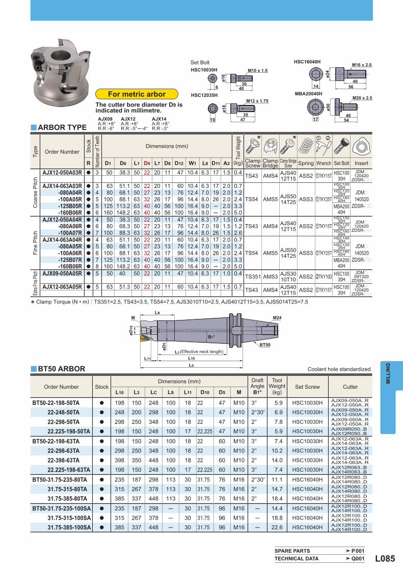
L085
Order Number Stock Dimensions (mm) Draft
Angle B1°
ToolWeight
(kg) Set Screw Cutter
L10 L3 LC LS L11 D10 D5 M
BT50-22-198-50TA a 198 150 248 100 18 22 47 M10 3° 5.9 HSC10030H AJX09-050A..RAJX12-050A..R
22-248-50TA a 248 200 298 100 18 22 47 M10 2°30′ 6.9 HSC10030H AJX09-050A..RAJX12-050A..R
22-298-50TA a 298 250 348 100 18 22 47 M10 2° 7.8 HSC10030H AJX09-050A..RAJX12-050A..R
22.225-198-50TA a 198 150 248 100 17 22.225 47 M10 3° 5.9 HSC10030H AJX09R050..BAJX12R050..B
BT50-22-198-63TA a 198 150 248 100 18 22 60 M10 3° 7.4 HSC10030H AJX12-063A..RAJX14-063A..R
22-298-63TA a 298 250 348 100 18 22 60 M10 2° 10.2 HSC10030H AJX12-063A..RAJX14-063A..R
22-398-63TA a 398 350 448 100 18 22 60 M10 2° 14.0 HSC10030H AJX12-063A..RAJX14-063A..R
22.225-198-63TA a 198 150 248 100 17 22.225 60 M10 3° 7.4 HSC10030H AJX12R063..BAJX14R063..B
BT50-31.75-235-80TA a 235 187 298 113 30 31.75 76 M16 2°30′ 11.1 HSC16040H AJX12R080..DAJX14R080..D
31.75-315-80TA a 315 267 378 113 30 31.75 76 M16 2° 14.7 HSC16040H AJX12R080..DAJX14R080..D
31.75-385-80TA a 385 337 448 113 30 31.75 76 M16 2° 18.4 HSC16040H AJX12R080..DAJX14R080..D
BT50-31.75-235-100SA a 235 187 298 ─ 30 31.75 96 M16 ─ 14.4 HSC16040H AJX12R100..DAJX14R100..D
31.75-315-100SA a 315 267 378 ─ 30 31.75 96 M16 ─ 18.8 HSC16040H AJX12R100..DAJX14R100..D
31.75-385-100SA a 385 337 448 ─ 30 31.75 96 M16 ─ 22.6 HSC16040H AJX12R100..DAJX14R100..D
Type
Order Number
Sto
ck
Numb
er of
Tee
th
Dimensions (mm)
Tool
Weig
ht
* * z x
R D1 D6 L1 D9 L7 D8 D12 W1 L8 D11 A2 ClampScrew
ClampBridge
Clamp BridgeScrew Spring Wrench Set Bolt Insert (kg)
Coa
rse
Pitc
h
AJX12-050A03R a 3 50 38.3 50 22 20 11 47 10.4 6.3 17 1.5 0.4 TS43 AMS4 AJS4012T15 ASS2 zTKY15T HSC100
30HJDMp120420
ZDSR-pp
AJX14-063A03R a 3 63 51.1 50 22 20 11 60 10.4 6.3 17 2.0 0.7
TS54 AMS5 AJS5014T25 ASS3 zTKY25T
HSC10030H
JDMp
140520ZDSR-pp
-080A04R a 4 80 68.1 50 27 23 13 76 12.4 7.0 19 2.0 1.2 HSC12035H
-100A05R a 5 100 88.1 63 32 26 17 96 14.4 8.0 26 2.0 2.4 HSC16040H
-125B05R a 5 125 113.2 63 40 40 56 100 16.4 9.0 ─ 2.0 3.3 MBA20040H-160B06R a 6 160 148.2 63 40 40 56 100 16.4 9.0 ─ 2.0 5.0
Fine
Pitc
h
AJX12-050A04R a 4 50 38.3 50 22 20 11 47 10.4 6.3 17 1.5 0.4TS43 AMS4 AJS40
12T15 ASS2 zTKY15THSC100
30H JDMp120420
ZDSR-pp-080A06R a 6 80 68.3 50 27 23 13 76 12.4 7.0 19 1.5 1.2 HSC120
35H-100A07R a 7 100 88.3 63 32 26 17 96 14.4 8.0 26 1.5 2.6 HSC160
40HAJX14-063A04R a 4 63 51.1 50 22 20 11 60 10.4 6.3 17 2.0 0.7
TS54 AMS5 AJS5014T25 ASS3 zTKY25T
HSC10030H
JDMp
140520ZDSR-pp
-080A05R a 5 80 68.1 50 27 23 13 76 12.4 7.0 19 2.0 1.2 HSC12035H
-100A06R a 6 100 88.1 63 32 26 17 96 14.4 8.0 26 2.0 2.4 HSC16040H
-125B07R a 7 125 113.2 63 40 40 56 100 16.4 9.0 ─ 2.0 3.3 MBA20040H-160B08R a 8 160 148.2 63 40 40 56 100 16.4 9.0 ─ 2.0 5.0
Extra
Fine
Pitch
AJX09-050A05R a 5 50 40 50 22 20 11 47 10.4 6.3 17 1.0 0.4 TS351 AMS3 AJS3010T10 ASS2 xTKY10D HSC100
30HJDMp
09T320ZDSR-pp
AJX12-063A05R a 5 63 51.3 50 22 20 11 60 10.4 6.3 17 1.5 0.7 TS43 AMS4 AJS4012T15 ASS2 zTKY15T HSC100
30HJDMp120420
ZDSR-pp
y
y
AJX09A.R :+8°R.R :-6°
AJX12A.R :+8°R.R :-5°─ -4°
AJX14A.R :+8°R.R :-3°
SPARE PARTS P001 TECHNICAL DATA Q001
M20 x 2.5
4054
ø50
17
14
ø24
56
M16 x 2.0
40ø16
4030
M10 x 1.5
MBA20040H
HSC16040HHSC10030H
HSC12035HM12 x 1.75
ø18
1035
47
6
øD10
øD5
M M24
BT50
Ls
L3
L10
LcL11
B1°
MIL
LIN
G
* Clamp Torque (N • m) : TS351=2.5, TS43=3.5, TS54=7.5, AJS3010T10=2.5, AJS4012T15=3.5, AJS5014T25=7.5
Coolant hole standardized.
(Effective neck length)
For metric arborThe cutter bore diameter D9 is indicated in millimetre.
ARBOR TYPE
Set Bolt
BT50 ARBOR
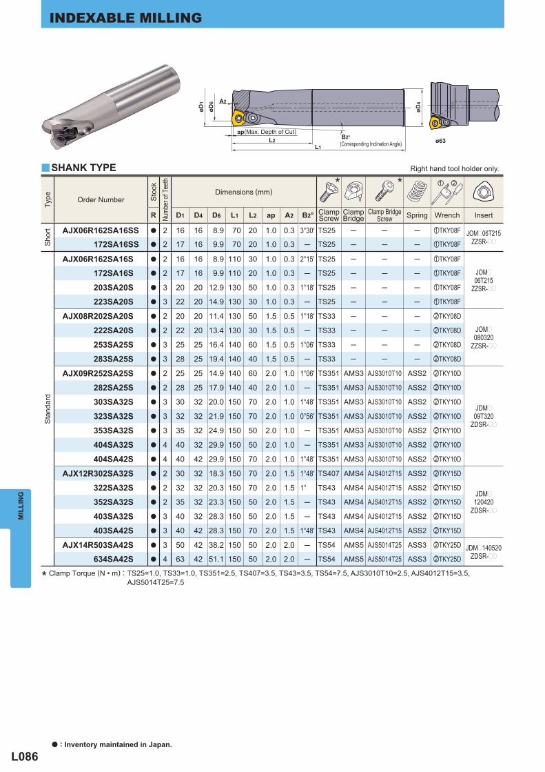
L086
Type
Order Number
Sto
ck
Numb
er of
Tee
th
Dimensions (mm)* * z x
R D1 D4 D6 L1 L2 ap A2 B2° ClampScrew
ClampBridge
Clamp BridgeScrew Spring Wrench Insert
Sho
rt
AJX06R162SA16SS a 2 16 16 8.9 70 20 1.0 0.3 3°30′ TS25 ─ ─ ─ zTKY08F JOMp06T215ZZSR-pp172SA16SS a 2 17 16 9.9 70 20 1.0 0.3 ─ TS25 ─ ─ ─ zTKY08F
Sta
ndar
d
AJX06R162SA16S a 2 16 16 8.9 110 30 1.0 0.3 2°15′ TS25 ─ ─ ─ zTKY08F
JOMp
06T215ZZSR-pp
172SA16S a 2 17 16 9.9 110 20 1.0 0.3 ─ TS25 ─ ─ ─ zTKY08F
203SA20S a 3 20 20 12.9 130 50 1.0 0.3 1°18′ TS25 ─ ─ ─ zTKY08F
223SA20S a 3 22 20 14.9 130 30 1.0 0.3 ─ TS25 ─ ─ ─ zTKY08F
AJX08R202SA20S a 2 20 20 11.4 130 50 1.5 0.5 1°18′ TS33 ─ ─ ─ xTKY08D
JOMp
080320ZZSR-pp
222SA20S a 2 22 20 13.4 130 30 1.5 0.5 ─ TS33 ─ ─ ─ xTKY08D
253SA25S a 3 25 25 16.4 140 60 1.5 0.5 1°06′ TS33 ─ ─ ─ xTKY08D
283SA25S a 3 28 25 19.4 140 40 1.5 0.5 ─ TS33 ─ ─ ─ xTKY08D
AJX09R252SA25S a 2 25 25 14.9 140 60 2.0 1.0 1°06′ TS351 AMS3 AJS3010T10 ASS2 xTKY10D
JDMp
09T320ZDSR-pp
282SA25S a 2 28 25 17.9 140 40 2.0 1.0 ─ TS351 AMS3 AJS3010T10 ASS2 xTKY10D
303SA32S a 3 30 32 20.0 150 70 2.0 1.0 1°48′ TS351 AMS3 AJS3010T10 ASS2 xTKY10D
323SA32S a 3 32 32 21.9 150 70 2.0 1.0 0°56′ TS351 AMS3 AJS3010T10 ASS2 xTKY10D
353SA32S a 3 35 32 24.9 150 50 2.0 1.0 ─ TS351 AMS3 AJS3010T10 ASS2 xTKY10D
404SA32S a 4 40 32 29.9 150 50 2.0 1.0 ─ TS351 AMS3 AJS3010T10 ASS2 xTKY10D
404SA42S a 4 40 42 29.9 150 70 2.0 1.0 1°48′ TS351 AMS3 AJS3010T10 ASS2 xTKY10D
AJX12R302SA32S a 2 30 32 18.3 150 70 2.0 1.5 1°48′ TS407 AMS4 AJS4012T15 ASS2 xTKY15D
JDMp
120420ZDSR-pp
322SA32S a 2 32 32 20.3 150 70 2.0 1.5 1° TS43 AMS4 AJS4012T15 ASS2 xTKY15D
352SA32S a 2 35 32 23.3 150 50 2.0 1.5 ─ TS43 AMS4 AJS4012T15 ASS2 xTKY15D
403SA32S a 3 40 32 28.3 150 50 2.0 1.5 ─ TS43 AMS4 AJS4012T15 ASS2 xTKY15D
403SA42S a 3 40 42 28.3 150 70 2.0 1.5 1°48′ TS43 AMS4 AJS4012T15 ASS2 xTKY15D
AJX14R503SA42S a 3 50 42 38.2 150 50 2.0 2.0 ─ TS54 AMS5 AJS5014T25 ASS3 xTKY25D JDMp140520ZDSR-pp634SA42S a 4 63 42 51.1 150 50 2.0 2.0 ─ TS54 AMS5 AJS5014T25 ASS3 xTKY25D
y
A2
L2B2°
L1
øD1
øD6
øD4
ap
MIL
LIN
GINDEXABLE MILLING
* Clamp Torque (N • m) : TS25=1.0, TS33=1.0, TS351=2.5, TS407=3.5, TS43=3.5, TS54=7.5, AJS3010T10=2.5, AJS4012T15=3.5, AJS5014T25=7.5
ø63
SHANK TYPE Right hand tool holder only.
(Max. Depth of Cut)
(Corresponding Inclination Angle)
a : Inventory maintained in Japan.
L087
Type
Order Number
Sto
ck
Numb
er of
Tee
th
Dimensions (mm)* * z x
R D1 D4 D6 L1 L2 ap A2 B2° ClampScrew
ClampBridge
Clamp BridgeScrew Spring Wrench Insert
Long
AJX06R162SA16L a 2 16 16 8.9 150 70 1.0 0.3 0°56′ TS25 ─ ─ ─ zTKY08F
JOMp
06T215ZZSR-pp
172SA16L a 2 17 16 9.9 150 20 1.0 0.3 ─ TS25 ─ ─ ─ zTKY08F
203SA20L a 3 20 20 12.9 180 100 1.0 0.3 0°38′ TS25 ─ ─ ─ zTKY08F
223SA20L a 3 22 20 14.9 180 30 1.0 0.3 ─ TS25 ─ ─ ─ zTKY08F
AJX08R202SA20L a 2 20 20 11.4 180 100 1.5 0.5 0°36′ TS33 ─ ─ ─ xTKY08D
JOMp
080320ZZSR-pp
222SA20L a 2 22 20 13.4 180 30 1.5 0.5 ─ TS33 ─ ─ ─ xTKY08D
253SA25L a 3 25 25 16.4 200 120 1.5 0.5 0°32′ TS33 ─ ─ ─ xTKY08D
283SA25L a 3 28 25 19.4 200 40 1.5 0.5 ─ TS33 ─ ─ ─ xTKY08D
AJX09R252SA25L a 2 25 25 14.9 200 120 2.0 1.0 0°30′ TS351 AMS3 AJS3010T10 ASS2 xTKY10D
JDMp
09T320ZDSR-pp
282SA25L a 2 28 25 17.9 200 40 2.0 1.0 ─ TS351 AMS3 AJS3010T10 ASS2 xTKY10D
303SA32L a 3 30 32 20.0 200 120 2.0 1.0 1°02′ TS351 AMS3 AJS3010T10 ASS2 xTKY10D
323SA32L a 3 32 32 21.9 200 120 2.0 1.0 0°32′ TS351 AMS3 AJS3010T10 ASS2 xTKY10D
353SA32L a 3 35 32 24.9 200 50 2.0 1.0 ─ TS351 AMS3 AJS3010T10 ASS2 xTKY10D
404SA32L a 4 40 32 29.9 250 50 2.0 1.0 ─ TS351 AMS3 AJS3010T10 ASS2 xTKY10D
404SA42L a 4 40 42 29.9 250 70 2.0 1.0 1°48′ TS351 AMS3 AJS3010T10 ASS2 xTKY10D
AJX12R302SA32L a 2 30 32 18.3 200 120 2.0 1.5 1° TS407 AMS4 AJS4012T15 ASS2 xTKY15D
JDMp
120420ZDSR-pp
322SA32L a 2 32 32 20.3 200 120 2.0 1.5 0°36′ TS43 AMS4 AJS4012T15 ASS2 xTKY15D
352SA32L a 2 35 32 23.3 200 50 2.0 1.5 ─ TS43 AMS4 AJS4012T15 ASS2 xTKY15D
403SA32L a 3 40 32 28.3 250 50 2.0 1.5 ─ TS43 AMS4 AJS4012T15 ASS2 xTKY15D
403SA42L a 3 40 42 28.3 250 70 2.0 1.5 1°48′ TS43 AMS4 AJS4012T15 ASS2 xTKY25D
AJX14R503SA42L a 3 50 42 38.1 250 50 2.0 2.0 ─ TS54 AMS5 AJS5014T25 ASS3 xTKY25D JDMp140520ZDSR-pp634SA42L a 4 63 42 51.1 250 50 2.0 2.0 ─ TS54 AMS5 AJS5014T25 ASS3 xTKY25D
Ext
ra L
ong
AJX06R162SA16EL a 2 16 16 8.9 200 100 1.0 0.3 0°38′ TS25 ─ ─ ─ zTKY08F JOMp06T215ZZSR-pp172SA16EL a 2 17 16 9.9 200 20 1.0 0.3 ─ TS25 ─ ─ ─ zTKY08F
AJX08R202SA20EL a 2 20 20 11.4 250 130 1.5 0.5 0°30′ TS33 ─ ─ ─ xTKY08D JOMp080320ZZSR-pp222SA20EL a 2 22 20 13.4 250 30 1.5 0.5 ─ TS33 ─ ─ ─ xTKY08D
AJX09R252SA25EL a 2 25 25 14.9 300 180 2.0 1.0 0°18′ TS351 AMS3 AJS3010T10 ASS2 xTKY10D JDMp09T320ZDSR-pp282SA25EL a 2 28 25 17.9 300 40 2.0 1.0 ─ TS351 AMS3 AJS3010T10 ASS2 xTKY10D
AJX12R302SA32EL a 2 30 32 18.3 300 180 2.0 1.5 0°42′ TS407 AMS4 AJS4012T15 ASS2 xTKY15D
JDMp
120420ZDSR-pp
322SA32EL a 2 32 32 20.3 300 180 2.0 1.5 0°24′ TS43 AMS4 AJS4012T15 ASS2 xTKY15D
352SA32EL a 2 35 32 23.3 300 50 2.0 1.5 ─ TS43 AMS4 AJS4012T15 ASS2 xTKY15D
402SA32EL a 2 40 32 28.3 350 50 2.0 1.5 ─ TS43 AMS4 AJS4012T15 ASS2 xTKY15D
402SA42EL a 2 40 42 28.3 350 70 2.0 1.5 1°48′ TS43 AMS4 AJS4012T15 ASS2 xTKY15D
SPARE PARTS P001 TECHNICAL DATA Q001
MIL
LIN
G
* Clamp Torque (N • m) : TS25=1.0, TS33=1.0, TS351=2.5, TS407=3.5, TS43=3.5, TS54=7.5, AJS3010T10=2.5, AJS4012T15=3.5, AJS5014T25=7.5
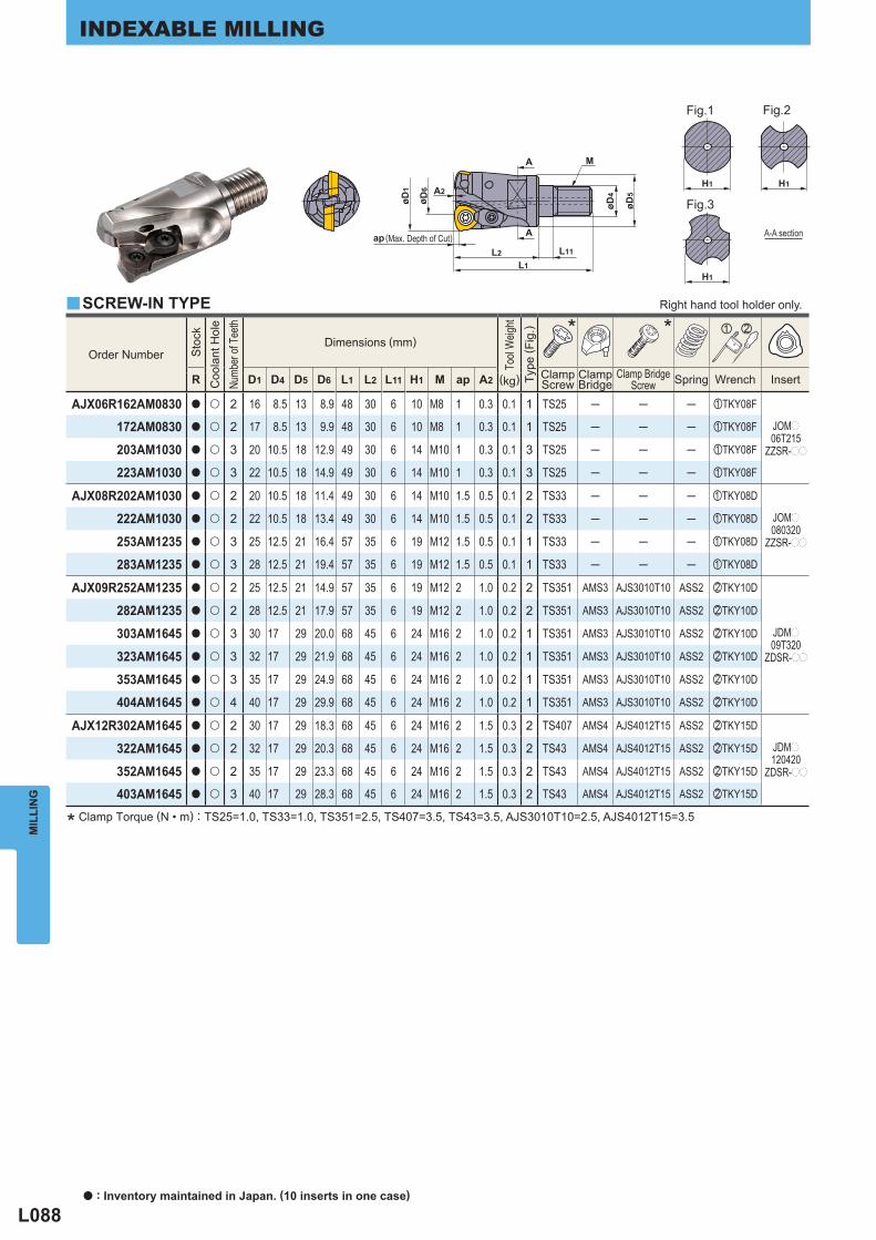
L088
Order Number
Sto
ck
Coo
lant
Hol
e
Numb
er of
Tee
th
Dimensions (mm)
Tool
Weig
ht
Type
( Fig
.)
* * z x
R D1 D4 D5 D6 L1 L2 L11 H1 M ap A2 ClampScrew
ClampBridge
Clamp BridgeScrew Spring Wrench Insert (kg)
AJX06R162AM0830 a u 2 16 8.5 13 8.9 48 30 6 10 M8 1 0.3 0.1 1 TS25 ─ ─ ─ zTKY08F
JOMp
06T215ZZSR-pp
172AM0830 a u 2 17 8.5 13 9.9 48 30 6 10 M8 1 0.3 0.1 1 TS25 ─ ─ ─ zTKY08F
203AM1030 a u 3 20 10.5 18 12.9 49 30 6 14 M10 1 0.3 0.1 3 TS25 ─ ─ ─ zTKY08F
223AM1030 a u 3 22 10.5 18 14.9 49 30 6 14 M10 1 0.3 0.1 3 TS25 ─ ─ ─ zTKY08F
AJX08R202AM1030 a u 2 20 10.5 18 11.4 49 30 6 14 M10 1.5 0.5 0.1 2 TS33 ─ ─ ─ zTKY08D
JOMp
080320ZZSR-pp
222AM1030 a u 2 22 10.5 18 13.4 49 30 6 14 M10 1.5 0.5 0.1 2 TS33 ─ ─ ─ zTKY08D
253AM1235 a u 3 25 12.5 21 16.4 57 35 6 19 M12 1.5 0.5 0.1 1 TS33 ─ ─ ─ zTKY08D
283AM1235 a u 3 28 12.5 21 19.4 57 35 6 19 M12 1.5 0.5 0.1 1 TS33 ─ ─ ─ zTKY08D
AJX09R252AM1235 a u 2 25 12.5 21 14.9 57 35 6 19 M12 2 1.0 0.2 2 TS351 AMS3 AJS3010T10 ASS2 xTKY10D
JDMp
09T320ZDSR-pp
282AM1235 a u 2 28 12.5 21 17.9 57 35 6 19 M12 2 1.0 0.2 2 TS351 AMS3 AJS3010T10 ASS2 xTKY10D
303AM1645 a u 3 30 17 29 20.0 68 45 6 24 M16 2 1.0 0.2 1 TS351 AMS3 AJS3010T10 ASS2 xTKY10D
323AM1645 a u 3 32 17 29 21.9 68 45 6 24 M16 2 1.0 0.2 1 TS351 AMS3 AJS3010T10 ASS2 xTKY10D
353AM1645 a u 3 35 17 29 24.9 68 45 6 24 M16 2 1.0 0.2 1 TS351 AMS3 AJS3010T10 ASS2 xTKY10D
404AM1645 a u 4 40 17 29 29.9 68 45 6 24 M16 2 1.0 0.2 1 TS351 AMS3 AJS3010T10 ASS2 xTKY10D
AJX12R302AM1645 a u 2 30 17 29 18.3 68 45 6 24 M16 2 1.5 0.3 2 TS407 AMS4 AJS4012T15 ASS2 xTKY15D
JDMp
120420ZDSR-pp
322AM1645 a u 2 32 17 29 20.3 68 45 6 24 M16 2 1.5 0.3 2 TS43 AMS4 AJS4012T15 ASS2 xTKY15D
352AM1645 a u 2 35 17 29 23.3 68 45 6 24 M16 2 1.5 0.3 2 TS43 AMS4 AJS4012T15 ASS2 xTKY15D
403AM1645 a u 3 40 17 29 28.3 68 45 6 24 M16 2 1.5 0.3 2 TS43 AMS4 AJS4012T15 ASS2 xTKY15D
y
øD4
øD5
M
L2L1
L11
ø D6
øD1
A
A
A2
ap
H1H1
H1
MIL
LIN
GINDEXABLE MILLING
* Clamp Torque (N • m) : TS25=1.0, TS33=1.0, TS351=2.5, TS407=3.5, TS43=3.5, AJS3010T10=2.5, AJS4012T15=3.5
SCREW-IN TYPE Right hand tool holder only.
A-A section
Fig.1 Fig.2
Fig.3
(Max. Depth of Cut)
a : Inventory maintained in Japan. (10 inserts in one case)
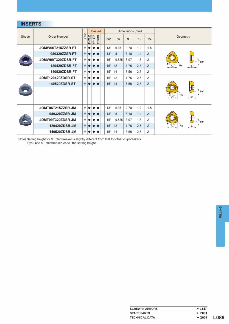
L089
Shape Order Number
Cla
ss
Coated Dimensions (mm)
Geometry
FH70
20VP
15TF
VP30
RT
B3° D1 S1 F1 Re
JOMW06T215ZZSR-FT M a a a 13° 6.35 2.78 1.2 1.5
080320ZZSR-FT M a a a 13° 8 3.18 1.4 2
JDMW09T320ZDSR-FT M a a a 15° 9.525 3.97 1.8 2
120420ZDSR-FT M a a a 15° 12 4.76 2.5 2
140520ZDSR-FT M a a a 15° 14 5.56 2.8 2
JDMT120420ZDSR-ST M a a a 15° 12 4.76 2.5 2
140520ZDSR-ST M a a a 15° 14 5.56 2.8 2
JOMT06T215ZZSR-JM M a a a 13° 6.35 2.78 1.2 1.5
080320ZZSR-JM M a a a 13° 8 3.18 1.4 2
JDMT09T320ZDSR-JM M a a a 15° 9.525 3.97 1.8 2
120420ZDSR-JM M a a a 15° 12 4.76 2.5 2
140520ZDSR-JM M a a a 15° 14 5.56 2.8 2
SCREW-IN ARBORS L147 SPARE PARTS P001 TECHNICAL DATA Q001
S1ReD1F1
B3°
ReD1
F1B3°
S1
B3°
S1ReD1F1
MIL
LIN
G
INSERTS
(Note) Setting height for ST chipbreaker is slightly different from that for other chipbreakers. If you use ST chipbreaker, check the setting height.
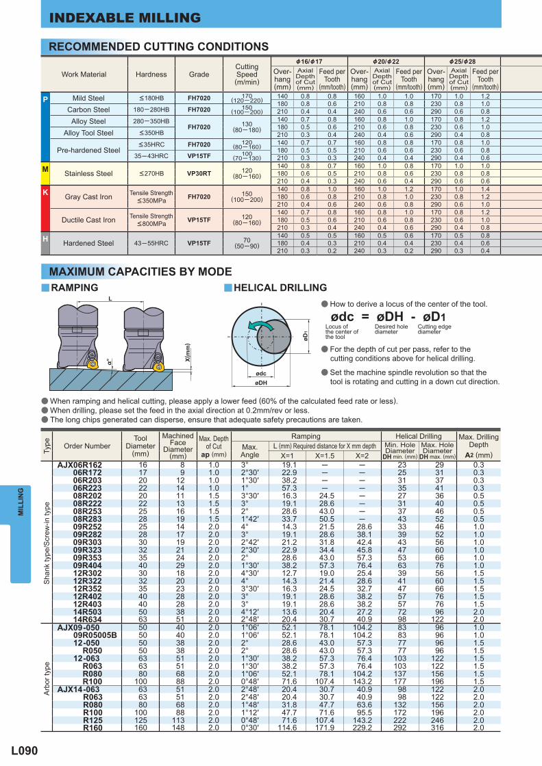
L090
Work Material Hardness Grade Cutting Speed(m/min)
&16/&17 &20/&22 &25/&28 Over-hang(mm)
AxialDepthof Cut(mm)
Feed perTooth
(mm/tooth)
Over-hang(mm)
AxialDepthof Cut(mm)
Feed perTooth
(mm/tooth)
Over-hang(mm)
AxialDepthof Cut(mm)
Feed perTooth
(mm/tooth)
P Mild Steel <180HB FH7020 170(120─220) 140 0.8 0.8 160 1.0 1.0 170 1.0 1.2
180 0.8 0.6 210 0.8 0.8 230 0.8 1.0 Carbon Steel 180─280HB FH7020 150
(100─200) 210 0.4 0.4 240 0.6 0.6 290 0.6 0.8 Alloy Steel 280─350HB
FH7020 130(80─180)
140 0.7 0.8 160 0.8 1.0 170 0.8 1.2180 0.5 0.6 210 0.6 0.8 230 0.6 1.0
Alloy Tool Steel <350HB 210 0.3 0.4 240 0.4 0.6 290 0.4 0.8
Pre-hardened Steel <35HRC FH7020 120
(80─160) 140 0.7 0.7 160 0.8 0.8 170 0.8 1.0180 0.5 0.5 210 0.6 0.6 230 0.6 0.8
35─43HRC VP15TF 100(70─130) 210 0.3 0.3 240 0.4 0.4 290 0.4 0.6
M Stainless Steel <270HB VP30RT 120(80─160)
140 0.8 0.7 160 1.0 0.8 170 1.0 1.0180 0.6 0.5 210 0.8 0.6 230 0.8 0.8210 0.4 0.3 240 0.6 0.4 290 0.6 0.6
K Gray Cast Iron Tensile Strength <350MPa FH7020 150
(100─200)140 0.8 1.0 160 1.0 1.2 170 1.0 1.4180 0.6 0.8 210 0.8 1.0 230 0.8 1.2210 0.4 0.6 240 0.6 0.8 290 0.6 1.0
Ductile Cast Iron Tensile Strength <800MPa VP15TF 120
(80─160)140 0.7 0.8 160 0.8 1.0 170 0.8 1.2180 0.5 0.6 210 0.6 0.8 230 0.6 1.0210 0.3 0.4 240 0.4 0.6 290 0.4 0.8
H Hardened Steel 43─55HRC VP15TF 70(50─90)
140 0.5 0.5 160 0.5 0.6 170 0.5 0.8180 0.4 0.3 210 0.4 0.4 230 0.4 0.6210 0.3 0.2 240 0.3 0.2 290 0.3 0.4
Type
Order Number Tool
Diameter(mm)
MachinedFace
Diameter(mm)
Max. Depth
of Cutap (mm)
Ramping Helical Drilling Max. DrillingDepth
A2 (mm) Max. Angle
L (mm) Required distance for X mm depth Min. HoleDiameter
DH min. (mm)
Max. HoleDiameter
DH max. (mm) X=1 X=1.5 X=2
Sha
nk ty
pe/S
crew
-in ty
pe
AJX06R162 16 8 1.0 3° 19.1 ─ ─ 23 29 0.306R172 17 9 1.0 2°30′ 22.9 ─ ─ 25 31 0.306R203 20 12 1.0 1°30′ 38.2 ─ ─ 31 37 0.306R223 22 14 1.0 1° 57.3 ─ ─ 35 41 0.308R202 20 11 1.5 3°30′ 16.3 24.5 ─ 27 36 0.508R222 22 13 1.5 3° 19.1 28.6 ─ 31 40 0.508R253 25 16 1.5 2° 28.6 43.0 ─ 37 46 0.508R283 28 19 1.5 1°42′ 33.7 50.5 ─ 43 52 0.509R252 25 14 2.0 4° 14.3 21.5 28.6 33 46 1.009R282 28 17 2.0 3° 19.1 28.6 38.1 39 52 1.009R303 30 19 2.0 2°42′ 21.2 31.8 42.4 43 56 1.009R323 32 21 2.0 2°30′ 22.9 34.4 45.8 47 60 1.009R353 35 24 2.0 2° 28.6 43.0 57.3 53 66 1.009R404 40 29 2.0 1°30′ 38.2 57.3 76.4 63 76 1.012R302 30 18 2.0 4°30′ 12.7 19.0 25.4 39 56 1.512R322 32 20 2.0 4° 14.3 21.4 28.6 41 60 1.512R352 35 23 2.0 3°30′ 16.3 24.5 32.7 47 66 1.512R402 40 28 2.0 3° 19.1 28.6 38.2 57 76 1.512R403 40 28 2.0 3° 19.1 28.6 38.2 57 76 1.514R503 50 38 2.0 4°12′ 13.6 20.4 27.2 72 96 2.014R634 63 51 2.0 2°48′ 20.4 30.7 40.9 98 122 2.0
Arb
or ty
pe
AJX09-050 50 40 2.0 1°06′ 52.1 78.1 104.2 83 96 1.009R05005B 50 40 2.0 1°06′ 52.1 78.1 104.2 83 96 1.012-050 50 38 2.0 2° 28.6 43.0 57.3 77 96 1.5
R050 50 38 2.0 2° 28.6 43.0 57.3 77 96 1.512-063 63 51 2.0 1°30′ 38.2 57.3 76.4 103 122 1.5
R063 63 51 2.0 1°30′ 38.2 57.3 76.4 103 122 1.5R080 80 68 2.0 1°06′ 52.1 78.1 104.2 137 156 1.5R100 100 88 2.0 0°48′ 71.6 107.4 143.2 177 196 1.5
AJX14-063 63 51 2.0 2°48′ 20.4 30.7 40.9 98 122 2.0R063 63 51 2.0 2°48′ 20.4 30.7 40.9 98 122 2.0R080 80 68 2.0 1°48′ 31.8 47.7 63.6 132 156 2.0R100 100 88 2.0 1°12′ 47.7 71.6 95.5 172 196 2.0R125 125 113 2.0 0°48′ 71.6 107.4 143.2 222 246 2.0R160 160 148 2.0 0°30′ 114.6 171.9 229.2 292 316 2.0
y y
%°
L
øDHødc
øD1
MIL
LIN
GINDEXABLE MILLING
RECOMMENDED CUTTING CONDITIONS
a How to derive a locus of the center of the tool.
a For the depth of cut per pass, refer to the cutting conditions above for helical drilling.
a Set the machine spindle revolution so that the tool is rotating and cutting in a down cut direction.
ødc = øDH - øD1Locus of the center of the tool
Desired hole diameter
Cutting edge diameter
a When ramping and helical cutting, please apply a lower feed (60% of the calculated feed rate or less).a When drilling, please set the feed in the axial direction at 0.2mm/rev or less.a The long chips generated can disperse, ensure that adequate safety precautions are taken.
X(m
m)
MAXIMUM CAPACITIES BY MODERAMPING HELICAL DRILLING
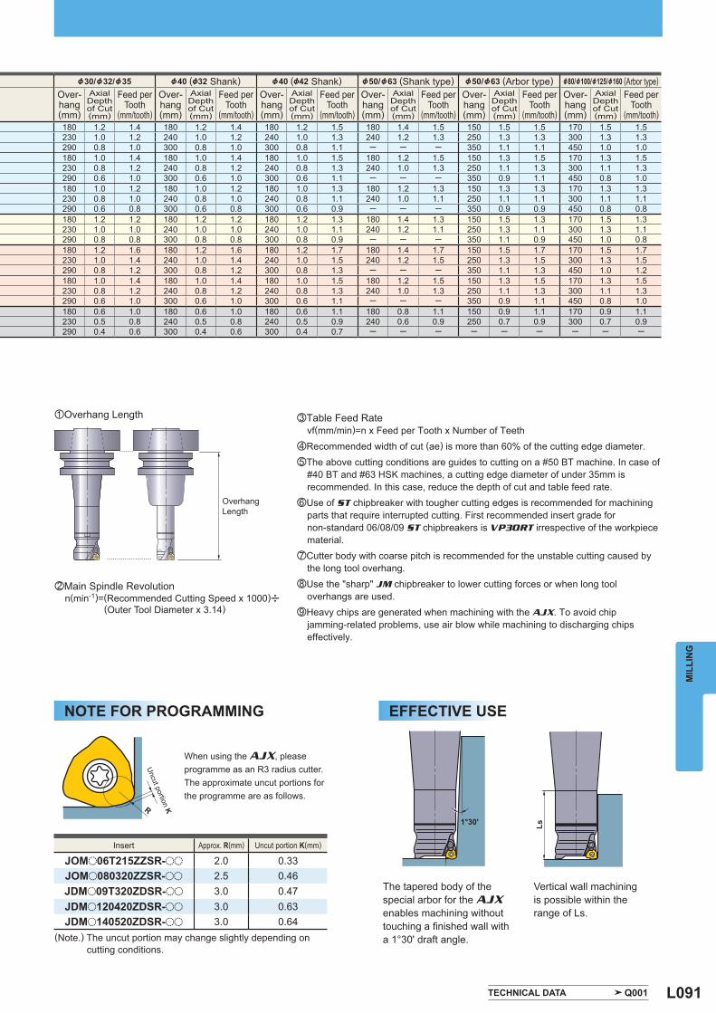
L091
&30/&32/&35 &40 (&32 Shank) &40 (&42 Shank) &50/&63 (Shank type) &50/&63 (Arbor type) &80/&100/&125/&160 (Arbor type) Over-hang(mm)
AxialDepthof Cut(mm)
Feed perTooth
(mm/tooth)
Over-hang(mm)
AxialDepthof Cut(mm)
Feed perTooth
(mm/tooth)
Over-hang(mm)
AxialDepthof Cut(mm)
Feed perTooth
(mm/tooth)
Over-hang(mm)
AxialDepthof Cut(mm)
Feed perTooth
(mm/tooth)
Over-hang(mm)
AxialDepthof Cut(mm)
Feed perTooth
(mm/tooth)
Over-hang(mm)
AxialDepthof Cut(mm)
Feed perTooth
(mm/tooth) 180 1.2 1.4 180 1.2 1.4 180 1.2 1.5 180 1.4 1.5 150 1.5 1.5 170 1.5 1.5230 1.0 1.2 240 1.0 1.2 240 1.0 1.3 240 1.2 1.3 250 1.3 1.3 300 1.3 1.3290 0.8 1.0 300 0.8 1.0 300 0.8 1.1 ─ ─ ─ 350 1.1 1.1 450 1.0 1.0180 1.0 1.4 180 1.0 1.4 180 1.0 1.5 180 1.2 1.5 150 1.3 1.5 170 1.3 1.5230 0.8 1.2 240 0.8 1.2 240 0.8 1.3 240 1.0 1.3 250 1.1 1.3 300 1.1 1.3290 0.6 1.0 300 0.6 1.0 300 0.6 1.1 ─ ─ ─ 350 0.9 1.1 450 0.8 1.0180 1.0 1.2 180 1.0 1.2 180 1.0 1.3 180 1.2 1.3 150 1.3 1.3 170 1.3 1.3230 0.8 1.0 240 0.8 1.0 240 0.8 1.1 240 1.0 1.1 250 1.1 1.1 300 1.1 1.1290 0.6 0.8 300 0.6 0.8 300 0.6 0.9 ─ ─ ─ 350 0.9 0.9 450 0.8 0.8180 1.2 1.2 180 1.2 1.2 180 1.2 1.3 180 1.4 1.3 150 1.5 1.3 170 1.5 1.3230 1.0 1.0 240 1.0 1.0 240 1.0 1.1 240 1.2 1.1 250 1.3 1.1 300 1.3 1.1290 0.8 0.8 300 0.8 0.8 300 0.8 0.9 ─ ─ ─ 350 1.1 0.9 450 1.0 0.8180 1.2 1.6 180 1.2 1.6 180 1.2 1.7 180 1.4 1.7 150 1.5 1.7 170 1.5 1.7230 1.0 1.4 240 1.0 1.4 240 1.0 1.5 240 1.2 1.5 250 1.3 1.5 300 1.3 1.5290 0.8 1.2 300 0.8 1.2 300 0.8 1.3 ─ ─ ─ 350 1.1 1.3 450 1.0 1.2180 1.0 1.4 180 1.0 1.4 180 1.0 1.5 180 1.2 1.5 150 1.3 1.5 170 1.3 1.5230 0.8 1.2 240 0.8 1.2 240 0.8 1.3 240 1.0 1.3 250 1.1 1.3 300 1.1 1.3290 0.6 1.0 300 0.6 1.0 300 0.6 1.1 ─ ─ ─ 350 0.9 1.1 450 0.8 1.0180 0.6 1.0 180 0.6 1.0 180 0.6 1.1 180 0.8 1.1 150 0.9 1.1 170 0.9 1.1230 0.5 0.8 240 0.5 0.8 240 0.5 0.9 240 0.6 0.9 250 0.7 0.9 300 0.7 0.9290 0.4 0.6 300 0.4 0.6 300 0.4 0.7 ─ ─ ─ ─ ─ ─ ─ ─ ─
Insert Approx. R(mm) Uncut portion K(mm)
JOMo06T215ZZSR-oo 2.0 0.33JOMo080320ZZSR-oo 2.5 0.46JDMo09T320ZDSR-oo 3.0 0.47JDMo120420ZDSR-oo 3.0 0.63JDMo140520ZDSR-oo 3.0 0.64
TECHNICAL DATA Q001
1°30' Ls
R
MIL
LIN
G
Overhang Length
xMain Spindle Revolution n(min-1)=(Recommended Cutting Speed x 1000)u (Outer Tool Diameter x 3.14)
cTable Feed Rate vf(mm/min)=n x Feed per Tooth x Number of TeethvRecommended width of cut (ae) is more than 60% of the cutting edge diameter.bThe above cutting conditions are guides to cutting on a #50 BT machine. In case of
#40 BT and #63 HSK machines, a cutting edge diameter of under 35mm is recommended. In this case, reduce the depth of cut and table feed rate.
nUse of ST chipbreaker with tougher cutting edges is recommended for machining parts that require interrupted cutting. First recommended insert grade for non-standard 06/08/09 ST chipbreakers is VP30RT irrespective of the workpiece material.
mCutter body with coarse pitch is recommended for the unstable cutting caused by the long tool overhang.
,Use the "sharp" JM chipbreaker to lower cutting forces or when long tool overhangs are used.
.Heavy chips are generated when machining with the AJX. To avoid chip jamming-related problems, use air blow while machining to discharging chips effectively.
zOverhang Length
When using the AJX, please programme as an R3 radius cutter.The approximate uncut portions for the programme are as follows.
The tapered body of the special arbor for the AJX enables machining without touching a fi nished wall with a 1°30' draft angle.
Vertical wall machining is possible within the range of Ls.
(Note.) The uncut portion may change slightly depending on cutting conditions.
NOTE FOR PROGRAMMING EFFECTIVE USE
Uncut portion K
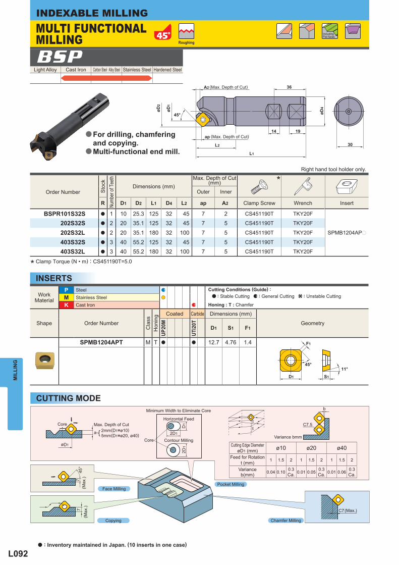
L092
30
øD4
14 19
L1
L2
ap
45°
øD2
øD1
A2 36
F1
45°
D1 S1
11°
tt
7 C7
745
°
øD1
a1
D1
2D1
2D1
C7.5
b
Light Alloy Cast Iron Carbon Steel · Alloy Steel Stainless Steel Hardened Steel BSP
WorkMaterial
P Steel M Stainless Steel K Cast Iron
Shape Order Number
Cla
ss
Hon
ing
Coated Carbide Dimensions (mm)
Geometry
UP20
M
UTi2
0T
D1 S1 F1
SPMB1204APT M T a a 12.7 4.76 1.4
Cutting Edge Diameter øD1 (mm) ø10 ø20 ø40
Feed for Rotation t (mm) 1 1.5 2 1 1.5 2 1 1.5 2
Varianceb(mm) 0.04 0.10 0.3
Ca. 0.01 0.05 0.3 Ca. 0.01 0.06 0.3
Ca.
Order Number
Sto
ck
Numb
er of
Tee
th
Dimensions (mm) Max. Depth of Cut
(mm) * Outer Inner
R D1 D2 L1 D4 L2 ap A2 Clamp Screw Wrench Insert
BSPR101S32S a 1 10 25.3 125 32 45 7 2 CS451190T TKY20F
SPMB1204APp
202S32S a 2 20 35.1 125 32 45 7 5 CS451190T TKY20F
202S32L a 2 20 35.1 180 32 100 7 5 CS451190T TKY20F
403S32S a 3 40 55.2 125 32 45 7 5 CS451190T TKY20F
403S32L a 3 40 55.2 180 32 100 7 5 CS451190T TKY20F
MIL
LIN
GINDEXABLE MILLING
INSERTS* Clamp Torque (N • m) : CS451190T=5.0
Face Milling
Core
(Max
.)
Max. Depth of Cut2mm(D1=ø10)5mm(D1=ø20, ø40)
Copying
Pocket Milling
Chamfer Milling
Minimum Width to Eliminate Core
Horizontal Feed
Contour MillingVariance bmm
Including Flat faces
CUTTING MODE
Roughing
MULTI FUNCTIONAL MILLING
(Max. Depth of Cut)
(Max. Depth of Cut)
Right hand tool holder only.
For drilling, chamfering and copying.Multi-functional end mill.
a
a
Cutting Conditions (Guide) : : Stable Cutting : General Cutting : Unstable Cutting
Honing : T : Chamfer
Core
(Max
.)
(Max.)
a : Inventory maintained in Japan. (10 inserts in one case)
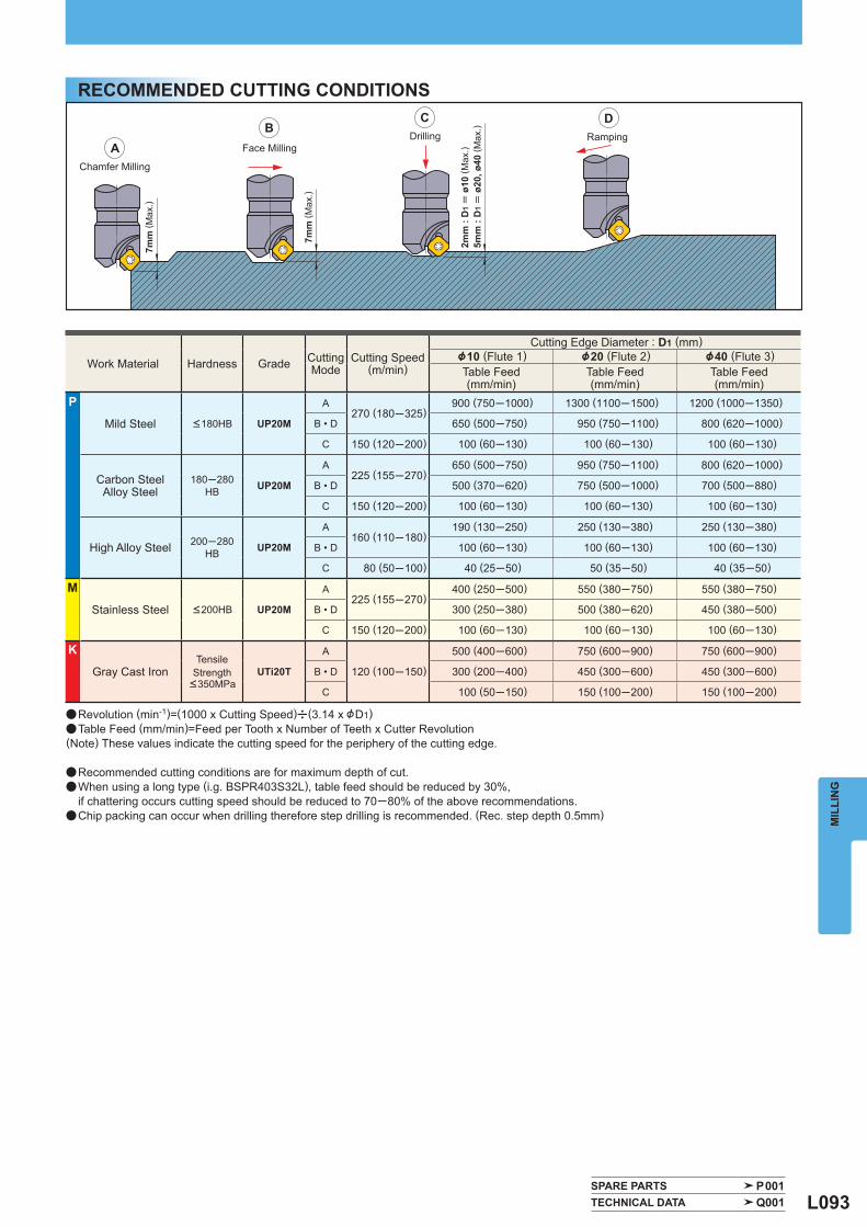
L093
AB
C D
Work Material Hardness Grade CuttingMode
Cutting Speed(m/min)
Cutting Edge Diameter : D1 (mm) &10 (Flute 1) &20 (Flute 2) &40 (Flute 3) Table Feed (mm/min)
Table Feed (mm/min)
Table Feed (mm/min)
P
Mild Steel <180HB UP20M
A270 (180─325)
900 (750─1000) 1300 (1100─1500) 1200 (1000─1350)
B • D 650 (500─750) 950 (750─1100) 800 (620─1000)
C 150 (120─200) 100 (60─130) 100 (60─130) 100 (60─130)
Carbon SteelAlloy Steel
180─280HB UP20M
A225 (155─270)
650 (500─750) 950 (750─1100) 800 (620─1000)
B • D 500 (370─620) 750 (500─1000) 700 (500─880)
C 150 (120─200) 100 (60─130) 100 (60─130) 100 (60─130)
High Alloy Steel 200─280HB UP20M
A160 (110─180)
190 (130─250) 250 (130─380) 250 (130─380)
B • D 100 (60─130) 100 (60─130) 100 (60─130)
C 80 (50─100) 40 (25─50) 50 (35─50) 40 (35─50)
M
Stainless Steel <200HB UP20M
A225 (155─270)
400 (250─500) 550 (380─750) 550 (380─750)
B • D 300 (250─380) 500 (380─620) 450 (380─500)
C 150 (120─200) 100 (60─130) 100 (60─130) 100 (60─130)
K
Gray Cast Iron Tensile
Strength <350MPa
UTi20T
A
120 (100─150)
500 (400─600) 750 (600─900) 750 (600─900)
B • D 300 (200─400) 450 (300─600) 450 (300─600)
C 100 (50─150) 150 (100─200) 150 (100─200)
SPARE PARTS P001 TECHNICAL DATA Q001
MIL
LIN
G
RECOMMENDED CUTTING CONDITIONS
a Revolution (min-1)=(1000 x Cutting Speed)u(3.14 x &D1)a Table Feed (mm/min)=Feed per Tooth x Number of Teeth x Cutter Revolution(Note) These values indicate the cutting speed for the periphery of the cutting edge.
a Recommended cutting conditions are for maximum depth of cut.a When using a long type (i.g. BSPR403S32L), table feed should be reduced by 30%, if chattering occurs cutting speed should be reduced to 70─80% of the above recommendations.a Chip packing can occur when drilling therefore step drilling is recommended. (Rec. step depth 0.5mm)
Chamfer Milling
7mm
( Max
.)Face Milling
Drilling Ramping
7mm
( Max
.)
2mm
: D
1 =
ø10
( Max
.)5m
m :
D1 =
ø20
, ø40
( Max
.)
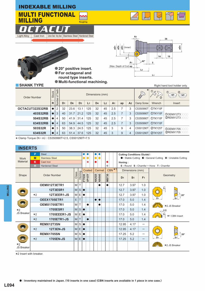
L094
øD4
1914
36
42° 5A1
L1
L2
3°
A2
øD3
øD6
øD1
ap
D1
20°S1
F1F1
D1 S1
20°
2.5
Light Alloy Cast Iron Carbon Steel · Alloy Steel Stainless Steel Hardened Steel OCTACUT
Order Number
Sto
ck
Numb
er of
Tee
th
Dimensions (mm) *
x
z xz
R D1 D6 D3 L1 D4 L2 A1 ap A2 Clamp Screw Wrench Insert
OCTACUT322S32RB a 2 32 23.6 13.1 125 32 45 2.5 7 3 CS350990T zTKY10F
zOEMX12T3pppp
xREMX12T3pppp
403S32RB a 3 40 31.7 21.2 125 32 45 2.5 7 3 CS350990T zTKY10F
504S32RB a 4 50 41.9 31.4 125 32 45 2.5 7 3 CS350990T zTKY10F
634S32RB a 4 63 54.9 44.5 125 32 45 2.5 7 3 CS350990T zTKY10F
503S32R a 3 50 38.3 24.5 125 32 45 3 9 4 CS501290T xTKY25T zOEMX1705pppp
xREMX1705pppp634S32R a 4 63 51.4 37.6 125 32 45 3 9 4 CS501290T xTKY25T
WorkMaterial
P Steel M Stainless Steel
K Cast Iron H Hardened Steel
Shape Order Number
Cla
ss
Hon
ing
Coated Cermet CBN* 1 Dimensions (mm)
Geometry
F703
0VP
15TF
NX25
25NX
4545
MB7
30
D1 S1 F1
OEMX12T3ETR1 M T a a 12.7 3.97 1.012T3ESR1 M S a 12.7 3.97 1.0
* 2 12T3EER1-JS M E a 12.7 3.97 1.0
OEEX1705ETR1 E T a a 17.0 5.0 1.4
OEMX1705ETR1 M T a a 17.0 5.0 1.4
1705ESR1 M S a 17.0 5.0 1.4
* 2 1705EEER1-JS M E a 17.0 5.0 1.4
* 2 1705ETR1-JS M T a 17.0 5.0 1.4
REMX12T3SN M S a 12.95 4.17 ─
* 2 12T3EN-JS M E a 12.95 4.17 ─
REMX1705SN M S a 17.25 5.2 ─
* 2 1705EN-JS M E a 17.25 5.2 ─
y
MIL
LIN
GINDEXABLE MILLING
INSERTS
* Clamp Torque (N • m) : CS350990T=2.5, CS501290T=7.5
*2 Insert with breaker.
*2 JS Breaker
*1 CBN Insert
*2 JS Breaker
(Inner)
Roughing
SHANK TYPE
MULTI FUNCTIONAL MILLING
(Max. Depth of Cut)
Right hand tool holder only.
20° positive insert.For octagonal andround type inserts.Multi-functional machining.
a
a
a
*2JS Breaker
*2JS Breaker
Cutting Conditions (Guide) : : Stable Cutting : General Cutting : Unstable Cutting
Honing : E : Round S : Chamfer + Hone T : Chamfer
a : Inventory maintained in Japan. (10 inserts in one case) (CBN inserts are available in 1 piece in one case.)
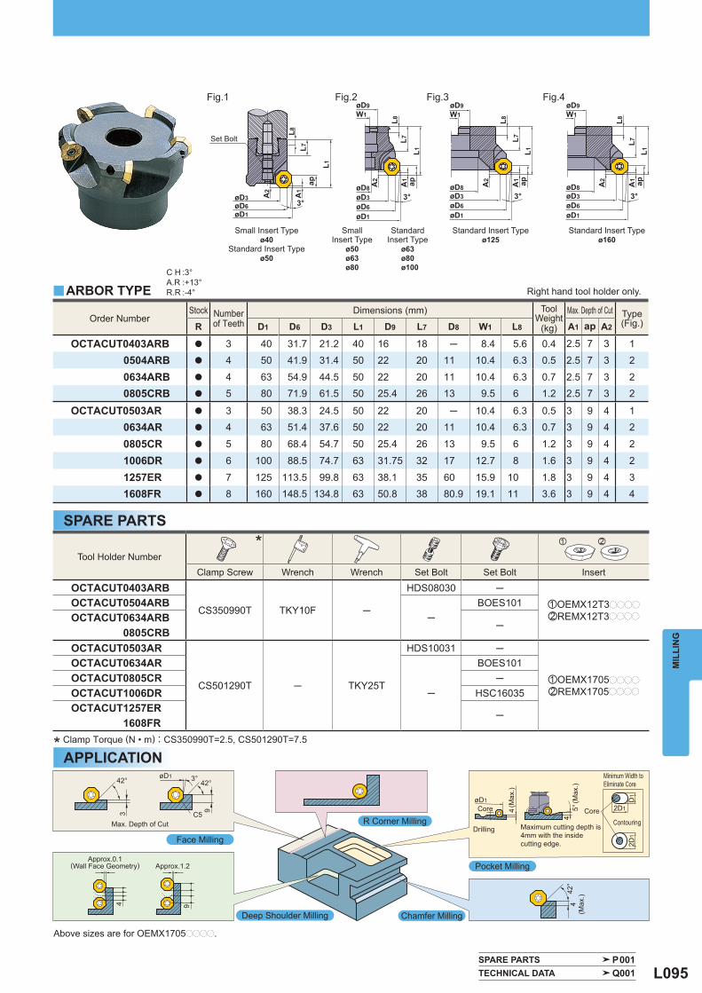
L095
øD1øD6øD3 A
2
A1
3°
ap
L1
L8L7
øD9W1
L8L7
L1
3°
A1 apA2
øD8øD3øD6øD1
øD9W1
L8L7
L1A
1
A2 ap
3°øD8øD3øD6øD1
øD9W1
L8L7
L1
A1
A2 ap
3°øD8øD3øD6øD1
42°
42°3°
C5
42°øD1
3 9
94
øD12D1
2D1
D1
44
4 5°
Order Number Stock Number
of Teeth Dimensions (mm) Tool
Weight (kg)
Max. Depth of Cut Type(Fig.) R D1 D6 D3 L1 D9 L7 D8 W1 L8 A1 ap A2
OCTACUT0403ARB a 3 40 31.7 21.2 40 16 18 ─ 8.4 5.6 0.4 2.5 7 3 10504ARB a 4 50 41.9 31.4 50 22 20 11 10.4 6.3 0.5 2.5 7 3 2
0634ARB a 4 63 54.9 44.5 50 22 20 11 10.4 6.3 0.7 2.5 7 3 20805CRB a 5 80 71.9 61.5 50 25.4 26 13 9.5 6 1.2 2.5 7 3 2
OCTACUT0503AR a 3 50 38.3 24.5 50 22 20 ─ 10.4 6.3 0.5 3 9 4 10634AR a 4 63 51.4 37.6 50 22 20 11 10.4 6.3 0.7 3 9 4 2
0805CR a 5 80 68.4 54.7 50 25.4 26 13 9.5 6 1.2 3 9 4 2
1006DR a 6 100 88.5 74.7 63 31.75 32 17 12.7 8 1.6 3 9 4 2
1257ER a 7 125 113.5 99.8 63 38.1 35 60 15.9 10 1.8 3 9 4 31608FR a 8 160 148.5 134.8 63 50.8 38 80.9 19.1 11 3.6 3 9 4 4
Tool Holder Number * xz
Clamp Screw Wrench Wrench Set Bolt Set Bolt Insert
OCTACUT0403ARB
CS350990T TKY10F ─
HDS08030 ─zOEMX12T3pppp
xREMX12T3pppp
OCTACUT0504ARB─
BOES101OCTACUT0634ARB 0805CRB
─
OCTACUT0503AR
CS501290T ─ TKY25T
HDS10031 ─
zOEMX1705pppp
xREMX1705pppp
OCTACUT0634AR
─
BOES101OCTACUT0805CR ─OCTACUT1006DR HSC16035OCTACUT1257ER 1608FR
─
C H :3°A.R :+13°R.R :-4°y
SPARE PARTS P001 TECHNICAL DATA Q001
MIL
LIN
G
SPARE PARTS
Small Insert Typeø40
Standard Insert Typeø50
SmallInsert Type
ø50ø63ø80
StandardInsert Type
ø63ø80
ø100
Standard Insert Typeø125
Standard Insert Typeø160
* Clamp Torque (N • m) : CS350990T=2.5, CS501290T=7.5
Face Milling
Deep Shoulder Milling
R Corner Milling
Pocket Milling
Chamfer Milling
Above sizes are for OEMX1705pppp.
Set Bolt
Max. Depth of Cut
Approx.1.2Approx.0.1
(Wall Face Geometry)
(Max
.)
(Max
.)
Core Core
Drilling Maximum cutting depth is 4mm with the insidecutting edge.
Minimum Width to Eliminate Core
Contouring
APPLICATION
Fig.1 Fig.2 Fig.3 Fig.4
ARBOR TYPE Right hand tool holder only.
(Max
.)
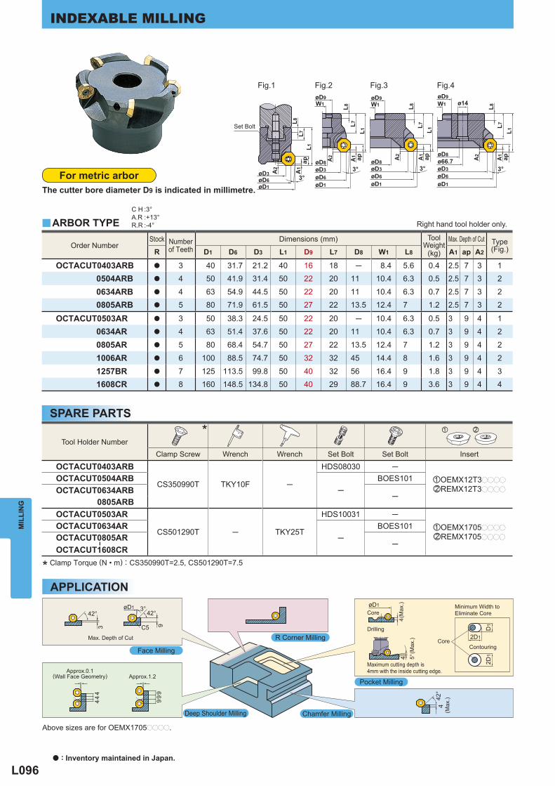
L096
øD1
L7
øD63°øD3
ø66.7øD8
ø14W1øD9 øD9
W1
3°
øD1
L7
øD6øD3øD8
W1
3°øD8
øD1
L7
øD9
øD6øD3
A1A2 A1A2 A1A 2ap ap apL 1
L1L1
L8 L8 L8
øD1øD6øD3 A
2
A1
3°
apL1
L8L7
最大切込み量
0.1程度(壁面形状) 1.2程度
ドリル加工
コア
(最大)
コアを削除できる最小幅
(最大)
コア
(最大)
内刃での切込みは、最大4mm
コンタリング加工
42°
42°3°
C5
42°øD1
3 99
99
444
øD1
2D1
2D1
D1
4
4
4
5°
Order Number Stock Number
of Teeth Dimensions (mm) Tool
Weight (kg)
Max. Depth of Cut Type(Fig.) R D1 D6 D3 L1 D9 L7 D8 W1 L8 A1 ap A2
OCTACUT0403ARB a 3 40 31.7 21.2 40 16 18 ─ 8.4 5.6 0.4 2.5 7 3 10504ARB a 4 50 41.9 31.4 50 22 20 11 10.4 6.3 0.5 2.5 7 3 2
0634ARB a 4 63 54.9 44.5 50 22 20 11 10.4 6.3 0.7 2.5 7 3 20805ARB a 5 80 71.9 61.5 50 27 22 13.5 12.4 7 1.2 2.5 7 3 2
OCTACUT0503AR a 3 50 38.3 24.5 50 22 20 ─ 10.4 6.3 0.5 3 9 4 10634AR a 4 63 51.4 37.6 50 22 20 11 10.4 6.3 0.7 3 9 4 2
0805AR a 5 80 68.4 54.7 50 27 22 13.5 12.4 7 1.2 3 9 4 2
1006AR a 6 100 88.5 74.7 50 32 32 45 14.4 8 1.6 3 9 4 2
1257BR a 7 125 113.5 99.8 50 40 32 56 16.4 9 1.8 3 9 4 31608CR a 8 160 148.5 134.8 50 40 29 88.7 16.4 9 3.6 3 9 4 4
Tool Holder Number * xz
Clamp Screw Wrench Wrench Set Bolt Set Bolt Insert
OCTACUT0403ARB
CS350990T TKY10F ─
HDS08030 ─zOEMX12T3pppp
xREMX12T3pppp
OCTACUT0504ARB─
BOES101OCTACUT0634ARB
─ 0805ARBOCTACUT0503AR
CS501290T ─ TKY25T
HDS10031 ─zOEMX1705pppp
xREMX1705pppp
OCTACUT0634AR─
BOES101OCTACUT0805AR
―
OCTACUT1608CR─
C H :3°A.R :+13°R.R :-4°y
MIL
LIN
GINDEXABLE MILLING
SPARE PARTS
* Clamp Torque (N • m) : CS350990T=2.5, CS501290T=7.5
Core
Drilling
Maximum cutting depth is 4mm with the inside cutting edge.
Minimum Width to Eliminate Core
Contouring
APPLICATION
Fig.1 Fig.2 Fig.3 Fig.4
For metric arborThe cutter bore diameter D9 is indicated in millimetre.
ARBOR TYPE Right hand tool holder only.
Above sizes are for OEMX1705pppp.
Max. Depth of Cut
Approx.1.2Approx.0.1
(Wall Face Geometry)
Face Milling
Deep Shoulder Milling
R Corner Milling
Chamfer Milling
Pocket Milling
(Max
.)
(Max
.)
(Max
.)
Core
a : Inventory maintained in Japan.
Set Bolt
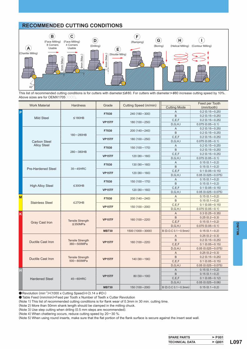
L097
A
B CD
E
FG H I
42°
Work Material Hardness Grade Cutting Speed (m/min) Feed per Tooth Cutting Mode (mm/tooth)
P Mild Steel <180HB
F7030 240 (180─300) A 0.2 (0.15─0.25)B 0.2 (0.15─0.25)
VP15TF 180 (100─250) C,E,F 0.2 (0.15─0.25)D,G,H,I 0.075 (0.05─0.1)
Carbon SteelAlloy Steel
180─280HB F7030 200 (140─240) A 0.2 (0.15─0.25)
B 0.2 (0.15─0.25)
VP15TF 180 (100─250) C,E,F 0.2 (0.15─0.25)D,G,H,I 0.075 (0.05─0.1)
280─380HB F7030 150 (100─170) A 0.2 (0.15─0.25)
B 0.2 (0.15─0.25)
VP15TF 120 (80─160) C,E,F 0.2 (0.15─0.25)D,G,H,I 0.075 (0.05─0.1)
Pre-Hardened Steel 35─45HRC F7030 130 (90─160) A 0.15 (0.1─0.2)
B 0.15 (0.1─0.2)
VP15TF 120 (80─160) C,E,F 0.1 (0.05─0.15)D,G,H,I 0.05 (0.025─0.075)
High Alloy Steel <300HB F7030 150 (100─170) A 0.15 (0.1─0.2)
B 0.15 (0.1─0.2)
VP15TF 120 (80─160) C,E,F 0.1 (0.05─0.15)D,G,H,I 0.05 (0.025─0.075)
M Stainless Steel <270HB
F7030 200 (140─240) A 0.15 (0.1─0.2)B 0.15 (0.1─0.2)
VP15TF 150 (100─200) C,E,F 0.1 (0.05─0.15)D,G,H,I 0.075 (0.05─0.1)
K
Gray Cast Iron Tensile Strength <350MPa
VP15TF 160 (100─220)
A 0.3 (0.25─0.35)B 0.25 (0.2─0.3)
C,E,F 0.15 (0.1─0.2)D,G,H,I 0.075 (0.05─0.1)
MB730 1500 (1000─3000) B (D.O.C 0.1─0.5mm) 0.15 (0.1─0.2)
Ductile Cast Iron Tensile Strength 360─500MPa VP15TF 160 (100─220)
A 0.25 (0.2─0.3)B 0.2 (0.15─0.25)
C,E,F 0.1 (0.05─0.15)D,G,H,I 0.05 (0.025─0.075)
Ductile Cast Iron Tensile Strength 500─800MPa VP15TF 140 (90─190)
A 0.25 (0.2─0.3)B 0.2 (0.15─0.25)
C,E,F 0.1 (0.05─0.15)D,G,H,I 0.05 (0.025─0.075)
H
Hardened Steel 45─60HRC VP15TF 80 (50─100)
A 0.15 (0.1─0.2)B 0.15 (0.1─0.2)
C,E,F 0.1 (0.05─0.12)D,G,H,I 0.05 (0.025─0.06)
MB730 150 (100─200) B (D.O.C 0.1─0.3mm) 0.15 (0.1─0.2)
SPARE PARTS P001 TECHNICAL DATA Q001
MIL
LIN
G
RECOMMENDED CUTTING CONDITIONS
This list of recommended cutting conditions is for cutters with diameter<&80. For cutters with diameter>&80 increase cutting speed by 10%. Above sizes are for OEMX1705pppp.
(Chamfer Milling)
(Face Milling)8 Corners
Usable
(Face Milling)4 Corners
Usable(Drilling)
(Shoulder Milling)
(Ramping)(Boring) (Helical Milling) (Contour Milling)
a Revolution (min-1)=(1000 x Cutting Speed)u(3.14 x &D1)a Table Feed (mm/min)=Feed per Tooth x Number of Teeth x Cutter Revolution(Note 1) This list of recommended cutting conditions is for fl ank wear of 0.3mm in 30 min. cutting time.(Note 2) More than 50mm shank length should be clamped in the milling chuck.(Note 3) Use step cutting when driling (0.5 mm steps are recommended).(Note 4) When chattering occurs, reduce cutting speed by 20─30 %.(Note 5) When using round inserts, make sure that the fl at portion of the fl ank surface is secure against the insert seat wall.
3mm
( Max
.)
9mm
( Max
.)
4mm
( Max
.)
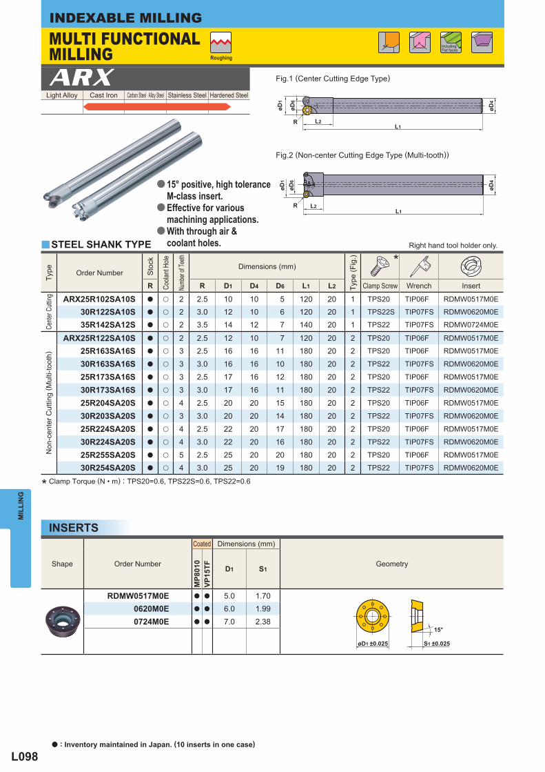
L098
R
L1L2R
R
øD1
øD6
øD4
øD4
L1L2
øD6
øD1
øD1 ±0.025 S1 ±0.025
15°
Light Alloy Cast Iron Carbon Steel · Alloy Steel Stainless Steel Hardened Steel ARX
Type
Order Number
Sto
ck
Coola
nt H
ole
Numb
er of
Teeth
Dimensions (mm)
Type
(Fig
.)
*
R R D1 D4 D6 L1 L2 Clamp Screw Wrench Insert
Cente
r Cutt
ing
ARX25R102SA10S a u 2 2.5 10 10 5 120 20 1 TPS20 TIP06F RDMW0517M0E
30R122SA10S a u 2 3.0 12 10 6 120 20 1 TPS22S TIP07FS RDMW0620M0E
35R142SA12S a u 2 3.5 14 12 7 140 20 1 TPS22 TIP07FS RDMW0724M0E
Non
-cen
ter C
uttin
g ( M
ulti-
toot
h)
ARX25R122SA10S a u 2 2.5 12 10 7 120 20 2 TPS20 TIP06F RDMW0517M0E
25R163SA16S a u 3 2.5 16 16 11 180 20 2 TPS20 TIP06F RDMW0517M0E
30R163SA16S a u 3 3.0 16 16 10 180 20 2 TPS22 TIP07FS RDMW0620M0E
25R173SA16S a u 3 2.5 17 16 12 180 20 2 TPS20 TIP06F RDMW0517M0E
30R173SA16S a u 3 3.0 17 16 11 180 20 2 TPS22 TIP07FS RDMW0620M0E
25R204SA20S a u 4 2.5 20 20 15 180 20 2 TPS20 TIP06F RDMW0517M0E
30R203SA20S a u 3 3.0 20 20 14 180 20 2 TPS22 TIP07FS RDMW0620M0E
25R224SA20S a u 4 2.5 22 20 17 180 20 2 TPS20 TIP06F RDMW0517M0E
30R224SA20S a u 4 3.0 22 20 16 180 20 2 TPS22 TIP07FS RDMW0620M0E
25R255SA20S a u 5 2.5 25 20 20 180 20 2 TPS20 TIP06F RDMW0517M0E
30R254SA20S a u 4 3.0 25 20 19 180 20 2 TPS22 TIP07FS RDMW0620M0E
Shape Order Number
Coated Dimensions (mm)
Geometry
MP8
010
VP15
TF D1 S1
RDMW0517M0E a a 5.0 1.700620M0E a a 6.0 1.99
0724M0E a a 7.0 2.38
y
MIL
LIN
GINDEXABLE MILLING
INSERTS
* Clamp Torque (N • m) : TPS20=0.6, TPS22S=0.6, TPS22=0.6
Fig.1 (Center Cutting Edge Type)
Fig.2 (Non-center Cutting Edge Type (Multi-tooth))
Including Flat faces
Roughing
MULTI FUNCTIONAL MILLING
Right hand tool holder only.
15° positive, high toleranceM-class insert.Effective for variousmachining applications.With through air &coolant holes.
a
a
a
STEEL SHANK TYPE
a : Inventory maintained in Japan. (10 inserts in one case)
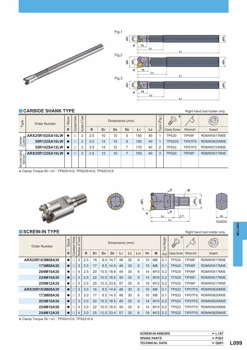
L099
R
øD4
øD4
øD4
L1L2
15
R
L1
15
R
L1
15L2
L2
øD6
øD1
øD6
øD1
øD6
øD1
øD4
øD5
M
RL2
L1
L11
A
A
øD1
H1
Type
Order Number
Sto
ck
Coola
nt H
ole
Numb
er of
Teeth
Dimensions (mm)
Type
(Fig
.)
*
R R D1 D4 D6 L1 L2 Clamp Screw Wrench Insert
Cen
ter
Cut
ting
ARX25R102SA10LW a u 2 2.5 10 10 5 150 40 1 TPS20 TIP06F RDMW0517M0E
30R122SA10LW a u 2 3.0 12 10 6 150 40 1 TPS22S TIP07FS RDMW0620M0E
35R142SA12LW a u 2 3.5 14 12 7 170 40 2 TPS22 TIP07FS RDMW0724M0E
Non-c
enter
Cuttin
g ( M
ulti-to
oth)
ARX25R122SA10LW a u 2 2.5 12 10 7 150 40 3 TPS20 TIP06F RDMW0517M0E
Order Number
Sto
ck
Coo
lant
Hol
e
Numb
er of
Tee
th
Dimensions (mm)
Tool
Weig
ht
(kg)
*
R R D1 D4 D5 L1 L2 L11 H1 M Clamp Screw Wrench Insert
ARX25R163M08A30 a u 3 2.5 16 8.5 14.7 48 30 6 10 M8 0.1 TPS20 TIP06F RDMW0517M0E
173M08A30 a u 3 2.5 17 8.5 14.5 48 30 6 10 M8 0.1 TPS20 TIP06F RDMW0517M0E
204M10A30 a u 4 2.5 20 10.5 18.6 49 30 6 14 M10 0.2 TPS20 TIP06F RDMW0517M0E
224M10A30 a u 4 2.5 22 10.5 18.5 49 30 6 14 M10 0.2 TPS20 TIP06F RDMW0517M0E
255M12A35 a u 5 2.5 25 12.5 23.6 57 35 6 19 M12 0.2 TPS20 TIP06F RDMW0517M0E
ARX30R163M08A30 a u 3 3.0 16 8.5 14.6 48 30 6 10 M8 0.1 TPS22 TIP07FS RDMW0620M0E
173M08A30 a u 3 3.0 17 8.5 14.5 48 30 6 10 M8 0.1 TPS22 TIP07FS RDMW0620M0E
203M10A30 a u 3 3.0 20 10.5 18.5 49 30 6 14 M10 0.2 TPS22 TIP07FS RDMW0620M0E
224M10A30 a u 4 3.0 22 10.5 18.5 49 30 6 14 M10 0.2 TPS22 TIP07FS RDMW0620M0E
254M12A35 a u 4 3.0 25 12.5 23.4 57 35 6 19 M12 0.2 TPS22 TIP07FS RDMW0620M0E
y
y
SCREW-IN ARBORS L147 SPARE PARTS P001 TECHNICAL DATA Q001
MIL
LIN
G
* Clamp Torque (N • m) : TPS20=0.6, TPS22S=0.6, TPS22=0.6
* Clamp Torque (N • m) : TPS20=0.6, TPS22=0.6
Fig.1
Fig.2
Fig.3
Right hand tool holder only.
Right hand tool holder only.
CARBIDE SHANK TYPE
SCREW-IN TYPE
A-A section
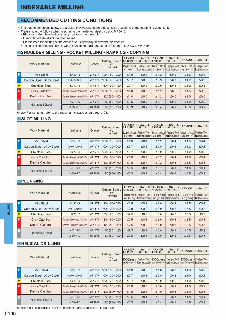
L100
Work Material Hardness Grade Cutting Speed
vc (m/min)
ARX25RpppSAppSARX25RpppMppApp
ARX30RpppSAppSARX30RpppMppApp
ARX35RpppSAppS
Depth of Cut ap (mm)
Feed per Tooth fz (mm/tooth)
Depth of Cut ap (mm)
Feed per Tooth fz (mm/tooth)
Depth of Cut ap (mm)
Feed per Tooth fz (mm/tooth)
P Mild Steel <180HB VP15TF 180 (150─220) <1.0 <0.5 <1.2 <0.5 <1.5 <0.5
Carbon Steel • Alloy Steel 180─350HB VP15TF 160 (120─200) <0.7 <0.3 <0.9 <0.3 <1.2 <0.3
M Stainless Steel <270HB VP15TF 150 (120─180) <0.7 <0.3 <0.9 <0.3 <1.2 <0.3
K Gray Cast Iron Tensile Strength<350MPa VP15TF 180 (150─220) <1.0 <0.5 <1.2 <0.5 <1.5 <0.5
Ductile Cast Iron Tensile Strength<800MPa VP15TF 120 (80─160) <1.0 <0.5 <1.2 <0.5 <1.5 <0.5
H Hardened Steel
<50HRC VP15TF 80 (50─120) <0.5 <0.2 <0.7 <0.2 <1.0 <0.2
>50HRC MP8010 80 (50─120) <0.3 <0.2 <0.4 <0.2 <0.5 <0.2
y
y
y
y
Work Material Hardness Grade Cutting Speed
vc (m/min)
ARX25RpppSAppSARX25RpppMppApp
ARX30RpppSAppSARX30RpppMppApp
ARX35RpppSAppS
Depth of Cut ap (mm)
Feed per Tooth fz (mm/tooth)
Depth of Cut ap (mm)
Feed per Tooth fz (mm/tooth)
Depth of Cut ap (mm)
Feed per Tooth fz (mm/tooth)
P Mild Steel <180HB VP15TF 180 (150─220) <1.0 <0.4 <1.2 <0.4 <1.5 <0.4
Carbon Steel • Alloy Steel 180─350HB VP15TF 160 (120─200) <0.7 <0.2 <0.9 <0.2 <1.2 <0.2
M Stainless Steel <270HB VP15TF 150 (120─180) <0.7 <0.2 <0.9 <0.2 <1.2 <0.2
K Gray Cast Iron Tensile Strength<350MPa VP15TF 180 (150─220) <1.0 <0.4 <1.2 <0.4 <1.5 <0.4
Ductile Cast Iron Tensile Strength<800MPa VP15TF 120 (80─160) <1.0 <0.4 <1.2 <0.4 <1.5 <0.4
H Hardened Steel
<50HRC VP15TF 80 (50─120) <0.5 <0.1 <0.7 <0.1 <1.0 <0.1
>50HRC MP8010 80 (50─120) <0.3 <0.1 <0.4 <0.1 <0.5 <0.1
Work Material Hardness Grade Cutting Speed
vc (m/min)
ARX25RpppSAppSARX25RpppMppApp
ARX30RpppSAppSARX30RpppMppApp
ARX35RpppSAppS
Cutting Width ae (mm)
Feed per Tooth fz (mm/tooth)
Cutting Width ae (mm)
Feed per Tooth fz (mm/tooth)
Cutting Width ae (mm)
Feed per Tooth fz (mm/tooth)
P Mild Steel <180HB VP15TF 180 (150─220) <2.5 <0.3 <3.0 <0.3 <3.5 <0.3
Carbon Steel • Alloy Steel 180─350HB VP15TF 160 (120─200) <2.5 <0.2 <3.0 <0.2 <3.5 <0.2
M Stainless Steel <270HB VP15TF 150 (120─180) <2.5 <0.2 <3.0 <0.2 <3.5 <0.2
K Gray Cast Iron Tensile Strength<350MPa VP15TF 180 (150─220) <2.5 <0.3 <3.0 <0.3 <3.5 <0.3
Ductile Cast Iron Tensile Strength<800MPa VP15TF 120 (80─160) <2.5 <0.3 <3.0 <0.3 <3.5 <0.3
H Hardened Steel
<50HRC VP15TF 80 (50─120) <2.5 <0.1 <3.0 <0.1 <3.5 <0.1
>50HRC MP8010 80 (50─120) <2.5 <0.1 <3.0 <0.1 <3.5 <0.1
Work Material Hardness Grade Cutting Speed
vc (m/min)
ARX25RpppSAppSARX25RpppMppApp
ARX30RpppSAppSARX30RpppMppApp
ARX35RpppSAppS
DOC/passap (mm/pass)
Feed per Tooth fz (mm/tooth)
DOC/passap (mm/pass)
Feed per Tooth fz (mm/tooth)
DOC/passap (mm/pass)
Feed per Tooth fz (mm/tooth)
P Mild Steel <180HB VP15TF 180 (150─220) <1.0 <0.3 <1.0 <0.3 <1.0 <0.3
Carbon Steel • Alloy Steel 180─350HB VP15TF 160 (120─200) <0.7 <0.2 <0.9 <0.2 <1.0 <0.2
M Stainless Steel <270HB VP15TF 150 (120─180) <0.7 <0.2 <0.9 <0.2 <1.0 <0.2
K Gray Cast Iron Tensile Strength<350MPa VP15TF 180 (150─220) <1.0 <0.3 <1.0 <0.3 <1.0 <0.3
Ductile Cast Iron Tensile Strength<800MPa VP15TF 120 (80─160) <1.0 <0.3 <1.0 <0.3 <1.0 <0.3
H Hardened Steel
<50HRC VP15TF 80 (50─120) <0.5 <0.1 <0.7 <0.1 <1.0 <0.1
>50HRC MP8010 80 (50─120) <0.3 <0.1 <0.4 <0.1 <0.5 <0.1
MIL
LIN
GINDEXABLE MILLING
SHOULDER MILLING • POCKET MILLING • RAMPING • COPYING
SLOT MILLING
PLUNGING
HELICAL DRILLING
(Note) For ramping, refer to the maximum capacities on page L101.
(Note) For helical drilling, refer to the maximum capacities on page L101.
RECOMMENDED CUTTING CONDITIONS
* The cutting conditions below are a guide only.Please make adjustments according to the machining conditions.
* Please note the follows when machining the hardened steel by using MP8010. • Please shorten the overhang length as much as possible. • Use with carbide shank recommended. • Please note the setting of the depth of cut especially to prevent the fracture. • The fi rst recommended grade when machining hardened steel of less than 50HRC is VP15TF.
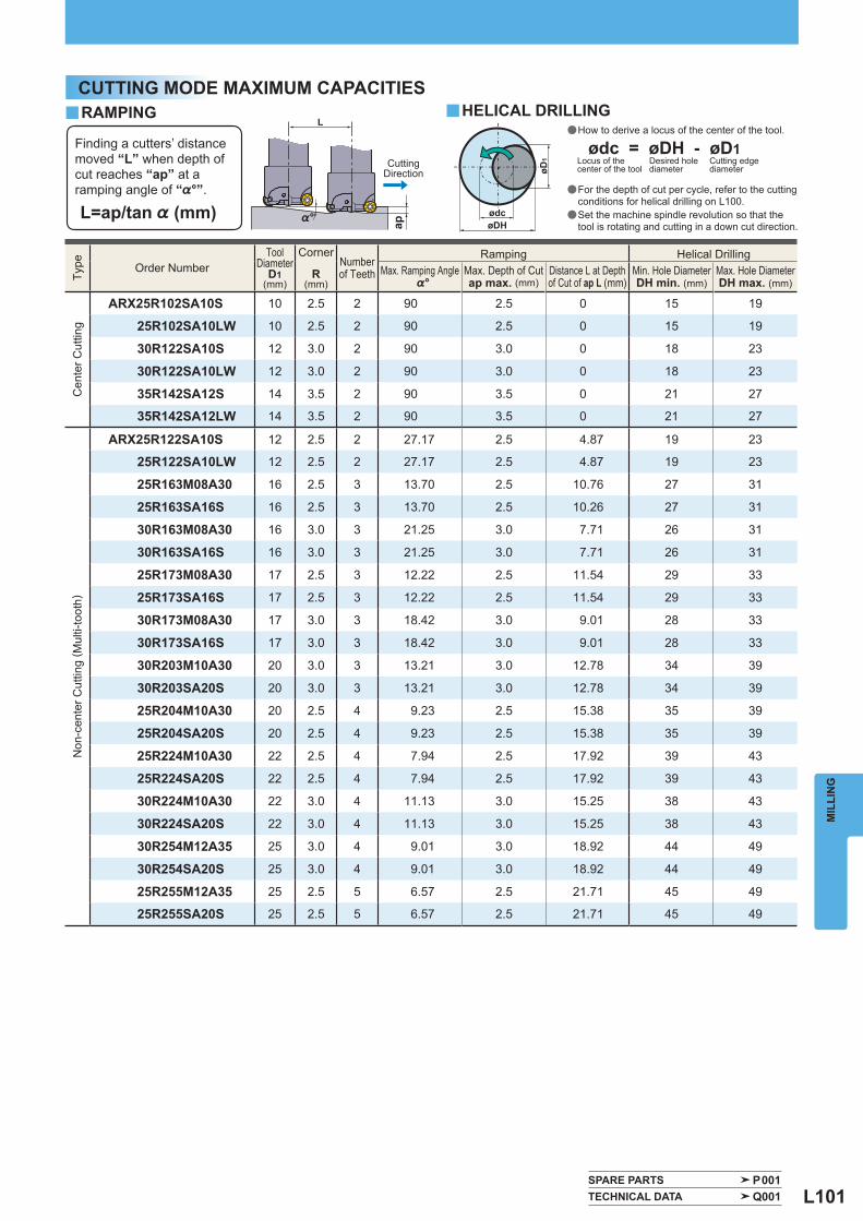
L101
L
ap%°øDHødc
øD1
Type
Order Number
Tool Diameter
D1(mm)
Corner
R(mm)
Number of Teeth
Ramping Helical Drilling Max. Ramping Angle
%° Max. Depth of Cut ap max. (mm)
Distance L at Depthof Cut of ap L (mm)
Min. Hole Diameter DH min. (mm)
Max. Hole Diameter DH max. (mm)
Cen
ter C
uttin
g
ARX25R102SA10S 10 2.5 2 90 2.5 0 15 19
25R102SA10LW 10 2.5 2 90 2.5 0 15 19
30R122SA10S 12 3.0 2 90 3.0 0 18 23
30R122SA10LW 12 3.0 2 90 3.0 0 18 23
35R142SA12S 14 3.5 2 90 3.5 0 21 27
35R142SA12LW 14 3.5 2 90 3.5 0 21 27
Non
-cen
ter C
uttin
g ( M
ulti-
toot
h)
ARX25R122SA10S 12 2.5 2 27.17 2.5 4.87 19 23
25R122SA10LW 12 2.5 2 27.17 2.5 4.87 19 23
25R163M08A30 16 2.5 3 13.70 2.5 10.76 27 31
25R163SA16S 16 2.5 3 13.70 2.5 10.26 27 31
30R163M08A30 16 3.0 3 21.25 3.0 7.71 26 31
30R163SA16S 16 3.0 3 21.25 3.0 7.71 26 31
25R173M08A30 17 2.5 3 12.22 2.5 11.54 29 33
25R173SA16S 17 2.5 3 12.22 2.5 11.54 29 33
30R173M08A30 17 3.0 3 18.42 3.0 9.01 28 33
30R173SA16S 17 3.0 3 18.42 3.0 9.01 28 33
30R203M10A30 20 3.0 3 13.21 3.0 12.78 34 39
30R203SA20S 20 3.0 3 13.21 3.0 12.78 34 39
25R204M10A30 20 2.5 4 9.23 2.5 15.38 35 39
25R204SA20S 20 2.5 4 9.23 2.5 15.38 35 39
25R224M10A30 22 2.5 4 7.94 2.5 17.92 39 43
25R224SA20S 22 2.5 4 7.94 2.5 17.92 39 43
30R224M10A30 22 3.0 4 11.13 3.0 15.25 38 43
30R224SA20S 22 3.0 4 11.13 3.0 15.25 38 43
30R254M12A35 25 3.0 4 9.01 3.0 18.92 44 49
30R254SA20S 25 3.0 4 9.01 3.0 18.92 44 49
25R255M12A35 25 2.5 5 6.57 2.5 21.71 45 49
25R255SA20S 25 2.5 5 6.57 2.5 21.71 45 49
y y
SPARE PARTS P001 TECHNICAL DATA Q001
MIL
LIN
G
RAMPING HELICAL DRILLING
Finding a cutters’ distance moved “L” when depth of cut reaches “ap” at a ramping angle of “%°”.
L=ap/tan % (mm)
CuttingDirection
ødc = øDH - øD1Locus of the center of the tool
Desired hole diameter
Cutting edge diameter
CUTTING MODE MAXIMUM CAPACITIES
a How to derive a locus of the center of the tool.
a For the depth of cut per cycle, refer to the cutting conditions for helical drilling on L100. a Set the machine spindle revolution so that the tool is rotating and cutting in a down cut direction.
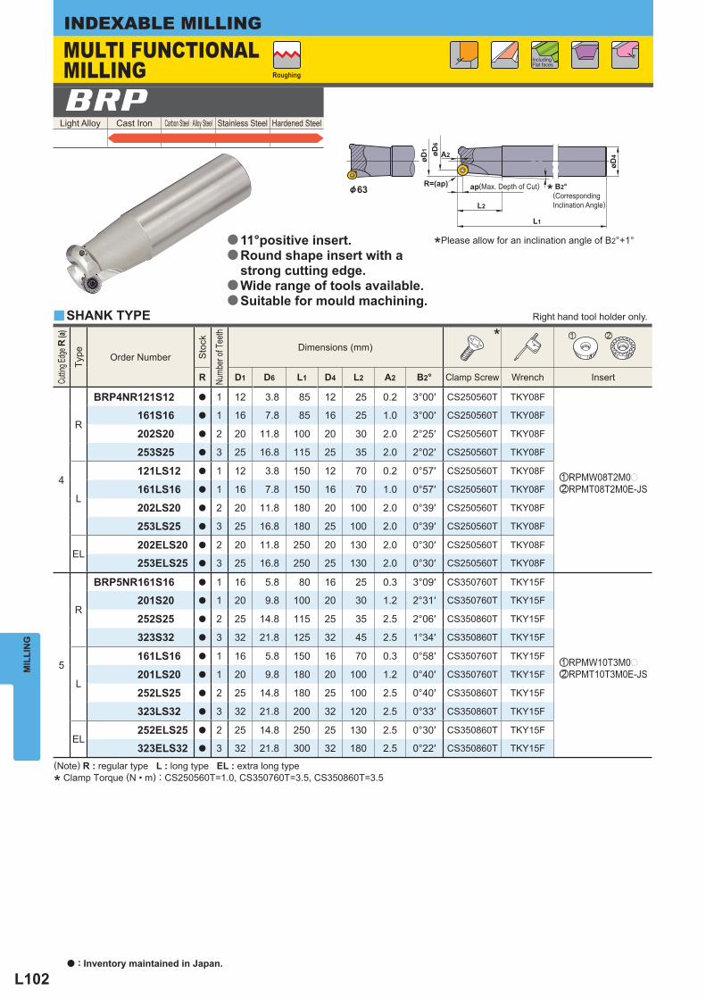
L102
øD6
A2
L2
apR=(ap)
øD4
L1
øD1
Light Alloy Cast Iron Carbon Steel · Alloy Steel Stainless Steel Hardened Steel BRP
Cuttin
g Edg
e R (a
)
Type
Order Number
Sto
ck
Numb
er of
Tee
th
Dimensions (mm) * z x
R D1 D6 L1 D4 L2 A2 B2° Clamp Screw Wrench Insert
4
R
BRP4NR121S12 a 1 12 3.8 85 12 25 0.2 3°00′ CS250560T TKY08F
zRPMW08T2M0pxRPMT08T2M0E-JS
161S16 a 1 16 7.8 85 16 25 1.0 3°00′ CS250560T TKY08F
202S20 a 2 20 11.8 100 20 30 2.0 2°25′ CS250560T TKY08F
253S25 a 3 25 16.8 115 25 35 2.0 2°02′ CS250560T TKY08F
L
121LS12 a 1 12 3.8 150 12 70 0.2 0°57′ CS250560T TKY08F
161LS16 a 1 16 7.8 150 16 70 1.0 0°57′ CS250560T TKY08F
202LS20 a 2 20 11.8 180 20 100 2.0 0°39′ CS250560T TKY08F
253LS25 a 3 25 16.8 180 25 100 2.0 0°39′ CS250560T TKY08F
EL202ELS20 a 2 20 11.8 250 20 130 2.0 0°30′ CS250560T TKY08F
253ELS25 a 3 25 16.8 250 25 130 2.0 0°30′ CS250560T TKY08F
5
R
BRP5NR161S16 a 1 16 5.8 80 16 25 0.3 3°09′ CS350760T TKY15F
zRPMW10T3M0pxRPMT10T3M0E-JS
201S20 a 1 20 9.8 100 20 30 1.2 2°31′ CS350760T TKY15F
252S25 a 2 25 14.8 115 25 35 2.5 2°06′ CS350860T TKY15F
323S32 a 3 32 21.8 125 32 45 2.5 1°34′ CS350860T TKY15F
L
161LS16 a 1 16 5.8 150 16 70 0.3 0°58′ CS350760T TKY15F
201LS20 a 1 20 9.8 180 20 100 1.2 0°40′ CS350760T TKY15F
252LS25 a 2 25 14.8 180 25 100 2.5 0°40′ CS350860T TKY15F
323LS32 a 3 32 21.8 200 32 120 2.5 0°33′ CS350860T TKY15F
EL252ELS25 a 2 25 14.8 250 25 130 2.5 0°30′ CS350860T TKY15F
323ELS32 a 3 32 21.8 300 32 180 2.5 0°22′ CS350860T TKY15F
y
MIL
LIN
GINDEXABLE MILLING
(Note) R : regular type L : long type EL : extra long type
* Clamp Torque (N • m) : CS250560T=1.0, CS350760T=3.5, CS350860T=3.5
&63
Including Flat faces
Roughing
SHANK TYPE
MULTI FUNCTIONAL MILLING
(Max. Depth of Cut)
Right hand tool holder only.
11°positive insert.Round shape insert with a strong cutting edge.Wide range of tools available.Suitable for mould machining.
a
a
a
a
*Please allow for an inclination angle of B2°+1°
* B2°(Corresponding Inclination Angle)
a : Inventory maintained in Japan.
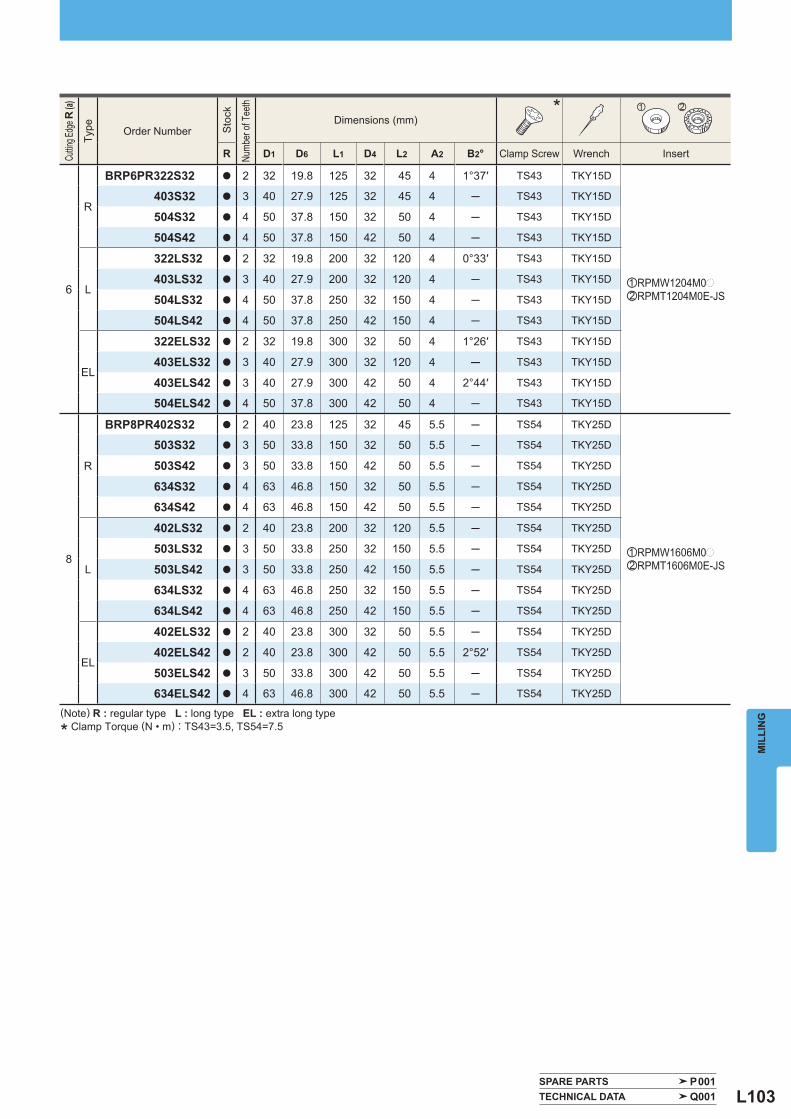
L103
Cuttin
g Edg
e R (a
)
Type
Order Number
Sto
ck
Numb
er of
Tee
th
Dimensions (mm) * z x
R D1 D6 L1 D4 L2 A2 B2° Clamp Screw Wrench Insert
6
R
BRP6PR322S32 a 2 32 19.8 125 32 45 4 1°37′ TS43 TKY15D
zRPMW1204M0pxRPMT1204M0E-JS
403S32 a 3 40 27.9 125 32 45 4 ─ TS43 TKY15D
504S32 a 4 50 37.8 150 32 50 4 ─ TS43 TKY15D
504S42 a 4 50 37.8 150 42 50 4 ─ TS43 TKY15D
L
322LS32 a 2 32 19.8 200 32 120 4 0°33′ TS43 TKY15D
403LS32 a 3 40 27.9 200 32 120 4 ─ TS43 TKY15D
504LS32 a 4 50 37.8 250 32 150 4 ─ TS43 TKY15D
504LS42 a 4 50 37.8 250 42 150 4 ─ TS43 TKY15D
EL
322ELS32 a 2 32 19.8 300 32 50 4 1°26′ TS43 TKY15D
403ELS32 a 3 40 27.9 300 32 120 4 ─ TS43 TKY15D
403ELS42 a 3 40 27.9 300 42 50 4 2°44′ TS43 TKY15D
504ELS42 a 4 50 37.8 300 42 50 4 ─ TS43 TKY15D
8
R
BRP8PR402S32 a 2 40 23.8 125 32 45 5.5 ─ TS54 TKY25D
zRPMW1606M0pxRPMT1606M0E-JS
503S32 a 3 50 33.8 150 32 50 5.5 ─ TS54 TKY25D
503S42 a 3 50 33.8 150 42 50 5.5 ─ TS54 TKY25D
634S32 a 4 63 46.8 150 32 50 5.5 ─ TS54 TKY25D
634S42 a 4 63 46.8 150 42 50 5.5 ─ TS54 TKY25D
L
402LS32 a 2 40 23.8 200 32 120 5.5 ─ TS54 TKY25D
503LS32 a 3 50 33.8 250 32 150 5.5 ─ TS54 TKY25D
503LS42 a 3 50 33.8 250 42 150 5.5 ─ TS54 TKY25D
634LS32 a 4 63 46.8 250 32 150 5.5 ─ TS54 TKY25D
634LS42 a 4 63 46.8 250 42 150 5.5 ─ TS54 TKY25D
EL
402ELS32 a 2 40 23.8 300 32 50 5.5 ─ TS54 TKY25D
402ELS42 a 2 40 23.8 300 42 50 5.5 2°52′ TS54 TKY25D
503ELS42 a 3 50 33.8 300 42 50 5.5 ─ TS54 TKY25D
634ELS42 a 4 63 46.8 300 42 50 5.5 ─ TS54 TKY25D
SPARE PARTS P001 TECHNICAL DATA Q001
MIL
LIN
G(Note) R : regular type L : long type EL : extra long type
* Clamp Torque (N • m) : TS43=3.5, TS54=7.5
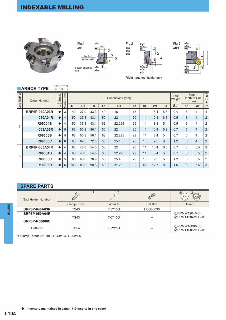
L104
W1
øD7
øD6øD1
A2
øD9
ap
L1L7
L8
øD7øD9
øD8øD6øD1
W1
ap
A2
L1
L8L7
øD9øD7
W1 L8
L7L1
apøD8øD6øD1
A2
ø40 ø50ø63ø80
ø100
Tool Holder Number * z x
Clamp Screw Wrench Set Bolt Insert
BRP6P-040A03R TS43 TKY15D HDS08030zRPMW1204M0pxRPMT1204M0E-JS
BRP6P-050A04R
―
BRP6P-R08006CTS43 TKY15D ─
BRP8P TS54 TKY25D ─ zRPMW1606M0pxRPMT1606M0E-JS
A.R :-7°─+5°R.R :-15°─0°y
Cuttin
g Edge
R (a)
Order Number
Sto
ck
Numb
er of
Teeth
Dimensions (mm)
ToolWeight
(kg)
Max. Depth of Cut
(mm)
Type
(Fig
.)
R D1 D6 D7 L1 D9 L7 D8 W1 L8 ap A2
6
BRP6P-040A03R a 3 40 27.9 33.3 40 16 18 ─ 8.4 5.6 0.4 6 4 1
-050A04R a 4 50 37.8 43.1 50 22 20 11 10.4 6.3 0.5 6 4 2
R05004B a 4 50 37.8 43.1 63 22.225 29 11 8.4 5 0.5 6 4 2
-063A05R a 5 63 50.8 56.1 50 22 20 11 10.4 6.3 0.7 6 4 2
R06305B a 5 63 50.8 56.1 63 22.225 29 11 8.4 5 0.7 6 4 2
R08006C a 6 80 67.8 72.8 50 25.4 26 13 9.5 6 1.2 6 4 2
8
BRP8P-063A04R a 4 63 46.8 54.5 50 22 20 11 10.4 6.3 0.7 8 5.5 2
R06304B a 4 63 46.8 54.5 63 22.225 29 11 8.4 5 0.7 8 5.5 2
R08005C a 5 80 63.8 70.9 50 25.4 26 13 9.5 6 1.2 8 5.5 2
R10006D a 6 100 83.8 90.6 50 31.75 32 45 12.7 8 1.6 8 5.5 3
MIL
LIN
GINDEXABLE MILLING
SPARE PARTS
* Clamp Torque (N • m) : TS43=3.5, TS54=7.5
Set Bolt (Attached)
Set an attached bolt.
Fig.1 Fig.2 Fig.3
ARBOR TYPE
Right hand tool holder only.
a : Inventory maintained in Japan. (10 inserts in one case)
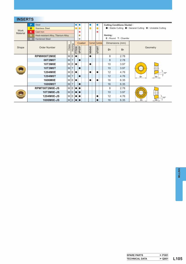
L105
D1 S111°
S1
11°
D1
WorkMaterial
P Steel M Stainless Steel
K Cast Iron
S Heat-resistant Alloy, Titanium Alloy
H Hardened Steel
Shape Order Number
Cla
ss
Hon
ing
Coated Cermet Carbide Dimensions (mm)
Geometry
F703
0VP
15TF
NX45
45
UTi2
0T
D1 S1
RPMW08T2M0E M E a a 8 2.7808T2M0T M T a 8 2.7810T3M0E M E a a 10 3.9710T3M0T M T a 10 3.971204M0E M E a a a 12 4.761204M0T M T a 12 4.761606M0E M E a a a 16 6.351606M0T M T a 16 6.35
RPMT08T2M0E-JS M E a a 8 2.7810T3M0E-JS M E a a 10 3.971204M0E-JS M E a a a 12 4.761606M0E-JS M E a a a 16 6.35
SPARE PARTS P001 TECHNICAL DATA Q001
MIL
LIN
G
INSERTSCutting Conditions (Guide) : : Stable Cutting : General Cutting : Unstable Cutting
Honing : E : Round T : Chamfer
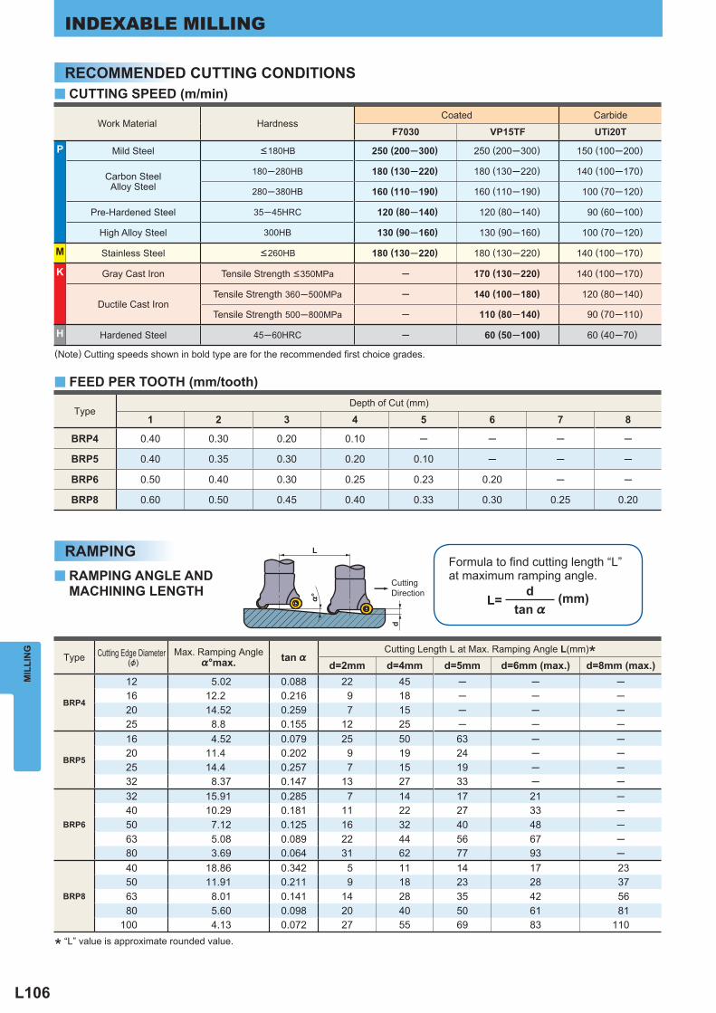
L106
%°
d
L
Work Material Hardness Coated Carbide
F7030 VP15TF UTi20T
P Mild Steel <180HB 250 (200─300) 250 (200─300) 150 (100─200)
Carbon SteelAlloy Steel
180─280HB 180 (130─220) 180 (130─220) 140 (100─170)
280─380HB 160 (110─190) 160 (110─190) 100 (70─120)
Pre-Hardened Steel 35─45HRC 120 (80─140) 120 (80─140) 90 (60─100)
High Alloy Steel 300HB 130 (90─160) 130 (90─160) 100 (70─120)
M Stainless Steel <260HB 180 (130─220) 180 (130─220) 140 (100─170)
K Gray Cast Iron Tensile Strength <350MPa ─ 170 (130─220) 140 (100─170)
Ductile Cast Iron Tensile Strength 360─500MPa ─ 140 (100─180) 120 (80─140)
Tensile Strength 500─800MPa ─ 110 (80─140) 90 (70─110)
H Hardened Steel 45─60HRC ─ 60 (50─100) 60 (40─70)
Type Depth of Cut (mm)
1 2 3 4 5 6 7 8
BRP4 0.40 0.30 0.20 0.10 ─ ─ ─ ─
BRP5 0.40 0.35 0.30 0.20 0.10 ─ ─ ─
BRP6 0.50 0.40 0.30 0.25 0.23 0.20 ─ ─
BRP8 0.60 0.50 0.45 0.40 0.33 0.30 0.25 0.20
L=d
tan %
Type Cutting Edge Diameter (&)
Max. Ramping Angle %°max. tan %
Cutting Length L at Max. Ramping Angle L(mm) *
d=2mm d=4mm d=5mm d=6mm (max.) d=8mm (max.)
BRP4
12 5.02 0.088 22 45 ─ ─ ─16 12.2 0.216 9 18 ─ ─ ─20 14.52 0.259 7 15 ─ ─ ─25 8.8 0.155 12 25 ─ ─ ─
BRP5
16 4.52 0.079 25 50 63 ─ ─20 11.4 0.202 9 19 24 ─ ─25 14.4 0.257 7 15 19 ─ ─32 8.37 0.147 13 27 33 ─ ─
BRP6
32 15.91 0.285 7 14 17 21 ─40 10.29 0.181 11 22 27 33 ─50 7.12 0.125 16 32 40 48 ─63 5.08 0.089 22 44 56 67 ─80 3.69 0.064 31 62 77 93 ─
BRP8
40 18.86 0.342 5 11 14 17 2350 11.91 0.211 9 18 23 28 3763 8.01 0.141 14 28 35 42 5680 5.60 0.098 20 40 50 61 81
100 4.13 0.072 27 55 69 83 110
y
y
y
MIL
LIN
GINDEXABLE MILLING
CUTTING SPEED (m/min)
FEED PER TOOTH (mm/tooth)
RAMPING ANGLE ANDMACHINING LENGTH
(Note) Cutting speeds shown in bold type are for the recommended fi rst choice grades.
Formula to fi nd cutting length “L”at maximum ramping angle.
(mm)
* “L” value is approximate rounded value.
CuttingDirection
RECOMMENDED CUTTING CONDITIONS
RAMPING
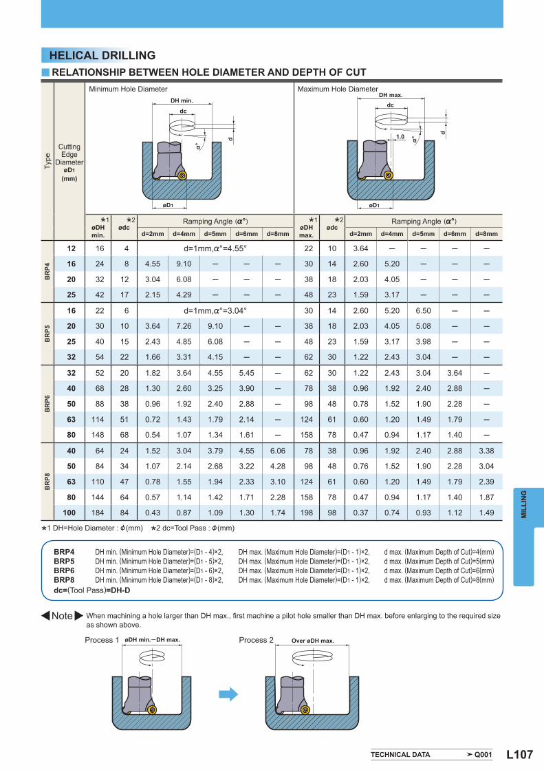
L107
dc
d
øD1
dc
d1.0
øD1%
° %°
Type
Cutting Edge
Diameter øD1
(mm)
Minimum Hole Diameter Maximum Hole Diameter
* 1øDHmin.
* 2ødc Ramping Angle (%°) * 1øDH
max. * 2ødc
Ramping Angle (%°)
d=2mm d=4mm d=5mm d=6mm d=8mm d=2mm d=4mm d=5mm d=6mm d=8mm
BR
P4
12 16 4 d=1mm,%°=4.55° 22 10 3.64 ─ ─ ─ ─
16 24 8 4.55 9.10 ─ ─ ─ 30 14 2.60 5.20 ─ ─ ─
20 32 12 3.04 6.08 ─ ─ ─ 38 18 2.03 4.05 ─ ─ ─
25 42 17 2.15 4.29 ─ ─ ─ 48 23 1.59 3.17 ─ ─ ─
BR
P5
16 22 6 d=1mm,%°=3.04° 30 14 2.60 5.20 6.50 ─ ─
20 30 10 3.64 7.26 9.10 ─ ─ 38 18 2.03 4.05 5.08 ─ ─
25 40 15 2.43 4.85 6.08 ─ ─ 48 23 1.59 3.17 3.98 ─ ─
32 54 22 1.66 3.31 4.15 ─ ─ 62 30 1.22 2.43 3.04 ─ ─
BR
P6
32 52 20 1.82 3.64 4.55 5.45 ─ 62 30 1.22 2.43 3.04 3.64 ─
40 68 28 1.30 2.60 3.25 3.90 ─ 78 38 0.96 1.92 2.40 2.88 ─
50 88 38 0.96 1.92 2.40 2.88 ─ 98 48 0.78 1.52 1.90 2.28 ─
63 114 51 0.72 1.43 1.79 2.14 ─ 124 61 0.60 1.20 1.49 1.79 ─
80 148 68 0.54 1.07 1.34 1.61 ─ 158 78 0.47 0.94 1.17 1.40 ─
BR
P8
40 64 24 1.52 3.04 3.79 4.55 6.06 78 38 0.96 1.92 2.40 2.88 3.38
50 84 34 1.07 2.14 2.68 3.22 4.28 98 48 0.76 1.52 1.90 2.28 3.04
63 110 47 0.78 1.55 1.94 2.33 3.10 124 61 0.60 1.20 1.49 1.79 2.39
80 144 64 0.57 1.14 1.42 1.71 2.28 158 78 0.47 0.94 1.17 1.40 1.87
100 184 84 0.43 0.87 1.09 1.30 1.74 198 98 0.37 0.74 0.93 1.12 1.49
y
BRP4BRP5BRP6BRP8
TECHNICAL DATA Q001
MIL
LIN
G
DH min. (Minimum Hole Diameter)=(D1 - 4)×2,DH min. (Minimum Hole Diameter)=(D1 - 5)×2,DH min. (Minimum Hole Diameter)=(D1 - 6)×2,DH min. (Minimum Hole Diameter)=(D1 - 8)×2,
DH max. (Maximum Hole Diameter)=(D1 - 1)×2,DH max. (Maximum Hole Diameter)=(D1 - 1)×2,DH max. (Maximum Hole Diameter)=(D1 - 1)×2,DH max. (Maximum Hole Diameter)=(D1 - 1)×2,
d max. (Maximum Depth of Cut)=4(mm)d max. (Maximum Depth of Cut)=5(mm)d max. (Maximum Depth of Cut)=6(mm)d max. (Maximum Depth of Cut)=8(mm)
dc=(Tool Pass)=DH-D
When machining a hole larger than DH max., fi rst machine a pilot hole smaller than DH max. before enlarging to the required sizeas shown above.
Note
Process 1 Process 2
RELATIONSHIP BETWEEN HOLE DIAMETER AND DEPTH OF CUT
*1 DH=Hole Diameter : & (mm) *2 dc=Tool Pass : & (mm)
DH min.DH max.
øDH min.─DH max. Over øDH max.
HELICAL DRILLING
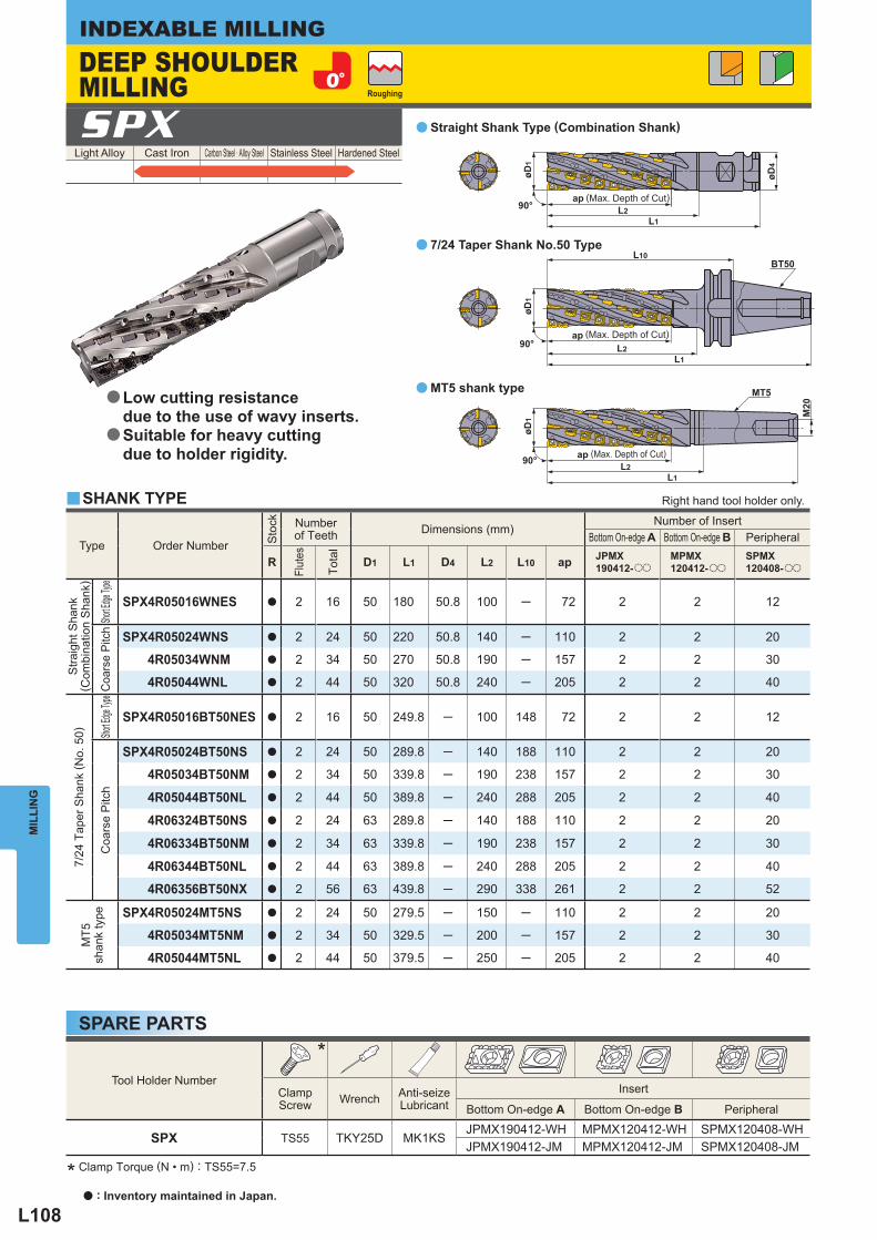
L108
90°L1
L2ap
øD4
øD1
90°L1
L10BT50
L2ap
øD1
90°
L1L2
ap
MT5
M20
øD1
Light Alloy Cast Iron Carbon Steel · Alloy Steel Stainless Steel Hardened Steel SPX
Type
Order Number
Sto
ck
Number of Teeth Dimensions (mm)
Number of Insert Bottom On-edge A Bottom On-edge B Peripheral
R
Flut
es
Tota
l
D1 L1 D4 L2 L10 ap JPMX190412-oo
MPMX120412-oo
SPMX120408-oo
Stra
ight
Sha
nk( C
ombi
natio
n S
hank
)
Short E
dge Ty
pe
SPX4R05016WNES a 2 16 50 180 50.8 100 ─ 72 2 2 12
Coa
rse
Pitc
h
SPX4R05024WNS a 2 24 50 220 50.8 140 ─ 110 2 2 20
4R05034WNM a 2 34 50 270 50.8 190 ─ 157 2 2 30
4R05044WNL a 2 44 50 320 50.8 240 ─ 205 2 2 40
7/24
Tap
er S
hank
( No.
50)
Short E
dge Ty
pe
SPX4R05016BT50NES a 2 16 50 249.8 ─ 100 148 72 2 2 12
Coa
rse
Pitc
h
SPX4R05024BT50NS a 2 24 50 289.8 ─ 140 188 110 2 2 20
4R05034BT50NM a 2 34 50 339.8 ─ 190 238 157 2 2 30
4R05044BT50NL a 2 44 50 389.8 ─ 240 288 205 2 2 40
4R06324BT50NS a 2 24 63 289.8 ─ 140 188 110 2 2 20
4R06334BT50NM a 2 34 63 339.8 ─ 190 238 157 2 2 30
4R06344BT50NL a 2 44 63 389.8 ─ 240 288 205 2 2 40
4R06356BT50NX a 2 56 63 439.8 ─ 290 338 261 2 2 52
MT5
shan
k ty
pe
SPX4R05024MT5NS a 2 24 50 279.5 ─ 150 ─ 110 2 2 20
4R05034MT5NM a 2 34 50 329.5 ─ 200 ─ 157 2 2 30
4R05044MT5NL a 2 44 50 379.5 ─ 250 ─ 205 2 2 40
Tool Holder Number
*
Clamp Screw Wrench Anti-seize
Lubricant Insert
Bottom On-edge A Bottom On-edge B Peripheral
SPX TS55 TKY25D MK1KSJPMX190412-WH MPMX120412-WH SPMX120408-WHJPMX190412-JM MPMX120412-JM SPMX120408-JM
y
a
a
a
MIL
LIN
GINDEXABLE MILLING
* Clamp Torque (N • m) : TS55=7.5
SPARE PARTS
Roughing
SHANK TYPE
DEEP SHOULDER MILLING
(Max. Depth of Cut)
(Max. Depth of Cut)
(Max. Depth of Cut)
Right hand tool holder only.
Low cutting resistance due to the use of wavy inserts.Suitable for heavy cutting due to holder rigidity.
a
a
Straight Shank Type (Combination Shank)
7/24 Taper Shank No.50 Type
MT5 shank type
a : Inventory maintained in Japan.
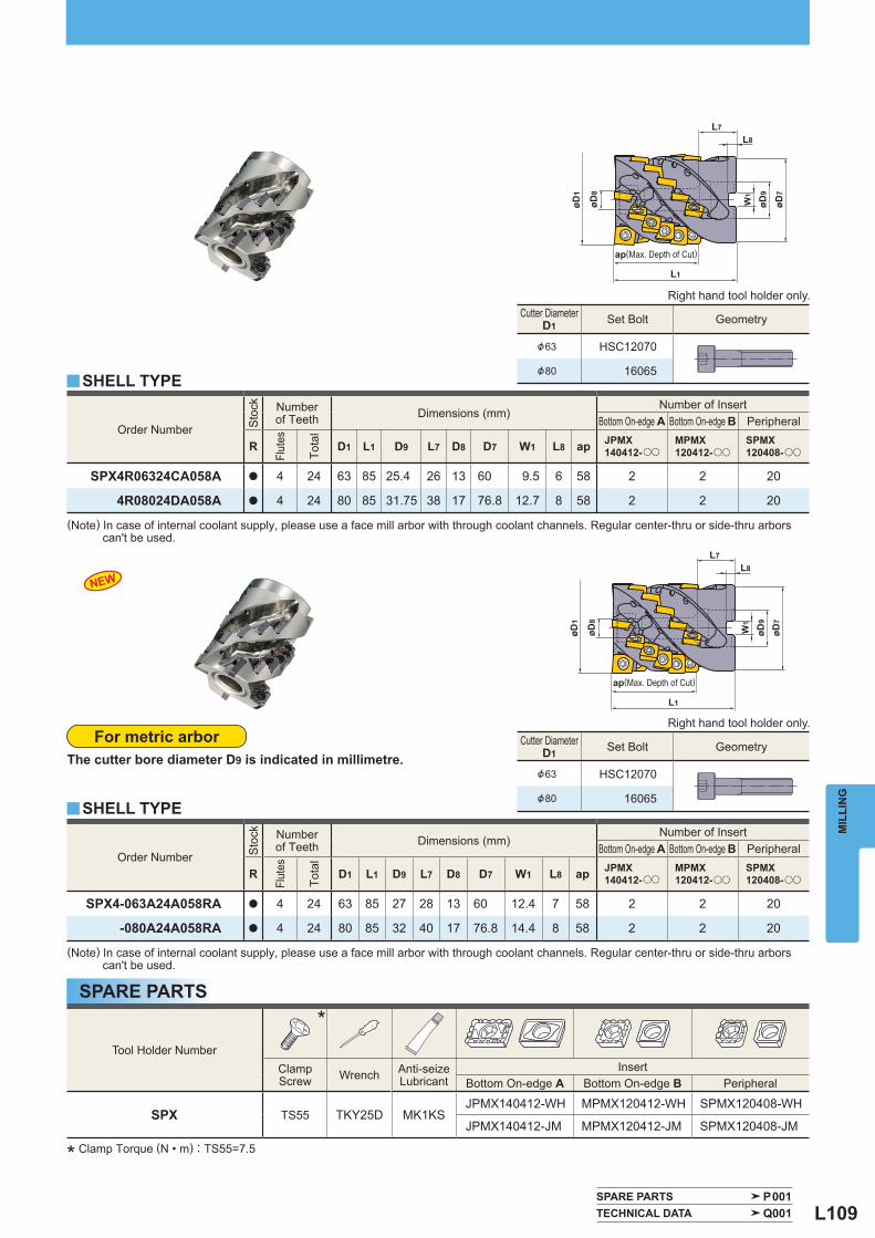
L109
øD8
L1
L7L8
øD1
øD9
W1
øD7
L7
øD8
L1
L8øD
1
øD9
W1
øD7
Tool Holder Number
*
Clamp Screw Wrench Anti-seize
Lubricant Insert
Bottom On-edge A Bottom On-edge B Peripheral
SPX TS55 TKY25D MK1KSJPMX140412-WH MPMX120412-WH SPMX120408-WH
JPMX140412-JM MPMX120412-JM SPMX120408-JM
Order Number
Sto
ck
Number of Teeth Dimensions (mm)
Number of Insert Bottom On-edge A Bottom On-edge B Peripheral
R
Flut
es
Tota
l
D1 L1 D9 L7 D8 D7 W1 L8 ap JPMX140412-oo
MPMX120412-oo
SPMX120408-oo
SPX4R06324CA058A a 4 24 63 85 25.4 26 13 60 9.5 6 58 2 2 20
4R08024DA058A a 4 24 80 85 31.75 38 17 76.8 12.7 8 58 2 2 20
y
SPARE PARTS P001 TECHNICAL DATA Q001
Cutter Diameter D1 Set Bolt Geometry
&63 HSC12070
&80 16065
NEW
Order Number
Sto
ck
Number of Teeth Dimensions (mm)
Number of Insert Bottom On-edge A Bottom On-edge B Peripheral
R
Flut
es
Tota
l
D1 L1 D9 L7 D8 D7 W1 L8 ap JPMX140412-oo
MPMX120412-oo
SPMX120408-oo
SPX4-063A24A058RA a 4 24 63 85 27 28 13 60 12.4 7 58 2 2 20
-080A24A058RA a 4 24 80 85 32 40 17 76.8 14.4 8 58 2 2 20
y
Cutter Diameter D1 Set Bolt Geometry
&63 HSC12070
&80 16065
MIL
LIN
G
SPARE PARTS
* Clamp Torque (N • m) : TS55=7.5
ap(Max. Depth of Cut)
SHELL TYPE
Right hand tool holder only.
ap(Max. Depth of Cut)
For metric arborThe cutter bore diameter D9 is indicated in millimetre.
SHELL TYPE
(Note) In case of internal coolant supply, please use a face mill arbor with through coolant channels. Regular center-thru or side-thru arbors can't be used.
(Note) In case of internal coolant supply, please use a face mill arbor with through coolant channels. Regular center-thru or side-thru arbors can't be used.
Right hand tool holder only.
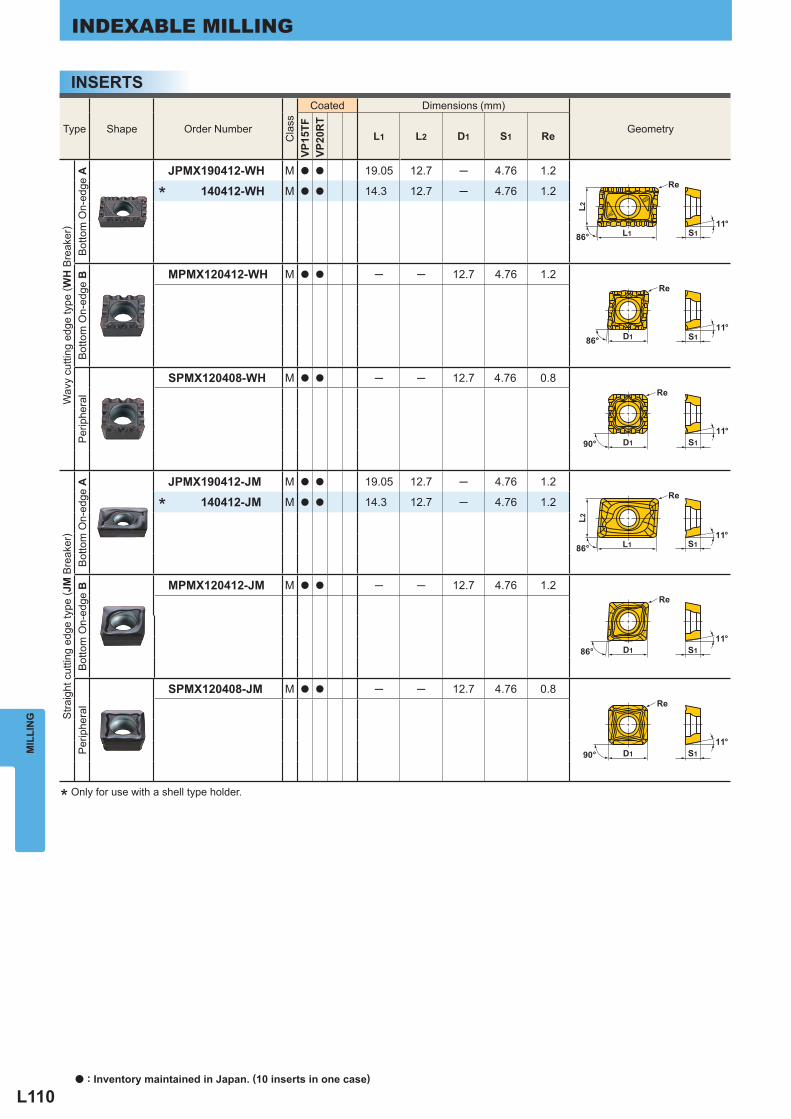
L110
S111°
86°
Re
L1
L2
S111°
D1
Re
86°
D1 S111°
90°
Re
S111°
D190°
Re
S111°
86° D1
Re
S111°
Re
86° L1
L2
Type Shape Order Number
Cla
ss
Coated Dimensions (mm)
Geometry
VP15
TFVP
20R
T
L1 L2 D1 S1 Re
Wav
y cu
tting
edg
e ty
pe ( W
H B
reak
er)
Bot
tom
On-
edge
A
JPMX190412-WH M a a 19.05 12.7 ─ 4.76 1.2
140412-WH M a a 14.3 12.7 ─ 4.76 1.2
Bot
tom
On-
edge
B
MPMX120412-WH M a a ─ ─ 12.7 4.76 1.2
Per
iphe
ral
SPMX120408-WH M a a ─ ─ 12.7 4.76 0.8
Stra
ight
cut
ting
edge
type
( JM
Bre
aker
)
Bot
tom
On-
edge
A
JPMX190412-JM M a a 19.05 12.7 ─ 4.76 1.2
140412-JM M a a 14.3 12.7 ─ 4.76 1.2
Bot
tom
On-
edge
B
MPMX120412-JM M a a ─ ─ 12.7 4.76 1.2
Per
iphe
ral
SPMX120408-JM M a a ─ ─ 12.7 4.76 0.8
*
*
MIL
LIN
GINDEXABLE MILLING
* Only for use with a shell type holder.
INSERTS
a : Inventory maintained in Japan. (10 inserts in one case)
L111
Work Material Hardness GradeBreaker
Cutting Speed vc
(m/min)
Depth of Cut ap
(mm)
Cutting Width ae
(mm)
Feed per Tooth fz
(mm/tooth)
P Mild Steel <180HB
VP15TFWH
120(100─140) ─4D1 ─5 0.15─0.25
VP15TFJM
120(100─140) ─2D1 ─10 0.15─0.25
Carbon SteelAlloy Steel 180─350HB
VP15TFWH
80(70─120) ─4D1 ─5 0.15─0.25
VP15TFJM
80(70─120) ─2D1 ─10 0.15─0.25
Alloy Tool Steel <300HB VP15TF
WH80
(60─100) ─4D1 ─5 0.10─0.20VP15TF
JM80
(60─100) ─2D1 ─10 0.10─0.20
M Stainless Steel <200HB
VP20RTWH
80(70─120) ─4D1 ─5 0.10─0.20
VP20RTJM
80(70─120) ─2D1 ─10 0.10─0.20
K Gray Cast Iron Tensile Strength
<350MPa
VP15TFWH
100(80─120) ─4D1 ─5 0.15─0.40
VP15TFJM
100(80─120) ─4D1 ─5 0.10─0.25
Ductile Cast Iron Tensile Strength <800MPa
VP15TFWH
80(60─100) ─4D1 ─5 0.15─0.35
VP15TFJM
80(60─100) ─4D1 ─5 0.10─0.20
S Ti Alloy <350HB
VP20RTWH
40(35─50) ─4D1 ─5 0.08─0.12
VP20RTJM
40(35─50) ─2D1 ─10 0.08─0.12
SPARE PARTS P001 TECHNICAL DATA Q001
y
Work Material Hardness GradeBreaker
Cutting Speed vc
(m/min)
Depth of Cut ap
(mm)
Cutting Width ae
(mm)
Feed per Tooth fz
(mm/tooth)
P Mild Steel <180HB
VP15TFWH
60(50─120) ─10 D1 0.10─0.25
VP15TFJM
60(50─120) ─10 D1 0.10─0.15
Carbon SteelAlloy Steel 180─350HB
VP15TFWH
60(50─100) ─10 D1 0.10─0.25
VP15TFJM
60(50─100) ─10 D1 0.10─0.15
Alloy Tool Steel <300HB VP15TF
WH50
(40─80) ─10 D1 0.10─0.25VP15TF
JM50
(40─80) ─10 D1 0.10─0.15
M Stainless Steel <200HB
VP20RTWH
60(50─120) ─10 D1 0.10─0.25
VP20RTJM
60(50─120) ─10 D1 0.10─0.15
K Gray Cast Iron Tensile Strength
<350MPa
VP15TFWH
50(40─80) ─50 D1 0.15─0.25
VP15TFJM
50(40─80) ─40 D1 0.10─0.20
Ductile Cast Iron Tensile Strength <800MPa
VP15TFWH
40(35─80) ─40 D1 0.15─0.25
VP15TFJM
40(35─80) ─30 D1 0.10─0.20
S Ti Alloy <350HB
VP20RTWH
35(30─50) ─10 D1 0.08─0.12
VP20RTJM
35(30─50) ─10 D1 0.08─0.12
y
MIL
LIN
G
RECOMMENDED CUTTING CONDITIONS (SHANK TYPE)CUTTING CONDITIONS FOR SHOULDER MILLING
(Note 1) The above cutting conditons are determined based on high rigidity machine and workpiece, where no vibration occurred. Please adjust processing conditions if the vibration is generated.
(Note 2) For tools with a cutting edge length of 200mm or more, please reduce the cutting speed and table feed by 10-20% and the width of cut by 50%.
(Note 3) If the cutting angle between the tool and workpiece exceeds 90º when machining corners ,Reduce the cutting speed and table feed by 10-20% and ae by 50%. Also if possible, set a radius cutting path for corners.
(Note 1) The above cutting conditons are determined based on high rigidity machine and workpiece, where no vibration occurred. Please adjust processing conditions if the vibration is generated.
(Note 2) For slotting, please use high rigidity tools such as SPX4R05016WNES/BT50NES.
SLOT MILLING
L112
Work Material Hardness GradeBreaker
Cutting Speed vc
(m/min)
Depth of Cut ap
(mm)
Cutting Width ae
(mm)
Feed per Tooth fz
(mm/tooth)
P Mild Steel <180HB VP15TF
JM
120(100─140) ─0.5D1 ─10 0.15─0.30
120(100─140) 0.5D1─ ─10 0.15─0.25
Carbon SteelAlloy Steel 180─350HB VP15TF
JM
120(80─130) ─0.5D1 ─10 0.15─0.30
100(80─120) 0.5D1─ ─10 0.15─0.25
Alloy Tool Steel <300HB VP15TFJM
100(60─110) ─0.5D1 ─10 0.10─0.20
80(60─100) 0.5D1─ ─10 0.10─0.15
M Stainless Steel <200HB VP20RT
JM
140(100─150) ─0.5D1 ─10 0.10─0.25
120(100─140) 0.5D1─ ─10 0.10─0.20
K
Gray Cast Iron Tensile Strength <350MPa
VP15TFWH
120(80─130) ─0.5D1 ─10 0.25─0.40
100(80─120) 0.5D1─ ─10 0.25─0.40
VP15TFJM
120(80─130) ─0.5D1 ─10 0.15─0.30
100(80─120) 0.5D1─ ─10 0.15─0.25
Ductile Cast Iron Tensile Strength <800MPa
VP15TFWH
100(60─110) ─0.5D1 ─10 0.20─0.35
80(60─110) 0.5D1─ ─10 0.20─0.35
VP15TFJM
100(60─120) ─0.5D1 ─10 0.15─0.30
80(60─120) 0.5D1─ ─10 0.15─0.30
S Ti Alloy <350HB VP20RT
JM
45(35─50) ─0.5D1 ─10 0.08─0.10
40(35─50) 0.5D1─ ─10 0.08─0.10
y
Work Material Hardness GradeBreaker
Cutting Speed vc
(m/min)
Depth of Cut ap
(mm)
Cutting Width ae
(mm)
Feed per Tooth fz
(mm/tooth)
P Mild Steel <180HB VP15TFJM
120(100─140) ─10 D1 0.15─0.25
Carbon SteelAlloy Steel 180─350HB VP15TF
JM100
(80─120) ─0.25D1 D1 0.15─0.25
Alloy Tool Steel <300HB VP15TFJM
80(60─100) ─10 D1 0.10─0.20
M Stainless Steel <200HB VP20RTJM
100(80─140) ─10 D1 0.10─0.15
K
Gray Cast Iron Tensile Strength <350MPa
VP15TFWH
80(60─100) ─0.25D1 D1 0.10─0.25
60(50─100) ─0.6D1 D1 0.10─0.20
VP15TFJM
80(60─100) ─0.25D1 D1 0.10─0.20
60(50─100) ─0.6D1 D1 0.10─0.15
Ductile Cast Iron Tensile Strength <800MPa
VP15TFWH
80(60─100) ─0.25D1 D1 0.10─0.25
60(50─100) ─0.5D1 D1 0.10─0.20
VP15TFJM
80(60─100) ─0.25D1 D1 0.10─0.20
60(50─100) ─0.5D1 D1 0.10─0.15
S Ti Alloy <350HB VP20RTJM
40(35─50) ─0.25D1 D1 0.06─0.10
y
MIL
LIN
GINDEXABLE MILLING
RECOMMENDED CUTTING CONDITIONS (SHELL TYPE)CUTTING CONDITIONS FOR SHOULDER MILLING
(Note 1) The above cutting conditons are determined based on high rigidity machine and workpiece, where no vibration occurred. Please adjust processing conditions if the vibration is generated.
SLOT MILLING
(Note 1) The above cutting conditons are determined based on high rigidity machine and workpiece, where no vibration occurred. Please adjust processing conditions if the vibration is generated.
a : Inventory maintained in Japan.
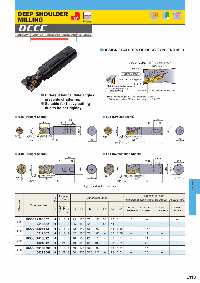
L113
RR°
L1L2
(90°)
L3
øD4
14 1936
R0.8
øD1
ap
(90°)RR°
øD4
1940
L1L2
øD1
R0.8
14
ap
30(90°)
RR°
øD4
14 1936
L2R0.8
L130
øD1
ap
(90°)40 45
47.8
46.5
øD4
L2L1
RR°
44.4517.78
øD1
R0.8 ap
Light Alloy Cast Iron Carbon Steel · Alloy Steel Stainless Steel Hardened Steel DCCC
Dia
met
er
Order Number
Sto
ck
Number of Teeth Dimensions (mm)
Number of Insert Peripheral and Bottom Inserts Bottom Insert (One pocket only)
R
Flut
es
Tota
l
Bot
tom
D1 L1 D4 L2 L3 ap RR° CCMX083508EN-A
CCMX09T308EN-p
ZCMX083508ER-A
ZCMX09T308ER-p
&25DCCCR2506S32 a 2 6 2 25 130 32 50 36 27 8° 5 ─ 1 ─
2510S32 a 2 10 2 25 150 32 70 56 44 8° 9 ─ 1 ─
&32DCCCR3208S32 a 2 8 2 32 140 32 60 ─ 43 8°36′ ─ 7 ─ 1
3212S32 a 2 12 2 32 160 32 80 ─ 63 8°36′ ─ 11 ─ 1
&40DCCCR4015S42 a 3 15 3 40 150 42 70 ─ 53 5°31′ ─ 14 ─ 1
4024S42 a 3 24 3 40 180 42 100 ─ 83 5°31′ ─ 23 ─ 1
&50DCCCR5018S508 a 3 18 3 50 175 50.8 90 ─ 63 5°51′ ─ 17 ─ 1
5027S508 a 3 27 3 50 205 50.8 120 ─ 93 5°51′ ─ 26 ─ 1
y
a
a
a
a
MIL
LIN
G
DESIGN FEATURES OF DCCC TYPE END MILL
&40 (Straight Shank)
&32 (Straight Shank)
Close Pitch Insert Position.
Clamp Screw
Insert : CCMX Type
Flute A
Flute B
80° corner
100°corner
&50 (Combination Shank)
Insert : ZCMX Type Cutter Body
Roughing
DEEP SHOULDER MILLING
(Max. Depth of Cut)
(Max. Depth of Cut) (Max. Depth of Cut)
(Max. Depth of Cut)
Right hand tool holder only.
a All 4 cutting edges of CCMX insert are utilized, 80° corners in fl ute "A" and 100° corners on fl ute "B".
a Additional body clearance reduces probability of chip jamming.
Different helical fl ute angles prevents chattering.Suitable for heavy cutting due to holder rigidity.
a
a
&25 (Straight Shank)
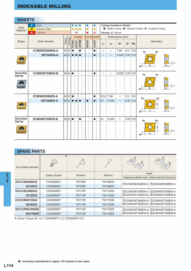
L114
D180° S1
ReRe
7°
D180° S1
ReRe
7°
L2
ReRe
S17°
80° L1
L2
Re
80° L1
Re
S17°
Tool Holder Number
* z
x
z
x
Clamp Screw Wrench Wrench Insert
Peripheral and Bottom Insert Bottom Insert (One Pocket Only)
DCCCR2506S32 CS300890T TKY08F TKY08DSzCCMX083508EN-A zZCMX083508ER-A
2510S32 CS300890T TKY08F TKY08DS
DCCCR3208S32 CS350990T TKY10F TKY10DS zCCMX09T308EN-AxCCMX09T308EN-B
zZCMX09T308ER-AxZCMX09T308ER-B3212S32 CS350990T TKY10F TKY10DS
DCCCR4015S42 CS350990T TKY10F TKY10DS zCCMX09T308EN-AxCCMX09T308EN-B
zZCMX09T308ER-AxZCMX09T308ER-B4024S42 CS350990T TKY10F TKY10DS
DCCCR5018S508 CS350990T TKY10F TKY10DS zCCMX09T308EN-AxCCMX09T308EN-B
zZCMX09T308ER-AxZCMX09T308ER-B5027S508 CS350990T TKY10F TKY10DS
WorkMaterial
P Steel M Stainless Steel K Cast Iron
Shape Order Number
Cla
ss
Hon
ing
Coated Cermet Carbide Dimensions (mm)
Geometry
F703
0VP
15TF
UP20
M
NX25
25
UTi2
0T
L1 L2 D1 S1 Re
CCMX083508EN-A M E a a a ─ ─ 7.94 3.5 0.809T308EN-A M E a a a a ─ ─ 9.525 3.97 0.8
Strong CuttingEdge Type
CCMX09T308EN-B M E a a ─ ─ 9.525 3.97 0.8
ZCMX083508ER-A M E a a 10.4 7.94 ─ 3.5 0.809T308ER-A M E a a a a a 12 9.525 ─ 3.97 0.8
Strong CuttingEdge Type
ZCMX09T308ER-B M E a a a 12 9.525 ─ 3.97 0.8
MIL
LIN
GINDEXABLE MILLING
INSERTS
SPARE PARTS
* Clamp Torque (N • m) : CS300890T=1.0, CS350990T=2.5
Cutting Conditions (Guide) : : Stable Cutting : General Cutting : Unstable Cutting
Honing : E : Round
a : Inventory maintained in Japan. (10 inserts in one case)
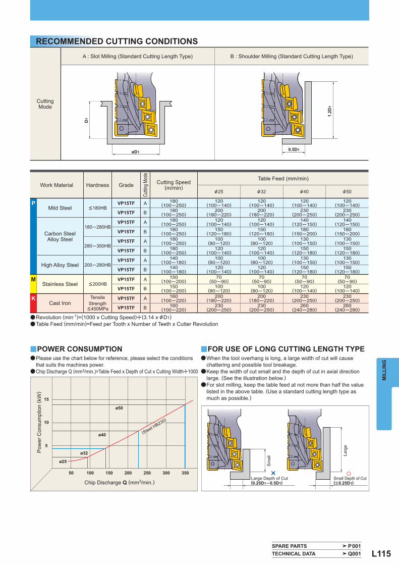
L115
1.2D
1
0.5D1øD1
D1
SPARE PARTS P001 TECHNICAL DATA Q001
CuttingMode
A : Slot Milling (Standard Cutting Length Type) B : Shoulder Milling (Standard Cutting Length Type)
Work Material Hardness Grade
Cuttin
g Mod
e
Cutting Speed(m/min)
Table Feed (mm/min)
&25 &32 &40 &50
P Mild Steel <180HB
VP15TF A 180(100─250)
120(100─140)
120(100─140)
120(100─140)
120(100─140)
VP15TF B 180(100─250)
200(180─220)
200(180─220)
230(200─250)
230(200─250)
Carbon SteelAlloy Steel
180─280HB VP15TF A 180
(100─250)120
(100─140)120
(100─140)140
(120─150)140
(120─150)
VP15TF B 180(100─250)
150(120─180)
150(120─180)
180(150─200)
180(150─200)
280─350HB VP15TF A 180
(100─250)100
(80─120)100
(80─120)130
(100─150)130
(100─150)
VP15TF B 180(100─250)
120(100─140)
120(100─140)
150(120─180)
150(120─180)
High Alloy Steel 200─280HB VP15TF A 140
(100─180)100
(80─120)100
(80─120)130
(100─150)130
(100─150)
VP15TF B 140(100─180)
120(100─140)
120(100─140)
150(120─180)
150(120─180)
M Stainless Steel <200HB
VP15TF A 150(100─200)
70(50─90)
70(50─90)
70(50─90)
70(50─90)
VP15TF B 150(100─200)
100(80─120)
100(80─120)
120(100─140)
120(100─140)
K Cast Iron
TensileStrength
<450MPa
VP15TF A 160(100─220)
200(180─220)
200(180─220)
230(200─250)
230(200─250)
VP15TF B 160(100─220)
230(200─250)
230(200─250)
260(240─280)
260(240─280)
y y
×50
ø25
ø32
ø40
ø50
5
10
15
100 150 200 250 300 350
MIL
LIN
G
RECOMMENDED CUTTING CONDITIONS
POWER CONSUMPTION FOR USE OF LONG CUTTING LENGTH TYPE
Large Depth of Cut (0.25D1─0.5D1)
Small Depth of Cut(<0.25D1)
(Steel HB230)
a Revolution (min-1)=(1000 x Cutting Speed)u(3.14 x &D1)a Table Feed (mm/min)=Feed per Tooth x Number of Teeth x Cutter Revolution
Chip Discharge Q (mm3/min.)
Pow
er C
onsu
mpt
ion
( kW
)
Sm
all La
rge
a Please use the chart below for reference, please select the conditions that suits the machines power.
a Chip Discharge Q (mm3/min.)=Table Feed x Depth of Cut x Cutting Widthu1000
a When the tool overhang is long, a large width of cut will cause chattering and possible tool breakage.
a Keep the width of cut small and the depth of cut in axial direction large. (See the illustration below.)
a For slot milling, keep the table feed at not more than half the value listed in the above table. (Use a standard cutting length type as much as possible.)
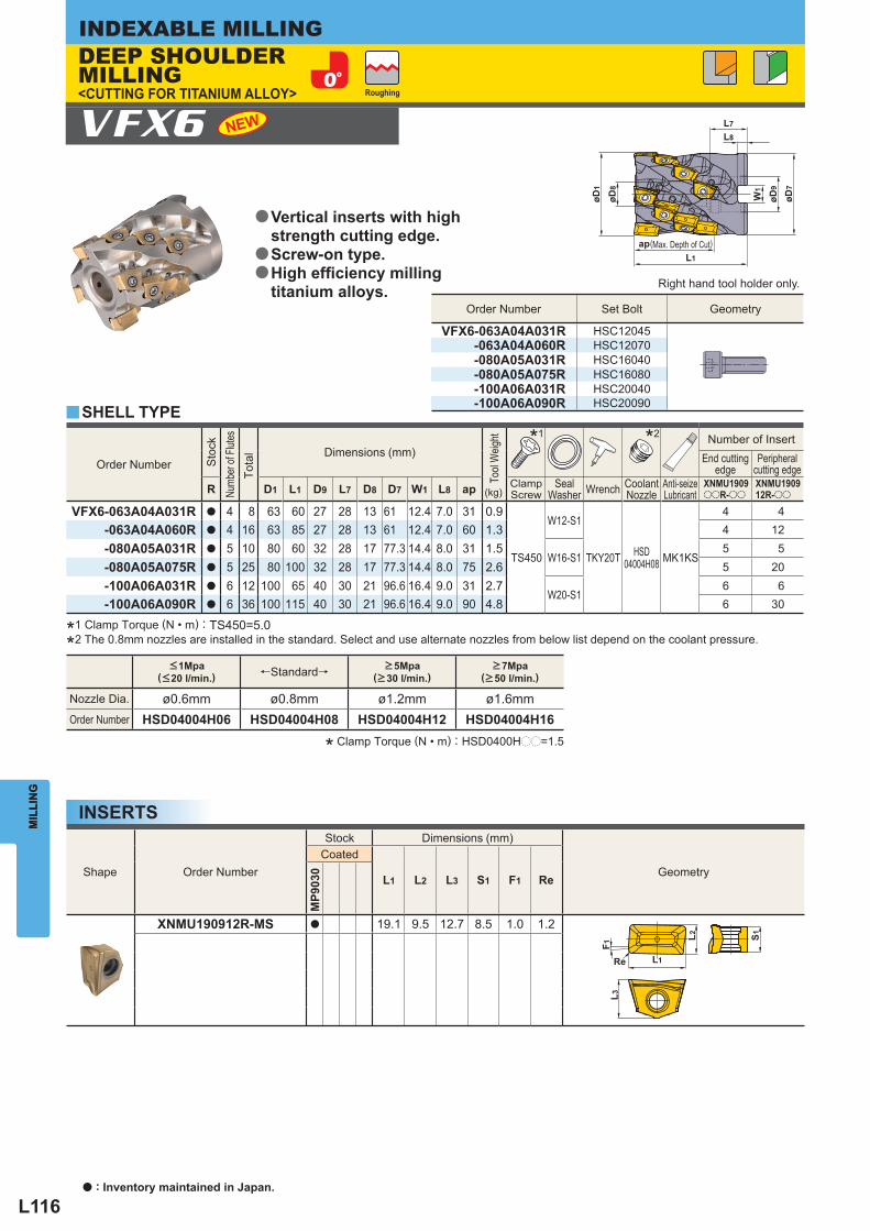
L116
L2
L1
L3
Re
S1
F1
L7
L8
øD9
øD7
W1
øD1
øD8
apL1
Order Number
Sto
ck
Numb
er of
Flutes
Tota
l
Dimensions (mm)
Tool
Weig
ht
(kg)
* 1 * 2 Number of Insert End cutting
edge Peripheral
cutting edge
R D1 L1 D9 L7 D8 D7 W1 L8 ap ClampScrew
SealWasher Wrench Coolant
Nozzle Anti-seizeLubricant
XNMU1909ooR-oo
XNMU190912R-oo
VFX6-063A04A031R a 4 8 63 60 27 28 13 61 12.4 7.0 31 0.9
TS450
W12-S1
TKY20T HSD04004H08 MK1KS
4 4 -063A04A060R a 4 16 63 85 27 28 13 61 12.4 7.0 60 1.3 4 12 -080A05A031R a 5 10 80 60 32 28 17 77.3 14.4 8.0 31 1.5
W16-S15 5
-080A05A075R a 5 25 80 100 32 28 17 77.3 14.4 8.0 75 2.6 5 20 -100A06A031R a 6 12 100 65 40 30 21 96.6 16.4 9.0 31 2.7
W20-S16 6
-100A06A090R a 6 36 100 115 40 30 21 96.6 16.4 9.0 90 4.8 6 30
Shape Order Number
Stock Dimensions (mm)
Geometry Coated
L1 L2 L3 S1 F1 Re
MP9
030
XNMU190912R-MS a 19.1 9.5 12.7 8.5 1.0 1.2
Order Number Set Bolt Geometry
VFX6-063A04A031R HSC12045 -063A04A060R HSC12070 -080A05A031R HSC16040 -080A05A075R HSC16080 -100A06A031R HSC20040 -100A06A090R HSC20090
<1Mpa( <20 l/min. ) ← Standard → >5Mpa
( >30 l/min. ) >7Mpa
( >50 l/min. )
Nozzle Dia. ø0.6mm ø0.8mm ø1.2mm ø1.6mm Order Number HSD04004H06 HSD04004H08 HSD04004H12 HSD04004H16
y
VFX6
MIL
LIN
GINDEXABLE MILLING
MIL
LIN
G
SHELL TYPE
(Max. Depth of Cut)
Right hand tool holder only.
INSERTS
a : Inventory maintained in Japan.
*1 Clamp Torque (N • m) : TS450=5.0
*2 The 0.8mm nozzles are installed in the standard. Select and use alternate nozzles from below list depend on the coolant pressure.
Roughing
Vertical inserts with high strength cutting edge.Screw-on type.High effi ciency milling titanium alloys.
a
a
a
DEEP SHOULDER MILLING<CUTTING FOR TITANIUM ALLOY>
* Clamp Torque (N • m) : HSD0400Hpp=1.5
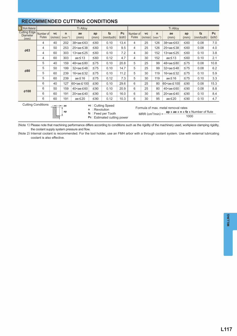
L117
S Work Material Ti Alloy Ti Alloy Cutting Edge
Diameter (mm)
Number of Flutes
vc (m/min)
n(min-1)
ae (mm)
ap (mm)
fz (mm/tooth)
Pc (kW)
Number of Flutes
vc (m/min)
n(min-1)
ae (mm)
ap (mm)
fz (mm/tooth)
Pc (kW)
&63
4 40 202 38<ae <63 <60 0.10 13.4 4 25 126 38<ae <63 <60 0.08 7.04 50 253 25<ae <38 <60 0.10 9.5 4 25 126 25<ae <38 <60 0.08 4.04 60 303 13<ae <25 <60 0.10 7.2 4 30 152 13<ae <25 <60 0.10 3.84 60 303 ae <13 <60 0.12 4.7 4 30 152 ae <13 <60 0.10 2.1
&80
5 40 159 48<ae <80 <75 0.10 20.8 5 25 99 48<ae <80 <75 0.08 10.85 50 199 32<ae <48 <75 0.10 14.7 5 25 99 32<ae <48 <75 0.08 6.25 60 239 16<ae <32 <75 0.10 11.2 5 30 119 16<ae <32 <75 0.10 5.95 60 239 ae <16 <75 0.12 7.3 5 30 119 ae <16 <75 0.10 3.3
&100
6 40 127 60<ae <100 <90 0.10 29.6 6 25 80 60<ae <100 <90 0.08 15.36 50 159 40<ae <60 <90 0.10 20.9 6 25 80 40<ae <60 <90 0.08 8.86 60 191 20<ae <40 <90 0.10 16.0 6 30 95 20<ae <40 <90 0.10 8.46 60 191 ae <20 <90 0.12 10.3 6 30 95 ae <20 <90 0.10 4.7
ae
ap
vc : n : fz : Pc :
MIL
LIN
G
Cutting Conditions Cutting SpeedRevolutionFeed per ToothEstimated cutting power
Formula of max. metal removal rates ap x ae x n x fz x Number of fl ute MRR (cm3/min) = 1000
RECOMMENDED CUTTING CONDITIONS
(Note 1) Please note that machining performance differs according to conditions such as the rigidity of the machinery used, workpiece clamping rigidity, the coolant supply system pressure and fl ow.
(Note 2) Internal coolant is recommended. For the tool holder, use an FMH arbor with a through coolant system. Use with external lubricating coolant is also effective.
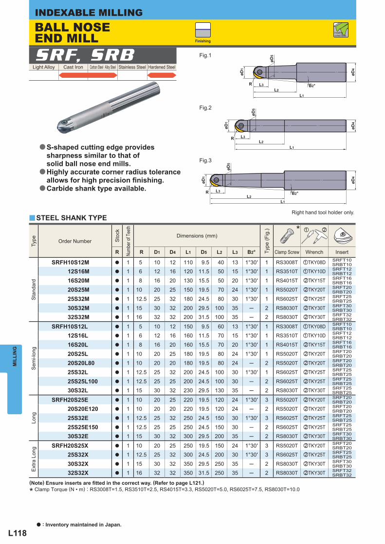
L118
øD1
øD5
øD4
L1L2
B2°L3R
øD1
øD4
R B2°
øD5
L1L2
L3
øD1
øD4
R
L1L2
øD5
L3
Light Alloy Cast Iron Carbon Steel · Alloy Steel Stainless Steel Hardened Steel SRF, SRB
y
Type
Order Number
Sto
ck
Numb
er of
Tee
th
Dimensions (mm)
Type
(Fig
.)
* z x
R R D1 D4 L1 D5 L2 L3 B2° Clamp Screw Wrench Insert
Sta
ndar
d
SRFH10S12M a 1 5 10 12 110 9.5 40 13 1°30′ 1 RS3008T zTKY08D SRFT10SRBT10
12S16M a 1 6 12 16 120 11.5 50 15 1°30′ 1 RS3510T zTKY10D SRFT12SRBT12
16S20M a 1 8 16 20 130 15.5 50 20 1°30′ 1 RS4015T xTKY15T SRFT16SRBT16
20S25M a 1 10 20 25 150 19.5 70 24 1°30′ 1 RS5020T xTKY20T SRFT20SRBT20
25S32M a 1 12.5 25 32 180 24.5 80 30 1°30′ 1 RS6025T xTKY25T SRFT25SRBT25
30S32M a 1 15 30 32 200 29.5 100 35 ─ 2 RS8030T xTKY30T SRFT30SRBT30
32S32M a 1 16 32 32 200 31.5 100 35 ─ 2 RS8030T xTKY30T SRFT32SRBT32
Sem
i-lon
g
SRFH10S12L a 1 5 10 12 150 9.5 60 13 1°30′ 1 RS3008T zTKY08D SRFT10SRBT10
12S16L a 1 6 12 16 160 11.5 70 15 1°30′ 1 RS3510T zTKY10D SRFT12SRBT12
16S20L a 1 8 16 20 160 15.5 70 20 1°30′ 1 RS4015T xTKY15T SRFT16SRBT16
20S25L a 1 10 20 25 180 19.5 80 24 1°30′ 1 RS5020T xTKY20T SRFT20SRBT20
20S20L80 a 1 10 20 20 180 19.5 80 24 ─ 2 RS5020T xTKY20T SRFT20SRBT20
25S32L a 1 12.5 25 32 200 24.5 100 30 1°30′ 1 RS6025T xTKY25T SRFT25SRBT25
25S25L100 a 1 12.5 25 25 200 24.5 100 30 ─ 2 RS6025T xTKY25T SRFT25SRBT25
30S32L a 1 15 30 32 230 29.5 130 35 ─ 2 RS8030T xTKY30T SRFT25SRBT25
Long
SRFH20S25E a 1 10 20 25 220 19.5 120 24 1°30′ 3 RS5020T xTKY20T SRFT20SRBT20
20S20E120 a 1 10 20 20 220 19.5 120 24 ─ 2 RS5020T xTKY20T SRFT20SRBT20
25S32E a 1 12.5 25 32 250 24.5 150 30 1°30′ 3 RS6025T xTKY25T SRFT25SRBT25
25S25E150 a 1 12.5 25 25 250 24.5 150 30 ─ 2 RS6025T xTKY25T SRFT25SRBT25
30S32E a 1 15 30 32 300 29.5 200 35 ─ 2 RS8030T xTKY30T SRFT30SRBT30
Ext
ra L
ong
SRFH20S25X a 1 10 20 25 250 19.5 150 24 1°30′ 3 RS5020T xTKY20T SRFT20SRBT20
25S32X a 1 12.5 25 32 300 24.5 200 30 1°30′ 3 RS6025T xTKY25T SRFT25SRBT25
30S32X a 1 15 30 32 350 29.5 250 35 ─ 2 RS8030T xTKY30T SRFT30SRBT30
32S32X a 1 16 32 32 350 31.5 250 35 ─ 2 RS8030T xTKY30T SRFT32SRBT32
MIL
LIN
GINDEXABLE MILLING
(Note) Ensure inserts are fi tted in the correct way. (Refer to page L121.)
* Clamp Torque (N • m) : RS3008T=1.5, RS3510T=2.5, RS4015T=3.3, RS5020T=5.0, RS6025T=7.5, RS8030T=10.0
Finishing
Fig.1
Fig.2
Fig.3
Right hand tool holder only.
Including curved faces
BALL NOSE END MILL
STEEL SHANK TYPE
S-shaped cutting edge provides sharpness similar to that of solid ball nose end mills.Highly accurate corner radius tolerance allows for high precision fi nishing.Carbide shank type available.
a
a
a
a : Inventory maintained in Japan.
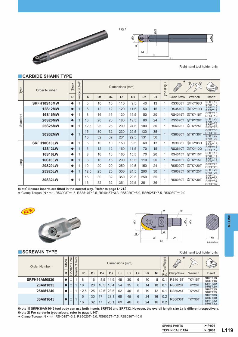
L119
øD1
øD4
R
øD5
L1L2
L3
M
øD4
øD5
øD1
L1L2 L11
A
A
RH1
SPARE PARTS P001 TECHNICAL DATA Q001
Type
Order Number
Sto
ck
Numb
er of
Tee
th
Dimensions (mm)
Type
(Fig
.)
* z x
R R D1 D4 L1 D5 L2 L3 Clamp Screw Wrench Insert
Sta
ndar
d
SRFH10S10MW a 1 5 10 10 110 9.5 40 13 1 RS3008T zTKY08D SRFT10SRBT10
12S12MW a 1 6 12 12 120 11.5 50 15 1 RS3510T zTKY10D SRFT12SRBT12
16S16MW a 1 8 16 16 130 15.5 50 20 1 RS4015T xTKY15T SRFT16SRBT16
20S20MW a 1 10 20 20 180 19.5 80 24 1 RS5020T xTKY20T SRFT20SRBT20
25S25MW a 1 12.5 25 25 200 24.5 100 30 1 RS6025T xTKY25T SRFT25SRBT25
30S32MW a 115 30 32 230 29.5 130 35
1 RS8030T xTKY30TSRFT30SRBT30
16 32 32 231 29.5 131 36 SRFT32SRBT32
Long
SRFH10S10LW a 1 5 10 10 150 9.5 60 13 1 RS3008T zTKY08D SRFT10SRBT10
12S12LW a 1 6 12 12 160 11.5 70 15 1 RS3510T zTKY10D SRFT12SRBT12
16S16LW a 1 8 16 16 160 15.5 70 20 1 RS4015T xTKY15T SRFT16SRBT16
16S16EW a 1 8 16 16 200 15.5 110 20 1 RS4015T xTKY15T SRFT16SRBT16
20S20LW a 1 10 20 20 250 19.5 150 24 1 RS5020T xTKY20T SRFT20SRBT20
25S25LW a 1 12.5 25 25 300 24.5 200 30 1 RS6025T xTKY25T SRFT25SRBT25
30S32LW a 115 30 32 350 29.5 250 35
1 RS8030T xTKY30TSRFT30SRBT30
16 32 32 351 29.5 251 36 SRFT32SRBT32
Order Number
Sto
ck
Coo
lant
Hol
e
Numb
er of
Tee
th
Dimensions (mm)
Tool
Wei
ght
(kg)
*
R R D1 D4 D5 L1 L2 L11 H1 M Clamp Screw Wrench Insert
SRFH16AM0830 a u 1 8 16 8.5 14.9 48 30 6 10 8 0.1 RS4015T TKY15T SRFT16SRBT16
20AM1035 a u 1 10 20 10.5 18.4 54 35 6 14 10 0.1 RS5020T TKY20T SRFT20SRBT20
25AM1240 a u 1 12.5 25 12.5 23.5 62 40 6 19 12 0.1 RS6025T TKY25T SRFT25SRBT25
30AM1645 a u 115 30 17 28.1 68 45 6 24 16 0.2
RS8030T TKY30TSRFT30SRBT30
16 32 17 28.1 69 46 6 24 16 0.2 SRFT32SRBT32
y
y
MIL
LIN
G
(Note) Ensure inserts are fi tted in the correct way. (Refer to page L121.)
* Clamp Torque (N • m) : RS3008T=1.5, RS3510T=2.5, RS4015T=3.3, RS5020T=5.0, RS6025T=7.5, RS8030T=10.0
(Note 1) SRFH30AM1645 tool body can use both inserts SRFT30 and SRFT32. However, the overall length size L1 is different respectively.(Note 2) For screw-in type arbors, refer to page L147.
* Clamp Torque (N • m) : RS4015T=3.3, RS5020T=5.0, RS6025T=7.5, RS8030T=10.0
Fig.1
Right hand tool holder only.
Right hand tool holder only.
CARBIDE SHANK TYPE
SCREW-IN TYPE
A-A section
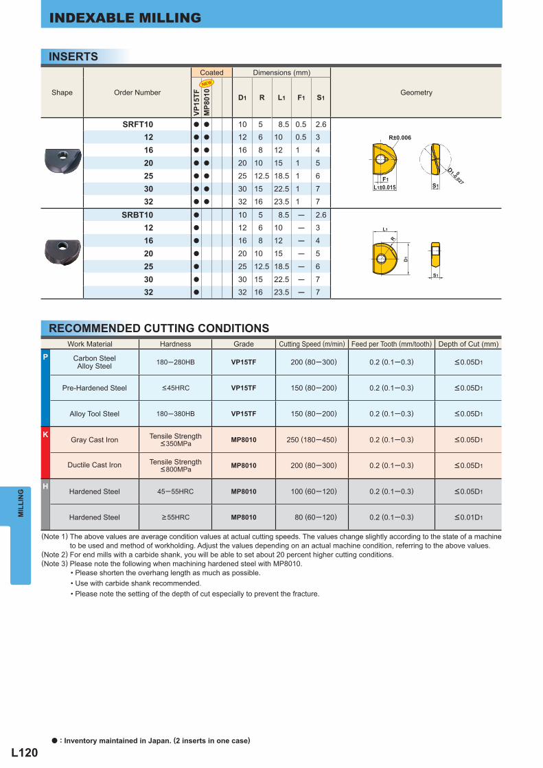
L120
S1
F1L1±0.015 S1
D1 0-0.027
R±0.006
D1
L1
R
Work Material Hardness Grade Cutting Speed (m/min) Feed per Tooth (mm/tooth) Depth of Cut (mm)
P Carbon SteelAlloy Steel 180─280HB VP15TF 200 (80─300) 0.2 (0.1─0.3) <0.05D1
Pre-Hardened Steel <45HRC VP15TF 150 (80─200) 0.2 (0.1─0.3) <0.05D1
Alloy Tool Steel 180─380HB VP15TF 150 (80─200) 0.2 (0.1─0.3) <0.05D1
K Gray Cast Iron Tensile Strength
<350MPa MP8010 250 (180─450) 0.2 (0.1─0.3) <0.05D1
Ductile Cast Iron Tensile Strength <800MPa MP8010 200 (80─300) 0.2 (0.1─0.3) <0.05D1
H Hardened Steel 45─55HRC MP8010 100 (60─120) 0.2 (0.1─0.3) <0.05D1
Hardened Steel >55HRC MP8010 80 (60─120) 0.2 (0.1─0.3) <0.01D1
Shape Order Number
Coated Dimensions (mm)
Geometry
VP15
TFM
P801
0
D1 R L1 F1 S1
SRFT10 a a 10 5 8.5 0.5 2.612 a a 12 6 10 0.5 3
16 a a 16 8 12 1 4
20 a a 20 10 15 1 5
25 a a 25 12.5 18.5 1 6
30 a a 30 15 22.5 1 732 a a 32 16 23.5 1 7
SRBT10 a 10 5 8.5 ─ 2.612 a 12 6 10 ─ 3
16 a 16 8 12 ─ 4
20 a 20 10 15 ─ 5
25 a 25 12.5 18.5 ─ 6
30 a 30 15 22.5 ─ 732 a 32 16 23.5 ─ 7
MIL
LIN
GINDEXABLE MILLING
RECOMMENDED CUTTING CONDITIONS
(Note 1) The above values are average condition values at actual cutting speeds. The values change slightly according to the state of a machine to be used and method of workholding. Adjust the values depending on an actual machine condition, referring to the above values.(Note 2) For end mills with a carbide shank, you will be able to set about 20 percent higher cutting conditions.(Note 3) Please note the following when machining hardened steel with MP8010. • Please shorten the overhang length as much as possible. • Use with carbide shank recommended. • Please note the setting of the depth of cut especially to prevent the fracture.
INSERTS
a : Inventory maintained in Japan. (2 inserts in one case)
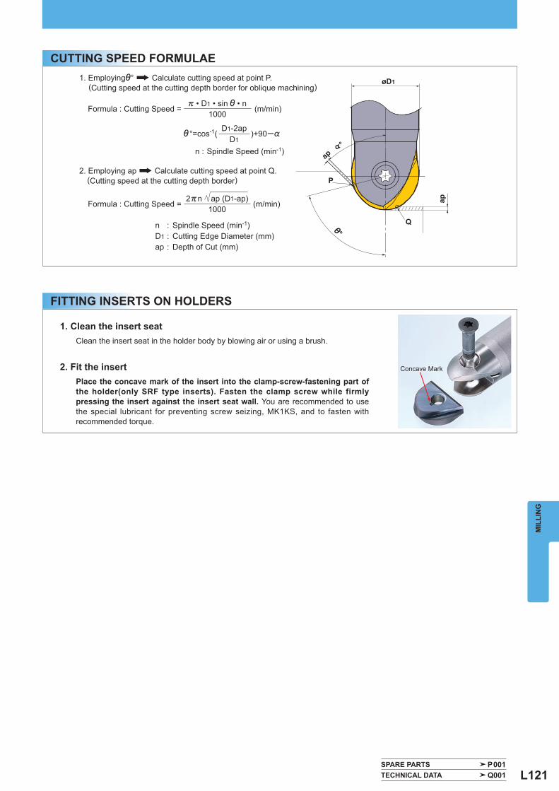
L121
'°
ap
Q
ap
P
%°
øD1
SPARE PARTS P001 TECHNICAL DATA Q001
MIL
LIN
G
FITTING INSERTS ON HOLDERS
CUTTING SPEED FORMULAE
Concave Mark
1. Employing'° Calculate cutting speed at point P. (Cutting speed at the cutting depth border for oblique machining)
Formula : Cutting Speed = ) • D1 • sin ' • n
(m/min)1000
'°=cos-1(D1-2ap
)+90─%D1
n : Spindle Speed (min-1)
2. Employing ap Calculate cutting speed at point Q. (Cutting speed at the cutting depth border)
Formula : Cutting Speed = 2)n ap (D1-ap)
(m/min)1000
n : Spindle Speed (min-1)D1 : Cutting Edge Diameter (mm)ap : Depth of Cut (mm)
1. Clean the insert seat Clean the insert seat in the holder body by blowing air or using a brush.
2. Fit the insertPlace the concave mark of the insert into the clamp-screw-fastening part of the holder(only SRF type inserts). Fasten the clamp screw while firmly pressing the insert against the insert seat wall. You are recommended to use the special lubricant for preventing screw seizing, MK1KS, and to fasten with recommended torque.
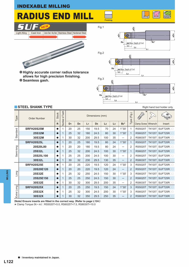
L122
øD4
L1L2
L3øD
1Re B2°
øD5
ap
øD4
L1L2
L3
øD1
Re
øD5
ap
øD1
øD5
øD4
L1L2
B2°
L3
Re ap
R
Light Alloy Cast Iron Carbon Steel · Alloy Steel Stainless Steel Hardened Steel SUF
y
Type
Order Number
Sto
ck
Numb
er of
Tee
th
Dimensions (mm)
Type
(Fig
.)
*
R D1 D4 L1 D5 L2 L3 B2° Clamp Screw Wrench Insert
Sta
ndar
d
SRFH20S25M a 1 20 25 150 19.5 70 24 1°30′ 1 RS5020T TKY20T SUFT20Rpp
25S32M a 1 25 32 180 24.5 80 30 1°30′ 1 RS6025T TKY25T SUFT25Rpp
30S32M a 1 30 32 200 29.5 100 35 ─ 2 RS8030T TKY30T SUFT30Rpp
Sem
i-lon
g
SRFH20S25L a 1 20 25 180 19.5 80 24 1°30′ 1 RS5020T TKY20T SUFT20Rpp
20S20L80 a 1 20 20 180 19.5 80 24 ─ 2 RS5020T TKY20T SUFT20Rpp
25S32L a 1 25 32 200 24.5 100 30 1°30′ 1 RS6025T TKY25T SUFT25Rpp
25S25L100 a 1 25 25 200 24.5 100 30 ─ 2 RS6025T TKY25T SUFT25Rpp
30S32L a 1 30 32 230 29.5 130 35 ─ 2 RS8030T TKY30T SUFT30Rpp
Long
SRFH20S25E a 1 20 25 220 19.5 120 24 1°30′ 3 RS5020T TKY20T SUFT20Rpp
20S20E120 a 1 20 20 220 19.5 120 24 ─ 2 RS5020T TKY20T SUFT20Rpp
25S32E a 1 25 32 250 24.5 150 30 1°30′ 3 RS6025T TKY25T SUFT25Rpp
25S25E150 a 1 25 25 250 24.5 150 30 ─ 2 RS6025T TKY25T SUFT25Rpp
30S32E a 1 30 32 300 29.5 200 35 ─ 2 RS8030T TKY30T SUFT30Rpp
Ext
ra L
ong
SRFH20S25X a 1 20 25 250 19.5 150 24 1°30′ 3 RS5020T TKY20T SUFT20Rpp
25S32X a 1 25 32 300 24.5 200 30 1°30′ 3 RS6025T TKY25T SUFT25Rpp
30S32X a 1 30 32 350 29.5 250 35 ─ 2 RS8030T TKY30T SUFT30Rpp
MIL
LIN
GINDEXABLE MILLING
(Note) Ensure inserts are fi tted in the correct way. (Refer to page L124.)
* Clamp Torque (N • m) : RS5020T=5.0, RS6025T=7.5, RS8030T=10.0
STEEL SHANK TYPE
Fig.1
Fig.2
Fig.3
(Max. Depth of Cut)
(Max. Depth of Cut)
(Max. Depth of Cut)
Highly accurate corner radius tolerance allows for high precision fi nishing.Seamless gash.
a
a
Right hand tool holder only.
a : Inventory maintained in Japan.
RADIUS END MILL Including Flat faces
Finishing
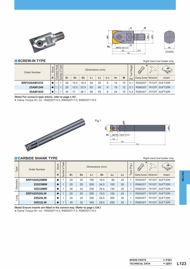
L123
M
øD4
øD5
øD1
L1L2 L11
A
A
Re ap
øD1
øD4
Re
øD5
L1L2
L3
ap
H1
Order Number
Sto
ck
Coo
lant
Hol
e
Numb
er of
Tee
th
Dimensions (mm)
Tool
Wei
ght
(kg)
*
R D1 D4 D5 L1 L2 L11 H1 M Clamp Screw Wrench Insert
SRFH20AM1035 a u 1 20 10.5 18.4 54 35 6 14 10 0.1 RS5020T TKY20T SUFT20Rpp
25AM1240 a u 1 25 12.5 23.5 62 40 6 19 12 0.1 RS6025T TKY25T SUFT25Rpp
30AM1645 a u 1 30 17 28.1 68 45 6 24 16 0.2 RS8030T TKY30T SUFT30Rpp
y
Type
Order Number
Sto
ck
Numb
er of
Tee
th
Dimensions (mm)
Type
(Fig
.)
*
R D1 D4 L1 D5 L2 L3 Clamp Screw Wrench Insert
Sta
ndar
d
SRFH20S20MW a 1 20 20 180 19.5 80 24 1 RS5020T TKY20T SUFT20Rpp
25S25MW a 1 25 25 200 24.5 100 30 1 RS6025T TKY25T SUFT25Rpp
30S32MW a 1 30 32 230 29.5 130 35 1 RS8030T TKY30T SUFT30Rpp
Long
SRFH20S20LW a 1 20 20 250 19.5 150 24 1 RS5020T TKY20T SUFT20Rpp
25S25LW a 1 25 25 300 24.5 200 30 1 RS6025T TKY25T SUFT25Rpp
30S32LW a 1 30 32 350 29.5 250 35 1 RS8030T TKY30T SUFT30Rpp
y
SPARE PARTS P001 TECHNICAL DATA Q001
MIL
LIN
G
Right hand tool holder only. SCREW-IN TYPE
A-A section
(Max. Depth of Cut)
(Note) For screw-in type arbors, refer to page L147.
* Clamp Torque (N • m) : RS5020T=5.0, RS6025T=7.5, RS8030T=10.0
(Note) Ensure inserts are fi tted in the correct way. (Refer to page L124.)
* Clamp Torque (N • m) : RS5020T=5.0, RS6025T=7.5, RS8030T=10.0
Fig.1
Right hand tool holder only. CARBIDE SHANK TYPE
(Max. Depth of Cut)
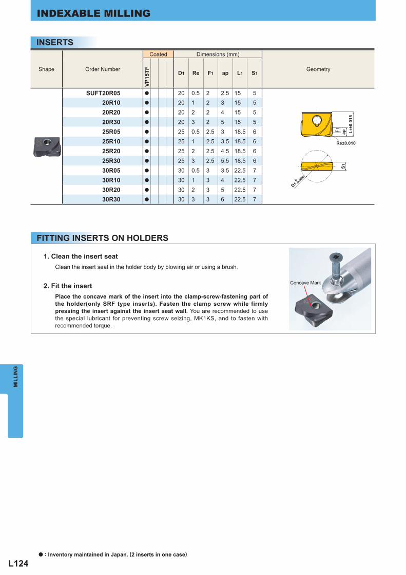
L124
D1
S1F1 ap L1
±0.0
15
Re±0.010
0-0.02
0
Shape Order Number
Coated Dimensions (mm)
Geometry
VP15
TF D1 Re F1 ap L1 S1
SUFT20R05 a 20 0.5 2 2.5 15 520R10 a 20 1 2 3 15 5
20R20 a 20 2 2 4 15 5
20R30 a 20 3 2 5 15 5
25R05 a 25 0.5 2.5 3 18.5 6
25R10 a 25 1 2.5 3.5 18.5 6
25R20 a 25 2 2.5 4.5 18.5 6
25R30 a 25 3 2.5 5.5 18.5 6
30R05 a 30 0.5 3 3.5 22.5 7
30R10 a 30 1 3 4 22.5 7
30R20 a 30 2 3 5 22.5 730R30 a 30 3 3 6 22.5 7
MIL
LIN
GINDEXABLE MILLING
INSERTS
FITTING INSERTS ON HOLDERS
Concave Mark
1. Clean the insert seat Clean the insert seat in the holder body by blowing air or using a brush.
2. Fit the insertPlace the concave mark of the insert into the clamp-screw-fastening part of the holder(only SRF type inserts). Fasten the clamp screw while firmly pressing the insert against the insert seat wall. You are recommended to use the special lubricant for preventing screw seizing, MK1KS, and to fasten with recommended torque.
a : Inventory maintained in Japan. (2 inserts in one case)
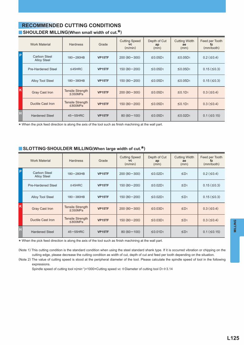
L125
Work Material Hardness Grade Cutting Speed
vc (m/min)
Depth of Cut ap
(mm)
Cutting Width ae
(mm)
Feed per Tooth fz
(mm/tooth)
P Carbon SteelAlloy Steel
180─280HB VP15TF 200 (80─300) <0.02D1 <D1 0.2 ( <0.4)
Pre-Hardened Steel <45HRC VP15TF 150 (80─200) <0.02D1 <D1 0.15 ( <0.3)
Alloy Tool Steel 180─380HB VP15TF 150 (80─200) <0.02D1 <D1 0.15 ( <0.3)
K Gray Cast Iron Tensile Strength
<350MPa VP15TF 200 (80─300) <0.03D1 <D1 0.3 ( <0.4)
Ductile Cast Iron Tensile Strength <800MPa VP15TF 150 (80─200) <0.03D1 <D1 0.3 ( <0.4)
H Hardened Steel 45─55HRC VP15TF 80 (60─100) <0.01D1 <D1 0.1 ( <0.15)
y
y
Work Material Hardness Grade Cutting Speed
vc (m/min)
Depth of Cut ap
(mm)
Cutting Width ae
(mm)
Feed per Tooth fz
(mm/tooth)
P Carbon SteelAlloy Steel
180─280HB VP15TF 200 (80─300) <0.05D1 <0.05D1 0.2 ( <0.4)
Pre-Hardened Steel <45HRC VP15TF 150 (80─200) <0.05D1 <0.05D1 0.15 ( <0.3)
Alloy Tool Steel 180─380HB VP15TF 150 (80─200) <0.05D1 <0.05D1 0.15 ( <0.3)
K Gray Cast Iron Tensile Strength
<350MPa VP15TF 200 (80─300) <0.05D1 <0.1D1 0.3 ( <0.4)
Ductile Cast Iron Tensile Strength <800MPa VP15TF 150 (80─200) <0.05D1 <0.1D1 0.3 ( <0.4)
H Hardened Steel 45─55HRC VP15TF 80 (60─100) <0.05D1 <0.02D1 0.1 ( <0.15)
MIL
LIN
G
RECOMMENDED CUTTING CONDITIONSSHOULDER MILLING(When small width of cut.*)
SLOTTING・SHOULDER MILLING(When large width of cut.*)
* When the pick feed direction is along the axis of the tool such as fi nish machining at the wall part.
* When the pick feed direction is along the axis of the tool such as fi nish machining at the wall part.
(Note 1) This cutting condition is the standard condition when using the steel standard shank type. If it is occurred vibration or chipping on the cutting edge, please decrease the cutting condition as width of cut, depth of cut and feed per tooth depending on the situation.
(Note 2) The value of cutting speed is stood at the peripheral diameter of the tool. Please calculate the spindle speed of tool in the following expressions.
Spindle speed of cutting tool n(min-1)=1000×Cutting speed vc uDiameter of cutting tool D1u3.14
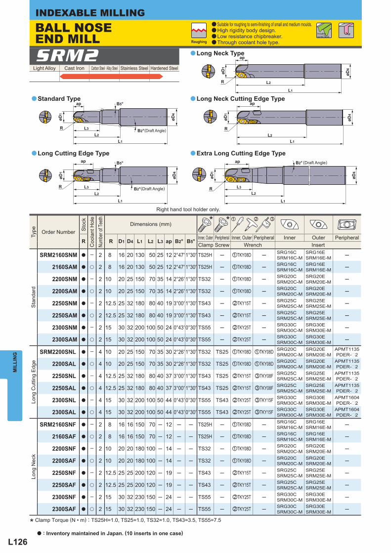
L126
R
ap
L1
L2
L3
øD1
øD4
B5°
B2°
øD1
øD4
R
ap
L1
L2
L3
B5°
B2°
R
ap
øD4
øD1
L2
L1
R
ap
øD1
øD4
L1
L2
R
ap
L1
L2
L3
øD1
øD4
B2°
Light Alloy Cast Iron Carbon Steel · Alloy Steel Stainless Steel Hardened Steel SRM2
Type
Order Number
Sto
ck
Coo
lant
Hol
e
Numb
er of
Tee
th
Dimensions (mm) * * z x c
R R D1 D4 L1 L2 L3 ap B2° B5° Inner, Outer Peripheral Inner, Outer Peripheral Inner Outer Peripheral Clamp Screw Wrench Insert
Sta
ndar
d
SRM2160SNM a ─ 2 8 16 20 130 50 25 12 2°47′ 1°30′ TS25H ─ zTKY08D ─ SRG16CSRM16C-M
SRG16ESRM16E-M ─
2160SAM a u 2 8 16 20 130 50 25 12 2°47′ 1°30′ TS25H ─ zTKY08D ─ SRG16CSRM16C-M
SRG16ESRM16E-M ─
2200SNM a ─ 2 10 20 25 150 70 35 14 2°26′ 1°30′ TS32 ─ zTKY08D ─ SRG20CSRM20C-M
SRG20ESRM20E-M ─
2200SAM a u 2 10 20 25 150 70 35 14 2°26′ 1°30′ TS32 ─ zTKY08D ─ SRG20CSRM20C-M
SRG20ESRM20E-M ─
2250SNM a ─ 2 12.5 25 32 180 80 40 19 3°00′ 1°30′ TS43 ─ xTKY15T ─ SRG25CSRM25C-M
SRG25ESRM25E-M ─
2250SAM a u 2 12.5 25 32 180 80 40 19 3°00′ 1°30′ TS43 ─ xTKY15T ─ SRG25CSRM25C-M
SRG25ESRM25E-M ─
2300SNM a ─ 2 15 30 32 200 100 50 24 0°43′ 0°30′ TS55 ─ xTKY25T ─ SRG30CSRM30C-M
SRG30ESRM30E-M ─
2300SAM a u 2 15 30 32 200 100 50 24 0°43′ 0°30′ TS55 ─ xTKY25T ─ SRG30CSRM30C-M
SRG30ESRM30E-M ─
Long
Cut
ting
Edg
e
SRM2200SNL a ─ 4 10 20 25 150 70 35 30 2°26′ 1°30′ TS32 TS25 zTKY08D zTKY08D SRG20C
SRM20C-MSRG20ESRM20E-M
APMT1135PDER-p2
2200SAL a u 4 10 20 25 150 70 35 30 2°26′ 1°30′ TS32 TS25 zTKY08D zTKY08D SRG20CSRM20C-M
SRG20ESRM20E-M
APMT1135PDER-p2
2250SNL a ─ 4 12.5 25 32 180 80 40 37 3°00′ 1°30′ TS43 TS25 xTKY15T cTKY08F SRG25CSRM25C-M
SRG25ESRM25E-M
APMT1135PDER-p2
2250SAL a u 4 12.5 25 32 180 80 40 37 3°00′ 1°30′ TS43 TS25 xTKY15T cTKY08F SRG25CSRM25C-M
SRG25ESRM25E-M
APMT1135PDER-p2
2300SNL a ─ 4 15 30 32 200 100 50 44 0°43′ 0°30′ TS55 TS43 xTKY25T cTKY15F SRG30CSRM30C-M
SRG30ESRM30E-M
APMT1604PDER-p2
2300SAL a u 4 15 30 32 200 100 50 44 0°43′ 0°30′ TS55 TS43 xTKY25T cTKY15F SRG30CSRM30C-M
SRG30ESRM30E-M
APMT1604PDER-p2
Long
Nec
k
SRM2160SNF a ─ 2 8 16 16 150 70 ─ 12 ─ ─ TS25H ─ zTKY08D ─ SRG16CSRM16C-M
SRG16ESRM16E-M ─
2160SAF a u 2 8 16 16 150 70 ─ 12 ─ ─ TS25H ─ zTKY08D ─ SRG16CSRM16C-M
SRG16ESRM16E-M ─
2200SNF a ─ 2 10 20 20 180 100 ─ 14 ─ ─ TS32 ─ zTKY08D ─ SRG20CSRM20C-M
SRG20ESRM20E-M ─
2200SAF a u 2 10 20 20 180 100 ─ 14 ─ ─ TS32 ─ zTKY08D ─ SRG20CSRM20C-M
SRG20ESRM20E-M ─
2250SNF a ─ 2 12.5 25 25 200 120 ─ 19 ─ ─ TS43 ─ xTKY15T ─ SRG25CSRM25C-M
SRG25ESRM25E-M ─
2250SAF a u 2 12.5 25 25 200 120 ─ 19 ─ ─ TS43 ─ xTKY15T ─ SRG25CSRM25C-M
SRG25ESRM25E-M ─
2300SNF a ─ 2 15 30 32 230 150 ─ 24 ─ ─ TS55 ─ xTKY25T ─ SRG30CSRM30C-M
SRG30ESRM30E-M ─
2300SAF a u 2 15 30 32 230 150 ─ 24 ─ ─ TS55 ─ xTKY25T ─ SRG30CSRM30C-M
SRG30ESRM30E-M ─
a
a
aa
a
MIL
LIN
GINDEXABLE MILLING
Long Neck Type
Long Neck Cutting Edge Type
Extra Long Cutting Edge TypeLong Cutting Edge Type
Standard Type
* Clamp Torque (N • m) : TS25H=1.0, TS25=1.0, TS32=1.0, TS43=3.5, TS55=7.5
(Draft Angle)
Roughing
Right hand tool holder only.
BALL NOSE END MILL
a Suitable for roughing to semi-fi nishing of small and medium moulds.a High rigidity body design.a Low resistance chipbreaker. a Through coolant hole type.
Including curved faces
(Draft Angle)
(Draft Angle)
a : Inventory maintained in Japan. (10 inserts in one case)
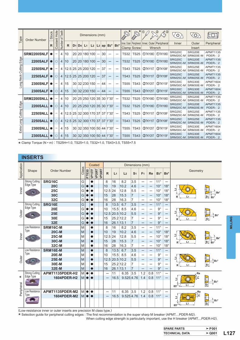
L127
L1
L1
S1
S1
Re
Re
L2L2
F1F1
85°
B3°
B3°85°
L1 S1
L1 S1
L2L2
R
B3°
B3°
R
L1R S1
L2
B3°
L1R S1
L2
B3°B9°
B9°
Type
Order Number
Sto
ck
Coo
lant
Hol
e
Numb
er of
Tee
th
Dimensions (mm) * * z x c
R R D1 D4 L1 L2 L3 ap B2° B5° Inner, Outer Peripheral Inner, Outer Peripheral Inner Outer Peripheral Clamp Screw Wrench Insert
Long
Nec
k Cu
tting
Edg
e
SRM2200SNLF a ─ 4 10 20 20 180 100 ─ 30 ─ ─ TS32 TS25 zTKY08D zTKY08D SRG20CSRM20C-M
SRG20ESRM20E-M
APMT1135PDER-p2
2200SALF a u 4 10 20 20 180 100 ─ 30 ─ ─ TS32 TS25 zTKY08D zTKY08D SRG20CSRM20C-M
SRG20ESRM20E-M
APMT1135PDER-p2
2250SNLF a ─ 4 12.5 25 25 200 120 ─ 37 ─ ─ TS43 TS25 xTKY15T cTKY08F SRG25CSRM25C-M
SRG25ESRM25E-M
APMT1135PDER-p2
2250SALF a u 4 12.5 25 25 200 120 ─ 37 ─ ─ TS43 TS25 xTKY15T cTKY08F SRG25CSRM25C-M
SRG25ESRM25E-M
APMT1135PDER-p2
2300SNLF a ─ 4 15 30 32 230 150 ─ 44 ─ ─ TS55 TS43 xTKY25T cTKY15F SRG30CSRM30C-M
SRG30ESRM30E-M
APMT1604PDER-p2
2300SALF a u 4 15 30 32 230 150 ─ 44 ─ ─ TS55 TS43 xTKY25T cTKY15F SRG30CSRM30C-M
SRG30ESRM30E-M
APMT1604PDER-p2
Extra
Lon
g Cu
tting
Edg
e
SRM2200SNLL a ─ 4 10 20 25 250 120 35 30 1°30′ ─ TS32 TS25 zTKY08D zTKY08D SRG20CSRM20C-M
SRG20ESRM20E-M
APMT1135PDER-p2
2200SALL a u 4 10 20 25 250 120 35 30 1°30′ ─ TS32 TS25 zTKY08D zTKY08D SRG20CSRM20C-M
SRG20ESRM20E-M
APMT1135PDER-p2
2250SNLL a ─ 4 12.5 25 32 300 170 37 37 1°30′ ─ TS43 TS25 xTKY15T cTKY08F SRG25CSRM25C-M
SRG25ESRM25E-M
APMT1135PDER-p2
2250SALL a u 4 12.5 25 32 300 170 37 37 1°30′ ─ TS43 TS25 xTKY15T cTKY08F SRG25CSRM25C-M
SRG25ESRM25E-M
APMT1135PDER-p2
2300SNLL a ─ 4 15 30 32 350 100 50 44 1°30′ ─ TS55 TS43 cTKY25T cTKY15F SRG30CSRM30C-M
SRG30ESRM30E-M
APMT1604PDER-p2
2300SALL a u 4 15 30 32 350 100 50 44 1°30′ ─ TS55 TS43 cTKY25T cTKY15F SRG30CSRM30C-M
SRG30ESRM30E-M
APMT1604PDER-p2
Appl
icat
ion
Shape Order Number
Cla
ss
Coated Dimensions (mm)
Geometry
F703
0VP
15TF
VP20
RTVP
30RT
R L1 L2 S1 F1 Re B3° B9°
Inne
r
Strong Cutting Edge Type
SRG16C G a 8 16 8.2 3.5 ─ ─ 11° ─20C G a a 10 19 10.2 4.6 ─ ─ 10° 18°25C G a a 12.5 24 12.8 5.5 ─ ─ 10° 18°30C G a a 15 28 15.3 7 ─ ─ 10° 18°32C G a a 16 28 16.3 7 ─ ─ 10° 18°
Out
er
Strong Cutting Edge Type
SRG16E G a 8 13.5 6.7 3.5 ─ ─ 11° ─20E G a a 10 15.5 8.5 4.6 ─ ─ 9° ─25E G a a 12.5 20.5 10.2 5.5 ─ ─ 9° ─30E G a a 15 25.2 12.2 7 ─ ─ 9° ─32E G a a 16 26.1 13.1 7 ─ ─ 9° ─
Inne
r
Low Resistance Type
SRM16C-M M a 8 16 8.2 3.5 ─ ─ 11° ─20C-M M a 10 19 10.2 4.6 ─ ─ 10° 18°25C-M M a 12.5 24 12.8 5.5 ─ ─ 10° 18°30C-M M a 15 28 15.3 7 ─ ─ 10° 18°32C-M M a 16 28 16.3 7 ─ ─ 10° 18°
Out
er
Low Resistance Type
SRM16E-M M a 8 13.5 6.7 3.5 ─ ─ 11° ─20E-M M a 10 15.5 8.5 4.6 ─ ─ 9° ─25E-M M a 12.5 20.5 10.2 5.5 ─ ─ 9° ─30E-M M a 15 25.2 12.2 7 ─ ─ 9° ─32E-M M a 16 26.1 13.1 7 ─ ─ 9° ─
*
Perip
hera
l
Strong Cutting Edge Type
APMT1135PDER-H2 M a a ─ 11 6.35 3.5 1.2 0.8 11° ─1604PDER-H2 M a a ─ 16.5 9.525 4.76 1.4 0.8 11° ─
Low Resistance Type
APMT1135PDER-M2 M a a ─ 11 6.35 3.5 1.2 0.8 11° ─1604PDER-M2 M a a ─ 16.5 9.525 4.76 1.4 0.8 11° ─
SPARE PARTS P001 TECHNICAL DATA Q001
MIL
LIN
G
INSERTS
* Clamp Torque (N • m) : TS25H=1.0, TS25=1.0, TS32=1.0, TS43=3.5, TS55=7.5
(Low-resistance inner or outer inserts are precision M class type.)
* Selection guide for peripheral cutting edges : The fi rst recommendation is the super sharp M breaker (APMT....PDER-M2). When cutting edge strength is particularly important, use the H breaker (APMT....PDER-H2).
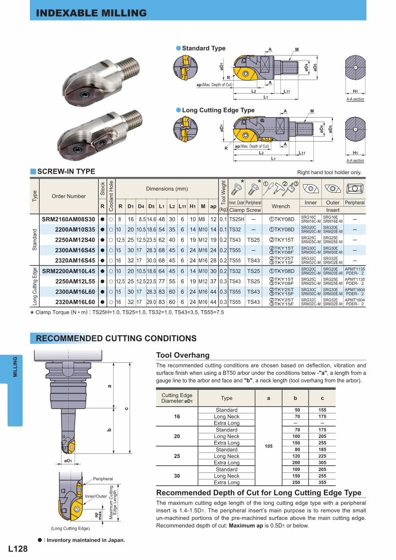
L128
øD4
øD5
M
R
L2L1
H1
ap
øD1
A
A
øD4
øD5
M
RL2
L1
apH1
A
A
øD1
L11
L11
ab
c
øD1
Type
Order Number
Sto
ck
Coo
lant
Hol
e
Dimensions (mm)
Tool
Wei
ght
(kg)
* * z x c
R R D1 D4 D5 L1 L2 L11 H1 M ap Inner, Outer Peripheral
Wrench Inner Outer Peripheral
Clamp Screw Insert
Sta
ndar
d
SRM2160AM08S30 a u 8 16 8.5 14.6 48 30 6 10 M8 12 0.1 TS25H ─ zTKY08D SRG16CSRM16C-M
SRG16ESRM16E-M ─
2200AM10S35 a u 10 20 10.5 18.6 54 35 6 14 M10 14 0.1 TS32 ─ zTKY08D SRG20CSRM20C-M
SRG20ESRM20E-M ─
2250AM12S40 a u 12.5 25 12.5 23.5 62 40 6 19 M12 19 0.2 TS43 TS25 xTKY15T SRG25CSRM25C-M
SRG25ESRM25E-M ─
2300AM16S45 a u 15 30 17 28.3 68 45 6 24 M16 24 0.2 TS55 ─ xTKY15TcTKY08F
SRG30CSRM30C-M
SRG30ESRM30E-M ─
2320AM16S45 a u 16 32 17 30.0 68 45 6 24 M16 28 0.2 TS55 TS43 xTKY25TcTKY15F
SRG32CSRM32C-M
SRG32ESRM32E-M ─
Long
Cut
ting
Edge
SRM2200AM10L45 a u 10 20 10.5 18.6 64 45 6 14 M10 30 0.2 TS32 TS25 zTKY08D SRG20CSRM20C-M
SRG20ESRM20E-M
APMT1135PDER-p2
2250AM12L55 a u 12.5 25 12.5 23.5 77 55 6 19 M12 37 0.3 TS43 TS25 xTKY15TcTKY08F
SRG25CSRM25C-M
SRG25ESRM25E-M
APMT1135PDER-p2
2300AM16L60 a u 15 30 17 28.3 83 60 6 24 M16 44 0.3 TS55 TS43 xTKY25TcTKY15F
SRG30CSRM30C-M
SRG30ESRM30E-M
APMT1604PDER-p2
2320AM16L60 a u 16 32 17 29.0 83 60 6 24 M16 44 0.3 TS55 TS43 xTKY25TcTKY15F
SRG32CSRM32C-M
SRG32ESRM32E-M
APMT1604PDER-p2
Cutting EdgeDiameter:øD1
Type a b c
16 Standard
105
50 155 Long Neck 70 175 Extra Long ─ ─
20 Standard 70 175
Long Neck 100 205 Extra Long 150 255
25 Standard 80 185
Long Neck 120 225 Extra Long 200 305
30 Standard 100 205
Long Neck 150 255 Extra Long 250 355
y
a
a
MIL
LIN
GINDEXABLE MILLING
The recommended cutting conditions are chosen based on deflection, vibration and surface fi nish when using a BT50 arbor under the conditions below -"a", a length from a gauge line to the arbor end face and "b", a neck length (tool overhang from the arbor).
The maximum cutting edge length of the long cutting edge type with a peripheral insert is 1.4-1.5D1. The peripheral insert’s main purpose is to remove the small un-machined portions of the pre-machined surface above the main cutting edge. Recommended depth of cut: Maximum ap is 0.5D1 or below.
Tool Overhang
Recommended Depth of Cut for Long Cutting Edge Type
Standard Type
Long Cutting Edge Type
* Clamp Torque (N • m) : TS25H=1.0, TS25=1.0, TS32=1.0, TS43=3.5, TS55=7.5
Peripheral
Inner/Outer
(Long Cutting Edge)
Max
imum
Cut
ting
Edg
e Le
ngth
ap max
.
RECOMMENDED CUTTING CONDITIONS
(Max. Depth of Cut)
(Max. Depth of Cut)
Right hand tool holder only.
A-A section
A-A section
SCREW-IN TYPE
a : Inventory maintained in Japan.
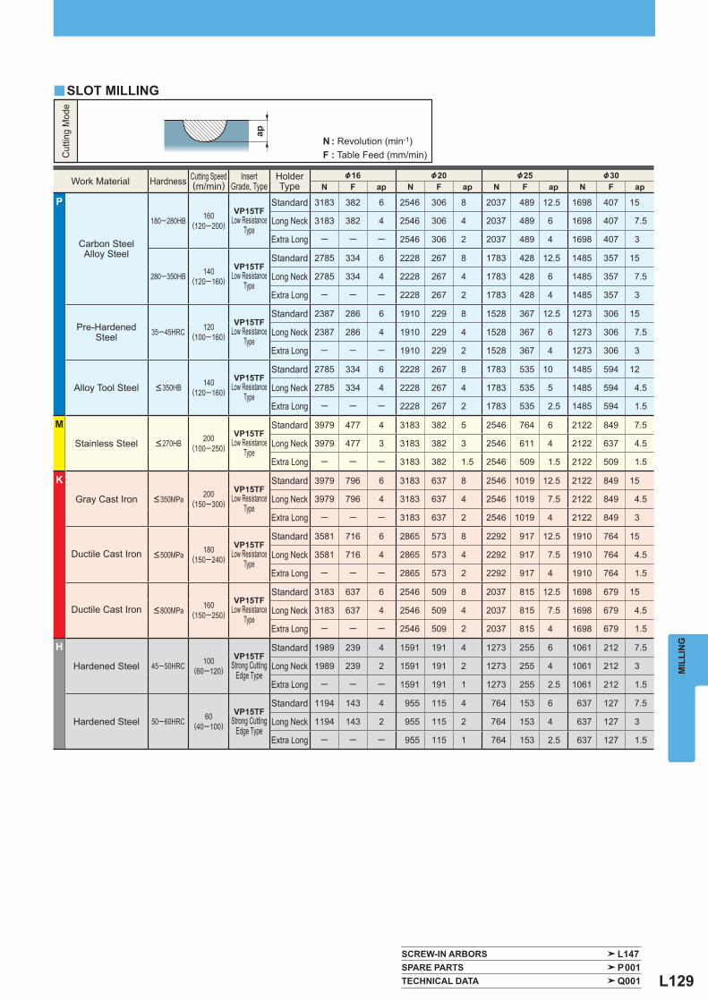
L129
ap
Work Material Hardness Cutting Speed(m/min)
InsertGrade, Type
HolderType
&16 &20 &25 &30N F ap N F ap N F ap N F ap
P
Carbon SteelAlloy Steel
180─280HB 160(120─200)
VP15TF Low Resistance
Type
Standard 3183 382 6 2546 306 8 2037 489 12.5 1698 407 15
Long Neck 3183 382 4 2546 306 4 2037 489 6 1698 407 7.5
Extra Long ─ ─ ─ 2546 306 2 2037 489 4 1698 407 3
280─350HB 140(120─160)
VP15TF Low Resistance
Type
Standard 2785 334 6 2228 267 8 1783 428 12.5 1485 357 15
Long Neck 2785 334 4 2228 267 4 1783 428 6 1485 357 7.5
Extra Long ─ ─ ─ 2228 267 2 1783 428 4 1485 357 3
Pre-Hardened Steel 35─45HRC 120
(100─160)
VP15TF Low Resistance
Type
Standard 2387 286 6 1910 229 8 1528 367 12.5 1273 306 15
Long Neck 2387 286 4 1910 229 4 1528 367 6 1273 306 7.5
Extra Long ─ ─ ─ 1910 229 2 1528 367 4 1273 306 3
Alloy Tool Steel <350HB 140(120─160)
VP15TF Low Resistance
Type
Standard 2785 334 6 2228 267 8 1783 535 10 1485 594 12
Long Neck 2785 334 4 2228 267 4 1783 535 5 1485 594 4.5
Extra Long ─ ─ ─ 2228 267 2 1783 535 2.5 1485 594 1.5
M
Stainless Steel <270HB 200(100─250)
VP15TF Low Resistance
Type
Standard 3979 477 4 3183 382 5 2546 764 6 2122 849 7.5
Long Neck 3979 477 3 3183 382 3 2546 611 4 2122 637 4.5
Extra Long ─ ─ ─ 3183 382 1.5 2546 509 1.5 2122 509 1.5
K
Gray Cast Iron <350MPa 200(150─300)
VP15TF Low Resistance
Type
Standard 3979 796 6 3183 637 8 2546 1019 12.5 2122 849 15
Long Neck 3979 796 4 3183 637 4 2546 1019 7.5 2122 849 4.5
Extra Long ─ ─ ─ 3183 637 2 2546 1019 4 2122 849 3
Ductile Cast Iron <500MPa 180(150─240)
VP15TF Low Resistance
Type
Standard 3581 716 6 2865 573 8 2292 917 12.5 1910 764 15
Long Neck 3581 716 4 2865 573 4 2292 917 7.5 1910 764 4.5
Extra Long ─ ─ ─ 2865 573 2 2292 917 4 1910 764 1.5
Ductile Cast Iron <800MPa 160(150─250)
VP15TF Low Resistance
Type
Standard 3183 637 6 2546 509 8 2037 815 12.5 1698 679 15
Long Neck 3183 637 4 2546 509 4 2037 815 7.5 1698 679 4.5
Extra Long ─ ─ ─ 2546 509 2 2037 815 4 1698 679 1.5
H
Hardened Steel 45─50HRC 100(60─120)
VP15TF Strong Cutting
Edge Type
Standard 1989 239 4 1591 191 4 1273 255 6 1061 212 7.5
Long Neck 1989 239 2 1591 191 2 1273 255 4 1061 212 3
Extra Long ─ ─ ─ 1591 191 1 1273 255 2.5 1061 212 1.5
Hardened Steel 50─60HRC 60(40─100)
VP15TF Strong Cutting
Edge Type
Standard 1194 143 4 955 115 4 764 153 6 637 127 7.5
Long Neck 1194 143 2 955 115 2 764 153 4 637 127 3
Extra Long ─ ─ ─ 955 115 1 764 153 2.5 637 127 1.5
y
SCREW-IN ARBORS L147 SPARE PARTS P001 TECHNICAL DATA Q001
MIL
LIN
G
SLOT MILLING
Cut
ting
Mod
e
N : Revolution (min-1)F : Table Feed (mm/min)
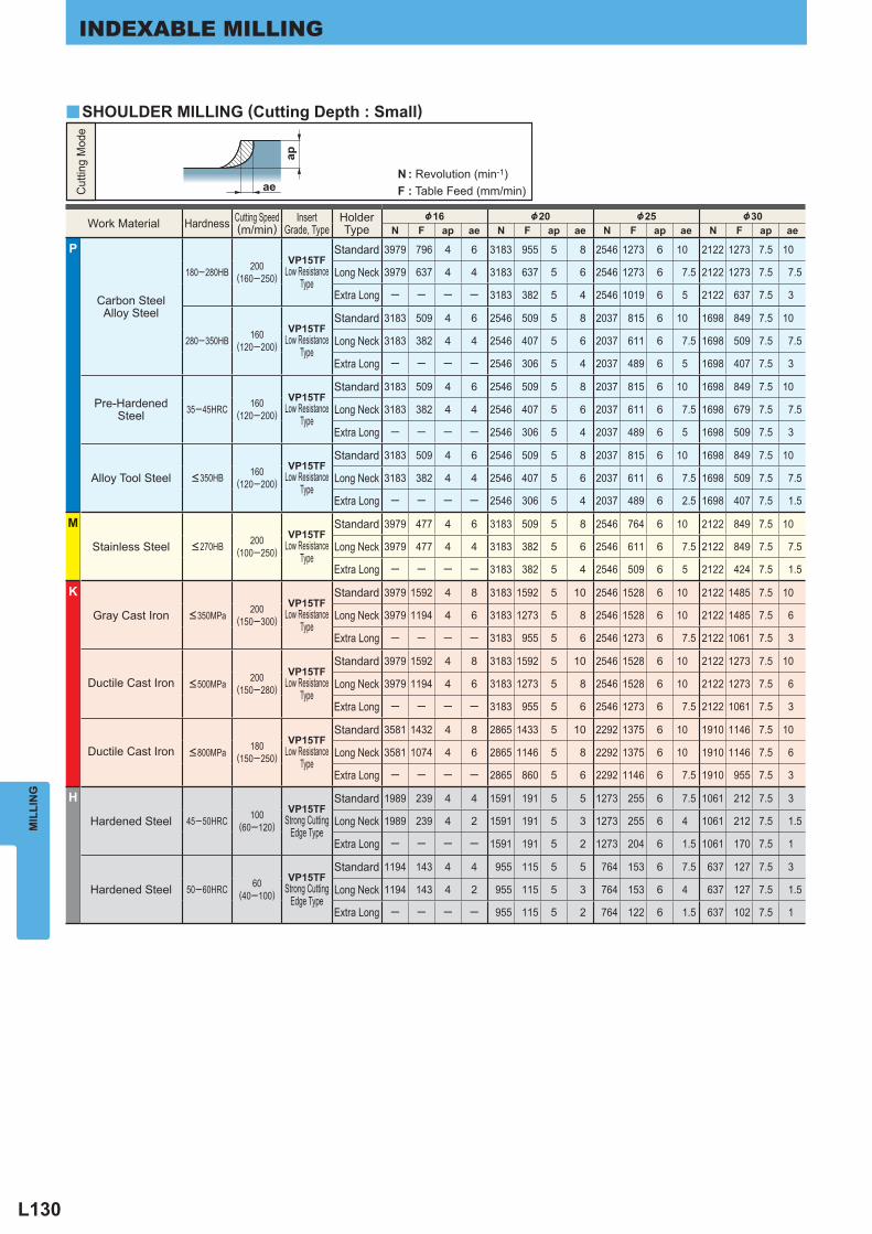
L130
ae
ap
Work Material Hardness Cutting Speed(m/min)
InsertGrade, Type
HolderType
&16 &20 &25 &30N F ap ae N F ap ae N F ap ae N F ap ae
P
Carbon SteelAlloy Steel
180─280HB 200(160─250)
VP15TF Low Resistance
Type
Standard 3979 796 4 6 3183 955 5 8 2546 1273 6 10 2122 1273 7.5 10
Long Neck 3979 637 4 4 3183 637 5 6 2546 1273 6 7.5 2122 1273 7.5 7.5
Extra Long ─ ─ ─ ─ 3183 382 5 4 2546 1019 6 5 2122 637 7.5 3
280─350HB 160(120─200)
VP15TF Low Resistance
Type
Standard 3183 509 4 6 2546 509 5 8 2037 815 6 10 1698 849 7.5 10
Long Neck 3183 382 4 4 2546 407 5 6 2037 611 6 7.5 1698 509 7.5 7.5
Extra Long ─ ─ ─ ─ 2546 306 5 4 2037 489 6 5 1698 407 7.5 3
Pre-Hardened Steel 35─45HRC 160
(120─200)
VP15TF Low Resistance
Type
Standard 3183 509 4 6 2546 509 5 8 2037 815 6 10 1698 849 7.5 10
Long Neck 3183 382 4 4 2546 407 5 6 2037 611 6 7.5 1698 679 7.5 7.5
Extra Long ─ ─ ─ ─ 2546 306 5 4 2037 489 6 5 1698 509 7.5 3
Alloy Tool Steel <350HB 160(120─200)
VP15TF Low Resistance
Type
Standard 3183 509 4 6 2546 509 5 8 2037 815 6 10 1698 849 7.5 10
Long Neck 3183 382 4 4 2546 407 5 6 2037 611 6 7.5 1698 509 7.5 7.5
Extra Long ─ ─ ─ ─ 2546 306 5 4 2037 489 6 2.5 1698 407 7.5 1.5
M
Stainless Steel <270HB 200(100─250)
VP15TF Low Resistance
Type
Standard 3979 477 4 6 3183 509 5 8 2546 764 6 10 2122 849 7.5 10
Long Neck 3979 477 4 4 3183 382 5 6 2546 611 6 7.5 2122 849 7.5 7.5
Extra Long ─ ─ ─ ─ 3183 382 5 4 2546 509 6 5 2122 424 7.5 1.5
K
Gray Cast Iron <350MPa 200(150─300)
VP15TF Low Resistance
Type
Standard 3979 1592 4 8 3183 1592 5 10 2546 1528 6 10 2122 1485 7.5 10
Long Neck 3979 1194 4 6 3183 1273 5 8 2546 1528 6 10 2122 1485 7.5 6
Extra Long ─ ─ ─ ─ 3183 955 5 6 2546 1273 6 7.5 2122 1061 7.5 3
Ductile Cast Iron <500MPa 200(150─280)
VP15TF Low Resistance
Type
Standard 3979 1592 4 8 3183 1592 5 10 2546 1528 6 10 2122 1273 7.5 10
Long Neck 3979 1194 4 6 3183 1273 5 8 2546 1528 6 10 2122 1273 7.5 6
Extra Long ─ ─ ─ ─ 3183 955 5 6 2546 1273 6 7.5 2122 1061 7.5 3
Ductile Cast Iron <800MPa 180(150─250)
VP15TF Low Resistance
Type
Standard 3581 1432 4 8 2865 1433 5 10 2292 1375 6 10 1910 1146 7.5 10
Long Neck 3581 1074 4 6 2865 1146 5 8 2292 1375 6 10 1910 1146 7.5 6
Extra Long ─ ─ ─ ─ 2865 860 5 6 2292 1146 6 7.5 1910 955 7.5 3
H
Hardened Steel 45─50HRC 100(60─120)
VP15TF Strong Cutting
Edge Type
Standard 1989 239 4 4 1591 191 5 5 1273 255 6 7.5 1061 212 7.5 3
Long Neck 1989 239 4 2 1591 191 5 3 1273 255 6 4 1061 212 7.5 1.5
Extra Long ─ ─ ─ ─ 1591 191 5 2 1273 204 6 1.5 1061 170 7.5 1
Hardened Steel 50─60HRC 60(40─100)
VP15TF Strong Cutting
Edge Type
Standard 1194 143 4 4 955 115 5 5 764 153 6 7.5 637 127 7.5 3
Long Neck 1194 143 4 2 955 115 5 3 764 153 6 4 637 127 7.5 1.5
Extra Long ─ ─ ─ ─ 955 115 5 2 764 122 6 1.5 637 102 7.5 1
y
MIL
LIN
GINDEXABLE MILLING
Cut
ting
Mod
e
N : Revolution (min-1)F : Table Feed (mm/min)
SHOULDER MILLING (Cutting Depth : Small)
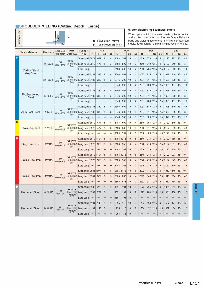
L131
ap
ae
Work Material Hardness Cutting Speed(m/min)
InsertGrade, Type
HolderType
&16 &20 &25 &30N F ap ae N F ap ae N F ap ae N F ap ae
P
Carbon SteelAlloy Steel
180─280HB 200(160─250)
VP15TF Low Resistance
Type
Standard 3979 637 8 4 3183 764 10 4 2546 1273 12.5 5 2122 1273 15 4.5
Long Neck 3979 477 8 3 3183 509 10 3 2546 1019 12.5 4 2122 849 15 3
Extra Long ─ ─ ─ ─ 3183 382 10 2 2546 764 12.5 2.5 2122 849 15 1.5
280─350HB 160(120─200)
VP15TF Low Resistance
Type
Standard 3183 382 8 4 2546 509 10 4 2037 815 12.5 5 1698 849 15 4.5
Long Neck 3183 382 8 3 2546 306 10 3 2037 611 12.5 4 1698 509 15 3
Extra Long ─ ─ ─ ─ 2546 306 10 2 2037 489 12.5 2.5 1698 407 15 1.5
Pre-Hardened Steel 35─45HRC 160
(120─200)
VP15TF Low Resistance
Type
Standard 3183 382 8 4 2546 509 10 4 2037 815 12.5 5 1698 849 15 4.5
Long Neck 3183 382 8 3 2546 306 10 3 2037 611 12.5 4 1698 509 15 3
Extra Long ─ ─ ─ ─ 2546 306 10 2 2037 489 12.5 2.5 1698 407 15 1.5
Alloy Tool Steel <350HB 160(120─200)
VP15TF Low Resistance
Type
Standard 3183 382 8 4 2546 509 10 4 2037 815 12.5 5 1698 849 15 4.5
Long Neck 3183 382 8 3 2546 306 10 3 2037 611 12.5 2.5 1698 509 15 3
Extra Long ─ ─ ─ ─ 2546 306 10 2 2037 489 12.5 1.5 1698 407 15 1.5
M
Stainless Steel <270HB 200(100─250)
VP15TF Low Resistance
Type
Standard 3979 477 8 4 3183 509 10 4 2546 764 12.5 10 2122 849 15 10
Long Neck 3979 477 8 3 3183 382 10 3 2546 611 12.5 4 2122 509 15 4.5
Extra Long ─ ─ ─ ─ 3183 382 10 2 2546 489 12.5 1.5 2122 340 15 1.5
K
Gray Cast Iron <350MPa 200(150─300)
VP15TF Low Resistance
Type
Standard 3979 1194 8 8 3183 1273 10 8 2546 1273 12.5 10 2122 1485 15 10
Long Neck 3979 955 8 5 3183 955 10 4 2546 1273 12.5 7.5 2122 1061 15 4.5
Extra Long ─ ─ ─ ─ 3183 764 10 2 2546 1019 12.5 1.5 2122 849 15 3
Ductile Cast Iron <500MPa 200(150─280)
VP15TF Low Resistance
Type
Standard 3979 1194 8 8 3183 1273 10 8 2546 1273 12.5 10 2122 1273 15 10
Long Neck 3979 955 8 5 3183 955 10 4 2546 1273 12.5 7.5 2122 849 15 4.5
Extra Long ─ ─ ─ ─ 3183 764 10 2 2546 1019 12.5 5 2122 849 15 1.5
Ductile Cast Iron <800MPa 180(150─250)
VP15TF Low Resistance
Type
Standard 3581 1074 8 8 2865 1146 10 8 2292 1146 12.5 10 1910 1146 15 10
Long Neck 3581 859 8 5 2865 860 10 4 2292 1146 12.5 7.5 1910 764 15 4.5
Extra Long ─ ─ ─ ─ 2865 688 10 2 2292 917 12.5 5 1910 764 15 1.5
H
Hardened Steel 45─50HRC 100(60─120)
VP15TF Strong Cutting
Edge Type
Standard 1989 239 8 2 1591 191 10 3 1273 255 12.5 4 1061 212 15 3
Long Neck 1989 239 8 1 1591 191 10 2 1273 204 12.5 1.5 1061 106 15 1.5
Extra Long ─ ─ ─ ─ 1591 191 10 1 ─ ─ ─ ─ ─ ─ ─ ─
Hardened Steel 50─60HRC 60(40─100)
VP15TF Strong Cutting
Edge Type
Standard 1194 143 8 2 955 115 10 3 764 153 12.5 4 637 127 15 3
Long Neck 1194 143 8 1 955 115 10 2 764 122 12.5 1.5 637 64 15 1.5
Extra Long ─ ─ ─ ─ 955 115 10 1 ─ ─ ─ ─ ─ ─ ─ ─
y
TECHNICAL DATA Q001
MIL
LIN
G
When up-cut milling stainless steels at large depths and widths of cut, the machined surface is liable to burrs and welding due to chip jamming. For stainless steels, down-cutting (climb milling) is recommended.
(Note) Machining Stainless Steels
Cut
ting
Mod
e
N : Revolution (min-1)F : Table Feed (mm/min)
SHOULDER MILLING (Cutting Depth : Large)
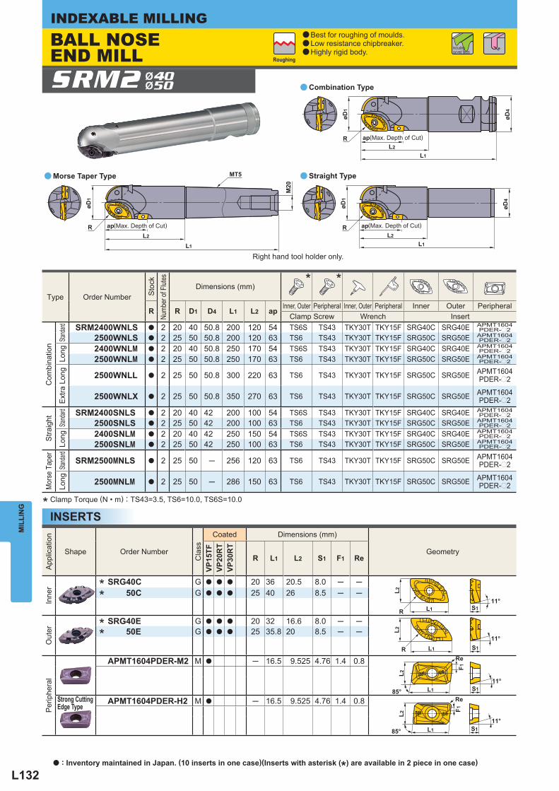
L132
L2
L1
R
MT5
M20
øD1
L2
L1
R
øD1
øD4
L2
L1
R
øD1
øD4
ap ap
ap
L1
L1
S1
S1
Re
Re
L2L2
F1F1
85°
11°
11°85°
L1 S1
L2
11°
R
L1 S1
L2
R
11°
App
licat
ion
Shape Order Number
Cla
ss
Coated Dimensions (mm)
Geometry
VP15
TFVP
20R
TVP
30R
T
R L1 L2 S1 F1 Re
Inne
r
* SRG40C G a a a 20 36 20.5 8.0 ─ ─
* 50C G a a a 25 40 26 8.5 ─ ─
Out
er
* SRG40E G a a a 20 32 16.6 8.0 ─ ─
* 50E G a a a 25 35.8 20 8.5 ─ ─
Per
iphe
ral
APMT1604PDER-M2 M a ─ 16.5 9.525 4.76 1.4 0.8
Strong Cutting Edge Type
APMT1604PDER-H2 M a ─ 16.5 9.525 4.76 1.4 0.8
SRM2 Ø40Ø50 a
aa
Type
Order Number
Sto
ck
Numb
er of
Flut
es
Dimensions (mm) * *
R R D1 D4 L1 L2 ap Inner, Outer Peripheral Inner, Outer Peripheral Inner Outer Peripheral Clamp Screw Wrench Insert
Com
bina
tion
Standa
rd
SRM2400WNLS a 2 20 40 50.8 200 120 54 TS6S TS43 TKY30T TKY15F SRG40C SRG40E APMT1604PDER-p2
2500WNLS a 2 25 50 50.8 200 120 63 TS6 TS43 TKY30T TKY15F SRG50C SRG50E APMT1604PDER-p2
Long
2400WNLM a 2 20 40 50.8 250 170 54 TS6S TS43 TKY30T TKY15F SRG40C SRG40E APMT1604PDER-p2
2500WNLM a 2 25 50 50.8 250 170 63 TS6 TS43 TKY30T TKY15F SRG50C SRG50E APMT1604PDER-p2
Ext
ra L
ong
2500WNLL a 2 25 50 50.8 300 220 63 TS6 TS43 TKY30T TKY15F SRG50C SRG50E APMT1604PDER-p2
2500WNLX a 2 25 50 50.8 350 270 63 TS6 TS43 TKY30T TKY15F SRG50C SRG50E APMT1604PDER-p2
Stra
ight
Standa
rd
SRM2400SNLS a 2 20 40 42 200 100 54 TS6S TS43 TKY30T TKY15F SRG40C SRG40E APMT1604PDER-p2
2500SNLS a 2 25 50 42 200 100 63 TS6 TS43 TKY30T TKY15F SRG50C SRG50E APMT1604PDER-p2
Long
2400SNLM a 2 20 40 42 250 150 54 TS6S TS43 TKY30T TKY15F SRG40C SRG40E APMT1604PDER-p2
2500SNLM a 2 25 50 42 250 100 63 TS6 TS43 TKY30T TKY15F SRG50C SRG50E APMT1604PDER-p2
Mor
se T
aper
Standa
rd
SRM2500MNLS a 2 25 50 ─ 256 120 63 TS6 TS43 TKY30T TKY15F SRG50C SRG50E APMT1604PDER-p2
Long
2500MNLM a 2 25 50 ─ 286 150 63 TS6 TS43 TKY30T TKY15F SRG50C SRG50E APMT1604PDER-p2
MIL
LIN
GINDEXABLE MILLING
INSERTS
Combination Type
Straight TypeMorse Taper Type
* Clamp Torque (N • m) : TS43=3.5, TS6=10.0, TS6S=10.0
Roughing
(Max. Depth of Cut)
(Max. Depth of Cut)
(Max. Depth of Cut)
Right hand tool holder only.
BALL NOSE END MILL
Including curved faces
a Best for roughing of moulds.a Low resistance chipbreaker.a Highly rigid body.
a : Inventory maintained in Japan. (10 inserts in one case)(Inserts with asterisk (*) are available in 2 piece in one case)
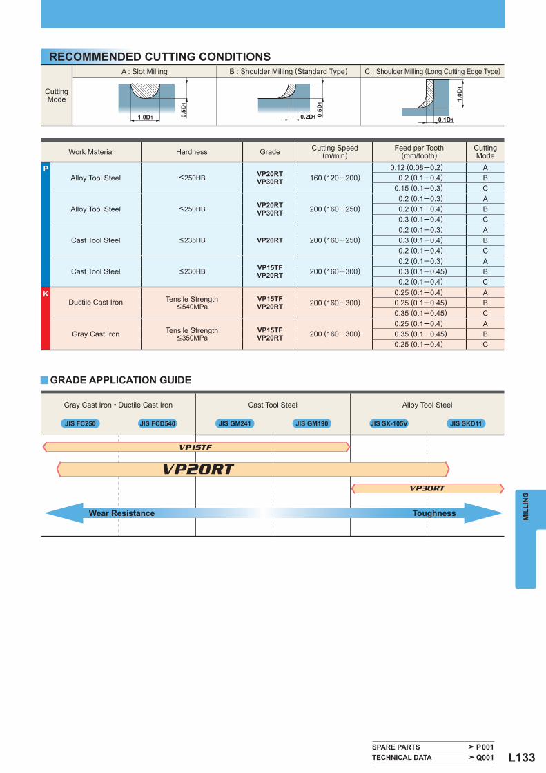
L133
1.0D1 0.5D
1
0.2D1 0.5D
1 1.0D
1
0.1D1
Gray Cast Iron • Ductile Cast Iron Cast Tool Steel Alloy Tool Steel
Work Material Hardness Grade Cutting Speed(m/min)
Feed per Tooth(mm/tooth)
CuttingMode
P Alloy Tool Steel <250HB VP20RT
VP30RT 160 (120─200)0.12 (0.08─0.2) A
0.2 (0.1─0.4) B0.15 (0.1─0.3) C
Alloy Tool Steel <250HB VP20RTVP30RT 200 (160─250)
0.2 (0.1─0.3) A0.2 (0.1─0.4) B0.3 (0.1─0.4) C
Cast Tool Steel <235HB VP20RT 200 (160─250)0.2 (0.1─0.3) A0.3 (0.1─0.4) B0.2 (0.1─0.4) C
Cast Tool Steel <230HB VP15TFVP20RT 200 (160─300)
0.2 (0.1─0.3) A0.3 (0.1─0.45) B0.2 (0.1─0.4) C
K Ductile Cast Iron Tensile Strength
<540MPaVP15TFVP20RT 200 (160─300)
0.25 (0.1─0.4) A0.25 (0.1─0.45) B0.35 (0.1─0.45) C
Gray Cast Iron Tensile Strength <350MPa
VP15TFVP20RT 200 (160─300)
0.25 (0.1─0.4) A0.35 (0.1─0.45) B0.25 (0.1─0.4) C
y
CuttingMode
A : Slot Milling B : Shoulder Milling (Standard Type) C : Shoulder Milling (Long Cutting Edge Type)
JIS FC250 JIS FCD540 JIS GM241 JIS GM190 JIS SX-105V JIS SKD11
VP15TF
VP30RT
VP20RT
SPARE PARTS P001 TECHNICAL DATA Q001
MIL
LIN
G
RECOMMENDED CUTTING CONDITIONS
GRADE APPLICATION GUIDE
ToughnessWear Resistance
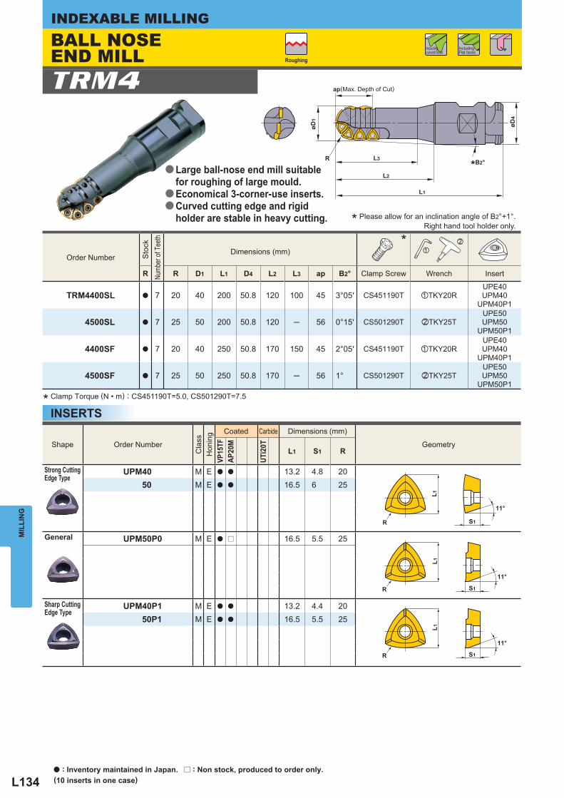
L134
øD1
R L3
L2
øD4
L1
ap
R
L1
S1
11°
R S1
11°
L1
R S1
11°
L1
R
Shape Order Number
Cla
ss
Hon
ing
Coated Carbide Dimensions (mm)
Geometry
VP15
TFAP
20M
UTi2
0T
L1 S1 R
Strong Cutting Edge Type
UPM40 M E a a 13.2 4.8 2050 M E a a 16.5 6 25
General UPM50P0 M E a r 16.5 5.5 25
Sharp Cutting Edge Type
UPM40P1 M E a a 13.2 4.4 2050P1 M E a a 16.5 5.5 25
Order Number
Sto
ck
Numb
er of
Tee
th
Dimensions (mm) *
z
x
R R D1 L1 D4 L2 L3 ap B2° Clamp Screw Wrench Insert
TRM4400SL a 7 20 40 200 50.8 120 100 45 3°05′ CS451190T zTKY20RUPE40UPM40
UPM40P1
4500SL a 7 25 50 200 50.8 120 ─ 56 0°15′ CS501290T xTKY25TUPE50UPM50
UPM50P1
4400SF a 7 20 40 250 50.8 170 150 45 2°05′ CS451190T zTKY20RUPE40UPM40
UPM40P1
4500SF a 7 25 50 250 50.8 170 ─ 56 1° CS501290T xTKY25TUPE50UPM50
UPM50P1
TRM4
MIL
LIN
GINDEXABLE MILLING
* Clamp Torque (N • m) : CS451190T=5.0, CS501290T=7.5
Including Flat faces
Including curved faces
INSERTS
Roughing
(Max. Depth of Cut)
Right hand tool holder only.
BALL NOSE END MILL
Large ball-nose end mill suitable for roughing of large mould.Economical 3-corner-use inserts.Curved cutting edge and rigid holder are stable in heavy cutting.
a
a
a
* Please allow for an inclination angle of B2°+1°.
*B2°
a : Inventory maintained in Japan. r : Non stock, produced to order only.(10 inserts in one case)
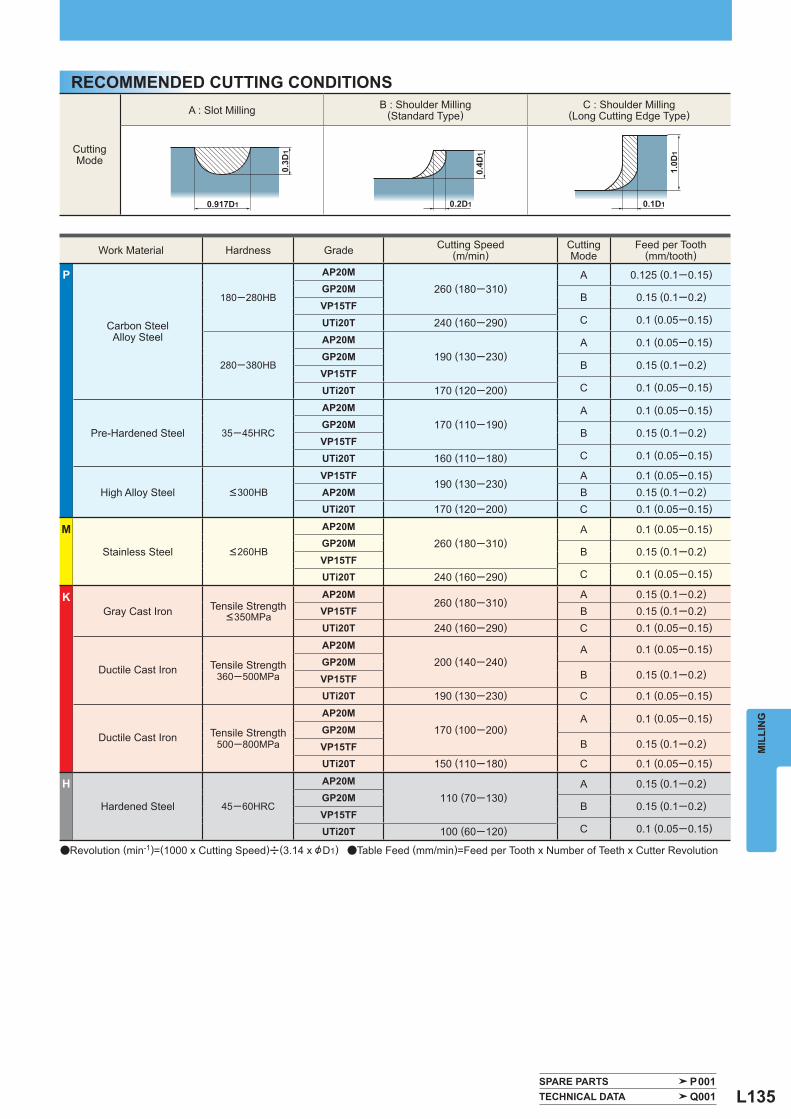
L135
0.917D1
0.3D
1
0.2D1
0.4D
1
1.0D
1
0.1D1
CuttingMode
A : Slot Milling B : Shoulder Milling (Standard Type)
C : Shoulder Milling (Long Cutting Edge Type)
Work Material Hardness Grade Cutting Speed(m/min)
CuttingMode
Feed per Tooth(mm/tooth)
P
Carbon SteelAlloy Steel
180─280HB
AP20M260 (180─310)
A 0.125 (0.1─0.15)GP20M
B 0.15 (0.1─0.2)VP15TF
C 0.1 (0.05─0.15)UTi20T 240 (160─290)
280─380HB
AP20M190 (130─230)
A 0.1 (0.05─0.15)GP20M
B 0.15 (0.1─0.2)VP15TF
C 0.1 (0.05─0.15)UTi20T 170 (120─200)
Pre-Hardened Steel 35─45HRC
AP20M170 (110─190)
A 0.1 (0.05─0.15)GP20M
B 0.15 (0.1─0.2)VP15TF
C 0.1 (0.05─0.15)UTi20T 160 (110─180)
High Alloy Steel <300HB
VP15TF190 (130─230)
A 0.1 (0.05─0.15)AP20M B 0.15 (0.1─0.2)UTi20T 170 (120─200) C 0.1 (0.05─0.15)
M
Stainless Steel <260HB
AP20M260 (180─310)
A 0.1 (0.05─0.15)GP20M
B 0.15 (0.1─0.2)VP15TF
C 0.1 (0.05─0.15)UTi20T 240 (160─290)
K Gray Cast Iron Tensile Strength
<350MPa
AP20M260 (180─310)
A 0.15 (0.1─0.2)VP15TF B 0.15 (0.1─0.2)UTi20T 240 (160─290) C 0.1 (0.05─0.15)
Ductile Cast Iron Tensile Strength 360─500MPa
AP20M200 (140─240)
A 0.1 (0.05─0.15)GP20M
B 0.15 (0.1─0.2)VP15TFUTi20T 190 (130─230) C 0.1 (0.05─0.15)
Ductile Cast Iron Tensile Strength 500─800MPa
AP20M170 (100─200)
A 0.1 (0.05─0.15)GP20M
B 0.15 (0.1─0.2)VP15TFUTi20T 150 (110─180) C 0.1 (0.05─0.15)
H
Hardened Steel 45─60HRC
AP20M110 (70─130)
A 0.15 (0.1─0.2)GP20M
B 0.15 (0.1─0.2)VP15TF
C 0.1 (0.05─0.15)UTi20T 100 (60─120)
SPARE PARTS P001 TECHNICAL DATA Q001
MIL
LIN
G
RECOMMENDED CUTTING CONDITIONS
aRevolution (min-1)=(1000 x Cutting Speed)u(3.14 x &D1) aTable Feed (mm/min)=Feed per Tooth x Number of Teeth x Cutter Revolution
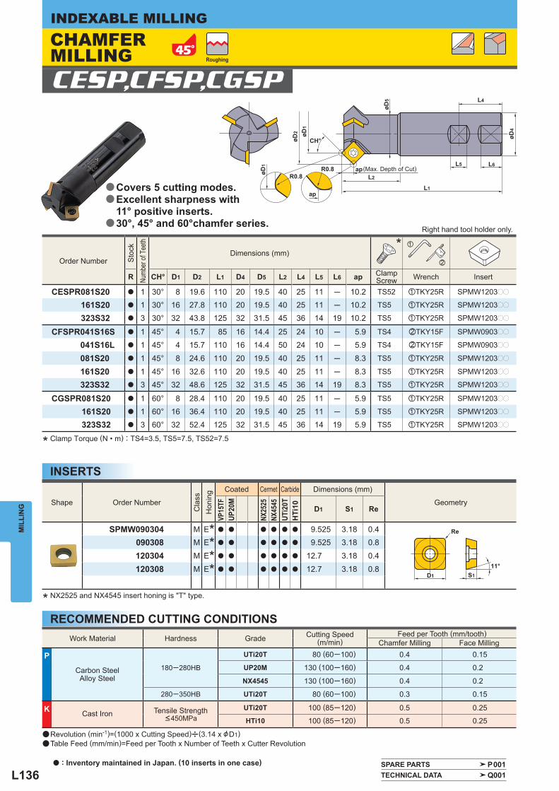
L136
L5 L6
øD4
L4
L1
L2ap
øD2 øD
1
øD5
øD1
CH°
ap
R0.8R0.8
Re
S1
11°D1
CESP,CFSP,CGSP
Order Number
Sto
ck
Numb
er of
Tee
th
Dimensions (mm) * z
x
R CH° D1 D2 L1 D4 D5 L2 L4 L5 L6 ap Clamp Screw Wrench Insert
CESPR081S20 a 1 30° 8 19.6 110 20 19.5 40 25 11 ─ 10.2 TS52 zTKY25R SPMW1203pp
161S20 a 1 30° 16 27.8 110 20 19.5 40 25 11 ─ 10.2 TS5 zTKY25R SPMW1203pp
323S32 a 3 30° 32 43.8 125 32 31.5 45 36 14 19 10.2 TS5 zTKY25R SPMW1203pp
CFSPR041S16S a 1 45° 4 15.7 85 16 14.4 25 24 10 ─ 5.9 TS4 xTKY15F SPMW0903pp
041S16L a 1 45° 4 15.7 110 16 14.4 50 24 10 ─ 5.9 TS4 xTKY15F SPMW0903pp
081S20 a 1 45° 8 24.6 110 20 19.5 40 25 11 ─ 8.3 TS5 zTKY25R SPMW1203pp
161S20 a 1 45° 16 32.6 110 20 19.5 40 25 11 ─ 8.3 TS5 zTKY25R SPMW1203pp
323S32 a 3 45° 32 48.6 125 32 31.5 45 36 14 19 8.3 TS5 zTKY25R SPMW1203pp
CGSPR081S20 a 1 60° 8 28.4 110 20 19.5 40 25 11 ─ 5.9 TS5 zTKY25R SPMW1203pp
161S20 a 1 60° 16 36.4 110 20 19.5 40 25 11 ─ 5.9 TS5 zTKY25R SPMW1203pp
323S32 a 3 60° 32 52.4 125 32 31.5 45 36 14 19 5.9 TS5 zTKY25R SPMW1203pp
Shape Order Number
Cla
ss
Hon
ing
Coated Cermet Carbide Dimensions (mm)
Geometry
VP15
TFUP
20M
NX25
25NX
4545
UTi2
0TH
Ti10 D1 S1 Re
SPMW090304 M E* a a a a a a 9.525 3.18 0.4090308 M E* a a a a a a 9.525 3.18 0.8
120304 M E* a a a a a a 12.7 3.18 0.4
120308 M E* a a a a a a 12.7 3.18 0.8
Work Material Hardness Grade Cutting Speed(m/min)
Feed per Tooth (mm/tooth) Chamfer Milling Face Milling
P
Carbon SteelAlloy Steel
180─280HB
UTi20T 80 (60─100) 0.4 0.15
UP20M 130 (100─160) 0.4 0.2
NX4545 130 (100─160) 0.4 0.2
280─350HB UTi20T 80 (60─100) 0.3 0.15
K Cast Iron Tensile Strength <450MPa
UTi20T 100 (85─120) 0.5 0.25
HTi10 100 (85─120) 0.5 0.25
SPARE PARTS P001 TECHNICAL DATA Q001
MIL
LIN
GINDEXABLE MILLING
RECOMMENDED CUTTING CONDITIONS
* Clamp Torque (N • m) : TS4=3.5, TS5=7.5, TS52=7.5
* NX2525 and NX4545 insert honing is "T" type.
INSERTS
Roughing
(Max. Depth of Cut)
Right hand tool holder only.
a Revolution (min-1)=(1000 x Cutting Speed)u(3.14 x &D1)a Table Feed (mm/min)=Feed per Tooth x Number of Teeth x Cutter Revolution
CHAMFER MILLING
Covers 5 cutting modes.Excellent sharpness with 11° positive inserts.30°, 45° and 60°chamfer series.
a
a
a
a : Inventory maintained in Japan. (10 inserts in one case)
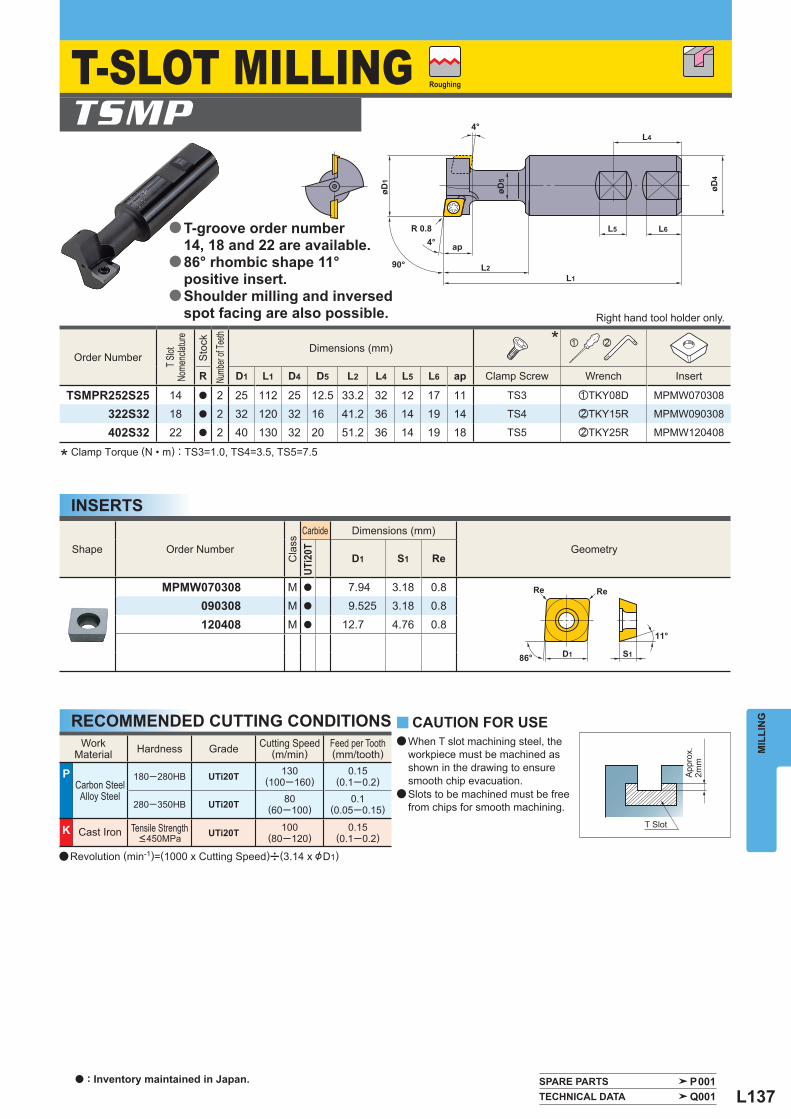
L137
øD4
L4
L6L5
L1L2
R 0.84°
4°
90°
øD1
ap
øD5
86°
Re
D1 S1
11°
Re
Shape Order Number
Cla
ss
Carbide Dimensions (mm)
Geometry
UTi2
0T
D1 S1 Re
MPMW070308 M a 7.94 3.18 0.8090308 M a 9.525 3.18 0.8
120408 M a 12.7 4.76 0.8
Order Number T Slot
No
menc
lature
Sto
ck
Numb
er of
Teeth
Dimensions (mm) * z x
R D1 L1 D4 D5 L2 L4 L5 L6 ap Clamp Screw Wrench Insert
TSMPR252S25 14 a 2 25 112 25 12.5 33.2 32 12 17 11 TS3 zTKY08D MPMW070308
322S32 18 a 2 32 120 32 16 41.2 36 14 19 14 TS4 xTKY15R MPMW090308
402S32 22 a 2 40 130 32 20 51.2 36 14 19 18 TS5 xTKY25R MPMW120408
WorkMaterial Hardness Grade Cutting Speed
(m/min) Feed per Tooth(mm/tooth)
P Carbon Steel
Alloy Steel
180─280HB UTi20T 130(100─160)
0.15(0.1─0.2)
280─350HB UTi20T 80(60─100)
0.1 (0.05─0.15)
K Cast Iron Tensile Strength <450MPa UTi20T 100
(80─120)0.15
(0.1─0.2)
TSMP
y
SPARE PARTS P001 TECHNICAL DATA Q001
MIL
LIN
G
* Clamp Torque (N • m) : TS3=1.0, TS4=3.5, TS5=7.5
CAUTION FOR USE
T Slot
App
rox.
2mm
RECOMMENDED CUTTING CONDITIONS
INSERTS
Roughing
Right hand tool holder only.
a Revolution (min-1)=(1000 x Cutting Speed)u(3.14 x &D1)
T-SLOT MILLING
T-groove order number 14, 18 and 22 are available.86° rhombic shape 11° positive insert.Shoulder milling and inversed spot facing are also possible.
a
a
a
a When T slot machining steel, the workpiece must be machined as shown in the drawing to ensure smooth chip evacuation.
a Slots to be machined must be free from chips for smooth machining.
a : Inventory maintained in Japan.
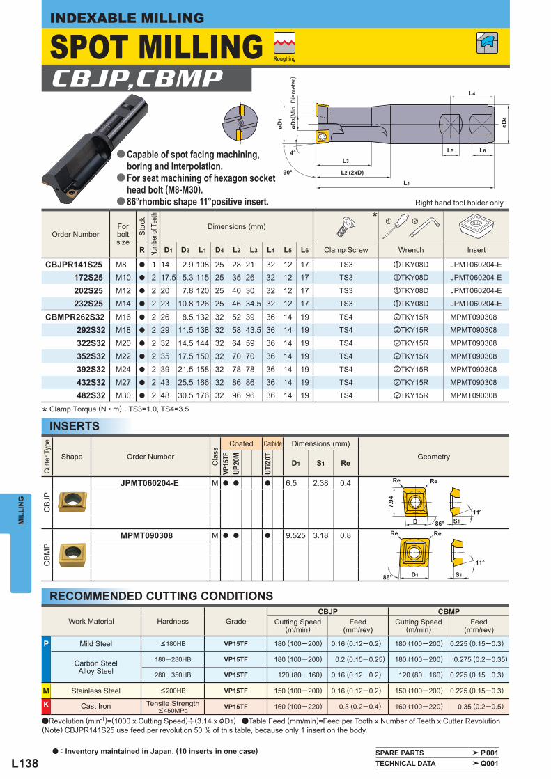
L138
Re
D1 S1
11°
86°
Re
7.94
øD4
L1
L2 (2xD)90°
4°L3
øD3
øD1
L6L5
L4
86°
Re
D1 S1
11°
Re
Cutte
r Typ
e
Shape Order Number
Cla
ss
Coated Carbide Dimensions (mm)
Geometry
VP15
TFUP
20M
UTi2
0T
D1 S1 Re
CB
JP
JPMT060204-E M a a a 6.5 2.38 0.4
CB
MP
MPMT090308 M a a a 9.525 3.18 0.8
Work Material Hardness Grade CBJP CBMP
Cutting Speed (m/min)
Feed(mm/rev)
Cutting Speed (m/min)
Feed(mm/rev)
P Mild Steel <180HB VP15TF 180 (100─200) 0.16 (0.12─0.2) 180 (100─200) 0.225 (0.15─0.3)
Carbon SteelAlloy Steel
180─280HB VP15TF 180 (100─200) 0.2 (0.15─0.25) 180 (100─200) 0.275 (0.2─0.35)
280─350HB VP15TF 120 (80─160) 0.16 (0.12─0.2) 120 (80─160) 0.225 (0.15─0.3)
M Stainless Steel <200HB VP15TF 150 (100─200) 0.16 (0.12─0.2) 150 (100─200) 0.225 (0.15─0.3)
K Cast Iron Tensile Strength <450MPa VP15TF 160 (100─220) 0.3 (0.2─0.4) 160 (100─220) 0.35 (0.2─0.5)
Order Number Forboltsize
Sto
ck
Numb
er of
Tee
th
Dimensions (mm) * z x
R D1 D3 L1 D4 L2 L3 L4 L5 L6 Clamp Screw Wrench Insert
CBJPR141S25 M8 a 1 14 2.9 108 25 28 21 32 12 17 TS3 zTKY08D JPMT060204-E
172S25 M10 a 2 17.5 5.3 115 25 35 26 32 12 17 TS3 zTKY08D JPMT060204-E
202S25 M12 a 2 20 7.8 120 25 40 30 32 12 17 TS3 zTKY08D JPMT060204-E
232S25 M14 a 2 23 10.8 126 25 46 34.5 32 12 17 TS3 zTKY08D JPMT060204-E
CBMPR262S32 M16 a 2 26 8.5 132 32 52 39 36 14 19 TS4 xTKY15R MPMT090308
292S32 M18 a 2 29 11.5 138 32 58 43.5 36 14 19 TS4 xTKY15R MPMT090308
322S32 M20 a 2 32 14.5 144 32 64 59 36 14 19 TS4 xTKY15R MPMT090308
352S32 M22 a 2 35 17.5 150 32 70 70 36 14 19 TS4 xTKY15R MPMT090308
392S32 M24 a 2 39 21.5 158 32 78 78 36 14 19 TS4 xTKY15R MPMT090308
432S32 M27 a 2 43 25.5 166 32 86 86 36 14 19 TS4 xTKY15R MPMT090308
482S32 M30 a 2 48 30.5 176 32 96 96 36 14 19 TS4 xTKY15R MPMT090308
CBJP,CBMP
SPARE PARTS P001 TECHNICAL DATA Q001
MIL
LIN
GINDEXABLE MILLING
INSERTS
RECOMMENDED CUTTING CONDITIONS
* Clamp Torque (N • m) : TS3=1.0, TS4=3.5
( Min
. Dia
met
er)
Roughing
Right hand tool holder only.
SPOT MILLING
Capable of spot facing machining, boring and interpolation.For seat machining of hexagon sockethead bolt (M8-M30).86°rhombic shape 11°positive insert.
a
a
a
aRevolution (min-1)=(1000 x Cutting Speed)u(3.14 x &D1) aTable Feed (mm/min)=Feed per Tooth x Number of Teeth x Cutter Revolution(Note) CBJPR141S25 use feed per revolution 50 % of this table, because only 1 insert on the body.
a : Inventory maintained in Japan. (10 inserts in one case)
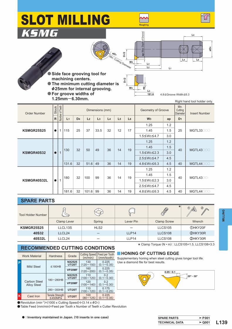
L139
D1/
2
øD1
W3
W3 ap
L3181.6
L4
L5 L6
øD4
L3L2 L1
apD1/
2
SPARE PARTS P001 TECHNICAL DATA Q001
Order Number
Sto
ck
Numb
er of
Teeth
Dimensions (mm) Geometry of Groove Min.
CuttingDiameter Insert Number
R L1 D4 L2 L3 L4 L5 L6 W3 ap D1
KSMGR25S25 a 1 115 25 37 33.5 32 12 171.25 1.2
25 MGTL33ppp1.45 1.51.5 <W3 <4.7 3.0
KSMGR40S32 a 1130 32 50 49 36 14 19
1.25 1.2
40 MGTL43ppp1.45 1.5
1.5 <W3 <2.3 3.0
2.5 <W3 <4.7 4.5131.6 32 51.6 49 36 14 19 4.8 <W3 <6.3 4.5 40 MGTL44ppp
KSMGR40S32L a 1180 32 100 99 36 14 19
1.25 1.2
40 MGTL43pp1.45 1.5
1.5 <W3 <2.3 3.0
2.5 <W3 <4.7 4.5181.6 32 101.6 99 36 14 19 4.8 <W3 <6.3 4.5 40 MGTL44ppp
Tool Holder Number
* z x
Clamp Lever Spring Lever Pin Clamp Screw Wrench
KSMGR25S25 LLCL13S HLS2 ─ LLCS105 zHKY20F40S32 LLCL24 ─ LLP14 LLCS108 xHKY30R40S32L LLCL24 ─ LLP14 LLCS108 xHKY30R
Work Material Hardness Grade Cutting Speed (m/min)
Feed per Tooth(mm/tooth)
P Mild Steel <180HB
NX2525UTi20T
130(120─150)
0.225(0.1─0.35)
VP20MF 160(120─200)
0.225(0.1─0.35)
Carbon SteelAlloy Steel
180─280HB
NX2525UTi20T
110(100─120)
0.2(0.1─0.30)
VP20MF 120(100─140)
0.2(0.1─0.30)
280─350HB UTi20T 110(100─120)
0.175(0.1─0.25)
K Cast Iron Tensile Strength <450MPa UTi20T 100
(80─125)0.225
(0.1─0.35)
KSMG
y
MIL
LIN
G
RECOMMENDED CUTTING CONDITIONS
SPARE PARTS
Supplementary honing when steel cutting gives longer tool life. Use a diamond fi le for best results.
4.8<Groove Width<6.3
* Clamp Torque (N • m) : LLCS105=1.5, LLCS108=3.3
HONING OF CUTTING EDGE
( Max
. Dep
th o
f Gro
ove)
Roughing
Right hand tool holder only.
a Revolution (min-1)=(1000 x Cutting Speed)u(3.14 x &D1)a Table Feed (mm/min)=Feed per Tooth x Number of Teeth x Cutter Revolution
SLOT MILLING
Side face grooving tool for machining centers.The minimum cutting diameter is &25mm for internal grooving.For groove widths of 1.25mm─6.30mm.
a
a
a
Min. Cutting Diameter
a : Inventory maintained in Japan. (10 inserts in one case)
L140
D1
Re
S1
W3
±0.0
25L3
Order Number Grooving
Width
Stock Dimensions (mm)
Geometry
Coated Cermet Carbide
D1 S1 Re L3
VP20
MF
NX2
525
NX5
5
UTi
20T
W3 L L L LMGTL33125 1.25 a a 9.525 4.76 0.2 1.2 MGTL...
33145 1.45 a a 9.525 4.76 0.2 1.5
33150 1.5 a a [ a 9.525 4.76 0.2 3
33175 1.75 a a a 9.525 4.76 0.2 3
33200 2 a a [ a 9.525 4.76 0.2 3
33230 2.3 a a 9.525 4.76 0.2 3
33250 2.5 a a [ a 9.525 4.76 0.3 3
33270 2.7 a a 9.525 4.76 0.3 3
33280 2.8 a a 9.525 4.76 0.3 3
33300 3 a r [ a 9.525 4.76 0.3 3
33320 3.2 a 9.525 4.76 0.3 3
33330 3.3 a a 9.525 4.76 0.3 3
33350 3.5 a a 9.525 4.76 0.3 3
33400 4 a a a 9.525 4.76 0.3 333470 4.7 r r 9.525 4.76 0.4 3
MGTL43125 1.25 a a [ a 12.7 4.76 0.2 1.243145 1.45 a a a 12.7 4.76 0.2 1.5
43150 1.5 a a [ a 12.7 4.76 0.2 3
43175 1.75 a a a 12.7 4.76 0.2 3
43200 2 a a [ a 12.7 4.76 0.2 3
43230 2.3 a a [ a 12.7 4.76 0.2 3
43250 2.5 a a [ a 12.7 4.76 0.3 4.5
43260 2.6 a a 12.7 4.76 0.3 4.5
43270 2.7 a a 12.7 4.76 0.3 4.5
43280 2.8 a a [ a 12.7 4.76 0.3 4.5
43300 3 a a [ a 12.7 4.76 0.3 4.5
43320 3.2 a [ a 12.7 4.76 0.3 4.5
43330 3.3 a a [ a 12.7 4.76 0.3 4.5
43350 3.5 a a [ a 12.7 4.76 0.3 4.5
43400 4 a [ a 12.7 4.76 0.3 4.5
43420 4.2 a a 12.7 4.76 0.4 4.5
43430 4.3 a [ a 12.7 4.76 0.4 4.5
43450 4.5 a a [ a 12.7 4.76 0.4 4.543470 4.7 a a a 12.7 4.76 0.4 4.5
MGTL44500 5 a a 12.7 6.35 0.4 4.544550 5.5 r r 12.7 6.35 0.4 4.544600 6 r a 12.7 6.35 0.4 4.5
SPARE PARTS P001 TECHNICAL DATA Q001
MIL
LIN
GINDEXABLE MILLING
INSERTS
a : Inventory maintained in Japan. r : Non stock, produced to order only.[ : Inventory maintained in Japan. To be replaced by new products.(10 inserts in one case)
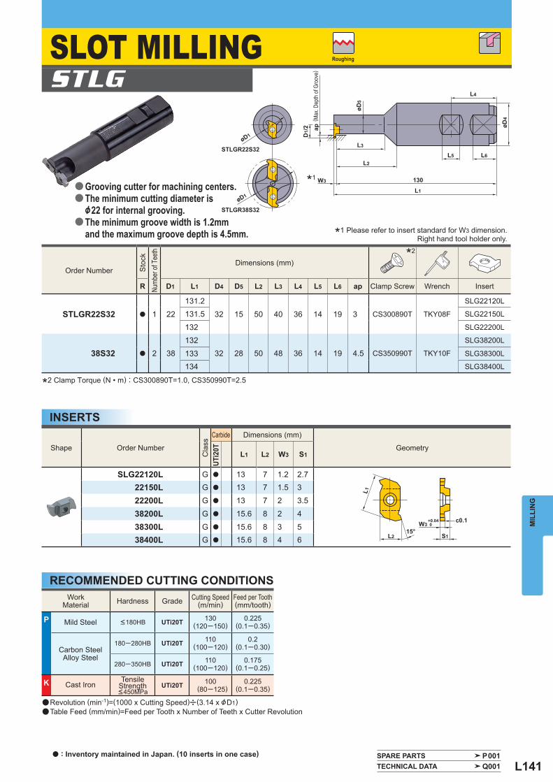
L141
L1
L2 S115°
c0.1W3+0.040
øD1 D1/
2 ap
øD5
L2
W3
L3
STLGR38S32
STLGR22S32
130
L1
øD4
L4
L6L5
øD1
Shape Order Number
Cla
ss
Carbide Dimensions (mm)
Geometry
UTi2
0T
L1 L2 W3 S1
SLG22120L G a 13 7 1.2 2.722150L G a 13 7 1.5 3
22200L G a 13 7 2 3.5
38200L G a 15.6 8 2 4
38300L G a 15.6 8 3 538400L G a 15.6 8 4 6
Order Number
Sto
ck
Numb
er of
Tee
th
Dimensions (mm) * 2
R D1 L1 D4 D5 L2 L3 L4 L5 L6 ap Clamp Screw Wrench Insert
STLGR22S32 a 1 22
131.2
32 15 50 40 36 14 19 3 CS300890T TKY08F
SLG22120L
131.5 SLG22150L
132 SLG22200L
38S32 a 2 38132
32 28 50 48 36 14 19 4.5 CS350990T TKY10F
SLG38200L
133 SLG38300L
134 SLG38400L
STLG
SPARE PARTS P001 TECHNICAL DATA Q001
* 1
WorkMaterial Hardness Grade Cutting Speed
(m/min) Feed per Tooth(mm/tooth)
P Mild Steel <180HB UTi20T 130(120─150)
0.225(0.1─0.35)
Carbon SteelAlloy Steel
180─280HB UTi20T 110(100─120)
0.2(0.1─0.30)
280─350HB UTi20T 110(100─120)
0.175(0.1─0.25)
K Cast Iron Tensile
Strength<450MPa
UTi20T 100 (80─125)
0.225(0.1─0.35)
MIL
LIN
G
INSERTS
RECOMMENDED CUTTING CONDITIONS
*1 Please refer to insert standard for W3 dimension.
*2 Clamp Torque (N • m) : CS300890T=1.0, CS350990T=2.5
( Max
. Dep
th o
f Gro
ove)
Roughing
Right hand tool holder only.
a Revolution (min-1)=(1000 x Cutting Speed)u(3.14 x &D1)a Table Feed (mm/min)=Feed per Tooth x Number of Teeth x Cutter Revolution
SLOT MILLING
Grooving cutter for machining centers.The minimum cutting diameter is &22 for internal grooving.The minimum groove width is 1.2mm and the maximum groove depth is 4.5mm.
a
a
a
a : Inventory maintained in Japan. (10 inserts in one case)
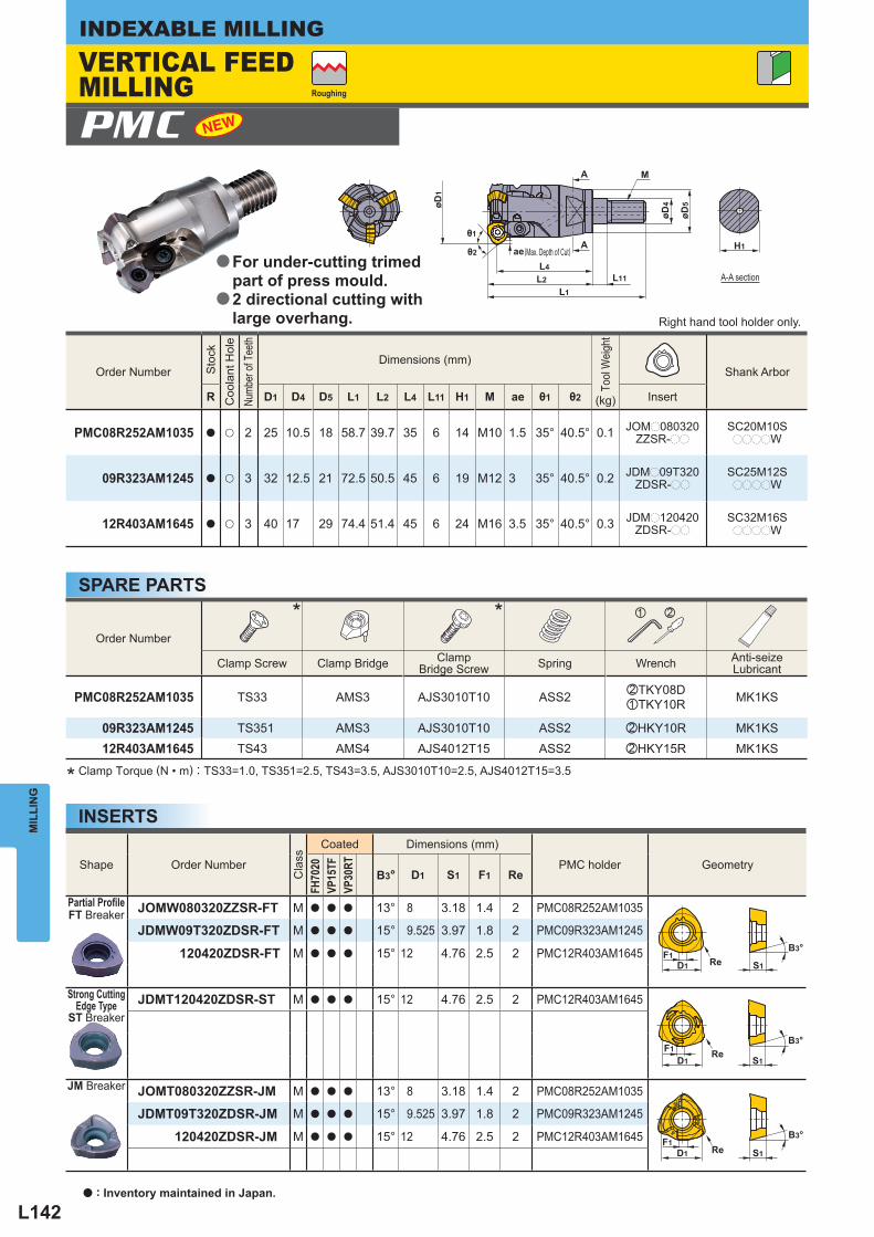
L142
S1ReD1F1
B3°
ReD1
F1B3°
S1
B3°
S1ReD1F1
H1
øD4
øD5
M
øD1
ae
L2L1
L11
A
A
L4
Order Number
Sto
ck
Coo
lant
Hol
e
Numb
er of
Tee
th
Dimensions (mm)
Tool
Wei
ght
(kg)
Shank Arbor
R D1 D4 D5 L1 L2 L4 L11 H1 M ae θ1 θ2 Insert
PMC08R252AM1035 a u 2 25 10.5 18 58.7 39.7 35 6 14 M10 1.5 35° 40.5° 0.1 JOMp080320ZZSR-pp
SC20M10SppppW
09R323AM1245 a u 3 32 12.5 21 72.5 50.5 45 6 19 M12 3 35° 40.5° 0.2 JDMp09T320ZDSR-pp
SC25M12SppppW
12R403AM1645 a u 3 40 17 29 74.4 51.4 45 6 24 M16 3.5 35° 40.5° 0.3 JDMp120420ZDSR-pp
SC32M16SppppW
PMC
Order Number
* * z x
Clamp Screw Clamp Bridge Clamp Bridge Screw Spring Wrench Anti-seize
Lubricant
PMC08R252AM1035 TS33 AMS3 AJS3010T10 ASS2 xTKY08DzTKY10R MK1KS
09R323AM1245 TS351 AMS3 AJS3010T10 ASS2 xHKY10R MK1KS12R403AM1645 TS43 AMS4 AJS4012T15 ASS2 xHKY15R MK1KS
Shape Order Number
Cla
ss
Coated Dimensions (mm)
PMC holder Geometry
FH70
20VP
15TF
VP30
RT
B3° D1 S1 F1 Re
Partial Profi leFT Breaker
JOMW080320ZZSR-FT M a a a 13° 8 3.18 1.4 2 PMC08R252AM1035
JDMW09T320ZDSR-FT M a a a 15° 9.525 3.97 1.8 2 PMC09R323AM1245
120420ZDSR-FT M a a a 15° 12 4.76 2.5 2 PMC12R403AM1645
Strong Cutting
Edge TypeST Breaker
JDMT120420ZDSR-ST M a a a 15° 12 4.76 2.5 2 PMC12R403AM1645
JM Breaker JOMT080320ZZSR-JM M a a a 13° 8 3.18 1.4 2 PMC08R252AM1035
JDMT09T320ZDSR-JM M a a a 15° 9.525 3.97 1.8 2 PMC09R323AM1245
120420ZDSR-JM M a a a 15° 12 4.76 2.5 2 PMC12R403AM1645
MIL
LIN
GINDEXABLE MILLING
INSERTS
* Clamp Torque (N • m) : TS33=1.0, TS351=2.5, TS43=3.5, AJS3010T10=2.5, AJS4012T15=3.5
Right hand tool holder only.
Roughing
VERTICAL FEED MILLING
For under-cutting trimedpart of press mould.2 directional cutting with large overhang.
a
a
A-A section
SPARE PARTS
a : Inventory maintained in Japan.
(Max. Depth of Cut)
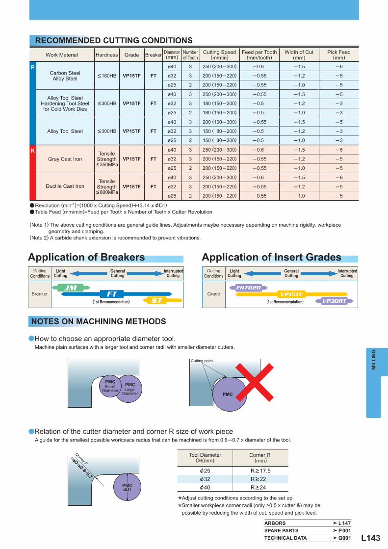
L143
ARBORS L147 SPARE PARTS P001 TECHNICAL DATA Q001
Work Material Hardness Grade Breaker Diameter (mm)
Numberof Teeth
Cutting Speed (m/min)
Feed per Tooth (mm/tooth)
Width of Cut (mm)
Pick Feed (mm)
P Carbon SteelAlloy Steel <180HB VP15TF FT
ø40 3 250 (200─300) ─0.6 ─1.5 ─6
ø32 3 200 (150─220) ─0.55 ─1.2 ─5
ø25 2 200 (150─220) ─0.55 ─1.0 ─5
Alloy Tool SteelHardening Tool Steelfor Cold Work Dies
<300HB VP15TF FT
ø40 3 250 (200─300) ─0.55 ─1.5 ─5
ø32 3 180 (150─200) ─0.5 ─1.2 ─3
ø25 2 180 (150─200) ─0.5 ─1.0 ─3
Alloy Tool Steel <300HB VP15TF FT
ø40 3 200 (100─300) ─0.55 ─1.5 ─5
ø32 3 150 ( 80─200) ─0.5 ─1.2 ─3
ø25 2 150 ( 80─200) ─0.5 ─1.0 ─3
K Gray Cast Iron
Tensile Strength <350MPa
VP15TF FT
ø40 3 250 (200─300) ─0.6 ─1.5 ─6
ø32 3 200 (150─220) ─0.55 ─1.2 ─5
ø25 2 200 (150─220) ─0.55 ─1.0 ─5
Ductile Cast Iron Tensile
Strength <800MPa
VP15TF FT
ø40 3 250 (200─300) ─0.6 ─1.5 ─6
ø32 3 200 (150─220) ─0.55 ─1.2 ─5
ø25 2 200 (150─220) ─0.55 ─1.0 ─5
MIL
LIN
G
RECOMMENDED CUTTING CONDITIONS
a Revolution (min-1)=(1000 x Cutting Speed)u(3.14 x &D1)a Table Feed (mm/min)=Feed per Tooth x Number of Teeth x Cutter Revolution
(Note 1) The above cutting conditions are general guide lines. Adjustments maybe necessary depending on machine rigidity, workpiece geometry and clamping.
(Note 2) A carbide shank extension is recommended to prevent vibrations.
øD1
=øD1x0.6~0.7&25&32&40
a
a
FH7020
VP30RT
JM
STFT VP15TF
Application of Insert Grades
Tool DiameterD1(mm)
Corner R (mm)
CuttingConditions
LightCutting
PMC
R>17.5R>22R>24
(1st Recommendation)
GeneralCutting
CuttingConditions
LightCutting
(1st Recommendation)
GeneralCutting
PMC
PMCLarge
Diameter
PMCSmall
Diameter
InterruptedCutting
InterruptedCutting
Breaker Grade
Application of Breakers
How to choose an appropriate diameter tool.Machine plain surfaces with a larger tool and corner radii with smaller diameter cutters.
NOTES ON MACHINING METHODS
Cutting point
Relation of the cutter diameter and corner R size of work pieceA guide for the smallest possible workpiece radius that can be machined is from 0.6─0.7 x diameter of the tool.
Corner R
*Adjust cutting conditions according to the set up.
*Smaller workpiece corner radii (only >0.5 x cutter &) may be possible by reducing the width of cut, speed and pick feed.
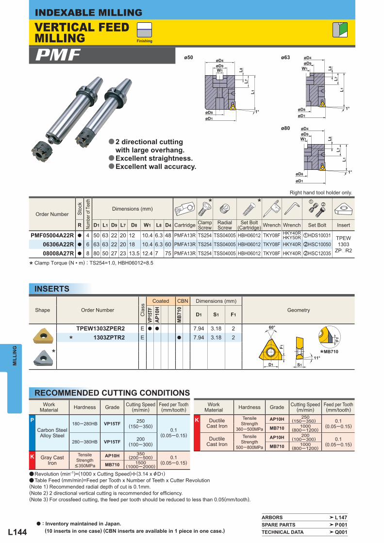
L144
1°øD8
L1
W1 L8L7
øD4ø50 ø63
ø80
øD9
øD1
1°øD8
L8L7
L1
øD9øD4
W1
øD1
1°øD8
øD9øD4
W1 L8
L7L1
øD1
D1
60°
F1
F1
S1
11°
Order Number
Sto
ck
Numb
er of
Tee
th
Dimensions (mm) * * z
x
R D1 L1 D9 L7 D8 W1 L8 D4 Cartridge Clamp Screw
RadialScrew
Set Bolt(Cartridge) Wrench Wrench Set Bolt Insert
PMF05004A22R a 4 50 63 22 20 12 10.4 6.3 48 PMFA13R TS254 TSS04005 HBH06012 TKY08F HKY40RHKY50R zHDS10031 TPEW
1303ZPpR2
06306A22R a 6 63 63 22 20 18 10.4 6.3 60 PMFA13R TS254 TSS04005 HBH06012 TKY08F HKY40R xHSC10050
08008A27R a 8 80 50 27 23 13.5 12.4 7 75 PMFA13R TS254 TSS04005 HBH06012 TKY08F HKY40R xHSC12035
Shape Order Number
Cla
ss
Coated CBN Dimensions (mm)
Geometry
VP15
TFAP
10H
MB7
10
D1 S1 F1
TPEW1303ZPER2 E a a 7.94 3.18 2
* 1303ZPTR2 E a 7.94 3.18 2
*
WorkMaterial Hardness Grade Cutting Speed
(m/min) Feed per Tooth(mm/tooth)
P
Carbon SteelAlloy Steel
180─280HB VP15TF 250(150─350)
0.1(0.05─0.15)
280─380HB VP15TF 200(100─300)
K Gray Cast Iron
Tensile Strength
<350MPa
AP10H 350(200─500) 0.1
(0.05─0.15)MB710 1500(1000─2000)
WorkMaterial Hardness Grade Cutting Speed
(m/min) Feed per Tooth(mm/tooth)
K Ductile Cast Iron
Tensile Strength
360─500MPa
AP10H 250(150─350) 0.1
(0.05─0.15)MB710 1000(800─1200)
Ductile Cast Iron
Tensile Strength
500─800MPa
AP10H 200(100─300) 0.1
(0.05─0.15)MB710 1000(800─1200)
PMF
ARBORS L147 SPARE PARTS P001 TECHNICAL DATA Q001
MIL
LIN
GINDEXABLE MILLING
INSERTS
RECOMMENDED CUTTING CONDITIONS
* Clamp Torque (N • m) : TS254=1.0, HBH06012=8.5
a Revolution (min-1)=(1000 x Cutting Speed)u(3.14 x &D1)a Table Feed (mm/min)=Feed per Tooth x Number of Teeth x Cutter Revolution(Note 1) Recommended radial depth of cut is 0.1mm.(Note 2) 2 directional vertical cutting is recommended for effi ciency.(Note 3) For crossfeed cutting, the feed per tooth should be reduced to less than 0.05(mm/tooth).
*MB710
Finishing
Right hand tool holder only.
VERTICAL FEED MILLING
2 directional cutting with large overhang.Excellent straightness.Excellent wall accuracy.
a
a
a
a : Inventory maintained in Japan. (10 inserts in one case) (CBN inserts are available in 1 piece in one case.)
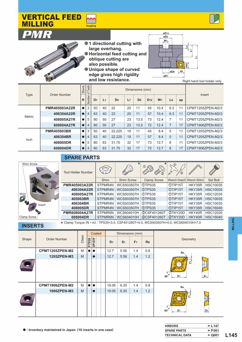
L145
øD9
W1
apøD8
øD1
øD12
L8
L1
(ap)
L7
S1D1
F1
Re
Re
S1D1
F1
80°
80°
ARBORS L147 SPARE PARTS P001 TECHNICAL DATA Q001
Shape Order Number
Cla
ss
Coated Dimensions (mm)
Geometry
F703
0VP
15TF
D1 S1 F1 Re
CPMT1205ZPEN-M2 M a a 12.7 5.56 1.4 0.81205ZPEN-M3 M a 12.7 5.56 1.4 1.2
CPMT1906ZPEN-M2 M a a 19.05 6.35 1.4 0.81906ZPEN-M3 M a 19.05 6.35 1.4 1.2
Type Order Number
Sto
ck
Numb
er of
Tee
th
Dimensions (mm) Insert
R D1 L1 D9 L7 D8 D12 W1 L8 ap
Metric
PMR405003A22R a 3 50 40 22 20 11 45 10.4 6.3 11 CPMT1205ZPEN-M2/3406304A22R a 4 63 40 22 20 11 57 10.4 6.3 11 CPMT1205ZPEN-M2/3
408005A27R a 5 80 50 27 23 13.5 73 12.4 7 11 CPMT1205ZPEN-M2/3608004A27R a 4 80 50 27 23 13.5 72 12.4 7 17 CPMT1906ZPEN-M2/3
Inch
PMR405003BR a 3 50 40 22.225 19 11 45 8.4 5 11 CPMT1205ZPEN-M2/3406304BR a 4 63 40 22.225 19 11 57 8.4 5 11 CPMT1205ZPEN-M2/3
408005DR a 5 80 63 31.75 32 17 73 12.7 8 11 CPMT1205ZPEN-M2/3608004DR a 4 80 63 31.75 32 17 72 12.7 8 17 CPMT1906ZPEN-M2/3
Tool Holder Number
* * z
x
z
x
Shim Shim Screw Clamp Screw Wrench (Insert) Wrench (Shim) Set Bolt PMR405003A22R STPMR4N WCS503507H zTPS35 zTIP15T HKY35R HSC10035
406304A22R STPMR4N WCS503507H zTPS35 zTIP15T HKY35R HSC10035408005A27R STPMR4N WCS503507H zTPS35 zTIP15T HKY35R HSC12035405003BR STPMR4N WCS503507H zTPS35 zTIP15T HKY35R HSC10035406304BR STPMR4N WCS503507H zTPS35 zTIP15T HKY35R HSC10035408005DR STPMR4N WCS503507H zTPS35 zTIP15T HKY35R HSC16040
PMR608004A27R STPMR6N WCS604010H xCSF401260T xTKY20D HKY40R HSC12035608004DR STPMR6N WCS604010H xCSF401260T xTKY20D HKY40R HSC16040
PMR
MIL
LIN
G
INSERTS
SPARE PARTS
* Clamp Torque (N • m) : TPS35=3.5, CSF401260T=5.0, WCS503507H=5.0, WCS604010H=7.0
Shim Screw
Shim
Insert
Clamp Screw
Roughing
Right hand tool holder only.
VERTICAL FEED MILLING
1 directional cutting with large overhang.Horizontal feed cutting and oblique cutting are also possible.Unique shape of curved edge gives high rigidity and low resistance.
a
a
a
a : Inventory maintained in Japan. (10 inserts in one case)
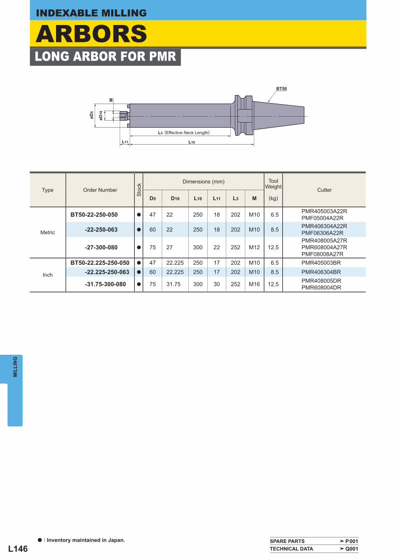
L146
BT50
L3
L10L11
øD5
øD10
M
Type Order Number
Sto
ck
Dimensions (mm)
ToolWeight
(kg) Cutter
D5 D10 L10 L11 L3 M
Metric
BT50-22-250-050 a 47 22 250 18 202 M10 6.5 PMR405003A22RPMF05004A22R
-22-250-063 a 60 22 250 18 202 M10 8.5 PMR406304A22RPMF06306A22R
-27-300-080 a 75 27 300 22 252 M12 12.5PMR408005A27RPMR608004A27RPMF08008A27R
Inch
BT50-22.225-250-050 a 47 22.225 250 17 202 M10 6.5 PMR405003BR-22.225-250-063 a 60 22.225 250 17 202 M10 8.5 PMR406304BR
-31.75-300-080 a 75 31.75 300 30 252 M16 12.5 PMR408005DRPMR608004DR
SPARE PARTS P001 TECHNICAL DATA Q001
MIL
LIN
GINDEXABLE MILLING
LONG ARBOR FOR PMR
(Effective Neck Length)
ARBORS
a : Inventory maintained in Japan.
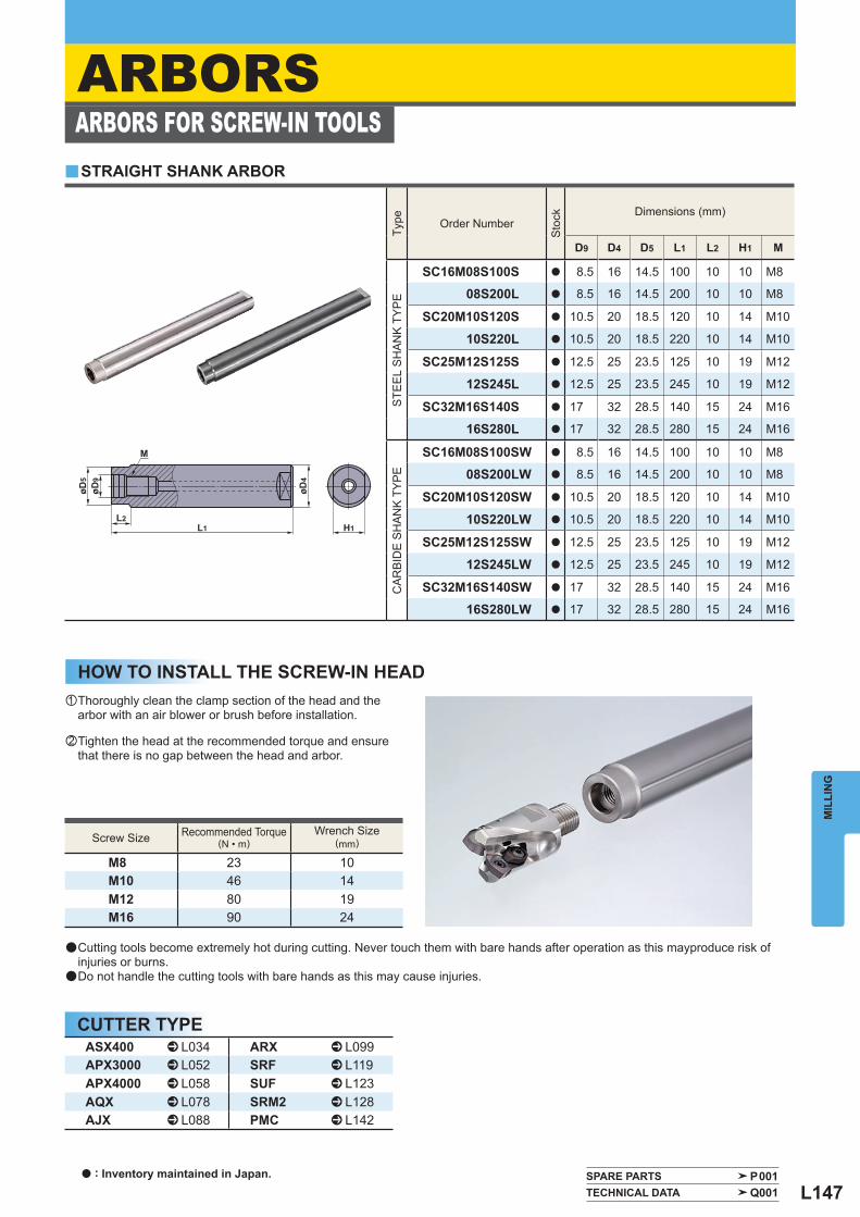
L147
L2L1 H1
øD4
øD5
øD9
M
SPARE PARTS P001 TECHNICAL DATA Q001
Type
Order Number
Sto
ck
Dimensions (mm)
D9 D4 D5 L1 L2 H1 M
STE
EL
SH
AN
K T
YP
E
SC16M08S100S a 8.5 16 14.5 100 10 10 M8
08S200L a 8.5 16 14.5 200 10 10 M8
SC20M10S120S a 10.5 20 18.5 120 10 14 M10
10S220L a 10.5 20 18.5 220 10 14 M10
SC25M12S125S a 12.5 25 23.5 125 10 19 M12
12S245L a 12.5 25 23.5 245 10 19 M12
SC32M16S140S a 17 32 28.5 140 15 24 M16
16S280L a 17 32 28.5 280 15 24 M16
CAR
BID
E SH
ANK
TYPE
SC16M08S100SW a 8.5 16 14.5 100 10 10 M8
08S200LW a 8.5 16 14.5 200 10 10 M8
SC20M10S120SW a 10.5 20 18.5 120 10 14 M10
10S220LW a 10.5 20 18.5 220 10 14 M10
SC25M12S125SW a 12.5 25 23.5 125 10 19 M12
12S245LW a 12.5 25 23.5 245 10 19 M12
SC32M16S140SW a 17 32 28.5 140 15 24 M16
16S280LW a 17 32 28.5 280 15 24 M16
Screw Size Recommended Torque (N • m)
Wrench Size (mm)
M8 23 10M10 46 14M12 80 19M16 90 24
y
ASX400 ^ L034 ARX ^ L099APX3000 ^ L052 SRF ^ L119APX4000 ^ L058 SUF ^ L123AQX ^ L078 SRM2 ^ L128AJX ^ L088 PMC ^ L142
MIL
LIN
G
ARBORS
HOW TO INSTALL THE SCREW-IN HEAD
ARBORS FOR SCREW-IN TOOLSSTRAIGHT SHANK ARBOR
● Cutting tools become extremely hot during cutting. Never touch them with bare hands after operation as this mayproduce risk of injuries or burns.
● Do not handle the cutting tools with bare hands as this may cause injuries.
z Thoroughly clean the clamp section of the head and the arbor with an air blower or brush before installation.
x Tighten the head at the recommended torque and ensure that there is no gap between the head and arbor.
a : Inventory maintained in Japan.
CUTTER TYPE
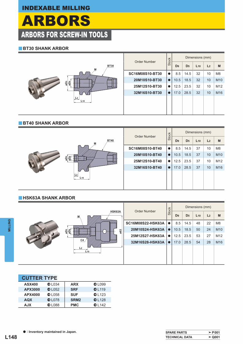
L148
L2L10
øD5
øD9
MBT40
L2L10
øD5
øD9
MBT30
L2L10
øD5
øD9
ø63
M
C4
HSK63A
Order Number
Sto
ck
Dimensions (mm)
D9 D5 L10 L2 M
SC16M08S10-BT30 a 8.5 14.5 32 10 M8
20M10S10-BT30 a 10.5 18.5 32 10 M10
25M12S10-BT30 a 12.5 23.5 32 10 M12
32M16S10-BT30 a 17.0 28.5 32 10 M16
Order Number
Sto
ck
Dimensions (mm)
D9 D5 L10 L2 M
SC16M08S10-BT40 a 8.5 14.5 37 10 M8
20M10S10-BT40 a 10.5 18.5 37 10 M10
25M12S10-BT40 a 12.5 23.5 37 10 M12
32M16S10-BT40 a 17.0 28.5 37 10 M16
Order Number
Sto
ck
Dimensions (mm)
D9 D5 L10 L2 M
SC16M08S22-HSK63A a 8.5 14.5 48 22 M8
20M10S24-HSK63A a 10.5 18.5 50 24 M10
25M12S27-HSK63A a 12.5 23.5 53 27 M12
32M16S28-HSK63A a 17.0 28.5 54 28 M16
y
y
y
SPARE PARTS P001 TECHNICAL DATA Q001
ASX400 ^ L034 ARX ^ L099APX3000 ^ L052 SRF ^ L119APX4000 ^ L058 SUF ^ L123AQX ^ L078 SRM2 ^ L128AJX ^ L088 PMC ^ L142
MIL
LIN
GINDEXABLE MILLING
HSK63A SHANK ARBOR
BT40 SHANK ARBOR
BT30 SHANK ARBOR
ARBORSARBORS FOR SCREW-IN TOOLS
a : Inventory maintained in Japan.
CUTTER TYPE
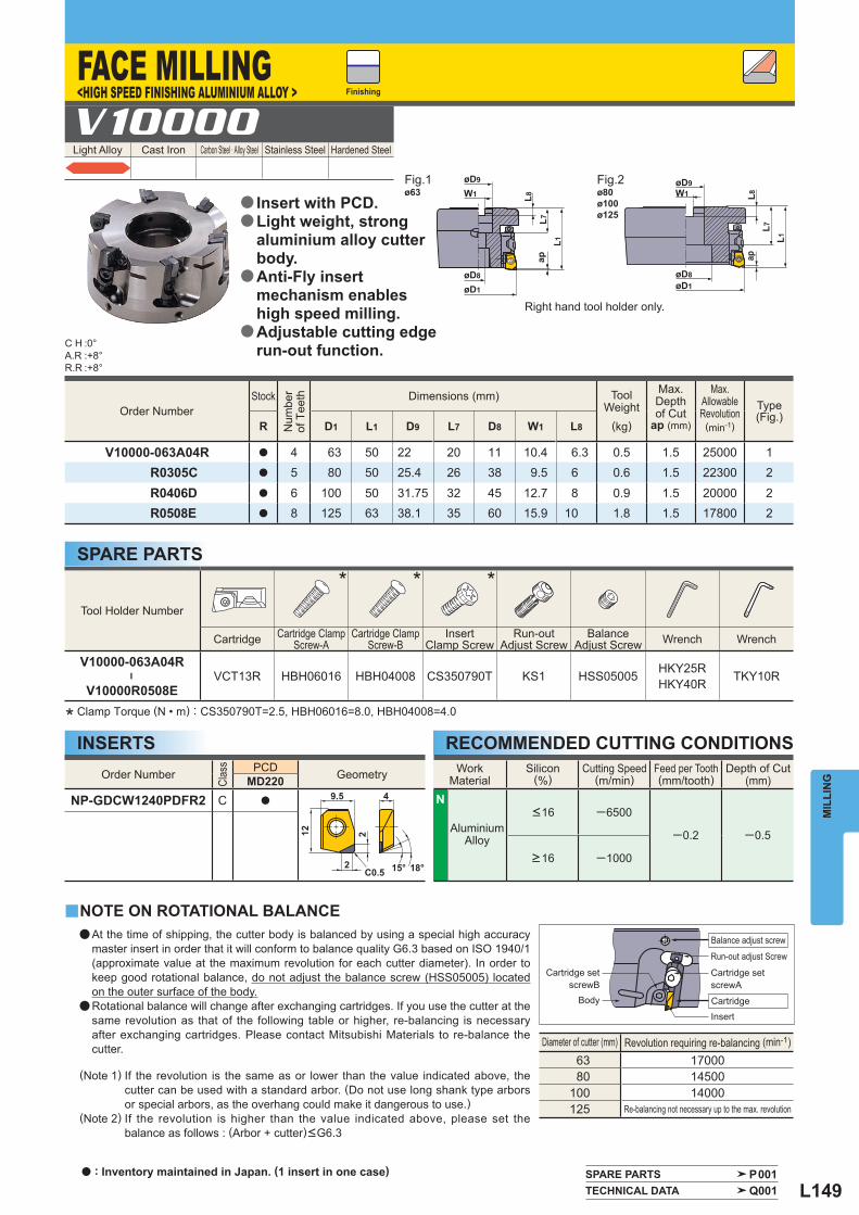
L149
øD8
øD1
øD9
W1 L8L7
ap
L1
øD8øD1
øD9W1 L8
L7ap
L1
ø63 ø80ø100ø125
9.5 4
15° 18°
12 2
C0.52
Light Alloy Cast Iron Carbon Steel · Alloy Steel Stainless Steel Hardened Steel V10000
C H :0°A.R :+8°R.R :+8°
y
SPARE PARTS P001 TECHNICAL DATA Q001
Order Number Stock
Num
ber
of T
eeth
Dimensions (mm)
ToolWeight
(kg)
Max.Depthof Cut ap (mm)
Max.AllowableRevolution (min-1)
Type(Fig.)
R D1 L1 D9 L7 D8 W1 L8
V10000-063A04R a 4 63 50 22 20 11 10.4 6.3 0.5 1.5 25000 1R0305C a 5 80 50 25.4 26 38 9.5 6 0.6 1.5 22300 2
R0406D a 6 100 50 31.75 32 45 12.7 8 0.9 1.5 20000 2R0508E a 8 125 63 38.1 35 60 15.9 10 1.8 1.5 17800 2
Tool Holder Number
* * *
Cartridge Cartridge ClampScrew-A
Cartridge ClampScrew-B
InsertClamp Screw
Run-outAdjust Screw
BalanceAdjust Screw Wrench Wrench
V10000-063A04R
―
V10000R0508EVCT13R HBH06016 HBH04008 CS350790T KS1 HSS05005 HKY25R
HKY40R TKY10R
WorkMaterial
Silicon (%)
Cutting Speed(m/min)
Feed per Tooth(mm/tooth)
Depth of Cut (mm)
N
AluminiumAlloy
<16 ─6500
─0.2 ─0.5
>16 ─1000
Order Number
Clas
s
PCD Geometry MD220NP-GDCW1240PDFR2 C a
Diameter of cutter (mm) Revolution requiring re-balancing (min-1) 63 17000 80 14500100 14000125 Re-balancing not necessary up to the max. revolution
MIL
LIN
G
INSERTS
SPARE PARTS
* Clamp Torque (N • m) : CS350790T=2.5, HBH06016=8.0, HBH04008=4.0
NOTE ON ROTATIONAL BALANCE
(Note 1) If the revolution is the same as or lower than the value indicated above, the cutter can be used with a standard arbor. (Do not use long shank type arbors or special arbors, as the overhang could make it dangerous to use.)
(Note 2) If the revolution is higher than the value indicated above, please set the balance as follows : (Arbor + cutter)<G6.3
RECOMMENDED CUTTING CONDITIONS
Finishing
Fig.1 Fig.2
Right hand tool holder only.
FACE MILLING<HIGH SPEED FINISHING ALUMINIUM ALLOY >
Insert with PCD.Light weight, strong aluminium alloy cutter body.Anti-Fly insert mechanism enables high speed milling. Adjustable cutting edge run-out function.
a
a
a
a
a At the time of shipping, the cutter body is balanced by using a special high accuracy master insert in order that it will conform to balance quality G6.3 based on ISO 1940/1 (approximate value at the maximum revolution for each cutter diameter). In order to keep good rotational balance, do not adjust the balance screw (HSS05005) located on the outer surface of the body.
a Rotational balance will change after exchanging cartridges. If you use the cutter at the same revolution as that of the following table or higher, re-balancing is necessary after exchanging cartridges. Please contact Mitsubishi Materials to re-balance the cutter.
Cartridge set screwB
Cartridge set screwA
Body
Run-out adjust Screw
Balance adjust screw
CartridgeInsert
a : Inventory maintained in Japan. (1 insert in one case)
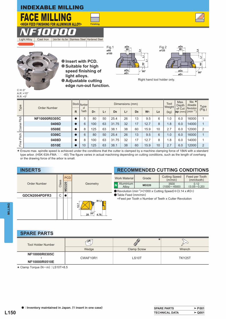
L150
L8L7
øD9W1
L1ap
øD8øD1
90°
ap
90°
øD9W1 L8
L7L1
øD1
øD8
ø80ø100
ø125
4.76
R1.2
12.7
20 20°
Light Alloy Cast Iron Carbon Steel · Alloy Steel Stainless Steel Hardened Steel NF10000
Tool Holder Number *
Wedge Clamp Screw Wrench
NF10000R0305C
―
NF10000R0510ECWAF10R1 LS10T TKY25T
Order Number
Cla
ss
PCD
Geometry
MD
220
GDCN2004PDFR3 C a
Type
Order Number Stock Number
of Teeth
Dimensions (mm)
ToolWeight
(kg)
Max.Depthof Cut ap (mm)
Max.
AllowableRevolution(min-1)
Type(Fig.)
R D1 L1 D9 L7 D8 W1 L8
Coar
se P
itch
NF10000R0305C a 5 80 50 25.4 26 13 9.5 6 1.0 6.0 16000 10406D a 6 100 63 31.75 32 17 12.7 8 1.8 6.0 14000 10508E a 8 125 63 38.1 38 60 15.9 10 2.7 6.0 12000 2
Fine
Pitc
h
0306C a 6 80 50 25.4 26 13 9.5 6 1.0 6.0 16000 10408D a 8 100 63 31.75 32 17 12.7 8 1.8 6.0 14000 10510E a 10 125 63 38.1 38 60 15.9 10 2.7 6.0 12000 2
Work Material Grade Cutting Speed(m/min)
Feed per Tooth(mm/tooth)
N AluminiumAlloy MD220 3500
(1000─ 4500)0.12
(0.05─0.20)
C H :0°A.R :+10°R.R :+5°
SPARE PARTS P001 TECHNICAL DATA Q001
*
MIL
LIN
GINDEXABLE MILLING
INSERTS RECOMMENDED CUTTING CONDITIONS
SPARE PARTS
* Ensure max. spindle speed is achieved under the conditions that the cutter is clamped by a machine clamping force of 18kN with a standard type arbor. (HSK 63A-FMAppp-60) The fi gure varies in actual machining depending on cutting conditions, such as the length of overhang or the drawing force of the arbor is small.
* Clamp Torque (N • m) : LS10T=8.5
Finishing
Fig.1 Fig.2
Right hand tool holder only.
a Revolution (min-1)=(1000 x Cutting Speed)u(3.14 x &D1)a Table Feed (mm/min) =Feed per Tooth x Number of Teeth x Cutter Revolution
FACE MILLING<HIGH FEED FINISHING FOR ALUMINIUM ALLOY>
Insert with PCD.Suitable for high speed fi nishing of light alloys.Adjustable cutting edge run-out function.
a
a
a
a : Inventory maintained in Japan. (1 insert in one case)
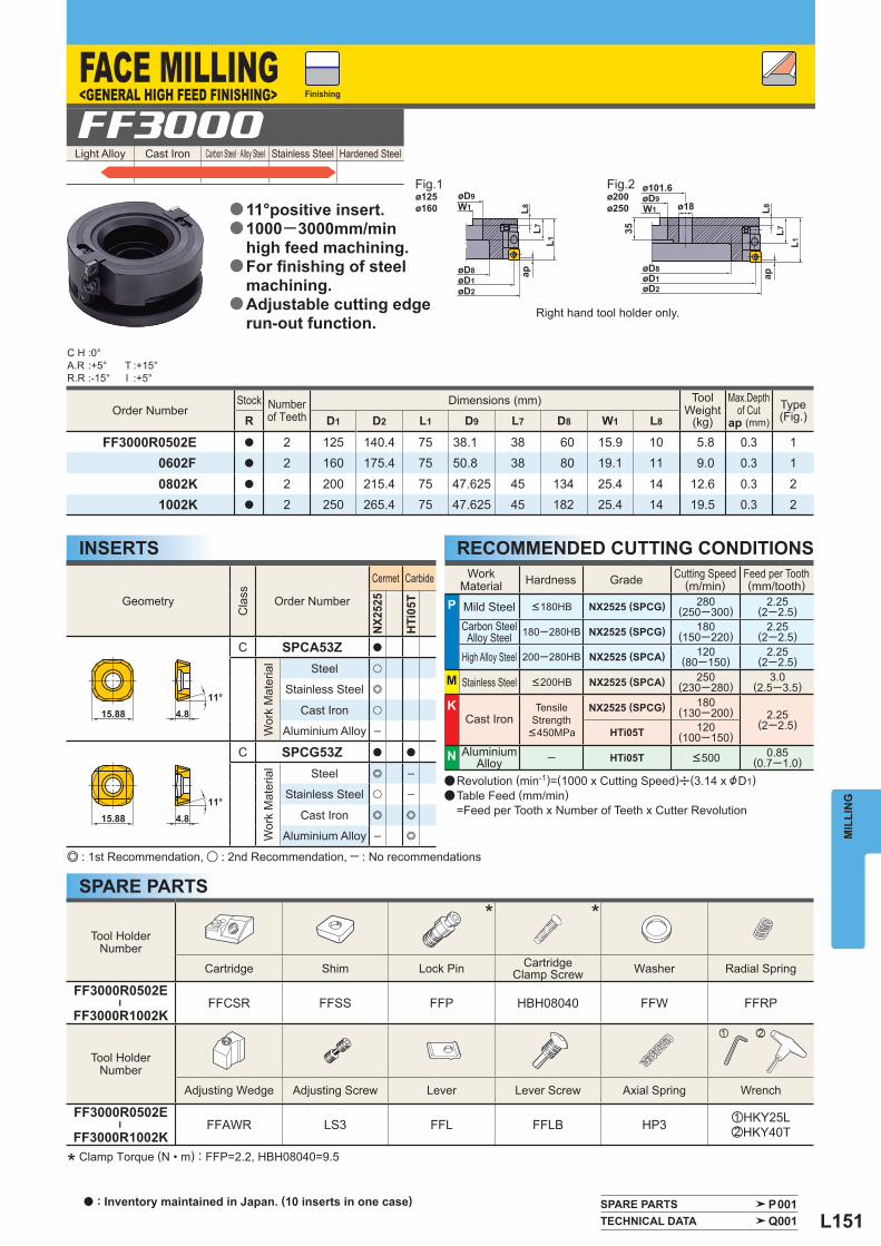
L151
øD9W1 L8
L7L1
øD8øD1øD2
øD9W1
ø101.6
ø18
øD1øD8
øD2
L8L7
L1
35
ap ap
ø125ø160
ø200ø250
11°15.88 4.8
15.88 4.811°
Light Alloy Cast Iron Carbon Steel · Alloy Steel Stainless Steel Hardened Steel FF3000
Order Number Stock Number
of Teeth Dimensions (mm)
Tool
Weight(kg)
Max.Depth
of Cutap (mm)
Type(Fig.) R D1 D2 L1 D9 L7 D8 W1 L8
FF3000R0502E a 2 125 140.4 75 38.1 38 60 15.9 10 5.8 0.3 10602F a 2 160 175.4 75 50.8 38 80 19.1 11 9.0 0.3 1
0802K a 2 200 215.4 75 47.625 45 134 25.4 14 12.6 0.3 21002K a 2 250 265.4 75 47.625 45 182 25.4 14 19.5 0.3 2
Tool HolderNumber
* *
Cartridge Shim Lock Pin Cartridge Clamp Screw Washer Radial Spring
FF3000R0502E
―
FF3000R1002KFFCSR FFSS FFP HBH08040 FFW FFRP
Tool HolderNumber
z x
Adjusting Wedge Adjusting Screw Lever Lever Screw Axial Spring Wrench
FF3000R0502E
―
FF3000R1002KFFAWR LS3 FFL FFLB HP3 zHKY25L
xHKY40T
WorkMaterial Hardness Grade Cutting Speed
(m/min) Feed per Tooth(mm/tooth)
P Mild Steel <180HB NX2525 (SPCG) 280(250─300)
2.25(2─2.5)
Carbon SteelAlloy Steel 180─280HB NX2525 (SPCG) 180
(150─220)2.25
(2─2.5)
High Alloy Steel 200─280HB NX2525 (SPCA) 120(80─150)
2.25(2─2.5)
M Stainless Steel <200HB NX2525 (SPCA) 250(230─280)
3.0(2.5─3.5)
K Cast Iron
Tensile Strength
<450MPa
NX2525 (SPCG) 180(130─200) 2.25
(2─2.5)HTi05T 120
(100─150)
N AluminiumAlloy ─ HTi05T <500 0.85
(0.7─1.0)
Geometry
Cla
ss
Order Number
Cermet Carbide
NX25
25
HTi
05T
C SPCA53Z a
Wor
k M
ater
ial
Steel u
Stainless Steel e
Cast Iron u
Aluminium Alloy ─
C SPCG53Z a a
Wor
k M
ater
ial
Steel e ─
Stainless Steel u ─
Cast Iron e e
Aluminium Alloy ─ e
C H :0°A.R :+5°R.R :-15°
T :+15°I :+5°
SPARE PARTS P001 TECHNICAL DATA Q001
MIL
LIN
G
INSERTS RECOMMENDED CUTTING CONDITIONS
SPARE PARTSe : 1st Recommendation, u : 2nd Recommendation, ─ : No recommendations
Finishing
Fig.1 Fig.2
Right hand tool holder only.
a Revolution (min-1)=(1000 x Cutting Speed)u(3.14 x &D1)a Table Feed (mm/min) =Feed per Tooth x Number of Teeth x Cutter Revolution
FACE MILLING<GENERAL HIGH FEED FINISHING>
11°positive insert.1000─3000mm/min high feed machining.For fi nishing of steelmachining.Adjustable cutting edge run-out function.
a
a
a
a
* Clamp Torque (N • m) : FFP=2.2, HBH08040=9.5
a : Inventory maintained in Japan. (10 inserts in one case)
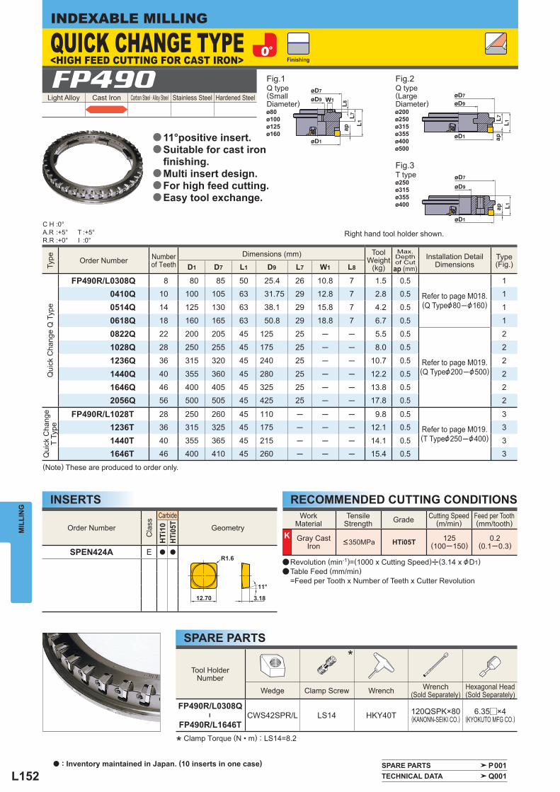
L152
øD9 W1
øD7
L8L7
ap
øD1
L1
øD9
øD1
øD7
L7ap
L1
øD9
øD1
øD7
ap L1
11°
3.18
R1.6
12.70
Light Alloy Cast Iron Carbon Steel · Alloy Steel Stainless Steel Hardened Steel FP490
Tool HolderNumber
*
Wedge Clamp Screw Wrench Wrench(Sold Separately)
Hexagonal Head(Sold Separately)
FP490R/L0308Q
―
FP490R/L1646TCWS42SPR/L LS14 HKY40T 120QSPK×80
(KANONN-SEIKI CO.) 6.35r×4
(KYOKUTO MFG CO.)
WorkMaterial
Tensile Strength Grade Cutting Speed
(m/min) Feed per Tooth(mm/tooth)
K Gray Cast Iron <350MPa HTi05T 125
(100─150)0.2
(0.1─0.3)
Order Number
Cla
ss
Carbide
Geometry
HTi
10HT
i05T
SPEN424A E a a
Type
Order Number Number of Teeth
Dimensions (mm)
ToolWeight
(kg)
Max. Depthof Cut
ap (mm) Installation Detail
Dimensions Type(Fig.) D1 D7 L1 D9 L7 W1 L8
Qui
ck C
hang
e Q
Typ
e
FP490R/L0308Q 8 80 85 50 25.4 26 10.8 7 1.5 0.5
Refer to page M018.(Q Type&80─&160)
10410Q 10 100 105 63 31.75 29 12.8 7 2.8 0.5 1
0514Q 14 125 130 63 38.1 29 15.8 7 4.2 0.5 1
0618Q 18 160 165 63 50.8 29 18.8 7 6.7 0.5 1
0822Q 22 200 205 45 125 25 ─ ─ 5.5 0.5
Refer to page M019.(Q Type&200─&500)
2
1028Q 28 250 255 45 175 25 ─ ─ 8.0 0.5 2
1236Q 36 315 320 45 240 25 ─ ─ 10.7 0.5 2
1440Q 40 355 360 45 280 25 ─ ─ 12.2 0.5 2
1646Q 46 400 405 45 325 25 ─ ─ 13.8 0.5 22056Q 56 500 505 45 425 25 ─ ─ 17.8 0.5 2
Qui
ck C
hang
e T
Type
FP490R/L1028T 28 250 260 45 110 ─ ─ ─ 9.8 0.5
Refer to page M019.(T Type&250─&400)
31236T 36 315 325 45 175 ─ ─ ─ 12.1 0.5 3
1440T 40 355 365 45 215 ─ ─ ─ 14.1 0.5 31646T 46 400 410 45 260 ─ ─ ─ 15.4 0.5 3
C H :0°A.R :+5°R.R :+0°
T :+5°I :0°
SPARE PARTS P001 TECHNICAL DATA Q001
MIL
LIN
GINDEXABLE MILLING
INSERTS RECOMMENDED CUTTING CONDITIONS
SPARE PARTS
(Note) These are produced to order only.
* Clamp Torque (N • m) : LS14=8.2
Q type (SmallDiameter)
Q type (LargeDiameter)
T type
Finishing
Fig.1 Fig.2
Fig.3
Right hand tool holder shown.
a Revolution (min-1)=(1000 x Cutting Speed)u(3.14 x &D1)a Table Feed (mm/min) =Feed per Tooth x Number of Teeth x Cutter Revolution
<HIGH FEED CUTTING FOR CAST IRON>QUICK CHANGE TYPE
11°positive insert.Suitable for cast ironfi nishing.Multi insert design.For high feed cutting.Easy tool exchange.
a
a
a
a
a
ø80ø100ø125ø160
ø200ø250ø315ø355ø400ø500
ø250ø315ø355ø400
a : Inventory maintained in Japan. (10 inserts in one case)
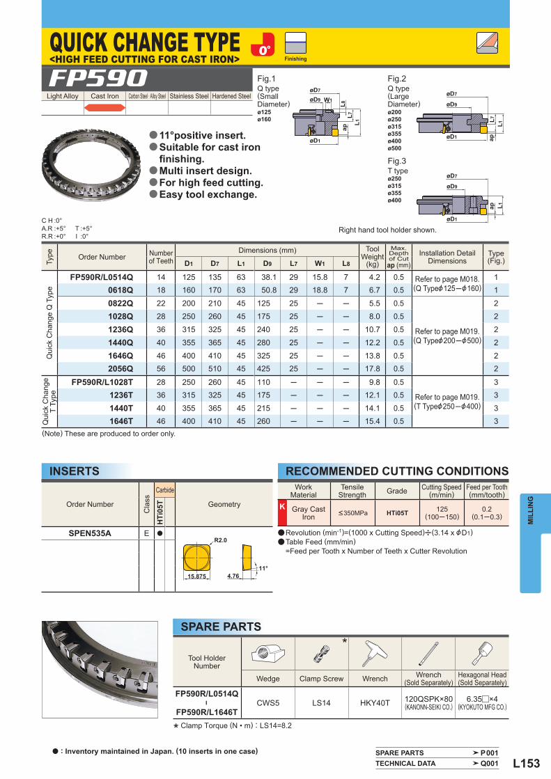
L153
øD9 W1
øD7
L8L7
L1
øD1
ap
øD9
øD1
øD7
L7ap
L1
øD9
øD1
øD7
ap L1
R2.0
15.87511°
4.76
Light Alloy Cast Iron Carbon Steel · Alloy Steel Stainless Steel Hardened Steel FP590
Tool HolderNumber
*
Wedge Clamp Screw Wrench Wrench(Sold Separately)
Hexagonal Head(Sold Separately)
FP590R/L0514Q
―
FP590R/L1646TCWS5 LS14 HKY40T 120QSPK×80
(KANONN-SEIKI CO.) 6.35r×4
(KYOKUTO MFG CO.)
WorkMaterial
Tensile Strength Grade Cutting Speed
(m/min) Feed per Tooth(mm/tooth)
K Gray Cast Iron <350MPa HTi05T 125
(100─150)0.2
(0.1─0.3)
Order Number
Cla
ss
Carbide
Geometry
HTi
05T
SPEN535A E a
Type
Order Number Number of Teeth
Dimensions (mm)
ToolWeight
(kg)
Max. Depthof Cut
ap (mm) Installation Detail
Dimensions Type(Fig.) D1 D7 L1 D9 L7 W1 L8
Qui
ck C
hang
e Q
Typ
e
FP590R/L0514Q 14 125 135 63 38.1 29 15.8 7 4.2 0.5 Refer to page M018.(Q Type&125─&160)
10618Q 18 160 170 63 50.8 29 18.8 7 6.7 0.5 1
0822Q 22 200 210 45 125 25 ─ ─ 5.5 0.5
Refer to page M019.(Q Type&200─&500)
2
1028Q 28 250 260 45 175 25 ─ ─ 8.0 0.5 2
1236Q 36 315 325 45 240 25 ─ ─ 10.7 0.5 2
1440Q 40 355 365 45 280 25 ─ ─ 12.2 0.5 2
1646Q 46 400 410 45 325 25 ─ ─ 13.8 0.5 22056Q 56 500 510 45 425 25 ─ ─ 17.8 0.5 2
Qui
ck C
hang
e T
Type
FP590R/L1028T 28 250 260 45 110 ─ ─ ─ 9.8 0.5
Refer to page M019.(T Type&250─&400)
31236T 36 315 325 45 175 ─ ─ ─ 12.1 0.5 3
1440T 40 355 365 45 215 ─ ─ ─ 14.1 0.5 31646T 46 400 410 45 260 ─ ─ ─ 15.4 0.5 3
C H :0°A.R :+5°R.R :+0°
T :+5°I :0°
SPARE PARTS P001 TECHNICAL DATA Q001
MIL
LIN
G
INSERTS RECOMMENDED CUTTING CONDITIONS
SPARE PARTS
* Clamp Torque (N • m) : LS14=8.2
Finishing
Right hand tool holder shown.
a Revolution (min-1)=(1000 x Cutting Speed)u(3.14 x &D1)a Table Feed (mm/min) =Feed per Tooth x Number of Teeth x Cutter Revolution
QUICK CHANGE TYPE<HIGH FEED CUTTING FOR CAST IRON>
11°positive insert.Suitable for cast ironfi nishing.Multi insert design.For high feed cutting.Easy tool exchange.
a
a
a
a
a
Fig.1 Fig.2
Fig.3
ø125ø160
ø200ø250ø315ø355ø400ø500
ø250ø315ø355ø400
Q type (SmallDiameter)
Q type (LargeDiameter)
T type
(Note) These are produced to order only.
a : Inventory maintained in Japan. (10 inserts in one case)
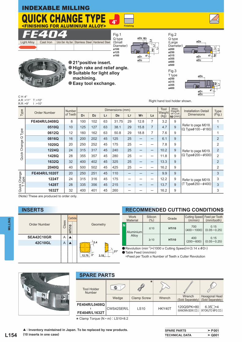
L154
øD9
øD2øD1
W1
4°
L8L7
ap
L1
øD9
øD2øD1 4°
L7ap
L1
øD9
øD2øD1 4°
L1
ap
21°
2.4
3.1812.70 3°
Light Alloy Cast Iron Carbon Steel · Alloy Steel Stainless Steel Hardened Steel FE404
Tool HolderNumber
*
Wedge Clamp Screw Wrench Wrench(Sold Separately)
Hexagonal Head(Sold Separately)
FE404R/L0408Q
―
FE404R/L1632TCWS42SER/L LS10 HKY40T 120QSPK×80
(KANONN-SEIKI CO.) 6.35r×4
(KYOKUTO MFG CO.)
Order Number
Cla
ss
Carbide
Geometry
HTi
10
SEA42C10GR A [
42C10GL A [
Type
Order Number Number of Teeth
Dimensions (mm)
ToolWeight
(kg)
Max. Depthof Cut
ap (mm) Installation Detail
Dimensions Type(Fig.) D1 D2 L1 D9 L7 W1 L8
Qui
ck C
hang
e Q
Typ
e
FE404R/L0408Q 8 100 102 63 31.75 29 12.8 7 3.2 9 Refer to page M018.(Q Type&100─&160)
10510Q 10 125 127 63 38.1 29 15.8 7 4.7 9 1
0612Q 12 160 162 63 50.8 29 18.8 7 7.6 9 1
0816Q 16 200 202 45 125 25 ─ ─ 6.1 9
Refer to page M019.(Q Type&200─&500)
2
1020Q 20 250 252 45 175 25 ─ ─ 7.8 9 2
1224Q 24 315 317 45 240 25 ─ ─ 10.2 9 2
1428Q 28 355 357 45 280 25 ─ ─ 11.8 9 2
1632Q 32 400 402 45 325 25 ─ ─ 13.3 9 22040Q 40 500 502 45 425 25 ─ ─ 16.2 9 2
Qui
ck C
hang
e T
Type
FE404R/L1020T 20 250 251 45 110 ─ ─ ─ 9.9 9
Refer to page M019.(T Type&250─&400)
31224T 24 315 316 45 175 ─ ─ ─ 12.2 9 3
1428T 28 335 356 45 215 ─ ─ ─ 13.7 9 31632T 32 400 401 45 260 ─ ─ ─ 16.2 9 3
WorkMaterial
Silicon (%) Grade Cutting Speed
(m/min) Feed per Tooth(mm/tooth)
N
AluminiumAlloy
<10 HTi10 700(400─1000)
0.15(0.05─0.25)
>10 HTi10 400(200─600)
0.15(0.05─0.25)
C H :4°A.R :+11°R.R :+9°
T :+10°I :+10°
SPARE PARTS P001 TECHNICAL DATA Q001
MIL
LIN
GINDEXABLE MILLING
INSERTS RECOMMENDED CUTTING CONDITIONS
SPARE PARTS
* Clamp Torque (N • m) : LS10=8.2
Finishing
Right hand tool holder shown.
a Revolution (min-1)=(1000 x Cutting Speed)u(3.14 x &D1)a Table Feed (mm/min) =Feed per Tooth x Number of Teeth x Cutter Revolution
QUICK CHANGE TYPEFig.1 Fig.2
Fig.3
ø100ø125ø160
ø200ø250ø315ø355ø400ø500
ø250ø315ø355ø400
Q type (SmallDiameter)
Q type (LargeDiameter)
T type
(Note) These are produced to order only.
21°positive insert.High rake and relief angle.Suitable for light alloy machining.Easy tool exchange.
a
a
a
a
<FINISHING FOR ALUMINIUM ALLOY>
[ : Inventory maintained in Japan. To be replaced by new products. (10 inserts in one case)
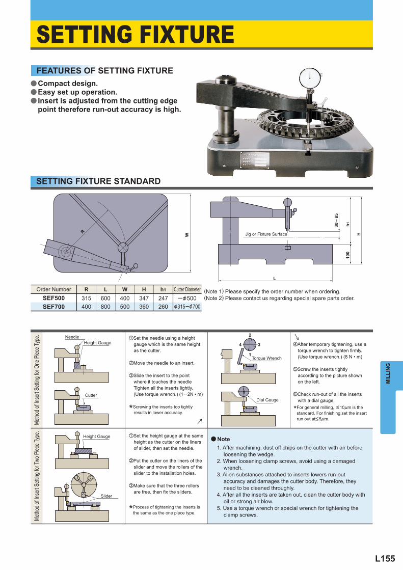
L155
MIL
LIN
G
SETTING FIXTURE
R
W H
L
100
30 –
85
h1
2
1
3 4
R L W H h1
SEF500 315 400
600 400 347 247 ─&500 &315─&700 800 500 360 260 SEF700
a
zSet the needle using a height gauge which is the same height as the cutter.
xMove the needle to an insert.
cSlide the insert to the point where it touches the needle Tighten all the inserts lightly. (Use torque wrench.) (1─2N • m)
vAfter temporary tightening, use a torque wrench to tighten firmly. (Use torque wrench.) (8 N • m)
bScrew the inserts tightly according to the picture shown on the left.
nCheck run-out of all the inserts with a dial gauge.
zSet the height gauge at the same height as the cutter on the liners of slider, then set the needle.
xPut the cutter on the liners of the slider and move the rollers of the slider to the installation holes.
cMake sure that the three rollers are free, then fix the sliders.
*Screwing the inserts too tightly results in lower accuracy.
Jig or Fixture Surface
SETTING FIXTURE STANDARD
FEATURES OF SETTING FIXTURE
Order Number Cutter Diameter (Note 1) Please specify the order number when ordering.(Note 2) Please contact us regarding special spare parts order.
Metho
d of In
sert
Settin
g for
One
Piec
e Typ
e.Me
thod o
f Inse
rt Se
tting f
or Tw
o Piec
e Typ
e.
Slider
Height Gauge
Height Gauge
Cutter
Needle
*Process of tightening the inserts is the same as the one piece type.
Note1. After machining, dust off chips on the cutter with air before
loosening the wedge.2. When loosening clamp screws, avoid using a damaged
wrench.3. Alien substances attached to inserts lowers run-out
accuracy and damages the cutter body. Therefore, they need to be cleaned throughly.
4. After all the inserts are taken out, clean the cutter body with oil or strong air blow.
5. Use a torque wrench or special wrench for tightening the clamp screws.
Torque Wrench
Dial Gauge
*For general milling, <10!m is the standard. For finishing,set the insert
run out at<5!m.
a
a
a
Compact design.Easy set up operation.Insert is adjusted from the cutting edge point therefore run-out accuracy is high.
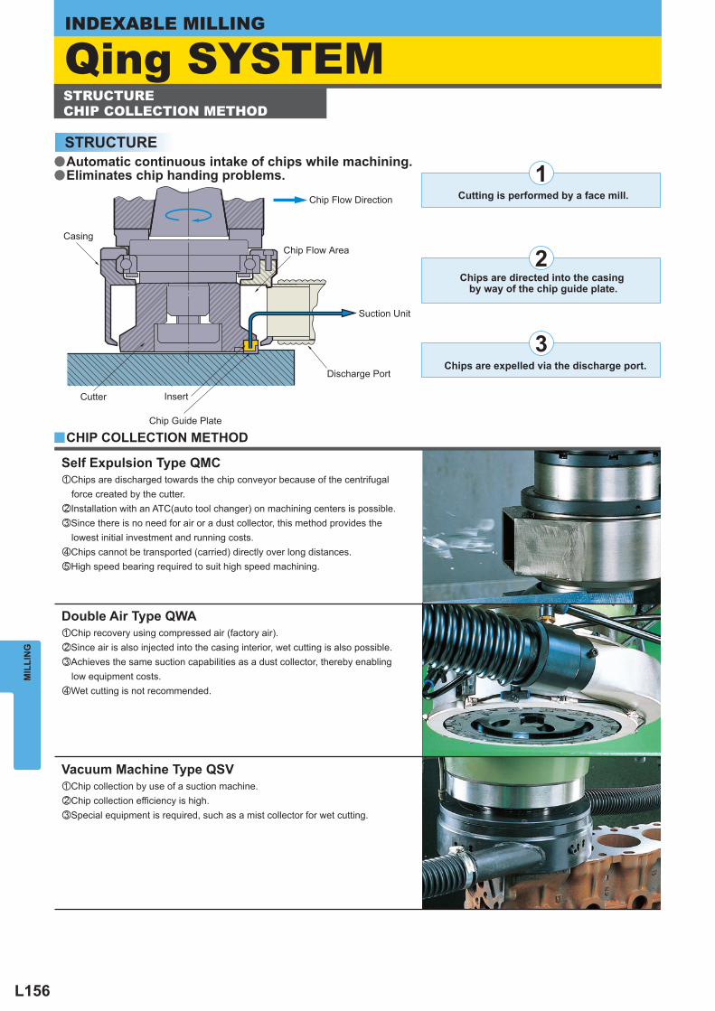
L156
MIL
LIN
GINDEXABLE MILLING
1
2
3
y
zChips are discharged towards the chip conveyor because of the centrifugal force created by the cutter.xInstallation with an ATC(auto tool changer) on machining centers is possible.cSince there is no need for air or a dust collector, this method provides the lowest initial investment and running costs.vChips cannot be transported (carried) directly over long distances. bHigh speed bearing required to suit high speed machining.
zChip recovery using compressed air (factory air).xSince air is also injected into the casing interior, wet cutting is also possible.cAchieves the same suction capabilities as a dust collector, thereby enabling low equipment costs.vWet cutting is not recommended.
zChip collection by use of a suction machine. xChip collection efficiency is high. cSpecial equipment is required, such as a mist collector for wet cutting.
STRUCTURE
Discharge Port
Insert
Chip Guide Plate
Cutter
CasingChip Flow Area
Chip Flow Direction
Suction Unit
Cutting is performed by a face mill.
Chips are expelled via the discharge port.
CHIP COLLECTION METHOD
Self Expulsion Type QMC
Double Air Type QWA
Vacuum Machine Type QSV
Chips are directed into the casing by way of the chip guide plate.
STRUCTURE CHIP COLLECTION METHOD
aa
Automatic continuous intake of chips while machining.Eliminates chip handing problems.
Qing SYSTEM
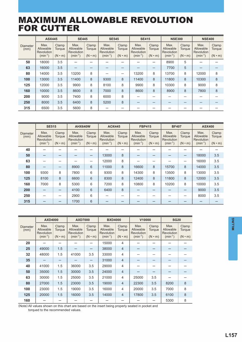
L157
Diameter (mm)
ASX445 SE445 SE545 SE415 NSE300 NSE400
Max.
AllowableRevolution
(min-1)
ClampTorque
(N • m)
Max.AllowableRevolution
(min-1)
ClampTorque
(N • m)
Max.AllowableRevolution
(min-1)
ClampTorque
(N • m)
Max.AllowableRevolution
(min-1)
ClampTorque
(N • m)
Max.AllowableRevolution
(min-1)
ClampTorque
(N • m)
Max.AllowableRevolution
(min-1)
ClampTorque
(N • m)
50 18000 3.5 ─ ─ ─ ─ ─ ─ 8900 5 ─ ─ 63 16000 3.5 ─ ─ ─ ─ ─ ─ 7700 5 ─ ─
80 14000 3.5 13200 8 ─ ─ 13200 8 13700 8 12000 8
100 13000 3.5 11400 8 9300 8 11400 8 11800 8 10300 8
125 12000 3.5 9900 8 8100 8 9900 8 10300 8 9000 8
160 10000 3.5 8600 8 7000 8 8600 8 8900 8 7800 8
200 9000 3.5 7400 8 6000 8 ─ ─ ─ ─ ─ ─
250 8000 3.5 6400 8 5200 8 ─ ─ ─ ─ ─ ─315 6500 3.5 5600 8 ─ ─ ─ ─ ─ ─ ─ ─
Diameter (mm)
SE515 AHX640W AOX445 FBP415 BF407 ASX400
Max.
AllowableRevolution
(min-1)
ClampTorque
(N • m)
Max.AllowableRevolution
(min-1)
ClampTorque
(N • m)
Max.AllowableRevolution
(min-1)
ClampTorque
(N • m)
Max.AllowableRevolution
(min-1)
ClampTorque
(N • m)
Max.AllowableRevolution
(min-1)
ClampTorque
(N • m)
Max.AllowableRevolution
(min-1)
ClampTorque
(N • m)
40 ─ ─ ─ ─ ─ ─ ─ ─ ─ ─ ─ ─ 50 ─ ─ ─ ─ 13000 8 ─ ─ ─ ─ 18000 3.5
63 ─ ─ ─ ─ 12000 8 ─ ─ ─ ─ 16000 3.5
80 ─ ─ 8900 6 11000 8 16600 8 15700 8 14000 3.5
100 9300 8 7800 6 9300 8 14300 8 13500 8 13000 3.5
125 8100 8 6600 6 8300 8 12400 8 11800 8 12000 3.5
160 7000 8 5300 6 7200 8 10800 8 10200 8 10000 3.5
200 ─ ─ 4100 6 6400 8 ─ ─ ─ ─ 9000 3.5
250 ─ ─ 2900 6 ─ ─ ─ ─ ─ ─ 8000 3.5315 ─ ─ 1700 6 ─ ─ ─ ─ ─ ─ ─ ─
Diameter (mm)
AXD4000 AXD7000 BXD4000 V10000 SG20
Max.
AllowableRevolution
(min-1)
ClampTorque
(N • m)
Max.AllowableRevolution
(min-1)
ClampTorque
(N • m)
Max.AllowableRevolution
(min-1)
ClampTorque
(N • m)
Max.AllowableRevolution
(min-1)
ClampTorque
(N • m)
Max.AllowableRevolution
(min-1)
ClampTorque
(N • m)
20 ─ ─ ─ ─ 15000 4 ─ ─ ─ ─ 25 49000 1.5 ─ ─ 38000 4 ─ ─ ─ ─
32 48000 1.5 41000 3.5 33000 4 ─ ─ ─ ─
35 ─ ─ ─ ─ 31000 4 ─ ─ ─ ─
40 41000 1.5 36000 3.5 29000 4 ─ ─ ─ ─
50 35000 1.5 30000 3.5 24000 4 ─ ─ ─ ─
63 30000 1.5 25000 3.5 21000 4 25000 3.5 ─ ─
80 27000 1.5 23000 3.5 19000 4 22300 3.5 8200 8
100 23000 1.5 19000 3.5 16000 4 20000 3.5 7000 8
125 20000 1.5 16000 3.5 14000 4 17800 3.5 6100 8160 ─ ─ ─ ─ ─ ─ ─ ─ 5300 8
MIL
LIN
G
(Note) All values shown on this chart are based on the insert being properly seated in pocket and torqued to the recommended values.
MAXIMUM ALLOWABLE REVOLUTIONFOR CUTTER
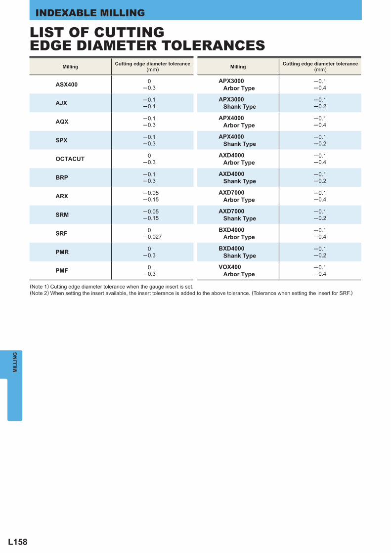
L158
Milling Cutting edge diameter tolerance (mm)
ASX400 0─0.3
AJX ─0.1─0.4
AQX ─0.1─0.3
SPX ─0.1─0.3
OCTACUT 0─0.3
BRP ─0.1─0.3
ARX ─0.05─0.15
SRM ─0.05─0.15
SRF 0─0.027
PMR 0─0.3
PMF 0─0.3
Milling Cutting edge diameter tolerance (mm)
APX3000 Arbor Type
─0.1─0.4
APX3000 Shank Type
─0.1─0.2
APX4000 Arbor Type
─0.1─0.4
APX4000 Shank Type
─0.1─0.2
AXD4000 Arbor Type
─0.1─0.4
AXD4000 Shank Type
─0.1─0.2
AXD7000 Arbor Type
─0.1─0.4
AXD7000 Shank Type
─0.1─0.2
BXD4000 Arbor Type
─0.1─0.4
BXD4000 Shank Type
─0.1─0.2
VOX400 Arbor Type
─0.1─0.4
MIL
LIN
GINDEXABLE MILLING
(Note 1) Cutting edge diameter tolerance when the gauge insert is set. (Note 2) When setting the insert available, the insert tolerance is added to the above tolerance. (Tolerance when setting the insert for SRF.)
LIST OF CUTTINGEDGE DIAMETER TOLERANCES

L159
Memo
Recommended