1400 SERIES HOSE REEL MANUAL967000.6.0
www.conductix.us
1
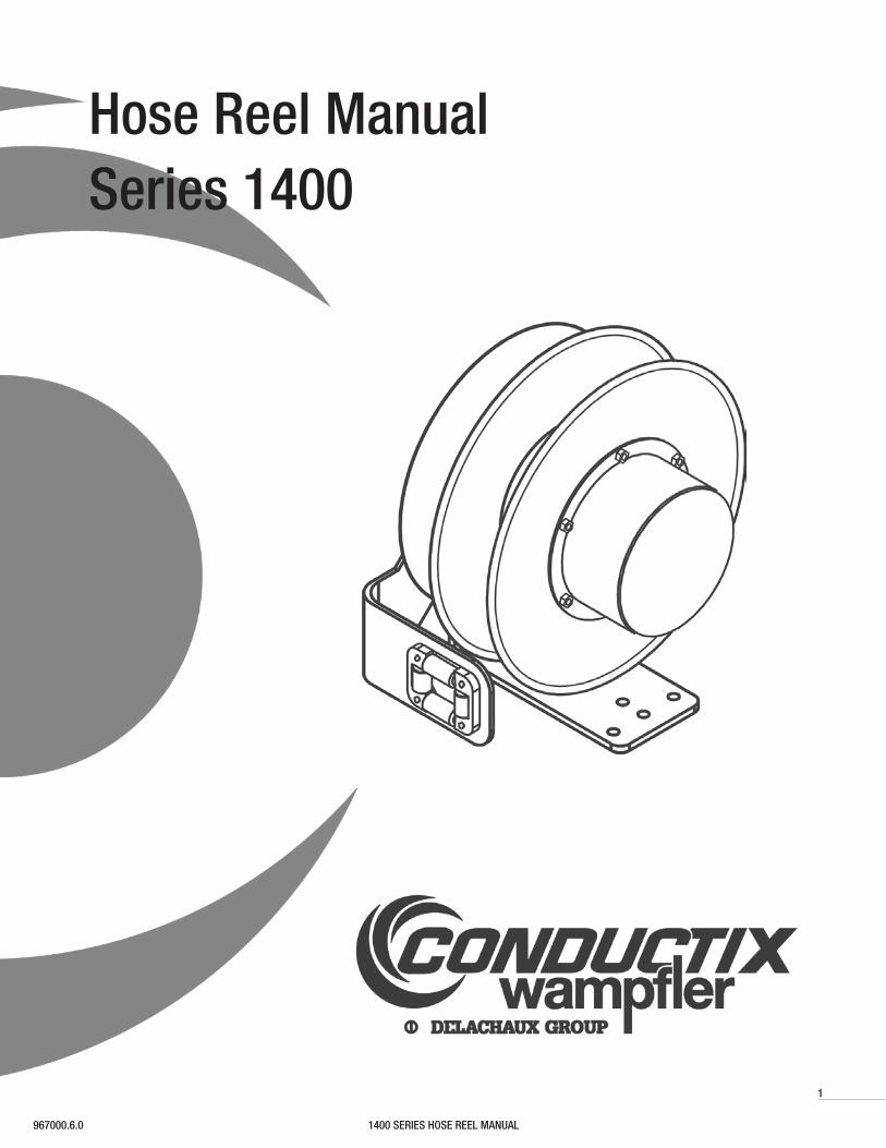
Hose Reel ManualSeries 1400
1400 SERIES HOSE REEL MANUAL 967000.6.0
2
The technical data and images which appear in this manual are for informational purposes only. NO WARRANTIES, EXPRESS OR IMPLIED, INCLUDING WARRANTIES
OF MERCHANTABILITY OR FITNESS FOR A PARTICULAR PURPOSE, ARE CREATED BY THE DESCRIPTIONS AND DEPICTIONS OF THE PRODUCTS SHOWN IN THIS
MANUAL. Conductix makes no warranty (and assumes no liability) as to function of equipment or operation of systems built according to customer design or of the ability of
any of its products to interface, operate or function with any portions of customer systems not provided by Conductix.
Seller agrees to repair or exchange the goods sold hereunder necessitated by reason of defective workmanship and material discovered and reported to Seller within one
year after shipment of such goods to Buyer.
Except where the nature of the defect is such that it is appropriate, in Seller’s judgment, to effect repairs on site, Seller’s obligation hereunder to remedy defects shall be
limited to repairing or replacing (at Seller’s option) FOB point of original shipment by Seller, any part returned to Seller at the risk and cost of Buyer. Defective parts replaced
by Seller shall become the property of Seller.
Seller shall only be obligated to make such repair or replacement if the goods have been used by Buyer only in service recommended by Seller and altered only as authorized
by Seller. Seller is not responsible for defects which arise from improper installation, neglect, or improper use or from normal wear and tear.
Additionally, Seller’s obligation shall be limited by the manufacturer’s warranty (and is not further warranted by Seller) for all parts procured from others according to
published data, specifications or performance information not designed by or for Seller.
Seller further agrees to replace or at Seller’s option to provide a refund of the sales price of any goods that do not conform to applicable specifications or which differ from
that agreed to be supplied which non-conformity is discovered and forthwith reported to Seller within thirty (30) days after shipment to the Buyer. Seller’s obligation to
replace or refund the purchase price for non-conforming goods shall arise once Buyer returns such goods FOB point of original shipment by Seller at the risk and cost of
Buyer. Goods replaced by Seller shall become the property of Seller.
There is no guarantee or warranty as to anything made or sold by Seller, or any services performed, except as to title and freedom from encumbrances and, except as herein
expressly stated and particularly, and without limiting the foregoing, there is no guarantee or warranty, express or implied, of merchantability or of fitness for any
particular purpose or against claim of infringement or the like.
Seller makes no warranty (and assumes no liability) as to function of equipment or operation of systems built to Buyer’s design or of the ability of any goods to interface,
operate or function with any portions of Buyer’s system not provided by Seller.
Seller’s liability on any claim, whether in contract, tort (including negligence), or otherwise, for any loss or damage arising out of, connected with, or resulting from the
manufacture, sale, delivery, resale, repair, replacement or use of any products or services shall in no case exceed the price paid for the product or services or any part
thereof which give rise to the claim. In no event shall Seller be liable for consequential, special, incidental or other damages, nor shall Seller be liable in respect of personal
injury or damage to property not the subject matter hereof unless attributable to gross misconduct of Seller, which shall mean an act or omission by Seller demonstrating
reckless disregard of the foreseeable consequences thereof.
Seller is not responsible for incorrect choice of models or where products are used in excess of their rated and recommended capacities and design functions or under
abnormal conditions. Seller assumes no liability for loss of time, damage or injuries to property or persons resulting from the use of Seller’s products. Buyer shall hold Seller
harmless from all liability, claims, suits and expenses in connection with loss or damage resulting from operation of products or utilization of services, respectively, of Seller
and shall defend any suit or action which might arise there from in Buyer’s name - provided that Seller shall have the right to elect to defend any such suit or action for the
account of Buyer. The foregoing shall be the exclusive remedies of the Buyer and all persons and entitles claiming through the Buyer.
CONDUCTIX INCORPORATED
1400 SERIES HOSE REEL MANUAL967000.6.0
3
1.0 Safety
1.1 Pressure Warnings
1.2 Operational Warnings
1.3 Maintenance Warnings
1.4 Specifications and Listings
1.5 Pressure and Temperature Rating
1.6 Labels and Markings
2.0 Installation
2.1 Application Types
2.2 Mounting
2.3 Roller Guides
2.4 Ratchet
2.5 Hose Installation and Replacement
2.6 Spring Tension Adjustment
3.0 Operation
4.0 Maintenance
4.1 Maintenance Warning
4.2 Lubrication
4.3 Inspections
4.4 Swivel Joint Assembly Replacement
4.5 Spring Motor Replacement
5.0 Troubleshooting
6.0 Replacement Parts
6.1 Part Descriptions
INDEX
RECORD
The catalog number of the reel and the serialnumber of the reel are required when ordering replace-ment parts or discussing the reel with the factory. Please record this information now in the spaces provided below.
CATALOG NO. OF REEL:
SERIAL NO:
DATE INSTALLED:
1400 SERIES HOSE REEL MANUAL 967000.6.0
4
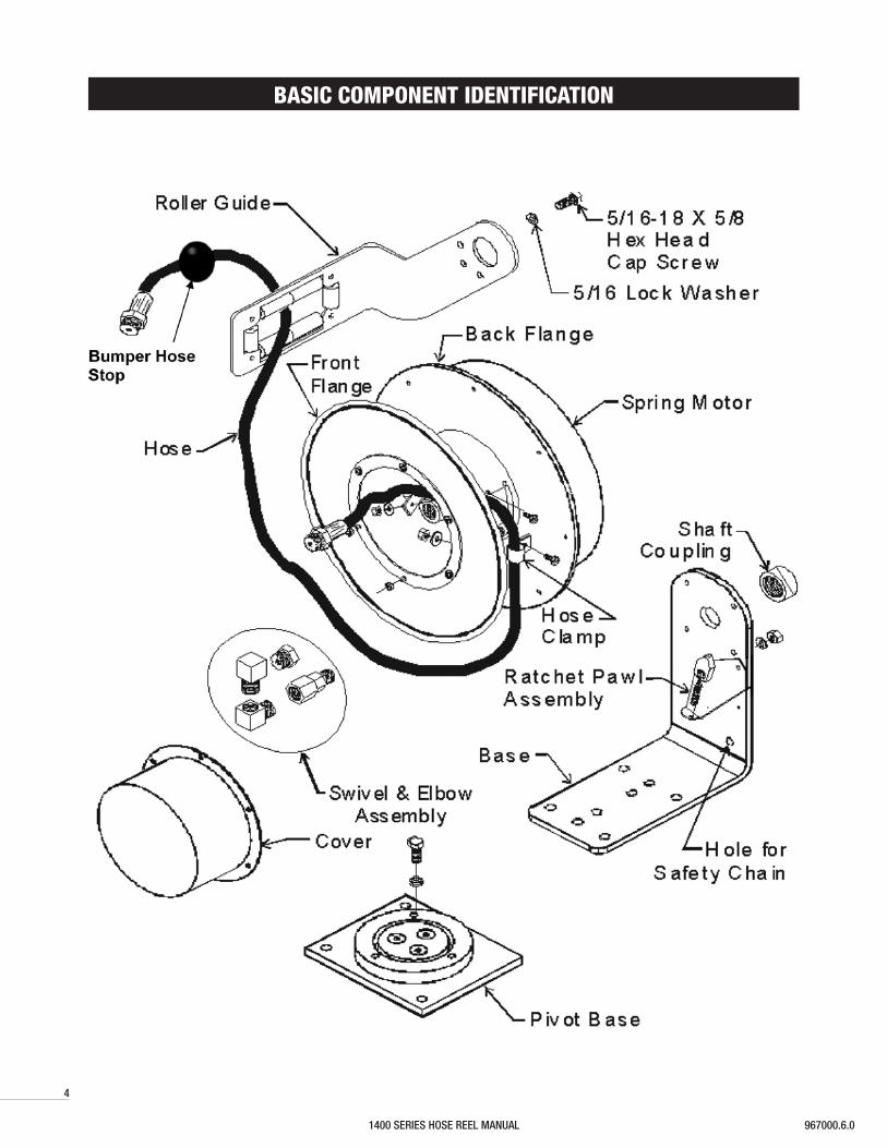
BASIC COMPONENT IDENTIFICATION
1400 SERIES HOSE REEL MANUAL967000.6.0
5
1.0 SAFETY
1.1 Pressure Warnings
1.1.1 This equipment should be properly installed before use in accordance with local codes and ordinances.
1.1.2 The pressure from the hose reel should be disconnected from the hose reel before any service functions are performed.
1.1.3 This hose reel must not be used for pressure greater than the rating listed on the label. See Section 1.5 for Pressure & Temperature Ratings.
1.2 Operational Warnings
1.2.1 Exercise care when handling the hose reel during normal operation. This hose reel has a rotating spool powered by springs under tension.
1.2.2 Do not use hose different from that for which the reel is intended. Changes in diameter, weight per foot, length of hose or flexibility will affect the operation of the reel.
1.2.3 Mounting hardware and fasteners should be installed to maintain tightness under vibration and checked periodically to ensure tightness.
1.2.4 Overhead installation mountings should be such that the reel is not supported by bolts in tension. A safety chain or cable is strongly recommended to minimize
damage and/or possible injury in the event of mounting failure.
1.3 Maintenance Warnings
1.3.1 WARNING: Modification of this equipment may cause excessive wear and will void the warranty. Contact the manufacturer regarding changes or modifications of
equipment which could affect reliability or safety.
1.3.2 DO NOT DISASSEMBLE THE SPRING MOTOR FOR ANY REASON. Serious personal injury could result. This hose reel is equipped with springs under tension.
Contact the factory for assistance.
US: 1-800-452-0052
Canada: 1-800-667-2487
1.4 Specifications & Listings
1.4.1 1400 Series Hose Reel products are not certified or listed by any independent certifying or regulatory body.
1.4.2 The following specifications apply to all 1400 Series Hose Reels:
1.4.2.1 1400 Series Hose Reels are intended for industrial use and are provided with permanent mounting means.
1.4.2.2 1400 Series Hose Reels provide a 1/2 inch NPT female pipe thread for the stationary connection.
1.4.2.3 1400 Series Hose Reel Spring Motors are weather-tight and self-contained.
1.5 Pressure & Temperature Rating
1.5.1. All Conductix 1400 Series Hose Reels with or without hose installed are rated at 300 P.S.I. Reels should not be used at pressures greater than the rating of the hose.
1.5.2 Installed hose is suitable for delivery of both air & water.
1.5.3 Operational temperature ranges for hose reels with hose delivering air are between -20°F through +150°F. Operational temperature ranges for hose reels with hose
delivering water are between +32°F through +150°F. Hose Reels should not be used at temperatures below or above the rating of the hose.
1.5.4 The operational rating of a reel not equipped with hose is determined by the capacity of the installed hose. The pressure rating of the reel without hose must not be
greater than 300 psi. Variations in the OD of higher rated hose will affect the operational capacity of the reel.
1.6 Labels & Markings
1.6.1 Hose Reels with and without Hose
1.6.1.1 The marking of the hose reel provided with or without hose includes the following:
1.6.1.1.1 The label on the frame includes the Conductix name and logo, the product catalog number, the individual product serial number, PSI rating, description of the reel,
what type and length of hose intended for use on the reel.
1.6.1.1.2 The maximum pressure rating for every hose reel supplied without hose is marked on the Conductix Identification Label. Actual rating is determined by the
installed hose and is not to exceed the indicated maximum rating. The pressure rating of the hose installed on reels provided without hose must be marked on the
label upon installation.
1400 SERIES HOSE REEL MANUAL 967000.6.0
6
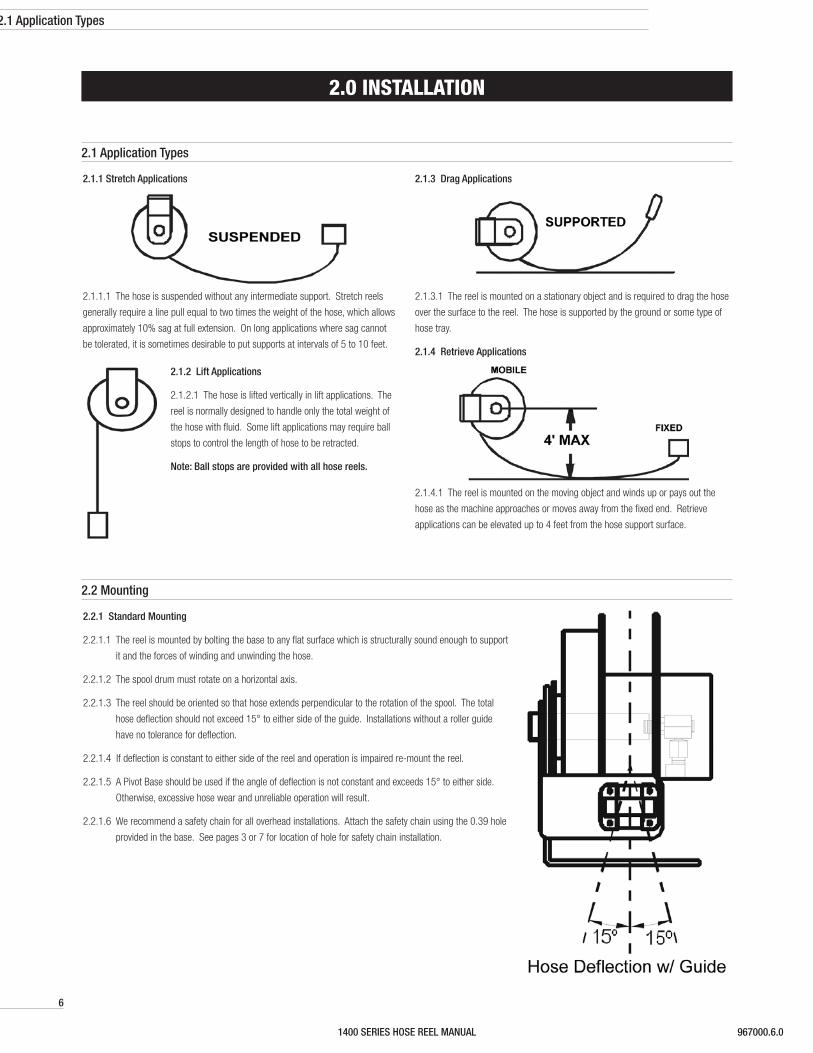
2.1.1 Stretch Applications
2.1.1.1 The hose is suspended without any intermediate support. Stretch reels
generally require a line pull equal to two times the weight of the hose, which allows
approximately 10% sag at full extension. On long applications where sag cannot
be tolerated, it is sometimes desirable to put supports at intervals of 5 to 10 feet.
2.1.2 Lift Applications
2.1.2.1 The hose is lifted vertically in lift applications. The
reel is normally designed to handle only the total weight of
the hose with fluid. Some lift applications may require ball
stops to control the length of hose to be retracted.
Note: Ball stops are provided with all hose reels.
2.1.3 Drag Applications
2.1.3.1 The reel is mounted on a stationary object and is required to drag the hose
over the surface to the reel. The hose is supported by the ground or some type of
hose tray.
2.1.4 Retrieve Applications
2.1.4.1 The reel is mounted on the moving object and winds up or pays out the
hose as the machine approaches or moves away from the fixed end. Retrieve
applications can be elevated up to 4 feet from the hose support surface.
2.2.1 Standard Mounting
2.2.1.1 The reel is mounted by bolting the base to any flat surface which is structurally sound enough to support
it and the forces of winding and unwinding the hose.
2.2.1.2 The spool drum must rotate on a horizontal axis.
2.2.1.3 The reel should be oriented so that hose extends perpendicular to the rotation of the spool. The total
hose deflection should not exceed 15° to either side of the guide. Installations without a roller guide
have no tolerance for deflection.
2.2.1.4 If deflection is constant to either side of the reel and operation is impaired re-mount the reel.
2.2.1.5 A Pivot Base should be used if the angle of deflection is not constant and exceeds 15° to either side.
Otherwise, excessive hose wear and unreliable operation will result.
2.2.1.6 We recommend a safety chain for all overhead installations. Attach the safety chain using the 0.39 hole
provided in the base. See pages 3 or 7 for location of hole for safety chain installation.
2.0 INSTALLATION
2.1 Application Types
2.1 Application Types
2.2 Mounting
1400 SERIES HOSE REEL MANUAL967000.6.0
7
2.2.2 Pivot Base Mounting
2.2.2.1 All 1400 Series Hose Reels can be furnished with a pivot base to allow the
reel to rotate and keep the extended hose perpendicular to the application.
2.2.2.2 The PVB Pivot Base has the ability to rotate up to 345°. Travel can be
limited to 90°, 180°, or 270° by installing an additional roll pin in the
appropriate available hole. This Pivot Base is not suitable for applications
requiring continuous rotation.
2.2.2.3 A pivot base is required in carousel or loop-track applications.
2.2.2.4 When a pivot base is used the reel must be mounted horizontally (“ceiling”
or “floor” mounted).
2.2.2.5 The Roller Guide should be mounted to require the hose to travel
perpendicular to the axis of rotation. This will guard against the hose
twisting and ensure effective swivel action from the pivot base.
2.2.2.6 Selection of mounting holes should be such that spool center is in line
with center point of pivot base. Note: PA, PB or PC can be found in the
description of the Conductix Label.
2.0 INSTALLATION
2.3.1 All 1400 Series Hose Reel units are equipped with a roller guide (PR87). The
guide’s function is to center the hose on the spool and to help the reel wrap
hose more evenly.
2.3.2 The guide must be located and secured prior to making any hose
connections.
2.3.3 The hose should not bear against either of the spool flanges during winding
as this will tend to inhibit level winding of the hose.
2.3.4 The guide should be secured at the best of twelve possible positions so that
a minimum change of direction occurs at the guide; otherwise, hose life will
be reduced and reel operation will be impaired. The illustration shows four of
the twelve possible positions.
2.3.4.1 Mount the guide to the reel over the entrance coupling on the frame.
Secure using the provided 5/16-18 hex head cap screw, including the
spring-type lock washer.
-H
2.3 Roller Guides
1400 SERIES HOSE REEL MANUAL 967000.6.0
8
2.0 INSTALLATION
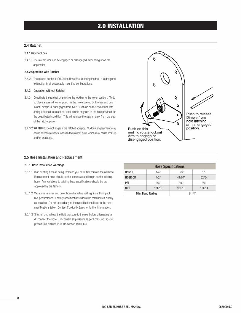
2.4.1 Ratchet Lock
2.4.1.1 The ratchet lock can be engaged or disengaged, depending upon the
application.
2.4.2 Operation with Ratchet
2.4.2.1 The ratchet on the 1400 Series Hose Reel is spring loaded. It is designed
to function in all acceptable mounting configurations.
2.4.3 Operation without Ratchet
2.4.3.1 Deactivate the ratchet by pivoting the lockbar to the lower position. To do
so place a screwdriver or punch in the hole covered by the bar and push
in until dimple is disengaged from hole. Push up on the end of bar with
spring attached to rotate bar until dimple engages in the hole provided for
the deactivated condition. This will remove the ratchet pawl from the path
of the ratchet plate.
2.4.3.2 WARNING: Do not engage the ratchet abruptly. Sudden engagement may
cause excessive shock loads to the ratchet pawl which may cause lock-up
and/or breakage.
2.5.1 Hose Installation Warnings
2.5.1.1 If an existing hose is being replaced you must first remove the old hose.
Replacement hose should be the same size and length as the existing
hose. Any variations to existing hose specifications should be pre-
approved by the factory.
2.5.1.2 Variations in inner and outer hose diameters will significantly impact
reel performance. Factory specifications should be matched as closely
as possible. Do not exceed any of the specifications listed in the hose
specifications table. Contact Conductix Sales for further information.
2.5.1.3 Shut-off and relieve the fluid pressure to the reel before attempting to
disconnect the hose. Disconnect all pressure as per Lock-Out/Tag-Out
procedures outlined in OSHA section 1910.147.
Hose SpecificationsHose ID 1/4” 3/8” 1/2
HOSE OD 1/2” 41/64” 52/64
PSI 300 300 300
NPT 1/4-18 3/8-18 1/4-14
Min. Bend Radius 6 1/4”
2.4 Ratchet
2.5 Hose Installation and Replacement
1400 SERIES HOSE REEL MANUAL967000.6.0
9
2.0 INSTALLATION
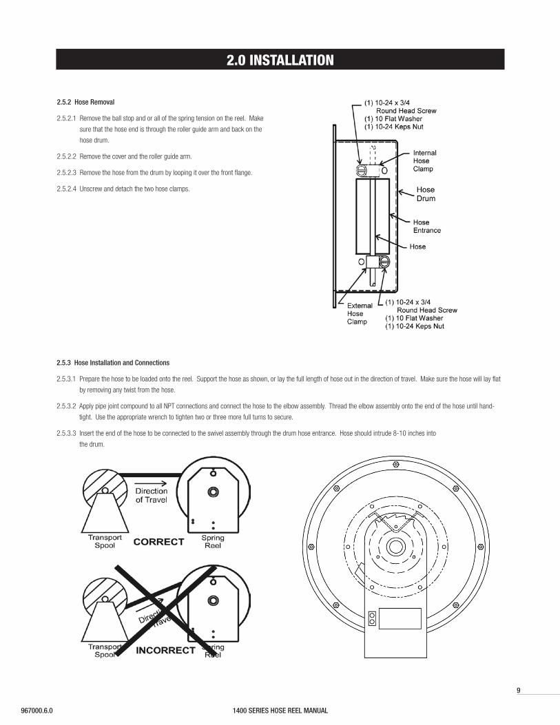
2.5.2 Hose Removal
2.5.2.1 Remove the ball stop and or all of the spring tension on the reel. Make
sure that the hose end is through the roller guide arm and back on the
hose drum.
2.5.2.2 Remove the cover and the roller guide arm.
2.5.2.3 Remove the hose from the drum by looping it over the front flange.
2.5.2.4 Unscrew and detach the two hose clamps.
2.5.3 Hose Installation and Connections
2.5.3.1 Prepare the hose to be loaded onto the reel. Support the hose as shown, or lay the full length of hose out in the direction of travel. Make sure the hose will lay flat
by removing any twist from the hose.
2.5.3.2 Apply pipe joint compound to all NPT connections and connect the hose to the elbow assembly. Thread the elbow assembly onto the end of the hose until hand-
tight. Use the appropriate wrench to tighten two or three more full turns to secure.
2.5.3.3 Insert the end of the hose to be connected to the swivel assembly through the drum hose entrance. Hose should intrude 8-10 inches into
the drum.
1400 SERIES HOSE REEL MANUAL 967000.6.0
10
2.0 INSTALLATION
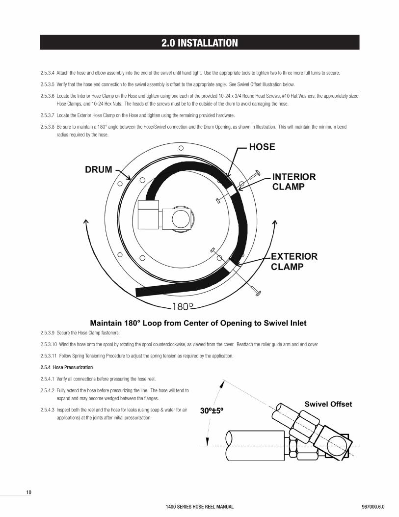
2.5.3.4 Attach the hose and elbow assembly into the end of the swivel until hand tight. Use the appropriate tools to tighten two to three more full turns to secure.
2.5.3.5 Verify that the hose end connection to the swivel assembly is offset to the appropriate angle. See Swivel Offset Illustration below.
2.5.3.6 Locate the Interior Hose Clamp on the Hose and tighten using one each of the provided 10-24 x 3/4 Round Head Screws, #10 Flat Washers, the appropriately sized
Hose Clamps, and 10-24 Hex Nuts. The heads of the screws must be to the outside of the drum to avoid damaging the hose.
2.5.3.7 Locate the Exterior Hose Clamp on the Hose and tighten using the remaining provided hardware.
2.5.3.8 Be sure to maintain a 180° angle between the Hose/Swivel connection and the Drum Opening, as shown in Illustration. This will maintain the minimum bend
radius required by the hose.
2.5.3.9 Secure the Hose Clamp fasteners.
2.5.3.10 Wind the hose onto the spool by rotating the spool counterclockwise, as viewed from the cover. Reattach the roller guide arm and end cover
2.5.3.11 Follow Spring Tensioning Procedure to adjust the spring tension as required by the application.
2.5.4 Hose Pressurization
2.5.4.1 Verify all connections before pressuring the hose reel.
2.5.4.2 Fully extend the hose before pressurizing the line. The hose will tend to
expand and may become wedged between the flanges.
2.5.4.3 Inspect both the reel and the hose for leaks (using soap & water for air
applications) at the joints after initial pressurization.
1400 SERIES HOSE REEL MANUAL967000.6.0
11
2.0 INSTALLATION
2.6.1 Spring Tension Warnings
2.6.1.1 This adjustment may require mechanical assistance in more demanding applications and installations.
2.6.1.2 WARNING: Do not allow hose to retract without restraining the retraction speed. Walk the hose back to the reel during the spring tension adjusting process.
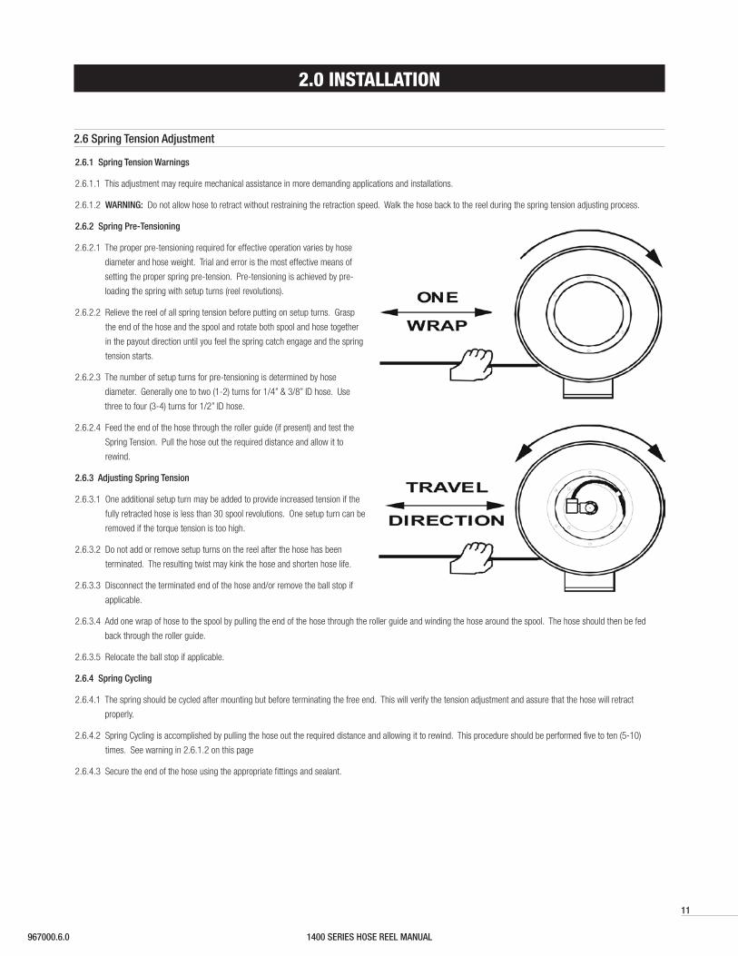
2.6.2 Spring Pre-Tensioning
2.6.2.1 The proper pre-tensioning required for effective operation varies by hose
diameter and hose weight. Trial and error is the most effective means of
setting the proper spring pre-tension. Pre-tensioning is achieved by pre-
loading the spring with setup turns (reel revolutions).
2.6.2.2 Relieve the reel of all spring tension before putting on setup turns. Grasp
the end of the hose and the spool and rotate both spool and hose together
in the payout direction until you feel the spring catch engage and the spring
tension starts.
2.6.2.3 The number of setup turns for pre-tensioning is determined by hose
diameter. Generally one to two (1-2) turns for 1/4” & 3/8” ID hose. Use
three to four (3-4) turns for 1/2” ID hose.
2.6.2.4 Feed the end of the hose through the roller guide (if present) and test the
Spring Tension. Pull the hose out the required distance and allow it to
rewind.
2.6.3 Adjusting Spring Tension
2.6.3.1 One additional setup turn may be added to provide increased tension if the
fully retracted hose is less than 30 spool revolutions. One setup turn can be
removed if the torque tension is too high.
2.6.3.2 Do not add or remove setup turns on the reel after the hose has been
terminated. The resulting twist may kink the hose and shorten hose life.
2.6.3.3 Disconnect the terminated end of the hose and/or remove the ball stop if
applicable.
2.6.3.4 Add one wrap of hose to the spool by pulling the end of the hose through the roller guide and winding the hose around the spool. The hose should then be fed
back through the roller guide.
2.6.3.5 Relocate the ball stop if applicable.
2.6.4 Spring Cycling
2.6.4.1 The spring should be cycled after mounting but before terminating the free end. This will verify the tension adjustment and assure that the hose will retract
properly.
2.6.4.2 Spring Cycling is accomplished by pulling the hose out the required distance and allowing it to rewind. This procedure should be performed five to ten (5-10)
times. See warning in 2.6.1.2 on this page
2.6.4.3 Secure the end of the hose using the appropriate fittings and sealant.
2.6 Spring Tension Adjustment
1400 SERIES HOSE REEL MANUAL 967000.6.0
12
3.0 OPERATION
3.1 Do not exceed the pressure or temperature rating of the hose. Do not exceed the pressure or temperature rating of the reel. Pressure and temperature above the
rated capacity could cause damage to equipment and personal injury could result.
3.2 Operate the reel within the hose size, length and spring tensioning limits for which it was intended.
3.2.1 Note: Two wraps of hose should remain on the reel at maximum extension to avoid excessive tension on the hose clamps.
3.2.2 The spring should not be wound to the last two turns at maximum payout to avoid over-stressing the spring, thus reducing spring life or damaging the reel. See
Section 2.6.3.1 for details.
3.3 Keep the reel and hose clean to avoid excessive wear and damage.
3.4 Arrange for maintenance service if damage is found on the hose or reel.
3.5 Hose should be fully retracted when not in service to maximize spring life.
4.0 MAINTENANCE
4.4.1 The swivel joint should be replaced, not rebuilt, if it becomes damaged.
4.4.2 Follow steps 2.5.2.1 through 2.5.3.4 to disconnect the hose and elbow assembly from the reel.
4.4.3 Separate the swivel joint from the shaft and dispose of the damaged swivel joint.
4.4.4 Re-assemble the reel as outlined in Section 2.5.3: Hose Installation using the replacement swivel joint.
4.1.1 Be sure all pressure is off for maintenance.
4.1.2 Follow lock-out/tag-out procedures as outlined in OSHA section 1910.147 where appropriate.
4.1 Maintenance Warnings
4.2 Lubrication
4.2.1 All springs and bearings are lubricated for life at the factory. Additional lubrication should not be required.
4.3 Inspections
4.3.1 Periodically check the reel for any loose or missing fasteners. Tighten or replace as necessary.
4.4 Swivel Joint Assembly Replacement
1400 SERIES HOSE REEL MANUAL967000.6.0
13
4.0 MAINTENANCE
4.5.1 Spring Motor Warnings
4.5.1.1 CAUTION: Do not open the spring motor or personal injury may result.
4.5.1.2 The spring replacement process is determined by the spring configuration and cannot be performed in the field. The entire spring motor must be replaced as a
unit.
4.5.1.3 For further instructions, consult the factory.
In the USA call: 1-800-452-0052.
In Canada call: 1-800-667-2487.
4.5.2 Spring Motor Life
4.5.2.1 Spring life is determined by duty cycle and application requirements. Spring life can vary depending on operating environment, application range, and duty cycle.
Actual performance and maintenance scheduling can only be determined by individual factors in the application.
4.5.3 Spring Motor Removal & Replacement
4.5.3.1 Relieve all gas/fluid pressure to the reel before beginning any maintenance or service.
4.5.3.2 Disconnect the terminated end of the hose.
4.5.3.3 Follow the steps listed in Section
4.5.3.4 Remove the elbow assembly from the shaft by using the appropriately sized wrench.
4.5.3.5 Remove the shaft coupling (PR47-H).
4.5.3.6 Remove the spring motor (PR89-H) by unscrewing the shaft from the mounting base (PR04A-2).
4.5.3.7 Remove packing material from the replacement spring motor. Attach the replacement spring motor to the mounting base.
4.5.3.8 Re-assemble the spring reel by following the previous steps in reverse order. Be sure to engage the ratchet mechanism as outlined in Section 2.4.
4.5.3.9 Adjust spring tension by following the procedure in section 2.6.
4.5 Spring Motor Replacement
1400 SERIES HOSE REEL MANUAL 967000.6.0
14
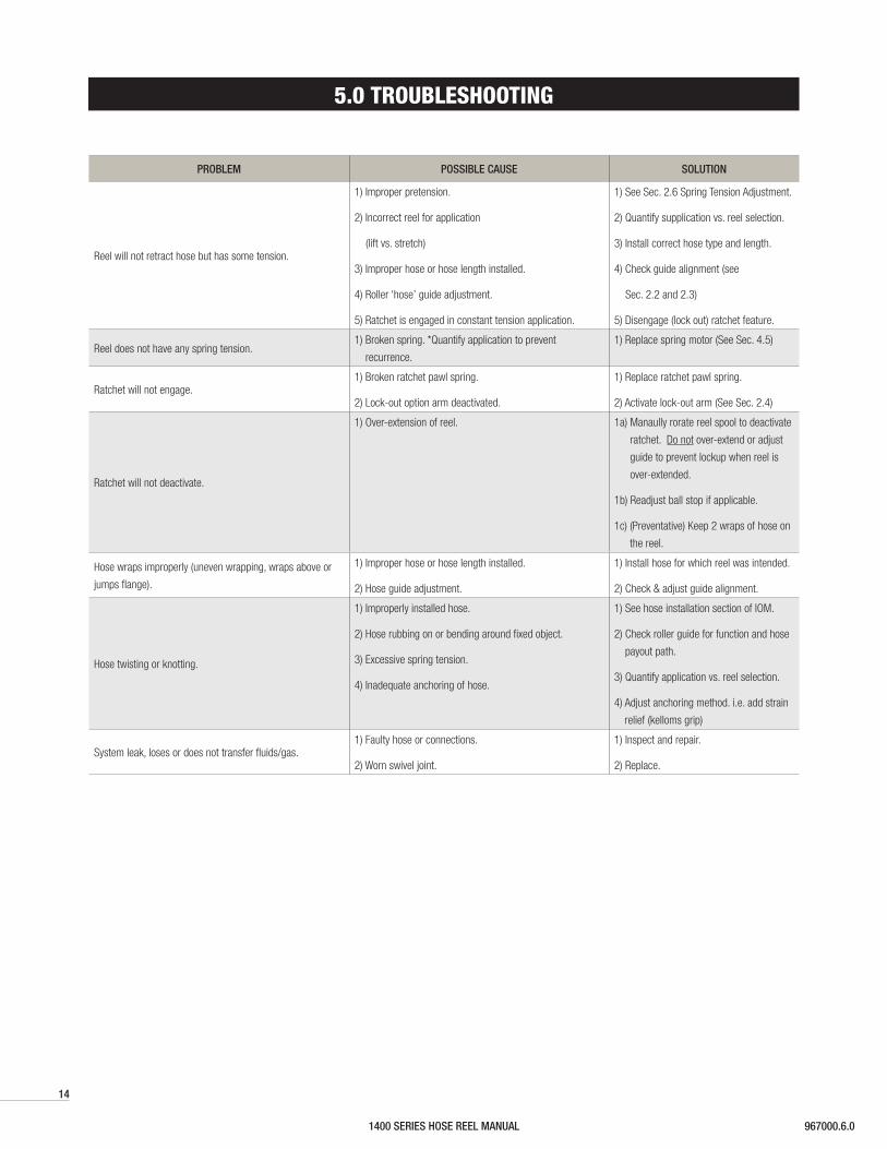
5.0 TROUBLESHOOTING
PROBLEM POSSIBLE CAUSE SOLUTION
Reel will not retract hose but has some tension.
1) Improper pretension.
2) Incorrect reel for application
(lift vs. stretch)
3) Improper hose or hose length installed.
4) Roller ‘hose’ guide adjustment.
5) Ratchet is engaged in constant tension application.
1) See Sec. 2.6 Spring Tension Adjustment.
2) Quantify supplication vs. reel selection.
3) Install correct hose type and length.
4) Check guide alignment (see
Sec. 2.2 and 2.3)
5) Disengage (lock out) ratchet feature.
Reel does not have any spring tension.1) Broken spring. *Quantify application to prevent
recurrence.
1) Replace spring motor (See Sec. 4.5)
Ratchet will not engage.1) Broken ratchet pawl spring.
2) Lock-out option arm deactivated.
1) Replace ratchet pawl spring.
2) Activate lock-out arm (See Sec. 2.4)
Ratchet will not deactivate.
1) Over-extension of reel. 1a) Manaully rorate reel spool to deactivate
ratchet. Do not over-extend or adjust
guide to prevent lockup when reel is
over-extended.
1b) Readjust ball stop if applicable.
1c) (Preventative) Keep 2 wraps of hose on
the reel.
Hose wraps improperly (uneven wrapping, wraps above or
jumps flange).
1) Improper hose or hose length installed.
2) Hose guide adjustment.
1) Install hose for which reel was intended.
2) Check & adjust guide alignment.
Hose twisting or knotting.
1) Improperly installed hose.
2) Hose rubbing on or bending around fixed object.
3) Excessive spring tension.
4) Inadequate anchoring of hose.
1) See hose installation section of IOM.
2) Check roller guide for function and hose
payout path.
3) Quantify application vs. reel selection.
4) Adjust anchoring method. i.e. add strain
relief (kelloms grip)
System leak, loses or does not transfer fluids/gas.1) Faulty hose or connections.
2) Worn swivel joint.
1) Inspect and repair.
2) Replace.
1400 SERIES HOSE REEL MANUAL967000.6.0
15
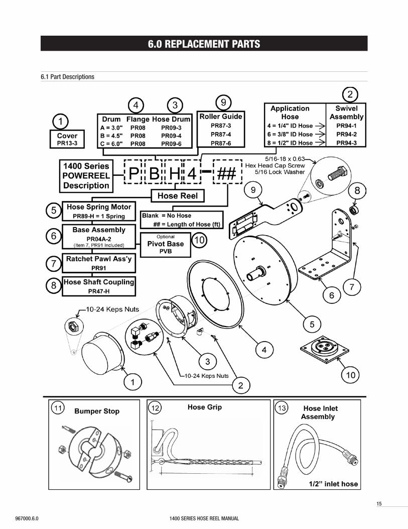
6.0 REPLACEMENT PARTS
6.1 Part Descriptions
1400 SERIES HOSE REEL MANUAL 967000.6.0
Contact us for our Global Sales Offices
www.conductix.us
USA / LATIN AMERICA
10102 F Street
Omaha, NE 68127
Customer Support
Phone +1-800-521-4888
Phone +1-402-339-9300
Fax +1-402-339-9627
CANADA
1435 Norjohn Court
Unit 5
Burlington, ON L7L 0E6
Customer Support
Phone +1-800-667-2487
Phone +1-450-565-9900
Fax +1-450-851-8591
MÉXICO
Calle Treviño 983-C
Zona Centro
Apodaca, NL México 66600
Customer Support
Phone (+52 81) 1090 9519
(+52 81) 1090 9025
(+52 81) 1090 9013
Fax (+52 81) 1090 9014
BRAZIL
Rua Luiz Pionti, 110
Vila Progresso
Itu, São Paulo, Brasil
CEP: 13313-534
Customer Support
Phone (+55 11) 4813 7330
Fax (+55 11) 4813 7357
© C
ondu
ctix-
Wam
pfler
| 20
17 |
Subj
ect t
o Te
chni
cal M
odifi
catio
ns W
ithou
t Prio
r Not
ice
16
Recommended