HOMEBREW QSK CW STATION AT W6JL
USING PHASING RECEIVER WITH “TAYLOE” FRONT END
AND AA0ZZ Si570 VFO AS LOCAL OSCILLATOR.
14 July 2011
Updated 4 August 2011
Updated 17 August 2011
Updated 20 August 2011
Homebrew station at W6JL. 550W output, using a keyed AD9850 DDS VFO.
HB amplifier is one I built in 1972 and has 40 dB of power gain
(10,000). (Homebrew rigs last forever :o)). The all band phasing
receiver uses a double-balanced version of the Tayloe (also known as
a Quadrature Sampling Detector, Q.S.D.) front end. The receiver is
contained in the boxes shown. The Tayloe replaces the lossy dual
ring balanced mixers, quadrature high level L.O's; power splitter, LC
diplexers, and post mixer attenuators used in previous phasing
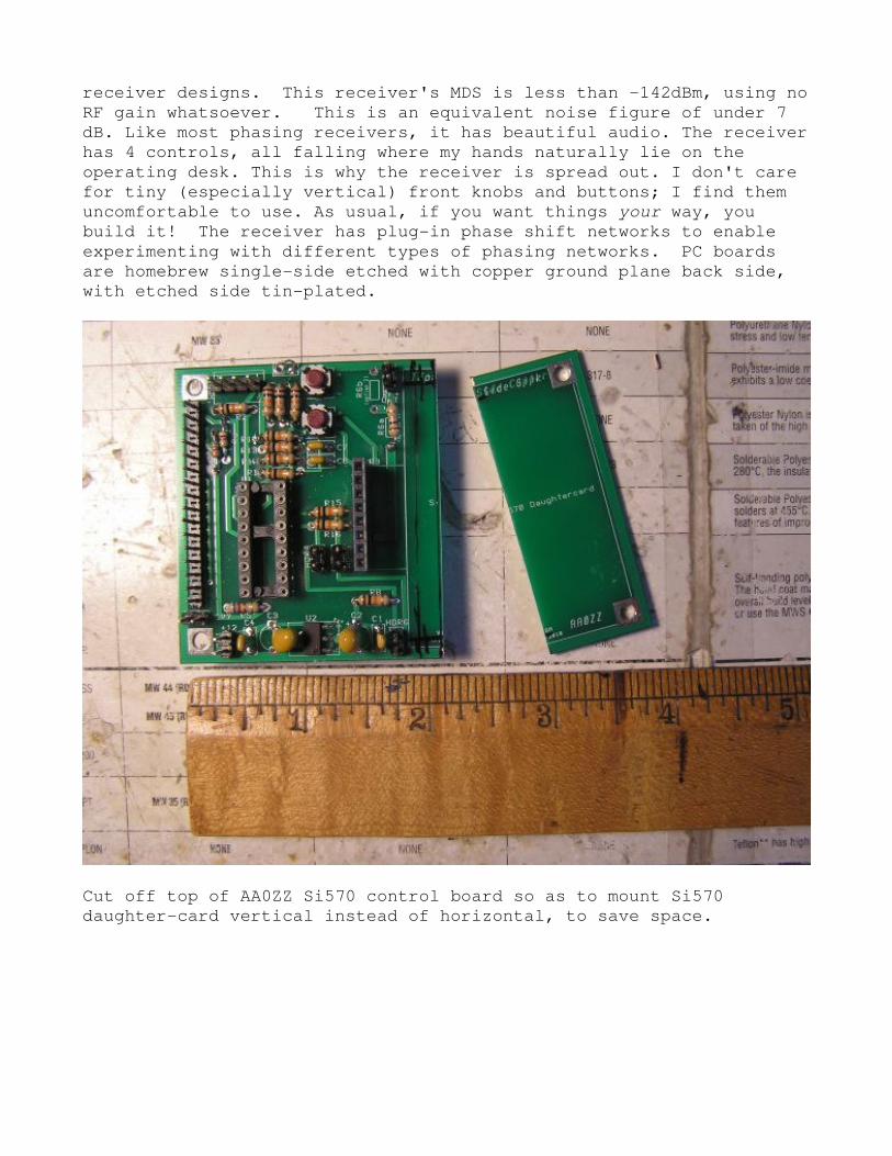
receiver designs. This receiver's MDS is less than -142dBm, using no
RF gain whatsoever. This is an equivalent noise figure of under 7
dB. Like most phasing receivers, it has beautiful audio. The receiver
has 4 controls, all falling where my hands naturally lie on the
operating desk. This is why the receiver is spread out. I don't care
for tiny (especially vertical) front knobs and buttons; I find them
uncomfortable to use. As usual, if you want things your way, you
build it! The receiver has plug-in phase shift networks to enable
experimenting with different types of phasing networks. PC boards
are homebrew single-side etched with copper ground plane back side,
with etched side tin-plated.
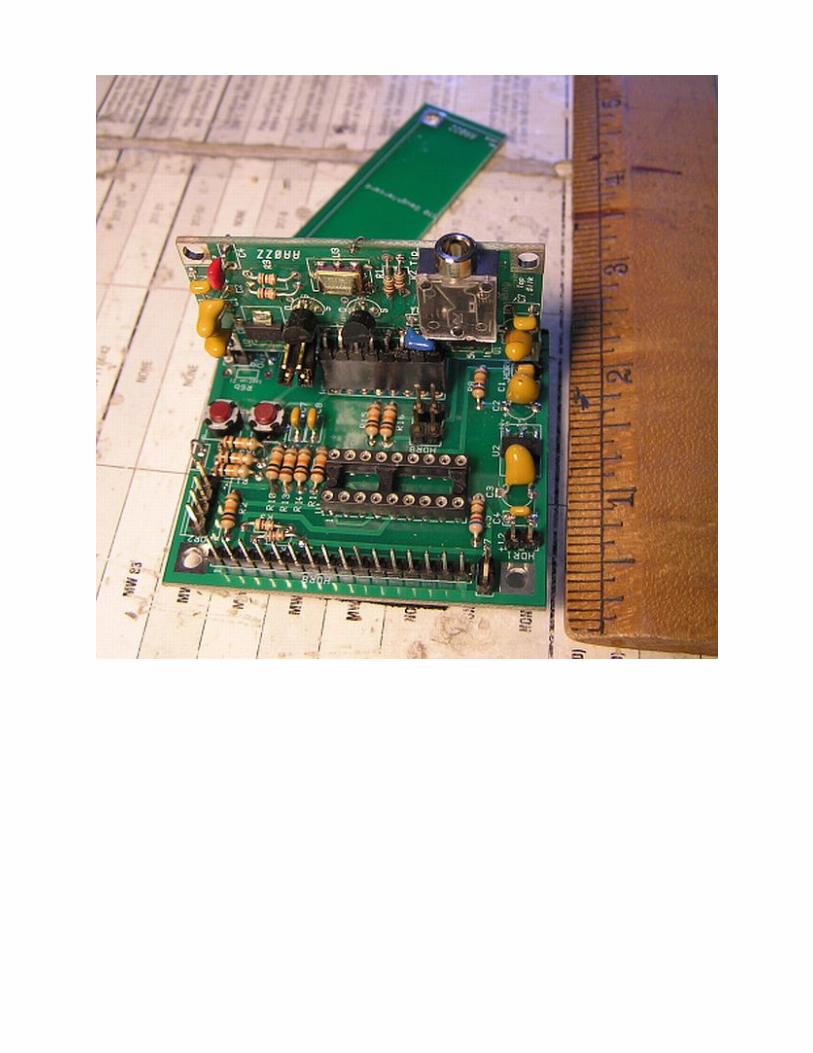
Cut off top of AA0ZZ Si570 control board so as to mount Si570
daughter-card vertical instead of horizontal, to save space.
Si570 L.O. interior. This is built from Craig, AA0ZZ's Si570 VFO
board, see http://cbjohn.com/aa0zz/index.html
http://www.kangaus.com/si570_project.htm
Craig's board, making it a
in this homebrew enclosure. I
code slightly, to put my callsign on the LCD and format the frequency
readout to my liking. The Si570 has much lower spurs and phase noise
than a DDS, and a much higher maximum frequency, making it ideal for
a double-balanced Tayloe receiver using an L.O. Running at 4X the
signal frequency. Copper
build of most any size and shape, and make excellent RF shielded
enclosures. Placing the rotary encoder tuning on the left side makes
it easier to tune in actual use
you homebrew, you have complete control over the electronic features
and physical arrangement of your rig. You do not have to settle for
what some other designer thought was best for you, i
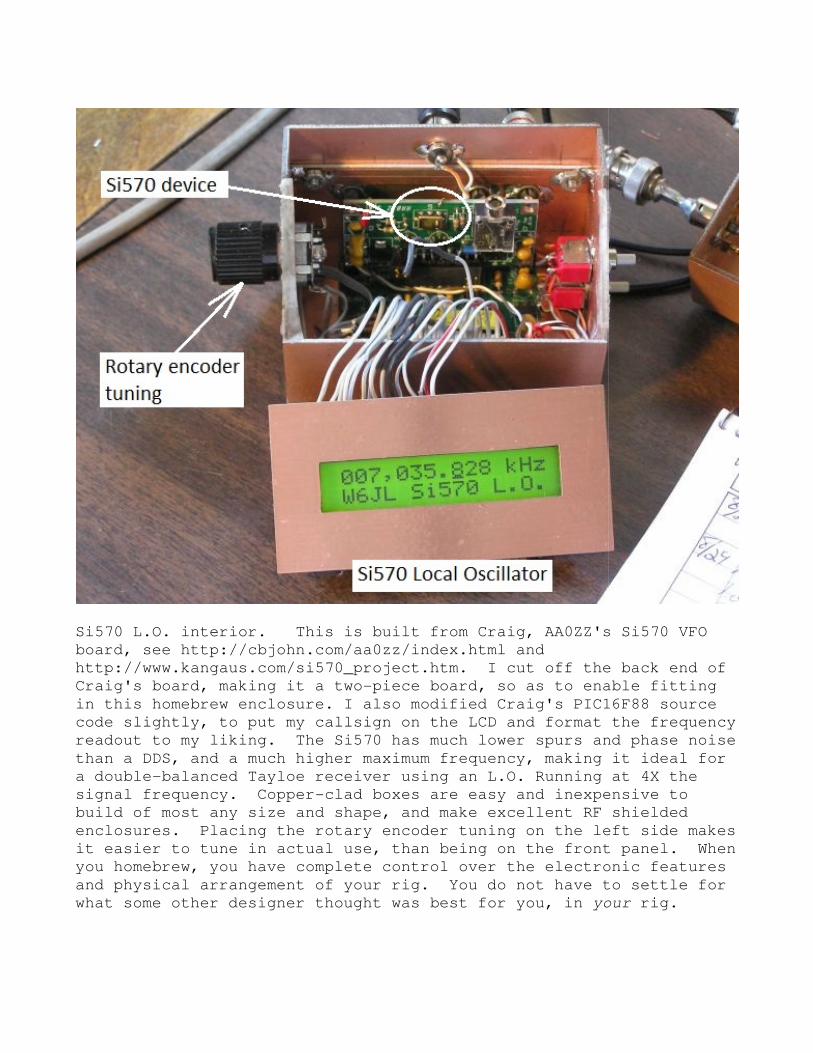
Si570 L.O. interior. This is built from Craig, AA0ZZ's Si570 VFO
ohn.com/aa0zz/index.html and
http://www.kangaus.com/si570_project.htm. I cut off the back end of
it a two-piece board, so as to enable fitting
in this homebrew enclosure. I also modified Craig's PIC16
code slightly, to put my callsign on the LCD and format the frequency
readout to my liking. The Si570 has much lower spurs and phase noise
than a DDS, and a much higher maximum frequency, making it ideal for
ced Tayloe receiver using an L.O. Running at 4X the
signal frequency. Copper-clad boxes are easy and inexpensive to
build of most any size and shape, and make excellent RF shielded
enclosures. Placing the rotary encoder tuning on the left side makes
asier to tune in actual use, than being on the front panel
you homebrew, you have complete control over the electronic features
and physical arrangement of your rig. You do not have to settle for
what some other designer thought was best for you, in your
Si570 L.O. interior. This is built from Craig, AA0ZZ's Si570 VFO
I cut off the back end of
so as to enable fitting
modified Craig's PIC16F88 source
code slightly, to put my callsign on the LCD and format the frequency
readout to my liking. The Si570 has much lower spurs and phase noise
than a DDS, and a much higher maximum frequency, making it ideal for
ced Tayloe receiver using an L.O. Running at 4X the
clad boxes are easy and inexpensive to
build of most any size and shape, and make excellent RF shielded
enclosures. Placing the rotary encoder tuning on the left side makes
on the front panel. When
you homebrew, you have complete control over the electronic features
and physical arrangement of your rig. You do not have to settle for
your rig.
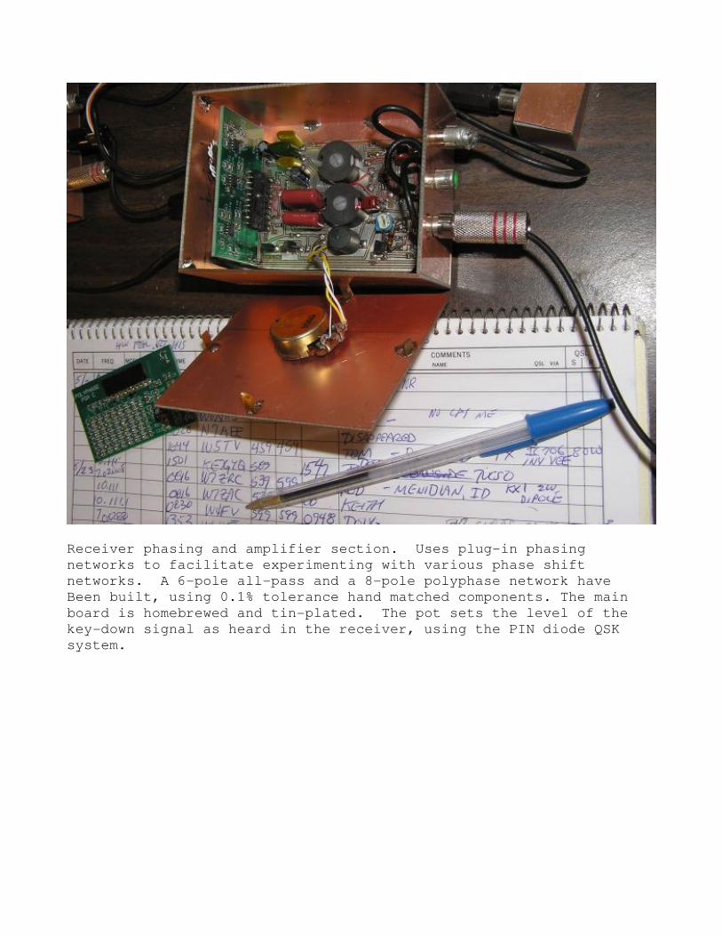
Receiver phasing and amplifier section. Uses plug-in phasing
networks to facilitate experimenting with various phase shift
networks. A 6-pole all-pass and a 8-pole polyphase network have
Been built, using 0.1% tolerance hand matched components. The main
board is homebrewed and tin-plated. The pot sets the level of the
key-down signal as heard in the receiver, using the PIN diode QSK
system.
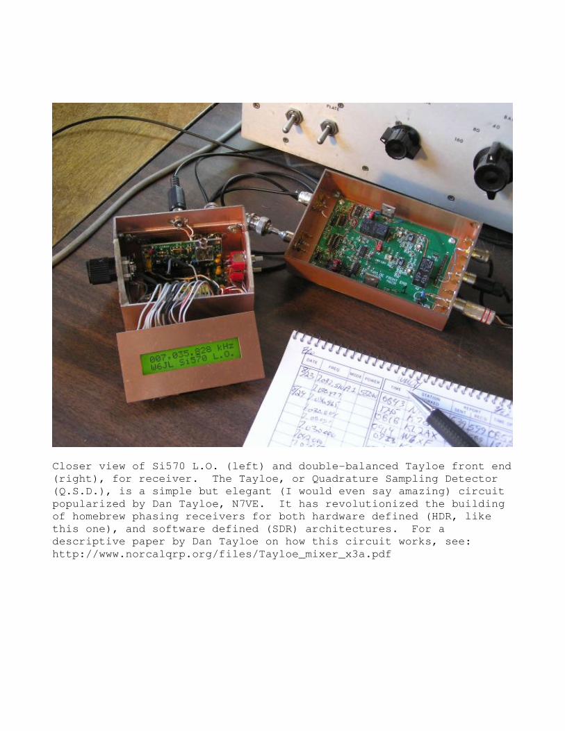
Closer view of Si570 L.O. (left) and double
(right), for receiver. The Tayloe, or Quadrature Sampling Detector
(Q.S.D.), is a simple but elegant (I would even say amazing) circuit
popularized by Dan Tayloe, N7VE. It has revolutionized the building
of homebrew phasing receivers for both hardware defined (HDR, like
this one), and software defined (SDR) architectures. For a
descriptive paper by Dan Tayloe
http://www.norcalqrp.org/files/Tayloe_mixer_x3a.pdf
Closer view of Si570 L.O. (left) and double-balanced Tayloe front end
iver. The Tayloe, or Quadrature Sampling Detector
(Q.S.D.), is a simple but elegant (I would even say amazing) circuit
by Dan Tayloe, N7VE. It has revolutionized the building
of homebrew phasing receivers for both hardware defined (HDR, like
this one), and software defined (SDR) architectures. For a
by Dan Tayloe on how this circuit works,
http://www.norcalqrp.org/files/Tayloe_mixer_x3a.pdf
balanced Tayloe front end
iver. The Tayloe, or Quadrature Sampling Detector
(Q.S.D.), is a simple but elegant (I would even say amazing) circuit
by Dan Tayloe, N7VE. It has revolutionized the building
of homebrew phasing receivers for both hardware defined (HDR, like
this one), and software defined (SDR) architectures. For a
how this circuit works, see:
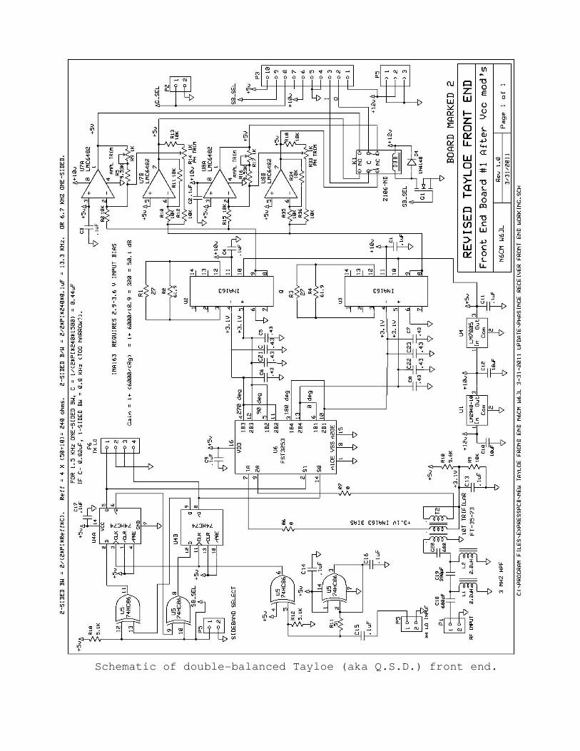
Schematic of double-balanced Tayloe (aka Q.S.D.) front end.
AD9850 DDS VFO/exciter for XMTR. The VFO output is keyed and shaped
and drives the 40 dB gain HB amp. Just 50mW of drive
VFO gives 550W out on the HF bands. I built this V
from an article by Curtis, WB2V, in July 1997 QEX. For several
years, Analog Devices provided free samples of DDS devices to any
homebrewer who requested them online. This resulted in many getting
their feet wet with DDS
build a VFO. It eliminates dial drives, variable capacitors,
inductors, band calibrations, and bandswitching. Plus, it has DC to
30 MHz coverage, (useful even as a clean sine wave audio source), and
no drift. Homebrew has
today.
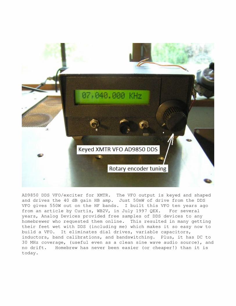
AD9850 DDS VFO/exciter for XMTR. The VFO output is keyed and shaped
and drives the 40 dB gain HB amp. Just 50mW of drive from the DDS
gives 550W out on the HF bands. I built this VFO ten years ago
from an article by Curtis, WB2V, in July 1997 QEX. For several
years, Analog Devices provided free samples of DDS devices to any
homebrewer who requested them online. This resulted in many getting
(including me) which makes it so easy now to
build a VFO. It eliminates dial drives, variable capacitors,
inductors, band calibrations, and bandswitching. Plus, it has DC to
30 MHz coverage, (useful even as a clean sine wave audio source), and
no drift. Homebrew has never been easier (or cheaper!) than it is
AD9850 DDS VFO/exciter for XMTR. The VFO output is keyed and shaped
from the DDS
FO ten years ago
from an article by Curtis, WB2V, in July 1997 QEX. For several
years, Analog Devices provided free samples of DDS devices to any
homebrewer who requested them online. This resulted in many getting
which makes it so easy now to
build a VFO. It eliminates dial drives, variable capacitors,
inductors, band calibrations, and bandswitching. Plus, it has DC to
30 MHz coverage, (useful even as a clean sine wave audio source), and
never been easier (or cheaper!) than it is
PIN diode QSK antenna T/R switch, mounted on rear of amplifier.
again, ugly-style on bare copper
1N4007 rectifier diodes used as PINs are visible at left center
Attenuation looking back into the input of the always
receiver is over 100dB when the key is down. Note ancient carbon
resistors from my junk box. Some of the inductors were salvaged from
junked computer power supplies. Cost to build: $0 out
best kind of project :o). This switch easily handles 600W and has
been in daily use for several years
hours. Oh, and brand new 1N4007 diodes are 10 cents each.
PIN diode QSK antenna T/R switch, mounted on rear of amplifier.
style on bare copper-clad serves just fine.
1N4007 rectifier diodes used as PINs are visible at left center
Attenuation looking back into the input of the always-connected
receiver is over 100dB when the key is down. Note ancient carbon
resistors from my junk box. Some of the inductors were salvaged from
junked computer power supplies. Cost to build: $0 out of pocket; the
best kind of project :o). This switch easily handles 600W and has
been in daily use for several years, with thousands of accumulated
Oh, and brand new 1N4007 diodes are 10 cents each.
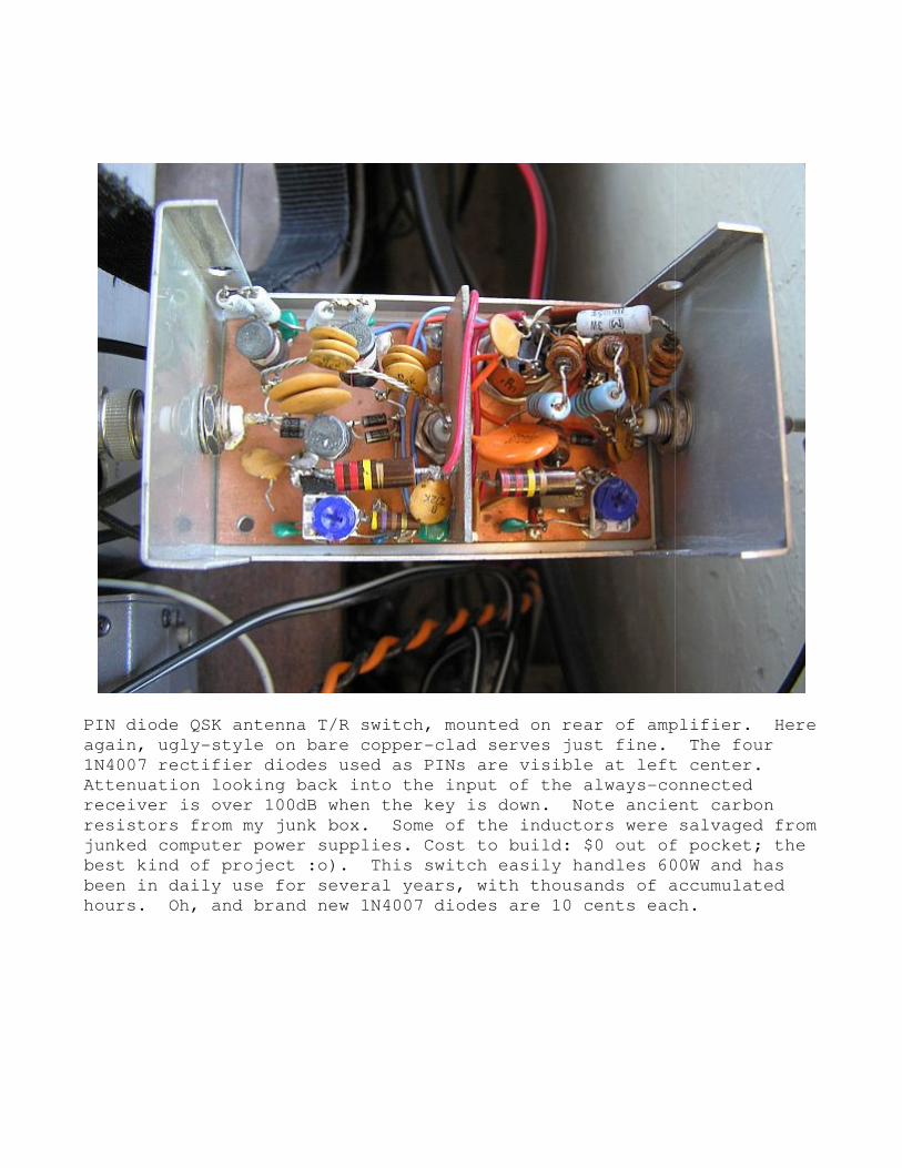
PIN diode QSK antenna T/R switch, mounted on rear of amplifier. Here
clad serves just fine. The four
1N4007 rectifier diodes used as PINs are visible at left center.
connected
receiver is over 100dB when the key is down. Note ancient carbon
resistors from my junk box. Some of the inductors were salvaged from
of pocket; the
best kind of project :o). This switch easily handles 600W and has
, with thousands of accumulated
Oh, and brand new 1N4007 diodes are 10 cents each.
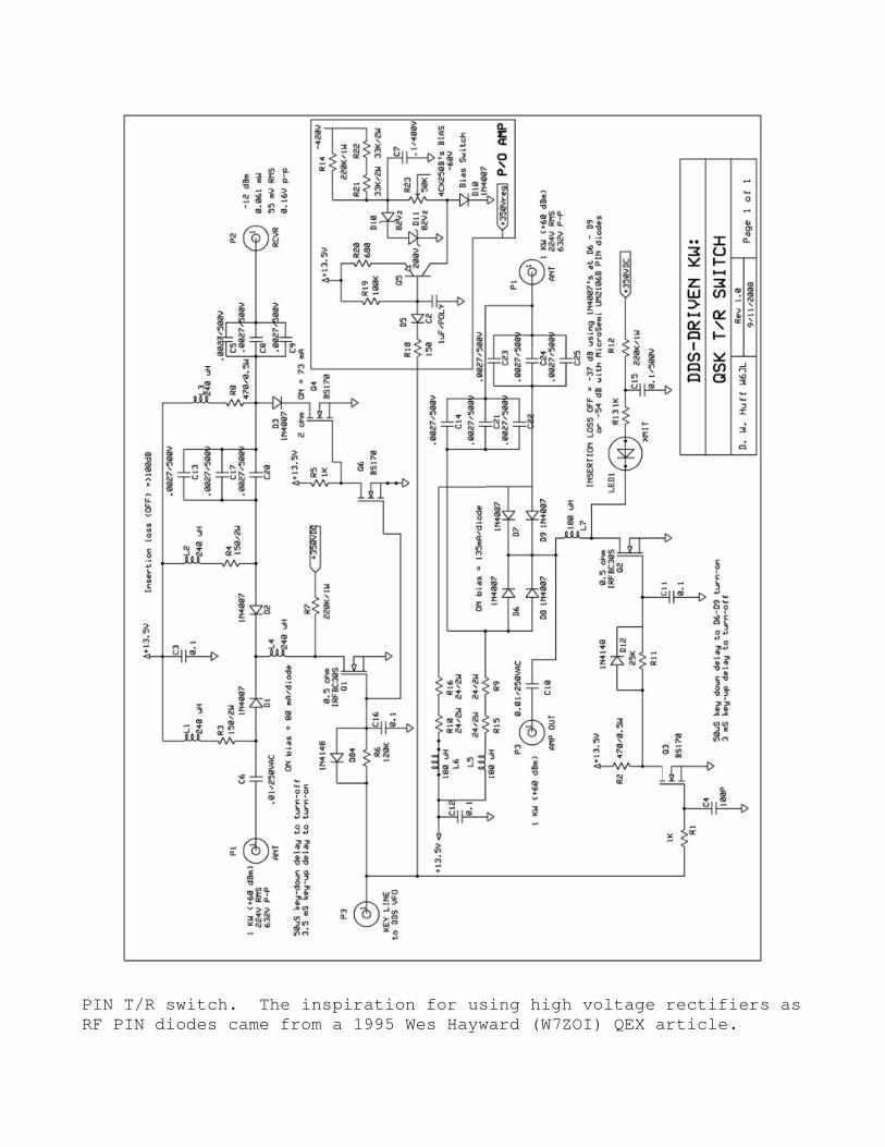
PIN T/R switch. The inspiration for using hig
RF PIN diodes came from a 1995 Wes Hayward (W7ZOI) QEX article.
PIN T/R switch. The inspiration for using high voltage rectifiers as
from a 1995 Wes Hayward (W7ZOI) QEX article.
h voltage rectifiers as
from a 1995 Wes Hayward (W7ZOI) QEX article.
UPDATE - 8/4/2011
Since my entire station consists of only HB equipment, including the
PC boards, with the exception of the PC board for the Tayloe (which
was made by ExpressPCB, at zero incremental cost, since Bob N6CM
tacked it onto another existing board order’s image), I decided I
wanted exclusively my own PC boards. To that end I built entirely
new Audio Processor and Filter and Audio boards, eliminating the for-
mer modified R2PRO entirely. But the Tayloe remained, so I laid out
yet another Tayloe and loaded it with only the parts required for a
LSB-only receiver. No need for selectable sidebands when one is a
CW-only op, right? This strips a bunch of parts out of the Tayloe
front end, including sideband selection relays, output summing amps,
USB amplitude and phase 15T pots, etc. Things keep getting simpler!
However I thought of this simplification after I had made the bare
board. So I just did not load the unnecessary major parts. See pix
below of board. A thing of beauty it ain’t; I made it single-sided
(solid copper on back side for GP) so there are plenty of jumper
wires. That notwithstanding, it works beautifully, and hears -142
dBm with 3 dB S+N/N ratio. Yet another illustration that cosmetics
is unrelated to performance (let’s hear it again for Ugly Construc-
tion :o)).
This is my third working Tayloe. What does a guy do with three hot
Tayloe front ends? Hmm, maybe I could make the LO multiple output
and then can simultaneously listen to three frequencies anywhere in
the HF range. The receiver is broadband, remember.
So, now the station is 100% homebrew (except for the components..
hmmm…).
Later,
Don

This is the one-sideband-only Tayloe mixer.
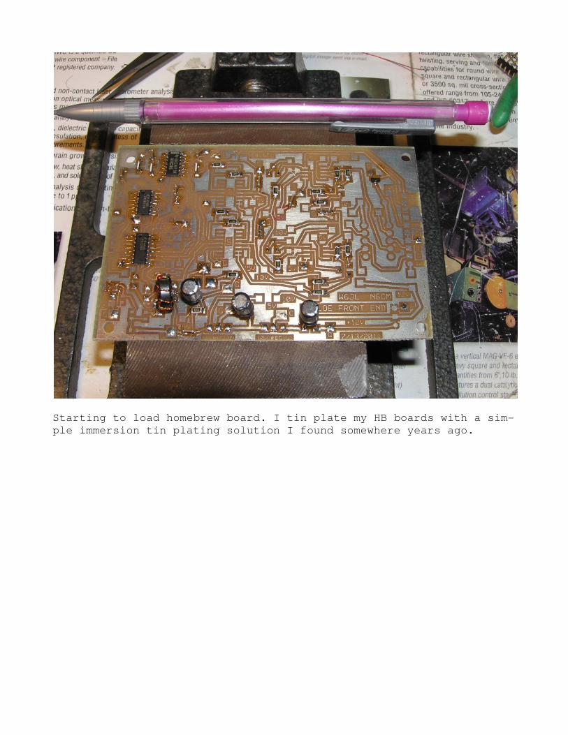
Starting to load homebrew board. I tin plate my HB boards with a sim-
ple immersion tin plating solution I found somewhere years ago.
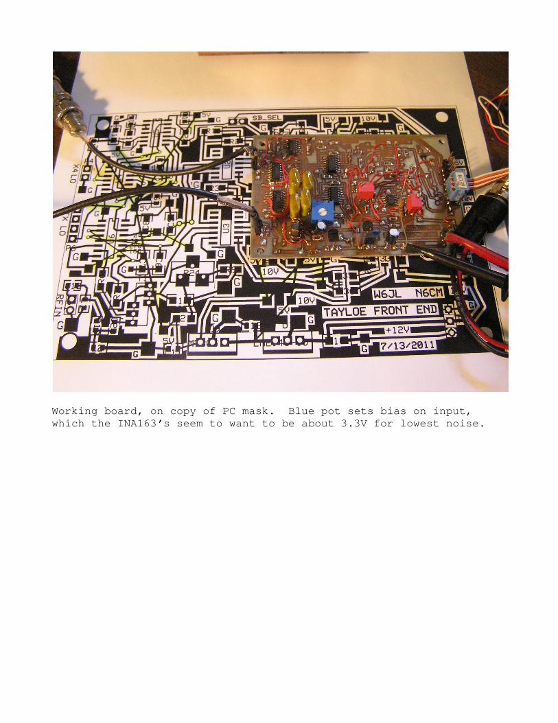
Working board, on copy of PC mask. Blue pot sets bias on input,
which the INA163’s seem to want to be about 3.3V for lowest noise.
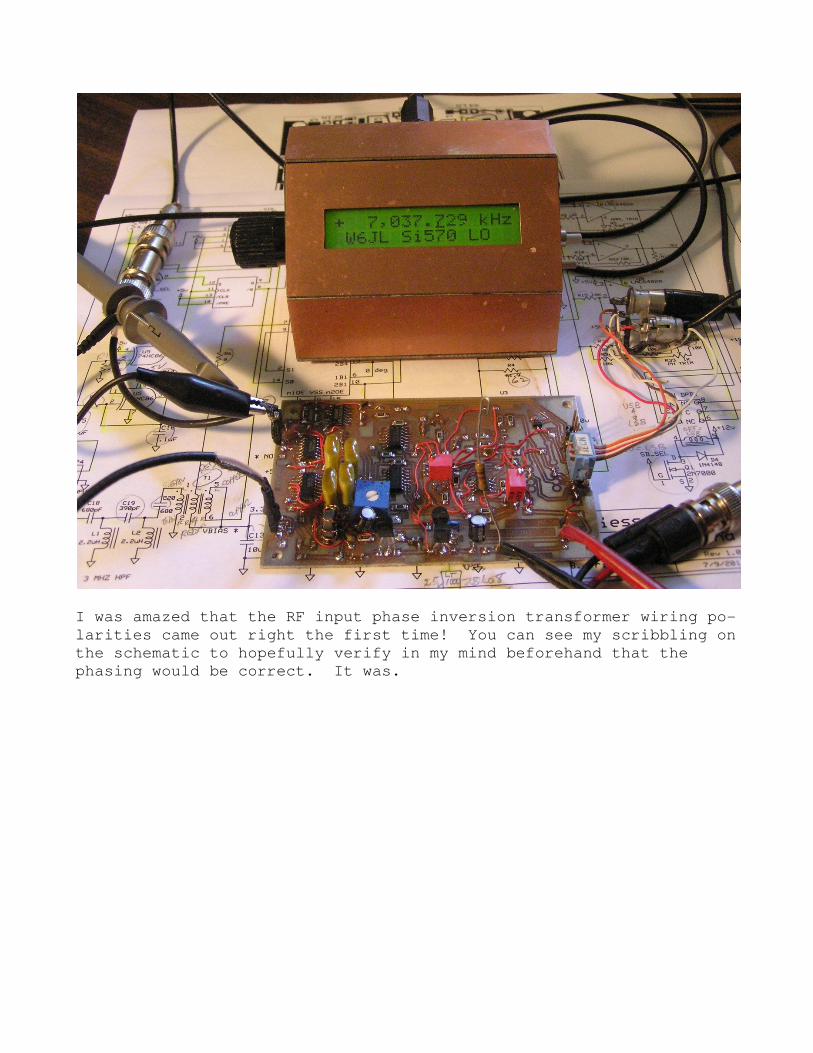
I was amazed that the RF input phase inversion transformer wiring po-
larities came out right the first time! You can see my scribbling on
the schematic to hopefully verify in my mind beforehand that the
phasing would be correct. It was.
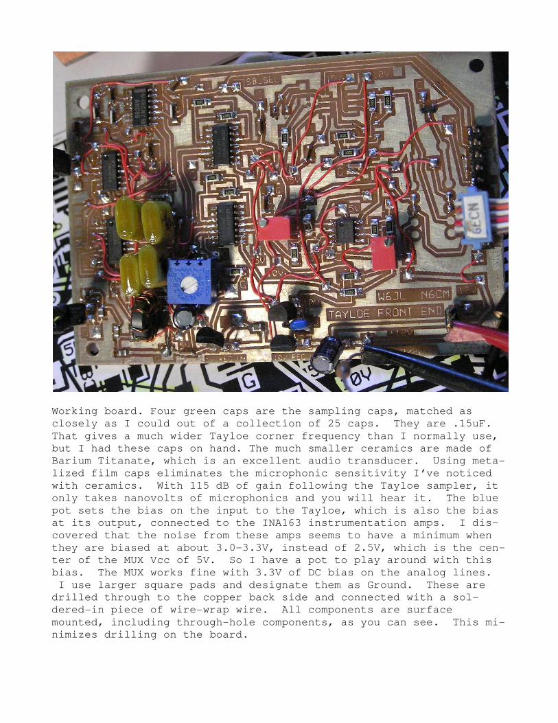
Working board. Four green caps are the sampling caps, matched as
closely as I could out of a collection of 25 caps. They are .15uF.
That gives a much wider Tayloe corner frequency than I normally use,
but I had these caps on hand. The much smaller ceramics are made of
Barium Titanate, which is an excellent audio transducer. Using meta-
lized film caps eliminates the microphonic sensitivity I’ve noticed
with ceramics. With 115 dB of gain following the Tayloe sampler, it
only takes nanovolts of microphonics and you will hear it. The blue
pot sets the bias on the input to the Tayloe, which is also the bias
at its output, connected to the INA163 instrumentation amps. I dis-
covered that the noise from these amps seems to have a minimum when
they are biased at about 3.0-3.3V, instead of 2.5V, which is the cen-
ter of the MUX Vcc of 5V. So I have a pot to play around with this
bias. The MUX works fine with 3.3V of DC bias on the analog lines.
I use larger square pads and designate them as Ground. These are
drilled through to the copper back side and connected with a sol-
dered-in piece of wire-wrap wire. All components are surface
mounted, including through-hole components, as you can see. This mi-
nimizes drilling on the board.
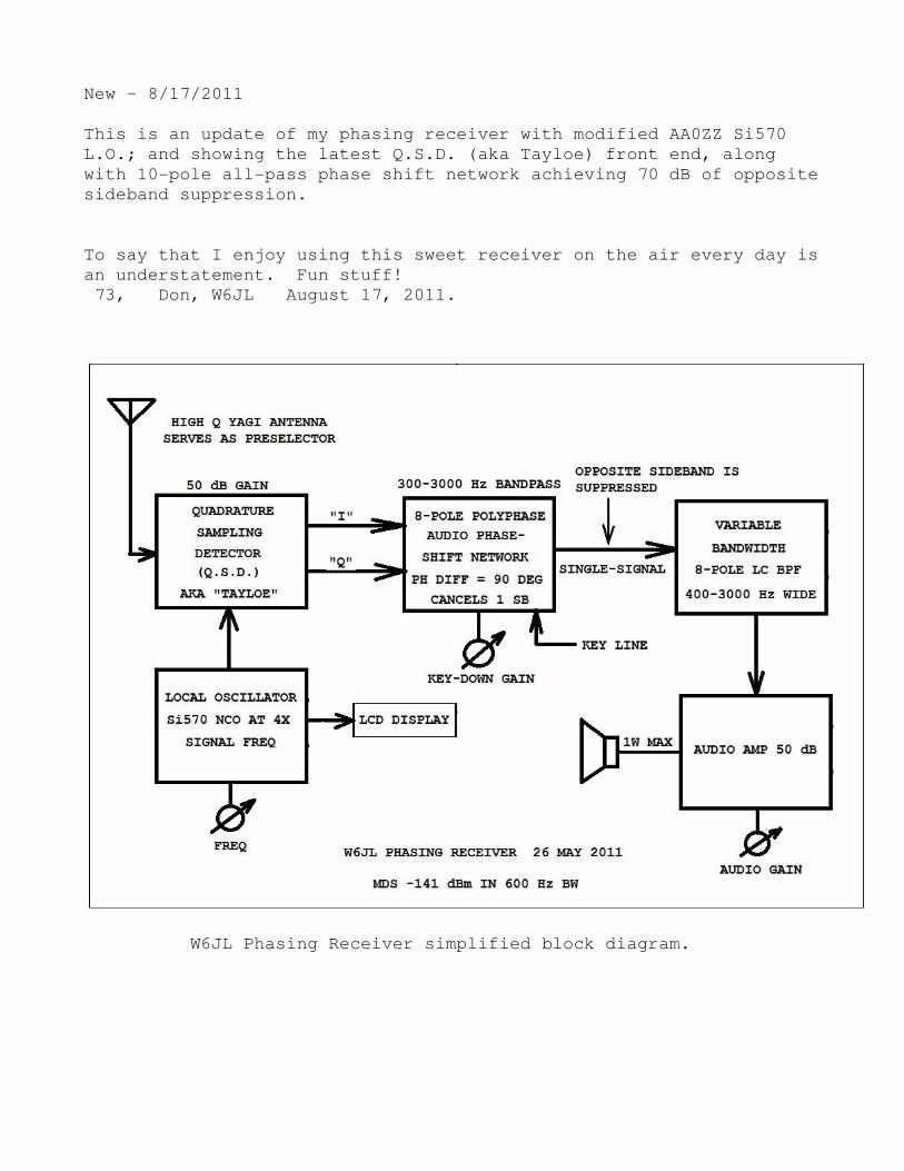
New – 8/17/2011
This is an update of my phasing receiver with modified AA0ZZ Si570
L.O.; and showing the latest Q.S.D. (aka Tayloe) front end, along
with 10-pole all-pass phase shift network achieving 70 dB of opposite
sideband suppression.
To say that I enjoy using this sweet receiver on the air every day is
an understatement. Fun stuff!
73, Don, W6JL August 17, 2011.
W6JL Phasing Receiver simplified block diagram.
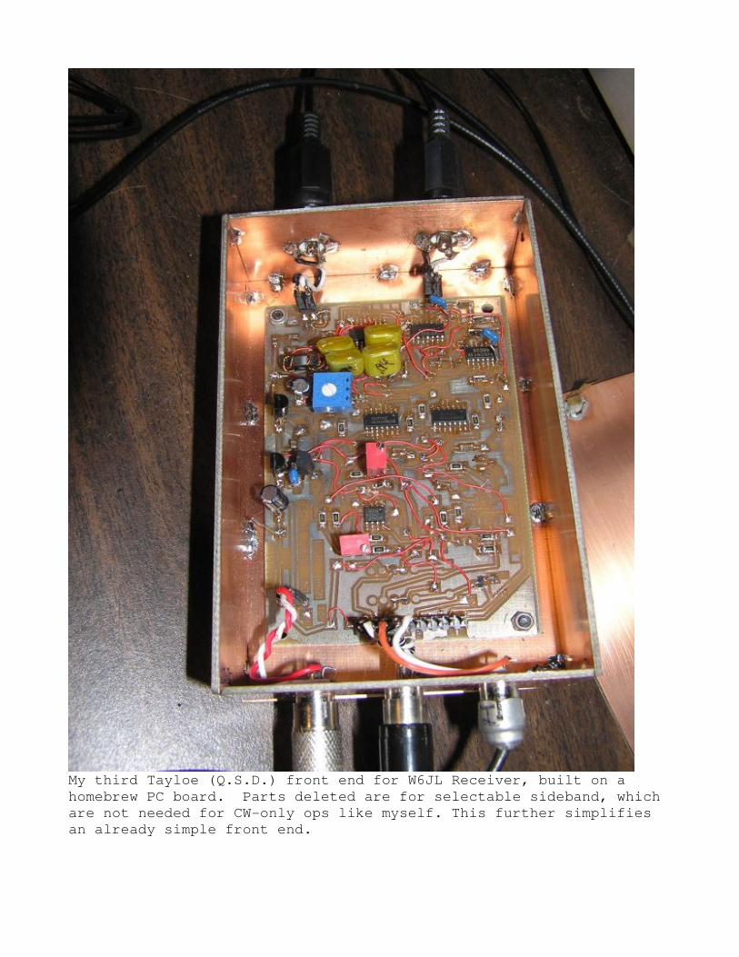
My third Tayloe (Q.S.D.) front end for W6JL Receiver, built on a
homebrew PC board. Parts deleted are for selectable sideband, which
are not needed for CW-only ops like myself. This further simplifies
an already simple front end.
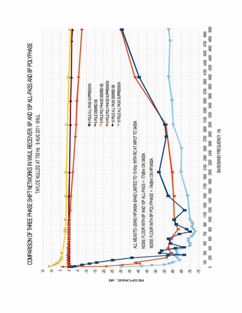
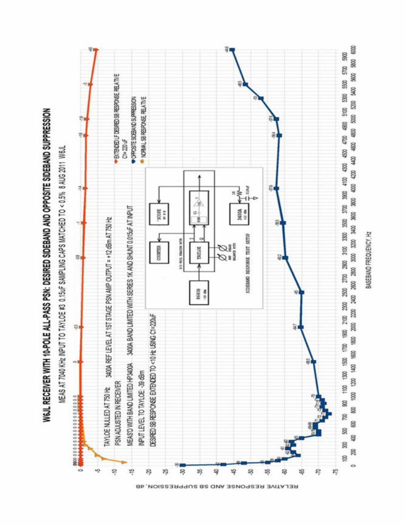
Above: Opposite and desired sideband response plots of phasing
networks tested in the W6JL Receiver. Adjustable 10-pole all-pass
network has excellent performance, especially over the CW passband of
the receiver where it has roughly 70 dB of opposite sideband
suppression.
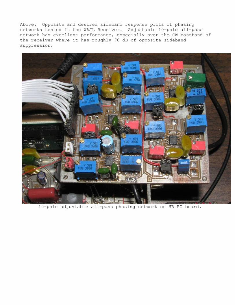
10-pole adjustable all-pass phasing network on HB PC board.

W6JL Receiver phasing section schematic, with baseband roofing filter
and QSK gain reduction.
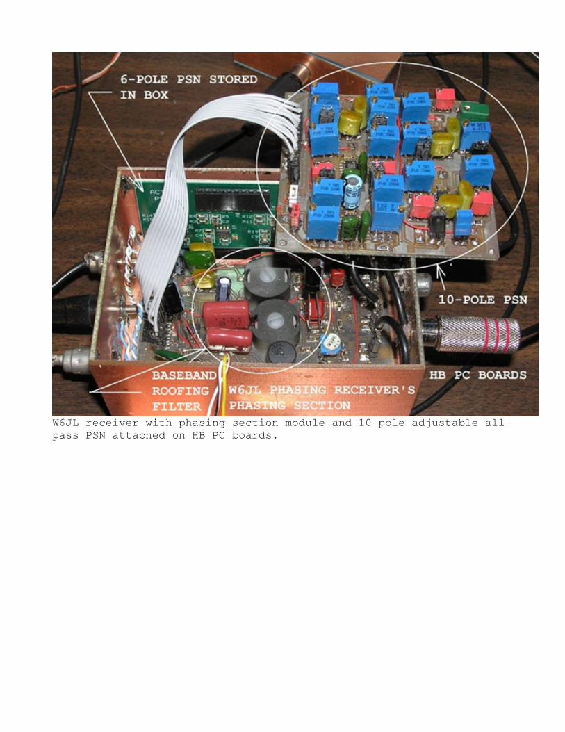
W6JL receiver with phasing section module and 10-pole adjustable all-
pass PSN attached on HB PC boards.
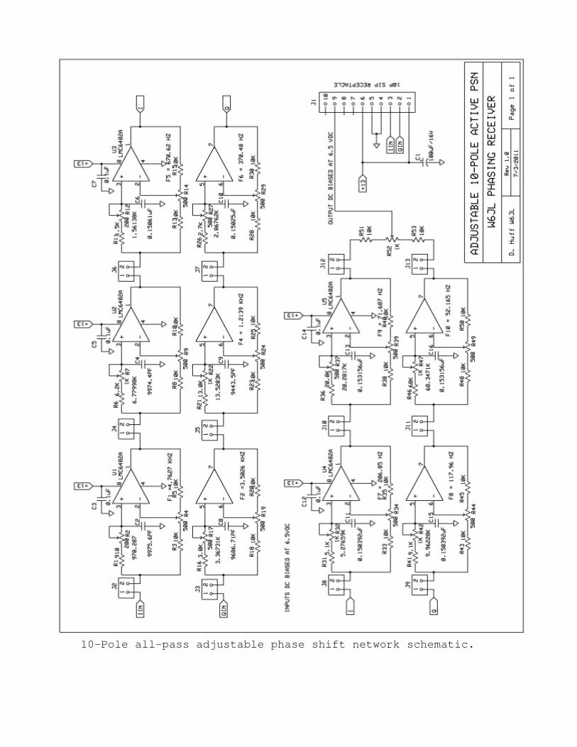
10-Pole all-pass adjustable phase shift network schematic.
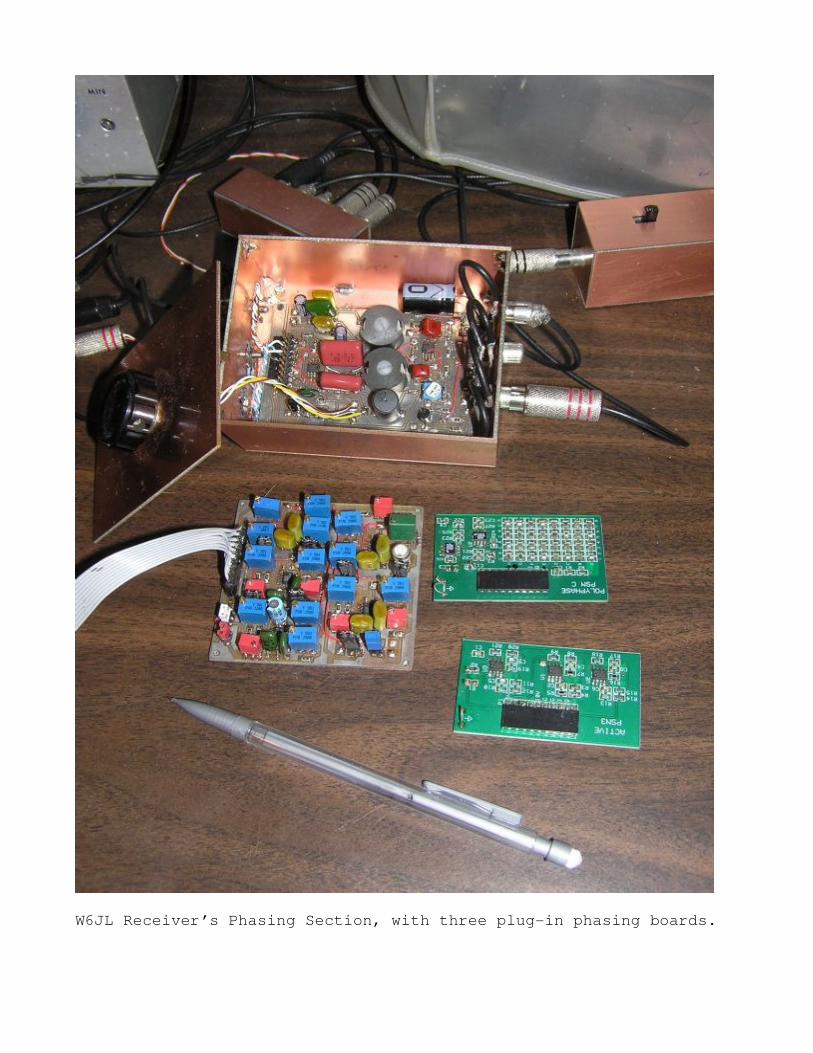
W6JL Receiver’s Phasing Section, with three plug-in phasing boards.
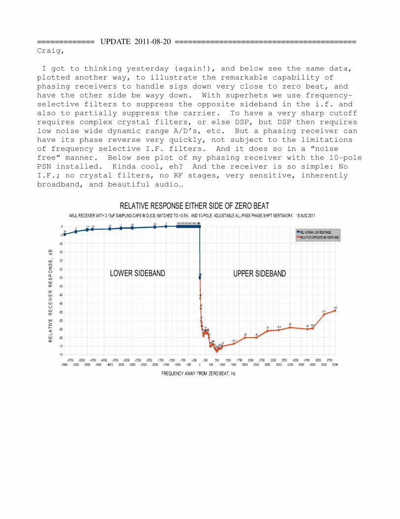
============= UPDATE 2011-08-20 =========================================
Craig,
I got to thinking yesterday (again!), and below see the same data,
plotted another way, to illustrate the remarkable capability of
phasing receivers to handle sigs down very close to zero beat, and
have the other side be wayy down. With superhets we use frequency-
selective filters to suppress the opposite sideband in the i.f. and
also to partially suppress the carrier. To have a very sharp cutoff
requires complex crystal filters, or else DSP, but DSP then requires
low noise wide dynamic range A/D’s, etc. But a phasing receiver can
have its phase reverse very quickly, not subject to the limitations
of frequency selective I.F. filters. And it does so in a “noise
free” manner. Below see plot of my phasing receiver with the 10-pole
PSN installed. Kinda cool, eh? And the receiver is so simple: No
I.F.; no crystal filters, no RF stages, very sensitive, inherently
broadband, and beautiful audio…
Recommended