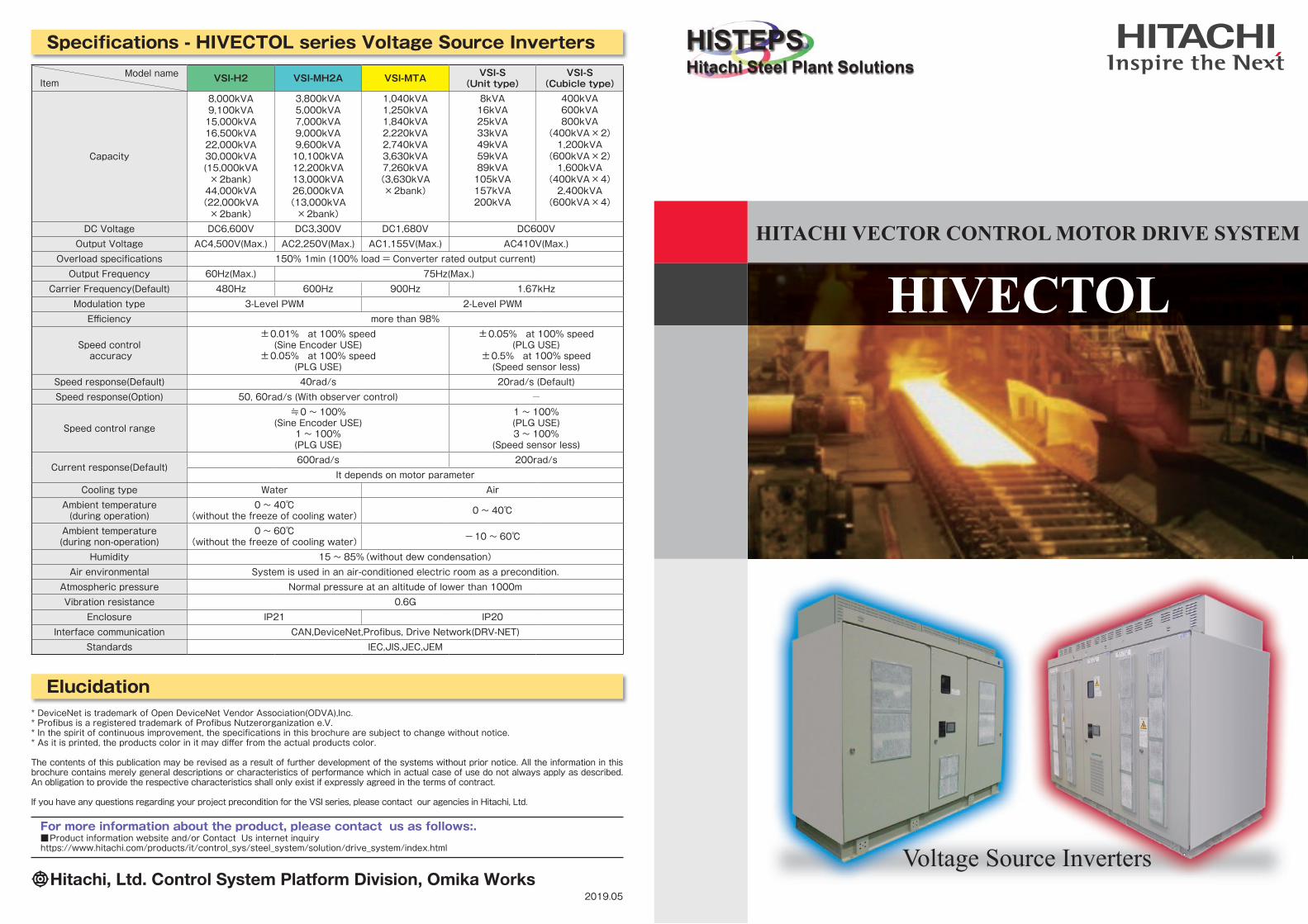
Specifi cations - HIVECTOL series Voltage Source Inverters
Elucidation* DeviceNet is trademark of Open DeviceNet Vendor Association(ODVA),Inc.* Profi bus is a registered trademark of Profi bus Nutzerorganization e.V.* In the spirit of continuous improvement, the specifi cations in this brochure are subject to change without notice.* As it is printed, the products color in it may diff er from the actual products color.
The contents of this publication may be revised as a result of further development of the systems without prior notice. All the information in this brochure contains merely general descriptions or characteristics of performance which in actual case of use do not always apply as described. An obligation to provide the respective characteristics shall only exist if expressly agreed in the terms of contract.
If you have any questions regarding your project precondition for the VSI series, please contact our agencies in Hitachi, Ltd.
For more information about the product, please contact us as follows:. ■Product information website and/or Contact Us internet inquiryhttps://www.hitachi.com/products/it/control_sys/steel_system/solution/drive_system/index.html
Hitachi, Ltd. Control System Platform Division, Omika Works2019.05
Model nameItem VSI-H2 VSI-MH2A VSI-MTA VSI-S
(Unit type)VSI-S
(Cubicle type)
Capacity
8,000kVA9,100kVA15,000kVA16,500kVA22,000kVA30,000kVA(15,000kVA×2bank)44,000kVA(22,000kVA×2bank)
3,800kVA5,000kVA7,000kVA9,000kVA9,600kVA10,100kVA12,200kVA13,000kVA26,000kVA(13,000kVA×2bank)
1,040kVA1,250kVA1,840kVA2,220kVA2,740kVA3,630kVA7,260kVA(3,630kVA×2bank)
8kVA16kVA25kVA33kVA49kVA59kVA89kVA105kVA157kVA200kVA
400kVA600kVA800kVA
(400kVA×2)1,200kVA
(600kVA×2)1,600kVA
(400kVA×4)2,400kVA
(600kVA×4)
DC Voltage DC6,600V DC3,300V DC1,680V DC600VOutput Voltage AC4,500V(Max.) AC2,250V(Max.) AC1,155V(Max.) AC410V(Max.)
Overload specifi cations 150% 1min (100% load = Converter rated output current) Output Frequency 60Hz(Max.) 75Hz(Max.)
Carrier Frequency(Default) 480Hz 600Hz 900Hz 1.67kHzModulation type 3-Level PWM 2-Level PWMEffi ciency more than 98%
Speed control accuracy
±0.01% at 100% speed(Sine Encoder USE)
±0.05% at 100% speed(PLG USE)
±0.05% at 100% speed(PLG USE)
±0.5% at 100% speed(Speed sensor less)
Speed response(Default) 40rad/s 20rad/s (Default)Speed response(Option) 50, 60rad/s (With observer control) -
Speed control range
≒0~ 100%(Sine Encoder USE)
1 ~ 100%(PLG USE)
1 ~ 100%(PLG USE)3 ~ 100%
(Speed sensor less)
Current response(Default)600rad/s 200rad/s
It depends on motor parameterCooling type Water Air
Ambient temperature(during operation)
0 ~ 40℃(without the freeze of cooling water) 0~ 40℃
Ambient temperature(during non-operation)
0 ~ 60℃(without the freeze of cooling water) -10~ 60℃
Humidity 15 ~ 85%(without dew condensation)Air environmental System is used in an air-conditioned electric room as a precondition.
Atmospheric pressure Normal pressure at an altitude of lower than 1000mVibration resistance 0.6G
Enclosure IP21 IP20Interface communication CAN,DeviceNet,Profi bus, Drive Network(DRV-NET)
Standards IEC,JIS,JEC,JEM
HISTEPSHitachi Steel Plant Solutions
HITACHI VECTOR CONTROL MOTOR DRIVE SYSTEM
HIVECTOL
Voltage Source Inverters
HITACHI VECTOR CONTROL MOTOR DRIVE SYSTEM HIVECTOL series
01 02
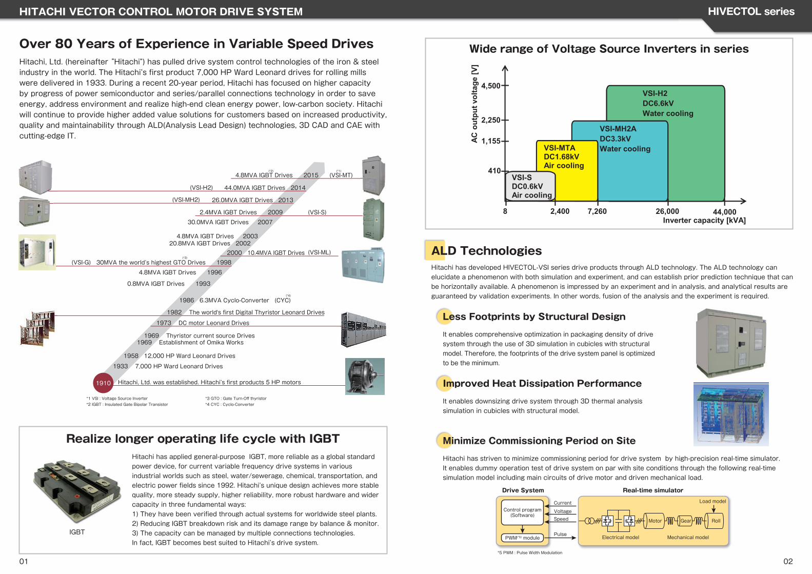
Over 80 Years of Experience in Variable Speed DrivesHitachi, Ltd. (hereinafter “Hitachi”) has pulled drive system control technologies of the iron & steel industry in the world. The Hitachi’s fi rst product 7,000 HP Ward Leonard drives for rolling mills were delivered in 1933. During a recent 20-year period, Hitachi has focused on higher capacity by progress of power semiconductor and series/parallel connections technology in order to save energy, address environment and realize high-end clean energy power, low-carbon society. Hitachi will continue to provide higher added value solutions for customers based on increased productivity, quality and maintainability through ALD(Analysis Lead Design) technologies, 3D CAD and CAE with cutting-edge IT.
Realize longer operating life cycle with IGBTHitachi has applied general-purpose IGBT, more reliable as a global standard power device, for current variable frequency drive systems in various industrial worlds such as steel, water/sewerage, chemical, transportation, and electric power fi elds since 1992. Hitachi’s unique design achieves more stable quality, more steady supply, higher reliability, more robust hardware and wider capacity in three fundamental ways:1) They have been verifi ed through actual systems for worldwide steel plants. 2) Reducing IGBT breakdown risk and its damage range by balance & monitor.3) The capacity can be managed by multiple connections technologies.In fact, IGBT becomes best suited to Hitachi’s drive system.
(VSI-MH2)
(VSI-H2)
1910
(VSI-G)
(VSI-ML)
(VSI-S)
(VSI-MT)(*1)(*2)
(*3)
(*4)
4.8MVA IGBT Drives 2015
44.0MVA IGBT Drives 2014
26.0MVA IGBT Drives 2013
30.0MVA IGBT Drives 2007
2.4MVA IGBT Drives 2009
20.8MVA IGBT Drives 20024.8MVA IGBT Drives 2003
2000 10.4MVA IGBT Drives
30MVA the world’s highest GTO Drives 1998
4.8MVA IGBT Drives 1996
0.8MVA IGBT Drives 1993
1986 6.3MVA Cyclo-Converter (CYC)
1982 The world's first Digital Thyristor Leonard Drives
1973 DC motor Leonard Drives
1969 Thyristor current source Drives1969 Establishment of Omika Works
1958 12,000 HP Ward Leonard Drives
1933 7,000 HP Ward Leonard Drives
Hitachi, Ltd. was established. Hitachi’s first products 5 HP motors
*1 VSI : Voltage Source Inverter*2 IGBT : Insulated Gate Bipolar Transistor
*3 GTO : Gate Turn-Off thyristor*4 CYC : Cyclo-Converter
IGBT
VSI-H2DC6.6kVWater cooling
VSI-MH2ADC3.3kVWater cooling
2,250
26,000
4,500
44,0002,400 7,260
1,155
410
VSI-MTADC1.68kVAir cooling
VSI-SDC0.6kVAir cooling
8
AC o
utpu
t vol
tage
[V]
Inverter capacity [kVA]
Motor Roll
Current
VoltageSpeed
Pulse
Real-time simulatorDrive System
Control program(Software)
PWM(*5) module Electrical model
Gear
Load model
Mechanical model
*5 PWM : Pulse Width Modulation
ALD TechnologiesHitachi has developed HIVECTOL-VSI series drive products through ALD technology. The ALD technology can elucidate a phenomenon with both simulation and experiment, and can establish prior prediction technique that can be horizontally available. A phenomenon is impressed by an experiment and in analysis, and analytical results are guaranteed by validation experiments. In other words, fusion of the analysis and the experiment is required.
Less Footprints by Structural Design
It enables comprehensive optimization in packaging density of drive system through the use of 3D simulation in cubicles with structural model. Therefore, the footprints of the drive system panel is optimized to be the minimum.
Improved Heat Dissipation Performance
It enables downsizing drive system through 3D thermal analysis simulation in cubicles with structural model.
Minimize Commissioning Period on Site
Hitachi has striven to minimize commissioning period for drive system by high-precision real-time simulator. It enables dummy operation test of drive system on par with site conditions through the following real-time simulation model including main circuits of drive motor and driven mechanical load.
Wide range of Voltage Source Inverters in series
HITACHI VECTOR CONTROL MOTOR DRIVE SYSTEM HIVECTOL series
03 04
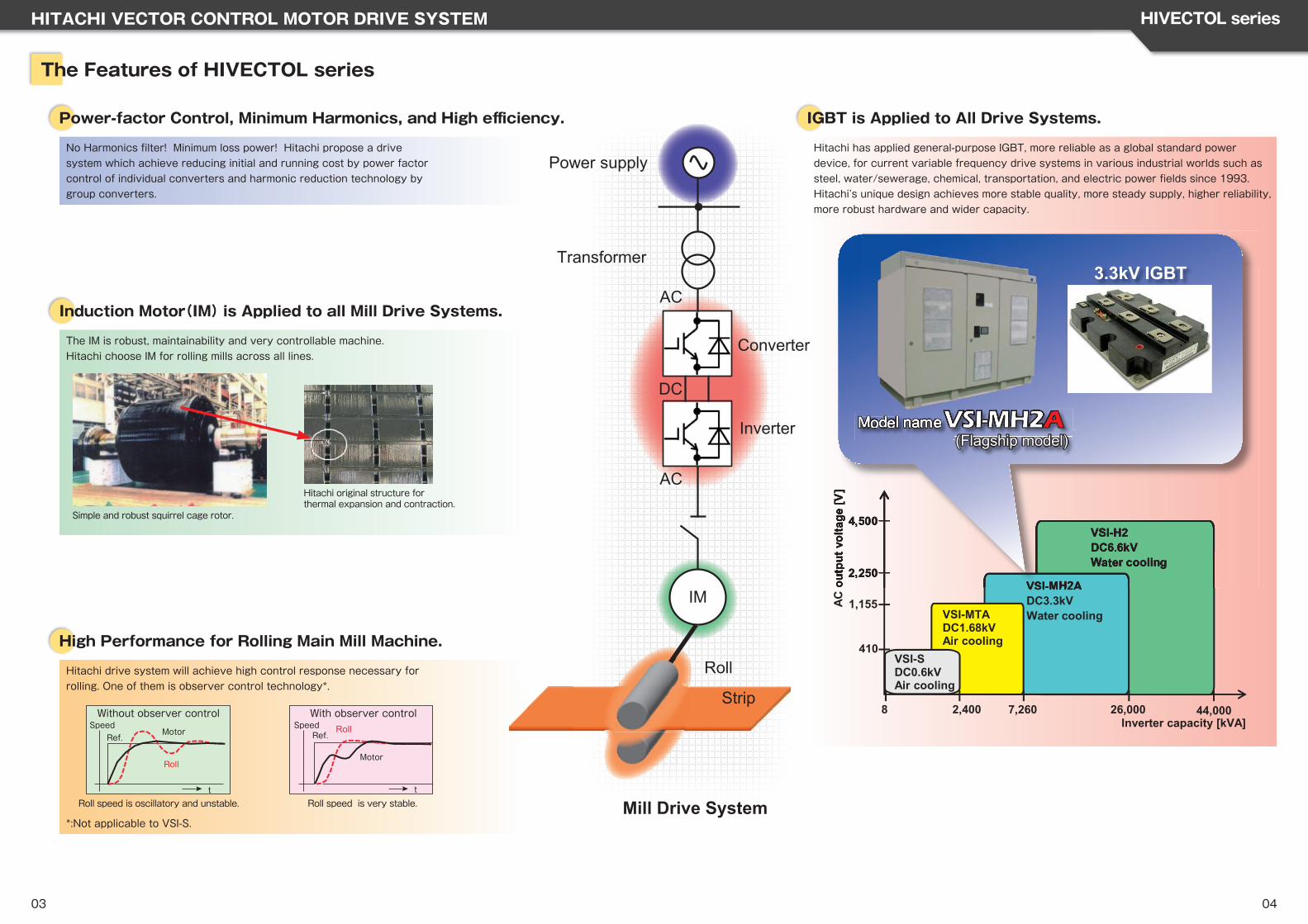
The Features of HIVECTOL series
Power-factor Control, Minimum Harmonics, and High effi ciency.
No Harmonics fi lter! Minimum loss power! Hitachi propose a drive system which achieve reducing initial and running cost by power factor control of individual converters and harmonic reduction technology by group converters.
Induction Motor(IM) is Applied to all Mill Drive Systems.
The IM is robust, maintainability and very controllable machine.Hitachi choose IM for rolling mills across all lines.
Simple and robust squirrel cage rotor.
Hitachi original structure for thermal expansion and contraction.
High Performance for Rolling Main Mill Machine.
Hitachi drive system will achieve high control response necessary for rolling. One of them is observer control technology*.
Motor
Roll
Ref.
t
Roll
Motor
Ref.
t
Without observer control With observer controlSpeed Speed
Roll speed is oscillatory and unstable. Roll speed is very stable.
*:Not applicable to VSI-S.
IGBT is Applied to All Drive Systems.
Hitachi has applied general-purpose IGBT, more reliable as a global standard power device, for current variable frequency drive systems in various industrial worlds such as steel, water/sewerage, chemical, transportation, and electric power fi elds since 1993.Hitachi’s unique design achieves more stable quality, more steady supply, higher reliability, more robust hardware and wider capacity.
VSI-H2DC6.6kVWater cooling
VSI-MH2ADC3.3kVWater cooling
2,250
26,000
4,500
44,0002,400 7,260
1,155
410
VSI-MTADC1.68kVAir cooling
VSI-SDC0.6kVAir cooling
8
ACou
tput
volta
ge [V
]
Inverter capacity [kVA]
VSI-H2DC6.6kVWater cooling
VSI-MH2A2,250
4,500
outp
utvo
ltage
[V]
3.3kV IGBT
Model nameModeModeModeModeModel nananammee(Flagship model)
Power supply
Converter
Transformer
Roll
Strip
Inverter
AC
AC
DC
IM
Mill Drive System
HITACHI VECTOR CONTROL MOTOR DRIVE SYSTEM HIVECTOL series
05 06
Hitachi will strive to live up to customer trust through our cell concept production by means of standardization (classifi cation of designing data based on cell concept) with product specifi cations.Cells are combined according to product composition instructions in order to achieve manufacturing in which cost reduction and stable quality go together.
Standardization of materials(Drawing, parts, circuit) → Stabilized function cell
Links to allDesign Manufacture Test SupplyManufacturingProcess
ProductionControl
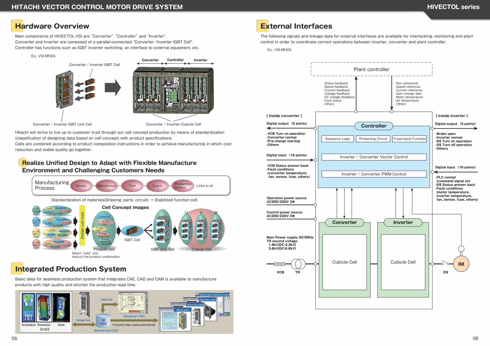
Hardware OverviewMain components of HIVECTOL-VSI are “Converter”, “Controller” and “Inverter”.Converter and Inverter are composed of a parallel-connected “Converter /Inverter IGBT Cell”.Controller has functions such as IGBT inverter switching, an interface to external equipment, etc.
Realize Unifi ed Design to Adapt with Flexible ManufactureEnvironment and Challenging Customers Needs
Integrated Production SystemBasic data for seamless production system that integrates CAE, CAD and CAM is available to manufacture products with high quality and shorten the production lead time.
External InterfacesThe following signals and linkage data for external interfaces are available for interlocking, monitoring and plant control in order to coordinate correct operations between inverter, converter and plant controller.
IM
[ Inside converter ]
Plant controller
VCB TR
[ Inside inverter ]
DS
Controller
Protecting Circuit Trace back Function
Inverter / Converter Vector Control
Inverter / Converter PWM Control
Inverter
Cubicle Cell
Converter
Cubicle Cell
-Status feedback-Speed feedback-Current feedback-Voltage feedback-DC voltage feedback-Fault status-Others
-Run commands-Speed reference-Current reference-Gain change data-Motor temperature-Air temperature-Others
Sequence Logic
Digital output (5 points)
-VCB Turn on operation-Converter normal-Pre-charge starting-Others
Digital input (16 points)
-VCB Status answer back-Fault conditions (converter temperature, fan, sensor, fuse, others)
Operation power sourceAC200/220V 3Φ
Control power sourceAC200/220V 3Φ
Main Power supply 50/60HzTR second voltage 1.9kV(DC:3.3kV) 3.6kV(DC:6.6kV)
Digital output (5 points)
-Brake open-Inverter normal-DS Turn on operation-DS Turn off operation-Others
Digital input (16 points)
-PLC normal (command signal on)-DS Status answer back-Fault conditions (motor temperature, inverter temperature, fan, sensor, fuse, others)
Converter Controller InverterConverter / Inverter IGBT Cell
Converter / Inverter IGBT Unit Cell Converter / Inverter Cubicle Cell
Ex.: VSI-MH2A
Product Cell
IGBT Cell
‶Cell"Concept
CubicleCell
A UnitCell
B UnitCell
Cell Concept images
Design cell type
IGBT Unit Cell Cubicle Cell
VU W
Select “cells” and instruct the product combination
Parts SequenceDrawingCubicle Assembly
Parts SequenceDrawing
AssemblyFrame
Parts Sequence
AssemblyFrame
SequenceParts
Assembly Drawing
Frame Cell
B UnitCell
A UnitCellOverallSequenceOverallAssemblyinstruction
Ex.: VSI-MH2A
HITACHI VECTOR CONTROL MOTOR DRIVE SYSTEM HIVECTOL series
07 08
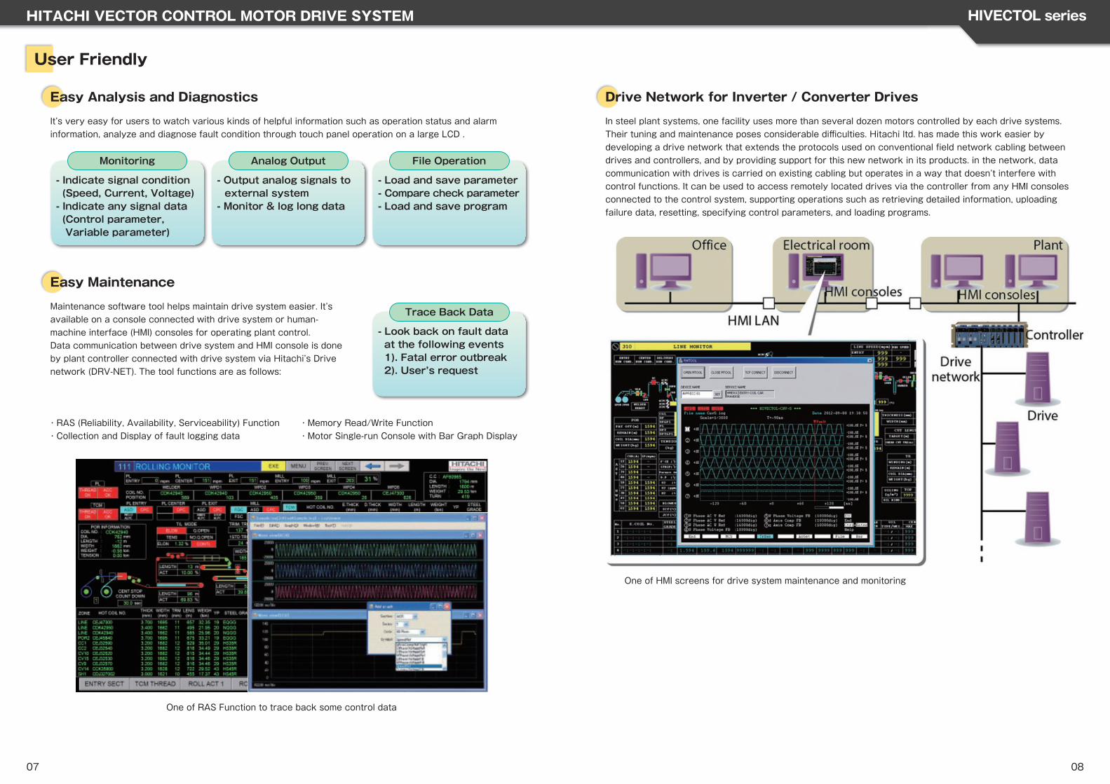
・RAS (Reliability, Availability, Serviceability) Function・Collection and Display of fault logging data
・Memory Read/Write Function・Motor Single-run Console with Bar Graph Display
- Output analog signals to external system- Monitor & log long data
Analog Output
- Indicate signal condition (Speed, Current, Voltage)- Indicate any signal data (Control parameter, Variable parameter)
Monitoring
- Load and save parameter- Compare check parameter- Load and save program
File Operation
- Look back on fault data at the following events 1). Fatal error outbreak 2). User’s request
Trace Back Data
One of RAS Function to trace back some control data
User Friendly
Easy Analysis and Diagnostics
It’s very easy for users to watch various kinds of helpful information such as operation status and alarm information, analyze and diagnose fault condition through touch panel operation on a large LCD .
Easy Maintenance
Maintenance software tool helps maintain drive system easier. It’s available on a console connected with drive system or human-machine interface (HMI) consoles for operating plant control. Data communication between drive system and HMI console is done by plant controller connected with drive system via Hitachi’s Drive network (DRV-NET). The tool functions are as follows:
Drive Network for Inverter / Converter Drives
In steel plant systems, one facility uses more than several dozen motors controlled by each drive systems. Their tuning and maintenance poses considerable diffi culties. Hitachi ltd. has made this work easier by developing a drive network that extends the protocols used on conventional fi eld network cabling between drives and controllers, and by providing support for this new network in its products. in the network, data communication with drives is carried on existing cabling but operates in a way that doesn’t interfere with control functions. It can be used to access remotely located drives via the controller from any HMI consoles connected to the control system, supporting operations such as retrieving detailed information, uploading failure data, resetting, specifying control parameters, and loading programs.
One of HMI screens for drive system maintenance and monitoring
HITACHI VECTOR CONTROL MOTOR DRIVE SYSTEM HIVECTOL series
10
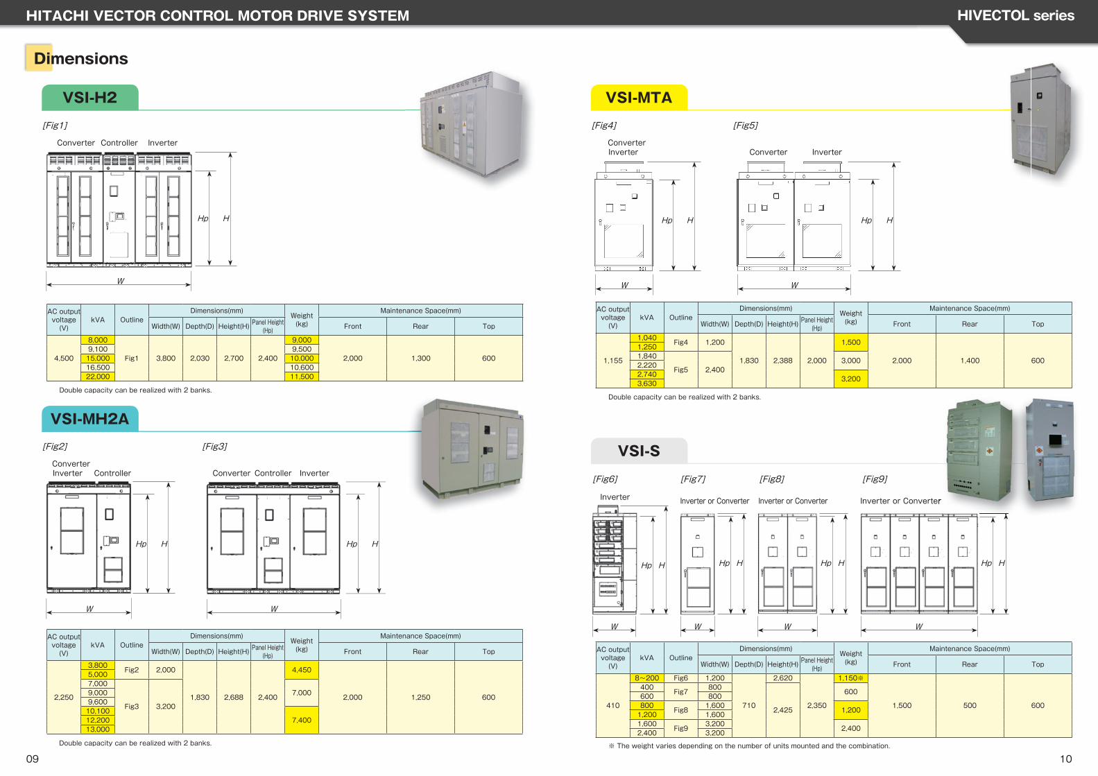
Dimensions
VSI-H2
VSI-MH2A
[Fig1]
[Fig3]
Converter
Converter
Controller
Controller
Inverter
Inverter
Hp H
W
Hp H
W
VSI-MTA
VSI-S
[Fig6] [Fig7] [Fig8] [Fig9]
Inverter or Converter Inverter or Converter Inverter or ConverterInverter
Hp H
W
Hp H
W
Hp H
W
Hp H
W
AC output voltage(V)
kVA OutlineDimensions(mm)
Weight(kg)
Maintenance Space(mm)
Width(W) Depth(D) Height(H) Panel Height(Hp) Front Rear Top
4,500
8,000
Fig1 3,800 2,030 2,700 2,400
9,000
2,000 1,300 6009,100 9,50015,000 10,00016,500 10,60022,000 11,500
Double capacity can be realized with 2 banks.
ConverterControllerInverter
Hp H
W
[Fig2]
AC output voltage(V)
kVA OutlineDimensions(mm)
Weight(kg)
Maintenance Space(mm)
Width(W) Depth(D) Height(H) Panel Height(Hp) Front Rear Top
2,250
3,800Fig2 2,000
1,830 2,688 2,400
4,450
2,000 1,250 600
5,0007,000
Fig3 3,200
7,0009,0009,60010,100
7,40012,20013,000
Double capacity can be realized with 2 banks.
[Fig5]
Converter Inverter
Hp H
W
ConverterInverter
Hp H
W
[Fig4]
AC output voltage(V)
kVA OutlineDimensions(mm)
Weight(kg)
Maintenance Space(mm)
Width(W) Depth(D) Height(H) Panel Height(Hp) Front Rear Top
1,155
1,040Fig4 1,200
1,830 2,388 2,000
1,500
2,000 1,400 600
1,2501,840
Fig5 2,4003,000
2,2202,740
3,2003,630
Double capacity can be realized with 2 banks.
AC output voltage(V)
kVA OutlineDimensions(mm)
Weight(kg)
Maintenance Space(mm)
Width(W) Depth(D) Height(H) Panel Height(Hp) Front Rear Top
410
8~200 Fig6 1,200
710
2,620
2,350
1,150※
1,500 500 600
400Fig7
800
2,425
600600 800800
Fig81,600
1,2001,200 1,6001,600
Fig93,200
2,4002,400 3,200
09※ The weight varies depending on the number of units mounted and the combination.
Inverter or Converter
Recommended


![Quarterly Report - Hitachi · 2020-02-28 · Hitachi Kokusai Electric Inc. [Consolidated subsidiaries] Hitachi Industry & Control Solutions, Ltd. Hitachi Plant Services Co., Ltd](https://img.pdfslide.us/doc/110x75/5f2f7176f85d3c1d652bbf74/quarterly-report-2020-02-28-hitachi-kokusai-electric-inc-consolidated-subsidiaries.jpg)