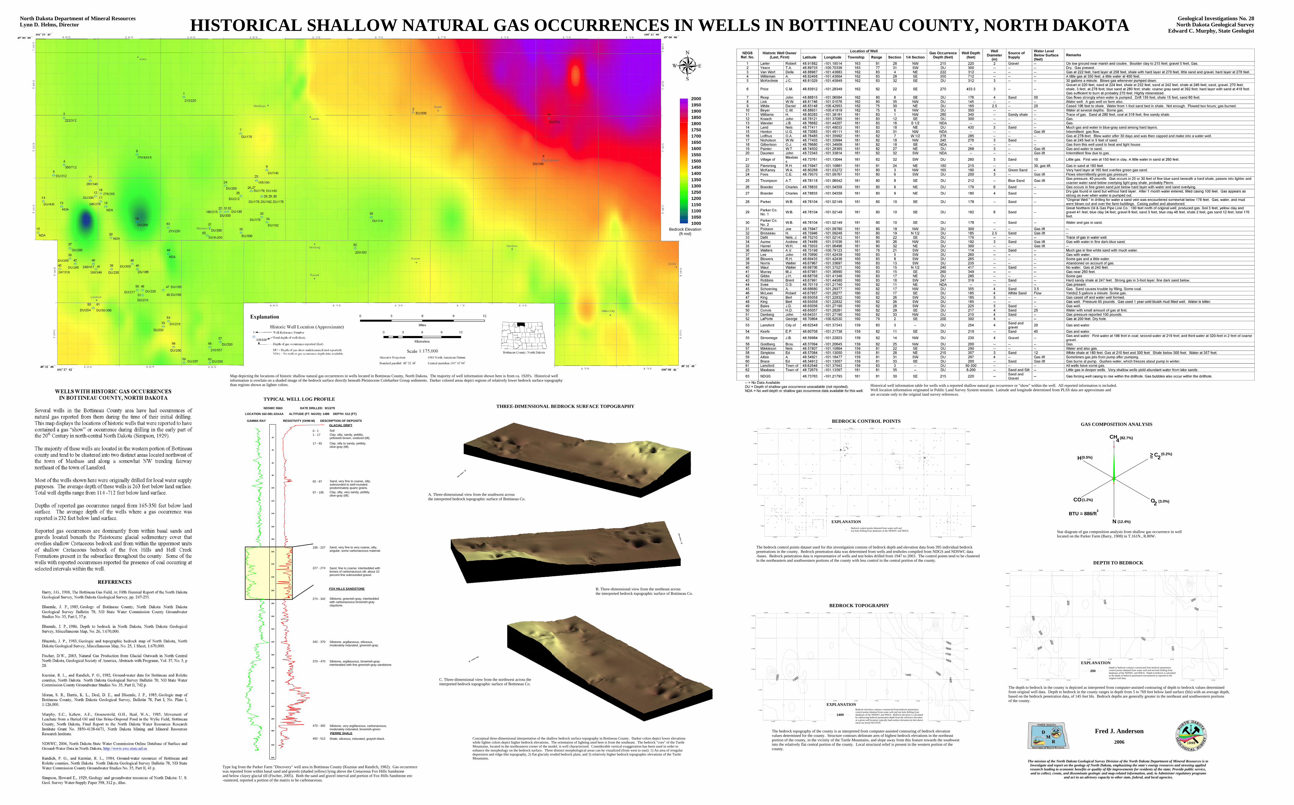
HISTORICAL SHALLOW NATURAL GAS OCCURRENCES IN WELLS IN BOTTINEAU COUNTY, NORTH DAKOTA Geological Investigations No. 28North Dakota Geological Survey
Edward C. Murphy, State Geologist
North Dakota Department of Mineral ResourcesLynn D. Helms, Director
Conceptual three-dimensional interpretation of the shallow bedrock surface topography in Bottineau County. Darker colors depict lower elevationswhile lighter colors depict higher bedrock elevations. The orientation of lighting used here is from the southeast. The bedrock "core" of the TurtleMountains, located in the northeastern corner of the model, is well characterized. Considerable vertical exaggeration has been used in order toenhance the morphology on the bedrock surface. Three distinct morphological areas can be visualized (from west to east): 1) An area of irregulardepression and ridge-like topography, 2) flat glacialy eroded bedrock plain, and 3) relatively higher bedrock topographic elevations of the TurtleMountains.
Map depicting the locations of historic shallow natural gas occurrences in wells located in Bottineau County, North Dakota. The majority of well information shown here is from ca. 1920's. Historical wellinformation is overlain on a shaded image of the bedrock surface directly beneath Pleistocene Coleharbor Group sediments. Darker colored areas depict regions of relatively lower bedrock surface topography than regions shown as lighter colors.
A. Three-dimensional view from the southwest across the interpreted bedrock topographic surface of Bottineau Co.
B. Three-dimensional view from the northeast across the interpreted bedrock topographic surface of Bottineau Co.
C. Three-dimensional view from the northwest across the interpreted bedrock topographic surface of Bottineau Co.
R. 74 W.R. 75 W.
R. 76 W.R. 77 W.R. 78 W.R. 79 W.R. 80 W.
R. 81 W.R. 82 W.R. 83 W.
T. 164 N.
T. 163 N.
T. 162 N.
T. 161 N.
T. 160 N.
T. 159 N.
R. 74 W.R. 75 W.R. 76 W.R. 77 W.R. 78 W.R. 79 W.R. 80 W.R. 81 W.R. 82 W.R. 83 W.
T. 164 N.
T. 163 N.
T. 162 N.
T. 161 N.
T. 160 N.
T. 159 N.
BEDROCK CONTROL POINTS
Bedrock control points obtained from water well and test hole drilling from databases of the NDSWC and NDGS.
EXPLANATION
Type log from the Parker Farm "Discovery" well area in Bottineau County (Kuzniar and Randich, 1982). Gas occurrence was reported from within basal sand and gravels (shaded yellow) lying above the Cretaceous Fox Hills Sandstone and below clayey glacial till (Fischer, 2005). Both the sand and gravel interval and portion of Fox Hills Sandstone enc-ountered, reported a portion of the matrix to be carbonaceous.
The bedrock control points dataset used for this investigation consists of bedrock depth and elevation data from 395 individual bedrock penetrations in the county. Bedrock penetration data was determined from wells and testholes compiled from NDGS and NDSWC data-bases. Bedrock penetration data is representative of wells and test holes drilled from 1947 to 2003. The control points tend to be clusteredin the northeastern and southwestern portions of the county with less control in the central portion of the county.
Historical well information table for wells with a reported shallow natural gas occurrence or "show" within the well. All reported information is included.Well location information originated in Public Land Survey System notation. Latitude and longitude determined from PLSS data are approximate andare accurate only to the original land survey references.
THREE-DIMENSIONAL BEDROCK SURFACE TOPOGRAPHY TYPICAL WELL LOG PROFILE
DEPTH TO BEDROCK
R. 74 W.R. 75 W.
R. 76 W.R. 77 W.R. 78 W.R. 79 W.R. 80 W.
R. 81 W.R. 82 W.R. 83 W.
T. 164 N.
T. 163 N.
T. 162 N.
T. 161 N.
T. 160 N.
T. 159 N.
R. 74 W.R. 75 W.R. 76 W.R. 77 W.R. 78 W.R. 79 W.R. 80 W.R. 81 W.R. 82 W.R. 83 W.
T. 164 N.
T. 163 N.
T. 162 N.
T. 161 N.
T. 160 N.
T. 159 N.
EXPLANATIONDepth to bedrock contours constructed from bedrock penetration control points obtained from water well and test hole drilling from databases of the NDSWC and NDGS. Depth to bedrock is calculated as the depth of bedrock penetration encountered as reported in the original well data.
200
BEDROCK TOPOGRAPHY
R. 74 W.R. 75 W.
R. 76 W.R. 77 W.R. 78 W.R. 79 W.R. 80 W.
R. 81 W.R. 82 W.R. 83 W.
T. 164 N.
T. 163 N.
T. 162 N.
T. 161 N.
T. 160 N.
T. 159 N.
R. 74 W.R. 75 W.R. 76 W.R. 77 W.R. 78 W.R. 79 W.R. 80 W.R. 81 W.R. 82 W.R. 83 W.
T. 164 N.
T. 163 N.
T. 162 N.
T. 161 N.
T. 160 N.
T. 159 N.
The bedrock topography of the county is as interpreted from computer-assisted contouring of bedrock elevation values determined for the county. Structure contours delineate ares of highest bedrock elevations in the northeastportion of the county, in the vicinity of the Turtle Mountains, and slope away from this feature towards the southwestinto the relatively flat central portion of the county. Local structural relief is present in the western portion of the county.
EXPLANATIONBedrock elevation contours constructed from bedrock penetration control points obtained from water well and test hole drilling from databases of the NDSWC and NDGS. Bedrock elevation is calculated by subtracting bedrock penetration depth from the reference elevationat a given well location; typically land surface elevation (in feet abovemean sea level) NGVD29.
1400
Star diagram of gas composition analysis from shallow gas occurrence in welllocated on the Parker Farm (Barry, 1908) in T.161N., R.80W.
N
H
CH4
=> C2
O2CO
(82.7%)
(0.2%)
(3.0%)
(12.4%)
(1.2%)
(0.5%)
BTU = 886/ft3
GAS COMPOSITION ANALYSIS
The mission of the North Dakota Geological Survey Division of the North Dakota Department of Mineral Resources is to Investigate and report on the geology of North Dakota, emphasizing the state's energy resources and stressing applied research leading to economic benefits or quality of life improvements for residents of the state; Provide public service, and to collect, create, and disseminate geologic and map-related information, and; to Administer regulatory programs
and act in an advisory capacity to other state, federal, and local agencies.
Fred J. Anderson2006
The depth to bedrock in the county is depicted as interpreted from computer-assisted contouring of depth to bedrock values determined from original well data. Depth to bedrock in the county ranges in depth from 5 to 769 feet below land surface (bls) with an average depth, based on the bedrock penetration data, of 145 feet bls. Bedrock depths are generally greater in the northeast and southwestern portionsof the county.
520
LOCATION 162-081-22AAA
NDSWC 5563 DATE DRILLED: 9/13/79
DEPTH: 512 (FT)ALTITUDE (FT. NGVD): 1489
GAMMA RAY RESISTIVITY (OHM-M) DESCRIPTION OF DEPOSITSGLACIAL DRIFT
FOX HILLS SANDSTONE
0 - 11 - 17
17 - 92
92 - 97
97 - 195
195 - 227
227 - 274
274 - 342
342 - 370
370 - 470
470 - 492
492 - 512
PIERRE SHALE
SoilClay, silty, sandy, pebbly, yellowish-brown, oxidized (till).
Clay, silty to sandy, pebbly, olive-gray (till).
Sand, very fine to coarse, silty, subrounded to well-rounded; predominately quartz grains.Clay, silty, very sandy, pebbly, olive-gray (till).
Sand, very fine to very coarse, silty, angular; some carbonaceous material.
Sand, fine to coarse; interbedded with lenses of carbonaceous silt; about 10 percent fine subrounded gravel.
Siltstone, greenish-gray; interbedded with carbonaceous brownish-gray claystone.
Siltstone, argillaceous, siliceous, moderately indurated, greenish-gray.
Siltstone, argillaceous, brownish-gray; interbedded with fine greenish-gray sandstone.
Siltstone, very argillaceous, carbonaceous, moderately indurated, brownish-green.
Shale, siliceous, indurated, grayish-black.
20
40
60
80
100
120
140
160
180
200
220
240
260
280
300
320
340
360
380
400
420
440
460
480
500
100010501100115012001250130013501400145015001550160016501700175018001850190019502000
Bedrock Elevation(ft msl)
Recommended