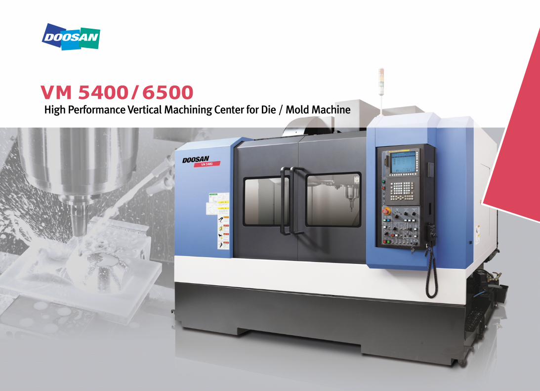
High Performance Vertical Machining Center for Die / Mold Machine
High Performance Vertical Machining Center
for Die / Mold Machine
02 High Performance Vertical Machining Center for Die / Mold Machine
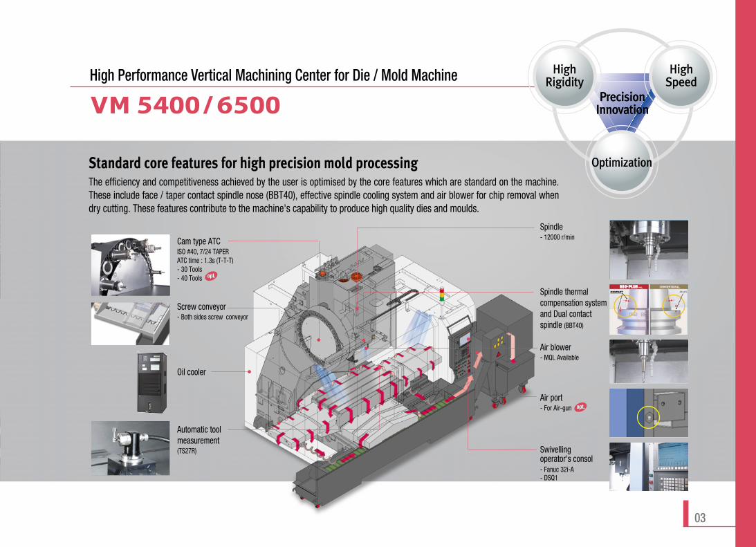
Standard core features for high precision mold processingThe efficiency and competitiveness achieved by the user is optimised by the core features which are standard on the machine.These include face / taper contact spindle nose (BBT40), effective spindle cooling system and air blower for chip removal whendry cutting. These features contribute to the machine's capability to produce high quality dies and moulds.
High Performance Vertical Machining Center for Die / Mold Machine
Spindle thermalcompensation systemand Dual contactspindle (BBT40)
Air blower- MQL Available
Spindle- 12000 r/minCam type ATC
ISO #40, 7/24 TAPERATC time : 1.3s (T-T-T)- 30 Tools- 40 Tools
Automatic toolmeasurement(TS27R)
Oil cooler
Screw conveyor - Both sides screw conveyor
Air port- For Air-gun
Optimization
HighRigidity
HighSpeed
PrecisionInnovationPrecisionInnovation
Swivelling operator's consol- Fanuc 32i-A- DSQ1
opt.
opt.
03
VM 5400/6500
DSQ package
CAM DATA
ATACard
Dataserver
100Mbps LAN interface
Mass storage program record High speed calculation Program
High speedrisk board
High speed, high precision control S/W
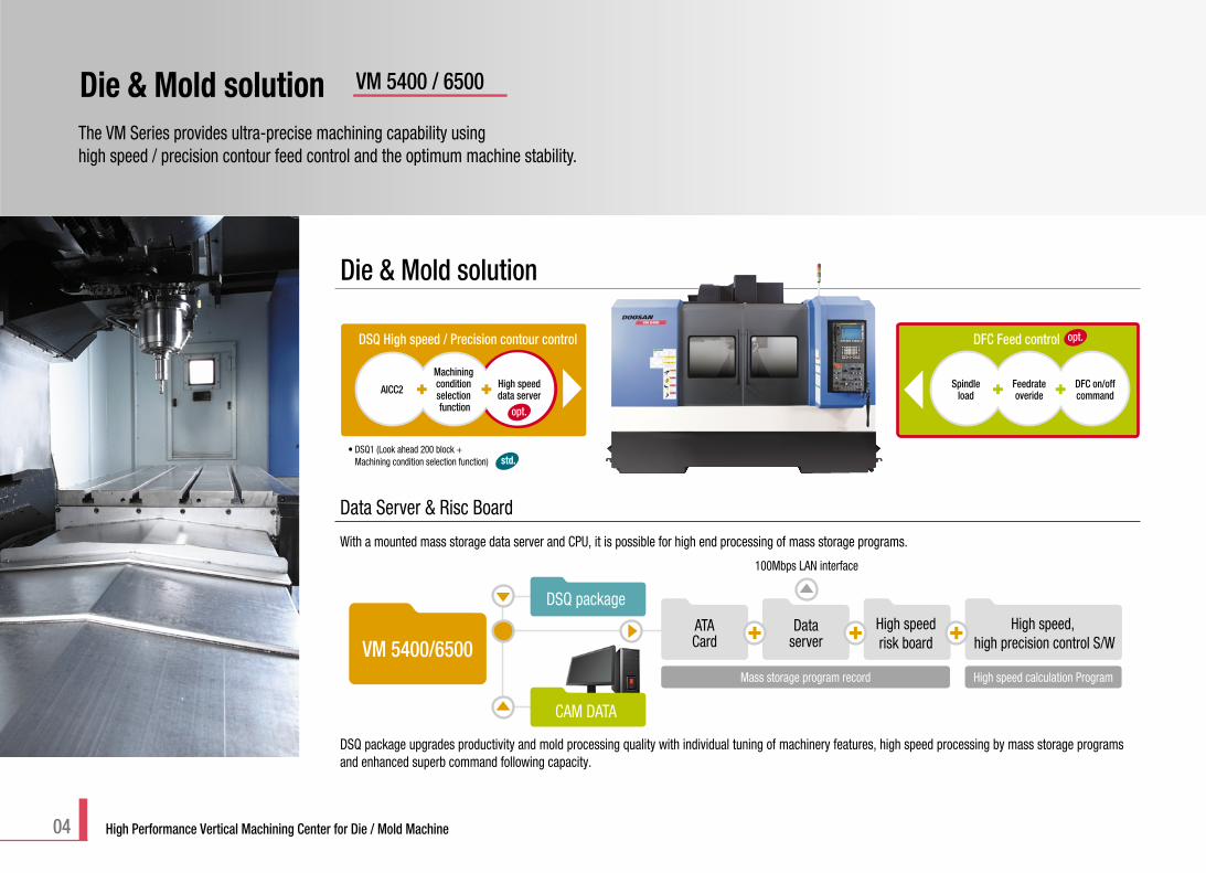
Data Server & Risc Board
With a mounted mass storage data server and CPU, it is possible for high end processing of mass storage programs.
DSQ package upgrades productivity and mold processing quality with individual tuning of machinery features, high speed processing by mass storage programsand enhanced superb command following capacity.
The VM Series provides ultra-precise machining capability using high speed / precision contour feed control and the optimum machine stability.
Die & Mold solution VM 5400 / 6500
04 High Performance Vertical Machining Center for Die / Mold Machine
Die & Mold solution
AICC2
DSQ High speed / Precision contour control
Machining condition selection function
High speeddata server
opt.
Spindleload
Feedrateoveride
DFC on/offcommand
DFC Feed control opt.
• DSQ1 (Look ahead 200 block + Machining condition selection function) std.
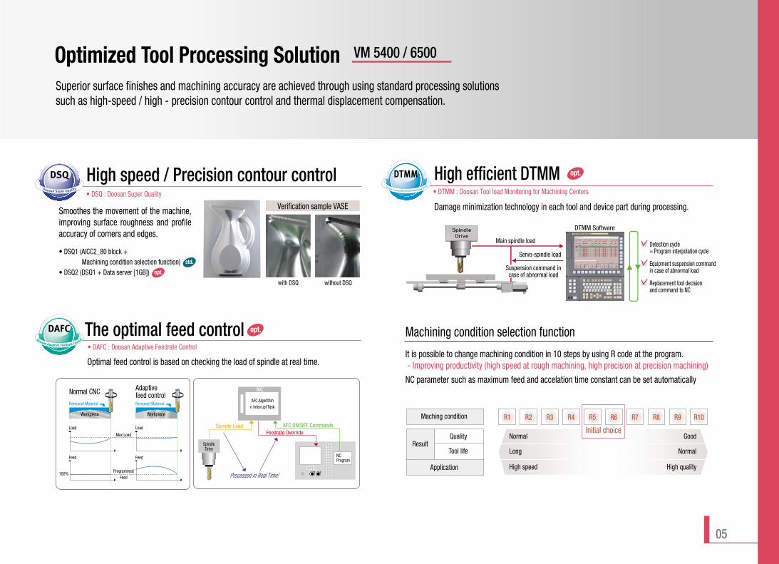
Superior surface finishes and machining accuracy are achieved through using standard processing solutionssuch as high-speed / high - precision contour control and thermal displacement compensation.
Optimized Tool Processing Solution
05
Main spindle load
DTMM Software
Detection cycle = Program interpolation cycle
Equipment suspension command in case of abnormal load
Replacement tool decision and command to NC
Servo-spindle load
Suspension command incase of abnormal load
with DSQ without DSQ
Smoothes the movement of the machine,improving surface roughness and profileaccuracy of corners and edges.
Verification sample VASE
• DSQ1 (AICC2_80 block + Machining condition selection function)
• DSQ2 (DSQ1 + Data server [1GB]) opt.
std.
Machining condition selection function
Maching condition R1 R2 R3 R4 R5 R6 R7 R8 R9 R10
Application
ResultQuality Normal
Long
High speed
Good
Normal
High quality
Tool life
Initial choice
It is possible to change machining condition in 10 steps by using R code at the program. - Improving productivity (high speed at rough machining, high precision at precision machining)
NC parameter such as maximum feed and accelation time constant can be set automatically
Removed Material
Adaptive feed controlNormal CNC
Removed Material
Workpiece
Load
Max Load
100% ProgrammedFeed
Load
Feed Feed
Workpiece
NC
AFC Algorithmn Interrupt Task
Spindle Load AFC ON/OFF CommandsFeedrate Override
Processed in Real Time!
SpindleDrive
NCProgram
VM 5400 / 6500
High efficient DTMM• DTMM : Doosan Tool load Monitoring for Machining Centers
Damage minimization technology in each tool and device part during processing.
Optimal feed control is based on checking the load of spindle at real time.
The optimal feed control• DAFC : Doosan Adaptive Feedrate Control
opt.
opt.High speed / Precision contour control• DSQ : Doosan Super Quality
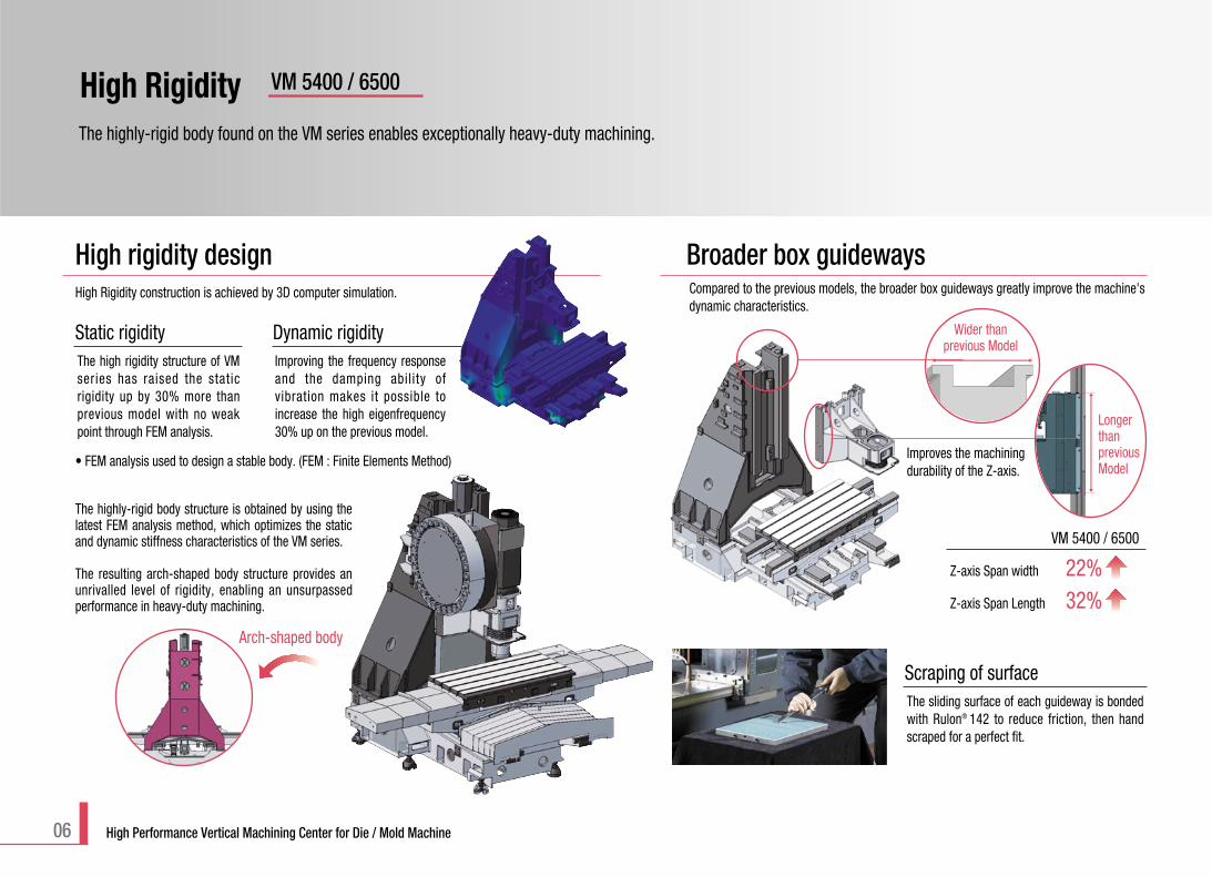
High rigidity designHigh Rigidity construction is achieved by 3D computer simulation.
Static rigidityThe high rigidity structure of VMseries has raised the staticrigidity up by 30% more thanprevious model with no weakpoint through FEM analysis.
Dynamic rigidityImproving the frequency responseand the damping abil ity ofvibration makes it possible toincrease the high eigenfrequency30% up on the previous model.
• FEM analysis used to design a stable body. (FEM : Finite Elements Method)
The highly-rigid body found on the VM series enables exceptionally heavy-duty machining.
High Rigidity VM 5400 / 6500
06 High Performance Vertical Machining Center for Die / Mold Machine
Compared to the previous models, the broader box guideways greatly improve the machine'sdynamic characteristics.
Improves the machiningdurability of the Z-axis.
Broader box guideways
VM 5400 / 6500
Wider thanprevious Model
Z-axis Span width 22%Z-axis Span Length 32%
Longer thanprevious Model
Scraping of surfaceThe sliding surface of each guideway is bondedwith Rulon® 142 to reduce friction, then handscraped for a perfect fit.
The highly-rigid body structure is obtained by using thelatest FEM analysis method, which optimizes the staticand dynamic stiffness characteristics of the VM series.
The resulting arch-shaped body structure provides anunrivalled level of rigidity, enabling an unsurpassedperformance in heavy-duty machining.
Arch-shaped body
Common utilization of BT40 Tool and2-face binding tool (BIG PLUS)
Angular Ball Bearing
Oil Cooling
Tool UnclampCylinder
Direct Coupling
CartrideType Spindle
FanucSpindle Motor
Powershutdown
Emergencystop
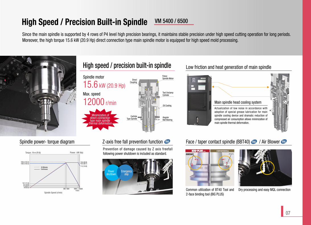
Since the main spindle is supported by 4 rows of P4 level high precision bearings, it maintains stable precision under high speed cutting operation for long periods.Moreover, the high torque 15.6 kW (20.9 Hp) direct connection type main spindle motor is equipped for high speed mold processing.
High Speed / Precision Built-in Spindle VM 5400 / 6500
Actualization of low noise in accordance withadoption of special grease lubrication for mainspindle cooling device and dramatic reduction ofcompressed air consumption allows minimization ofmain spindle thermal deformation.
Dry processing and easy MQL connection
Main spindle head cooling system
07
15.6 kW (20.9 Hp)
12000 r/min
Spindle motor
Max. speed
High speed / precision built-in spindle Low friction and heat generation of main spindle
Face / taper contact spindle (BBT40) / Air BlowerSpindle power- torque diagram Z-axis free fall prevention function Std. Std. Std.
Power : kW (Hp)Torque : N.m (ft.lb)
949111673
1200010649008.8 (6.5)
12.7 (9.4)11.8 (8.7)
15.7 (11.6)
140.0 (103.3)15.6 (20.9)15.0 (20.1)11.0 (14.8)
165.6 (122.2)
Spindle Speed (r/min)
30 MinutesContinuous
Prevention of damage caused by Z axis freefallfollowing power shutdown is included as standard.
Minimization of direct-connection type main spindle
thermal deformation
08 High Performance Vertical Machining Center for Die / Mold Machine
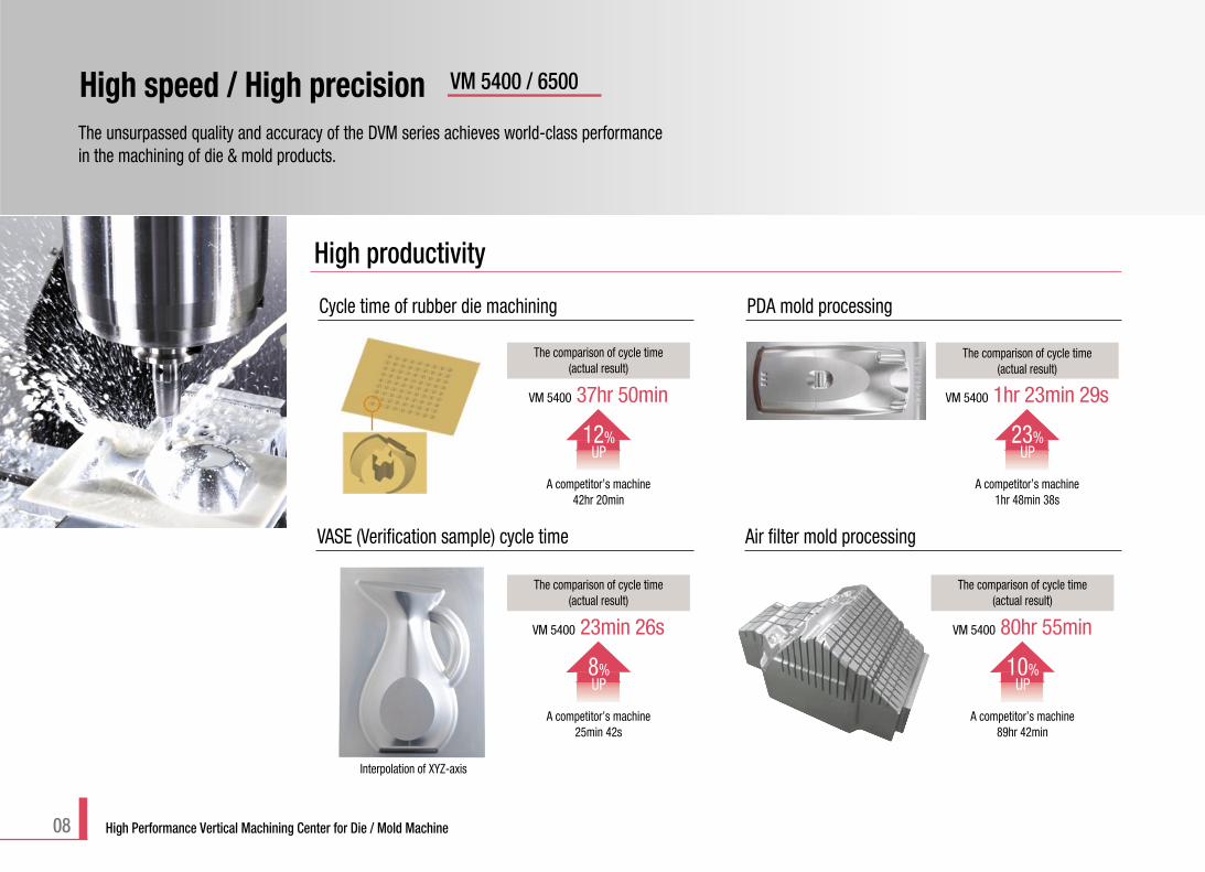
The comparison of cycle time(actual result)
A competitor’s machine25min 42s
VM 5400 23min 26s
8%UP
VASE (Verification sample) cycle time
High productivity
Cycle time of rubber die machining
The comparison of cycle time(actual result)
A competitor’s machine42hr 20min
VM 5400 37hr 50min
12%UP
Interpolation of XYZ-axis
The comparison of cycle time(actual result)
A competitor’s machine89hr 42min
VM 5400 80hr 55min
10%UP
Air filter mold processing
PDA mold processing
The comparison of cycle time(actual result)
A competitor’s machine1hr 48min 38s
VM 5400 1hr 23min 29s
23%UP
The unsurpassed quality and accuracy of the DVM series achieves world-class performancein the machining of die & mold products.
High speed / High precision VM 5400 / 6500
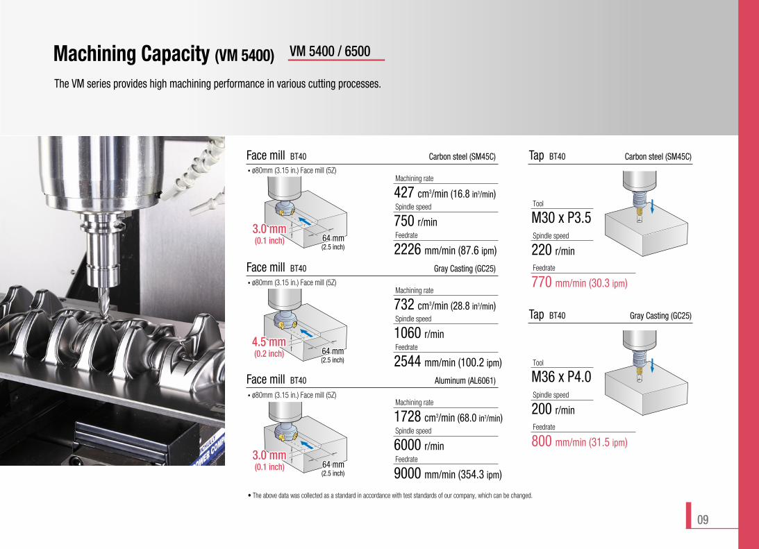
Machining Capacity (VM 5400)
The VM series provides high machining performance in various cutting processes.
VM 5400 / 6500
Face mill BT40 Carbon steel (SM45C)
3.0 mm3.0 mm(0.1 inch) 64 mm64 mm
(2.5 inch)
4.5 mm64 mm
3.0 mm64 mm
Machining rate
427 cm3/min (16.8 in3/min)Spindle speed
750 r/minFeedrate
2226 mm/min (87.6 ipm)
Face mill BT40 Gray Casting (GC25)
3.0 mm64 mm
4.5 mm4.5 mm(0.2 inch) 64 mm64 mm
(2.5 inch)
3.0 mm64 mm
Machining rate
732 cm3/min (28.8 in3/min)Spindle speed
1060 r/minFeedrate
2544 mm/min (100.2 ipm)
Face mill BT40 Aluminum (AL6061)
3.0 mm64 mm
4.5 mm64 mm
3.0 mm3.0 mm(0.1 inch) 64 mm64 mm
(2.5 inch)
Machining rate
1728 cm3/min (68.0 in3/min)Spindle speed
6000 r/minFeedrate
9000 mm/min (354.3 ipm)
Tap BT40 Gray Casting (GC25)
Tool
M36 x P4.0Spindle speed
200 r/minFeedrate
800 mm/min (31.5 ipm)
Tap BT40 Carbon steel (SM45C)
Tool
M30 x P3.5Spindle speed
220 r/minFeedrate
770 mm/min (30.3 ipm)
• ø80mm (3.15 in.) Face mill (5Z)
• ø80mm (3.15 in.) Face mill (5Z)
• ø80mm (3.15 in.) Face mill (5Z)
• The above data was collected as a standard in accordance with test standards of our company, which can be changed.
09
10 High Performance Vertical Machining Center for Die / Mold Machine
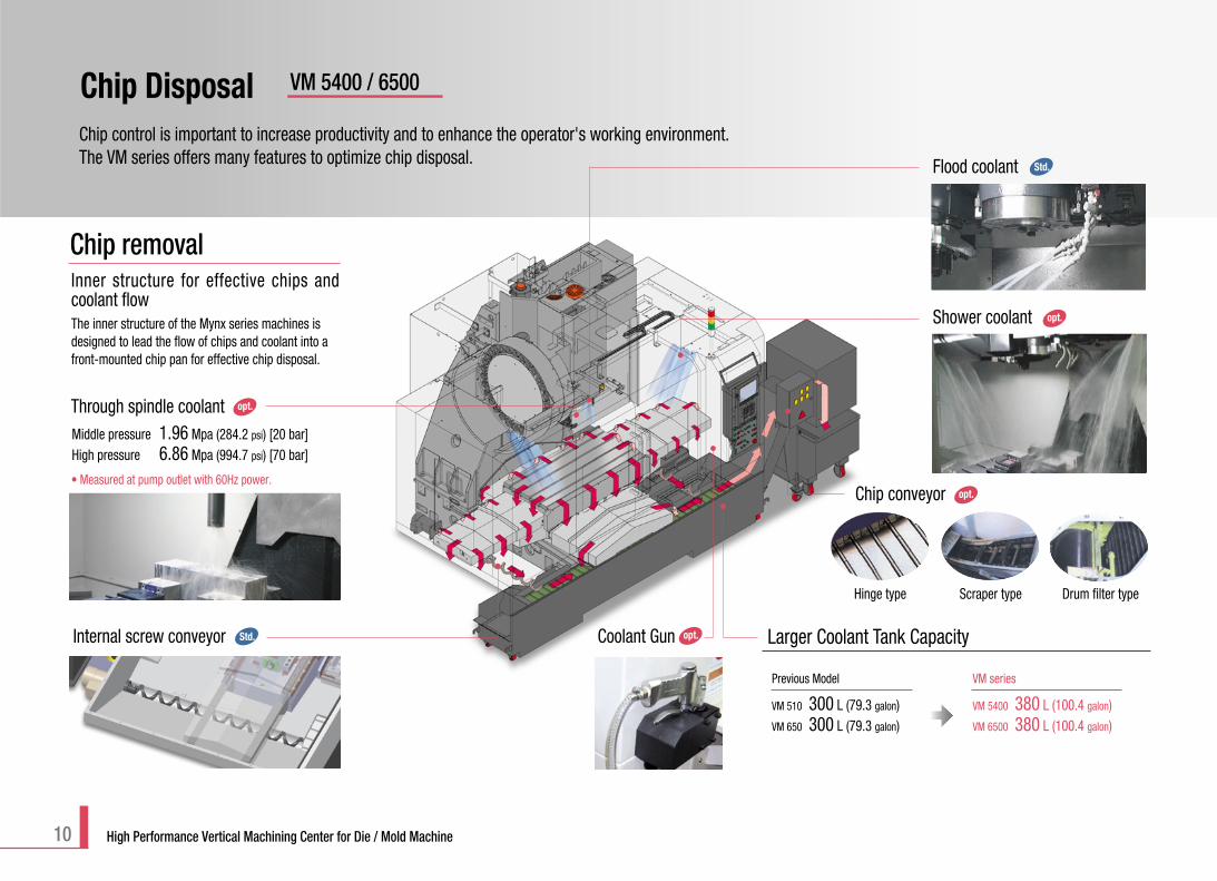
Chip DisposalChip control is important to increase productivity and to enhance the operator's working environment. The VM series offers many features to optimize chip disposal.
Internal screw conveyor Coolant Gun
Through spindle coolant
Shower coolant
Flood coolant
opt.
Chip conveyor opt.
opt.
opt.
Hinge type Scraper type Drum filter type
Middle pressure 1.96 Mpa (284.2 psi) [20 bar]High pressure 6.86 Mpa (994.7 psi) [70 bar]
VM 5400 / 6500
Previous Model VM series
VM 510 300 L (79.3 galon)VM 650 300 L (79.3 galon)
VM 5400 380 L (100.4 galon)VM 6500 380 L (100.4 galon)
Larger Coolant Tank Capacity
Std.
Std.
Chip removal
The inner structure of the Mynx series machines isdesigned to lead the flow of chips and coolant into afront-mounted chip pan for effective chip disposal.
• Measured at pump outlet with 60Hz power.
Inner structure for effective chips andcoolant flow
11
Easy Set-up VM 5400 / 6500
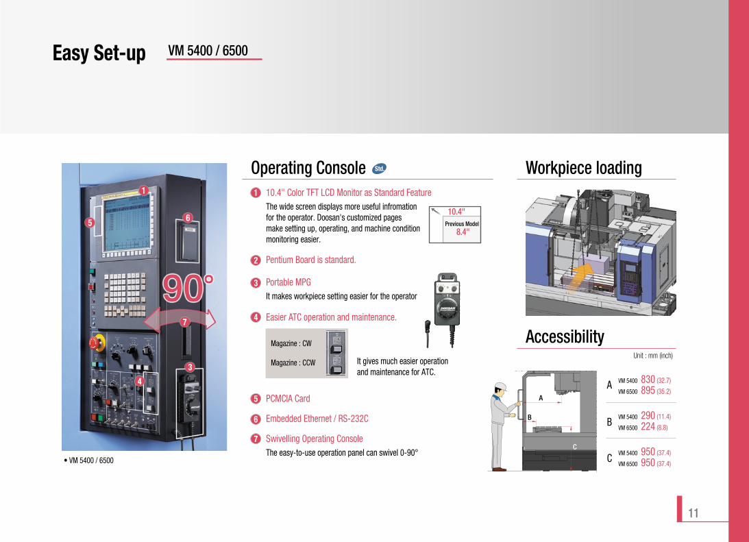
PCMCIA Card
Embedded Ethernet / RS-232C
Swivelling Operating ConsoleThe easy-to-use operation panel can swivel 0-90°
Easier ATC operation and maintenance.
Portable MPGIt makes workpiece setting easier for the operator
Pentium Board is standard.
10.4" Color TFT LCD Monitor as Standard Feature The wide screen displays more useful infromation for the operator. Doosan's customized pages make setting up, operating, and machine condition monitoring easier.
It gives much easier operation and maintenance for ATC.
• VM 5400 / 6500
Workpiece loading
Accessibility
A
B
C
Operating Console
Magazine : CW
Magazine : CCWUnit : mm (inch)
Std.
5 6
1 1
2
3
4
5
6
7
7
3
4
8.4"Previous Model
10.4"
VM 5400 830 (32.7)
VM 6500 895 (35.2)A
B
C
VM 5400 290 (11.4)
VM 6500 224 (8.8)
VM 5400 950 (37.4)
VM 6500 950 (37.4)
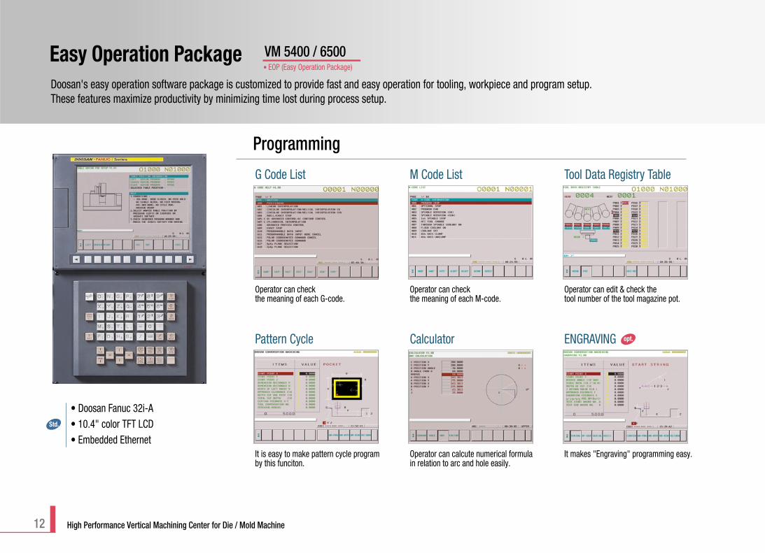
Easy Operation PackageDoosan's easy operation software package is customized to provide fast and easy operation for tooling, workpiece and program setup. These features maximize productivity by minimizing time lost during process setup.
VM 5400 / 6500
12 High Performance Vertical Machining Center for Die / Mold Machine
Programming
Operator can edit & check the tool number of the tool magazine pot.
Tool Data Registry Table
Operator can checkthe meaning of each G-code.
G Code List
Operator can checkthe meaning of each M-code.
M Code List
It is easy to make pattern cycle programby this funciton.
Pattern Cycle
It makes "Engraving" programming easy.
ENGRAVING
Operator can calcute numerical formulain relation to arc and hole easily.
Calculator opt.
• Doosan Fanuc 32i-A• 10.4" color TFT LCD• Embedded Ethernet
Std.
• EOP (Easy Operation Package)
13
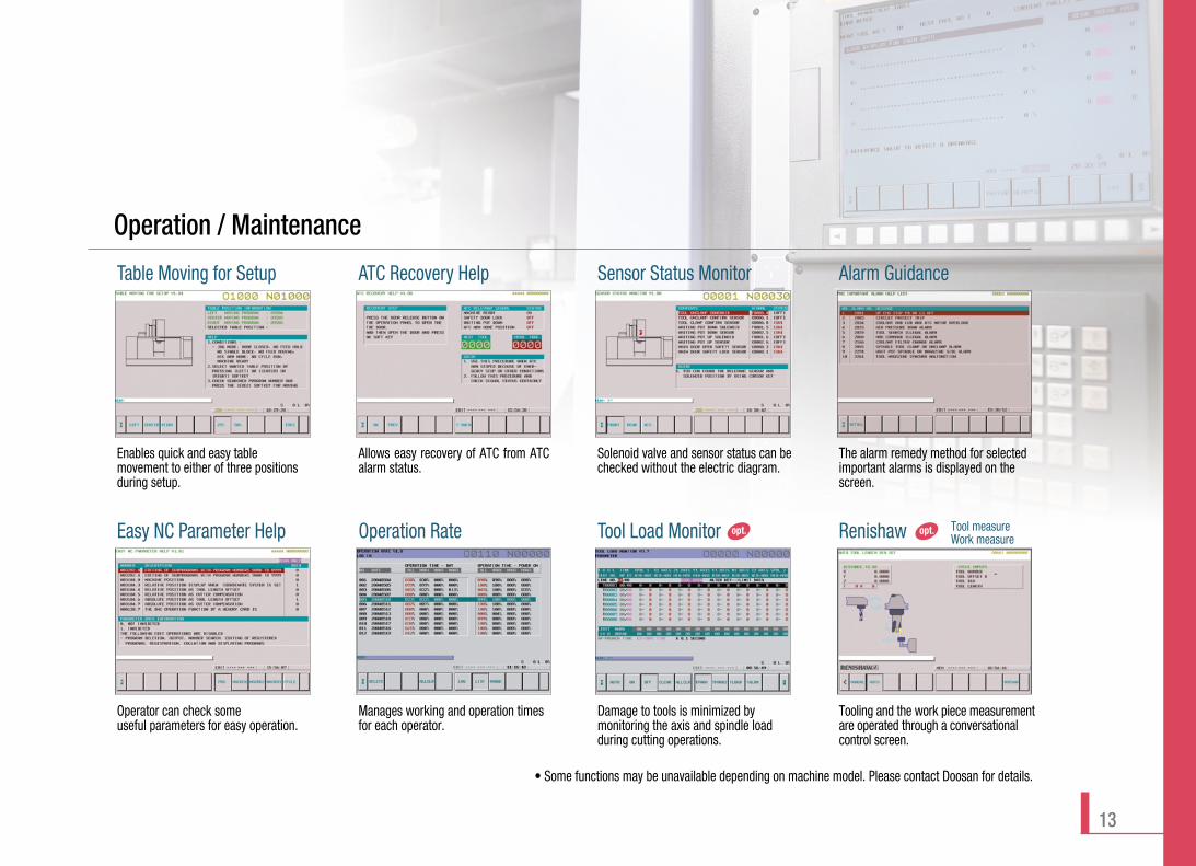
• Some functions may be unavailable depending on machine model. Please contact Doosan for details.
Operation / Maintenance
Allows easy recovery of ATC from ATCalarm status.
ATC Recovery Help
Solenoid valve and sensor status can bechecked without the electric diagram.
Sensor Status Monitor
Enables quick and easy tablemovement to either of three positionsduring setup.
Table Moving for Setup
Operator can check someuseful parameters for easy operation.
Easy NC Parameter Help
Damage to tools is minimized bymonitoring the axis and spindle loadduring cutting operations.
Tool Load Monitor
Manages working and operation timesfor each operator.
Operation Rate
The alarm remedy method for selectedimportant alarms is displayed on thescreen.
Alarm Guidance
opt. opt.
Tooling and the work piece measurementare operated through a conversationalcontrol screen.
Renishaw Tool measureWork measure
14 High Performance Vertical Machining Center for Die / Mold Machine
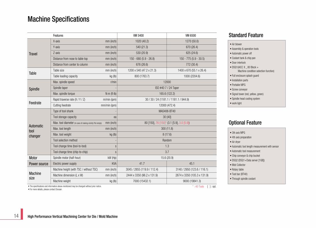
X-axis mm (inch) 1020 (40.2) 1270 (50.0)
Y-axis mm (inch) 540 (21.3) 670 (26.4)
Z-axis mm (inch) 530 (20.9) 625 (24.6)
Distance from nose to table top mm (inch) 150 - 680 (5.9 - 26.8) 150 - 775 (5.9 - 30.5)
Distance from center to column mm (inch) 676 (26.6) 772 (30.4)
Table size mm (inch) 1200 x 540 (47.2 x 21.3) 1400 x 670 (55.1 x 26.4)
Table loading capacity kg (lb) 800 (1763.7) 1000 (2204.6)
Max. spindle speed r/min 12000
Spindle taper - ISO #40 7 / 24 Taper
Max. spindle torque N.m (ft.lb) 165.6 (122.2)
Rapid traverse rate (X / Y / Z) m/min (ipm) 30 / 30 / 24 (1181.1 / 1181.1 / 944.9)
Cutting feedrate mm/min (ipm) 12000 (472.4)
Type of tool shank - MAS406-BT40
Tool storage capacity ea 30 {40}
Max. tool diameter (In case of making vicinity Pot empty) mm (inch) 80 [150], 76 [150]* (3.1 [5.9], 3.0 [5.9])
Max. tool length mm (inch) 300 (11.8)
Max. tool weight kg (lb) 8 (17.6)
Tool selection method - Random
Tool change time (tool-to-tool) s 1.3
Tool change time (chip-to-chip) s 3.7
Spindle motor (half-hour) kW (Hp) 15.6 (20.9)
Electric power supply KVA 41.7 45.1
Machine height (with TSC / without TSC) mm (inch) 3045 / 2855 (119.9 / 112.4) 3140 / 2950 (123.6 / 116.1)
Machine dimension (L x W) mm (inch) 2444 x 3350 (96.2 x 131.9) 2674 x 3350 (105.3 x 131.9)
Machine weight kg (lb) 7000 (15432.1) 9000 (19841.3)
Features VM 5400 VM 6500
Travel
Table
Spindle
Feedrate
Automatictoolchanger
Motor
Machinesize
Power source
* : 40 Tools { } : opt.
Standard Feature
Optional Feature
• Air blower
• Assembly & operation tools
• Automatic power off
• Coolant tank & chip pan
• Door interlock
• DSQ1(AICC II _ 80 Block +Machine condition selection function)
• Full enclosure splash guard
• Installation parts
• Portable MPG
• Screw conveyor
• Signal tower (red, yellow, green)
• Spindle head cooling system
• work light
• 3th axis MPG
• 4th axis preparation
• Air dryer
• Automatic tool length measurement with sensor
• Automatic tool measurement
• Chip conveyor & chip bucket
• DSQ2 (DSQ1+Data server [1GB])
• Mist Collector
• Rotary table
• Test bar (BT40)
• Through spindle coolant
Machine Specifications
• The specifications and information above-mentioned may be changed without prior notice.• For more details, please contact Doosan.
15
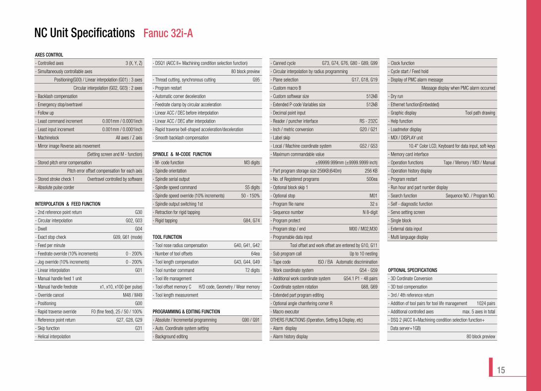
NC Unit Specifications Fanuc 32i-A
AXES CONTROL
- Controlled axes 3 (X, Y, Z)
- Simultaneously controllable axes
Positioning(G00) / Linear interpolation (G01) : 3 axes
Circular interpolation (G02, G03) : 2 axes
- Backlash compensation
- Emergency stop/overtravel
- Follow up
- Least command increment 0.001mm / 0.0001inch
- Least input increment 0.001mm / 0.0001inch
- Machinelock All axes / Z axis
- Mirror image Reverse axis movement
(Setting screen and M - function)
- Stored pitch error compensation
Pitch error offset compensation for each axis
- Stored stroke check 1 Overtravel controlled by software
- Absolute pulse corder
INTERPOLATION & FEED FUNCTION
- 2nd reference point return G30
- Circular interpolation G02, G03
- Dwell G04
- Exact stop check G09, G61 (mode)
- Feed per minute
- Feedrate override (10% increments) 0 - 200%
- Jog override (10% increments) 0 - 200%
- Linear interpolation G01
- Manual handle feed 1 unit
- Manual handle feedrate x1, x10, x100 (per pulse)
- Override cancel M48 / M49
- Positioning G00
- Rapid traverse override F0 (fine feed), 25 / 50 / 100%
- Reference point return G27, G28, G29
- Skip function G31
- Helical interpolation
- DSQ1 (AICC II+ Machining condition selection function)
80 block preview
- Thread cutting, synchronous cutting G95
- Program restart
- Automatic corner deceleration
- Feedrate clamp by circular acceleration
- Linear ACC / DEC before interpolation
- Linear ACC / DEC after interpolation
- Rapid traverse bell-shaped acceleration/deceleration
- Smooth backlash compensation
SPINDLE & M-CODE FUNCTION
- M- code function M3 digits
- Spindle orientation
- Spindle serial output
- Spindle speed command S5 digits
- Spindle speed override (10% increments) 50 - 150%
- Spindle output switching 1st
- Retraction for rigid tapping
- Rigid tapping G84, G74
TOOL FUNCTION
- Tool nose radius compensation G40, G41, G42
- Number of tool offsets 64ea
- Tool length compensation G43, G44, G49
- Tool number command T2 digits
- Tool life management
- Tool offset memory C H/D code, Geometry / Wear memory
- Tool length measurement
PROGRAMMING & EDITING FUNCTION
- Absolute / Incremental programming G90 / G91
- Auto. Coordinate system setting
- Background editing
- Canned cycle G73, G74, G76, G80 - G89, G99
- Circular interpolation by radius programming
- Plane selection G17, G18, G19
- Custom macro B
- Custom softwear size 512kB
- Extended P-code Variables size 512kB
- Decimal point input
- Reader / puncher interface RS - 232C
- Inch / metric conversion G20 / G21
- Label skip
- Local / Machine coordinate system G52 / G53
- Maximum commandable value
±99999.999mm (±9999.9999 inch)
- Part program storage size 256KB(640m) 256 KB
- No. of Registered programs 500ea
- Optional block skip 1
- Optional stop M01
- Program file name 32 s
- Sequence number N 8-digit
- Program protect
- Program stop / end M00 / M02,M30
- Programable data input
Tool offset and work offset are entered by G10, G11
- Sub program call Up to 10 nesting
- Tape code ISO / EIA Automatic discrimination
- Work coordinate system G54 - G59
- Additional work coordinate system G54.1 P1 - 48 pairs
- Coordinate system rotation G68, G69
- Extended part program editing
- Optional angle chamfering corner R
- Macro executor
OTHERS FUNCTIONS (Operation, Setting & Display, etc)
- Alarm display
- Alarm history display
- Clock function
- Cycle start / Feed hold
- Display of PMC alarm message
Message display when PMC alarm occurred
- Dry run
- Ethernet function(Embedded)
- Graphic display Tool path drawing
- Help function
- Loadmeter display
- MDI / DISPLAY unit
10.4" Color LCD, Keyboard for data input, soft-keys
- Memory card interface
- Operation functions Tape / Memory / MDI / Manual
- Operation history display
- Program restart
- Run hour and part number display
- Search function Sequence NO. / Program NO.
- Self - diagnostic function
- Servo setting screen
- Single block
- External data input
- Multi language display
OPTIONAL SPECIFICATIONS
- 3D Cordinate Conversion
- 3D tool compensation
- 3rd / 4th reference return
- Addition of tool pairs for tool life management 1024 pairs
- Additional controlled axes max. 5 axes in total
- DSQ 2 (AICC II+Machining condition selection function+
Data server+1GB)
80 block preview
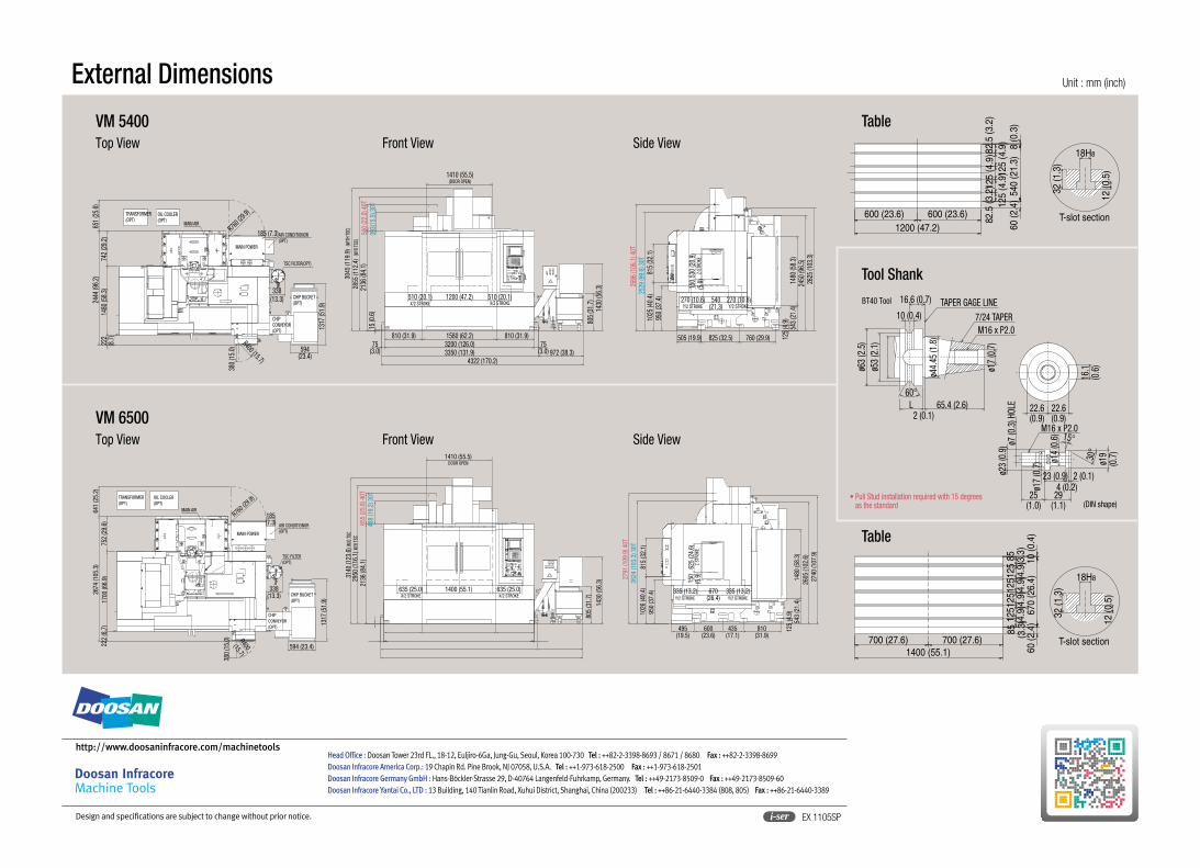
Unit : mm (inch)External Dimensions
Top View Front View Side View
VM 5400
Top View Front View Side View
VM 6500
Table
Table
Tool Shank
R400 (15.7)
R760 (29
.9)
380
(15.
0)
222
(8.7
)14
80 (5
8.3)
742
(29.
2)24
44 (9
6.2)
338(13.3)
1317
(51.
9)
594(23.4)
651
(25.
6)
185 (7.3)
CHIPCONVEYOR(OPT)
TSC FILTER(OPT)
AIR CONDITIONOR(OPT)
MAIN POWER
MAIN AIR
TRANSFORMER(OPT)
OIL COOLER(OPT)
CHIP BUCKET(OPT)
1410 (55.5)
3045
(119
.9)
(WITH
TSC)
(DOOR OPEN)
2855
(112
.4)
(W/O
TSC)
2136
(84.
1)15
(0.6
)
75(3.0)
4322 (170.2)3350 (131.9) 972 (38.3)3200 (126.0) 75
(3.0)
810 (31.9) 1580 (62.2) 810 (31.9)
805
(31.
7)14
30 (5
6.3)
560
(22.
0) 4
0T39
3(15
.5) 3
0T
510 (20.1)X/2 STROKE
1200 (47.2) 510 (20.1)X/2 STROKE
1480
(58.
3)24
50 (9
6.5)
2625
(103
.3)
125
(4.9
)
505 (19.9) 825 (32.5) 760 (29.9)
950
(37.
4)10
25 (4
0.4)
815
(32.
1)
2696
(106
.1) 4
0T25
29 (9
9.6)
30T
270 (10.6) 540(21.3)
270 (10.6)Y/2 STROKE Y/2 STROKE
150
(5.9
)530
(20.
9)Z-
STRO
KE
543
(21.
4)
TRANSFORMER(OPT)
OIL COOLER(OPT)
222
(8.7
)17
00 (6
6.9)
752
(29.
6)26
74 (1
05.3
)64
1 (2
5.2)
TSC FILTER(OPT)
AIR CONDITIONOR(OPT)MAIN POWER
MAIN AIR
CHIPCONVEYOR(OPT)
CHIP BUCKET(OPT)
R400(15.7)
380
(15.
0)
594 (23.4)
1317
(51.
9)
R760 (
29.9)
338(13.3)
185(7.3) 65
5 (2
5.8)
40T
2136
(84.
1)48
8 (1
9.2)
30T
2950
(116
.1) W
/O TS
C31
40 (1
23.6
) W/O
TSC
1410 (55.5)DOOR OPEN
635 (25.0) 1400 (55.1)X/2 STROKE
635 (25.0)X/2 STROKE
805
(31.
7)
1430
(56.
3)
2791
(109
.9) 4
0T26
24 (1
03.3
) 30T
950
(37.
4)10
26 (4
0.4)
815
(32.
1)
625
(24.
6)Z
STRO
KE
335 (13.2) 670(26.4)Y/2 STROKE
335 (13.2)Y/2 STROKE
495(19.5)
600(23.6)
435(17.1)
810(31.9)
1480
(58.
3)26
05 (1
02.6
)27
40 (1
07.9
)
543
(21.
4)12
5 (4
.9)
150
(5.9
)
18H8
32 (1
.3)
12 (0
.5)
T-slot section1200 (47.2)
600 (23.6) 600 (23.6)
82.5
(3.2
)12
5 (4
.9)
125
(4.9
)12
5 (4
.9)
82.5
(3.2
)
8 (0
.3)
540
(21.
3)60
(2.4
)
700 (27.6) 700 (27.6)1400 (55.1)
125
(4.9
)12
5(4
.9)
125
(4.9
)12
5(4
.9)
85 (3.3
)85 (3.3
)10
(0.4
)67
0 (2
6.4)
60 (2
.4)
T-slot section
18H8
32 (1
.3)
12 (0
.5)
ø7 (0
.3) H
OLE
ø23
(0.9
)
M16 x P2.015°
ø14
(0.6
)
29(1.1)
25(1.0)
ø17
(0.7
)
2 (0.1)4 (0.2)
23 (0.9)
ø19
(0.7
)
30°
22.6(0.9)
22.6(0.9)
16.1
(0.6
)ø17
(0.7
)
L2 (0.1)
65.4 (2.6)
ø44.
45 (1
.8)
TAPER GAGE LINE
60°
ø53
(2.1
)
16.6 (0.7)
10 (0.4) 7/24 TAPERM16 x P2.0
ø63
(2.5
)
• Pull Stud installation required with 15 degreesas the standard
BT40 Tool
EX 1105SPi-serDesign and specifications are subject to change without prior notice.
Head Office : Doosan Tower 23rd FL., 18-12, Euljiro-6Ga, Jung-Gu, Seoul, Korea 100-730 Tel : ++82-2-3398-8693 / 8671 / 8680 Fax : ++82-2-3398-8699Doosan Infracore America Corp.: 19 Chapin Rd. Pine Brook, NJ 07058, U.S.A. Tel : ++1-973-618-2500 Fax : ++1-973-618-2501Doosan Infracore Germany GmbH : Hans-Böckler-Strasse 29, D-40764 Langenfeld-Fuhrkamp, Germany. Tel : ++49-2173-8509-0 Fax : ++49-2173-8509-60Doosan Infracore Yantai Co., LTD : 13 Building, 140 Tianlin Road, Xuhui District, Shanghai, China (200233) Tel : ++86-21-6440-3384 (808, 805) Fax : ++86-21-6440-3389
http://www.doosaninfracore.com/machinetools
(DIN shape)
Recommended